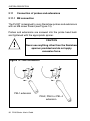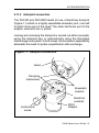
1
H-1000-5070-09-A
=>?@D
PH10 Series
User’s Guide
© 2001 Renishaw. All rights reserved.
Renishaw® is a registered trademark of Renishaw plc.
This document may not be copied or reproduced in whole or in part, or transferred to any
other media or language, by any means without the written prior permission of Renishaw.
The publication of material within this document does not imply freedom from the patent
rights of Renishaw plc.
Disclaimer
Considerable effort has been made to ensure that the contents of this document are free
from inaccuracies and omissions. However, Renishaw makes no warranties with respect
to the contents of this document and specifically disclaims any implied warranties. Renishaw
reserves the right to make changes to this document and to the product described herein
without obligation to notify any person of such changes.
Care of equipment
Renishaw probes and associated systems are precision tools used for obtaining precise
measurements and must therefore be treated with care.
Changes to equipment
Renishaw reserves the right to improve, change or modify its hardware or software without
incurring any obligations to make changes to Renishaw equipment previously sold.
Warranty
Renishaw plc warrants its equipment for a limited period (as set out in our Standard Terms
and Conditions of Sale) provided that it is installed exactly as defined in associated Renishaw
documentation. Prior consent must be obtained from Renishaw if non-Renishaw equipment
(e.g. interfaces and/or cabling) is to be used or substituted for Renishaw equipment. Failure
to comply with this will invalidate the Renishaw warranty. Claims under warranty must be
made from authorised Service Centres only, which may be advised by the supplier or
distributor.
Patents
Features of the products shown in this guide, and features of similar products, are the
subjects of the following patents and patent applications.
EP 0068899
EP 0142373
EP 0243766
EP 0293036
EP 0388993
EP 0501710
EP 0544854
EP 0740768
EP 0750171
EP 279828 B
EP 548328 B
EP 566719 B
JP 1556462
JP 2,098,080
JP 2,510,804
JP 2,545,082
JP 2,647,881
JP 501,776/1994
JP 503,652/1994
JP 507,918/1997
JP 508,476/1993
US 4462162
US 4651405
US 4813151
US 4916339
US 5,323,540
US 5,327,657
US 5,339,535
US 5,345,689
US 5,404,649
US 5,505,005
US 5,755,038
TW UM-099300
Renishaw plc
PH10
Motorised Probe Head Series
User's Guide
FCC (U.S.A.)
Information to user (FCC section 15.105)
This equipment has been tested and found to comply with the
limits for a Class A digital device, pursuant to Part 15 of the FCC
Rules. These limits are designed to provide reasonable protection
against harmful interference when the equipment is operated in a
commercial environment. This equipment generates, uses and can
radiate radio frequency energy and, if not installed and used in
accordance with the instruction manual, may cause harmful
interference to radio communications. Operation of this equipment
in a residential area is likely to cause harmful interference, in which
case you will be required to correct the interference at your own
expense.
Information to user (FCC section 15.21)
The user is cautioned that any changes or modifications not
expressly approved by Renishaw plc or its authorised
representative could void the user's authority to operate the
equipment.
Special accessories (FCC section 15.27)
The user is also cautioned that any peripheral device installed
with this equipment such as a computer, must be connected with
a high-quality shielded cable to insure compliance with FCC limits.
2 PH10 Series User's Guide
WARNINGS
GB
Pinch hazards exist between moving parts and between moving and static
parts. Do not hold the probe head during movements, or during manual
probe changes.
Beware of unexpected movement. The user should remain outside of the
full working envelope of probe head/extension/probe combinations.
In all applications involving the use of machine tools or CMMs, eye protection
is recommended.
There are no user serviceable parts inside Renishaw mains powered units.
Return defective units to an authorised Renishaw Customer Service Centre.
Replace blown fuses with new components of the same type. Refer to the
SAFETY section of the relevant product documentation.
For instructions regarding the safe cleaning of Renishaw products, refer to
the MAINTENANCE section of the relevant product documentation.
Remove power before performing any maintenance operations.
Refer to the machine supplier's operating instructions.
It is the machine supplier's responsibility to ensure that the user is made
aware of any hazards involved in operation, including those mentioned in
Renishaw product documentation, and to ensure that adequate guards
and safety interlocks are provided.
Under certain circumstances the probe signal may falsely indicate a probe
seated condition. Do not rely on probe signals to stop machine movement.
The expected method of providing an emergency stop for Renishaw products
is to remove power.
PH10 Series User's Guide 3
AVERTISSEMENTS
F
L'effet de pincement dû au mouvement des pièces mobiles entre elles ou
avec des pièces fixes présente des dangers. Ne pas tenir la tête du palpeur
lorsqu'elle se déplace ou que le palpeur est changé à la main.
Attention aux mouvements brusques. L'utilisateur doit toujours rester en
dehors de la zone de sécurité des installations multiples tête de palpeur/
rallonge/palpeur.
Le port de lunettes de protection est recommandé pour toute application
sur machine-outil et MMC.
Aucune pièce des machines Renishaw alimentées sur secteur ne peut
être réparée par l'utilisateur. Renvoyer toute machine défectueuse à un
Centre Après Vente Renishaw agréé.
Remplacer les fusibles grillés par des composants neufs du même type.
Consulter la section SAFETY (SECURITE) de votre documentation.
Les conseils de nettoyage en toute sécurité des produits Renishaw figurent
dans la section MAINTENANCE de votre documentation.
Mettre la machine hors tension avant d'entreprendre toute opération de
maintenance.
Consulter le mode d’emploi du fournisseur de la machine.
Il incombe au fournisseur de la machine d’assurer que l’utilisateur prenne
connaissance des dangers d'exploitation, y compris ceux décrits dans la
documentation du produit Renishaw, et d'assurer que des protections et
verrouillages de sûreté adéquats soient prévus.
Dans certains cas, il est possible que le signal du palpeur indique à tort
que le palpeur est au repos. Ne pas se fier aux signaux du palpeur qui ne
garantissent pas toujours l’arrêt de la machine.
La procédure habituelle d’arrêt d'urgence des produits Renishaw est la
mise hors tension.
4 PH10 Series User's Guide
ACHTUNG
D
Zwischen beweglichen und zwischen beweglichen und statischen Teilen besteht
eine Einklemmgefahr. Den Meßtasterkopf nicht anfassen, wenn er sich bewegt
oder wenn ein manueller Meßtasterwechsel durchgeführt wird.
Auf unerwartete Bewegungen achten. Der Anwender soll sich immer außerhalb
des Meßtasterkopf-Arm-Meßtaster-Bereichs aufhalten.
Bei der Bedienung von Werkzeugmaschinen oder Koordinatenmeßanlagen ist
Augenschutz empfohlen.
Die betriebenen Renishaw-Einheiten enthalten keine Teile, die vom Anwender
gewartet werden können. Im Falle von Mängeln sind diese Geräte an Ihren
Renishaw Kundendienst zu senden.
Durchgebrannte Sicherungen müssen mit gleichwertigen ersetzt werden.
Beziehen Sie sich bitte auf SAFETY (SICHERHEITSANWEISUNGEN) in der
Produktdokumentation.
Anleitungen über die sichere Reinigung von Renishaw-Produkten sind in Kapitel
MAINTENANCE (WARTUNG) in der Produktdokumentation enthalten.
Bevor Wartungsarbeiten begonnen werden, muß erst die Stromversorgung
getrennt werden.
Beziehen Sie sich auf die Wartungsanleitungen des Lieferanten.
Es obliegt dem Maschinenlieferanten, den Anwender über alle Gefahren, die
sich aus dem Betrieb der Ausrüstung, einschließlich der, die in der Renishaw
Produktdokumentation erwähnt sind, zu unterrichten und zu versichern, daß
ausreichende Sicherheitsvorrichtungen und Verriegelungen eingebaut sind.
Unter gewissen Umständen könnte das Meßtastersignal falscherweise melden,
daß der Meßtaster nicht ausgelenkt ist. Verlassen Sie sich nicht allein auf
Sondensignale, um sich über Maschinenbewegungen zu informieren.
Renishaw-Produkte sollen im Notfall durch Trennen der Stromversorgung gestoppt
werden.
PH10 Series User's Guide 5
AVVERTENZE
I
Tra le parti in moto o tra le parti in moto e quelle ferme esiste effettivamente il
pericolo di farsi del male pizzicandorsi. Evitare di afferrare la testina della sonda
quando è in moto, oppure quando si effettuano spostamenti a mano.
Fare attenzione ai movimenti inaspettati. Si raccomanda all'utente di tenersi al
di fuori dell’involucro operativo della testina della sonda, prolunghe e altre
varianti della sonda.
Si raccomanda di indossare occhiali di protezione in applicazioni che
comportano macchine utensili e macchine per misurare a coordinate.
All'interno degli apparecchi Renishaw ad alimentazione di rete elettrica, non vi
sono componenti adatti a interventi di manutenzione da parte dell'utente. In
caso di guasto, rendere l'apparecchio a uno dei Centri di Assistenza Renishaw.
I fusibili bruciati dovranno essere sostituiti con quelli dello stesso tipo.
Consultare la sezione SAFETY (SICUREZZA) della documentazione del
prodotto.
Per le istruzioni relative alla pulizia dei prodotti Renishaw, fare riferimento alla
sezione MAINTENANCE (MANUTENZIONE) della documentazione del
prodotto.
Prima di effettuare qualsiasi intervento di manutenzione, isolare dall’alimentazione
di rete.
Consultare le istruzioni d’uso del fabbricante della macchina.
Il fornitore della macchina ha la responsabilità di avvertire l'utente dei pericoli
inerenti al funzionamento della stessa, compresi quelli riportati nelle istruzioni
della Renishaw, e di mettere a disposizione i ripari di sicurezza e gli interruttori
di esclusione.
E' possibile, in certe situazioni, che la sonda emetta erroneamente un segnale
che la sonda è in posizione. Evitare di fare affidamento sugli impulsi trasmessi
dalla sonda per arrestare la macchina.
Lo stop d'emergenza per i prodotti Renishaw è l'isolamento dall'alimentazione
elettrica.
6 PH10 Series User's Guide
ADVERTENCIAS
E
Existe el peligro de atraparse los dedos entre las distintas partes móviles y entre
partes móviles e inmóviles. No sujetar la cabeza de la sonda mientras se mueve,
ni durante los cambios manuales de la sonda.
Tener cuidado con los movimientos inesperados. El usuario debe quedarse fuera
del grupo operativo completo compuesto por la cabeza de sonda/extensión/sonda
o cualquier combinación de las mismas.
Se recomienda usar protección para los ojos en todas las aplicaciones que
implican el uso de máquinas herramientas y máquinas de medición de
coordenadas.
Dentro de las unidades Renishaw que se enchufan a la red, no existen piezas
que puedan ser mantenidas por el usuario. Las unidades defectuosas deben ser
devueltas a un Centro de Servicio al Cliente Renishaw.
Sustituir los fusibles fundidos con componentes nuevos del mismo tipo. Remitirse
a la sección titulada SAFETY (SEGURIDAD) en la documentación sobre el
producto.
Para instrucciones sobre seguridad a la hora de limpiar los productos Renishaw,
remitirse a la sección titulada MAINTENANCE (MANTENIMIENTO) en la
documentación sobre el producto.
Quitar la corriente antes de emprender cualquier operación de mantenimiento.
Remitirse a las instrucciones de manejo del proveedor de la máquina.
Corresponde al proveedor de la máquina asegurar que el usuario esté consciente
de cualquier peligro que implica el manejo de la máquina, incluyendo los que se
mencionan en la documentación sobre los productos Renishaw y le corresponde
también asegurarse de proporcionar dispositivos de protección y dispositivos de
bloqueo de seguridad adecuados.
Bajo determinadas circunstancias la señal de la sonda puede indicar
erróneamente que la sonda está asentada. No fiarse de las señales de la sonda
para parar el movimiento de la máquina.
El método previsto para efectuar una parada de emergencia de los productos
Renishaw es el de quitar la corriente.
PH10 Series User's Guide 7
AVISOS
P
Figo de constrição entre peças móveis e entre peças móveis e estáticas.
Não segurar a cabeça da sonda durante o movimento ou durante mudanças
manuais de sonda.
Tomar cuidado com movimento inesperado. O utilizador deve permanecer
fora do perímetro da área de trabalho das combinações cabeça da sonda/
extensão/sonda.
Em todas as aplicações que envolvam a utilização de máquinas-ferramenta
e CMMs, recomenda-se usar protecção para os olhos.
Não há peças que possam ser consertadas pelo utilizador dentro das
unidades Renishaw alimentadas pela rede. Devolver unidades avariadas
a um Centro de Atendimento a Clientes Renishaw.
Substituir fusíveis fundidos por novos componentes do mesmo tipo.
Consultar a secção SEGURANÇA (SAFETY) da documentação do produto.
Para instruções relativas à limpeza segura de produtos Renishaw, consultar
a secção MAINTENANCE (MANUTENÇÃO) da documentação do produto.
Desligar a alimentação antes de efectuar qualquer operação de
manutenção.
Consultar as instruções de funcionamento do fornecedor da máquina.
É responsabilidade do fornecedor da máquina assegurar que o utilizador é
consciencializado de quaisquer perigos envolvidos na operação, incluindo
os mencionados na documentação do produto Renishaw e assegurar que
são fornecidos resguardos e interbloqueios de segurança adequados.
Em certas circunstâncias, o sinal da sonda pode indicar falsamente uma
condição de sonda assentada. Não confiar em sinais da sonda para parar
o movimento da máquina.
O método esperado de proporcionar uma paragem de emergência para
produtos Renishaw é desligar a alimentação.
8 PH10 Series User's Guide
ADVARSLER
DK
Der er risiko for at blive klemt mellem bevægelige dele og mellem bevægelige
og statiske dele. Hold ikke sondehovedet under bevægelse eller under
manuelle sondeskift.
Pas på uventede bevægelser. Brugeren bør holde sig uden for hele
sondehovedets/forlængerens/sondens arbejdsområde.
I alle tilfælde, hvor der anvendes værktøjs- og koordinatmålemaskiner,
anbefales det at bære øjenbeskyttelse.
Der er ingen dele inde i Renishaw-enhederne, som sluttes til lysnettet, der
kan efterses eller repareres af brugeren. Send alle defekte enheder til
Renishaws kundeservicecenter
Udskift sikringer, der er sprunget, med nye komponenter af samme type.
Se i afsnittet SAFETY (SIKKERHED) i produktdokumentatione.
Se afsnittet MAINTENANCE (VEDLIGEHOLDELSE) i produktdokumentationen for at få instruktioner til sikker rengøring af Renishawprodukter.
Afbryd strømforsyningen, før der foretages vedligeholdelse.
Se maskinleverandørens brugervejledning.
Det er maskinleverandørens ansvar at sikre, at brugeren er bekendt med
eventuelle risici i forbindelse med driften, herunder de risici, som er nævnt
i Renishaws produktdokumentation, og at sikre, at der er tilstrækkelig
afskærmning og sikkerhedsblokeringer.
Under visse omstændigheder kan sondesignalet ved en fejl angive, at
sonden står stille. Stol ikke på, at sondesignaler stopper maskinens
bevægelse.
Den forventede metode til nødstop af Renishaw-produkter er afbrydelse
strømforsyningen.
PH10 Series User's Guide 9
WAARSCHUWINGEN
NL
Er is risico op klemmen tussen de bewegende onderdelen onderling en
tussen bewegende en niet-bewegende onderdelen. De sondekop tijdens
beweging of tijdens manuele sondeveranderingen niet vasthouden.
Oppassen voor onverwachte beweging. De gebruiker dient buiten het
werkende signaalveld van de sondekop/extensie/sonde combinaties te blijven.
Het dragen van oogbescherming wordt tijdens gebruik van machinewerktuigen en CMM’s aanbevolen.
De onderdelen van Renishaw units die op het net worden aangesloten
kunnen niet door de gebruiker onderhouden of gerepareerd worden. U
kunt defecte units naar een erkend Renishaw Klantenservice Centrum
brengen of toezenden.
Doorgeslagen zekeringen met nieuwe componenten van hetzelfde type
vervangen. U wordt verwezen naar het hoofdstuk SAFETY (VEILIGHEID)
in de produktendocumentatie.
Voor het veilig reinigen van Renishaw produkten wordt verwezen naar het
hoofdstuk MAINTENANCE (ONDERHOUD) in de produktendocumentatie.
Voordat u enig onderhoud verricht dient u de stroom uit te schakelen.
De bedieningsinstructies van de machineleverancier raadplegen.
De leverancier van de machine is ervoor verantwoordelijk dat de gebruiker
op de hoogte wordt gesteld van de risico’s die verbonden zijn aan bediening,
waaronder de risico’s die vermeld worden in de produktendocumentatie
van Renishaw. De leverancier dient er tevens voor te zorgen dat de gebruiker
is voorzien van voldoende beveiligingen en veiligheidsgrendelinrichtingen.
Onder bepaalde omstandigheden kan het sondesignaal een onjuiste
sondetoestand aangeven. Vertrouw niet op de sondesignalen voor het
stoppen van de machinebeweging.
In geval van nood wordt er verwacht dat het Renishaw produkt wordt
stopgezet door de stroom uit te schakelen.
10 PH10 Series User's Guide
VARNING
SW
Risk för klämning existerar mellan rörliga delar och mellan rörliga och
stillastående delar. Håll ej i sondens huvud under rörelse eller under
manuella sondbyten.
Se upp för plötsliga rörelser. Användaren bör befinna sig utanför arbetsområdet för sondhuvudet/förlängningen/sond-kombinationerna.
Ögonskydd rekommenderas för alla tillämpningar som involverar bruket av
maskinverktyg och CMM.
Det finns inga delar som användaren kan utföra underhåll på inuti Renishaws
nätströmsdrivna enheter. Returnera defekta delar till ett auktoriserat
Renishaw kundcentra.
Byt ut smälta säkringar med nya av samma typ. Se avsnittet SAFETY
(SÄKERHET) i produktdokumentationen.
För instruktioner angående säker rengöring av Renishaws produkter, se
avsnittet MAINTENANCE (UNDERHÅLL) i produktdokumentationen.
Koppla bort strömmen innan underhåll utförs.
Se maskintillverkarens bruksanvisning.
Maskinleverantören ansvarar för att användaren informeras om de risker
som drift innebär, inklusive de som nämns i Renishaws produktdokumentation, samt att tillräckligt goda skydd och säkerhetsförreglingar
tillhandahålls.
Under vissa omständigheter kan sondens signal falskt ange att en sond är
monterad. Lita ej på sondsignaler för att stoppa maskinens rörelse.
Metoden för nödstopp för Renishaws produkter förutsätter att strömmen
kopplas bort.
PH10 Series User's Guide 11
VAROITUKSIA
FIN
Liikkuvien osien sekä liikkuvien ja staattisten osien välillä on olemassa
puristusvaara. Älä pidä kiinni anturin päästä sen liikkuessa tai vaihtaessasi
anturia käsin.
Varo äkillistä liikettä. Käyttäjän tulee pysytellä täysin anturin pään/jatkeen/
anturin yhdistelmiä suojaavan toimivan kotelon ulkopuolella.
Kaikkia työstökoneita ja koordinoituja mittauskoneita (CMM) käytettäessä
suositamme silmäsuojuksia.
Sähköverkkoon kytkettävät Renishaw-tuotteet eivät sisällä käyttäjän
huollettavissa olevia osia. Vialliset osat tulee palauttaa valtuutetulle
Renishaw-asiakaspalvelukeskukselle.
Vaihda palaneiden sulakkeiden tilalle samantyyppiset uudet sulakkeet. Lue
tuoteselosteen SAFETY (TURVALLISUUTTA) koskeva osa.
Renishaw-tuotteiden turvalliset puhdistusohjeet löytyvät tuoteselosteen
MAINTENANCE (HUOLTOA) koskevasta osasta.
Kytke pois sähköverkosta ennen huoltotoimenpiteitä.
Katso koneen toimittajalle tarkoitettuja käyttöhjeita.
Koneen toimittaja on velvollinen selittämään käyttäjälle mahdolliset käyttöön
liittyvät vaarat, mukaan lukien Renishaw’n tuoteselosteessa mainitut vaarat.
Toimittajan tulee myös varmistaa, että toimitus sisältää riittävän määrän
suojia ja lukkoja.
Tietyissä olosuhteissa anturimerkki saattaa osoittaa virheellisesti, että
kyseessä on anturiin liittyvä ongelma. Älä luota anturimerkkeihin koneen
liikkeen pysäyttämiseksi.
Renishaw-tuotteiden hätäpysäytys tehdään tavallisesti kytkemällä sähkö
pois.
12 PH10 Series User's Guide
PH10 Series User's Guide 13
SAFETY
ELECTRICAL REQUIREMENTS
The PHC10-2 is powered from the a.c. mains supply via an IEC 320 connector.
The operating voltages of the unit are as follows:
85 - 264V ac
47 - 66Hz
30W maximum
FUSE REPLACEMENT
There are two 2 Amp (T) slow-blow fuses which are used for all voltages (one is a spare).
Fuses are replaced as follows:
1. Disconnect the mains power.
2. Use a screwdriver to lever out the fuseholder to reveal the fuse.
3. Remove the fuse and replace it with a 2 Amp (T) HBC 20mm x 5mm fuse, rating
as IEC 127.
4. Replace the fuseholder.
5. Reconnect the mains power.
WARNING:
Make sure that only fuses of the specified type are used for
replacement.
This equipment must be connected to a protective earth conductor via a three core
mains (line) cable. The mains plug shall be inserted only into a socket outlet
provided with a protective earth contact. The protective earth contact shall not be
negated by the use of an extension cable without protective conductor.
WARNING:
Any interruption of the protective conductor may make the
equipment dangerous. Make sure that the grounding
requirements are strictly observed.
ENVIRONMENTAL REQUIREMENTS
The following environmental conditions comply with (or exceed) BS EN 61010-1:1993
Indoor use
IP30 (no protection against water)
Altitude
Operating
temperature
PH10
PHC10-2
Storage temperature
Relative
humidity
PH10
PHC10-2
Transient overvoltages
Pollution degree
Up to 2000m
+10°C to 40°C
0°C to +50°C
-10°C to +70°C
80% maximum for temperatures up to +31°C, linear
decrease to 50% at +40°C
80% maximum for temperatures up to +31°C, linear
decrease to 50% at +50°C
Installation category II
2
14 PH10 Series User's Guide
CONTENTS
CONTENTS
1.0
2.0
Page
INTRODUCTION
SYSTEM DESCRIPTION
2.1
Introduction
2.2
PH10 motorised probe head range
2.3
Features
2.4
PH10T
2.5
PH10M
2.6
PH10MQ
2.7
Probe head specification
2.8
PHC10-2 probe head controller
2.9
HCU1 hand control unit
2.10
PH10 probe carrying capability
2.11
Connection of probes and extensions
2.12
Probes
2.13
Probe extension bars
2.14
Styli
3.0
ACCESSORIES
3.1
Adjustment modules
3.2
Gram gauge
3.3
Machine checking gauge
3.4
Universal datum sphere
3.5
Autochange rack
4.0
SYSTEM OPERATION
4.1
Introduction
4.2
Operating modes
4.3
Dos and Don'ts
5.0
TROUBLESHOOTING
5.1
Introduction
5.2
Poor measurement performance
5.3
No probe signal
5.4
No head movement
5.5
Datum error
5.6
Obstruct error
5.7
Overload error
6.0
MAINTENANCE
6.1
Maintenance
6.2
Cleaning
USER REGISTRATION
16
17
17
18
18
19
20
21
22
23
27
28
30
32
34
38
39
39
42
43
44
45
46
46
47
48
49
49
51
51
52
53
54
55
56
56
56
57
PH10 Series User's Guide 15
INTRODUCTION
1.0
INTRODUCTION
This User's Guide will enable you to maximise the performance of
your PH10 system and ensure, safe reliable operation.
Please fill in the user registration form at the end of this guide and
return it to Renishaw plc to obtain further information on the PH10
system and accessories. This will enable Renishaw to keep you
informed of the latest product information, special offers, upgrade
news and new product developments.
You may find it useful to note below information about your system.
CMM make
CMM model
Head serial number
PHC10-2 serial number
PHC10-2 version number
NOTE
There may be variations in the installation
and use of the PH10 range of motorised
probe heads on different CMMs
This User's Guide must be read
in conjunction with
the documentation provided by
your CMM supplier
16 PH10 Series User's Guide
SYSTEM DESCRIPTION
2.0
SYSTEM DESCRIPTION
2.1
Introduction
This User's Guide describes an automated inspection system using
the Renishaw PH10 series of motorised probe heads; the PH10T,
PH10M and PH10MQ.
Information is given on the elements of the system and
accessories.
A typical installation is shown, followed by a description of manual
mode and automatic mode operation.
A list of possible operating errors is also given together with
maintenance information.
The installation of the PH10 system is described in the PH10 Series
Installation Guide (Renishaw Part Number H-1000-5071) which
is intended primarily for use by the OEM (or supplier of the CMM)
for installation and commissioning purposes.
WARNING
The components of the PH10 system are not compatible
with PH9 system components. No attempt should be
made to connect PH10 system components to a PH9
system, as this will result in damage to the product.
PH10 Series User's Guide 17
SYSTEM DESCRIPTION
2.2
PH10 motorised probe head range
Each of the heads in the PH10 range is a general-purpose, versatile
unit designed specifically for use on Direct Computer Controlled
(DCC) Coordinate Measuring Machines (CMMs).
The range consists of three heads:
•
PH10T
a shank-mounted head with two-wired probe
capability and an M8 thread
•
PH10M
a shank-mounted head with multiwired
probe capability and a Renishaw Autojoint
•
PH10MQ
a quill-mounted head with multiwired probe
capability and a Renishaw Autojoint
2.3
Features
All the heads in the range incorporate the following features:
•
•
•
•
720 indexing positions
0.5µm indexing repeatability*
7.5° indexing steps in both axes
300mm (maximum) extension bar capability*
* See Section 2.7 for specifications and test conditions.
18 PH10 Series User's Guide
SYSTEM DESCRIPTION
2.4
PH10T
Figure 1 shows the PH10T motorised probe head fitted with a
TP200 probe.
Figure 1 - PH10T
B axis
A axis
PH10 Series User's Guide 19
SYSTEM DESCRIPTION
2.5
PH10M
Figure 2 shows the PH10M motorised probe head fitted with an
AM1 adjustment module and a TP7M probe.
Figure 2 - PH10M
B axis
A axis
20 PH10 Series User's Guide
SYSTEM DESCRIPTION
2.6
PH10MQ
Figure 3 shows the PH10MQ motorised probe head fitted with an
AM2 adjustment module and TP7M probe.
Figure 3 - PH10MQ
B axis
A axis
PH10 Series User's Guide 21
SYSTEM DESCRIPTION
2.7
Probe head specification
Table 1 - Probe head specification
Repeatability of position (2F)
0.5µm (0.00002in)
Step
7.5°
A axis
0° to 105°
15 positions
B axis
-180° to +180° 48 positions
Positioning
Probe mounting
Total
720 positions
PH10T
M8 thread, 18mm (0.709in)
diameter bush face
PH10M
PH10MQ
Multiwired Autojoint
XY
Z
Dimensions from
quill face
Weight
62mm (2.44in) square
PH10T
102mm (4.09in)
PH10M
117mm (4.6in)
PH10MQ
73mm (2.87in)
PH10T
595g (20.9oz)
PH10M
620g (21.8oz)
PH10MQ
730g (25.7oz)
System operating temperature
10°C to 40°C (50°F to 104°F)
System storage temperature
-10°C to 70°C (14°F to 158°F)
22 PH10 Series User's Guide
SYSTEM DESCRIPTION
2.8
PHC10-2 probe head controller
The PH10 series of motorised probe heads can only be used in
conjunction with the PHC10-2 controller. The PHC10-2 incorporates
an integral power supply for the head, manages all head and probe
functions and communicates via a suitable interface with the CMM
computer.
It is available in two versions:
•
•
PHC10-2 RS232
PHC10-2 IEEE
Figure 4 shows the front panel.
Figure 4 - PHC10-2 front panel
PH10 Series User's Guide 23
SYSTEM DESCRIPTION
2.8
PHC10-2 probe head controller continued
2.8.1
PHC10-2 specification
Table 2 - PHC10-2 probe head controller specification
Data transmission
RS232 serial or IEEE488 parallel
Power supply
Universal, autoselecting
Voltage range
85-264V, 47-66Hz
Power connector
IEC320
Fuse
2A(T) HBC 20mm x 5mm
Dimensions
2/3 19in rack wide, 2U high
290mm x 88mm x 220mm
(11.42in x 3.46in x 2.66in)
Mounting
19in rack mounting or stand-alone
24 PH10 Series User's Guide
SYSTEM DESCRIPTION
2.8
PHC10-2 probe head controller continued
2.8.2
PHC10-2 front panel
Figure 5 shows the LEDs on the front panel of the PHC10-2. The
names, colours and functions of the LEDs are given in Table 3.
Figure 5 - LEDs
Table 3 - LEDs
LED NAME
COLOUR
DESCRIPTION
POWER ON
Green
Power on when lit
HEAD READY
Green
Head correctly locked
up and waiting for a
command
HEAD ACTIVE
Yellow
Head moving
DATUM ERROR
Red
Head not locked
OBSTRUCT ERROR
Red
Head obstructed
OVERLOAD ERROR
Red
Head overloaded
STOP
Red
PHC10-2 signal to
CMM computer
PH10 Series User's Guide 25
SYSTEM DESCRIPTION
2.8
PHC10-2 probe head controller continued
2.8.3
PHC10-2 rear panel
Figure 6 shows the rear panel of the PHC10-2.
Figure 6 - rear panel
1
2
9
10
3
11
4 5
6
7
8
12
Key
1
2
3
Switches 1-10, communications protocol selection
HCU1 connector
Either RS232 communications connector or IEEE488
communications connector
4 Version number
5 Serial number
6 Main power ON/OFF switch
7 Fuse holder
8 Mains power input
9 PICS output connector
10 Switches 11-14 and 15-18, probing system format selection
11 Probe head connector
12 Probe output connector
26 PH10 Series User's Guide
SYSTEM DESCRIPTION
2.9
HCU1 hand control unit
The HCU1 hand control unit shown in Figure 7 is an optional control
which enables the system to be used in manual mode or in a
teach cycle. An LCD dot matrix display provides information on
system status.
Figure 7 - HCU1
For further information on features and operation, see the HCU1
User's Guide (Renishaw Part Number H-1000-5016) or contact
your Renishaw supplier.
PH10 Series User's Guide 27
SYSTEM DESCRIPTION
2.10
PH10 probe carrying capability
Figure 8 shows the range of extensions, probes and styli which
can be used in conjunction with the PH10T head.
Figure 8 - Extensions, probes and styli
PEL4
PEL3
PEL2
PEL1
PH10T
M3 thread styli
28 PH10 Series User's Guide
TP200
TP2-5w
TP20
TP6
M2 thread styli
SYSTEM DESCRIPTION
PH10 probe carrying capability continued
2.10
Figure 9 shows the range of extensions, probes and styli which
can be used in conjunction with the PH10M and PH10MQ heads.
Figure 9 - Extensions, probes and styli
Shank
Quill
AM1
AM2
PH10M
PH10MQ
PAA3
PEL3
PEM3
PEL2
PAA2
PEL1
PEM2
PEM1
PEM25
PAA1
M2 thread styli
H
TP6A TP7M
TP200
TP2-5 w
TP20
TP6
OTP6M
M3 thread styli
SP600MH
M4 thread styli
When using a PH10MQ with SP600M a PEM25 extension bar is required to
achieve A = 97.5° or A = 105° in all B-axis positions
PH10 Series User's Guide 29
SYSTEM DESCRIPTION
2.11
Connection of probes and extensions
2.11.1 M8 connection
The PH10T is designed to carry Renishaw probes and extensions
with an M8 screw thread (see Figure 10).
Probes and extensions are screwed into the probe head bush
and tightened with the appropriate spnner.
CAUTION
!
Never use anything other than the Renishaw
spanner provided and do not apply
excessive force.
Figure 10 - M8 connection
PEL1 extension
PEL2, PEL3 or PEL 4
extension
30 PH10 Series User's Guide
SYSTEM DESCRIPTION
2.11.2 Autojoint connection
The PH10M and PH10MQ heads all use a Renishaw Autojoint
(Figure 11) which is a highly repeatable kinematic joint, one half
of which forms part of the head. The other half forms part of the
adaptor, extension bar or probe.
Locking and unlocking the Autojoint is carried out either manually,
using the Autojoint key, or automatically using the Renishaw
Autochange rack system. In both cases, the connection repeatability
eliminates the need for probe requalification after exchange.
Figure 11 - Autojoint connection
Head
Clamping
mechanism
Kinematic
location
Lock/unlock
screw
Electrical
contacts
PAA1
Adaptor
PH10 Series User's Guide 31
SYSTEM DESCRIPTION
2.12
Probes
2.12.1 M8 touch-trigger probes
This range of probes (see Table 4) utilises the M8 bush as a
mounting to the head. These can be fitted directly onto the PH10T
head, but when used with the PH10M or PH10MQ heads, one of
the Autojoint to M8 bush extension bars or the PAA1 adaptor must
be used (see Figure 8).
Table 4 - M8 touch-trigger probes
Probe
Diameter
Application
User's Guide
TP2-5W
13mm
Universal probe for
DCCC and manual
CMMs
H-1000-5021
TP6*
25mm
Universal probe for
DCCC and manual
CMMs
H-1000-5021
TP20
13mm
Universal probe for
DCCC and manual
CMMs with module
changing
H-1000-5008
13mm
Universal probe
with strain gauges
for DCC CMMs.
Upto 100mm stylus
carrying ability
H-1000-5150
TP200
* An Autojoint version (TP6A) is also available.
32 PH10 Series User's Guide
SYSTEM DESCRIPTION
2.12
Probes continued
2.12.2 Multiwired probes
This range of probes (see Table 5) are compatible with the PH10M
and PH10MQ heads only and utilise the Renishaw multiwired
Autojoint connection to the head.
Table 5 - Multiwire probe
Probe
Application
Diameter
Weight
User's Guide
TP7M
Universal
probe with
strain
gauges for
DCC CMMs
25mm
85g
(without
stylus)
H-1000-5010
SP600M H
Analogue
contact
scanning
probe
50mm
216g
(without
stylus)
H-1000-5175
OTP6M
Laser noncontact
optical
trigger
probe
49mm
253g max
(fitted
with
PEM1)
H-1000-5007
Probes in this range require comprehensive integration to your
CMM.
H
When using a PH10MQ with SP600M a PEM25 extension
bar is required to achieve A = 97.5° or A = 105° in all B-axis
positions
PH10 Series User's Guide 33
SYSTEM DESCRIPTION
2.13
Probe extension bars
Renishaw manufacture a comprehensive range of extension bars
and adaptors to allow increased component penetration (see
Figures 8 and 9 for allowable combinations).
There are three types in the range:
•
•
•
Autojoint to M8 bush (PAA series)
Autojoint to Autojoint (PEM series)
M8 thread to M8 bush (PEL series)
2.13.1 Autojoint to M8 bush
These extension bars connect directly to Autojoint of the PH10M
or PH10MQ head and terminate in an M8 bush (see Table 6). This
permits use of two-wire touch trigger probes.
Table 6 - Autojoint to M8 bush extensions
Extension
Length
Material
Weight
PAA1
30mm (1.18in)
Steel
57g
PAA2
140mm (5.51in)
Aluminium
85g
PAA3
300mm (11.81in)
Aluminium
144g
34 PH10 Series User's Guide
SYSTEM DESCRIPTION
2.13.1 Autojoint to M8 bush continued
The probe is fitted to the extension by hand and tightened by use
of the S1 spanner as shown in Figure 12.
Figure 12 - Fitting the PAA1 extension
The S1 spanner is designed to fail before damage can occur to
the mechanical joint between the two parts.
PH10 Series User's Guide 35
SYSTEM DESCRIPTION
2.13
Probe extension bars continued
2.13.2 Autojoint to Autojoint
These extension bars are compatible with the PH10M and
PH10MQ heads. They allow direct connection to the head via the
Autojoint and terminate in an Autojoint (see Table 7). This permits
use of a multiwired probe.
Table 7 - Autojoint to Autojoint extensions
Extension
Length
Material
Weight
PEM25
25mm (0.98in)
Aluminium
53g
PEM1
50mm (1.97in)
Aluminium
64g
PEM2
100mm (3.94in)
Aluminium
93g
PEM3
200mm (7.87)
Aluminium
145g
36 PH10 Series User's Guide
SYSTEM DESCRIPTION
2.13
Probe extension bars continued
2.13.3 M8 thread to M8 bush
These extension bars can be used directly with the PH10T head,
and also with the PH10M and PH10MQ heads using the PAA1
adaptor.
Table 8 - M8 thread to M8 bush extension bars
Extension
Length
Material
Weight
P E L1
50mm (1.97in)
Aluminium
24g
P E L2
100mm (3.94in)
Aluminium
57g
P E L3
200mm (7.87in)
Aluminium
86g
P E L4
300mm (11.81in)
Aluminium
135g
PH10 Series User's Guide 37
SYSTEM DESCRIPTION
2.14
Styli
Renishaw manufactures an extensive range of precision styli and
stylus accessories. They are available in M2, M3, M4 and M5 thread
sizes with steel, tungsten carbide, graphite fibre and ceramic stems.
Each is fitted with a precision industrial synthetic ruby ball available
in diameters from 0.3mm (0.012in) to 8.0mm (0.31in).
Special application styli including discs, cylinders, pointers, stars
and large ceramic balls up to 30mm (1.18in) are available in M2
and M3 thread sizes.
For further information on the Renishaw stylus range, please refer
to the Styli and Accessories Technical Specifications (Renishaw
Part No H-1000-3200).
Renishaw also offers a custom design service if your requirements
are not met by the standard range. Please contact your Renishaw
supplier for details.
38 PH10 Series User's Guide
ACCESSORIES
3.0
ACCESSORIES
3.1
Adjustment modules
The AM1 adjustment module shown in Figure 13 is designed for
use on the PH10T and PH10M.
Figure 13 - AM1 adjustment module
Lock/unlock screw
AM1
Roll
Pitch
Overtravel
Yaw
PH10 Series User's Guide 39
ACCESSORIES
3.1
Adjustment modules continued
The AM2 adjustment module shown in Figure 14 is designed for
use with the PH10MQ.
Figure 14 - AM2 adjustment module
Roll
Pitch
Yaw
40 PH10 Series User's Guide
ACCESSORIES
3.1
Adjustment modules continued
Both modules enable adjustment in pitch, roll and yaw and allow
accurate alignment with machine quill or workpiece.
The AM1 offers a quick release mechanism for rapid head
exchange, and features inbuilt overtravel protection.
For further information on the AM1, please refer to the AM1 User's
Guide (Renishaw Part Number H-1000-4010). For further
information on the AM2, please refer to the AM2 New Product
Information sheet (Renishaw Part Number H-1000-2051).
If your CMM has been fitted with either of the modules, the relevant
documentation should have been included. If not present, please
contact your Renishaw supplier who will arrange for a free copy to
be sent.
PH10 Series User's Guide 41
ACCESSORIES
3.2
Gram gauge
Probe trigger force is critical to ensure accuracy and reliable
operation, and can be easily measured and set using the gram
gauge as shown in Figure 15.
Figure 15 - Gram gauge
It is strongly recommended that the gram gauge is used when
adjustments are to be made to probe trigger force.
For further information on the gram gauge, please refer to the
Gram Gauge Product Information sheet (Renishaw Part Number
H-1000-2033).
Note:
To convert probe trigger force in grams to Newtons
the following equation is to be used.
Trigger force in grams = Trigger force in Newtons
100
42 PH10 Series User's Guide
ACCESSORIES
3.3
Machine checking gauge
The Renishaw machine checking gauge shown in Figure 16
enables rapid and effective interim checking of CMM performance
as recommended by many standards for CMM volumetric
performance assessment.
Figure 16 - Machine checking gauge
+45°
0°
-45°
Please contact your Renishaw representative to arrange a
demonstration, or refer to the Machine Checking Gauge User's
Guide (Renishaw Part Number H-1000-5080).
PH10 Series User's Guide 43
ACCESSORIES
3.4
Universal datum sphere
The Renishaw universal datum sphere shown in Figure 17 features
quick and easy alignment of its ball stem over a wide range of
angles, allowing clearance for probe qualification above, centrally
and below the ball.
Figure 17 - Universal datum sphere
Each hard-wearing tungsten carbide sphere is supplied with a
test certificate traceable to UK (National Physical Laboratory)
standards. For further information on the sphere please refer to
the Universal Datum Sphere Data Sheet (Renishaw Part Number
H-1000-2055).
44 PH10 Series User's Guide
ACCESSORIES
3.5
Autochange rack
Renishaw's Autochange rack shown in Figure 18 is a fullyintegrable probe exchange system available for use with the
PH10M and PH10MQ probe heads. Mounted within the CMM
working envelope, the Autochange system facilitates fast,
automatic probe exchange without the need for requalification.
Figure 18 - Autochange rack
Fast 'probing to probing' cycles are achieved by the head docking
one probe and selecting another. The highly repeatable Autojoint
removes the need to requalify after each exchange.
PH10 Series User's Guide 45
SYSTEM OPERATION
4.0
SYSTEM OPERATION
4.1
Introduction
Figure 19 shows the basic installation configuration for the PH10
system.
Figure 19 - System configuration
Machine cable
PHC10-2
head controller
Head cable
connects head to
machine cable
Communications
connection to CMM
computer
PICS Product
Interconnection cable
Probe
interface
(PI200)
Trigger output to CMM
46 PH10 Series User's Guide
HCU1
hand control
unit
(optional)
SYSTEM OPERATION
4.2
Operating modes
The PH10 system can operate in one of two modes:
•
•
Manual mode
Automatic mode
4.2.1
Manual mode
In manual mode the optional HCU1 hand control unit is used to
control head and probe functions.
If the HCU1 is connected to the PHC10-2 controller when power
is applied to the system, the system will enter manual mode.
For further information refer to the HCU1 User's Guide (Renishaw
Part Number H-1000-5016).
4.2.2
Automatic mode
In automatic mode the system is under the control of the CMM
computer. The HCU1 cannot be used to control head or probe
functions in automatic mode.
With no HCU1 fitted when power is applied to the system, the
system will enter automatic mode. The system must be switched
to manual mode under CMM control (and an HCU1 connected)
for operation under manual mode.
Please refer to the documentation provided by your CMM supplier
for further details on controlling the PH10 series of heads using
the CMM computer.
PH10 Series User's Guide 47
SYSTEM OPERATION
4.3
Dos and don'ts
DO ensure that the head is mounted as rigidly as possible in the
CMM quill.
DO take care to avoid collisions between the head and workpiece
or CMM bed.
DO ensure that the head is moved clear of any obstruction before
requesting a position change.
DO NOT apply force to any moving parts of the head.
DO NOT move the head axes by hand when locked or unlocked.
48 PH10 Series User's Guide
TROUBLESHOOTING
5.0
TROUBLESHOOTING
5.1
Introduction
Table 9 will help you to identify problems you may be experiencing
with your system.
Table 9 - Troubleshooting
Observation
Section
Poor measurement performance
5.2
No probe signal
5.3
No head movement
5.4
Datum error
5.5
Obstruct error
5.6
Overload error
5.7
If you experience problems which you are not able to identify or
solve satisfactorily, please contact your Renishaw representative
for further advice.
The optional HCU1 is also able to diagnose certain error conditions.
Please refer to the HCU1 User's Guide (Renishaw Part Number
H-1000-5016) for further information.
PH10 Series User's Guide 49
TROUBLESHOOTING
5.1
Introduction continued
NOTE
Before seeking technical assistance
please make a note of the following information:
•
•
•
•
•
•
•
Your CMM make and model
The probe head model number
The probe head serial number
The PHC10-2 serial number
The PHC10-2 version number
The LED sequence on the PHC10-2
The stylus configuration fitted
You may already have recorded
some of this information in Section 1.0
50 PH10 Series User's Guide
TROUBLESHOOTING
5.2
Poor measurement performance
Table 10 - Poor measurement performance
Possible cause
Checks/remedies
Loose head mounting
Ensure all mounting screws are
tight and mounting to the CMM
is secure
Probe incorrectly installed
Remove probe and refit
Force applied to head
during lock up
Unlock and relock
Incorrect lock up position
or position not qualified
Reposition head correctly. Check
qualification information.
5.3
No probe signal
Table 11 - No probe signal
Possible cause
Checks/remedies
Probe incorrectly installed Remove probe and refit
Cable/connection fault
Check connections and integrity
of cabling from head to controller
Probe failure
Contact your CMM supplier or
Renishaw representative for
fur ther assistance
Probe output disabled by
CMM
Check probe output
PH10 Series User's Guide 51
TROUBLESHOOTING
5.4
No head movement
Table 12 - No head movement
Possible cause
Checks/remedies
Power loss
Check controller POWER ON LED is lit.
Check mains cable connections and
integrity, observing electrical safety
precautions.
Check controller fuse, observing
electrical safety precautions (see page
14).
Check CMM emergency stop condition power may have been removed from the
system by the CMM.
Cable/connection
fault
Check connections and integrity of
cabling from head to controller.
52 PH10 Series User's Guide
TROUBLESHOOTING
5.5
Datum error
The DATUM ERROR LED is lit on the controller. The head has
rotated to the required position but locked in a non-repeatable
condition (a maximum of four attempts to lock will be made before
the error is reported).
Table 13 - Datum error
Possible cause
Checks/remedies
Cable/connection fault
Check connections and integrity
of cabling from head to controller
Head/stylus
configuration obstructed
Remove obstruction and update
head using the HCU1 or under
CMM control
Extension bar too long
Use shor ter bar
Internal head fault
Contact your Renishaw
representative, CMM
manufacturer or distributor
PH10 Series User's Guide 53
TROUBLESHOOTING
5.6
Obstruct error
The OBSTRUCT ERROR and STOP LEDs are lit on the controller.
The head has been obstructed while moving but is unable to reach
the requested position or to lock into it.
Table 14 - Obstruct error
Possible cause
Checks/remedies
Head/stylus
configuration obstructed
Check head for damage. Remove
obstruction and repeat head
move
Probe/extension
combination too long
Use shor ter/lighter combination
Internal head fault
Contact your Renishaw
representative, CMM
manufacturer or distributor
54 PH10 Series User's Guide
TROUBLESHOOTING
5.7
Overload error
The OVERLOAD ERROR and STOP LEDs are lit on the controller.
The head has been overloaded while locked.
Table 15 - Overload error
Possible cause
Checks/remedies
Head lock up holding force
exceeded during CMM
acceleration
Reduce mass of
probe/extension combination.
Reduce acceleration
Collision with workpiece or
CMM
Check head for damage.
Remove obstruction and
repeat move
PH10 Series User's Guide 55
MAINTENANCE
6.0
MAINTENANCE
6.1
Maintenance
There are no user serviceable parts inside any of the PH10 system
units. The only maintenance required is fuse replacement. See
page 14 for instructions on fuse replacement.
Units requiring attention must be returned to an authorised
Renishaw Customer Service Centre.
6.2
Cleaning
The probe head, controller and hand control unit may all be wiped
using a soft cloth.
56 PH10 Series User's Guide
USER REGISTRATION
To obtain further information on your PH10 system, and to enable
Renishaw to keep you informed with the latest product news,
please complete the user registration form overleaf and send it to:
Customer Support Department
Renishaw plc
Wotton-under-Edge
Gloucestershire
GL12 8JR
United Kingdom
NOTE
This information will be treated as strictly confidential
and will be used by Renishaw
for internal purposes only as described above
PH10 Series User's Guide 57
This page intentionally left blank
58 PH10 Series User's Guide
Please register me as a PH10 system user
Name
Position
Company name
Address
Telephone/fax
e-mail
CMM make and model
Please send me:
o
o
o
o
o
o
PH10 Series Installation Guide
Basic Command Set for Indexing Heads
Programmer's Guide
HCU1 User's Guide
Styli and Accessories Technical Specifications
Probing Systems for CMMs, Technical
Specifications
Please arrange for my nearest Renishaw
representative to contact me
PH10 Series User's Guide 59
Australia – Renishaw Oceania Pty Ltd
Tel
+61 3 9553 8267
Fax
+61 3 9592 6738
email [email protected]
Japan – Renishaw K.K.
Tel
+81 3 5332 6021
Fax
+81 3 5332 6025
email [email protected]
Brazil – Renishaw Latino Americana Ltda
Tel
+55 11 4195 2866
Fax
+55 11 4195 1641
email [email protected]
The Netherlands – Renishaw International BV
Tel
+31 76 543 11 00
Fax
+31 76 543 11 09
email [email protected]
The People’s Republic of China –
Renishaw Representative Office
Tel
+86 10 6410 7993
Fax
+86 10 6410 7992
email [email protected]
Singapore – Renishaw Representative Office
Tel
+65 897 5466
Fax
+65 897 5467
email [email protected]
France – Renishaw S.A.
Tel
+33 1 64 61 84 84
Fax
+33 1 64 61 65 26
email [email protected]
Germany – Renishaw GmbH
Tel
+49 7127 9810
Fax
+49 7127 88237
email [email protected]
Hong Kong – Renishaw (Hong Kong) Ltd.
Tel
+852 2753 0638
Fax
+852 2756 8786
email [email protected]
India – Renishaw Metrology Systems
Private Ltd
Tel
+91 80 5320 144
Fax
+91 80 5320 140
email [email protected]
Indonesia – Renishaw Representative
Office
Tel
+62 21 428 70153
Fax
+62 21 424 3934
email [email protected]
Italy – Renishaw S.p.A.
Tel
+39 011 966 10 52
Fax
+39 011 966 40 83
email [email protected]
South Korea – Renishaw Liaison Office
Tel
+82 2 565 6878
Fax
+82 2 565 6879
email [email protected]
Spain – Renishaw Iberica S.A.
Tel
+34 93 478 21 31
Fax
+34 93 478 16 08
email [email protected]
Switzerland – Renishaw A.G.
Tel
+41 55 415 50 60
Fax
+41 55 415 50 69
email [email protected]
Taiwan – Renishaw Representative Office
Tel
+886 4 251 3665
Fax
+886 4 251 3621
email [email protected]
UK (Head Office) – Renishaw plc
Tel
+44 1453 524524
Fax
+44 1453 524901
email [email protected]
USA – Renishaw Inc
Tel
+1 847 286 9953
Fax
+1 847 286 9974
email [email protected]
For all
Tel
Fax
email
other countries
+44 1453 524524
+44 1453 524901
[email protected]
=>?@D
www.renishaw.com
© 2000 Renishaw
Issued 0701
Part no. H-1000-5070-09-A