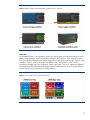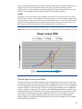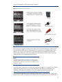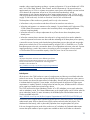
1
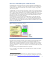
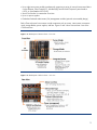
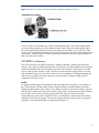
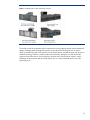
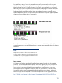
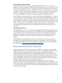
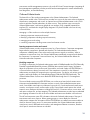
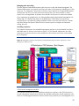
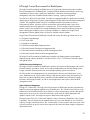
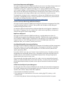
HP BladeSystem c7000 Enclosure
technology brief, 3rd edition
Abstract.............................................................................................................................................. 3 Overview of HP BladeSystem c7000 Enclosure ....................................................................................... 4 HP Thermal Logic technologies .............................................................................................................. 6 Active Cool fans .............................................................................................................................. 6 HP PARSEC architecture.................................................................................................................... 7 Parallel........................................................................................................................................ 7 Redundant ................................................................................................................................... 9 Scalable.................................................................................................................................... 10 Thermal Logic for the server blade.................................................................................................... 10 Power supplies and enclosure power subsystem................................................................................. 11 Pooled power ............................................................................................................................ 13 Dynamic Power Saver mode ........................................................................................................ 14 Power Regulator ......................................................................................................................... 15 Power Capping for each server blade........................................................................................... 16 HP BladeSystem Power Sizer ....................................................................................................... 16 Interconnect options and infrastructure.................................................................................................. 16 Interconnect modules ...................................................................................................................... 18 Server blades ................................................................................................................................ 19 Storage and other option blades...................................................................................................... 19 Mezzanine cards ........................................................................................................................... 20 Virtual Connect .............................................................................................................................. 21 Fabric connectivity and port mapping............................................................................................... 21 c7000 bay to bay crosslinks ........................................................................................................... 22 Device bay crosslinks.................................................................................................................. 23 Interconnect bay crosslinks .......................................................................................................... 23 Managing the c7000 enclosure .......................................................................................................... 23 Onboard Administrator................................................................................................................... 24 Detecting component insertion and removal................................................................................... 24 Identifying components ............................................................................................................... 24 Managing power and cooling ..................................................................................................... 25 Controlling components............................................................................................................... 25 Redundant enclosure management ............................................................................................... 26 User interfaces for Onboard Administrator .................................................................................... 26 Role-based user accounts............................................................................................................. 27 Integrated Lights-Out 2 for c-Class server blades ................................................................................ 27 Insight Display ............................................................................................................................... 27 HP Insight Control Environment for BladeSystem ................................................................................ 29 Unified Infrastructure Management ............................................................................................... 29 Lights-Out Remote Management ................................................................................................... 29 Precise Power Measurement and Regulation .................................................................................. 30 Proactive Performance Monitoring and Bottleneck Analysis.............................................................. 30 Rapid Server Deployment ............................................................................................................ 30 Consolidated Vulnerability Assessment and Patching ...................................................................... 30 Unified Virtual and Physical Systems Management ......................................................................... 30 Conclusion........................................................................................................................................ 31 Appendix: Fan and server population guidelines ................................................................................... 32 For more information.......................................................................................................................... 35 Call to action .................................................................................................................................... 35 2
Abstract
As server, storage, and network technologies have changed, traditional rack-mounted infrastructure
solutions have generated increased complexity of both infrastructure management and physical data
center deployment. The HP BladeSystem c7000 Enclosure is an evolution of the entire rack-mounted
infrastructure. It consolidates and repackages all the supporting infrastructure elements―compute,
storage, network, and power―into a single “infrastructure-in-a-box” that accelerates the integration
and optimization of the data center. This technology brief provides an overview of the HP
BladeSystem c7000 Enclosure, including Thermal Logic power and cooling technologies and
interconnect options.
This technology brief assumes the reader is familiar with HP ProLiant server technology and has some
general knowledge of BladeSystem architecture. More information about the infrastructure
components and BladeSystem technologies is available at
http://h18004.www1.hp.com/products/servers/technology/whitepapers/proliant-servers.html#bl.
3
Overview of HP BladeSystem c7000 Enclosure
The HP BladeSystem c7000 Enclosure was the first enclosure implemented using the BladeSystem
c-Class architecture. 1 It is optimized for enterprise data center applications. It fits into standard size
HP and third-party racks and accommodates the c-Class form-factor server blades, storage blades,
and interconnect modules.
The BladeSystem c7000 enclosure provides all the power, cooling, and I/O infrastructure needed to
support modular server, interconnect, and storage components today and throughout the next several
years. HP provides seamless manageability in c-Class through the Integrated Lights-Out 2 (iLO 2)
server management processor in every server blade and the Onboard Administrator that manages the
entire enclosure. Insight Control management software provides integrated management of server
blades and rack servers across the entire data center.
The HP BladeSystem c7000 Enclosure has a fully redundant design with redundant signal paths
between servers and interconnect modules (Figure 1). The NonStop signal midplane and separate
power backplane in the c7000 enclosure have no active components. Separating the high power
delivery in the backplane from the high speed interconnect signals in the midplane results in minimal
thermal stress to the signal midplane.
Figure 1. HP BladeSystem c7000 Enclosure – side view
The c7000 enclosure is10U high and includes a shared, 5-terabit-per-second, high-speed NonStop
midplane for wire-once connectivity of server blades to network and shared storage. Power is
delivered through a pooled-power backplane that ensures the full capacity of the power supplies is
available to all server blades and interconnects. The enclosure is available with a choice of singlephase AC, three-phase AC, or -48V DC power subsystem to meet the needs of the data center power
infrastructure.
The c7000 enclosure can be populated with the following components:
• Up to 8 full-height (FH) server blades or up to16 half-height (HH) server, storage, or other option
blades per enclosure
HP also offers the HP BladeSystem c3000 Enclosure, which is optimized for remote sites or small businesses.
More information about the c3000 enclosure is in the technology brief titled “HP BladeSystem c3000 Enclosure
technologies,” available at http://h20000.www2.hp.com/bc/docs/support/SupportManual/c01204885/c01204885.pdf
1
4
• Up to eight interconnect modules simultaneously supporting a variety of network interconnect fabrics
such as Ethernet, Fibre Channel (FC), InfiniBand (IB), Internet Small Computer System Interface
(iSCSI), or Serial-attached SCSI (SAS)
• Active Cool fan kits for a maximum of ten fans
• Up to six power supplies
• Redundant Onboard Administrator (OA) management modules (optional active-standby design)
Both c-Class enclosures have common critical components such as servers, interconnects, mezzanine
cards, storage blades, power supplies, and fans. Figures 2 and 3 show front and rear views of the
c7000 enclosure.
Figure 2. HP BladeSystem c7000 Enclosure – front view
Figure 3. HP BladeSystem c7000 Enclosure – rear view
5
HP Thermal Logic technologies
The HP BladeSystem c7000 Enclosure incorporates a variety of HP Thermal Logic technologies,
including mechanical design features, built-in intelligence, and control capabilities. Thermal Logic
technologies provide significant power and cooling savings—as much as 40 percent compared to
traditional rack and tower based servers. Thermal Logic technologies also provide an instant view of
power use and temperature at the server, enclosure, or rack level. They automatically adjust power
and thermal controls to minimize power and cooling use while maintaining adequate cooling for all
devices and ensuring high availability.
HP Thermal Logic technologies include the following elements and capabilities:
• Active Cool fans
• Parallel Redundant Scalable Enclosure Cooling (PARSEC) design
• Instant power and thermal monitoring
• Pooled power for a variety of power redundancy modes
• Dynamic Power Saver mode
• Power Regulator
• Power Capping
Active Cool fans
Quite often, dense, full-featured, small form-factor servers use very small fans designed to provide
localized cooling in the specific areas needed by the server blade. Because such fans generate fairly
low airflow (in cubic feet per minute, or CFM) at medium back pressure, a single server often requires
multiple fans to ensure adequate cooling. If each server blade contains several fans, installing many
server blades together in an enclosure can result in a significant cost and space overhead.
A second solution for cooling is to use larger, blower-style fans that can provide cooling across an
entire enclosure. Such fans are good at generating high airflow, but they typically require higher
power input, require more space, make more noise, and must be designed for the maximum load in
an enclosure. As a result, designers may have to sacrifice server features to allow the large, highpower fans to fit in the enclosure. Even then, ensuring adequate airflow to all the servers without
leakage, over provisioning, or bypass is a challenge.
To overcome these issues in the c7000 enclosure, HP engineers designed a new type of fan that
delivers high airflow and high pressure in a small form factor that can scale to meet future cooling
needs. HP has 20 patents pending for its Active Cool fan technology and implementation of the
technology.
HP Active Cool fans can cool 16 server blades using as little as 150 watts of power. Active Cool fans
use ducted fan technology with a high-performance motor and impeller (Figure 4) to deliver high CFM
at high pressure. The fan includes a bell mouth inlet with a specially designed impeller and a stator
section that also provides cooling fins for the motor and acoustic treatments at the rear of the fan. This
design provides cooling capacity to support blade products beyond current roadmaps. The fan’s
unique shape allows for high-volume, high-pressure airflow at even the slowest fan speeds, with low
noise levels and minimal power consumption.
6
Figure 4. Ducted fan cross-section and ducted fan blade compared to traditional server fan
Active Cool fans are controlled by the c-Class Onboard Administrator. The Onboard Administrator
can ramp cooling capacity up or down based on system needs. Along with optimizing the airflow,
the control algorithm optimizes the acoustic levels and power consumption. As a result, the c7000
enclosure can accommodate full-featured servers that are 60 percent more dense than traditional rackmount servers, while the Active Cool fans consume only 50 percent of the power typically required
and use 30 percent less airflow.
HP PARSEC architecture
The c7000 enclosure uses PARSEC architecture—parallel, redundant, scalable, enclosure-based
cooling. In this context, parallel means that fresh, cool air flows over all the blades (in the front of the
enclosure) and all the interconnect modules (in the back of the enclosure). The enclosure is divided
into four cooling zones with fans in each. The Active Cool fans provide cooling for their own zone
and redundant cooling for the rest of the enclosure. To ensure scalability, HP designed both the fans
and the power supplies with enough capacity to meet the needs of compute, storage, and I/O
components well into the future.
Parallel
To optimize thermal design, HP developed a relatively airtight center air plenum, or air chamber. In
the c7000 enclosure, all device bays include a shutoff door that is normally closed to prevent air
leakage through that device bay. When a server blade is inserted, it seals into the center air plenum
docking collar, and the server shut-off door opens to allow airflow across that server blade. Similarly,
the fan seals into the center air plenum docking collar. Each fan bay includes louvers that
automatically open when a fan is installed. If a fan is not installed or is not functional, the pressure
distribution around the fan changes. This pressure change causes the louvers to close, ensuring that
cooling air is not diverted through the non-operating fan (Figure 5).
7
Figure 5. HP BladeSystem c7000 self-sealing enclosure
The enclosure and the components within it optimize the cooling capacity through unique mechanical
designs. Managed airflow through the enclosure ensures that every device gets cool air, that no
device is situated in the path of hot exhaust air from another device, and that air goes only where it is
needed for cooling. Fresh air is pulled into the interconnect bays through a slot in the front of the
enclosure. Ducts allow the air to move from the front to the rear of the enclosure, where it is then
pulled into the interconnects and the central plenum. The air is then exhausted out the rear of the
system (Figure 6).
8
Figure 6. Airflow through the HP BladeSystem c7000 Enclosure – side view
Redundant
As illustrated in Figure 7, fans located in each of four cooling zones provide direct cooling for server
blades in their respective zone and redundant cooling for adjacent zones. Each zone can contain
four server blades. Full-height server blades couple the two vertical zones into a single zone, as in the
example in Figure 7 where a full-height server blade in bay 1 has resulted in zones 1 and 3
operating as a single zone. Fan 3 and fan 8, shown in the Figure 7 rear view, support two adjacent
horizontal zones and will operate at the higher speed of either of the two zones. If any fan fails, the
result is only a 10 to 25 percent loss in cooling capacity.
Figure 7. Four cooling zones in the c7000 enclosure
9
Zone cooling minimizes the power consumption of the fan subsystem by increasing fan efficiency in a
single zone if one of the server blades requires more cooling. This saves operating costs and
minimizes fan noise. HP recommends using at least eight fans. Using ten fans optimizes power and
cooling. See the appendix for more detailed fan and server population guidelines.
Scalable
Operating c-Class server blades requires installing a minimum of four fans at the rear of the c7000
enclosure. Up to ten fans can be installed so that cooling capacity can scale as needs change. Using
more fans allows the fans to spin slower to move the same volume of air, so each fan uses less power.
Eight fans are almost always more power-efficient than four fans. As the air flow rate increases, ten
fans are even more efficient (Figure 8). Slower spinning fans also create less noise.
Figure 8. General relationship between the number of fans in a c7000 enclosure and the associated power draw
Thermal Logic for the server blade
Precise ducting on HP server blades manages airflow and temperature based on the unique thermal
requirements of all the critical components. The airflow is tightly ducted to ensure that no air bypasses
the server blade and to obtain the most thermal work from the least amount of air. This concept allows
much more flexibility in heat sink design. The heat sink design closely matches the server blade and
processor architecture requirements. For example, in the HP BladeSystem BL460c server blade using
Intel® Xeon® processors, HP was able to use a smaller, high-power processor heat sink than in rackmount servers. These heat sinks have vapor chamber bases, thinner fins, and tighter fin pitch than
previous designs. This creates the largest possible heat transfer surface in the smallest possible
package (Figure 9). The smaller heat sink allows more space on the server blades for full-size DIMM
sockets and hot-plug hard drives.
10
Figure 9. Processor heat sink using fully ducted design (left) versus traditional heat sink in a 1U rack-mount server
(right)
Instant thermal monitoring provides a real-time view of heat, power, and cooling data. The Onboard
Administrator retrieves thermal information from all server blades, storage blades, and interconnect
modules in the enclosure to ensure an optimal balance between cooling, acoustic levels, and power
consumption. The Thermal Logic technology in the Onboard Administrator keeps fan and system
power at the lowest level possible. However, if the thermal load within the enclosure increases, the
Thermal Logic feature instructs the fan controllers to increase fan speeds to accommodate the
additional demand. If high temperature levels occur, the iLO 2 and Onboard Administrator modules
provide alerts to various management tools such as HP Insight Control Environment for BladeSystem
and HP Systems Insight Manager. In addition, built-in failsafes shut down devices in the enclosure if
temperature levels exceed specified parameters. This prevents permanent damage to any devices
within the enclosure.
HP Thermal Logic includes sophisticated algorithms in each BladeSystem ROM, iLO 2, and Onboard
Administrator. In combination, these algorithms minimize the power and cooling required to maintain
the proper HP BladeSystem environment.
Power supplies and enclosure power subsystem
Expecting that during the lifecycle of the c7000 enclosure, power supply technology will advance, HP
designed the c7000 power subsystem to be flexible and upgradeable. Customers can choose from
four types of HP BladeSystem c7000 Enclosures to select the one that will work best with their data
center power infrastructure:
• Single-phase enclosure that accepts IEC C19-C20 power cords (available worldwide for use with
in-rack power distribution units)
• Three-phase enclosure with a pair of US/Japan power cords with NEMA L15-30P power
connectors
• Three-phase enclosure with a pair of international power cords with IEC 309, 5-Pin, 16A power
connectors
• –48V DC Input Modules using a screw down terminal lug (45DG 4AWG 1/4 2H)
11
Figure 10 illustrates the c7000 enclosure power options.
Figure 10. c7000 enclosure power options
Moving the power supplies into the enclosure allows HP to reduce the transmission distance for DC
power distribution and to use an industry-standard 12V infrastructure for the BladeSystem c7000
enclosure. By using a 12V infrastructure, HP eliminated several power-related components and
improved power efficiency on the server blades and in the infrastructure. The control circuitry was
stripped and put on the management board and fans.
NOTE
The c7000 power module in the bottom rear of the enclosure
determines whether the enclosure operates on single-phase AC,
three-phase AC, or DC power. This choice is available when the
enclosure is ordered.
The enclosure can contain up to six 2250W self-cooled power supplies, for a maximum of 13500W
output capacity per enclosure. A pair of power distribution units (PDUs) is required for AC line
redundancy. PDU options are available in the c-Class infrastructure QuickSpecs at this URL:
http://h18000.www1.hp.com/products/quickspecs/12517_div/12517_div.html.
HP recommends single-phase enclosure models for most situations. At the time of this writing, most
typical c-Class customer configurations that HP builds do not exceed 6 kVA for a worst case load. For
12
example, under normal operating conditions, a system configuration of 16 server blades with 2 CPUs
each, 4 to 8 GB of RAM, Ethernet, Fibre Channel, and all components at 100 percent load uses
approximately 4 to 4.5 kVA. In customer environments, most systems will probably consume less than
4 kVA because all components will not be at 100 percent load simultaneously. Actual
measurements of real customer applications show usage numbers between 3 and 3.5 kVA. A rack
with four three-phase enclosures would require 8 x 30A three-phase power whips and would supply
roughly 70 kVA to the rack, of which no more than 18 to 24 kVA would be used.
The three-phase c-Class enclosure is generally useful in only a few situations:
• When there is only one enclosure and there will never be more than one enclosure
• When the configuration is an extreme one (for example, 16 server blades with 2 high-power CPUs,
32 GB of RAM, all mezzanine connectors and switch bays filled, running high-performance
technical computing loads)
• When the enclosure is a drop-in replacement for a p-Class solution where three-phase power
already exists
• When the customer plans to maintain the enclosure for a long period of time and to update the
internal components with newer ones that could take advantage of full three-phase power capacity
A more efficient use of power results from delivering three-phase power to the rack and using singlephase power within the rack. This can be achieved by using the S332 or S348 PDU to run 2 x 60A
three-phase power to the rack, connected to three or four single-phase enclosures in the rack. If power
capping technology is used in this scenario, the enclosure power consumption will never exceed
4.3 kVA and thus will not exceed the capacity of the PDU, even if an AC line were to fail.
NOTE
US/Japan three-phase enclosures use a different type of threephase power than International enclosures. For more information,
see the “Power basics for IT professionals” technology brief
available on the HP website at
http://h20000.www2.hp.com/bc/docs/support/SupportManual/
c01234421/c01234421.pdf.
Pooled power
All the power in the c7000 enclosure is part of a single power pool that any server blade within the
enclosure can access. This provides maximum flexibility when configuring the power in the system so
that customers can choose the required level of redundancy. Because this power design has no zones,
it facilitates both N+N and N+1 power modes, which future-proofs the enclosure for higher power
requirements, if needed. Therefore, looking forward at least five years, HP believes there is sufficient
power capacity to handle future power-hungry devices.
The c7000 enclosure has three redundancy modes: AC or DC redundant, power supply redundant,
and no redundancy mode. The Onboard Administrator or the Insight Display can be used to select the
power redundancy mode. For more information, the HP BladeSystem Onboard Administrator User
Guide is available at this URL:
http://h20000.www2.hp.com/bc/docs/support/SupportManual/c00705292/c00705292.pdf.
Since all the power supplies share in delivering pooled power to the entire enclosure, the Onboard
Administrator report will show that all power supply outputs track each other fairly closely. This
distributes the load evenly, which is particularly important when using three-phase AC power.
If the user changes the power mode of the enclosure to AC redundant, the Onboard Administrator
ensures that equal numbers of power supplies are available on the A and B sides as indicated in
13
Figure 11. This logical grouping ensures that when the enclosure is configured with the three-phase
AC input module, all the power supplies on one side will maintain enclosure power if AC input power
is lost on the other side. If the user configures the enclosure power mode to N+1 or not redundant, the
power supplies can be installed in any bay.
Figure 11. HP BladeSystem c7000 power supplies
Connecting to PDUs with AC redundancy to each rack
In an N+N AC redundancy configuration, the total power available equals the amount from the A or
B side, whichever contains fewer power supplies. In this configuration, N power supplies are used to
provide power and the same number are used to provide redundancy, where N can equal 1, 2 or 3.
Any number of power supplies from 1 to N can fail without causing the enclosure to lose power.
When correctly wired with redundant AC line feeds, this configuration will also ensure that a single
AC line feed failure will not cause the enclosure to power off.
Typical power configuration connecting to an uninterruptible power supply (UPS)
In a configuration with N+1 power supply redundancy connecting to a UPS, the total power available
equals the total power available less one power supply. Up to six power supplies can be installed
and one of them is always available to provide redundancy. In the event of a single power supply
failure, the redundant power supply will take over the load of the failed power supply.
Connecting with no power redundancy configured
In a configuration with no power redundancy, the total power available equals the power available
from all installed power supplies. Any power supply or AC line failure will cause the system to power
off if the remaining power supplies are unable to handle the full load.
The Onboard Administrator manages power allocation rules of various components and can limit
overall power capacity for the enclosure. More information on power management is available in the
technology brief entitled “Managing the HP BladeSystem c-Class” available at this URL:
http://h20000.www2.hp.com/bc/docs/support/SupportManual/c00814176/c00814176.pdf.
Dynamic Power Saver mode
Most power supplies operate more efficiently when heavily loaded and less efficiently when lightly
loaded. Dynamic Power Saver mode provides power load shifting for maximum efficiency and
reliability. Dynamic Power Saver technology maximizes power supply efficiency to reduce operating
costs. Power supply efficiency is simply a measure of DC watts output divided by AC or DC watts
input. At 50 percent efficiency, 2000W input would yield 1000W output. The difference is costly
wasted energy that generates unnecessary heat.
Dynamic Power Saver mode is active by default since it saves power in the majority of situations.
When enabled, Dynamic Power Saver runs the required power supplies at a higher use rate and puts
unneeded power supplies in standby mode. A typical power supply running at 20 percent load could
14
have an efficiency rating as low as 60 percent. However, at 50 percent load, the efficiency rating
could be up to 90 percent, providing a significant savings in power consumption.
In the first example in Figure 12, without Dynamic Power Saver, power demand is low and spread
inefficiently across six power supplies. In the second example, with Dynamic Power Saver active, the
power load is shifted to two power supplies for more efficient operation. The remaining power
supplies are placed in a standby condition. When power demand increases, the standby power
supplies instantaneously deliver the required extra power. This enables the power supplies to operate
at optimum efficiency, with no effect on redundancy.
Figure 12. Example of power efficiency with and without Dynamic Power Saver
Dynamic Power Saver is enabled by the Onboard Administrator module. When enabled, this feature
monitors the total power consumed by the enclosure in real-time and automatically adjusts for changes
in demand.
NOTE
In redundant environments, at least two power supplies are
always active, and the maximum load that can be reached on
any power supply is 50 percent. Once the 50 percent load is
reached, another two power supplies are activated to ensure
that redundancy is maintained at all times.
Power Regulator
HP ProLiant Power Regulator provides iLO-controlled speed stepping for Intel x86 and recent AMD
processors. The Power Regulator feature improves server energy efficiency by giving processors full
power when they need it and reducing power when they do not. This power management feature
allows ProLiant servers with policy-based power management to control processor power states.
Power Regulator can be configured for continuous, static low power mode or for Dynamic Power
Savings mode in which power is automatically adjusted to match processor demand. Additional
information on the HP Power Regulator is provided in the paper titled “Power Regulator for ProLiant
servers,” available at
http://h20000.www2.hp.com/bc/docs/support/SupportManual/c00593374/c00593374.pdf.
15
Power Capping for each server blade
Using iLO 2 firmware version 1.30 and System ROM/BIOS dated May 1, 2007, or later, HP
BladeSystem c-Class server blades have the ability to limit the amount of power consumed. Customers
can set a limit in watts or BTUs per hour. The purpose of this limit is to constrain the amount of power
consumed, which reduces heat output into the data center. The iLO 2 firmware monitors server power
consumption, checks it against the power cap goal, and, if necessary, adjusts server performance to
maintain an average power consumption that is less than or equal to the power cap goal. This
functionality is available on all ProLiant server blades using Intel or recent AMD processors.
Using the Insight Power Manager (IPM) v1.10 plug-in to HP Systems Insight Manager v5.1, customers
can set power caps on groups of supported servers. The IPM software statically allocates the group
power cap among the servers in the group. The group cap is allocated equitably among all servers in
the group based on a calculation using the idle and maximum measured power consumption of each
server. In addition, IPM can track and graph over time the actual power use of groups of servers and
enclosures. This provides data center facilities managers with measured power consumption for
various time periods, reducing the need to install monitored PDUs to measure actual power use in
data centers.
HP BladeSystem Power Sizer
The HP BladeSystem Power Sizer is a tool that assists facilities teams and IT staff in sizing their power
and cooling infrastructures to meet the needs of an HP BladeSystem solution. The BladeSystem Power
Sizer is based on actual component-level power measurements of a system stressed to maximum
capability. The sizer allows a customer to select the type and number of components within each
server blade and enclosure and to see the effect of changes on power consumption and heat
loading.
Values obtained from the BladeSystem Power Sizer tool are based on worst case loads and are
intended for facility planning purposes only. Actual power consumption will vary with application
type, application utilization, and ambient temperature. The BladeSystem Power Sizer is available at
the following URL: http://www.hp.com/go/bladesystem/powercalculator.
Interconnect options and infrastructure
A key component of the c7000 enclosure is the I/O infrastructure—essentially, a NonStop signal
midplane that provides the internal wiring between the server or storage blades and the interconnect
modules. The NonStop signal midplane is an entirely passive board that takes advantage of
serializer/deserializer (SerDes) technology to support multiple protocols and provide point-to-point
connectivity between device bays and interconnect bays. The term passive means there are no active
electrical components on the board. On one side of the board are the sixteen connectors for the
server/storage blades. Internal traces in the printed circuit board link them to the eight connectors on
the other side of the board for the interconnect modules (Figure 13).
The signal midplane also includes the management signals from each bay to the Onboard
Administrator modules. These management signals are completely isolated from the high-speed serverto-interconnect signals. The Onboard Administrator is the terminating point for all interconnect bays.
An interconnect module cannot use the connection to the Onboard Administrator to communicate with
another interconnect module.
16
Figure 13. Illustration showing both the server blade connectors and the interconnect module connectors
By taking advantage of the similar four-trace, differential SerDes transmit and receive signals, the
NonStop signal midplane can support either network-semantic protocols (such as Ethernet, Fibre
Channel, and InfiniBand) or memory-semantic protocols (PCI Express), using the same signal traces.
Figure 14 illustrates how the physical lanes can be logically overlaid onto sets of four traces.
Interfaces such as Gigabit Ethernet (1000-base-KX) or Fibre Channel need only a 1x lane, or a single
set of four traces. Higher bandwidth interfaces, such as InfiniBand DDR, use up to four lanes.
17
Figure 14. Logically overlaying physical lanes (right) onto sets of four traces (left)
The NonStop signal midplane has eight 200-pin connectors to support eight individual switches, four
double bay switches, or a combination of the two. It provides the flexibility of 1x, 2x, or 4x
connections from the server blade mezzanine cards which provide connectivity to the interconnect
bays. The rear of the enclosure includes eight interconnect bays that can accommodate eight single or
four redundant interconnect modules. All interconnect modules plug directly into these interconnect
bays. Each HP BladeSystem c-Class Enclosure requires two interconnect switches or two pass-thru
modules, side-by-side, for a fully redundant configuration.
Interconnect modules
The BladeSystem c7000 Enclosure offers a variety of interconnect options, including pass-thru
modules, Ethernet and Fibre Channel switches, and high-bandwidth fabrics such as InfiniBand. The
HP website (www.hp.com/go/bladesystem/interconnects) contains the most up-to-date information
about the c-Class interconnect modules.
Switches offer customers a traditional approach to administering the network. The primary value in
blade switches is cable consolidation through high-speed uplinks and the shared blade power and
cooling infrastructure.
Ethernet and Fibre Channel pass-thru modules are available when direct one-to-one connections
between servers and LAN or SAN are required. HP Ethernet and Fibre Channel Pass-Thru Modules
provide 16-port, transparent, 1:1 port connectivity between the server and an external switch.
Interconnect modules in the c7000 are available in two widths: single- and double-wide. Single-wide
interconnect modules provide sixteen internal ports, each connected to a separate device bay in the
front of the enclosure. Double-wide interconnect modules provide sixteen internal ports, each doublewide, providing connectivity to DDR Infiniband and other 4-lane high speed interconnects.
Each interconnect module also provides external connectors that vary based on the particular design.
In the c7000 enclosure, pairs of single-wide interconnect modules installed in adjacent horizontal
bays provide redundant connectivity for dual-port interfaces in each device bay. Adjacent
interconnect modules also have high-speed cross-connect capability through the enclosure’s NonStop
signal midplane. For double-wide interconnects such as DDR Infiniband, two modules are installed in
c7000 interconnect bays 5 and 7 to provide redundant high bandwidth connectivity.
18
NOTE
The c-Class Ethernet Pass-Thru Module only supports fixed speed
gigabit Ethernet. Because the server, storage, or other option
blades are connected through SerDes to the interconnect bays, and
SerDes Ethernet does not have an auto-negotiation protocol, a
switch is required to connect to 10/100 networks outside of the
enclosure. The NICs themselves are capable of different modes of
operation, but the outbound wiring to which they are connected is
not auto-negotiation friendly. Note that this is a limitation of an
Ethernet Pass-Thru Module only. The Fibre Channel Pass-Thru
Module ports do auto-negotiate.
Server blades
Server blades for the BladeSystem c7000 enclosure are built according to c-Class standard formfactors referred to as half-height and full-height. The enclosure can hold either full-height or half-height
server blades or a combination of the two. It is preconfigured with device bay shelves to house halfheight server or storage blades. The shelf must be removed to accommodate the full-height server
blade.
For connectivity, every server ships with at least two Ethernet connections built into the server. To
maintain flexibility, the server blades use optional mezzanine cards to provide additional interconnect
fabric connections such as Gigabit Ethernet, InfiniBand, and Fibre Channel.
Half-height server blades typically have two embedded Gigabit NICs and two c-Class PCIe
mezzanine option connectors. A half-height server configured with one dual-port Gigabit NIC
mezzanine card and one quad-port Gigabit NIC mezzanine card provides eight independent Gigabit
NICs. Full-height server blades typically have four embedded Gigabit NICs and three c-Class PCIe
mezzanine option connectors. A full-height server configured with three quad-port Gigabit NIC
mezzanine cards provides sixteen independent Gigabit NICs. The flexibility of c-Class design allows
customers to configure up to four different interconnect fabrics without sacrificing redundancy or
performance.
The HP website (www.hp.com/go/bladesystem/) contains the most up-to-date information about the
c-Class server blades.
Storage and other option blades
Storage blades provide an alternative to internal disk drives or SAN connectivity. The c-Class
enclosure supports two types of storage blade solutions: direct-attach storage blades and shared
storage blades. For mechanical compatibility, the storage blades use the same half-height form factor
as the server blades. In addition to storage blades, tape and PCI option blades are available for
c-Class. Each of these blades increases configuration flexibility by adding options that would not fit
inside the server blade.
A direct attach storage blade holds up to six SAS or SATA drives and must be paired with an
adjacent server blade in the same zone. This is because the physical connection between the direct
attach storage blade and its adjacent server blade is a dedicated x4 PCIe connection across the
NonStop midplane that connects the adjacent bays. The half-height server blade and direct attach
storage blade must be paired in bays 1/2, 3/4, 5/6, 7/8, 9/10, 11/12, 13/14, or 15/16. (Refer
to the appendix for bay number details.) The direct attach storage blade is equipped with a Smart
Array controller to enable hardware-based RAID configurations. A mezzanine card is not required to
connect a half-height server blade to a direct attach storage blade.
19
For a full-height server blade, a mezzanine card is required to connect to the direct attach storage
blade. The card must be in the Mezzanine 3 connector to allow full use of the interconnect bays with
Type I or Type II mezzanine cards, to be consistent with the half-height blades, and to enable mixing
half-height and full-height server blades in the same enclosure.
NOTE
Because the direct attach storage blade must be in the bottom bay
when used with a full-height server blade, a blank must be
attached above the storage blade to block the empty upper bay, or
a half-height server blade must be inserted into the upper bay. For
this configuration, the storage blade should be installed before the
half-height server blade is installed, and the half-height server
blade should be removed before the storage blade is removed.
For the most up-to-date information about the HP StorageWorks storage blade solutions, go to the HP
website at http://h18004.www1.hp.com/products/blades/components/c-class-storageworks.html.
Mezzanine cards
HP offers a variety of mezzanine card options to provide connectivity to outside networks and
storage. HP ProLiant c-Class server blades use two types of mezzanine cards to connect to the various
interconnect fabrics such as Fibre Channel, Ethernet, serial-attached SCSI, or InfiniBand. Type I (x4)
and Type II (x8) mezzanine cards differ only in the amount of power allocated to them by the server
and in the physical space they occupy on the server blade. Type I mezzanine cards have slightly less
power available to them and are slightly smaller. Type I mezzanine cards are compatible with all
ProLiant c-Class server blades in all mezzanine connectors. Type II mezzanine cards are compatible
with Mezzanine 2 or 3 connectors in full-height c-Class server blades. Type II mezzanine cards are
also compatible with Mezzanine 2 connectors in half-height c-Class server blades.
For all server blades other than BL685c, the InfiniBand 4x DDR single-port mezzanine card will work
in Mezzanine 1 connectors, but it will work better in Mezzanine 2 or Mezzanine 3 connectors. For
the BL685c, the InfiniBand 4x DDR single-port mezzanine card will work equally well in Mezzanine
1, Mezzanine 2, or Mezzanine 3 connectors.
For the most up-to-date information about the c-Class mezzanine card options, go to the HP website at
http://h18004.www1.hp.com/products/blades/components/c-class-interconnects.html.
NOTE
The InfiniBand 4x DDR single-port mezzanine card will NOT
operate at its full data rate of 20Gbps in the initial Mezzanine 1
connectors with PCIe x4. This is because the host interface on
the Mezzanine 1 connectors is PCIe x4 at 10Gbps bandwidth.
However, since the host interface for the Mezzanine 2 or
Mezzanine 3 connectors is PCIe x8 at 20Gbps bandwidth, this
InfiniBand mezzanine card will operate at its full data rate of
20Gbps in Mezzanine 2 or Mezzanine 3 connectors or in
future PCIe x8 Mezzanine 1 connectors.
20
Virtual Connect
With the c-Class architecture, HP introduced a new type of interconnect technology: Virtual Connect.
As it is implemented in the c-Class architecture, Virtual Connect technology provides virtualized server
I/O connections to the Ethernet (LAN) or Fibre Channel (SAN) networks. Virtual Connect technology
virtualizes the server-edge so that networks can communicate with pools of HP BladeSystem server
blades rather than the conventional one-to-one relationship. HP recommends using Virtual Connect or
managed switches to reduce cabling and management overhead.
Virtual Connect consists of hardware (the Virtual Connect module) and firmware that runs on the
Virtual Connect module. Like other Ethernet and Fibre Channel switches, the Virtual Connect modules
slide into the switch bays of the c7000 enclosure. The Ethernet module is necessary to install Fibre
Channel because the Virtual Connect Manager software runs on a processor on the Ethernet module.
The Ethernet module has sixteen 1-GbE downlinks to servers (connected across the NonStop signal
midplane), eight 1-GbE uplinks to the network (RJ45 copper Ethernet connectors), two 10-GbE
connectors (for copper CX4 cables), and one 10-GbE internal inter-switch link (across the NonStop
signal midplane) for a failover connection between Virtual Connect modules. The Fibre Channel
module has sixteen 4-Gb Fibre Channel downlinks to servers and four 1/2/4-Gb auto-sensing Fibre
Channel uplinks to the network.
Full details about Virtual Connect technology are available in the technology brief entitled “HP Virtual
Connect technology implementation for the HP BladeSystem c-Class” on the HP technology website at
http://h20000.www2.hp.com/bc/docs/support/SupportManual/c00814156/c00814156.pdf.
Fabric connectivity and port mapping
Because the connections between the device bays and the interconnect bays are hard-wired through
the NonStop signal midplane, the mezzanine cards must be matched to the appropriate type of
interconnect module. For example, a Fibre Channel mezzanine card must be placed in the mezzanine
connector that connects to an interconnect bay holding a Fibre Channel switch. To simplify the
installation of the various mezzanine cards and interconnect modules, the Onboard Administrator
uses an “electronic keying” process to detect any mismatch between the mezzanine cards and the
interconnect modules.
Interconnect bays 1 and 2 are reserved for Ethernet switches or pass-thru modules supporting server
LAN on Motherboard (LOM) NIC connections to ports on the Ethernet switch or pass-thru module.
Supported bays for additional Ethernet switch modules include unpopulated interconnect bays 3/4,
5/6, or 7/8. Redundant switches must be configured adjacent to one another in interconnect bays
3/4, 5/6, or 7/8.
Connecting the ports of embedded devices to the interconnect bays in the HP BladeSystem c7000
Enclosure is relatively simple. For port mapping purposes, it does not matter in which bay a server
blade is installed. The mezzanine connectors always connect to the same interconnect bays. Figure
15 shows BladeSystem c7000 port mapping of half-height server blades to interconnect bays. Figure
16 shows BladeSystem c7000 port mapping of full-height server blades to interconnect bays.
21
Figure 15. HP BladeSystem c7000 port mapping of half-height server blades to interconnect bays
Figure 16. HP BladeSystem c7000 port mapping of full-height server blades to interconnect bays
Port mapping differs slightly between full-height and half-height server blades due to the support for
additional mezzanine cards on the full-height version. HP has simplified the process of mapping
mezzanine ports to switch ports by providing intelligent management tools through the Onboard
Administrator and HP Systems Insight Manager software. Specific port mapping details can be found
in the HP BladeSystem Onboard Administrator User Guide:
http://h20000.www2.hp.com/bc/docs/support/SupportManual/c00705292/c00705292.pdf.
c7000 bay to bay crosslinks
Four-trace SerDes signals between adjacent bays are provided in the c7000 midplane to permit bay
to bay communications. Interconnect modules can only internally connect horizontally.
22
Device bay crosslinks
Device bay crosslinks are wired between adjacent horizontal device bay pairs as indicated by the
arrows in the c7000 enclosure front view (Figure 17). For half-height server blades, these signals are
used for four-lane PCIe connection to a partner blade such as a tape blade or PCI expansion blade.
For full-height server blades, these signals are used for PCIe connection to a partner blade in the
lower adjacent bay and require a PCIe pass-thru mezzanine card installed in mezzanine connector 3.
The Onboard Administrator disables the device bay crosslinks in instances where they cannot be
utilized, such as two server blades residing in adjacent device bays.
Figure 17. HP BladeSystem c7000 device bay crosslinks as indicated by the arrows
Interconnect bay crosslinks
Interconnect bay crosslinks are wired between adjacent interconnect bay pairs as indicated by the
arrows in the c7000 enclosure rear view (Figure 18). These signals may be enabled to provide
module to module connections, such as Ethernet crosslink ports between matching switches, or used
by Virtual Connect modules as stacking links. The Onboard Administrator disables the interconnect
bay crosslinks in instances where they cannot be utilized, such as two different modules residing in
adjacent horizontal interconnect bays.
Figure 18. HP BladeSystem c7000 interconnect bay crosslinks as indicated by the arrows
Managing the c7000 enclosure
The HP BladeSystem c7000 Enclosure has extensive embedded management capabilities based on
the Onboard Administrator, iLO 2 management processors integrated on the server blades, and
23
interconnect module management processors such as the HP Virtual Connect Manager. Integrating all
these management capabilities provides powerful hardware management for remote administration,
local diagnostics, and troubleshooting.
Onboard Administrator
The heart of the c-Class enclosure management is the Onboard Administrator. The Onboard
Administrator module in the c7000 enclosure provides four services for the entire enclosure: detection,
identification, management, and control. An optional second Onboard Administrator in the c7000
enclosure provides complete redundancy for these services. There are three ways to access the
Onboard Administrator: web browser graphical user interface (GUI), scriptable command line
interface (CLI), and the built-in Insight Display diagnostic LCD panel included in the front of every
c-Class enclosure.
Managing a c-Class enclosure involves multiple functions:
• detecting component insertion and removal
• identifying components including required connectivity
• managing power and cooling
• controlling components including remote control and remote consoles
Detecting component insertion and removal
Onboard Administrator provides component control in c-Class enclosures. Component management
begins after the component is detected and identified. The Onboard Administrator detects
components in BladeSystem c-Class enclosures through presence signals on each bay. When a
component is inserted into a bay, the Onboard Administrator immediately recognizes and identifies
the component. If a component is removed from a bay, the Onboard Administrator deletes the
information about that component.
Identifying components
To identify a component, the Onboard Administrator reads a Field-Replaceable Unit (FRU) Electrically
Erasable Programmable Read-Only Memory (EEPROM) that contains specific factory information
about the component such as product name, part number, and serial number. All FRU EEPROMs in
c-Class enclosures are always powered, even if the component is turned off, so the Onboard
Administrator can identify the component prior to granting power. For devices such as fans, power
supplies, and Insight Display, the Onboard Administrator reads the FRU EEPROMs directly. The
Onboard Administrator accesses server blade FRU EEPROMs through their iLO 2 management
processors.
The server blades contain several FRU EEPROMs: one on the server board which contains server
information and embedded NIC information and one on each of the installed mezzanine option
cards. Server blade control options include auto login to the iLO 2 web interface and remote server
consoles, virtual power control, and boot order control. Server blade control options also include
extensive server hardware information including BIOS and iLO 2 firmware versions, server name, NIC
and option card port IDs, and port mapping. The Onboard Administrator provides easy-to-understand
port mapping information for each of the server blades and interconnect modules in the enclosure.
The NIC and mezzanine option FRU information informs the Onboard Administrator of the type of
interconnects each server requires. Before granting power to a server blade, the Onboard
Administrator compares this information with the FRU EEPROMs on installed interconnect modules to
check for electronic keying errors. For interconnect modules, the Onboard Administrator provides
virtual power control, dedicated serial consoles, and management Ethernet connections, based on
which specific interconnect features are included.
24
Managing power and cooling
The most important Onboard Administrator tasks are power control and thermal management. The
Onboard Administrator can remotely control the power state of all components in BladeSystem c-Class
enclosures. For components in device bays in the front of each enclosure, the Onboard Administrator
communicates with iLO 2 to control servers and communicates with a microcontroller to control
options such as storage blades. A separate microcontroller controls power to interconnect modules.
Once components are granted power, the Onboard Administrator begins thermal management with
Thermal Logic. The Thermal Logic feature in the BladeSystem c7000 enclosure minimizes fan
subsystem power consumption by reading temperature sensors across the entire enclosure. Thermal
Logic then changes fan speed in different zones to minimize power consumption and maximize
cooling efficiency.
Controlling components
The Onboard Administrator uses embedded management interfaces to provide detailed information
and health status for all bays in the enclosure (Figure 19). The Onboard Administrator also offers
information on firmware versions for most components in the enclosure and can be used to update
those components.
Figure 19. Management communications between Onboard Administrator and other components in an HP
BladeSystem c7000 Enclosure
c7000 internal management interfaces
The Onboard Administrator has several hardware interfaces to each bay in the c7000 enclosure to
provide management communications between the Onboard Administrator and all components in the
enclosure. The management hardware interfaces include unique presence pins, Inter-Integrated Circuit
25
(I2C), serial, and Ethernet connections. These management interface connections are completely
isolated from the server blade connections to interconnect modules.
c7000 external management interfaces
Each c7000 enclosure has several external management interfaces that connect the user to the
Onboard Administrator as shown in Figure 19. The primary external management interface is the
management port for each Onboard Administrator, which is an RJ-45 jack providing Ethernet
communications not only to each Onboard Administrator, but also to every device or interconnect bay
with a management processor. This includes iLO 2 communication for the server blades and any
interconnect module using the c-Class embedded Ethernet management network, such as Virtual
Connect Manager. For redundant Onboard Administrators, both Onboard Administrator management
ports are connected to the management network, providing redundant management network
connections to each enclosure.
A serial port on each Onboard Administrator module provides full out-of-band CLI access to the
Onboard Administrator and is used for Onboard Administrator firmware flash recovery. USB ports on
the Onboard Administrator are used to connect DVD drives to support the DVD feature in the c7000
enclosure. All c-Class enclosures support two enclosure link connectors that provide private
communications between enclosures linked with CAT5 cable. In addition, the enclosure link-up
connector provides an enclosure service port that allows users to temporarily connect a laptop PC to
any of the linked enclosure Onboard Administrators for local diagnostics and debugging.
Updating firmware
The Onboard Administrator manages firmware updates for the enclosure’s management devices.
Updating server blade firmware including server BIOS, NIC and mezzanine BIOS, and iLO 2 is
possible using HP System Update Manager or the blade firmware update maintenance CD. These
utilities can be connected to all the server blades in the enclosure using the Onboard Administrator
enclosure DVD feature. When the active Onboard Administrator detects that an external USB DVD
drive is plugged into the USB port, it scans the DVD drive for a CD or DVD disk. This disk can then be
connected to one or more server blades at the same time using the Onboard Administrator GUI, CLI,
or Insight Display.
Redundant enclosure management
Redundant enclosure management is an optional feature of the c7000. It requires installing a second
Onboard Administrator module in the HP BladeSystem c7000 Enclosure to act as a completely
redundant controller in an active-standby mode. Using redundant Onboard Administrator modules in
the c7000 enclosure provides complete Onboard Administrator fault tolerance. The redundancy logic
is based on a continuous heartbeat between the two Onboard Administrators over a dedicated serial
connection as shown in Figure 19. If the last heartbeat exceeds a timeout, the standby Onboard
Administrator automatically takes control of the enclosure and becomes the active Onboard
Administrator.
User interfaces for Onboard Administrator
Three user interfaces to the Onboard Administrator allow control and provide information about the
enclosure and installed components:
• Web browser GUI
• Scriptable CLI
• Insight Display diagnostic LCD panel
Remote network access to the Onboard Administrator GUI and CLI is available through the
management Ethernet port. The Serial Port of the Onboard Administrator is available for local CLI
access and Onboard Administrator flash recovery. The c-Class enclosure link-up port is also available
26
as the service port for temporary local Ethernet access to the Onboard Administrators and devices in
linked enclosures.
Security is maintained for all user interfaces through user authentication. User accounts created in the
Onboard Administrator define three user privilege levels and the component bays to which each level
is granted access. The Onboard Administrator stores the passwords for local user accounts and can
be configured to use Lightweight Directory Access Protocol (LDAP) authentication for user group
accounts.
Role-based user accounts
The Onboard Administrator provides configurable user accounts that can provide complete isolation
of multiple administrative roles such as server, LAN and SAN. User accounts are configured with
specific device bay or interconnect bay permissions and one of three privilege levels: administrator,
operator, or user. An account with administrator privileges including Onboard Administrator bay
permission can create or edit all user accounts on an enclosure. Operator privileges allow full
information access and control of permitted bays. User privileges allow information access but no
control capability.
The Onboard Administrator requires user login to the web GUI or CLI with an account and password.
The account can be a local account where the password is stored on the Onboard Administrator, or
an LDAP account, where the Onboard Administrator contacts the defined LDAP server to check the
user credentials. Two-factor authentication allows even tighter security for the user management
session to the Onboard Administrator.
Rather than requiring separate logins to multiple resources (once to each enclosure and/or once to
every server management processor), the Onboard Administrator allows single point access. Thus, the
administrator can use single sign-on to log in to a single Onboard Administrator and use the web GUI
to graphically view and manage the HP BladeSystem c-Class components in up to four linked
enclosures. For example, an IT administrator could automatically propagate management
commands—such as changing the enclosure power mode—throughout the linked enclosures.
More information about the Onboard Administrator is available in the technology brief entitled
“Managing the HP BladeSystem c-Class” at
http://h20000.www2.hp.com/bc/docs/support/SupportManual/c00814176/c00814176.pdf.
Integrated Lights-Out 2 for c-Class server blades
HP BladeSystem c-Class employs iLO 2 to configure, update, and operate individual server blades
remotely. The c7000 enclosure includes an Ethernet management network to aggregate all iLO 2
management communications across the entire enclosure. This management network connects iLO 2
processors to the Onboard Administrator through the Onboard Administrator tray, as illustrated in
Figure 19. The Onboard Administrator provides direct user access to each iLO 2 through the
enclosure management network. The Onboard Administrator uses this network to manage pooled
enclosure power and cooling, which results in substantial energy savings over the same number of
individual rack-mounted servers.
Insight Display
The Insight Display, Figure 20, is an ever-ready, rack-mounted information exchange device with
access to all Onboard Administrator setup, management, and troubleshooting features. It is a quick
and easy-to-use device that allows the rack technician to initially configure the enclosure. It also
provides information about the health and operation of the enclosure. The Insight Display is effective
mechanically because it is big enough for the technician to see ample information, and it can slide
back and forth to allow access to the power supplies.
27
Figure 20. Insight Display on the c7000 enclosure
When the c7000 enclosure is initially powered on, the enclosure UID LED and the Insight Display are
illuminated blue to identify the enclosure being configured. The Insight Display automatically launches
an installation wizard to guide the user through the configuration process. After the enclosure is
configured, the Insight Display verifies that there are no installation or configuration errors. The
Installation Wizard turns off the enclosure UID when the installation is complete.
When an error or alert condition is detected, the Insight Display Health Summary screen displays the
total number of error conditions and their locations—in the order of error severity (Figure 21). Failure
alerts (if any exist) display first and then caution alerts. Providing this level of diagnostic information
for each enclosure dramatically shortens setup, repair, and troubleshooting time.
For example, in Figure 21 the BladeSystem c-Class Insight Display diagnostic screen reports an error
in power supply bay 5. The device error reported on the Health Summary screen shows the power
supply in bay 5 as red. When the technician selects View Alert, the Device Error Summary screen
indicates the same condition. The Device Error detail in the third screen shows that the power supply
in bay 5 has failed. When the technician selects fix on the Device Error screen, suggestions for
corrective action appear (in this case an animation indicating the proper positions when replacing
power supplies in the c7000 enclosure).
Figure 21. BladeSystem c-Class Insight Display diagnostic screens indicating an error and suggested corrective
action
More information about the Insight Display is available in the technology brief entitled “Managing the
HP BladeSystem c-Class” at
http://h20000.www2.hp.com/bc/docs/support/SupportManual/c00814176/c00814176.pdf.
28
HP Insight Control Environment for BladeSystem
HP Insight Control Environment for BladeSystem is HP engineered software that provides complete
lifecycle management for HP BladeSystem, including hardware health and performance monitoring;
comprehensive remote control; rapid server deployment; vulnerability scanning and patch
management; and power and thermal measurement, reporting, capping and regulation.
The software is delivered on DVD media. It includes an integrated installer for rapidly and consistently
deploying and configuring HP Systems Insight Manager (HP SIM) and ProLiant Essentials management
software. The integrated installer includes a wizard-based interface that presents a series of
configuration questions. When the user has answered the configuration questions, each of the
selected components will be deployed in a single process. The new Insight Control Environment
Advisor checks to ensure that the host central management server meets all installation pre-requites
before initiating the installation process. When the installation is complete, the Insight Control
Management Software Update Utility will check for available software updates.
Insight Control Environment for BladeSystem installs and licenses the following components for use:
• HP Systems Insight Manager
• HP iLO Select Pack
• HP Insight Power Manager
• HP ProLiant Essentials Rapid Deployment Pack
• HP ProLiant Essentials Performance Management Pack
• HP ProLiant Essentials Vulnerability and Patch Management Pack
• HP ProLiant Essentials Virtual Machine Management Pack
HP Insight Control Environment for BladeSystem integrates with leading enterprise management
platforms through industry standards. It includes one year of 24 x 7 HP Software Technical Support
and Update Service.
Unified Infrastructure Management
HP Insight Control Environment for BladeSystem, based on HP Systems Insight Manager and ProLiant
Essentials software, provides a unified, secure, and extensible platform to centrally manage servers,
storage, and other infrastructure devices across multiple operating system environments.
HP SIM provides core management services including device discovery and identification, event
views, health monitoring, inventory data collection, and software version control and reporting. HP
SIM is built on industry standards and is extensible with value-added ProLiant Essentials, Integrity
Essentials, and Storage Essentials, as well as custom applications and scripts to meet individual
management needs.
Lights-Out Remote Management
Through iLO 2 Select Pack, HP Insight Control Environment for BladeSystem provides comprehensive
Lights-Out remote management capabilities for HP BladeSystem. This includes several functions: highperformance virtual keyboard/video/mouse (KVM) for routine and emergency remote administration,
remote access to server power control and event logs, virtual media for simple deployment and
update of remote servers, and single server power measurement and regulation.
The latest version of the iLO 2 Select Pack enables IT teams to effectively collaborate to solve complex
IT problems. The new shared console capability allows up to four team members to view and share
control of a single virtual KVM session. The "console replay" function captures and saves screen video
so that IT personnel can quickly review failure sequences and easily document complex configuration
administrative tasks.
29
Precise Power Measurement and Regulation
HP Insight Control Environment for BladeSystem delivers precise power and thermal measurement and
reporting for HP BladeSystem infrastructure components. New power capping functionality
complements existing power regulation technology. Power capping enables customers to limit power
use at a specific wattage or at a percentage of a server's maximum power rating. This ensures that
data center IT staff and facilities managers have the information they need to optimize server density
within existing power and cooling constraints and to ensure efficient use of power resources.
The Insight Power Manager function is supported on a select group of BladeSystem servers that ship
with the iLO 2 management processor. For more information on supported servers, please reference
the Insight Power Manager QuickSpecs at this URL:
http://h18000.www1.hp.com/products/quickspecs/12623_div/12623_div.html.
Proactive Performance Monitoring and Bottleneck Analysis
HP Insight Control Environment for BladeSystem leverages the Performance Management Pack (PMP)
to report impending bottleneck conditions. It then provides vital information to help debug and
remediate existing performance issues.
An interactive graphical interface presents performance data that can be logged to a database for
later analysis or reporting. Users can configure PMP to define monitoring frequency and proactive
notification through HP Systems Insight Manager.
Rapid Server Deployment
HP Insight Control Environment for BladeSystem delivers a complete deployment solution for
HP BladeSystem through the Rapid Deployment Pack (RDP). The RDP process includes configuring
server hardware, installing image or script-based OS and applications, and installing HP ProLiant
Support Pack drivers. Use of HP Insight Control Environment for BladeSystem makes server
deployments faster, more consistent, and less prone to error.
Consolidated Vulnerability Assessment and Patching
HP Insight Control Environment for BladeSystem incorporates the Vulnerability and Patch Management
Pack (VPM), a plug-in to HP Systems Insight Manager. VPM integrates and simplifies vulnerability
assessment of operating systems and select applications for Windows and Linux platforms and
applies appropriate patches.
Powered by STAT® Scanner (the only Common Criteria Certified scanner), Vulnerability and Patch
Management Pack automatically detects security vulnerabilities and provides actionable advice for
problem resolution. It also facilitates automated patch deployment by selecting the appropriate
patches based on the results of security scans.
VPM automatically downloads patches directly from vendor sources at customer-defined intervals.
Updates can be downloaded directly into the patch repository. In instances where firewall policies
prevent http and ftp downloads, the patches can be acquired outside the firewall and manually
imported.
Unified Virtual and Physical Systems Management
The HP Insight Control Environment for BladeSystem also includes the Virtual Machine Management
Pack (VMM). VMM provides unified management and control of VMware® and Microsoft® virtual
machines within HP SIM. VMM provides these capabilities:
• Physical host-to-virtual machine association
• Easy identification of virtual machines or host servers reaching high CPU, memory, or disk
utilization levels
• Live moves using VMware VMotion technology and moves between dissimilar host systems
30
• Rapid recovery capabilities that enable virtual machine restoration on any available host.
With unified management of physical and virtual resources, systems administrators can extend
existing management processes to their virtualized infrastructures while leveraging best-in-class
technology for virtual machine deployment, monitoring, and control.
Conclusion
The HP BladeSystem c7000 Enclosure is the foundation of a modular computing architecture that
consolidates and simplifies infrastructure, reduces operational cost, and delivers IT services more
effectively. Thermal Logic technologies provide the mechanical design features, built-in intelligence,
and control capabilities that enable IT administrators to optimize their power and thermal
environments. The shared, high-speed NonStop midplane and pooled-power backplane in the
enclosure accommodate new bandwidths and new technologies. The Onboard Administrator supplies
an intelligent infrastructure to provide essential power and cooling information and help to automate
infrastructure management. The HP BladeSystem c7000 Enclosure provides all the power, cooling,
and I/O infrastructure to support c-Class modular servers, interconnects, and storage components,
today and for the next several years.
31
Appendix: Fan and server population guidelines
For correct operation, fans and server blades must be installed in the correct bays of the HP
BladeSystem c7000 Enclosure. The Onboard Administrator ensures that fans and blades are correctly
placed before allowing systems to power on.
Figure A-1 indicates the location of the ten fan bays in the back of the enclosure. The table below the
figure identifies the correct bays in which up to ten fans must be located.
Figure A-1. Required order for populating fans in the HP BladeSystem c7000 Enclosure
Number of fans
Fan bays populated (Zone)
Device bays supported
4
4, 5 (Zone 1) and 9, 10 (Zone 3)
Two devices located in bays 1, 2, 9 or 10
6
3, 4, 5 (Zone 1) and 8, 9, 10 (Zone 3)
1–4, 9–12
8
1, 2, 4, 5, 6, 7, 9, 10 (all four zones)
1–4, 9–12, 5–8, 13–16
1, 2, 3, 4, 5, 6, 7, 8, 9, 10 (all four
zones)
1–4, 9–12, 5–8, 13–16
10
Half--height server blades should be populated in the front of the enclosure from top to bottom and
from left to right. The first two half-height server blades should be placed in bays 1 and 9; the second
two half-height server blades should be placed in bays 2 and 10 and so on, until the enclosure is full.
Full-height server blades should be populated from left to right.
32
Figure A-2. Numbering of half-height server bays in the HP BladeSystem c7000 Enclosure
The c7000 enclosure is divided into four partitions, or quadrants, by vertical support metalwork.
Within each partition a removable divider is used to support half height devices. To install a fullheight server blade in any partition, this divider must be removed. As a consequence, any partition
can only contain either full-height server blades or half-height server blades.
Figure A-3. Mixed configuration – full-height and half-height population rules
A half-height SB40c storage blade must be installed within the same partition as its partner server
blade. If the SB40c is partnered with a full-height server blade, the SB40c must be installed in the
lower bay adjacent to the full-height server blade. To maintain proper airflow, either a half-height
33
server blade or a blade blank must be installed in the half-height bay above the SB40c. Installing a
half-height server blade above the SB40c requires first installing a half-height bracket. The storage
blade requires an HP SB40c PCI-express pass-thru mezzanine card in the mezzanine 3 connector.
34
For more information
For additional information, refer to the resources listed below.
Resource description
Web address
General HP BladeSystem information
http://www.hp.com/go/bladesystem/
HP BladeSystem c7000 Site Planning
Guide
http://h20000.www2.hp.com/bc/docs/support/SupportManual/c01
038153/c01038153.pdf
HP BladeSystem c-Class
documentation
http://h71028.www7.hp.com/enterprise/cache/316735-0-0-0121.html
HP BladeSystem c-Class Enclosure
Setup and Installation Guide
http://h20000.www2.hp.com/bc/docs/support/SupportManual/c00
698286/c00698286.pdf
HP BladeSystem Onboard
Administrator User Guide
http://h20000.www2.hp.com/bc/docs/support/SupportManual/c00
705292/c00705292.pdf
HP BladeSystem c-Class interconnects
www.hp.com/go/bladesystem/interconnects
Technical white papers and podcasts
about HP BladeSystem
http://h18004.www1.hp.com/products/servers/technology/whitepap
ers/proliant-servers.html
HP BladeSystem Power Sizer
http://www.hp.com/go/bladesystem/powercalculator
Call to action
Send comments about this paper to [email protected].
© 2006, 2008 Hewlett-Packard Development Company, L.P. The information
contained herein is subject to change without notice. The only warranties for
HP products and services are set forth in the express warranty statements
accompanying such products and services. Nothing herein should be construed
as constituting an additional warranty. HP shall not be liable for technical or
editorial errors or omissions contained herein.
Microsoft and Windows are U.S. registered trademarks of Microsoft
Corporation.
Intel is a trademark or registered trademark of Intel Corporation or its
subsidiaries in the United States and other countries.
AMD is a trademark of Advanced Micro Devices, Inc.
Linux is a U.S. registered trademark of Linus Torvalds.
TC080304TB, March 2008