1
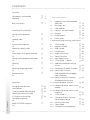
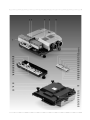
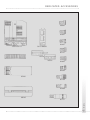
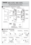
Rolleivision twin MSC 325 P / 535 P
User’s manual
CONTENTS
Contents
Components and controls
Foreword
Brief instructions
Preparing for projection
Setting up the projector
15
Loading slides
16
Inserting the magazine
18
Selecting a specific slide
19
Direct access to a specific slide slot
19
Setting up the projector and screen
20
Focusing
21
Adjusting image registration
22
Remote control
23
Contents
Projection
2
Setting dissolve duration
Laser pointer
Timer-controlled slide changing
Selecting the memo function
27 Displays and warnings
Changing magazines
29
Rollei CM-55/50 magazine
30
»
»
»
3
6
Logging a manually controlled
slide show
1.2
Running a test
1.3
Chip modules
1.3.1 Saving in the chip module
1.3.2 Playback
1.3.3 Miscellaneous
1.4
Direct access
2. Advanced programming techniques
1.1
7
»
»
»
»
»
»
»
»
»
»
»
»
»
»
»
»
1. Programming basics
“Enter mode 1”
Program number
2.1.2 Slide number
2.1.3 Dissolve time
2.1.4 Screen time (timer)
2.1.5 Special functions
2.1.6 Next program line
2.1.7 “Enter mode 1” details
2.1.8 Additional corrections during
test run
2.1.9 Description of special functions
2.1.9.1 Special light functions
Fade/freeze/blink/flash/toggle/
fade-in/fade-out
2.1.9.2 Special mechanical functions
Autoreverse/master-slave
2.1.9.3 Entering special functions
2.1.10 Combining several shows in one
module
2.1.10.2Combining several shows in one
magazine
2.2
“Enter mode 2”
2.2.1 Changing dissolve time with
the IR remote control
2.2.2 Dimming the lamps
2.2.3 Stereo mode
2.2.4 Saving/reactivating projector
2.1
2.1.1
24
25
26
28
»
»
»
»
»
»
»
»
»
»
»
»
»
»
»
»
»
»
»
»
»
»
»
»
»
»
32
33
34
35
35
36
37
38
38
39
39
40
41
41
42
42
43
44
45
45
50
51
52
52
53
54
CONTENTS
3.1 “DiaEdit Win” program
»
55
4. Sync-pulse control
»
55
Helpful hints on slide projection
Standby/pause
The screen
Changing lenses
Sophisticated slide shows
Stereoscopic projection
In case of malfunction
Changing lamps
Care and maintenance
Dedicated accessories
Troubleshooting
Sreen sizes and projection distances
»
»
»
»
»
»
»
»
»
»
»
56
56
57
57
58
59
60
61
64
66
68
Contents
3. Computer control
7
C O M P ONENTS AND CONTROLS
1
2
3
4
5
6
7
8
9
10
11
12
13
14
15
16
17
18
on
19
20
21
22
23
24
25
26
27
28
29
30
31
32
33
34
35
36
37
Slide magazine
Feed heel on slide changer, adjustable
for different magazine types
Slide changer
Cover retaining screw
IR sensor
Cover
Left-hand foot with height adjustment
Interchangeable lenses
Magazine track
Remote tray
IR remote control
»end« button
»timer« button
»dissolve« duration buttons
Manual-focusing and magazineadvance buttons
»stop/go« button
Transmitter diodes
Red LED blinking to confirm transmissiof signal input, also battery check
Green button for forward slide change
Red button for reverse slide change
»memo« button
Rear left foot
Socket for power cable
Master switch
PC control terminal
Sync-pulse/remote-cable terminal
Rear right foot with height adjustment
Chip-module slot
Emergency lever disengaging magazine
drive
Front right foot with height adjustment
Lateral overlap dial
Vertical overlap setscrew
Lamp unit, interchangeable
Mode display
»mode« button
Red »module« button with LED
»+/-« timer buttons with LED
38
39
40
41
42
50
51
»autofocus off« button with LED
Red »enter« button with LED
Numerical keyboard for onboard
programming
Screen-time/dissolve-time/slide/program
no. display
Special functions and projector parameters
Pause light
»Laser pointer« button
Laser exit window
Parts number 43 to 49 in separate
illustrations
43
44
45
46
Battery connector
Chip module
Projection lamp
MT2A/250V fuse for magazine drive and
electronics
47/48 T8A/250V overload fuse for lamps
(MSC 325 P)
49
Lamp-unit release
52
Transit lock
53/54 T10A/250V overload fuse for lamps
(MSC 535 P)
I NTRODUCTION
The Rolleivision Twin MSC 325 P and Rolleivision MSC 535 P are highly precise optoelectronic projectors designed for dissolve
projection. Focusing, magazine advance, slide
changing, dissolve time and screen time are
microprocessor-controlled. A remote infrared
handset with integral timer and dissolve-time
control plus integral laser pointer ensures
high operator comfort. Intelligently organized
indicators keep you informed about the current operating status. The line of interchangeable lenses includes suitable focal lengths for
all normal projection distances.
Either projector accepts LKM, CS and standard magazines, including the Rollei CM-55/
50 hook-up magazines based on the latter.
There is no need to use special magazines
that would require rearranging your slides.
Introduction
Handhabung der Komponenten
Awkward blackout between screen images
and abrupt image changes are a thing of
the past: Projection with smooth transitions
opens up new perspectives for creative slide
shows.
10
We have prepared detailed operating instructions that will enable you to use the full
potential of these unique projectors to best
advantage. An explanation of all important
components and their functions is followed
by brief information on essential controls.
This in turn is followed by a detailed description of use and operating modes of the
projectors. At the end of the instructions, you
will find practical hints as well as troubleshooting help. A table lists screen sizes and
projection distances.
Whether you use your projector in your work
or as a fascinating hobby – we wish you a lot
of fun with dissolve projection.
BR I E F I N S T R U C T I O N S
This section is intended for the hurried reader.
It describes the most important steps for firsttime use of the projector.
Before using the projector for the first
time
»
Loosen cover retaining screw 4, lift off
cover and remove the transit locks 52.
»
Replace the cover and secure.
NOTE: Keep transit locks for later use,
for example, if the projector has to be
shipped for servicing!
52
Connecting the power cable
The projector is designed for operation on
220 to 240V AC. It will automatically set itself
to the available line frequency.
»
Insert power plug in socket 23 and
connect the other end of the cable to a wall
outlet. Set master switch 24 to » - «.
23
24
Brief
CAUTION: Never obstruct the ventilation slits or air outlets! Never use the
projector without its cover in place!
11
BRIEF INSTRUCTIONS
Loading slides (standard magazine, Rollei
CM 55/50)
»
Use uniform slide mounts, preferably
only plastic or only cardboard or glass-mounted slides. Slide mounts made by
are
highly recommended.
Do not use sharp-edged metal or all-glass
mounts!
»
Insert slides upside down, emulsion side
facing the screen, in the required order, starting with slide slot No. 1.
NOTE: The following description
refers to projection with DIN 108
standard magazines or the Rollei CM55/50 magazine supplied with the
projector.
Fitting the lenses
»
Screw in the two lenses without touching
their glass surfaces.
Setting up the projector and screen
»
Brief
Set up the screen so that it is parallel to
the front of the projector with the lenses centered on the screen. Recommended screen
size: 1.5 m x 1.5 m. Projection distance (with
85 or 90mm focal length): 1.5 m or longer
––> Table on pages 68/69.
12
BR I E F I N S T R U C T I O N S
Inserting the standard magazine
»
3
Check position of feed heel on slide
2
16
changer. To do this, first press »stop/go«
button 16, then green button 19. The slide
changer moves out.
»
Use knurled screw to make feed heel 2
horizontal for cardboard or thin plastic slide
mounts.
»
Insert magazine 1 with its numbers
facing outwards until it stops.
1
19
»
Press green button 19. The slide changer
3 feeds the first pair of slides into the projector, the lamps come on automatically, and the
first slide appears on the screen.
Focusing
»
Focus the first slide turning the corresponding projection lens 8.
»
Then press the green button 19. Next,
focus the second slide turning the lens used
for projection. All following slides will then be
focused automatically, but the »focus« buttons 15 remain active for manual override.
38
19
»
15
8
Brief
For manual focusing, press »autofocus
off« button 38. Its red LED lights up. Then use
the »focus« buttons 15 to focus each slide.
13
BRIEF INSTRUCTIONS
Adjusting the image on the screen
»
Center the image on the screen and
adjust it horizontally using the projector feet.
»
To eliminate lateral misalignment, shift
projector or screen in relation to each other.
Adjusting image registration
With a 90mm lens, the screen should be at
least 1.5 m away from the projector.
»
Press green button 19, watch dissolve
and
»
check whether the two images register
perfectly.
32
It is advisable to make this adjustment during
a slow dissolve or after freezing the dissolve
with the »stop/go« button 16. For this adjustment, the slide mounts should preferably be
of identical type.
»
Brief
14
Turn dial 31 for lateral adjustment.
Vertical registration has been set at the factory. However, should a vertical misalignment
be found in spite of the use of identical
mounts, use a screwdriver and turn setscrew
32 to eliminate it.
31
BR I E F I N S T R U C T I O N S
10 43 17
Loading the transmitter battery
»
Lift off the integral remote control 11.
Open battery cover. Align battery connector
43 with terminals of 9V battery and press
down. Replace cover.
11
»
When using the remote control, make
sure to point its transmitter diodes 17 in the
direction of the projector sensor. A minimum
distance of 1 m is required between transmitter and sensor.
»
To replace the remote control, push it
back into its tray 10.
NOTE:
The projector is fully operational even without
a battery in the remote control as long as the
latter is in its tray.
Setting the dissolve duration
16
14
The default dissolve time is two seconds. This
setting is activated when the projector is switched on.
»
To change the dissolve time, press one
of the three buttons 14 marked »dissolve«.
Available settings are 0.1, 3 and 6 seconds.
The corresponding lines indicate the duration
of the dissolve.
19
»
The »stop/go« button 16 may also be
used to freeze a dissolve –> page 24.
The standard dissolve time of 2 seconds is no
longer available after the duration has been
changed.
Brief
20
15
BRIEF INSTRUCTIONS
Slide changing
Forward and reverse:
»
Press green forward button 19 or red
reverse button 20.
With timer:
Insert magazine. Activate screen time
pressing »timer« button 13; to change the
setting, press »+/-«. Upon depression of the
»timer« button, the projector defaults to 8
s. Depression of »+« button sets 12 s, of »-«
button 4 s (MSC 535 P 5 s). Simultaneous
depression of the »+/-« buttons resets the
projector to 8 s.
»
The red »timer« LED blinks as the timer interval is entered.
»
Start timer cycle by pressing the green
forward button 19; the »timer« LED is now
steady.
»
The timer cycle may be interrupted by
pressing the »stop/go« button 16.
»
Brief
To switch the timer off, press »timer«
button 13.
16
37
13
BR I E F I N S T R U C T I O N S
Note displays and warnings
»
18
The red LED 18 on the remote control
blinks each time a command is input.
»
The timer LED 37 signals the status of
automatic timer-controlled slide changing:
LED blinking
LED steady
= Screen time entered or timer
cycle or dissolve interrupted.
= Timer operating.
»
The LED of the »autofocus off« button
38 lights when autofocus is off.
»
The LED of the »module« button 34
signals operations in the »auto« and »record«
modes (–> page 28).
»
The »enter« LED 39 reflects input commands during programming.
»
The LED display 34 shows the different
operating modes. “manual” will appear in the
standard mode (as described here).
»
Other modes can be selected by pressing
the »mode« button 35 (–> page 28).
During standard operation, the display 41
shows slide number as well as dissolve and
screen times (reverse-counting seconds).
Brief
34
35
36
38
37
39
41
17
BRIEF INSTRUCTIONS
Removing the magazine
»
After projection of the last slide, remove
the magazine in forward direction.
»
Brief
12
18
To remove a partly run magazine, press
»end« button 12. The projector completes the
last command received, and the slide changer
returns the loaded slides to their slots. The
magazine is automatically shifted back to starting position and may be removed.
O P E R AT I O N
Before using the projector for the first
time
»
Loosen cover retaining screw 4, lift off
cover and remove the transit locks 52.
»
Replace the cover and secure.
NOTE:
Keep transit locks for later use, for example, if
the projector has to be shipped for servicing!
52
Connecting the power cable
The projector is designed for operation on
220 to 240V AC. It will automatically set itself
to the available line frequency of 50 or 60 Hz.
»
Insert power plug in socket 23 and
connect the other end of the cable to a wall
outlet. Set master switch 24 to » - «.
23
CAUTION: Never obstruct the ventilation slits or air outlets! Never use the
projector without its cover in place!
24
Preparing for projection
The projector is designed for exclusive operation on alternating current!
19
OPERATION
Loading slides
Standard Rollei CM-55/50 magazine
Preferably use “auto-safe” slides in smooth
plastic mounts with rounded corners, no thicker than 3.2 mm. We recommend the use
of
slide mounts that are available in a
comprehensive range of types and sizes.
NOTE:
Bent cardboard-mounted slides, metal mounts
or all-glass mounted slides with sharp edges
or corners should not be used because they
are liable to cause problems.
Identical slide mounts ensure optimum registration of images during the dissolve.
Preparing for projection
CAUTION:
Use only high-quality magazines made
of an opaque material to avoid projector malfunctions!
20
The Rollei CM-55/50 magazines are
a perfect match for the Twin projectors..
These 50-slide magazines are easily hooked
up before or during projection, which permits
continuous projection of several magazines
without any interruption. To aid in this, magazine extension tracks are available as optional
accessories, which are simply hooked into the
projector. Rollei CM-55/50 magazines can also
be used with most other commercially available projectors.
O P E R AT I O N
Loading slides
»
Position the magazine with its numbers
on the right and insert slides upside down,
emulsion facing the screen, in the desired
order, starting with slot No. 1.
LKM magazines
LKM magazines may be used for all slide
mounts up to 2 mm thick. To avoid problems,
we recommend the use of slides between
1.5 and 2 mm thick with LKM magazines.
Mounts of less than 1.5 mm thickness should
be used only with standard magazines. Be
sure to use only identical slide mounts for
optimum registration of images. Magazines
for 60 or 80 slides are commercially available
(not from Rollei).
CS magazines
CS magazines take specially designed CS
mounts. These have shaped edges that engage guides in the slide slots. Other types of
mount cannot be used. CS magazines are
commercially available in sizes for 40 or 100
slides (not from Rollei).
Fitting the lenses
Preparing for projection
Screw the two lenses into their mounts,
taking care not to leave any fingerprints on
their glass surfaces.
21
OPERATION
Inserting the magazine
»
3
2
When using a standard magazine, always
turn the feed heel 2 to its horizontal position
for cardboard-mounted slides or thin plastic
mounts.
»
To do this press »stop/go« button 16
after switching on the projector.
»
Next, press green forward button 19.
Slide changer 3 moves out.
»
Press down knurled screw of slide changer, turn it through 90°, and let go.
»
Press green forward button 19; the slide
changer returns to its original position.
When using LKM or CS magazines
»
Turn the horizontal feed heel to its vertical position.
»
Insert the loaded magazine from behind
in the track, its numbers facing outwards (CS
magazines: numbers facing inwards) as far as
it will go.
»
Preparing for projection
Press green forward button 19; the slide
changer 3 loads the first and second slides
into the projector. The lamp comes on automatically, and projection begins.
22
90°
16 19
O P E R AT I O N
Selecting a specific slide
15 16
If projection is to begin with a specific slide
other than No. 1, the magazine may be
advanced to the desired position.
»
To do this, keep front »focus« button 15
depressed until the corresponding magazine
slot is in the desired position.
19
41
40
1
»
Release the button and press it again to
start normal incremental advance.
»
If you have gone past the slide you want,
run the magazine back in the same way, pressing the rear »focus« button 15.
This special function only works after insertion
of the magazine, before the first slide-change
command is given by pressing button 19 or by
a sync pulse.
Direct access to a specific slide slot
»
Input slide number on numerical keyboard 40. The corresponding number is displayed in 41.
»
Trigger feed command pressing button
19. The projector will start showing the slide
selected.
By entering slide (slot) numbers during projection via the numerical keyboard, slides can
easily be projected in any desired order. When
the next feed command is given, the slide in
position will be changed for the selected one
and dissolved onto the latter.
Preparing for projection
3
23
OPERATION
Setting up the projector and screen
»
Set up the projector properly: its front
parallel to the screen, the lenses centered on
the screen, with adequate space for cables
and magazine travel. A stable horizontal position is very important. We recommend the
use of a projector table. Do not obstruct the
ventilation slits!
Aligning the image
»
Line up the projected image with the
center of the screen. Turn the projector feet
to adjust the height and horizontal position
of the image.
»
To eliminate lateral misalignment, shift
projector and screen in relation to each other.
»
Correct major differences in level between projector and screen exclusively by
raising the projector or its table to avoid keystone distortion of the image.
Preparing for projection
CAUTION:
Do not tilt the projector excessively,
e.g. by raising its front edge beyond
the adjustment range of its feet.
24
O P E R AT I O N
Focusing
»
Focus slide 1 by turning the correspon-
ding lens 8.
38
»
Then press the green button 19 and
focus the second slide by turning the other
lens.
8
This basic manual focusing is required only
once at the beginning of the show. Thereafter,
the autofocus system will take over and automatically focus the two lenses.
Manual refocusing is necessary after changing
the lenses, varying the projection distance or
changing the focal-length setting of zoom
lenses.
Slides in glassless mounts may pop when
exposed to the heat of the light beam. In this
case also, the AF system automatically refocuses the image.
The two »focus« buttons used for manual
operation remain active even with the AF system in operation. In other words, pressing one
of these buttons will override autofocusing.
Blinking of the LED next to button 38 indicates that the image on the screen is being
projected without AF. AF will be reactivated
either by depression of button 38 or by the
next slide-change command. The LED will
then go out.
»
If you wish to project entirely without
AF, press »autofocus off« button 38. Its LED
lights.
Preparing for projection
19
25
OPERATION
Adjusting image registration
»
»
Press green forward button 19.
Watch the dissolve and check whether
the two images register perfectly.
»
It is advisable to make this adjustment
during a slow dissolve or after freezing the
dissolve with the »stop/go« button 16. For
this adjustment, the slide mounts should preferably be of identical type.
»
Turn dial 31 for lateral adjustment. Keep
a minimum distance of 1.5 m.
Preparing for projection
Vertical registration has been set at the factory. However, should a vertical misalignment be
found in spite of the use of identical mounts,
use a screwdriver and turn setscrew 32 to
eliminate it.
26
32
31
O P E R AT I O N
10 43 17
Remote control
»
Leave the IR control 11 in its tray on
the projector if you wish to control the show
directly from the projector.
»
For remote-control operation, remove the
handset from its tray and open its cover.
»
Press the connector 43 onto the terminals of a 9V battery, insert the latter and close
the cover.
»
When using the remote control, make
sure to point its transmitter diodes 17 in the
direction of the projector sensor. A minimum
distance of 1 m is required between transmitter and sensor.
»
After the show replace the remote control, pushing it back into its tray 10.
CAUTION:
To avoid malfunctions, the IR sensor 5
must not be exposed to bright light,
such as from a lamp or direct daylight.
NOTE:
Before connecting a cable remote control to
terminal 26, remove the IR remote control
from its tray.
Preparing for projection
11
27
OPERATION
Setting dissolve duration
The default dissolve time of the projector is
16
14
two seconds. This setting is activated when
the projector is switched on.
»
To change the dissolve time, press one
of the three buttons 14 marked »dissolve«.
Available settings are 0.1, 3 and 6 seconds.
The dissolve time entered is displayed on 41.
(For assigning different dissolve times to the
buttons, –> page 52, item 2.2.1.)
»
The »stop/go« button 16 may also be
used to freeze a dissolve
20
19
»
and to resume dissolve by pressing it
again. The default time can then no longer be
activated.
Forward slide change:
For each forward slide change
briefly press green button 19 once.
»
Reverse slide change:
For each reverse slide change, e.g. for repeating a slide already shown,
briefly press red button 20 once.
Projection
»
28
NOTE:
Single slides can only be projected with a
magazine inserted, since the latter also has a
control function.
If you re-sort or temporarily remove
slides from the magazine during a
show, be sure to keep the two empty
slots free – this is where the projector
must return the slides actually being
projected!
O P E R AT I O N
Laser pointer
»
Press button 50 on the side of the remo-
te control to switch on the laser pointer built
into the handset.
The pointer is supplied with power by the 9V
battery in the handset.
51
NOTE:
Laser power corresponds to Class II. The figure 51 points to the exit window of the laser.
Projection
50
CAUTION:
Note that laser beams can harm your
eyesight!
Therefore:
– Never look into the light-exit opening at the front of the remote set
when the pointer is on.
– Never direct the pointer at the eyes
of another person.
– Always keep the laser pointer out
of reach of children.
29
OPERATION
Timer-controlled slide changing
»
Activate the automatic screen time by
briefly pressing the »timer« button 13.
»
Start the cycle by pressing the green forward button 19.
To vary the screen time, proceed as follows:
Screen time after depression of button 13 is
8 s.
»
Depression of the »+« button changes
the setting to 12 s. Depression of the »-«
button sets an interval of 4 s (MSC 535 P 5 s).
Simultaneous depression of the »+/-« buttons
resets the timer to 8 s.
»
To switch off the timer, press »timer«
button 13.
If the screen time is set with the buttons 37,
the red timer LED will at first blink red and
then light steady when the projector is started
with the green forward button 19.
The screen time entered and the number of
the projected slide are displayed on 41.
»
Timer intervals can easily be cut short by
pressing the forward button 19 and will then
resume normally.
Projection
»
30
Depression of the red reverse button 20
clears the timer and loads the previous slide
back into the projector. To go back to automatic timing after such a reverse slide change,
reset the timer.
37
13
O P E R AT I O N
Selecting the memo function
21 19
With the »memo« button 21, up to 16 slides
in a magazine can be electronically flagged for
repetition after the run.
»
To do this, briefly press the »memo«
button 21 each time a slide to be repeated
appears on the screen.
Once the magazine has completed its run, the
projector will automatically show the first slide
so selected.
»
To recall each of the remaining flagged
slides, press the green button 19.
During projection of the flagged slides, the
LED display 34 will show »test«, reflecting
operation of the working memory.
NOTE:
Automatically recalling the slides under timer
control is not possible.
Projection
34
31
OPERATION
Displays and warnings
»
18
LED 18 on the remote control lights up
for each input command.
»
The »timer« LED 37 signals the status of
automatic timer-controlled slide changing:
LED blinking = Screen time set or timer cycle
or dissolve interrupted.
LED steady
37
36
38
34
41
= Timer operating.
The display 34 indicates the different operating modes.
manual =
Standard operation
test =
Commands entered are executed
automatically via the working
memory.
auto =
record =
Automatic execution of program
from chip module.
Recording mode; program stored
in working memory may be loaded into chip module.
During standard operation, the LED display
41 informs about slide number as well as dissolve and screen times.
Projection
Timer operation is indicated by the reversecounting second counter.
32
In the enter modes 1 and 2 (programming),
the program number and the special-function
(SF) ID number as well as the projector parameters (PP) are also displayed (–> page 41).
The »autofocus off« LED 38 lights when
autofocus is off.
In the »auto« and »record« modes, the red
»module« LED 36 signals that a command
has to be entered with the »module« button.
In the enter modes 1 and 2, the »enter«
LED 39 signals that the projector is ready for
programming via the numerical keyboard (–>
pages 42 and 52).
O P E R AT I O N
Changing magazines
19
The magazine has completed its forward or
reverse run:
»
Pull magazine out from front or rear of
projector. Insert new magazine.
»
Continue show pressing green forward
button 19.
Changing a magazine before the end of its
run:
»
Press »end« button 12. The projector
completes the last command, and the slide
changer returns the slides in the projector to
their magazine slots. The magazine automatically returns to starting position and may be
removed. All commands are cleared.
CAUTION:
When using different types of magazine (standard, LKM, CS), make sure
that the feed heel is in the correct
position! (–> page 18)
Only insert or remove the magazine
when the projector is switched on!
Projection
12
33
OPERATION
Using Rollei CM-55/50 magazines
To ensure smooth attachment and removal of
Rollei CM 55/50 magazines during projection,
observe the following:
»
Push the first magazine forward as far as
it will go and start magazine advance.
Attach the second magazine not later than
during projection of slide 45 of the first magazine. The first magazine may be detached
after slide No. 6 of the second magazine, but
not later than slide No. 12.
»
To do this, slightly raise the magazine
and lift it out.
If a track extension is used, the first magazine
may be detached later.
»
To attach a track extension, engage its
studs into the corresponding holes 9 of the
magazine track where they are engaged by
the force of springs.
Projection
CAUTION:
Even with the track extensions in place,
never have more than two magazines
on the track at any time.
Rollei CM-55/50 magazines can also be
used on their own as standard magazines on any projector designed to take
this type of magazine.
34
9
35
PROGRAMMING
1.1 Logging a manually controlled slide
show
Unnoticed by the user, the projector will
automatically log the slide data in its working
memory during a normal slide show. These
include: Slide number as well as dissolve and
screen time, which are logged under a common program number. If a dissolve time is
changed by pressing one of the three dissolve
buttons 14, this will be logged during the following dissolve. The timer interval recorded is
always equivalent to the screen time of a slide
between the end of its fade-in and the beginning of its fade-out.
»
In the timer mode, the show can be
stopped and continued by pressing the »stop/
go« button 16. The resultant extended screen
time will be recorded.
»
Dissolves also can be stopped with the
aid of the »stop/go« button. However, this
will not be logged.
Basics
NOTE: Logged data will be lost if the projector is switched off.
36
PROGRAMMING
A manually controlled slide show can immediately be repeated automatically for testing
purposes.
»
To do this, switch on the »test« mode
by pressing the »mode« button 35 after the
end of the show.
»
Playback can be started immediately by
pressing the green forward button 19.
»
Use the »stop/go« button 16 to stop
and restart a dissolve or the timer.
»
The show can be terminated at any time
by pressing the »end« button 12.
The »memo« button 21 can be activated as
in the manual mode.
Making corrections during a test run
It is often necessary to change the dissolve or
screen time of a slide.
»
To do this, press the »stop/go« button 16
during the test run while the corresponding
slide is being shown.
»
If the timer-correction button 37 or
one of the three dissolve buttons 14 is then
pressed, this will change the previously recorded screen time of the slide being shown or
the dissolve duration from this to the next
slide.
»
If, however, the dissolve time being
watched is to be corrected, first press the red
reverse button before making the correction.
Additional reverse commands are, however,
impossible during test runs.
»
To resume the show, press the green forward button 19 or the »stop/go« button 16.
Basics
1.2 Running a test
37
PROGRAMMING
1.3 Chip modules
A slide show logged in the program storage
of the projector can be permanently saved
in an interchangeable chip module 44. The
slot for this module is located underneath the
control panel.
Modules are available with a capacity of
approx. 120 slides (module 100) or approx.
400 slides (module 300). The capacity may
vary depending on the slide information
involved. All modules can be read and overwritten as often as desired. In each case the
entire contents of the module is loaded into
the projector‘s program storage or the latter‘s
content into the type 100 or 300 module
(insofar as this is possible).
Basics
NOTE: Standard equipment of the projector is
a type 100 module.
38
44
28
PROGRAMMING
1.3.1 Saving in the chip module
When saving a show in the module, the data
logged in the working memory of the projector are transferred to the module.
»
To do this, press the »mode« button 35
to set the »record« mode. The LED of the
»module« button 36 will blink.
»
1.3.2 Playing back a show saved in the
module
To play back a show saved in a module it is
necessary to transfer its data into the working
memory of the projector.
»
To do this, set the »auto« mode by pressing the »mode« button 35. The LED of the
»module« button 36 starts blinking.
After pressing the »module« button 36,
the word »record« will also blink, signaling
that any further depression of the »module«
button will completely erase the information
stored in the module.
»
»
»
The logged data are transferred to the
module after the second depression of the
»module« button. During this process, the
LED of the »module« button 36 is lit. It will
go out as soon as the recording is complete,
and the projector will automatically switch
to the »test« mode. The data of the show
remain logged in the working memory.
If there is no module in the slot, the LED will
keep blinking.
After depression of the »module« button 36, a copy of the data in the module will
be transferred from the latter to the working
memory.
The show can be started immediately by
pressing the green forward button 19.
»
Using the »stop/go« button 16, dissolves
or the timer can be stopped and restarted.
»
The »memo« button 21 can be activated
as in the manual mode.
»
The show can be terminated at any time
by pressing the »end« button 12.
The »module« LED will also blink if the capacity of the module is insufficient. However,
the show has been saved as far as possible.
»
In this case, quit the »record« mode by
pressing the »mode« button 35.
Basics
NOTE: Do not switch off the projector during
saving!
39
PROGRAMMING
1.3.3 Miscellaneous
The »test« and »auto« modes are similar.
Basics
The only difference is that corrections can be
made in the »test« mode and that module
data can be loaded down from the module in
the »auto« mode.
40
PROGRAMMING
1.4 Direct access to specific slides in the
»auto« and »test« modes
As in the »manual« mode, direct access to all
slides in the working memory is also possible
in the »test« and »auto« modes. The run can
be started in three different ways:
»
»
1. By pressing the green forward button.
2. By accessing a slide slot using the
»focus« buttons 15 and then pressing the
green forward button 19.
»
By entering the number of the slide slot
on the numerical keyboard and pressing the
green forward button 19.
The projector will then search for the program number under which the selected slide
number is logged. This and the slide registered under the following program number will
be moved into the projector.
NOTE:
Direct access is possible in the »auto« and
»test« modes only if the slide selected does
exist in the working memory.
NOTE:
An uninterrupted show of over 100 slides can
be assembled only with type CM 55/50 Rollei
hook-up magazines. If such a show is to start
with slide (slot) number 175, for example,
first enter the figure 175 via the keyboard
and then press the green forward button 19.
As a result, the magazine will not advance by
175 slide slots, but only by 25 - the projector
assuming that the magazine with slides 151
to 200 is in place. The projector will start
operating that way beginning with slide (slot)
number 101.
»
Basics
During a slide show, direct access is possible at any time using the keyboard and then
pressing the green forward button 19.
In this case, the slide in the standby position
is exchanged for the one selected and then
faded in.
41
PROGRAMMING
2.1 Programming a slide show with the
aid of “enter mode 1”
2.1.1 Program number
Input via the keyboard offers a much greater
number of possibilities for assembling a slide
show. In this case, it is not necessary to run
the show in parallel, as has been described
under 1.1. In addition, –> special functions
can be programmed as well.
ting you to enter the program number via the
keyboard 40. It is advisable to start the program with number 1. After input, press the
»enter« button 39. This transfers the selected
number to the working memory where it is
logged. The highest program number is 999.
In other words, a show may include up to
999 slides.
Setting up a table like the one shown on
page 46 is helpful because it allows one
line of the program after another to be processed. “Enter mode 1” is used for programming.
For this purpose,
select the »test« mode using the
»mode« button 35
»
»
Advanced programming techniques
and press the »enter« button 39.
The slide show can now be entered with all
desired special effects.
42
»program« blinks in the display 41, promp-
PROGRAMMING
2.1.2 Slide number
2.1.3 Dissolve time
After transfer of the program number, »posi-
After transfer of the program number, »posi-
tion« will now blink in display 41. The digit
field shows the slide (slot) number previously
entered under this program number.
tion« will now blink in display 41. The digit
field shows the dissolve time previously entered under this program number. When programming a new show, the default dissolve
time of 2.5 second is prompted.
To accept this time, press »enter« button
39.
»
To input a different number, use the
keyboard
»
and press »enter« button 39 to log it
in the working memory. The highest possible
slide number is 999.
»
To accept this time, press »enter« button
39.
»
To input a different time, use the keyboard and confirm by pressing »enter« button 39.
Any dissolve duration between 0.1 s (cut) and
25 s may be chosen.
Advanced programming techniques
»
43
PROGRAMMING
2.1.4 Screen time (timer)
Upon transfer of the dissolve time, »timer«
will blink in display 41. The digit field shows
the screen time previously entered under
this program number. When programming a
new show, the default timer interval of »0«
second will be prompted - in other words,
the timer is inoperative.
To accept this interval, press »enter«
button 39.
»
»
To input a different interval, use the
keyboard and confirm by pressing »enter«
button 39.
Timer intervals can only be input in increments of full seconds.
When the timer is inoperative, the forward
command is either given by pressing the
green forward button 19 or by the forward
command from the sync-pulse generator or
the computer. Screen time can be set in steps
of one second from 4 s (MSC 535 P 5 s) to
600 s. It should not be shorter than the time
required for slide changing (longer in the case
of far-distant slides).
Advanced programming techniques
»
After pressing the »enter« button 39,
the interval displayed will be transferred to
the working memory - 7.0 seconds in our
example.
»
44
NOTE:
The display will always show the timer interval in full seconds. In other words, a timer
interval of, say, 7.8 s previously saved in another mode will be shown as 7 seconds.
To avoid accidental change of the timer
interval, do not press the »enter« button 39,
but the »timer(+)correction« button 37 to
activate the timer (–>2.1.7).
PROGRAMMING
2.1.5 Special functions
2.1.6 Next program line
After transfer of the screen time, »SF« will
After all the parameters (slide slot number,
now blink in display 41.
dissolve time, screen time and special function) have been entered for a slide, »position« will again blink in the display, and the
next-higher program number will appear.
The digit field shows the program number of
the special function previously recorded.
When programming a new show, special
function »0.0.0« will be prompted. In other
words, no special function will be used.
If the slide is to be projected without any special function,
»
The information for the next program line
(program step) can now be entered.
To correct slide information anywhere within
the program, overwrite the program number
displayed using the keyboard and confirm by
pressing »enter« 39.
press the »enter« button 39.
–> To continue, see 2.1.1.
To enter another special function,
»
»
use the keyboard
and confirm by pressing »enter« button
39.
The possibilities afforded by the special functions is described in detail under 2.1.9. To
enter one of the special functions listed in the
corresponding table,
39.
use the keyboard
and confirm by pressing »enter« button
Advanced programming techniques
»
»
45
PROGRAMMING
2.1.7 “Enter mode 1” details
With the aid of the timer-correction buttons
37 the program may be checked line by line,
with the green forward and the red reverse
button2 19/20 column by column.
Errors should immediately be corrected by
overwriting before pressing the »enter« button 39.
Should the error be detected only after
depression of »enter« button 39,
»
press »timer(-)correction« button 37,
until the same letter field is blinking again.
»
»
Then enter the desired information.
Always confirm any change or new entry
by pressing the »enter« button 39.
Advanced programming techniques
NOTE:
Any numerical input followed by depression
of the »end« button 12 or the »mode« button 35 will be lost.
46
»
To quit the “enter mode 1”, simply press
the »end« button 12 or the »mode« button
35.
2.1.8 Additional corrections during test
run
In the »test« mode, the “enter mode 1” may
be used to make changes in a current show
via the keyboard. Slide data may be changed
at will. These include slide number, dissolve
time, screen time and special functions. The
changes are logged in the working memory.
»
To do this during the show, press the
»stop/go« button 16 in the »test« mode.
The “enter mode 1” is active after the
»enter« button has been pressed.
»
Next, select the program number (line)
that is to be changed. To aid your orientation, the currently active program number is
shown.
»
Confirm the (new) program number by
pressing »enter« 39. The slide (slot) number
entered under this program number appears
and may be changed.
After depression of »enter« 39, the dissolve
time, etc., appear in the display.
»
Terminate the change by pressing the
»end« button 12
»
and resume the show by pressing either
the »stop/go« button 16 or the green forward button 19.
PROGRAMMING
2.1.9 Description of special functions
The term “special function” covers all functions other than standard dissolve of one
slide onto another. It always refers to the slide
under which the function is entered. There
are special light functions and special mechanical functions.
Mechanical functions
0 Normal slide change
1 Autoreverse
2 Slave pulse at beginning
of a dissolve
4 Slave pulse roughly in the
middle of a dissolve
Function 1 can be combined with
functions 2 or 4 by entering the
the corresponding sum.
Light functions
*0 Normal dissolve
*1 Fade-in/sandwich
*2 Freeze
*3 Blinking
*4 Flashing
5 Toggling
*6 Fade-out of previous
program step/fade-in of
slide of current program
step
*7 Fade-out of slide of previous
program step / pause /
continue with slide of
current program step
by pressing forward
button.
Number / Duration
—
1 sec
...9s
1 sec
...9s
1x
...9x
1x
...9x
1x
...9x
* Only light functions
0, 6 and 7 can be combined
with the mechanical
functions.
Advanced programming techniques
Special functions
47
PROGRAMMING
2.1.9.1 Special light functions
Fade-in/sandwich
Flashing
In the »test« and »auto« modes, a slide with
the „fade-in“ special function entered in
its program line will be faded into the slide
already being projected in the other projector
channel with full brightness. The screen time
of the fade-in slide can be selected between
1 and 9 s. The fade-in and fade-out times will
depend on the dissolve time entered for that
slide. The timer interval programmed for the
slide gives the screen time of the slide in the
other channel after the end of the fade-in
function.
–> Blinking – reduced duration.
Advanced programming techniques
Freeze
In the »test« and »auto« modes, a slide with
the „freeze“ function entered in its program
line will be stopped in mid-dissolve. The
freeze time can be chosen between 1 and 9
seconds.
48
Blinking
In the »test« and »auto« modes, a slide with
the „blinking“ function entered in its program line will be faded in blinking into the
slide being projected in the other projector
channel with full brightness. The number of
blinking cycles may be chosen between 1 and
9. The duration of fade-in/fade-out depends
on the dissolve time entered for the fade-in
slide, but should be kept brief in order to
preserve the impression of blinking. The timer
interval selected gives the screen time of the
slide in the other channel after the end of the
blinking function.
Toggling
In the »test« and »auto« modes, a slide with
the „toggling“ function entered in its program line will be projected alternately with
the slide already on the screen. The number
of toggling cycles can be varied from 1 to
9. The toggling characteristics can be varied
with the aid of the dissolve time entered. The
timer interval selected gives the screen time
of the slide in the other channel after the
end of the toggling function. The toggling
cycle always ends with the slide in the other
channel.
Fade-in/fade-out
In this function, the previous slide will first
fade out completely before fading in again.
This is useful if two slides should not be
dissolved, for instance when changing from
horizontal to vertical format.
Fade-out – pause – fade-in
This function may be selected if the show is
to be interrupted. The previous slide is faded
out. The next slide is faded in and the show
resumes only after renewed depression of the
green forward button.
PROGRAMMING
2.1.9.2 Special mechanical functions
Autoreverse
NOTE: To avoid malfunctions, make sure that
In the »test« and »auto« modes, a slide with
the „Autoreverse“ function entered in its
program line will automatically be followed
by the first slide of the show. The transition
will be seamless, in other words, there will be
no blackout.
the slave projector has completed its dissolve
or special function before a slave command
is given.
Advanced programming techniques
Master-slave operation
In the »test« and »auto« modes, a slide with
one of the two „master-slave“ functions
entered in its program line will cause a control pulse to be applied to the PC terminal.
With a Rollei adapter cable connected to the
remote-control terminal (RC terminal) of another MSC 325 P, MSC 535 P, MSC 300 MSC
300 P, MSC 320 S or MSC 330 P, this may be
used to trigger a forward pulse in a slave. The
pulse may be applied either at the beginning
or in the middle of a dissolve. If the slave also
is a type MSC 325 P, MSC 535 P, MSC 330
P or MSC 300 P projector, this may execute
special functions and can in turn be used as a
master driving an additional slave. Depending
on its operating mode, the latter will use the
dissolve times and, possibly, special functions
either according to the dissolve time set on
its keyboard (manual mode) or the data in its
working memory (test or auto mode). A certain triggering delay is, however, unavoidable
in a ladder network.
2.1.9.3 Entering special functions
See page 43, top.
49
PROGRAMMING
Sample program
Program-No.Slide-No.
Dissolve
Timer
Special
function
Comments
1
5
5.0
09
000
000 need not be entered if
»enter« is pressed.
2
6
2.5
06
000
3
7
0.5
10*
043
4
9
3.0
08
000
5
3
1.5
16**
018
Fade slide 3 into slide 9 for 1.5 s.
Fade-in duration 8 s.
** screen time of slide 9 after end
of fade-in.
6
6
1.0
20***
054
Toggle slide 6 four times with slide 4.
*** screen time of slide 9 after end of
toggling.
7
1
0.5
09
028
Freeze dissolve of slide 9 onto slide
1 for 8 s.
8
2
2.0
06
060
Fade out slide 1, then fade in slide 2.
9
3
1.0
05
100
Autoreverse dissolve of slide 3 onto slide 5
(then start of program) with dissolve time
Flash slide 7 three times into slide 6. Brief
flash duration of 0.5 s. Dissolve time
* screen time of slide 6 after
end of flashing.
of slide 5.
Enter special function »000« (none) if the show is to stop after program number 9. Slide 3 will then
automatically be faded out for 2.0 s. If another fade-out duration - e.g. 5.0 s - should then be
desired, add program line 10 in which only the fade-out time need be entered.
Example
09
10
50
3
0
1.0
5.0
5
0
000
000
Slide 3 fades out for 5.0 s.
PROGRAMMING
Entering an example:
Use »mode« button to select »test«
enter
-> Program No. 1 is
prompted
enter
-> ... accepted,
slide no. is prompted
5
-> overwrite with slide no. 5
enter
-> accepted,
dissolve time is prompted
5-0 -> overwrite with 5.0 seconds
enter
-> accepted,
timer interval is prompted
9
-> overwrite with 9 seconds
enter
-> accepted,
special function is prompted
enter
-> unchanged, previous
value (here »000«) is taken over
Program 2 is prompted
»
enter
accepted,
-> program number
slide no. is prompted
6
-> overwrite with slide no. 6
enter
-> accepted,
dissolve time is prompted
2-5 -> overwrite with 2.5 s
enter
-> accepted,
timer interval is prompted
6
-> overwrite with 6 seconds
enter
-> accepted,
special function is prompted
enter
-> unchanged, the previous value (here »000«) is taken over
Program 3 is prompted
enter
-> program number
accepted,
slide no. is prompted
»
»
»
»
»
»
»
»
»
»
»
»
»
»
»
»
7
-> overwrite with slide no 7
enter
-> accepted,
dissolve time is prompted
0-2 ->overwrite with 0.2 second
enter
-> accepted,
timer interval is prompted
1-0 -> overwrite with 10 seconds
enter
-> accepted,
special function is prompted
0-4-5
-> overwrite with special
function „Flashing“ (5x)
enter
-> accepted
Program 4 is prompted
»
enter
accepted,
»
»
»
»
»
»
»
-> program number
slide number is prompted
9
-> overwrite with slide number 9
enter
-> accepted,
dissolve time is prompted
3-0 -> overwrite with 3 seconds
-> accepted,
timer interval is prompted
8
-> overwrite with 8 seconds
enter
-> accepted,
special function is prompted
enter
-> unchanged, previous
value (here »000«) is taken over
Program 5 is prompted
»
enter
enter
accepted,
»
»
»
»
-> program number
slide no. is prompted
3
-> overwrite with slide no. 3
enter
-> accepted,
dissolve time is prompted
1-5 -> overwrite with 1.5 second
enter
-> accepted,
Example
»
»
»
»
»
»
»
»
»
»
51
PROGRAMMING
»
»
»
»
timer interval is prompted
16 -> overwrite with 16 seconds
enter
-> accepted,
special function is prompted
0-1-8
-> overwrite with “Fadein” special function (8 s)
enter
-> accepted
Program 6 is prompted
»
»
»
»
enter
accepted,
enter
accepted,
-> program number
slide no. is prompted
6
-> overwrite with slide no. 6
enter
-> accepted,
dissolve time is prompted
1-0 -> overwrite with 1.0 second
enter
-> accepted,
timer interval is prompted
20 -> overwrite with 20 seconds
enter
-> accepted,
special function is prompted
0-5-4
-> overwrite with “Toggling” special function (4x)
enter
-> accepted,
Program 7 is prompted
»
»
»
»
»
»
»
»
»
Example
enter
accepted,
52
»
»
»
»
»
-> program number
slide no. is prompted
1
-> overwrite with slide no. 1
enter
-> accepted,
dissolve time is prompted
0-5 -> overwrite with 0.5 second
enter
-> accepted,
timer interval is prompted
9
-> overwrite with 9 seconds
enter
-> accepted,
special function is prompted
0-2-8
-> overwrite with “Freeze” special function (8 s)
enter
-> accepted,
Program 8 is prompted
»
-> program number
slide no. is prompted
2
-> overwrite with slide no. 2
enter
-> accepted,
dissolve time is prompted
2-0 -> overwrite with 2 seconds
enter
-> accepted,
timer interval is prompted
6
-> overwrite with 6 seconds
enter
-> accepted,
special function is prompted
0-6-0
-> overwrite with “Fadeout/fade-in” special function
enter
-> accepted,
Program 9 is prompted
»
»
»
»
»
»
»
»
»
enter
accepted,
»
»
-> program number
slide no. is prompted
3
-> overwrite with slide no. 3
enter
-> accepted,
dissolve time is prompted
PROGRAMMING
1-0 -> overwrite with 1.0 second
enter
-> accepted,
timer interval is prompted
5
-> overwrite with 5 seconds
enter
-> accepted,
special function is prompted
1-0-0
-> overwrite with „Autoreverse“ special function
enter
-> accepted,
Program 10 is prompted
»
»
end -> End of program
The programmed slide show can now be
started by pressing the green forward button.
It is advisable to save the program by transferring it from the working memory to a chip
module (-> module).
NOTE:
It is highly recommended that long slide
shows be programmed in sections and saved
in a chip module.
»
To do this, terminate programming by
switching from the »test« to the »record«
mode using the »mode« button. The program can then be saved in a module as previously described.
»
»
Next, switch back to the »test« mode
and press the »enter« button again. Programming can now be resumed
»
by selecting the next program number.
The previous data will remain in the working
memory and have not been changed in any
way by saving. If the projector is switched off
in between, the contents of the module will
have to be loaded into the working memory
of the projector before resuming programming.
Slide shows programmed with the previous
Rolleivision 35 Twin Digital / P can be played
back and edited with the Rolleivision MSC
325 P, MSC 535P, MSC 300 P, MSC 330 P.
The opposite, however, is not possible.
Example
»
»
»
»
»
»
53
PROGRAMMING
2.1.10 Several slide shows in one module
shows might look as follows:
2.1.10.1 Slide shows in several magazines
If a show is started with a slide (slot) number
of 1, 101, 151, 201, 251, 301, 351, 401 ...
951, it will always begin with the first slide
of the corresponding magazine. This may be
used to save several slide shows in one chip
module. It should be noted, however, that
the projector will always save the entire contents of its working memory in one module.
Consequently, if a new show has to be
expanded, the old shows will first have to be
loaded down from the module into the working memory. A combination of several slide
Show 1:
Show 2:
Show 3:
Saving in a module
Show 4:
54
Program No.
Slide No.
1
1
2
2
3
3
.
.
.
.
36
36
37
0 !!
38
101
39
102
40
103
.
.
.
.
59
122
60
0 !!
(Slide sequence
may also be irregular!)
61
151
62
162
63
195
64
155
.
.
.
.
114
205
115
0 !!
116
251
117
255
.
.
.
.
293
442
294
0 !!
PROGRAMMING
2.1.10.2 Several shows in one magazine
Note: To allow subsequent program expansion of the different shows, some gaps should
be left in the current program numbers.
However, these should not be too large
because they use up module space.
Program No.
Slide No.
Show 1:
.
.
.
.
36
36
37
0 !!
Show 2:
70
71
72
.
.
91
92
101
102
103
.
.
122
0 !!
There may also be several shows in one
magazine. Each starting slide should be selected via the keyboard upon starting.
Program no.
Slide No.
Show 1:
1
1
2
2
3
3
4
4
5
0 !
Show 2:
6
16
7
17
8
18
9
19
10
20
11
0 !!
Show 3:
(The data sequence may also
be irregular, and it is even
possible to use slides from
preceding shows. However,
starting slides may not be
used in any other show.)
12
13
14
15
16
17
25
29
3
17
20
0 !!
Saving in a module
It should be noted that every show has to
end with a »0« slide number. In the case of
irregular slide sequence, slide numbers must
not be lower than the number of the starting
slide.
55
PROGRAMMING
2.2 Enter mode 2 (varying projector
parameters)
2.2.1 Varying dissolve time with the IR
remote control
“Enter mode 2” permits factory settings to
be varied. These include the dissolve times of
two of the three dissolve buttons, the brilliance of the projection lamps and the stereo
mode. The corrected parameters have to be
saved and reactivated as needed, because
the projector will revert to its factory settings
every time it is switched on.
The medium and long dissolve times can be
varied over a range of 1 – 25 s in steps of
one second.
»
»
2xx
3xx
»
and press the »enter« button 39. The
information “PP” (projector parameter)
appears in display 41.
»
Depression of the »enter« button will
transfer a changed value to the projector,
automatically terminating “enter mode 2”.
The mode display changes from »record« to
»manual«.
Projector
The first figure entered on the keyboard
selects the dissolve button. Then enter two
digits for the dissolve time
To set “enter mode 2”,
select the »record« mode using the
»mode« button 35
56
»
and save it by pressing the »enter« button 39.
“medium” dissolve button
“long” dissolve button
PROGRAMMING
2.2.2
Adjusting basic projection-lamp brilliance
MSC 325 P:
MSC 535 P:
Basic lamp brilliance can be reduced.
»
The MSC 535 P has an additional boost mode
allowing basic brilliance to be increased, if
necessary.
»
»
Note:
400
100%
410
90%
420
80%
440
70%
480
»
Brilliance
Brilliance
The boost mode may shorten lamp life.
The following tables give approximate values
and differ only by selection of a volatile or
non-volatile memory.
481
50%
When switching the projector on, the
default setting is always 100%.
Brilliance
80%
482
90%
483
100%
484
Brilliance
approx. 110%
(boost mode)
» When switching the projector on, the
default setting is always 100%.
491
80%
492
90%
493
100%
494
»
Brilliance
Brilliance
approx. 110%
(boost mode)
The value selected will remain locked in
memory even if the projector is switched off.
Projector
Entering the figure 1 on the numerical
keyboard selects the dimmer mode of a volatile memory.
Enter a two-digit dimmer value
and confirm by pressing »enter« 39.
The following table gives approximate output
values.
57
PROGRAMMING
2.2.3 Stereo mode
To switch the projector to stereo mode,
»
»
enter the figures 5-0-1
To save the selected projector parameters for
later use (beyond switching the projector off),
and press the »enter« button.
»
»
To quit the stereo mode,
enter 5-0-0
»
»
and press the »enter« button 39.
In the stereo mode, two slides are projected
at a time with full lamp power. To protect
the linear polarizing filters from excessive
heat, stereoscopic projection is limited to one
minute per slide pair.
»
To project another slide pair, press the
green forward button 19.
»
Pressing the »memo« button 21, up to
eight discrete slide pairs can be repeated after
the show.
Projector
No special functions (except for master-slave
pulses) are available in stereo mode.
58
2.2.4 Saving/reactivating projector parameters
enter the figures 0-0-2
and press the »enter« button 39.
To reactivate the selected parameters after
switching on the projector,
»
»
»
select “enter mode 2”,
enter the figures 0-0-1
and press the »enter« button.
PROGRAMMING
3.1 “DiaEdit Win”
4. Sync-pulse control
The Rollei “DiaEdit Win” software has been
The projector has a special terminal (26) for
developed especially for IBM-compatible PCs
and serves to simplify the assembly even of
sophisticated slide shows. It allows the slide
information required, such as program number, slide (slot) number, dissolve time, screen
time and special functions, to be presented
on the screen in tabular form for editing. The
course of the show can easily be followed on
the screen, interrupted and terminated at will.
The programs can be downloaded into a PC
or into a chip module and can be reloaded at
any time. Printing and copying (partial) programs onto each other are additional features
of “DiaEdit Win”.
this purpose. The following equipment is
recommended for sound recording:
--> GEBUHR DIA-AV Recorder
--> KINDERMANN AV Stereo Radio Recorder.
These are stereo recorders with a freehead
track and integral sync-pulse generator for
projector control. The Rollei Adapter Cable
83 881 is needed for connecting the recorder
to the projector. The cable is connected to
terminal 26 of the projector. It is 1.5 m long.
Other suitable equipment is made by Fostex,
Tascam and Yamaha.
These units use an external sync-pulse generator, such as the Rollei RCP Slide Synchronizer 62 656. Be sure to follow the instructions
supplied with these units.
NOTE:
Since the feed pulses are generated by the
sync-pulse generator or AV recorder, timer
intervals have to be deleted from programmed shows!
»
Projector
To do this, press the »timer« button in
the »record« mode. It is advisable to delete
the timer intervals before saving the show in
the chip module.
59
HELPFUL HINTS ON SLIDE PROJE C T I O N
Standby/Pause
The screen
At the start of a show, the first two slides
is a decisive factor in determining the quality
have to be moved into the projector from the
magazine before the first fade-in. The corresponding delay can be avoided only if the
slides are moved into position beforehand.
of your projected images. A tensioning device
taking creases out of the screen is very desirable. Larger screens mean greater impact.
»
»
The larger the screen, the more impressive the
projected image.
To do this, press »stop/go« button 16,
followed by green forward button 19.
The first two slides are loaded into the projector.
Fade-in will follow only when the green forward button is pressed the next time. The
»timer« LED will blink during waiting.
The forward commands may also be given
by the sync-pulse generator or the computer.
Standby operation is also possible if a discrete
slide in the magazine is to be accessed directly via the keyboard.
»
Set the screen up vertically (and parallel
to the front of the projector). The center of
the screen should be at the same height as
the projection lenses and about 25 cm above
the audience‘s eye level.
In very large rooms alignment is easier if
you tilt the top of the screen about 5 - 10°
towards the projector.
»
»
In small rooms it may be helpful to set up
the projector in an adjacent room and project
through an open door.
»
To resume the show, press the forward
button.
Hints
Select a large-enough screen - about 1.5
m y 1.5 m for home projection. Screens of
1.8 m
x 1.8 m to 3 m x 3 m are suitable for large to
very large rooms.
During projection in the manual mode (timer
disabled), the slide show may be interrupted.
To do this, press the »stop/go« button,
followed by the green forward button.
The current slide fades out, and the pause
light comes on.
60
»
NOTE:
The table on pages 68/69 gives screen sizes
and projection distances for different lenses.
HELPFUL HINTS ON S L I D E P R O J E C T I O N
»
»
Unscrew the lenses by turning them
counterclockwise.
Clean the glass surfaces of two lenses of
matching focal length and screw them into
the projector.
Repeat basic manual focusing.
»
Zoom lenses with focal lengths between
70 and 120 mm are useful for projection in
rooms of different size and make it easier to
match the slide size with the screen size.
Rollei AV-Apogon and Schneider-Kreuznach
AV-Xenotar lenses meet the most stringent
demands for edge sharpness, uniform illumination and color balance. They are renowned
as high-performance slide-projection lenses
bringing to the screen the outstanding image
quality of modern camera lenses.
Sophisticated slide shows
»
»
Select slides very critically, eliminating
repetitions and poor quality.
Avoid frequent changes between daylight and flash shots as well as random series
of personal souvenir pictures.
Assemble powerful series of uniform predominant color, candid shots, etc.
Focus and adjust images before beginning the show.
Always keep a spare lamp ready.
Keep the number of slides to a tolerable
level.
Allow for pauses in the show to keep up
the interest of viewers.
Terminate your show with a particularly
evocative slide.
Use subdued room lighting before the
show and for a while after it.
Matching background music improves
any slide show. For today‘s audience, accustomed to TV, it is almost essential, particularly if
there is no commentary.
»
»
»
»
»
»
»
»
Hints
Changing lenses
61
PRACTICAL TIPS
Stereoscopic projection
»
Precisely mounted slides are a prerequisi-
te for troublefree stereoscopic projection.
• Be sure to use a metal-coated screen that
will not affect polarization. Align the projector so that its axis is perpendicular to the
screen to avoid light falloff.
Insert the original Rollei polarizing-filter
set (Cat. No. 38 130) behind the projection
lenses. No adjustment is required. Other polarizing filters should be adjusted to suit the
spectacles used. Suitable slip-on polarizing
filters of 54 mm diameter - for example from
Heliopan - for 60 mm f/2.8, 90 mm f/2.4, 90
mm CF f/2.4 or 150 mm f/2.8 are available
from photo dealers.
Literature about stereoscopic photography and projection is likewise available from
the photo trade.
»
»
Hints
In the case of misalignment, for instance due
to differences in slide mounts, lateral or vertical adjustment is possible with the overlap
dial 31 and setscrew 32.
62
32
31
MALFUNCTIONS
In case of malfunction
15
In the case of a malfunction, the projector
automatically switches off the lamps, and the
pause light 42 blinks.
Do not switch off the projector!
3
»
Press »end« button. The projector will
try to correct the problem on its own and will
eject the magazine.
Slides still in the projector will be returned to
the magazine. Steady lighting of the pause
light indicates that the malfunction has been
corrected. The projector is ready to resume
operation.
»
»
»
Switch projector off.
Pull power plug!
Remove cover.
If the slide changer 3 is jammed in the
magazine or in the slide stage:
»
Pull out or push back the changer in
whichever direction it can move, returning the
slide either to the magazine or the slide stage.
If the slide changer 3 or a jammed slide
does not obstruct the magazine:
»
Remove magazine from track by pushing
back the emergency lever 29.
When the projector is switched on again after
a malfunction, the magazine is automatically
returned to starting position, and slides are
ejected.
If you wish to continue the show where
it broke off:
»
»
Insert the magazine as far as it will go.
Select desired slide slot pressing »focus«
button 15.
NOTE: If a slide show has to be resumed at
a high slide number, such as 321, insert the
magazine with slot numbers 301-350 and
enter slide number 321. After depression of
the green forward button 19, the magazine
will move forward by 21 slots and start projection there. The correct slide number 321
will appear in the display.
Projection
Should the problem persist, proceed as follows:
42 28
63
MALFUNCTIONS
Changing lamps
»
The lamp module of the MSC 535 P
comes with four lamps. Should one of the
lamps fail, press down release 49 and pull
the module out slightly by its grip, until it
engages in the position provided for the spare
lamp.
To change a lamp, press release 49 and
completely remove lamp unit 33
»
by its grip.
»
Remove the faulty lamp from its base,
and replace.
A spare lamp unit for the MSC 535 P is available as an optional accessory under Cat. No.
38 131.
Caution: Lamps are hot! Risk of burns!
»
Push spare lamp 45 with its protective sleeve all the way into
the base.
»
Only then remove the protective sleeve.
Never touch the lamp bulb with your bare
fingers!
To facilitate an exchange of lamps, it is
advisable always to keep a spare lamp unit
ready.
A spare lamp unit for the MSC 325 P is available as an optional accessory under Cat. No.
66 393.
»
Projection
Projektion
CAUTION:
64
Only 24V/150W halogen lamps are
suitable for use in the MSC 325 P.
These are available from Rollei under
Cat. No. 66 380.
The MSC 535 P comes with 24V/
250W halogen lamps. These are available from Rollei under Cat. No. 85
49
33 45
CARE A N D M A I N T E N A N C E
To avoid accidents, always take the following precautions:
Before all maintenance work
»
Remove the magazine and leave the fan
running for a few minutes to cool down the
inside of the projector.
»
»
»
Switch the projector off.
Pull the power plug!
Remove the cover.
After all maintenance work
»
»
Replace and secure cover.
Only then (!) reconnect the projector to
the power supply!
Check all functions.
Hints
»
65
CARE AND MAINTENANCE
Magazine track
»
Regularly remove dust and other foreign
particles with a soft brush, paying special
attention to the optical magazine-scanning
aperture (see illustration).
Optical system
»
»
Hints
Use a long, soft camel-hair brush to dust
all glass surfaces in the two slide stages.
Remove the lenses and clean their
exposed glass surfaces with lens-cleaning
tissue.
This cleaning is required only now and then
because with the projector running the cooling air carries away most of the dust. What
is much more important is to keep your slides
clean and free from dust!
66
CARE A N D M A I N T E N A N C E
47
48
Changing fuses
The illustrations show the location of the
three fuses.
»
Pull the defective fuse MSC 325 P 46 (T
2 A/250V) or 47, 48 (T 8 A/250V) out of its
holder and replace.
Pull the defective fuse MSC 535 P 46 (T
2 A/250V) or 53, 54 (T 10 A/250V) out of its
holder and replace.
»
CAUTION:
Should the new fuse blow right away,
do not try any DIY repair (which
would invalidate the Rollei warranty),
but have the projector repaired by
Rollei Service.
NOTE:
Spare fuses are available from photo or electronics dealers.
Rollei Service
has experts to service your Rollei projector
and advise you on all aspects of photography
and projection with Rollei equipment.
Please call
Technical support:
+ 49 531 68 00-2 77
Service:
+ 49 531 68 00-3 33
Hints
46
67
DEDICATED ACCESSORIES
The MSC System
38 152
38 112
36
83
83
85
83
985
891
887
147
893
62 094
85
83
85
66
63
149
889
137
383
401
83 342
83 880
83 881
62
66
83
83
66
26
66
85
85
66
66
656
992
784
785
994
750
380
034
060
393
131
Rolleivision MSC 535 P projector
body
Rolleivision MSC 325 P projector
body
Rollei AV Apogon 35 mm f/2.8
AV-Xenotar 60 mm f/2.8 HFT
Rollei S-Heidosmat 90 mm f/2.8 MC
AV-Xenotar 90 mm f/2.4 HFT
AV-Xenotar CF 90 mm f/2.4 HFT
(for Kodak cardboard mounts)
AV-Xenotar 90 mm f/2.4-8 HFT,
with iris diaphragm
Vario-Xenotar 70-210 mm f/3.5
AV-Xenotar 150 mm f/2.8 HFT
Rollei AV-Heidosmat 250 mm f/4.3
Carrying case
Rollei CM-55/50 magazine in
stackable box
Power cable
Adapter cable, 8/6pin, for syncpulse-generator control
Adapter cable, 8/6pin, for AV-stereo-recorder control
Rollei RCP Sync-pulse Generator
Master/slave cable
Type 100 chip module (black)
Type 300 chip module (red)
DiaEdit Win software
Magazine extension-track set
24V/150W halogen lamp
24V/250W halogen lamp
Lamp extractor
Spare lamp unit MSC 315 / 325 P
Spare lamp unit MSC 535 P
83880
83881
83342
66960
85089
66992
DiaEdit
WIN
83784
Hints
83785
66994
PC connecting cable for DiaEdit, available through computer trade
66380/85034
68
62656
85060
DEDICAT E D A C C E S S O R I E S
36985
83891
83887
38152/38112
3813166393
85147
26750
83893
62094
63401
85149
83889
66383
Hints
85137
69
TROUBLESHOOTING
Problem
Cause
Image blurred
Lenses dirty or fogged.
Slide inserted the wrong way.
Faulty focusing after change of lenses.
Autofocus switched off.
Image shows keystone distortion
Unsatisfactory image registration
Projector or screen too high, too low or
not at right angles to each other.
Misalignment
Slide mounts inaccurate or
too different.
Color fringes in light portions
of image
“Newton‘s rings” – Interference phenomena
between film back and cover glass of slide mount.
Uneven image brightness
Halogen lamp incorrectly fitted.
Slide advance jammed
Sharp-edged metal or glass mounts
jammed in slide changer.
Magazine slot for projected
slide occupied.
IR sensor does not respond to remote control
Projector outside remote-control range.
Transmitter battery exhausted.
Hints
ed
70
Projector does not respond to input commands
or executes them incorrectly
IR sensor exposed to direct light.
Projector jammed
Feed heel in wrong position.
Module LED keeps blinking after saving
of program
Insufficient capacity of module.
Advance gear keeps running after magazine
has been removed
Dust or foreign particles on optical magazinescanning aperture (below slide feed).
Pause light blinks after switching on projector
and pressing green forward button;
projector stalled.
Transit lock still in projector.
Projection lamp goes dead
Lamp defective
Thermal overload protection in operation
No module in place.
TROUBLESHOOTING
Remedy
»
»
»
»
»
»
»
»
»
»
Clean lenses, allow condensation to evaporate.
Insert slide with emulsion side facing the screen.
Repeat basic manual focusing.
Switch autofocus on or focus manually.
Align screen so that it is vertical to and parallel
with front of projector; center lenses on screen.
Realign images.
Use better and identical slide mounts only.
Use glassless mounts; allow film to dry under pressure
before mounting; if necessary, wash film and dry again.
Align lamp.
Pull power plug, remove cover and carefully
remove jammed slide.
»
»
Do not exceed range of 10 m.
Change battery. If no battery is available, projection can be continu-
if remote control is placed in its tray in projector.
»
»
»
»
»
»
Avoid stray light on sensor.
Switch projector off and remove jammed slide,
then reposition feed heel.
Insert module.
Clean optical magazine-scanning aperture with a camel-hair brush.
Remove transit lock.
Change lamp or switch to spare lamp (MSC 535 P)
Make sure there is adequate ventilation
Hints
»
»
Insert type 300 module.
71
SCREEN SIZES AND PROJECTION D I S TA N C E S
Format
24 x 36 mm
Focal length
35 mm
60 mm
70 mm
85 mm
90 mm
120 mm
150 mm
Hints
250 mm
72
Screen size in m
1x1
1.25 x 1.25 1.5 x 1.5
Projection distance
1.0 m
1.2 m
1.7 m
2.1 m
2.0 m
2.5 m
2.4 m
3.0 m
2.6 m
3.2 m
3.4 m
4.3 m
4.3 m
5.3 m
7.1 m
8.9 m
1.5 m
2.5 m
3.0 m
3.6 m
3.9 m
5.1 m
6.4 m
10.7 m
1.8 x 1.8
2x2
2.4 x 2.4
3x3
1.8 m
3.1 m
3.6 m
4.3 m
4.6 m
6.2 m
7.7 m
12.9 m
2.0 m
3.4 m
4.0 m
4.8 m
5.2 m
6.8 m
8.6 m
14.2 m
2.4 m
4.2 m
5.0 m
6.0 m
6.4 m
8.6 m
10.6 m
17.8 m
3.0 m
5.1 m
6.0 m
7.2 m
7.8 m
10.2 m
12.9 m
21.3 m
Hints
SCREEN SIZES AND PROJE C T I O N D I S TA N C E S
73
SPECIFICAT IONS
Type
Image registration
Compact dissolve projector for 24x36mm
Horizontally and vertically adjustable.
slides with two complete projection systems
and one magazine; microprocessor control,
MSC technology, automatic dissolve and timer
systems, double autofocus systems and IR
remote control.
Design
Flat, compact housing with open magazine
track. Diecast aluminum chassis. Five motors
for slide change, magazine drive, focusing
and fan.
Magazines
Standard DIN-108 magazine for 36 or 50
5x5cm slides, LKM, CS and Rollei CM-5/50
hook-up magazines for continuous projection.
Slide change
Forward/reverse by push buttons, automatically forward by timer, program or sync-pulse
generator for tape control. Also, programcontrolled forward and reverse.
Dissolve system
Default setting 2 s; dissolves of 0.1, 3 or 6
seconds can be selected from handset. Dissolves can be interrupted using stop function
(freeze). 1/10-second increments between 0
/1 and 25 seconds in program mode.
Focusing
Hints
Double autofocus with override function and
manual adjustment, separately for the two
image channels.
74
Interval timer
Fixed screen times of 4 (MSC 535 P 5 s), 8 or
12 seconds for automatic slide presentation.
In program mode, free choice from 4 (MSC
535 P 5 s) to 600 seconds.
Internal memory (working memory)
Stores all manually selected screen and dissolve times for all slide changes. Also allows
direct retrieval of up to 16 selected slides.
External memory
Program chips (modules) store program data
for up to 120 slides (type 100 module) or 400
slides (type 300 module).
Remote control
Removable handset for IR multi-channel remote control (slide change forward and reverse,
dissolve and screen times, stop and memory
functions, AF override and end button), integral laser pointer. Powered by 9V block battery for external operation.
Special programming options
Programming of slide series of discrete order,
with variable dissolve and screen times, image
brightness, fade-in, flash and toggle effects.
Numerical input for programming and control desk. Rollei “DiaEdit Win” software for
programming complete slide shows via PC on
3.5“ diskette available as an optional accessory. Stereoscopic projection.
S P E C I F I C AT I O N S
Displays
Lenses
Clearly visible LEDs for »manual«, »test«,
Rollei AV-Apogon 35 mm f/2.8
»record« and »auto« modes, autofocus off,
reading in and out of module, and interval
timer. Green seven-segment LEDs for timer
and dissolve times, slide number and numerical programming.
Schneider AV-Xenotar 60 mm f/2.8 HFT
Rollei S-Heidosmat MC 90 mm f/2.8
Schneider AV-Xenotar 90 mm f/2.4 HFT
Rollei AV-Apogon 90 mm f/2.4
Schneider AV-Xenotar CF 90 mm f/2.4 HFT
Schneider AV Xenotar 90 mm f/2.4-8 HFT
(with iris diaphragm)
Schneider AV-Xenotar 150 mm f/2.8 HFT
Rollei AV-Heidosmat 250 mm f/4.3
Vario-Xenotar 70-120 mm f/3.5
MSC 535 P:
Four 24V/250W halogen lamps (base G 6.35)
in factory-adjusted base as interchangeable
lamp module.
Basic lamp brilliance variable in 10% increments from 80% to 110%.
MSC 325 P:
Two 24V/150W halogen lamps (base G 6.35)
in factory-adjusted base as interchangeable
lamp module.
Basic lamp brilliance variable in 10% increments from 50% to 100%.
Either model has two coated aspherical condenser systems, two mirrors, two heat filters.
Automatic switchover to pause lighting before
projection and after completion of magazine
run.
Cooling system
Highly effective, extremely quiet cross-flow
fan with separate motor. Hot air ejected at
front. Cooling also operative when lamps are
switched off. Protection against mechanical
and thermal overload.
Control terminals
8pin terminal for cable remote control, external equipment (via adapter cable) and tape
control via sync-pulse generator.
PC connection
9pin submin D terminal.
Power supply
230 V AC. 2.5m power cable.
Dimensions (wxhxd/mm)
344 x 149 x 290
Weight
approx. 9.5 kg (MSC 325 P)
approx. 6.0 kg (MSC 535 P)
Optional accessories
Interchangeable lenses, carrying case, 2 adapter cables for tape control, chip modules,
magazines, magazine extensions, spare lamp
unit. Rollei RCP sync-pulse generator. Cable
remote control and extension cable (10 m),
master/slave connecting cable (9pin submin
D/8pin terminal).
Hints
Illumination
75
ADAPTER CABLE
Rolleivision twin MSC 535 P / MSC 325 P
Solder side
1
4
6
Projector syncpulse terminal
8
7
5
3
1
Cat. No. 83 880
2
Connector DIN 45322
e.g. MAK 60
Connection
PIN 2 – PIN 3
PIN 1 – PIN 3
Projector syncpulse terminal
2
8
7
Solder side
1
4
6
Projector syncpulse terminal
8
7
5
+5 V
Cat. No. 83 881
Master-slave cable
4
Plug DIN 45322
e.g. MAK 60
Solder side
1
2
3
4
5
2
3
5
Plug DIN 45388
Solder side
6
7
8
9
Units with
Solder side integral syncpulse gererator
2
and 6-pin
1
standard
terminal
3
6
Reverse
Forward
5
3
Plug DIN 45328
e.g. MAS 80SN
Hints
Solder side
External
4
5
sync-pulse
generator
6
3
+5 V
Solder side
1
6
4
76
Forward
2
Plug DIN 45328
e.g. MAS 80SN
Function
Forward
Reverse
Reverse
1
2
3
4
5
9 pin connector
Submin D PC
Cat. No. 66992
PC connecting cable
for serial interface
6
7
8
9
Projector
PC-terminal
9 pin plug
Submin D
Solder side
1
2
3
4
5
6
7
8
9
Not available
fromRollei
Computer trade
or from HAMA
Cat. No.
1,8 m 42155
3,0 m 42156
9 pin plug Submin D
Projector
Note: Connect only accessories to interfaces that are classified as suitable for this projector.