1
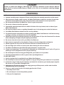
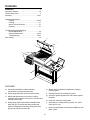
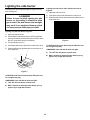
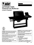
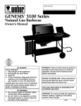
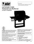
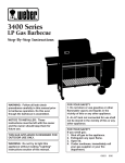
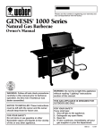
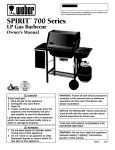
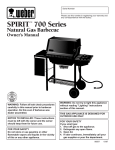
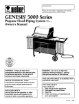
Serial Number Please use this number in registering your warranty and any correspondence with the factory. GENESIS 3500 LX ® Natural Gas Barbecue Owner’s Manual ® WARNING: Follow all leak check procedures carefully in this manual prior to barbecue operation. Do this even if barbecue was dealer assembled. NOTICE TO INSTALLER: These instructions must be left with the owner and the owner should keep them for future use. FOR YOUR SAFETY Do not store or use gasoline or other flammable vapors and liquids in the vicinity of this or any other appliance. WARNING: Do not try to light this appliance without reading "Lighting" instructions section of this manual. THIS GAS APPLIANCE IS DESIGNED FOR OUTDOOR USE ONLY. FOR YOUR SAFETY If you smell gas: 1. Shut off gas to the appliance. 2. Extinguish any open flame. 3. Open lid. 4. If odor continues, immediately call your gas supplier or your fire department. 98649 11/97 DANGER Failure to follow the Dangers, Warnings and Cautions contained in this Owner’s Manual may result in serious bodily injury or death, or in a fire or an explosion causing damage to property. WARNINGS Do not store a spare or disconnected LP tank under or near this barbecue. Improper assembly may be dangerous. Please carefully follow the assembly instructions in this manual. After a period of storage, and/or nonuse, the Weber Gas Barbecue should be checked for gas leaks and burner obstructions before using. See instructions in this manual for correct procedures. Do not operate the Weber Gas Barbecue if there is a gas leak present. Do not use a flame to check for gas leaks. Combustible materials should never be within 24 inches of the top, bottom, back or sides of your Weber Gas Barbecue. Do not put a barbecue cover or anything flammable on or in the storage area under the barbecue. Your Weber Gas Barbecue should never be used by children. You should exercise reasonable care when operating your Weber Gas Barbecue. It will be hot during cooking or cleaning, and should never be left unattended. Should the burners go out during operation, turn all gas valves off. Open the lid and wait five minutes before attempting to relight, using the lighting instructions. Do not use charcoal or lava rock in your Weber Gas Barbecue. Never lean over open grill or place hands or fingers on the front edge of the cooking box. Should a grease fire occur, turn off all burners and leave lid closed until fire is out. Do not enlarge valve orifices or burner ports when cleaning the valves or burners. The Weber Gas Barbecue should be thoroughly cleaned on a regular basis. LP gas is not natural gas. The conversion or attempted use of natural gas in an LP unit or LP gas in a natural gas unit is dangerous and will void your warranty. Do not attempt to disconnect any gas fitting while your barbecue is in operation. Use heat-resistant barbecue mitts or gloves when operating barbecue. LP GAS UNITS ONLY: Use the regulator that is supplied with your Weber Gas Barbecue. Do not attempt to disconnect the gas regulator or any gas fitting while your barbecue is in operation. A dented or rusty LP tank may be hazardous and should be checked by your liquid propane supplier. Do not use an LP tank with a damaged valve. Although your LP tank may appear to be empty, gas may still be present, and the tank should be transported and stored accordingly. If you see, smell or hear the hiss of escaping gas from the LP tank: 1. Get away from LP tank. 2. Do not attempt to correct the problem yourself. 3. Call your fire department. 2 WARRANTY Weber-Stephen Products Co. (Weber) hereby warrants to the ORIGINAL PURCHASER of this Weber Gas Barbecue that it will be free of defects in material and workmanship from the date of purchase as follows: Aluminum Castings, 10 years, Recycled Work Surfaces, 10 years, Cooking Grates and Flavorizer Bars, 3 years, All Remaining Parts, 5 years, when assembled and operated in accordance with the printed instructions accompanying it. Weber may require reasonable proof of your date of purchase. THEREFORE, YOU SHOULD RETAIN YOUR SALES SLIP OR INVOICE. This Limited Warranty shall be limited to the repair or replacement of parts which prove defective under normal use and service and which on examination shall indicate, to Weber's satisfaction, they are defective. Before returning any parts, contact Weber-Stephen Products Co. Customer Service Center. If Weber confirms the defect and approves the claim, Weber will elect to replace such parts without charge. If you are required to return defective parts, transportation charges must be prepaid. Weber will return parts to the purchaser, freight or postage prepaid. This Limited Warranty does not cover any failures or operating difficulties due to accident, abuse, misuse, alteration, misapplication, vandalism, improper installation or improper maintenance or service, or failure to perform normal and routine maintenance, including but not limited to damage caused by insects within the burner tubes, as set out in this owner's manual. Deterioration or damage due to severe weather conditions such as hail, hurricanes, earthquakes or tornadoes, discoloration due to exposure to chemicals either directly or in the atmosphere, is not covered by this Limited Warranty. There are no other express warrants except as set forth herein and any applicable implied warranties of merchantability and fitness are limited in duration to the period of coverage of this express written Limited Warranty. Some states do not allow limitation on how long an implied warranty lasts, so this limitation may not apply to you. Weber is not liable for any special, indirect or consequential damages. Some states do not allow the exclusion or limitation of incidental or consequential damages, so this limitation or exclusion may not apply to you. Weber does not authorize any person or company to assume for it any other obligation or liability in connection with the sale, installation, use, removal, return, or replacement of its equipment; and no such representations are binding on Weber. This Warranty applies only to products sold at retail. WEBER-STEPHEN PRODUCTS CO. Customer Service Center 250 South Hicks Road Palatine, IL 60067-6241 (800) 446-1071 3 PATENTS AND TRADEMARKS © 1997 Weber. Weber, , Genesis, Flavorizer and Crossover are registered U.S. trademarks; Perma-Mount, Gas Catcher, FlameCheck, Steam-N-Chips, Spider Stopper, and Warm-Up are U.S. trademarks of Weber-Stephen Products Co., 200 East Daniels Road, Palatine, IL 60067-6266. U.S.A. Genesis Gas Barbecues are covered under the following patent nos.: U.S.A. #4,677,964; 4,727,853; #4,777,927; #4,829,978; #4,860,724; #4,941,817; #4,966,125; #5,070,776; #D293,067; #D316,355; Canada: Rd 1987 Reg. #58,034; #1,279,540; #1,283,586; #1,300,994; #1,300,995. Printed in the U.S.A. 4 Contents WARNINGS ................................................................ 2 Warranty & Patents.................................................. 2-3 General Instructions.................................................... 6 Assembly ............................................................. 10-27 Operating Instructions Lighting........................................................ 28-30 Cooking ............................................................ 31 After a Period of Nonuse ................................. 31 Cleaning ........................................................... 31 Troubleshooting & Maintenance Annual Maintenance......................................... 32 General Maintenance.................................. 33-35 Troubleshooting ...........................................36-37 Parts Listing .............................................................. 39 b c e a d f g i h j a FEATURES: a) Convenient side table, condiment basket, wire accessory rack and warming rack. e) Weber Warm-Up Basket for additional cooking or warming space. b) Heavy gauge porcelain-on-steel lid seals in heat. f) c) Rapid read thermometer for precision cooking measures grill temperature, and can be removed and inserted into the food. g) Crossover Ignition System with Gas Catcher Ignition Chamber. d) Heavy gauge steel Flavorizer Bars distribute heat within the grill. Flavorizer Bars heat just the right amount of drippings for flavoring, letting excess fat drip past to help prevent flare-ups. i) Side burner for making sauces, gravies, etc., while main grill is in use. j) Sleek and sturdy base is an attractive addition to your patio or deck. Separate burners for temperature control. h) Catch pan catches excess grease. 5 General Instructions Your Weber Gas Barbecue is a stationary outdoor cooking appliance. With the Weber Gas Barbecue you can grill, barbecue, roast and bake with results that are difficult to duplicate with indoor kitchen appliances. The closed lid and Flavorizer Bars produce that "outdoor" flavor in the food. Storage The natural gas supply is easy to use and gives you more cooking control than charcoal fuel. Operating area ■ Not for use by children. ■ If there are local codes that apply to gas grills, you will have to conform to them. If there are no local codes, you must conform to the latest edition of the National Fuel Gas Code: ANSI Z 223.1. This Weber Gas Barbecue is designed for natural (piped in city) gas only. Do not use Liquid Propane (LP) bottled gas. The valves and orifices are for natural gas only. ■ Do not use with charcoal fuel. ■ Check that the area under the control panel and the bottom tray are free from debris that might obstruct the flow of combustion or ventilation air. The gas must be turned OFF at the natural gas supply when the Weber Gas Barbecue is not in use. WARNING: Only use this barbecue outdoors in a well ventilated area. Do not use in a garage, building, breezeway or any other enclosed area. These instructions will give you the minimum requirements for assembling your Weber Gas Barbecue. Please read the instructions carefully before using your Weber Gas Barbecue. Improper assembly can be dangerous. ■ ■ ■ ■ Never use your Weber Gas Barbecue under an unprotected combustible roof or overhang. ■ Your Weber Gas Barbecue is not intended to be installed in or on recreational vehicles and/or boats. ■ Do not use combustible materials within 24 inches of the top, bottom, back or sides of the grill. ■ The entire cooking box gets hot when in use. Do not leave unattended. ■ Keep any electrical supply cord away from any heated surface. ■ Keep the cooking area clear of flammable vapors and liquids, such as gasoline, alcohol, etc., and combustible materials. Gas supply testing 6 ■ Disconnect your Weber Gas Barbecue when the gas supply is being tested at high pressures. This appliance and its individual shutoff valve must be disconnected from the gas supply piping system during any pressure testing of that system at test pressures in excess of 1/2 psig (3.5 kPa). ■ Turn off your Weber Gas Barbecue when the gas supply is being tested at low pressures. This appliance must be isolated from the gas supply piping system by closing its individual manual shutoff valve during any pressure testing of the gas supply piping system at the pressure equal to or less than 1/2 psig (3.5 kPa). Notice Before Installation Contact your local municipality for any building codes regulating outdoor barbecue installations. In absence of local codes, you must conform to the latest edition of ANSI Z223.1. WE RECOMMEND THAT THIS INSTALLATION BE DONE BY A PROFESSIONAL. General Specifications for Piping Outside underground piping Outside underground piping may be copper tubing, type K or L (ASTM B88) or polyethylene plastic tube PE3306 (Minimum wall thickness .062") meeting ASTM 2513, latest specifications. American National Standards Institute (ANSI) Recommendations for gas supply installations: Steel pipe is not recommended for underground use unless it is protected with an approved coating, insulated from hose piping and cathodically protected. Connections: ■ ■ ■ ■ This barbecue is designed to operate at 7 inches of water column pressure (.2526 psi). It is recommended that copper tubing be corrosion protected with a satisfactory material such as TC Mastic. A manual shut-off valve must be installed outdoors, immediately ahead of any connections or change in pipe material. All buried fittings should be corrosion protected with a satisfactory material such as TC Mastic. An additional manual shut-off valve indoors should be installed in the branch fuel line in an accessible location near the supply line. Underground piping must have a minimum of 10" cover. Plastic tubing Plastic tubing is suitable only for outside underground use. The point of tie into the branch line should be carefully selected to avoid a drip leg or be downstream of a valve controlling another appliance. ■ Pipe compound should be used which is resistant to action of natural gas when connections are made. ■ The outdoor connector must be firmly attached to rigid, permanent construction. Gas line piping ■ ■ If the length of line required does not exceed 50 feet, use a 5/8" O.D. tube. One size larger should be used for lengths greater than 50 feet. ■ The transition from metallic pipe to plastic pipe should be made outside and at least 10" underground. ■ When compression or crimp type mechanical joints are used with plastic pipe, it is advisable to use an internal rigid stiffener in conjunction with the fitting. ■ The stiffener should be assembled flush with the end of the tube and extend at least to the outside edge of the compression fitting. Testing connections You will need a soap and water solution and a rag or brush to apply it. Indoor and above ground piping can be steel or copper. All connections and joints must be thoroughly tested for leaks after gas has been turned into the line. Steel DANGER New standard weight (Schedule 40) steel pipe with malleable iron fittings. Do not use an open flame to check for gas leaks. Be sure there are no sparks or open flames in the area while you check for gas leaks. This will result in a fire or explosion which can cause serious bodily injury or death, and damage to property. Copper New copper tubing type K or L. Copper tubing must meet requirements of ASTM B88 latest edition. Use flared fittings. Metallic ball sleeve compression fittings must not be used. Wet the fitting with a soap and water solution. Any bubbles that form or grow indicate a leak. If bubbles occur shut off gas, tighten the fitting, and retest. Copper tube joints may be soldered or brazed with material having a melting point in excess of 1,000°F. WARNING: If a leak persists after tightening the fitting, turn gas off at the supply. DO NOT OPERATE YOUR BARBECUE. Contact Weber-Stephen Customer Service. 7 Typical natural gas supply installation to a concrete patio or pad Typical natural gas supply installation over an existing post View from behind barbecue View from behind barbecue Outside Outside Accessible Locking Shut off Accessible Locking Shut off Inside Indoor Shut off Inside Gas Supply Indoor Shut off Gas Supply Figure 1 Figure 3 CAUTION: Follow "General Specifications for Piping" in this manual. WARNING: Turn off the natural gas supply at the source before working on the post. We recommend that this installation be done by a professional. Prepare the post so that it will be approximately 2 inches above the pad or ground. Inspect the gas supply line at the post for any sign of deterioration or corrosion. CAUTION: Combustible materials should never be within 24 inches of the top, bottom, back or sides of the barbecue. Do not locate under overhead combustible construction. CAUTION: If you are in doubt as to the condition of an existing natural gas supply line, you should contact a professional or your local gas utility before attempting any assembly. Typical natural gas supply installation to a wood deck View from behind barbecue CAUTION: Combustible materials should never be within 24 inches of the top, bottom, back or sides of the barbecue. Do not locate under overhead combustible construction. Outside Accessible Locking Shut off Inside Indoor Shut off Gas Supply Figure 2 CAUTION: Follow "General Specifications for Piping" in this manual. We recommend that this installation be done by a professional. CAUTION: Combustible materials should never be within 24 inches of the top, bottom, back or sides of the barbecue. Do not locate under overhead combustible construction. 8 Recommended concrete pad requirements We recommend a pad a minimum of 40 inches left to right, 20 inches front to back and 4 inches deep (1.85 cubic feet). Figure 4. Note - Cubic feet is determined by multiplying length times width times depth and dividing by 1728. 20” 40” 4” Figure 4 If you use a concrete bag mix, use the mix for maximum strength. An average 80 pound bag of concrete mix will make approximately 2/3 of a cubic foot of concrete. Note - Follow the concrete bag mix, manufacturers recommendations concerning pad preparation, gravel, sand, etc. Figure 5. Concrete Pad Crushed stone, sand or gravel Earth Figure 5 CAUTION: Allow fresh concrete to cure completely before attempting to anchor the barbecue to the concrete. 9 Step 1 Assembly Check package contents Tools needed Regular screwdriver Cooking box (assembly) Phillips screwdriver Hammer One 7/16 inch or an adjustable wrench Lid (assembly) Pliers ® ® Tape Measure Bottom tray Pencil Electric drill Control panel Supplies needed You will need a soap and water solution to check for gas leaks. (See Step "Check for gas leaks.") Work table Note - The hardware size of nuts, bolts, and screws is given. For example "1/4-20 x 2 inch bolt" means a bolt 1/4 inch in diameter with 20 threads to the inch, 2 inches long. On a small screw for example, "6-32 x 1/2 inch screw" means a number 6 screw, with 32 threads to the inch, 1/2 inch long. Spacer bracket While we give much attention to our products, unfortunately an occasional error may occur. If a part is missing, do not go back to the store. Call the Weber Customer Service Center toll free 1-800-446-1071 to receive immediate assistance. Have your owner’s manual and serial number of the barbecue available for reference. Gas supply line (with the flare fitting loosely attached for shipping purposes) 10 Left frame Front Panel Cooking grate (2) Right frame Catch pan holder Side frame (2) Catch Pan Accessory rack Drip pans (2) Warm-Up Basket Thermometer Warming Rack Condiment basket Five long Flavorizer Bars Side burner assembly Eight short Flavorizer Bars Burner grate Side panel (2) Side burner knob Base panel Side burner locks (2) Note: The locks are taped to the inside of the side burner lid. 11 Check contents of hardware packs Ten plastic buttons Three burner control knobs End bracket Three tool holders Three tubing plugs Two Phillips screws/washers Manifold bracket Two hinge pins (hardware size: 1/4 x 1 1/2 inch clevis pin) (actual size) One 1/4-20 x 2 inch bolts (actual size) Six 1/4-20 x 1/2 inch bolts (actual size) One 1/4-20 keps nut Seven nylon washers (actual size) Two hair pin cotters (actual size) 12 Step 2 Step 3 Assemble frame Continue frame assembly You will need: left frame, right frame, two nylon washers, two 1/4-20 x 1/2 inch bolts and a 7/16 inch wrench. You will need: frame assembly, two side frames, four 1/4-20 x 1/2 inch bolts, four nylon washers and a 7/16 inch wrench. Note - Work on carpeted area (on grass, or on one of the boxes) to protect the finish during frame assembly. Assemble one side frame onto the leg tabs of the right frame, and the second side frame onto the leg tabs of the left frame. Make sure the anchoring base plates are facing in toward each other. The tabs must be on the inside of the frames when the joints are closed. Put the frame pieces so the leg tabs are up. Put the right frame to your right and left frame to your left. Figure 1. Slip the two frame halves together with the tabs inside, until the tabs of the right frame are inside the left frame and the holes align. Figure 1 (a). Add front panel with the large hole down and to your right. Add washers, then bolts. Do not fully tighten these bolts. You will tighten them once the base is anchored. Figure 2 (a). Slip washers over bolts; insert and tighten bolts. (If you try to insert a bolt and there are no holes, you have the left frame turned the wrong way. Turn the left frame around.) Figure 1 (b). Turn frame assembly right side up. (a) Anchoring base plates are facing in (a) Do not fully tighten these bolts Figure 2 (b) Figure 1 13 Step 4 Step 5 Install side burner locks Measure and drill holes Note: The locks are taped to the inside of the side burner lid. You will need: Completed frame assembly, base panel, tape measure, and pencil. You will need: frame assembly, two side burner locks and a 7/16 inch wrench. CAUTION: Combustible materials should never be within 24 inches of the top, bottom, back or sides of the barbecue. Do not locate under overhead combustible construction. Turn frame assembly right side up. Loosen the right rear 1/4 x 20 bolt. Install the side burner lock. The “U” shape cut out of the lock slips down over the bolt. Tighten with a wrench. Figure 3 (a). Note - With the lid open the depth of the barbecue is 28 inches, front to back. Loosen the right front 1/4 x 20 bolt. The side burner lock fits between the front panel and the frame. The “U” shape cut out slips up over the bolt. Tighten with a wrench. Figure 3 (b). Set the completed frame assembly in position on your deck, concrete pad, or patio for anchoring. Measure the distance from the outside of the base plate to the outside of the other base plate. It should be 37 1/4” across. Figure 4. (a) Note: If the measurement is not 37 1/4” across adjust the legs as necessary so that the measurement is 37 1/4”. 37 1 /4 Figure 4 (b) Place the base panel in between the legs to insure fit. Figure 5. Once the fit is established, remove the base panel and mark the holes. CAUTION: A minimum of 2 bolts are required on each side. You are now ready to anchor the base. Figure 3 Figure 5 14 Step 6 Typical installation of the base for an existing concrete patio, new pad or wood deck (continued) Typical installation of the base for an existing concrete patio, new pad or wood deck Method 1 - Concrete CAUTION: Combustible materials should never be within 24 inches of the top, bottom, back or sides of the barbecue. Do not locate under overhead combustible construction. A strike anchor, a minimum size of 3/8 inch x 3 1/2 inches long with a 3/8 inch flat washer and 3/8 inch nut. Figure 7. Note - Use a 3/8 inch diameter concrete drill bit for drilling the hole for the strike anchor. Note - With the lid open the depth of the barbecue is 28 inches, front to back. Strike anchor For anchoring, we recommend use of one of the following methods: 3/8 inch nut WARNING: Whichever method used, the base must be bolted down (anchored) at a minimum of four anchoring points (two per side) prior to barbecue assembly. One anchor in each corner of the base plate. Figure 6. 3/8 inch flat washer Mount plate Drilled hole Figure 7 1 4 2 3 Figure 6 15 Method 2 - Concrete Typical installation of the base for an existing concrete patio, new pad or wood deck (continued) A concrete lag bolt, a minimum of 3/8 inch x 2 1/2 inches long with a 3/8 inch diameter long lag shield and a 3/8 inch flat washer. Figure 8. Method 4 - Wood deck After assembling the base according to the assembly instructions, position the base assembly on your deck for anchoring. Note - Use a 5/8 inch concrete drill bit for drilling the hole for the lag shield. CAUTION: Combustible materials should never be within 24 inches of the top, bottom, back or sides of the barbecue. Do not locate under overhead combustible construction. Concrete lag bolt 3/8 inch flat washer CAUTION: For a deck installation, it is recommended to anchor one screw into a joist. Mount plate Note - With the lid open, the depth of the barbecue is 28 inches, front to back. Lag shield Anchor the base to the deck. We recommend using a minimum of a 3/8 inch x 1 1/2 inch lag bolt with a 3/8 inch flat washer. Figure 10. Note - Use a 3/16 inch drill bit for drilling a pilot hole for a 3/8 inch lag bolt. Drilled hole 3/8 inch x 1 1/2 inch lag bolt Figure 8 Method 3 - Concrete 3/8 inch flat washer A 3/8 inch machine screw anchor, using a 3/8-16 x 1 1/2 inch machine screw and a flat washer. Figure 9. Note - Use a 3/4 inch diameter concrete drill bit for drilling the hole for the screw base. The machine screw anchor requires a setting tool. Mount plate Drilled hole 3/8-16 x 1 1/2 machine screw Figure 10 3/8 inch flat washer WARNING: Whichever method used, the base must be bolted down (anchored) at a minimum of four anchoring points (two per side) prior to barbecue assembly. One anchor in each corner of the base plate. Figure 11. Mount plate 3/8 inch screw anchor Drilled hole Figure 9 1 4 2 3 Figure 11 16 Step 7 Step 8 Tighten all frame bolts Add cooking box Fully tighten the 1/4-20 bolts in the frame assembly, that you only started in Step “Continue Frame Assembly” Figure 12. You will need: cooking box assembly, spacer bracket, 1/4-20 x 2 inch bolt, nylon washer, 1/4-20 keps nut, pliers and a 7/16 inch wrench. Set the cooking box in the frame so the burner tubes are under the frame brace. Figure 13. Note: Be careful when sliding the burner tubes through the side frame. Burner tubes Frame brace Figure 12 Figure 13 17 Your Weber Gas Barbecue burner assembly has been factory assembled, pressure and flame tested. As a safety precaution we recommend you check the burner alignment: Slide the cooking box to the left within the frame. Put the washer on the bolt. Take the spacer bracket and hold it up to the frame making sure both tabs fit underneath the frame cross piece. Figure 14 (a). Insert the bolt through the center hole in the spacer bracket, frame and cooking box with the head of the bolt outside the spacer bracket. Figure 14 (b). Add keps nut. Tighten by holding the bolt with pliers while you tighten the nut with the 7/16 inch wrench. Spacer bracket a) Are the ends of the burners under the washers at the left rear and left front of the cooking box? The screws are only guides. Do not tighten. Figure 15 (a). b) Are the wing nuts under the burner assembly hand tight? Do not tighten with pliers. Figure 15 (b). Frame cross piece (a) If you answered YES to a and b, the burners are correctly aligned. If you answered NO, the burners are misaligned. Contact Weber-Stephen Customer Service. Do not use barbecue. Guide screw (a) (b) Tab Keps nut View from behind cooking box Bolt Nylon washer (b) Figure 15 Wing nuts Figure 14 18 Step 9 Step 10 Install igniter Connect barbecue gas supply line to the natural gas supply Note - The igniter wires are already attached to the Gas Catcher Ignition Chamber and the igniter. This was done to factory test the ignition system. Note - We recommend that the connection between the barbecue gas supply line and the natural gas supply be flare to flare. A 3/8-inch flare fitting has been included with the barbecue gas supply line of your gas barbecue. The fitting is loosely connected for shipping and should be removed before installation. The igniter lock nut is on the igniter. Insert the top of the igniter up through the large part of the keyhole in the frame brace. Figure 16 (b). Loosen the igniter lock nut and slide the igniter into the small part of the keyhole. Figure 16 (c). Tighten the igniter lock nut. Figure 16. You will need: barbecue gas supply line, 3/8 inch flare fitting, 3/4 inch and 11/16 inch wrenches. WARNING: This barbecue is NOT portable. It must be bolted down at all times when it is connected to a natural gas supply. Note - If the igniter works loose, carefully tighten the igniter lock nut with an adjustable wrench or pliers. (a) Unscrew the 3/8 inch flare fitting from the barbecue gas supply line. Apply pipe sealant to the threads of the pipe fitting. Screw the pipe fitting end of the 3/8 inch flare fitting into the natural gas supply pipe. Tighten with an 11/16 inch wrench. Figure 17 (a). Attach the flare nut on the barbecue gas supply line to the flare fitting end of the 3/8 inch flare fitting. Tighten with a 3/4 inch wrench. Figure 17 (a). (b) Attach the flare nut at the other end of the barbecue gas supply line to the manifold fitting. Tighten with a 3/4 inch wrench. Figure 17 (b). Frame brace (b) Figure 16 (c) Keyhole in frame brace Igniter lock nut Frame brace Figure 17 Apply pipe sealant here Small part of keyhole in frame brace (a) Natural Gas Supply Pipe Pipe fitting end of 3/8-inch Flare Fitting Flare fitting end of 3/8-inch Flare Fitting 19 Barbecue gas supply line Step 11 Step 12 Check all valves are off Install side burner You will need: one burner control knob. You will need: side burner assembly, burner grate, and manifold bracket. (Valves are shipped in the OFF position, but you should check to be sure.) Put the knob on each valve. Check by pushing down and turning clockwise. If they do not turn they are off. Proceed to the next step. Figure 18. WARNING: Make sure gas supply is OFF. Slide the side burner assembly into the open end of the right frame. Route the side burner hose around the tank panel so it will not interfere with scale indicator rod. The side burner hose is connected in the following manner: Slide back the collar of the quick disconnect on the manifold. Push the male fitting of the side burner hose into the quick disconnect, and maintain pressure. Slide the collar closed. Figure 19a. Figure 19b shows the quick disconnect engaged.Install burner grate. Check to be sure the side burner valve is OFF. Push side burner control knob down and turn clockwise. Figure 19. Figure 18 Figure 19 Male fitting a) Manifold side view Quick disconnect engaged b) Side burner hose 20 Manifold side view Step 13 Step 14 Install manifold bracket Purge air from gas lines You will need: manifold bracket. You will need: one burner control knob. Hook the bracket onto the manifold at the center burner valve. Figure 20. Place your hand underneath the bracket. Lift the bracket, manifold and cooking box slightly as a unit and hook onto the frame brace. Figure 21 (a). DANGER Be sure there are no sparks or open flames in the area while purging. This can cause fire, explosion or serious bodily injury. Frame brace Manifold bracket It is necessary to bleed the air out of newly installed gas lines. Turn gas supply ON at the source. Put on the front burner control knob. Push the front burner control knob down and turn to HI. When you start to smell gas, turn front burner control knob to OFF. Figure 21. (a) Figure 20 View from below cooking box Figure 21 21 Step 15 Check: Check for gas leaks a) Gas supply line to manifold connection. Figure 24 (a). b) Manifold to side burner hose connection. Figure 24 (b). DANGER WARNING: If there is a leak at connection (a) or (b), retighten the fitting with a wrench and recheck for leaks with soap and water solution. Do not use an open flame to check for gas leaks. Be sure there are no sparks or open flames in the area while you check for leaks. This will result in a fire or explosion which can cause serious bodily injury or death and damage to property. If a leak persists after retightening the fitting, turn OFF the gas. DO NOT OPERATE THE BARBECUE. Contact your dealer. c) Side burner hose to side burner connection. Figure 24 (c). WARNING: You should check for gas leaks every time you disconnect and reconnect a gas fitting. d) Valves to manifold connections. Figure 24 (d). WARNING: If there is a leak at connections (c) or (d), turn OFF the gas. DO NOT OPERATE THE BARBECUE. Contact your dealer. Note - All factory made connections have been thoroughly checked for gas leaks. The burners have been flame tested. As a safety precaution you should recheck all fittings for leaks before using your Weber Gas Barbecue. Shipping and handling may have loosened or damaged a gas fitting. e) Barbecue gas supply line to natural gas supply connection. Figure 24 (e). WARNING: Perform these leak checks even if your barbecue was dealer or store assembled. WARNING: If there is a leak at connection (e), turn OFF the gas. DO NOT OPERATE THE BARBECUE. Contact your installer. You will need: soap and water solution and a rag or brush to apply it. When leak checks are complete, turn gas supply OFF and rinse connections with water. Make sure side burner is OFF. Remove valve control knob and screws. Remove porcelain top. Figure 22. f) Reinstall the side burner cover. Figure 22. (a) (b) Figure 22 To perform leak checks: Turn ON gas supply at the source. Figure 23. Gas supply shut off at the house (c) Figure 23 WARNING: Do not ignite burners while leak checking. (e) Check for leaks by wetting the connections with the soap and water solution and watching for bubbles. If bubbles form or if a bubble grows there is a leak. (d) Note - Since some leak test solutions, including soap and water, may be slightly corrosive, all connections should be rinsed with water after checking for leaks. Figure 24 22 Step 16 Step 17 Add base panel Install side panels You will need: Base panel. You will need: two side panels, and eight plastic buttons. Put the right side in and down, tilt and set the left side in place. Figure 25. From the inside of the frame assembly, set the left side panel in place between the side frame legs. Notice that there are two sets of holes in each side panel. Align the holes in the side panel to match the holes in the left side frame legs. Push in the four plastic buttons. Figure 26 (a). Repeat with the right side panel. top Left side panel Base panel Figure 25 Right side panel bottom (a) Figure 26 23 Step 18 Step 19 Install Flavorizer Bars and Cooking Grates Install the bottom tray You will need: five long Flavorizer Bars, eight short Flavorizer Bars and two cooking grates. You will need: bottom tray, catch pan holder, catch pan and one drip pan. Set the long Flavorizer Bars side to side in the lower position, then set the short Flavorizer Bars front to back in the upper position in the cooking box. Figure 27. Finger grip on front edge of bottom tray Front side of catch pan holder Figure 29 Hook the ends of the catch pan holder into the hole in the bottom tray. Figure 30. The front of the catch pan holder must be on the same side as the finger grip of the bottom tray. Figure 27 The open "U" of the cooking grates goes down. Set the cooking grates onto the ledges in the cooking box. Figure 28. Finger grip Figure 30 Slide the bottom tray onto the mounting rails under the cooking box with finger grip toward you. Figure 31. CAUTION: Do not line bottom tray with aluminum foil. It can cause grease fires by trapping the grease and not allowing grease to flow into the catch pan. Figure 28 Bottom tray Figure 31 Put the foil drip pan into the catch pan. Slide the catch pan into the catch pan holder with its finger grip towards you. 24 Step 20 Step 21 Install Lid You will need: lid, two hinge pins and two hair pin cotters. Add tool holders, control panel and burner control knobs Set the lid in place. Align the hinges at the rear of the barbecue. Insert hinge pins from the outside. Insert hair pin cotters into the small holes in the hinge pins. Figure 32. You will need: three tool holders, control panel, two Phillips screws/washers, a Phillips screwdriver, and three burner control knobs. Hook the tool holders over the frame rail and snap down into place. Figure 33. Hair pin cotter Set the control panel in place over both frame braces. (Hold the Crossover Ignition button up while setting the control panel in place.) Line up the holes in the control panel with the holes in the inserts in the frame brace. Insert screws and tighten with a Phillips screwdriver until snug. Do not overtighten. Figure 33 (a). Hinge pin Push on the burner control knobs. Figure 33 (b). Insert in frame brace Crossover Ignition Button (a) Figure 32 Control panel Phillips screws/ washers Tool holders Figure 33 25 (b) Step 22 Step 23 Secure side burner Install the condiment basket Stand to the right side of the barbecue. Slightly pull back both side burner locks. Slide the side burner toward the control panel. The locks will snap into the slots in the front and back of the side burner. Figure 34. You will need: condiment basket and end bracket. Insert one wire end of the condiment basket into the hole in the side frame. Figure 35 (a). Insert the opposite wire end of the condiment basket into the hole in the end bracket. Hold the end bracket at an angle so the lower tab is inside the frame tube. Push the bracket into the frame. Figure 35 (b). Check to see that the lower tab of the bracket is hooked in the slot in the frame. Figure 35 (c). CAUTION: Make sure both locks have snapped into place. To fully seat the bracket, you may have to tap it lightly with a hammer. WARNING: If the end bracket is in any way cracked or damaged, do not use the condiment basket. Call our Customer Service Center to order a new part. Wire end (a) View from top (b) View from rear of barbecue Figure 34 Slot in frame (view from below) (c) Figure 35 26 Step 24 Step 25 Install the accessory rack Complete accessory installation You will need: accessory rack. You will need: Warm-Up Basket, warming rack, work table, three tubing plugs, thermometer and a hammer. Rest the left end of the accessory rack on the base panel. Figure 36 (a). Insert the right hooks into the right side frame slots. Figure 36 (b). Insert one end of the Weber Warm-Up Basket into the hole in the right end of the lid and the other end into the slot in the left end of the lid. Figure 37 (a). Raise the left end up and slide left hooks into the left side frame slots. Figure 36. Set the warming rack into the slots at the rear of the cooking box. Figure 37 (b). Set the work table onto the left side rails. Figure 37 (c). Insert the thermometer into its holder. Figure 37 (d). Insert the tubing plugs into the ends of the frame. To fully seat the plugs, you may have to tap them lightly with a hammer. Figure 37 (e). Left side frame slots (a) (a) (d) (b) (b) (c) Left hooks (e) Figure 36 Right side frame Figure 37 27 OPERATING INSTRUCTIONS Lighting 1) Open the lid. Figure 1. Summary lighting instructions are on the control panel. 2) Make sure all burner control knobs are turned OFF. (Push each burner control knob down and turn clockwise.) DANGER 3) Turn gas supply valve on. Failure to open lid while igniting the barbecue, or not waiting 5 minutes to allow the gas to clear if the barbecue does not light, may result in an explosive flame-up which can cause serious bodily injury or death. WARNING: Do not lean over open barbecue. Keep your face and body at least one foot away from the matchlight hole when lighting the barbecue. 4) Push Front burner control knob down and turn to START/ HI. 5) Push the Crossover Ignition Button several times, so it clicks each time. Crossover Ignition System 6) Check that the burner is lit by looking through the matchlight hole on the front of the cooking box. Note - The Crossover Ignition System ignites the Front burner with a spark from the igniter electrode inside the Gas Catcher Ignition Chamber. You generate the energy for the spark by pushing the Crossover Ignition Button until it clicks. WARNING: If the burner does not light, turn the Front burner control knob to OFF and wait 5 minutes to let the gas clear before you try again or try to light with a match. WARNING: Check gas supply line before each use of barbecue for nicks or cracking. If the gas supply line is found to be damaged in any way, do not use the barbecue. Replace using only Weber authorized replacement gas supply line. Order from WeberStephen Products Co., Customer Service Center. 7) After the FRONT burner is lit you can turn on the other burners. Note - Always light the FRONT burner first. The other burners ignite from the FRONT burner. Crossover Ignition System To Extinguish 1 Turn gas supply OFF at the source, then push down and turn each burner control knob clockwise to OFF. 7 7 5 2 6 4 Figure 1 28 Manual Lighting WARNING: Do not lean over open barbecue. Keep your face and body at least one foot away from the matchlight hole when lighting the barbecue. DANGER Failure to open lid while igniting the barbecue, or not waiting 5 minutes to allow the gas to clear if the barbecue does not light, may result in an explosive flame-up which can cause serious bodily injury or death. 5) Push Front burner control knob down and turn to START/ HI. 6) Check that the burner is lit by looking through the matchlight hole on the front of the cooking box. WARNING: If the burner does not light, turn the Front burner control knob to OFF and wait 5 minutes to let the gas clear before you try again or try to light with a match. 1) Open the lid. Figure 2. 2) Make sure all burner control knobs are turned OFF. (Push each burner control knob down and turn clockwise.) 7) After the FRONT burner is lit you can turn on the other burners. Note - Always light the FRONT burner first. The other burners ignite from the FRONT burner. 3) Turn gas supply valve on. 4) Strike a match and put the flame into the matchlight hole in the front of the cooking box. To Extinguish Manual Lighting 1 Turn gas supply OFF at the source, then push down and turn each burner control knob clockwise to OFF. 7 7 2 4, 6 5 Figure 2 29 Lighting the side burner Lighting the side burner if the main burners are lit. Figure 4. The side burner has a separate ignition system from the main cooking box. DANGER 1) Open the side burner lid. 2) Push down and turn the side burner control to HI. 3) Press the side burner igniter button several times so it clicks each time. Failure to open lid while igniting the side burner, or not waiting 5 minutes to allow gas to clear if the side burner does not light, may result in an explosive flame-up which can cause serious bodily injury or death. 1 2 Lighting only the side burner. Figure 3. 1) Open the side burner lid. 2) Check that the side burner valve is OFF (push down and turn clockwise), and all main burner control valves are OFF (push down and turn clockwise). 3 Figure 4 3) Turn gas supply valve on. CAUTION: Side burner flame may be difficult to see on a bright sunny day. 4) Push down and turn the side burner control valve to HI. 5) Push the side burner igniter button several times so it clicks each time. WARNING: If the side burner does not light: 1 a) 4 b) Wait 5 minutes to let the gas clear before you try again or try to light with a match. 2 5 Figure 3 CAUTION: Side burner flame may be difficult to see on a bright sunny day. WARNING: If the side burner does not light: a) Turn OFF the side burner control valve. Turn OFF the side burner control valve. b) Wait 5 minutes to let the gas clear before you try again or try to light with a match. 30 Cooking After a Period of Nonuse You can adjust the FRONT, CENTER and BACK burners as desired. The control settings High (H), Medium (M), Low (L), or Off (O) are described in your Weber cookbook. The cookbook uses these notations to describe the settings of the FRONT, CENTER, and BACK burners. For example, to sear steaks you would use (HHH) (all burners at high). Then to complete cooking you would use (MOM) (FRONT at medium, CENTER off, and BACK at medium). See your Weber cookbook for detailed cooking instructions. ■ The Weber Gas Barbecue should be checked for gas leaks and any obstructions in the burner tubes before using. (See Sections General and Annual Maintenance.) ■ Check that the areas under the control panel and the bottom tray are free from debris that might obstruct the flow of combustion or ventilation air. ■ The Spider Stopper Guards should also be checked for any obstructions. (See Section "Annual Maintenance.") Note: The temperatures inside your cooking box, for the first few uses, while surfaces are still very reflective, may be hotter than those shown in your cookbook. Cooking conditions may require the adjustment of the burner controls to attain the correct cooking temperatures. Periodic Cleaning CAUTION: Replace thermometer in lid when not in use. Do not leave thermometer in food while cooking. WARNING: Turn your Weber Gas Barbecue OFF and wait for it to cool before cleaning. If burners go out during cooking, open lid, turn off all burners and wait 5 minutes before relighting. CAUTION: Do not clean your Flavorizer Bars or cooking grates in a self-cleaning oven. Replacement cooking grates and Flavorizer Bars are available through your retailer or the Weber-Stephen Customer Service Center. Preheating Your Weber Gas Barbecue is an energy efficient appliance. It operates at a low B.T.U. rate for economy. To preheat, after lighting, close lid and turn all burners to high (HHH). Preheating to between 500° and 550° F (260° and 290° C) will take 10 to 15 minutes depending on conditions such as air temperature and wind. Outside surfaces - Use a warm soapy water solution. CAUTION: Do not use oven cleaner, abrasive cleansers (kitchen cleansers) cleaners that contain citrus products or abrasive cleaning pads on barbecue or cart surfaces. Drippings and grease The Flavorizer Bars are designed to "smoke" the right amount of drippings for flavorful cooking. Excess drippings and grease accumulate in the catch pan under the bottom tray. Disposable foil liners are available that fit the catch pan. Bottom tray - Remove excess grease and then wash with warm soapy water. Flavorizer Bars and Cooking Grates - Clean with a suitable brass bristle brush. As needed, remove from grill and wash with warm soapy water. WARNING: Check the bottom tray for grease buildup before each use. Remove excess grease to avoid a grease fire in the bottom tray. Catch pan - Disposable foil trays are available, or you can line the catch pan with aluminum foil. To clean the catch pan, wash with warm soapy water. Thermometer - Wipe with warm soapy water, clean with plastic scrub ball. Do not put in dishwasher or submerge in water. Inside cooking box - Brush any debris off of burners tubes. DO NOT ENLARGE BURNER PORTS (OPENINGS). Wash inside of cooking box with warm soapy water. Inside Lid - While lid is warm, wipe inside with paper towel to prevent flaking due to grease build-up. 31 If a leak persists after retightening the fitting, turn OFF the gas. DO NOT OPERATE THE BARBECUE. Contact your dealer. Annual Maintenance After a period of nonuse we recommend that you perform the following maintenance procedures for your safety. c) Side burner hose to side burner connection. Figure 5 (c). WARNING: Check gas supply line before each use of barbecue for nicks or cracking. If the gas supply line is found to be damaged in any way, do not use the barbecue. Replace using only Weber authorized replacement gas supply line. Order from WeberStephen Products Co., Customer Service Center. WARNING: If there is a leak at connections (c) or (d), turn OFF the gas. DO NOT OPERATE THE BARBECUE. Contact your dealer. d) Valves to manifold connections. Figure 5 (d). e) Barbecue gas supply line to natural gas supply connection. Figure 5 (e). WARNING: If there is a leak at connection (e), turn OFF the gas. DO NOT OPERATE THE BARBECUE. Contact your installer. CAUTION: If the barbecue gas supply line is damaged in any way or leaking, do not use the barbecue. ■ Inspect the burners for correct flame pattern. Clean if necessary, following the procedures outlined in the "General Maintenance" section of this manual. ■ Check all gas fittings for leaks. When leak checks are complete, see steps “Add side panels” and “Add base panel” to reinstall. Turn gas supply OFF at the source and rinse connections with water. (a) DANGER Do not use an open flame to check for gas leaks. Be sure there are no sparks or open flames in the area while you check for leaks. This will result in a fire or explosion which can cause serious bodily injury or death, and damage to property. (b) WARNING: You should check for gas leaks every time you disconnect and reconnect a gas fitting. (c) You will need: a soap and water solution and a rag or brush to apply it. To perform leak checks: Make sure all burners are in the OFF position. Turn on gas supply. Refer to the steps “Add side panels” and “Add base panel” to remove the panels to expose the gas supply line for leak checking. (d) (e) WARNING: Do not ignite burners while leak checking. Check for leaks by wetting the connections with the soap and water solution and watching for bubbles. If bubbles form or if a bubble grows there is a leak. Note - Since some leak test solutions, including soap and water, may be slightly corrosive, all connections should be rinsed with water after checking for leaks. Figure 5 Inspection and Cleaning of the Weber Spider Stopper Guards Check: a) Gas supply line to manifold connection. Figure 5 (a). To inspect the Spider Stopper Guards, remove the control panel and look to see if they have dust or dirt on their outside surfaces. If they are dirty, brush off the outside surface of the Spider Stopper Guards with a soft bristle brush (an old toothbrush for example). Check that there are no gaps in the Spider Stopper Guards’ seams or in the fit around the burners or valves. (See Section "General Maintenance".) b) Manifold to side burner hose connection. Figure 5 (b). WARNING: If there is a leak at connection (a) or (b), retighten the fitting with a wrench and recheck for leaks with soap and water solution. 32 General Maintenance Main Burner Flame Pattern Weber Spider Stopper Guards The Weber Gas Barbecue burners have been factory set for the correct air and gas mixture. The correct flame pattern is shown in Figure 8. Your Weber Gas Barbecue, as well as any outdoor gas appliance, is a target for spiders and other insects. They can nest in the venturi section of the burner tubes. This blocks the normal gas flow, and can cause the gas to flow back out of the air shutter. Figure 6. This could result in a fire in and around the air shutters, under the control panel, causing serious damage to your barbecue. Tips occasionally yellowish Burner inside cooking box Light blue Venturi Dark blue Flames Figure 8 Venturi fin Air shutter If the flames do not appear to be uniform the length of the burner tube, follow the burner cleaning procedures. Figure 6 The Weber Spider Stopper Guard is factory installed. It fits tightly around the air shutter section of the burner tube and the valve, thereby preventing spiders and other insects access to the burner tubes through the air shutter openings. Figure 7. Main Burner Cleaning Procedure Turn off the gas supply. Remove the manifold. (See Section “Replacing the main burners”.) Look inside each burner with a flashlight. Figure 9. Weber Spider Stopper Guard Figure 9 Clean the inside of the burners with a wire (a straightened out coat hanger will work). Figure 10. Check and clean the air shutter opening at the ends of the burners. Check and clean the valve orifices at the base of the valves. Use a brass bristle brush to clean outside of burners. This is to make sure all the burner ports are fully open. Figure 7 We recommend that you inspect the Weber Spider Stopper Guards at least once a year. (See section “Annual Maintenance”.) Also inspect and clean the Spider Stopper Guards if any of the following symptoms should ever occur. 1. The smell of gas in conjunction with the burner flames appearing yellow and lazy. 2. Barbecue does not reach temperature. Figure 10 3. Barbecue heats unevenly. CAUTION: Do not enlarge the burner ports when cleaning. 4. One or more of the burners do not ignite. DANGER Failure to correct these symptoms may result in a fire which can cause serious bodily injury or death and cause damage to property. Replacing Main Burners a) Your Weber Gas Barbecue must be OFF and cool. b) Turn gas OFF at source. c) Remove control panel: take off the burner control knobs. Remove the screws holding the control panel in place. Lift off the control panel. 33 d) Unlatch the Spider Stopper Guards and remove. Figure 11. h) Lift and twist the burner assembly slightly, to separate the crossover tube from the burners. Figure 14. Remove the burners from the cooking box. Crossover tube Figure 14 Figure 11 e) Disconnect gas supply line and side burner. i) f) CAUTION: The burner openings must be positioned properly over the valve orifices. Figure 15 (a). Remove the manifold bracket and unscrew the two wing nuts that hold the manifold to the cooking box. Pull the manifold and valve assembly out of the burners and carefully set it down. Figure 12. To reinstall the burners, reverse steps c) through g). Check proper assembly before fastening manifold in place. Figure 15 (b). View from behind cooking box Burner opening (a) Valve orifice Wing nuts Figure 12 g) Slide the burner assembly out from under the guide screw and washer in the corners of the cooking box. Figure 13. (b) Guide screw Figure 15 Figure 13 34 j) Crossover Ignition System Operations Reinstall the Spider Stopper Guards. Slightly rotate the Spider Stopper Guards so that the seams are in line with the Venturi fins. There should be no gaps in the seams or in the fit around the burners and valves. Figure 16. If the Crossover Ignition System fails to ignite the Front burner, light the Front burner with a match. If the Front burner lights with a match, then check the Crossover Ignition System. ■ Check that both the white and black ignition wires are attached properly. Figure 17. Check fit around valve Venturi fin White wire Black wire Check fit around burner Figure 16 Figure 17 CAUTION: If the Spider Stopper Guards do not fit tightly, contact Weber-Stephen Customer Service. ■ Check that the Crossover Ignition button pushes the igniter (button) down, and returns to the up position. ■ Check to see if the igniter is loose in the frame. Tighten if necessary; see Step “Install igniter” for correct procedure. k) Reconnect gas supply line. See “Check for gas leaks”. If the Crossover Ignition System still fails to light, See Section "Manual Lighting", and contact Weber-Stephen Customer Service. 35 TROUBLESHOOTING Problem Check Cure Burners burn with a yellow or orange flame, in conjunction with the smell of gas. Inspect Weber Spider Stopper Guards for possible obstructions. (Blockage of holes.) Clean Weber Spider Stopper Guards. (See Section "Annual Maintenance".) Burner does not light, or flame is low in HIGH position. Is natural gas supply on ? Turn on natural gas supply. Does the Front burner light with a match? If you can light the Front burner with a match, then check the Crossover Ignition System. Were natural gas lines purged? (Air removed) Purge the natural gas lines. See Step “Purge air from gas lines.” Are you preheating barbecue in the prescribed manner? All burners on high for 10 to 15 minutes for preheating. Are the cooking grates and Flavorizer Bars heavily coated with burned-on grease? Clean thoroughly. (See Section "Periodic Cleaning".) Is the bottom tray "dirty" and not allowing grease to flow into catch pan? Clean bottom tray. Are burners clean? Clean burners. (See Section "General Maintenance".) Experiencing flare-ups: CAUTION: Do not line the bottom tray with aluminum foil. Burner flame pattern is erratic. Flame is low when burner is on HIGH. Flames do not run the whole length of the burner tube. Inside of lid appears to be “peeling.” (Resembles paint peeling.) The lid is porcelain-on-steel, not Clean thoroughly. (See paint. It cannot “peel.” What you are Section "Periodic Cleaning".) seeing is baked on grease that has turned to carbon and is flaking off. THIS IS NOT A DEFECT. If problems cannot be corrected by using these methods, please contact Weber-Stephen Customer Service. 36 Side Burner Troubleshooting WARNING: Before attempting any troubleshooting steps, all gas controls and supply valves should be in the OFF position. Problem Check Cure Side burner does not light. Is gas supply off? Turn supply on. Flame is low in HIGH position. Is fuel hose bent or kinked? Straighten hose. Flame is very yellow in conjunction with the smell of gas, Inspect the Weber Spider Stopper Guard for possible obstructions. (Blockage of holes.) Clean Weber Spider Stopper Guard. (See Section "Annual Maintenance.") Does burner light with a match? If match lights burner, check igniter (see below). OR Burner makes popping noise in conjunction with the smell of gas. Push button ignition does not work. Side Burner Maintenance Venturi/Burner WARNING: All gas controls and supply valves should be in the OFF position. Check igniter: Remove side burner cover. To remove side burner cover, remove control knob and screws that hold cover to bottom. Figure 18. Make sure wire is connected between igniter and electrode. Check that igniter lock nut is tight. Figure 19. Igniter wire Note - If the igniter works loose, carefully tighten the igniter lock nut with an adjustable wrench or pliers. Electrode Igniter Adjust igniter electrode. Gap should be 1/8 to 3/16 inch from tip of electrode to burner. Figure 20. Spark should be a white/blue color, not yellow. Figure 19 1/8 to 3/16 inch gap Figure 18 Figure 20 37 1 29 30 ® ® 31 2 3 4 5 6 7 32 33 34 9 35 36 37 38 39 40 10 11 12 41 42 43 8 44 13 28 45 14 56 15 46-50 9 16, 17 18 19 51-52,50 53 36 54 20 55 21 22 23 24 25 26 27 18 38 28 Parts List While we give much attention to our products, unfortunately an occasional error may occur. If a part is missing, do not go back to the store. Call the Weber Customer Service Center toll free 1-800-446-1071 to receive immediate assistance. Have your owner’s manual and serial number of the barbecue available for reference. All items are single quantities unless otherwise specified. Parts can be ordered directly from Weber-Stephen Products Company by phone or mail. Note - Do not return parts to Weber-Stephen Products Co. without first contacting the Customer Service Center by phone or mail. Returning the part may not be necessary. 1 2 3 4 5 6 7 8 9 10 11 12 13 14 15 16 17 18 19 20 21 22 23 24 25 26 27 28 Weber-Stephen Products Company Customer Service Center 250 South Hicks Road Palatine, IL 60067-6241 (800) 446-1071 Lid (assembly) Lid handle Warm-Up Basket Warming rack Short Flavorizer bars (8) Long Flavorizer bars (5) Cooking grates (2) Work table Tubing plugs (3) 1/4-20 x 2 inch bolt Spacer bracket End bracket Left frame Front panel Condiment basket 1/4-20 x 1/2 inch bolts (6) 1/4 inch nylon washers (7) Side panel (2) Side frame (2) Bottom tray Catch pan holder Catch pan Drip pans (2) Accessory rack Base panel Tool holders (3) Plastic buttons (8) Side burner locks (2) 29 30 31 32 33 34 35 36 37 38 39 40 41 42 43 44 45 46 47 48 49 50 51 52 53 54 55 56 Hair pin cotters (2) Hinge pins (2) Thermometer 1/4-20 keps nut Cooking box Burner control knobs (3) Control panel Igniter button Phillips screws/washers (2) Crossover tube Front and back burners (2) Center burner 1/4-20 stainless steel wing nuts (2) Spider Stopper Guards (3) Manifold assembly Manifold bracket Right frame Igniter Igniter lock nut Gas catcher ignition chamber Igniter wire (black) Igniter wire (white) Side burner assembly Burner grate Side burner knob Gas supply line Flare fitting Control panel inserts (2) WARNING: Use only Weber factory authorized parts. The use of any part that is not factory authorized can be dangerous. This will also void your warranty. 39 A FINAL WORD OF THANKS you for choosing a Weber Barbecue. TOurhankfamily here at Weber has worked hard to produce the highest quality products for your satisfaction. While we give much attention to our products, an occasional error may occur. Our knowledgeable Customer Service staff is prepared to help you with any problems with parts or assembly. Call our toll free number 1-800-446-1071. For quicker service, please have your owner’s manual available for reference. We also welcome any comments or suggestions you might have regarding our products. We wish your family the best in outdoor cooking enjoyment. Weber-Stephen Products Company Customer Service Center 200 East Daniels Road Palatine, Illinois 60067-6266