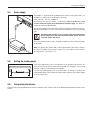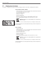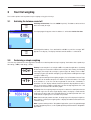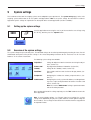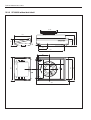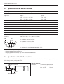
1
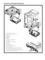
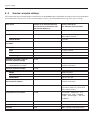
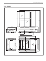
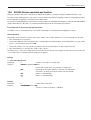
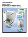
Operating Instructions
METTLER TOLEDO
Excellence Plus XP Comparator Balances
XP2004S, XP2003S, XP5003S, XP10003S
www.mt.com/support
LEERE SEITE
Overview of XP Comparator Balances
7
9
8
11
5
12
F
6
F
9
7
19
5
11
4
12
F
3
1
2
1 Terminal (for details s. Section 4)
2 Display (Touch-sensitive “Touch Screen”)
4
3
F
3
3 Operating keys
4 SmartSens sensors
5 Type name
6 Draft shield
7 Levelmatic
8 Draft shield element (XP10003S)
9 Level indicator
10 Fastening point for anti-theft device
11 Safety foots
12 Leveling screw
13 RS232C serial interface
14 Slot for second interface (optional)
15 Socket for AC adapter
14
15
18
17
16 Aux 1 (connection for “ErgoSens”, hand- or foot-switch)
17 Aux 2 (connection for “ErgoSens”, hand- or foot-switch)
18 Fastening for auxiliary display stand or terminal stand (optional)
19 Handle for operation of the draft-shield door
16
13
10
11
Contents
4
Contents
1
Getting to know your balance .......................................................................................................................... 6
1.1
1.2
1.3
1.4
Introduction .................................................................................................................................................... 6
Introducing the XP comparator balances ............................................................................................................ 6
Conventions and symbols used in these operating instructions ............................................................................. 6
Safety first ...................................................................................................................................................... 7
2
Setting up the balance .................................................................................................................................... 8
2.1
2.1.1
2.1.2
2.2
2.2.1
2.2.2
2.3
2.3.1
2.3.2
2.4
2.5
2.6
2.7
Unpacking and checking the standard equipment ............................................................................................... 8
Unpacking the draft shield ................................................................................................................................ 8
The following components are standard equipment: ............................................................................................ 9
Setting up the balance ................................................................................................................................... 10
Installing the balance cable in the terminal ....................................................................................................... 10
Installing the draft shield and weighing pan ...................................................................................................... 11
Selecting the location and leveling the balance ................................................................................................. 12
Selecting the location ..................................................................................................................................... 12
Leveling the balance ...................................................................................................................................... 12
Power supply ................................................................................................................................................ 13
Setting the reading angle ................................................................................................................................ 13
Transporting the balance ................................................................................................................................ 13
Weighing below the balance ........................................................................................................................... 14
3
Your first weighing ....................................................................................................................................... 15
3.1
3.2
Switching the balance on and off .................................................................................................................... 15
Performing a simple weighing ........................................................................................................................ 15
4
Basic principles for using the terminal and the software ................................................................................. 16
4.1
4.2
Overview of the terminal ................................................................................................................................. 16
The display ................................................................................................................................................... 17
5
System settings ........................................................................................................................................... 19
5.1
5.2
5.3
Calling up the system settings ........................................................................................................................ 19
Overview of the system settings ...................................................................................................................... 19
Overview of system settings ............................................................................................................................ 20
6
User settings ............................................................................................................................................... 22
6.1
6.2
6.3
Calling up user-specific settings ...................................................................................................................... 22
Overview of the user-specific settings ............................................................................................................... 22
Overview of “User-specific settings” ................................................................................................................. 23
7
The “Weighing” application .......................................................................................................................... 24
7.1
Selecting the application ................................................................................................................................ 24
8
The “WeighCom” application ........................................................................................................................ 25
8.1
8.2
Introduction to the “WeighCom” application ...................................................................................................... 25
Selecting the application ................................................................................................................................ 25
Contents
5
9
Software updates ......................................................................................................................................... 26
9.1
9.2
9.3
9.4
9.5
Operating principle ........................................................................................................................................ 26
Requirements ................................................................................................................................................ 26
Loading software updates from the Internet ....................................................................................................... 26
Loading the new software into the balance ....................................................................................................... 27
Saving and reloading balance settings ............................................................................................................. 29
10
Error and status messages ............................................................................................................................ 30
10.1
10.2
10.3
Error messages occurring during normal operation ........................................................................................... 30
Further error messages .................................................................................................................................. 30
Status messages ........................................................................................................................................... 31
11
Cleaning and service .................................................................................................................................... 32
11.1
Cleaning the draft shield ................................................................................................................................. 33
12
Technical data and accessories ..................................................................................................................... 34
12.1
12.2
12.3
12.3.1
12.3.2
12.3.3
12.3.4
12.4
12.5
12.6
12.7
General data ................................................................................................................................................. 34
Model-specific data ....................................................................................................................................... 35
Dimensions .................................................................................................................................................. 36
XP2004S and XP5003S ................................................................................................................................ 36
XP2003S ..................................................................................................................................................... 37
XP10003S without draft shield ....................................................................................................................... 38
XP draft shield W12 ...................................................................................................................................... 39
Specifications of the RS232C interface ............................................................................................................. 40
Specification of the “Aux” connections .............................................................................................................. 40
MT-SICS Interface commands and functions ..................................................................................................... 41
Accessories .................................................................................................................................................. 43
Getting to know your balance
6
1
Getting to know your balance
In this Section you will be given basic information about your balance. Please read right through this Section carefully even if you
already have experience with METTLER TOLEDO balances; please pay special attention to the safety warnings!
1.1
Introduction
Thank you for choosing a METTLER TOLEDO comparator balance.
Comparator balances combine a large number of weighing and adjustment possibilities with exceptionally convenient operation.
With these balances software updates can be downloaded from the Internet and loaded into the balance.
These Operating Instructions apply to the XP2004S, XP2003S, XP5003S, and XP10003S comparator balances. Please read these
Operating Instructions carefully right through so that you can derive maximum benefit from all the possibilities your comparator
balance offers.
You will find instructions for using the “WeighCom” application for mass comparison, which is delivered with the comparator balance,
in the enclosed “WeighCom Application” operating instructions.
1.2
Introducing the XP comparator balances
The XP family of comparator balances comprises various models (XP2004S, XP2003S, XP5003S, XP10003S) which differ in their
weighing range and resolution.
All the comparator balances have the following features:
– Touch-sensitive “TouchScreen” graphics terminal with color display.
– Built-in applications for mass comparison (“WeighCom”) as well as for normal weighing. Further applications can be downloaded
from the Internet onto your computer as required, and from there into the comparator balance.
– Built-in RS232C interface.
– Adjustment (calibration and linearization) with internal weight at a keystroke.
– Two programmable sensors for hands-off operation (“SmartSens”) to speed up frequently recurring tasks.
1.3
Conventions and symbols used in these operating instructions
The following conventions apply throughout these operating instructions:
– Key designations are indicated by double angular parentheses (e.g. «On/Off» or «E»).
These symbols indicate safety notes and hazard warnings which, if ignored, can cause
personal danger to the user, damage to the balance or other equipment, or malfunctioning of the balance.
This symbol indicates additional information and notes. These make working with your
balance easier, as well as ensuring that you use it correctly and economically.
Getting to know your balance
7
1.4
Safety first
Always operate and use your balance only in accordance with the instructions contained in this manual.
The instructions for setting up your new balance must be strictly observed.
If the instrument is not used according to the manufacturer's Operating Instructions, protection of the instrument may be
impaired (see also § 5.4.4 of EN 60101:01).
The balance may only be used in enclosed interior rooms. It is not permitted to use the
balance in hazardous environments.
Use only the AC adapter delivered with your balance, and check that the voltage printed
on it is the same as your local power supply voltage. Only plug the adapter into a socket
which is grounded.
Do not use sharply pointed objects to operate the keyboard of your balance!
Although your balance is very ruggedly constructed, it is nevertheless a precision
instrument. Treat it with corresponding care.
Do not open the balance: It does not contain any parts which can be maintained,
repaired, or replaced by the user. If you ever have problems with your balance, contact
your METTLER TOLEDO dealer.
Use only balance accessories and peripheral devices from METTLER TOLEDO; they are
optimally adapted to your balance.
Disposal: The instrument must be disposed of according to the respective customerand country-specific regulations.
Setting up the balance
8
2
Setting up the balance
This Section describes how to unpack your new balance, set it up and prepare it for operation. On completion of the steps described
in this Section, your balance is ready for operation.
Note: The balance must be disconnected from the power supply when carrying out all setup and mounting
work, as well as when the housing of the weighing terminal is opened during everyday operation.
2.1
Unpacking and checking the standard equipment
Open the packaging and carefully remove all components.
2.1.1
Unpacking the draft shield
– Place the draft shield on a clean surface.
A
– Turn so the cover (A) is vertically on top.
– Lift the carton (B) off over the handle and the pull the carton off
toward the back.
B
Note: Hold the glass panels firmly so they do not get
pulled off and fall to the floor!
– Close the cover (A) again.
– Push all the glass panels as far as they will go to the back.
– Insert the bottom plate (C).
C
Note: For installation of the draft shield on the XP10003S
comparator balance, separate installation instructions
are enclosed.
Setting up the balance
9
2.1.2
The following components are standard equipment:
– Weighing platform and terminal
– Draft shield
– Bottom plate
– Weighing pan support
– Weighing pan 127 x 127 mm
– Levelmatic Ø130 mm (all models except XP2003S)
– Draft shield element (XP10003S only)
– Extension cable to the terminal (XP10003S only)
– AC adapter and country-specific power cable
– Operating instructions for XP comparators balance, Excellence Plus XP precision balances, and the “WeighCom” application
– Production certificate
– EC declaration of conformity
Setting up the balance
10
2.2
Setting up the balance
The terminal is identical for all XP comparator balances.
2.2.1
Installing the balance cable in the terminal
A
A
– Place the terminal on the operating surface.
Note: Ensure that a soft, clean surface is used so as not to damage the terminal
surface.
– Open the housing by pressing the 2 buttons (A) for adjusting the terminal and
swiveling the housing base upwards.
– Pull the cable with the retaining ring (B) through the opening on the housing base
(see diagram).
B
– Return the terminal to its normal position and open it so that the cable can be
accessed.
C
– Insert the cable into the top housing (C).
– Close both parts of the housing until the retaining ring (B) is positioned in the cable
opening of the housing base.
B
– Place the retaining ring (B) behind the two guideways and check that it is secure
(tension relief).
B
Note: Before closing the housing, always check that the plug is inserted
correctly into the terminal plug-in connection.
– Now close the housing by pressing the two buttons (A) for adjusting the terminal
until the housing base engages in the top housing.
A
A
Setting up the balance
11
2.2.2
Installing the draft shield and weighing pan
Place the following components on the balance in the specified order:
Important: Always use both hands to hold the draft shield by the upper bars
and in a vertical position.
3
– Place the draft shield (1) on the balance and then open the side doors.
– Insert the bottom plate (2), if not already inserted (Section 2.1.1)!
– Place the Levelmatic (3) in position.
2
1
Note: For installation of the draft shield on the XP10003S comparator
balance, separate installation instructions are enclosed.
Note: Cleaning the draft shield, see Section 11.1
F
F
XP10003S comparator balance :
Place the following components on the balance in the specified order:
– Centering plate (1)
3
– Cover (2)
– Levelmatic (3)
2
1
Note: You can also work without the centering plate (1) and cover (2).
However, depending on the ambient conditions, the display of the results
may be slightly more unstable.
F
F
Setting up the balance
12
2.3
Selecting the location and leveling the balance
Your balance is a precision instrument and will thank you for an optimum location with high accuracy and dependability.
2.3.1
Selecting the location
Select a stable, vibration-free position that is as horizontal as possible. If the balance
does not immediately stand perfectly horizontally, it must be leveled before it is used
for the first time (Section 2.3.2). The surface must be able to safely carry the weight of
a fully loaded balance.
Observe ambient conditions (see Section 12.1).
Avoid the following:
– Direct sunlight
– Powerful drafts (e.g. from fans or air conditioners)
– Excessive temperature fluctuations
2.3.2
Leveling the balance
Align the balance horizontally by turning both leveling screws on the front of the balance
housing until the air bubble is in the inner circle of the level indicator.
Example: The position of the air bubble illustrates which leveling screw you need to turn
and in which direction so that the air bubble moves to the center.
In this example, turn the left leveling screw counterclockwise.
L = left leveling screw, R = right leveling screw
Setting up the balance
13
2.4
Power supply
Your balance is supplied with an AC adapter and a country-specific power cable. The
AC adapter is suitable for all line voltages in the range:
100 - 240 VAC, -10/+15%, 50/60 Hz.
Check whether the local line voltage is in this range. If this is not the case, on no
account connect the balance or the AC adapter to the power supply, but contact the
responsible METTLER TOLEDO dealer.
Connect the AC adapter to the connection socket on the back of your balance (see figure)
and to the power supply. Secure the connection to your balance by screwing the plug
tight.
Important: Install the cable in such a way that it will not be damaged and
will not hinder day-to-day work. Ensure that the AC adapter can never
come into contact with liquids.
Once connected to the power supply, the balance performs a self-test and is then ready
for operation.
Note: If the display area remains dark, even though the power connection is working,
disconnect the balance from the power supply, then check that the terminal cable is
inserted correctly (see Section 2.2.1).
2.5
Setting the reading angle
For a steep reading angle, press in the two buttons (A) on the back of the terminal. The
top of the terminal can then be slowly pulled upwards until it engages in the desired
position. A total of 3 setting positions are available.
A
2.6
A
To set a lower reading angle, press in the two buttons (A) and press the top of the
terminal downwards. Release both of the buttons and the top of the terminal will engage
in the desired position.
Transporting the balance
Before you move your comparator balance to a new location, please contact the METTLER TOLEDO organizationor distributor in your
country.
Setting up the balance
14
2.7
Weighing below the balance
Your balance is equipped with a hanger for carrying out weighings below the work surface (weighing below the balance).
Models XP2004S, XP2003S, XP5003S
– Switch off the balance, unscrew the AC adapter cable connection from the back of
the weighing platform and remove the cable.
– Remove any interface cable.
– Remove the Levelmatic.
– Remove the bottom plate.
– Carefully lift the draft shield from the weighing platform and put it aside.
– Tilt the weighing platform backwards until the cover plate (B) is visible.
Important: Do not place the weighing platform on the supporting cone
for the Levelmatic.
– Remove the 2 screws (A) and the cover plate (B). The hanger is now accessible.
A
B
Then return the balance to its normal position and simply reinstall all components in
the reverse order.
Model XP10003S
– Lift off the draft shield.
– Switch off the balance, unscrew the AC adapter cable connection from the back of
the weighing platform and remove the cable.
– Remove any interface cable.
– Remove the draft shield element
– Remove the Levelmatic.
– Tilt the weighing platform backwards until the cover plate (B) is visible.
Important: Do not place the weighing platform on the supporting cone
for the Levelmatic.
– Remove the 2 screws (A) and the cover plate (B). The hanger is now accessible.
Then return the balance to its normal position and simply reinstall all components in
the reverse order.
Your first weighing
15
3
Your first weighing
This Section explains how to perform simple weighings using just a few keys.
3.1
Switching the balance on and off
On
Switching on the balance: Press the «On/Off» key briefly. The balance carries out a test
and is then ready to weigh.
Off
The display opposite appears when the balance is switched on for the first time.
On
Switching off the balance: Press and hold the «On/Off» key until the message “OFF”
appears in the display. The display then fades and the balance is switched off.
Off
3.2
Performing a simple weighing
Just a few keys located in the lower part of the terminal are needed to perform a simple weighing. Your balance has separate keys
for zeroing («G») and taring («H»).
G
H
Zeroing: A new zero point is set using the«G» key and all weight values (including
the tare weight) are measured in relation to this zero point. After zeroing, the following
values apply: tare weight = 0, net weight (= gross weight) = 0. Always use the «G»
zeroing keys before you start with a weighing, especially before recording a tare weight
(using the «H» key).
Taring: If you are working with a weighing container, first set the balance to zero. Place
the container on the balance and press the «H» key to tare the balance. The weight
of the container is set as the new tare weight and the current tare (if available) is
overwritten. The “Net” display indicates that all weight values displayed are net values.
Note: If you try to tare a negative weight value, an error message appears as this is not
permitted. Set the balance to zero and try again.
Weighing: Place the weighing sample on the pan. As soon as the stability detector icon
(the small ring to the left of the weight display) fades, the display is stable and the
weighing result can be read. In the illustration opposite, the stability detector icon is still
visible and the weighing result is therefore not yet stable.
Note: While the display remains unstable, the weighing result is displayed in light blue.
Once stability is reached, the weighing value is displayed in dark blue and can thus be
read more easily.
Note: If you are working with the “WeighCom” application, you will be guided through
the mass comparison process (see the separate operating instructions for the “WeighCom”
application).
Basic principles for using the terminal and the software
16
4
Basic principles for using the terminal and the software
This section explains the operating and display elements of your terminal. Please read this section through carefully. It is the basis
for all operating steps which are referred to in later sections.
You will find explanations of the operating concept of the software, typical work processes, and the security system of your balance
in Chapter 4 of the operating instructions for the “Excellence Plus XP Precision Balance”.
4.1
Overview of the terminal
In this Section we start by introducing the operating elements of the terminal (with the exception of the «On/Off», «G» and «H»
keys, which were already described in the previous Section).
1
2
6
3
7
4
5
4
8
EXCELLENCE PLUS
1
1 SmartSens
Each of these two contact-free sensors can be assigned a key or menu function (e.g. zeroing, printing or
changing the display resolution, etc.). To initiate the appropriate function, move your hand over the relevant
sensor (maximum distance of approx. 5 cm). The sensor beeps to confirm that it has recognized the command
and is carrying it out. Both sensors are deactivated ex works.
A
2 «A» key
This key can be used to return to the “Home” user profile from any menu level in any application (additional
information on applications and user profiles can be found later in this Section).
B
3 «B» key
This key can be used to call up the desired user profile. Different settings can be stored in a user profile. This
enables the optimum adaptation of the balance to the user or a particular weighing task.
4 Status bar
When the left or right SmartSens is assigned a key function, the corresponding icon («F,» «G» or «H»)
lights up green in the left or right status bar. If the “F” icon lights up, one of the menu functions has been assigned
to the corresponding SmartSens.
The yellow LED at the very bottom of the status bar lights up briefly to confirm when a key has been pressed
or a menu function carried out. This visual acknowledgment is deactivated ex works.
Basic principles for using the terminal and the software
17
C
5 «C» key
This key can be used to define the basic settings for each user profile. These settings apply to all applications
used by the current user.
D
6 «D» key
Your balance is supplied with two standard applications ex works (one for normal weighing and “WeighCom”
for mass comparisons). This key can be used to select the application you would like to work with.
E
7 «E» key
Each application can be ideally adapted to the current task using a number of settings. This key can be used
to call up the menus for configuring the active application.
F
8 «F» key
Pressing this key transmits data via the interface, e.g. to a printer. However, other devices - for example, a
PC - can also be connected. The data to be transmitted can be freely defined.
4.2
The display
Your terminal's illuminated, colorful display is a “touch screen”, that is to say, a touch-sensitive screen. Not only can you read data,
but you can also make settings and execute functions by touching the surface of the screen.
2
1
5
3
4
5a
5b
The display is divided into different zones (the figure shows the display with information
fields and “SmartTrac”):
1 The current active application is indicated in the top left of the display. By touching
this zone you can call up the menu in which you can select the desired application
(this menu can also be accessed using the «D» key).
2 Display of the current date. The date can be changed by touching this zone.
3 Display of the current time. The time can be changed by touching this zone.
4 Status icons: These symbols appear as needed and indicate any special needs of
the balance (e.g., needs servicing, needs adjustment, change batteries, etc.). A list
of all status icons can be found in Section 15.3.
5 The current weighing result appears in this zone. If the weighing unit is touched
(5b), a window appears, in which the desired weighing unit can be selected.
If the weighing result is touched (5a), a window appears, in which the current gross
weighing result is displayed. This can be useful if the weighing result has to be read
from a distance. This window can be closed again by pressing the “OK” button.
Basic principles for using the terminal and the software
18
6 Additional information (information fields) for the active application, which makes
your work easier, are displayed in this area.
6
7
8
7 The “SmartTrac,” a graphic weighing-in aid, which shows the used and remaining
available weighing capacity at a glance, is displayed in this zone. Different display
types for the “SmartTrac” can be selected or switched off completely by touching this
area.
8 This area is reserved for the function keys, which provide direct access to the most
frequently required functions and settings for the active application. If more than
5 function keys are activated, you can switch between them using the arrow keys
(not shown in the figure).
System settings
19
5
System settings
This Section describes how the weighing system can be adapted to your requirements. The system settings apply to the entire
weighing system and therefore to all user profiles and applications. Note: User-specific settings are described in Section 6.
Application-specific settings are explained in the description of the relevant application (Section 7 onwards).
5.1
Calling up the system settings
D
▼
5.2
C
Select the application menu using the «D» key or the menu for the user settings using
the «C» key, and then press the “System” button.
▼
Overview of the system settings
The system settings are represented by icons. The individual settings can be called up and changed by touching the icons. You will
find detailed descriptions of the possible settings in the enclosed operating instructions for the “Excellence Plus XP Precision
Balances” in the sections listed below.
The following system settings are available:
“Adjust/Test”:
Settings for adjustment and test functions for testing the adjustment (Section 5.3).
“Balance Info”:
Display/printout of balance information (Section 5.4).
“Standby”:
Settings for the “Standby” mode (Section 5.5).
“Date/Time”:
Entry of date and time and selection of display format (Section 5.6).
“Peripherals”:
Configuring the interface for various peripheral devices (Section 5.7).
“Administrator”:
Configuring the security system of the balance, including allocating access rights and passwords for balance functions and
menus (Section 5.8).
Note: Access to the “Administrator” settings is protected ex works
with an ID and a password.
Once you have defined all the settings required, press the “Exit” button to return to the
active application.
Note: If special interface options (e.g. Ethernet) have been installed, the systems
settings menu additionally displays the symbol shown at left with global settings for
these interfaces. These settings are described in the instructions that were supplied with
the optional interface.
System settings
20
5.3
Overview of system settings
In the table below you will find the factory settings for the XP comparator balances along with the chapters of the enclosed operating
instructions for the “Excellence Plus XP Precision Balances” where you will find details of the respective system settings.
Description
Chapter in the enclosed operating
instructions for the ”Exellence Plus
XP Precision Balances”
Adjustment history
5.3.1
Factory setting for all
XP comparator balance models
“Selection”
“Manual Adjust.”, “Temperature” and
“Time Adjust” activated.
“Display Records”
“Last 50”
Fully automatic adjustment function
“ProFACT”
5.3.2
“ProFACT”
“Off” (ProFACT switched off)
“Days”
All days activated
“Temp. Criterion”
“1 Kelvin”
“Protocol Trigger”
“On”
Automatic adjustment using an
external adjustment weight
5.3.3
Automatic adjustment using an
external adjustment weight
External adjustment weights
“Off” (Automatic external adjustment
function switched off )
5.3.5
“Weight”
Model-dependent
“ID”
No entry specified
“Certificate No.”
No entry specified
Automatic adjustment testing using
an external test weight
5.3.6
“Off” (Automatic external adjustment
function switched off )
External test weights
5.3.8
For all 5 external test weights: weight
depends on model, no entries for ID
and certificate number
Adjustment and test reports
5.3.9
Activated are: “Date/Time”, “User”,
“Balance type”, “SNR”, “Nominal
weight”, “Actual weight”, “Diff.” and
“Signature”
Balance Information
5.4
“Balance ID”
Standby
No entry specified
5.5
“Off” (“Standby” mode deactivated)
System settings
21
Description
Chapter in the enclosed operating
instructions for the ”Exellence Plus
XP Precision Balances”
Date and time
5.6
Factory setting for all
XP comparator balance models
“Date Format”
“D.MMM.YYYY”
“Time Format”
“24:MM”
Peripheral devices
5.7
“Host”: 9600 baud, 8 data bits/no
parity, 1 stop bit, Xon/Xoff record, end
of line character <CR><LF>, ANSI/
Windows character set, “Continuous
mode” = off).
User access rights
5.8.3
“No Protection” (all menu areas are freely
accessible)
Recording security-related operations
5.8.4
“Off” (Recording deactivated)
Changing the password
5.8.5
“Off” (Reminder function deactivated)
User settings
22
6
User settings
This Section describes how to set basic settings for each user. This enables the balance to be adapted to the user’s work technique
and to specific tasks. The settings are stored under the active user profile and apply when working with all applications within this
profile. When a user profile is called up, the relevant settings are loaded automatically.
6.1
Calling up user-specific settings
C
6.2
First, ensure that the correct user profile is active, i.e. the one whose basic settings you
would like to modify. The 8 user profiles are available under the «B» key.
Use the «C» key to select the menu for the user-specific settings. Note: If access to the
menu has been protected by the administrator, you must enter the appropriate ID and
password.
Overview of the user-specific settings
The user-specific settings are represented by icons. The individual settings can be called up and changed by touching the icons. You
will find detailed descriptions of the possible settings in the enclosed operating instructions for the “Excellence Plus XP Precision
Balances” in the sections listed below.
The following user-specific settings are available:
“Wgh param”:
Settings for adapting the balance to specific weighing tasks
(Section 6.3).
“User”:
User information (name, password, etc.), (Section 6.4).
“Terminal”:
Settings for the display (brightness, etc.) and the behavior
of the terminal (Section 6.5).
“User Reset”:
Resets the user-specific settings to the factory default
settings (Section 6.6).
Once you have defined all the settings required, press the “Exit” button to return to the
active application.
User settings
23
6.3
Overview of “User-specific settings”
In the table below you will find the factory user-specific settings for the XP comparator balances along with the chapters of the enclosed
operating instructions for the “Excellence Plus XP Precision Balances” where you will find details of the respective system settings.
Description
Chapter in the enclosed operating
instructions for the ”Exellence Plus
XP Precision Balances”
Defining weighing parameters
6.3
Factory setting for all XP comparator
balance models
“Weighing Mode” *
“Universal”
“Environment”
“Standard”
“Measured Value Release”
“Reliable + Fast”
“AutoZero”
“Off” (switched off)
Entering user data
6.4
“User Name”
“User x” (x=1..7) and “Home”
“Language”
“English”
“User ID” and “Password”
“0” (Null) for the “Home” profile
“1” for the “User 1” profile
“7” for the “User 7” profile
Terminal settings
6.5
“Brightness”
80%
“Contrast”
50%
“Color Selection”
“Color palette 1
(blue with soft contrast)”
“Sound”
70%
“Touch Adjustment”
“On”
“Optical key feedback”
“Off”
* In Weighing Mode, only the “Universal” and “Sensor Mode” settings are available.
The “Weighing” application
24
7
The “Weighing” application
You wiil find practical information about working with the “Weighing” application along with the possible settings in Chapter 7 of
the enclosed operating instructions for the “Excellence Plus XP Precision Balances”. Please note that all settings you make for the
“Weighing” application will be stored under the active user profile. You must therefore make sure that you have selected the
correct user profile before you make any settings.
7.1
Selecting the application
D
If the “Weighing” application is not already active, press the «D» key. Touch the
“Weighing” icon in the selection window. The balance is now ready for weighing.
The “WeigCom” application
25
8
The “WeighCom” application
You will find practical information about working with the “WeighCom” application along with the possible settings in the separate
operating instructions “WeighComApplication for XP Comparator Balances”.
Please note that all settings you make for the “WeighCom” application will be stored under the active user profile. You must
therefore make sure that you have selected the correct user profile before you make any settings.
8.1
Introduction to the “WeighCom” application
So that weights can be traced back to the prototype kilogram, the mass of the weight being determined must be compared with the
mass of the reference weight. This procedure requires great care by the operator so that no weights are confused. On the XP2004S,
XP2003S, XP5003S, and XP10003S comparator balances, the “WeighCom” application guides the user through this masscomparison weighing with weights of any manufacturer and thereby ensures the certainty and reliability of the mass-comparison
weighing.
8.2
Selecting the application
D
If the “WeighCom” application is not already active, press the «D» key. Touch the
“WeighCom” icon in the selection window. The comparator balance is then ready for
the mass-comparison weighing.
Software Updates
26
9
Software updates
METTLER TOLEDO is continuously improving its balance software for the benefit of customers. So that you, the customer, can benefit
quickly and easily from further developments, METTLER TOLEDO makes the latest software versions available on the Internet. The
Software made available on the Internet has been developed and tested by Mettler-Toledo GmbH using processes that meet the
guidelines of ISO 9001. Mettler-Toledo GmbH does not, however, accept liability for consequences that might arise from using the
software.
9.1
Operating principle
You will find all the relevant information and updates for your balance on the METTLER TOLEDO Web site at the following address:
www.mt.com/balance-support
We recommend that you create a bookmark for this address in your Web browser, so that you can access the site directly in the future.
A program known as the “e-Loader II” is loaded onto your computer together with the software update. You can use this program
to download the software to the balance. The “e Loader II” can also save the settings in your balance before the new software is
downloaded to it. You can reload the saved settings into the balance after the software is downloaded.
If the selected update includes an application that is not described in these instructions (or that has been updated in the meantime)
you can download the corresponding instructions in Adobe Acrobat® PDF format. You will need Adobe Acrobat Reader® to open PDF
documents (www.adobe.com).
The following Sections offer detailed information on obtaining software updates from the Internet and downloading software into the
balance.
9.2
Requirements
The minimum requirements for obtaining applications from the Internet and downloading them into your balance are as follows:
– PC with Microsoft Windows® operating system (Version 98, 98SE, ME, NT 4.0, 2000 or XP)
– Internet connection and Web browser
– PC - balance connection cable (RS232 cable, 9-pin sub-D plug m/f, order number 11101051)
9.3
Loading software updates from the Internet
The first step is to download the software from the Internet onto your computer:
Connect to the Internet.
In your browser, select “www.mt.com/balance-support” as the Internet address, and then click the “Software” link.
Click on the appropriate update package for your balance.
Enter the information required for registration.
Load the software package onto your computer.
Before you install the “e-Loader II” software program, please read Section 9.4.
Software Updates
27
9.4
Loading the new software into the balance
Before you can load the software obtained from the Internet into the balance, you must connect the balance through the RS232 cable
to the serial interface of your computer. Note: The cable must always be connected to the RS232C interface that is permanently
fitted at the factory!
Set the interface on the balance to the following values (detailed information on these system settings can be found in Section 5.6):
Select “Host” as the peripheral device, and then set the following communication parameters: Baud rate: 9600, parity: 8 bits/none,
handshake: none, end of line: <CR><LF>, character set: ANSI/WIN.
Make sure that the corresponding communication parameters on your computer are set to the same values.
Start the “e-Loader II VXXX” information program that you obtained from the Internet (“XXX” is a place holder for the version number).
This program installs the e-Loader on your computer.
Follow the instructions, which will take you step-by-step through the installation.
The e-Loader II will start automatically after installation. This diagram illustrates the
starting screen for the e-Loader II.
You are asked to select the interface on the computer to which the balance is connected
(if necessary, this setting can be changed at any later time in the “Options” –> “COM
Port” menu).
Having selected the interface, click “Proceed”.
A message window appears, reminding you that the standard RS232C interface on the
balance is to be used. The interface settings are also listed once again (see above).
Close the window by clicking on “OK”.
Under the factory settings, the e-Loader II guides you through the updating process using
English as the language. If you wish, you can enter the “Options” –> “Language” menu
to select one of the other available languages. The e-Loader II will then display all the
instructions and notes in the language that you have chosen. The following diagrams
and information are based on the English version.
Before you update the software of your balance, please check in the “Help” menu that
the communication with the balance is functioning. (In the example shown here, the eLoader II is confirming that a balance is connected.)
If the e-Loader II reports that a balance is not connected, first check whether the correct
interface, with the right setting, has been selected, and then, if necessary, check that the
communication settings of the computer and the balance correspond.
Software Updates
28
You can begin the updating process once you have made the necessary setttings and
checked that the connection is operating. Click on “Start Software Update Procedure”
to do this. Follow the instructions provided by e-Loader II; these will guide you step-bystep through the updating process. e-Loader II will ask you if you want to save the
current balance settings on your computer. We recommend that you carry out this data
backup. This will save you from having to enter all the settings again, since they will
all be returned to the factory settings in the course of the update. At the end of the
updating procedure, e-Loader II will ask whether the saved data should be reloaded
back into the balance.
Before you start the actual updating operation, you have the possibility to define a
Secure ID to protect the balance against unauthorized software updating operations.
To do this, click on the “Create Secure-ID” button. If you do not wish to use this function,
click on “Continue”.
The Secure ID is balance-specific and saved in the balance. Please make a note of the
Secure ID and keep it in a safe place. If you forget the Secure ID, no further updates can
be made to the balance.
Define the “Secure ID” and confirm it by entering it again in the field provided. Then click
on “Continue”.
The e-Loader II now displays a list of the updates which have been performed. In this
window you can enter a user identification “User ID” so that it is subsequently possible
to trace who performed the software updating operation.
Click on “Continue” to start the updating operation.
The balance software consists of a terminal software and a weighing-platform software.
After the terminal software has been loaded, updating of the weighing-platform software
begins. Here, too, you can define a Secure ID and enter a User ID.
Changing the Secure ID: The Secure ID can be changed when a new software updating
operation is started. To do so, click on the “Change Secure ID” field. You can now enter
a new Secure ID. If you leave the field empty, the Secure ID is deleted and no longer
active.
When the updating process has been completed you can close e-Loader II. Your
balance will now operate with the newly loaded software.
Software Updates
29
9.5
Saving and reloading balance settings
In addition to balance software updates, e-Loader II also offers a function whereby the current balance settings can be copied to a
PC. This allows you to have a backup copy of your settings available at all times. This function can also be used to copy the settings
from one balance to another.
In order to save the current balance settings on a PC, start e-Loader II and call up the
data backup function, as shown in the diagram here.
e-Loader II suggests a path and a name for the backup file. You can change these
designations via the “Change” key.
Note: e-Loader suggests a combination of the current date and the current time as a
name for the backup file, and the file extension “.dat”. (For example:
“2004_03_08_13_21.dat” for a backup file that was created on March 8, 2004 at
13.21 hours.) You are free to alter the file name, if you wish, but not the “.dat” extension.
Click on “Start” to begin the data backup. Successful completion of the backup is
confirmed on the display.
To copy the balance settings from the PC back into the balance, call the reload function,
as illustrated here.
Having started the reload function you can select, via the “Browse” button, the settings
file to be loaded back into the balance, after which you can begin the transfer process
with “Start”. Keep in mind that this will cause all the settings saved in the balance
to be overwritten!
Error and status messages
30
10
Error and status messages
10.1
Error messages occurring during normal operation
Most error messages appear in plain text directly in the respective application, and usually accompanied by a text describing how
to correct the error. Error messages of this type are self-explanatory and therefore not mentioned below.
The following error messages can appear instead of the weighing result:
Overload
The weight on the pan exceeds the weighing capacity of the balance. Reduce the weight
on the weighing pan.
Underload
Ensure that the weighing pan is correctly in place, can move freely, and does not catch
on the draft cover.
Error when switching on or zeroing «G» (weight display flashes)
When the balance was switched on (i.e. when it was connected to the power supply
or switched on from standby mode) or upon zeroing, one or more limits were exceeded.
The usual reason for this message to appear is when there is a weight on the weighing
pan when the balance is switched on. Remove the weight.
Taring or zeroing was interrupted
A taring or zeroing operation was aborted because a stable result was not obtained
during the stabilization time (“Timeout”). Close the doors of the draft shield (if your
balance is equipped with a draft shield) and check the working location (vibrations,
drafts). Press “OK” and repeat the taring («H») or zeroing («G»).
10.2
Further error messages
If any error messages appear (“Error x”) other than those described above, please contact your METTLER TOLEDO dealer.
Error and status messages
31
10.3
Status messages
Status messages are displayed by means of small icons (symbols) in the top right of the display (under the date and time)
(Section 4.2). The status icons indicate the following:
The balance would like to carry out a fully automatic ProFACT adjustment but is unable because another
operating sequence is running. The adjustment is carried out as soon as the balance is unloaded, the display
becomes stable, and no key has been pressed for 2 minutes (see Chapter 7.4.1 in the enclosed operating
instructions “Excellence Plus XP Precision Balances”). The status icon disappears after the adjustment is
successfully completed.
You have specified in the system settings that the balance should automatically request an adjustment using
an external weight (see Chapter 5.3.3 in the enclosed operating instructions “Excellence Plus XP Precision
Balances”). The balance uses this status icon and a corresponding message to prompt you to carry out the
adjustment. The status icon fades after the adjustment is successfully concluded, or if you indicate your
decision not to carry out the adjustment (see Chapter 7.4.3 in the enclosed operating instructions “Excellence
Plus XP Precision Balances”).
You have specified in the system settings that the balance should automatically request adjustment testing
using an external weight (see Chapter 5.3.6 in the enclosed operating instructions “Excellence Plus XP
Precision Balances”). The balance uses this status icon and a corresponding message to prompt you to carry
out the test. The status icon fades after the adjustment is successfully concluded, or if you indicate your decision
not to carry out the adjustment (see Chapter 7.4.5 in the enclosed operating instructions “Excellence Plus XP
Precision Balances”).
“MinWeigh” is active (see Chapter 7.2.13 in the enclosed operating instructions “Excellence Plus XP Precision
Balances”). This status icon informs you that the minimum weight value for the current tare has not yet been
reached, and that the current weight value is outside the tolerance range specified by your quality assurance
system. The status icon fades as soon as the minimum weight value has been reached (see Chapter 7.3.5
in the enclosed operating instructions “Excellence Plus XP Precision Balances”).
It is time for the next scheduled test of the “MinWeigh” function (see Chapter 7.3.5 in the enclosed operating
instructions “Excellence Plus XP Precision Balances”). Contact your dealer’s customer service department as
soon as possible to have a service technician run the test.
The battery in your balance must be replaced. This battery ensures that the date and time are not lost when
the balance is disconnected from the network. Contact your dealer’s service department as soon as possible
to have a service technician change the battery.
Your balance is due for servicing. Contact your dealer’s customer service department as soon as possible to
have a technician service your balance.
Cleaning and service
32
11
Cleaning and service
Every now and then, clean the weighing pan, draft shield element, bottom plate, draft shield (depending on the model), housing and
terminal of your balance using a damp cloth. Your balance is made from high-quality, durable materials and can therefore be cleaned
with a standard, mild cleaning agent.
To thoroughly clean the draft shield glasses, remove the draft shield (see Section 11.1).
When reinserting the glass, ensure that it is in the correct position (see Section 2).
Please observe the following notes
– On no account use cleaning agents, which contain solvents or abrasive ingredients, as this can result in
damage to the terminal overlay.
– Ensure that no liquid comes into contact with the balance, the terminal or the AC adapter.
– Never open the balance, terminal or AC adapter - they contain no components, which can be cleaned, repaired
or replaced by the user.
Please contact your METTLER TOLEDO dealer for details of the available service options. Regular servicing by an
authorized service engineer ensures constant accuracy for years to come and prolongs the service life of your
balance.
Cleaning and service
33
11.1
Cleaning the draft shield
Remove the following parts:
– Remove the Levelmatic.
– Lift the draft shield off the balance and place it on a clean surface.
– Remove the bottom plate.
– Push all the glasses back as far as they
will go.
– Turn the cover (A) to the front.
– Pull the top glass toward the back and
off.
– Pull the side glasses toward the back
and off.
A
Note: Always hold the 2 parallel guided glasses (side glasses and top glasses) together
with one hand (illustrations
below).
– Clean all parts then reassemble the
draft shield in the reverse order.
B
B
Insert glasses:
Note: Always hold the 2 parallel guided glasses (side glasses and top glasses) together
and parallel with one hand
(illustrations below). The side
glasses must not be placed
oustside the projections (B).
Technical data and accessories
34
12
Technical data and accessories
In this Section you will find the most important technical data for your balance. Accessories from the METTLER TOLEDO range increase
the functionality of your balance and open up additional areas of application. In this chapter you will find a list of the options currently
available.
12.1
General data
Power supply
• Power supply connector
with AC/DC adapter:
11132070, PSU30A-3
Primary: 100-240V, -15%/+10%, 50/60Hz, 0.8A
Secondary: 12VDC ±5%, 2.25A (with electronic overload protection)
• Cable to AC adapter:
3-core, with country-specific plug
• Power supply to the balance:
12VDC ±5%, 2.25A, maximum ripple: 80mVpp
Use only with a tested AC adapter with SELV output current.
Ensure correct polarity
Protection and standards
• Overvoltage category:
Class II
• Degree of pollution:
2
• Standards for safety and EMC:
See Declaration of Conformity (separate brochure 11780294)
• Range of application:
For use only in closed interior rooms
Environmental conditions
• Height above mean sea level:
Up to 4000 m
• Ambient temperature:
10-30°C
• Max. temperature change
±0.5°C/24h
• Relative air humidity:
40-70% (±2%)
Materials
• Housing:
Die-cast aluminum, laquered, plastic and chrome steel
• Terminal:
Die-cast zinc, chromed and plastics
• Weighing pan
Chrome-nickel steel (X2 Cr Ni Mo 17 13 2)
• Wind shield
Aluminium, plastic, chrome steel and glas
• Wind shield element (XP10003S only) Die-cast zinc, chromed (10 mg models, S-platform)
Chrome steel X2 Cr Ni Mo 17 13 2 (0.1 mg models)
• Levelmatic
Chrome steel , plastic
Technical data and accessories
35
12.2
Model-specific data
The technical data values shown in the table apply only under optimal environmental conditions. Measurements can be affected by
disturbances at the place of installation, such as strong drafts (e.g. from air conditioning), excessive vibrations, or physical effects
of weighing samples (e.g. magnetic fields, electrostatic charges, etc.). The values shown below apply only with Levelmatic (except
for XP2003S) and with a built-in RS232 interface.
Model
XP2004S
XP2003S
XP5003S
XP10003S
Readability
0.1 mg
1 mg
1 mg
1 mg
Maximum load
2300 g
2300 g
5100 g
10100 g
Taring range
0…2300 g
0…2300 g
0…5100 g
0…10100 g
Repeatability (standard deviation of
10 comparison weighings ABA after elimination of drift)
0.1 mg
1 mg
0.8 mg
1 mg
Typical repeatability
(R_gr= gross Weight)
0.08 mg + 9x10⁻⁹•R_gr
0.8 mg + 9x10⁻⁸•R_gr
0.6 mg + 4x10⁻⁸•R_gr
0.8 mg + 1.7x10⁻⁸•R_gr
Linearity
1 mg
5 mg
3 mg
7 mg
Stabilization time
2...10 s
2...10 s
2...10 s
2...10 s
Adjustment
proFACT
proFACT
proFACT
proFACT
Adjustment with external weight
≥500 g
≥500 g
≥1000 g
≥1000 g
Sensitivity drift due to temperature (in range 0...30 °C)
±1 ppm/°C
±1 ppm/°C
±1 ppm/°C
±1 ppm/°C
Permissible environmental conditions
Temperature
10...30 °C
10...30 °C
10...30 °C
10...30 °C
Max. temperature fluctuation
0.5 °C/24 hrs.
0.5 °C/24 hrs.
0.5 °C/24 hrs.
0.5 °C/24 hrs.
Relative air humidity
40...70 % (±2%)
40...70 % (±2%)
40...70 % (±2%)
40...70 % (±2%)
Balance
Dimensions (W x D x H)
Weight
214 x 257 x 363 mm
7.1 kg
214 x 257 x 363 mm
7.1 kg
214 x 257 x 363 mm
7.1 kg
390 x 480 x 480 mm (draft shield)
16.0 kg
Terminal
Dimensions (W x D x H)
Weight
194 x 133 x 58 mm
1.2 kg
194 x 133 x 58 mm
1.2 kg
194 x 133 x 58 mm
1.2 kg
194 x 133 x 58 mm
1.2 kg
AC adapter
Dimensions (W x D x H)
Weight
108 x 67 x 37 mm
0.3 kg
108 x 67 x 37 mm
0.3 kg
108 x 67 x 37 mm
0.3 kg
108 x 67 x 37 mm
0.3 kg
Yes
Dimensions/weights
Standard equipment
Levelmatic Ø 130 mm
Yes
No
Yes
Weighing pan 128x128 mm with weighing pan support
Yes
Yes
Yes
Yes
Draft shield
Yes
Yes
Yes
Yes
Draft shield
No
No
No
Yes
Built-in RS232 interface
Yes
Yes
Yes
Yes
AC adapter with country-specific power cable
Yes
Yes
Yes
Yes
Feedthrough for weighing below the balance
Yes
Yes
Yes
Yes
Operating instructions
Yes
Yes
Yes
Yes
Production certificate
Yes
Yes
Yes
Yes
CE declaration of conformity
Yes
Yes
Yes
Yes
Accessories
Klimet A30
Optional
Optional
Optional
Optional
MC Link software
Optional
Optional
Optional
Optional
BT-P42 printer
Optional
Optional
Optional
Optional
Technical data and accessories
36
12.3
Dimensions
12.3.1 XP2004S and XP5003S
228
177
58
58
115
133
72
197
251
257
3
199
214
172.5
156
194
95
363
356
156
Technical data and accessories
37
12.3.2 XP2003S
248
177
58
58
95
133
72
197
251
95
257
3
214
199
172.5
127
156
194
127
363
356
156
Technical data and accessories
38
12.3.3 XP10003S without draft shield
Ø 130
58
58
72
197
95
257
194
168
184
156
194
216
115
88
133
Technical data and accessories
39
480
614
12.3.4 XP draft shield W12
385
375
360
478
Technical data and accessories
40
12.4
Specifications of the RS232C interface
Interface type:
Voltage interface according to EIA RS-232C/DIN 66020 (CCITT V24/V.28)
Max. cable length:
15 m
Signal level:
Outputs:
Inputs:
+5V ... +15V (RL = 3 – 7kΩ)
+3V ... 25V
–5V ... –15V (RL = 3 – 7kΩ)
–3V ... 25V
Connector:
Sub-D, 9-pole, female
Operating mode:
Full duplex
Transmission mode:
Bit-serial, asynchronous
Transmission code:
ASCII
Baud rates:
600, 1200, 2400, 4800, 9600, 19200, 384001) (software selectable)
Bits/parity:
7-bit/even, 7-bit/odd, 7-bit/none, 8-bit/none (software selectable)
Stop bits:
1 stop bit
Handshake:
None, XON/XOFF, RTS/CTS (software selectable)
End-of-line:
<CR><LF>, <CR>, <LF> (software selectable)
Data
GND
Pin 2: Balance transmit line (TxD)
Pin 3: Balance receive line (RxD)
5
Pin 5: Ground signal (GND)
1
9
Pin 7: Clear to send (hardware handshake) (CTS)
6
Pin 8: Request to send (hardware handshake) (RTS)
Handshake
1)
38400 baud is only possible in special cases, such as:
• Weighing platform without terminal, or
• Weighing platform with terminal, only via the optional RS232C interface.
12.5
Specification of the “Aux” connections
You can connect the METTLER TOLEDO “ErgoSens” or an external switch to sockets Aux 1 and Aux 2. This allows you to start functions
such as taring, zeroing, printing and others.
External connection:
∅ 3.5 mm
Do not connect!
GND
Connection contact
Connector:
3.5 mm stereo jack connector
Electrical data:
Max. voltage
Max. current
12 V
150 mA
Technical data and accessories
41
12.6
MT-SICS Interface commands and functions
Many of the balances and scales used have to be capable of integration in a complex computer or data acquisition system.
To enable you to integrate balances in your system in a simple manner and utilize their capabilities to the full, most balance functions
are also available as appropriate commands via the data interface.
All new METTLER TOLEDO balances launched on the market support the standardized command set “METTLER TOLEDO Standard
Interface Command Set” (MT-SICS). The commands available depend on the functionality of the balance.
Basic information on data interchange with the balance
The balance receives commands from the system and acknowledges the command with an appropriate response.
Command formats
Commands sent to the balance comprise one or more characters of the ASCII character set. Here, the following must be noted:
• Enter commands only in uppercase.
• The possible parameters of the command must be separated from one another and from the command name by a space (ASCII
32 dec., in this description represented as /).
• The possible input for “text” is a sequence of characters of the 8-bit ASCII character set from 32 dec to 255 dec.
• Each command must be closed by CRLF (ASCII 13 dec., 10 dec.).
The characters CRLF, which can be inputted using the Enter or Return key of most entry keypads, are not listed in this description, but
it is essential they be included for communication with the balance.
Example
S – Send stable weight value
Command
S
Send the current stable net weight value.
Response
/WeightValue/
/Unit
S/
/S/
Current stable weight value in unit actually set under unit 1.
S/
/I
Command not executable (balance is currently executing another
command, e.g. taring, or timeout as stability was not reached).
S/
/+
Balance in overload range.
S/
/-
Balance in underload range.
Command
S
Send a stable weight value.
Response
/////
/g
S/
/////100.00/
/S/////
The current, stable weight value is 100.00 g.
Example
Technical data and accessories
42
The MT-SICS commands listed below is a selected list of available commands. For additional commands and further information
please refer to the Reference Manual “MT-SICS for Excellence Plus series 11780711” downloadable from the Internet under
“www.mt.com/xp-precision”.
S – Send stable weight value
Command
S
Send the current stable net weight value.
SI – Send value immediately
Command
SI
Send the current net weight value, irrespective of balance stability.
SIR – Send weight value immediately and repeat
Command
SIR
Send the net weight values repeatedly, irrespective of balance stability.
Z
Zero the balance.
@
Resets the balance to the condition found after switching on, but
without a zero setting being performed.
Z – Zero
Command
@ – Reset
Command
SR – Send weight value on weight change (Send and Repeat)
Command
SR
Send the current stable weight value and then send continuously the stable
weight value after every weight change.
The weight change must be at least 12.5 % of the last stable weight value,
minimum = 30d.
ST – Send stable weight after pressing «F» key
Command
ST/
/1
Send the current stable net weight value each time when F is pressed.
Response
/0
ST/
Stop sending weight value when F is pressed.
• ST function is not active:
– after switching on the balance.
– after the „Reset“ command.
SU – Send stable weight value with currently displayed unit
Command
SU
As the “S” command, but with the currently displayed unit.
Technical data and accessories
43
12.7
Accessories
You can increase the functionality of your balance with accessories from the METTLER TOLEDO range. The following options are
available:
Printer
RS-P42: Printer with connection cable RS232, for recording results
229265
BT-P42: Bluetooth printer with wireless connection to the balance
11132540
Optional interfaces
RS232C (second RS232C interface)
11132500
PS/2: For connection of commercially available keyboards and barcode readers
11132520
BTS (Bluetooth): For wireless connection to a BT-P42 printer, BT-BLD auxiliary display or to a PC
11132535
BT (Bluetooth): For wireless connection to max. 8 Bluetooth devices
11132530
Ethernet: For connection to an Ethernet network
11132515
e-Link IP65 EB01: Ethernet connection to the e-Link network with IP65 protection
11120003
Cable for RS232C interface (for standard interface or option 11132500)
RS9 – RS9 (m/f), connection cable for computer or RS-P42 printer, length = 1m
11101051
RS9 – RS25 (m/f), connection cable for computer (IBM XT or compatible), length = 2m
11101052
RS9 – RS9 (m/m), connection cable for devices with DB9 socket (f), length = 1m
21250066
Auxiliary display (displays only the weight value and unit, if defined)
RS/LC-BLD: Auxiliary display with RS232 & LC connection and external power supply, with table stand
224200
RS/LC-BLDS: Auxiliary display with RS232 & LC connection for table stand or balance stand
11132630
BT-BLD bluetooth auxiliary display for wireless connection to balance with BTS interface, with table stand
11132555
LC-AD: Auxiliary display, active, with table stand
229140
LC-ADS: Auxiliary display, active, with table stand
229150
Input/output devices
ErgoSens: programmable sensor for hands-off operation, cable length = 0.6 m
11132601
Barcode reader RS232
• AC adapter 230V EUR
• AC adapter 115V USA
21900879
21900882
21900883
Various
Levelmatic Ø130 mm
11131123
Terminal extension cable, length = 4.5m
11600517
Wall fixture for terminal
11132665
Stand for terminal, terminal hight over weighing pan = 0.3 m
11132636
Protective cover for terminal
11103570
Anti-theft device (steel cable)
11600361
Technical data and accessories
44
Calibrated, traceable reference weights
Example: Set of weights 1 kg to 5 kg E2 without calibration
11119430
Calibration for the set of weights 1 kg to 5 kg E2
11119431
Representative wooden case
00015798
FDA compliant plastic case
11117593
Further calibratable weights and cases at “www.mt.com/weights” or in the METTLER TOLEDO catalog.
Draft shield
XP draft shield W12 (WxDxH, 300x450x450mm)
11134430
XP draft shield W60 (WxDxH, 550x470x580mm)
11134470
LEERE SEITE
To protect your METTLER TOLEDO product’s future:
METTLER TOLEDO Service assures the quality, measuring accuracy
and preservation of value of all METTLER TOLEDO products for years
to come.
Please send for full details about our attractive terms of service.
Thank you.
*P11780675*
Subject to technical changes and to changes in
the accessories supplied with the instruments.
© Mettler-Toledo GmbH 2005
11780675A Printed in Switzerland 0506/2.12
Mettler-Toledo GmbH, Laboratory & Weighing Technologies, CH-8606 Greifensee, Switzerland
Phone +41-44-944 22 11, Fax +41-44-944 30 60, Internet: http://www.mt.com