1
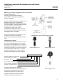
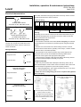
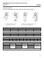
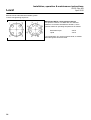
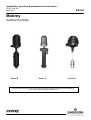
Installation, operation & maintenance instructions
IP152, Rev AD
April 2012
Level
Mobrey
Vertical Controls
Series B
Series X
Series D
For instructions specific to ATEX approved flameproof models in hazardous area installations,
refer to accompanying leaflet IP152/SI Exd
www.emersonprocess.com
Installation, operation & maintenance instructions
Level
2
IP152, Rev AD
April 2012
Installation, operation & maintenance instructions
IP152, Rev AD
April 2012
Level
Mobrey vertical magnetic level controls
Principle of Operation
Switching is achieved with the Mobrey
“three-magnet” system, giving snap-action
“latch-on” switching.
Vertical movement of the primary magnet A in a
glandless pressure tube simultaneously
actuates magnets B & C to switch the contacts.
The “three-magnet” system enables the primary
magnet to pass on and actuate switch
mechanisms at other levels. Switch
mechanisms already actuated can not re-set
until the return of the primary magnet actuates
the magnet system once again.
The primary magnet is moved vertically in the
pressure tube by a float or displacer
mechanism which rises and falls with the liquid
level.
Identifying your control
This manual covers the three series of controls:
B, X and D as shown opposite. Your control
has a part number stamped on the nameplate,
an example of which is shown below. From this
number you can identify your control and turn to
the relevant pages in this manual. As switch
mechanisms are common to all three series,
electrical characteristics are given on page 4.
Diagrammatic detail of three magnet system
Series B pages 5 & 6
Series X pages 5 & 6
XC 13F S7A 1 D8/112
Series & material of construction
Float or displacer module
Enclosure module
No. of switch mechanisms
Type of switch mechanisms
Chamber or flange module
Controls manufactured to customer’s
requirements outside of our standard range will
be numbered 707★★/★★★/★ and may be
identified according to the pictures above.
Series D pages 7 & 8
Displacer operated controls are covered in
Installation Instruction booklet IP153.
3
Installation, operation & maintenance instructions
IP152, Rev AD
April 2012
Level
Electrical characteristics
4 Contact Type : D4, X4, P4, H4
Each switch mechanism has flying leads which are factory wired to ceramic
terminal blocks fixed in the switch enclosure.
Electrical rating
2x independent SPST
AA make on rise : BB make on fall
8 Contact Type : D8, X8, P8, H8
Type
Temp
wetside
°C
Low
Temp
use
D4, D8
X4, X8
P4, P8
H4, H8
400
250
400
250
Amp.
Amb.
Amb.
-100°C
AC max. values
VA
2000
2000
6
2000
Volts
Amps
440
5
440
10
250
0.25
400
5
Power factor
0.4 mm
AC max. values
Watts
50
50
3.6
50
Volts
Res
amps
Ind
amps
250
5
250
10
250
0.25
250
5
Time constant
40ms max.
0.5
0.5
0.1
0.5
Warning
Double pole double throw
(4x independent SPST)
AA make on rise : BB make on fall
Note: For DPDT operation, installer must
common any one pair of A and B wires in the
terminal block for each of the two ends of the
switch mechanism.
Wiring Examples
Single-switch Control
As high level alarm
As low level alarm
A
A
B
B
A
A
B
B
Alarm ON
A
A
B
B
A
A
B
B
LLA Switch
Important wiring notes
1. To minimize the electrical shock hazard, before energizing it is essential
that the equipment is connected to a protective ground using the terminals
supplied.
2. Switches must not be used for the direct starting of motors. Contacts
should be wired in series with the operating coils of relays, contactor starters
or solenoid valves, and fused separately.
3. The temperature of the switch enclosure may at times approach the
temperature of the process and suitable heat resisting cables should
therefore be used, together with appropriate cable glands.
4. A sufficient length of flexible cable should be fitted to allow easy removal
of the switch head and displacer assembly at any time.
Flameproof models
Alarm ON
Two-Switch Control
Combined Pump Control
And Low Level Alarm
Pump Control Switch
Gold plating on the contacts of the P4 and P8 switch mechanisms may be
permanently damaged if the mechanisms are used to switch circuits with
values greater than those shown above.
5. Cable entry must be fitted with a flameproof cable entry device, with or
without thread adaptor, and should be used in accordance with a local Code
of Practice subject to agreement by the local Inspecting Authority.
6. U.L. Approved Applications: Use copper conductors 60°/75°C: 140°/167°F
ONLY. Torque terminals to 6kg/cm: 7lb/in.
Pump ON
7. Ensure the cover locking safety grub screw is replaced and tightened
before energizing.
Two switch pump control circuit using
‘holding’ relay for starters without
auxiliary contacts.
Alarm ON
Two-switch Control
High and Low Level Alarm
4
HLA Switch
A
A
B
B
LLA Switch
A
A
B
B
Alarm ON
Alarm ON
Two switch pump control circuit using
auxiliary contacts on starter.
Note diagram shows starter fitted with
250V coil for 3-phase 3-wire supply
connect coil terminal N to line 1 and fit
440V coil.
Installation, operation & maintenance instructions
IP152, Rev AD
April 2012
Level
P4, P8, H4, H8 Switch Mechanisms - Simple Apparatus
These Switch Mechanisms in a standard switch housing are classified as “Simple Apparatus” when used in Intrinsically Safe
circuits. They comply with the requirements of EN60079-0, General Requirements and EN60079-11, clause 5.7 ‘Simple
Apparatus’ and are not considered as a potential source of ignition for an explosive atmosphere.
They do not fulfill the definition of equipment in Article 1 (3) of Directive 94/9/EC (Equipment Explosive Atmospheres (ATEX)
and are therefore outside the scope this Directive and do not have a Declaration of Conformity or CE mark related to this
Directive.
When used as “Simple apparatus” within a hazardous atmosphere the following should be noted:
1. The product should be installed by suitably trained personnel, in accordance with the applicable code of practice.
2. As the product has no source of internal heating, the temperature classification is dependent on the ambient air temperature
and the temperature of the process vessel to which it is attached.
3. Materials of construction: Refer to product catalogue or customer drawing for actual material of level switch concerned.
Housing and Cover:
Carbon Steel, or Stainless Steel 316 type, or Aluminium Alloy LM25 or LM24 or
B85 grd 360, or Cast Iron grd 250, or Gunmetal LG2
Pressure Tube & Union:
Stainless Steel types 316, 321 or 304, or Carbon Steel 220M07, or Alloy NA18,
or Alloy C-276 (UNS N10276) or Alloy 625 UNS N06625, or Alloy 825 UNS N08825
If the equipment is likely to come into contact with aggressive substances, it is the responsibility of the user to take suitable
precautions that prevent it from being adversely affected, thus ensuring that the type of protection is not compromised.
Aggressive substances: e.g. acidic liquids or gases that may attack metals or solvents that may affect polymeric materials.
Suitable precautions: e.g. regular checks as part of routine inspections or establishing from the material’s data sheet that it
is resistant to specific chemicals.
Note: The metallic alloy used for the enclosure material may be at the accessible surface of this equipment; in the event of
rare accidents, ignition sources due to impact and friction sparks could occur. This shall be considered when the switch is
being installed in locations that specifically require group II, category 1G equipment.
4. It is the responsibility of the user to ensure:
a. The joint requirements between the switch housing and vessel are compatible with the process media.
b. The joint tightness is correct for the joint material used.
c. That suitable temperature rated cable is used. Note: The cable entry temperature may exceed 70°C
d. The float is protected from impact or friction, or static electrical build-up from fast flowing non-conductive
fluids, that could generate an ignition source.
5
Installation, operation & maintenance instructions
IP152, Rev AD
April 2012
Level
Series B & X
Installation Instructions
When installing, using or maintaining external chambers supplied compliant with the Pressure Equipment Directive,
refer also to the Safety Information (leaflet No. IP152/SI) supplied with the product for further details.
Installation shall be carried out by suitably trained personnel in accordance with applicable codes of practice.
1. Remove all sealing tapes, tie strings and packing from the control prior to installation.
2. Mount the control on the inlet and outlet connections, ensuring that the central line axis of the control is vertical to the
eye. Use suitable process connection gaskets and seals as dictated by the application.
3. Check bolt torques on process and switch head flange bolts are in accordance with torques shown on page 12.
Note
i) A 50mm weld bead or label on the chamber indicates the highest operating level of the control. Switch point adjustment
of 94mm is provided on multi-switch models only and is measured down from this level.
ii) Allow at least 200mm above the control for removal of cover.
3. Remove switch head cover to reveal terminal block(s) to which electrical connections are to be made.
Flameproof models: Locate and slacken off M5 socket head safety grub screw on side of cover adjacent to base joint.
Place a bar across the top of the cover, locating in the castellations. The cover can now be unscrewed from the base
using the bar as a lever.
Weatherproof models: The cover can be removed by unscrewing the single hexagon nut at the crown of the cover.
4. Connect electrical wiring via the conduit entries using a suitable cable gland. Note that the base of the enclosure is
rotatable on the pressure tube to allow the most convenient orientation of the conduit entry.
Refer to wiring notes on page 4.
On models with flameproof enclosures type ★7★ the switch mechanism may be raised on the pressure tube to ease access
to the terminal block. Ensure that the switch mechanism is re-positioned to its lowest position (i.e. sitting on the limit tube
around the pressure tube) after wiring.
5. Switch point adjustments may now be made if necessary. See below.
6. The lugs of the tab washer directly underneath the base must now be bent over to locate on the most appropriate flats of
the hexagon union. This prevents further rotation of the switch head, and is particularly important as it will prevent
rotation when the cover is removed or re-fitted.
7. Check the cover seals are present and in good condition, and then replace the cover.
(i) Before energizing flameproof / Type ★7★ models, ensure the cover locking safety grub screw is replaced and
tightened. Do not energize if the cover locking safety grub screw is missing.
(ii) Before energizing weatherproof / Type ★4★ models, ensure the weatherproofing fibre sealing washer at the crown
nut is in place.
Switching Point Adjustment
Each switch mechanism is mounted on a bracket, which is secured on the pressure tube by a locking screw and lock nut.
These can be loosened, allowing the bracket to be adjusted up or down as required. Always ensure that the small pressure
plate between the locking screw and the pressure tube is in place before
re-tightening the locking screw nut.
Important note: Switches cannot be adjusted outside of the range set by the stops on the pressure tube. Displacer operated
control type ★★17D are single switch models with the switching point factory set.
There is no site adjustment.
Enclosure Type
Max. No. Switches
Sw. Adjustment ‘B’ mm
Max. Wet
switching differential
Max. No. Switches
Sw. Adjustment ‘B’ mm
Min. Sw Crs ‘B’ mm
Max. Sw Crs ‘B’ mm
Max. Wet switching differential
6
R7A
R7I
R4N
S7A
S7I
S4N
Switch Mechanism Type
D4, P4, X4
H4
D8, P8, X8, H8
1
1
1
7
7
7
Type 11F, 12F, 13F, 14F : 20mm
Type 17D : See table above (D-C)
4
4
2
94
94
94
94
94
94
7
0
56
Type 11F, 12F, 13F, 14F : 120mm
Installation, operation & maintenance instructions
IP152, Rev AD
April 2012
Level
Operating Level Data
Models Type No. B 11F, B 12F, B 13F, B 14F, B 17D, X 11F, X 12F, X 13F, X 14F, X 17D
C = Highest Operating Liquid Level
D (Single Switch) = Reset Level
D (Multi-Switch) = Lowest Operating Liquid Level
D-C = Wet Switching Differential (Max)
Operating Levels : Single switch models
Min Operating S.G.
11F : 0.80
Dimension C
50
Dimension D
70
12F : 0.75
50
70
13F : 0.65
50
70
14F : 0.54
50
70
Operating Levels : Multi-switch models
Min Operating S.G.
11F : 0.80
Dimension C
50
Dimension D
170
12F : 0.75
50
170
13F : 0.65
50
170
14F : 0.54
50
170
Operating Levels : Type 17D float in any chamber : Single switch only
Min Operating S.G.
0.4
0.5
0.6
0.7
0.8
Dimension C
65
73
82
91
100
Dimension D
118
122
127
132
137
0.9
109
141
1.0
118
147
1.1
127
152
1.2
136
156
Dimensional Data : Enclosures
Type
Duty
Height G
Conduit Thread
Switch Adjustment Weatherproof Rating
R7A, R71
190
10
IP66 to IEC 60529
Flameproof
1” NPT
(NEMA 4)
S7A, S71
300
94
R4N
170
10
IP66 to IEC 60529
S4N
Weatherproof
275
1” NPT
94
(NEMA 4)
L4N
375
194
Enclosures for use with 8 contact switch mechanisms have both conduit entries threaded, whilst those for use with 4 contact
switch mechanisms have only one entry. See Note 4, page 4.
7
Installation, operation & maintenance instructions
IP152, Rev AD
April 2012
Level
Series D
Installation Instructions
Installation shall be carried out by suitably trained personnel in accordance with applicable codes of practice.
1. Remove all sealing tapes, tie strings and protective packings from
the control prior to installation. If float rod length needs adjusting to
allow a higher operating level, refer to adjustment notes on page 8.
Note: Careful handling is required at all times to ensure float and float
rod are not damaged or bent.
If a control is fitted with a longer than standard rod (i.e. dimension H is
greater than that shown in the adjoining table) or the liquid is subject to
excessive turbulence or agitation, then a stilling tube should be fitted.
2. If control has been ordered without a mounting flange, the float unit
must be removed from the control before the switch head can be
mounted on the vessel via the 1”NPT threaded boss provided. This is
achieved by locating the Stop Assembly at the base of the 1”NPT
threaded boss and easing the spring clip, allowing the entire float
assembly to be removed.
3. Mount the switch head on the vessel using the flange (if provided) or
the 1”NPT threaded boss ensuring that the centre line axis is vertical to
the eye. If the threaded boss is used, ensure a pressure tight seal is
formed between it and the vessel. Use only the hexagonal boss to
tighten the 1”NPT thread into the mounting boss or flange. Torque
flange bolts in accordance with torques shown on page 12.
4. Ensure that magnet is free from swarf and debris before re-fitting to
switch head. Locate the two ends of the spring clip in the two cross
holes in the base of the pressure tube ensuring that float assembly is
free to move vertically and is securely retained by the Stop Assembly.
5. Remove switch head cover to reveal terminal block(s) to which
electrical connections are to be made:Flameproof models: Locate and slacken off M5 socket head safety
grub screw on side of cover adjacent to base joint. Place a bar across
the top of the cover, locating in the castellations. The cover can now be
unscrewed from the base using the bar as a lever.
Weatherproof models: The cover can be removed by unscrewing the
single hexagon nut at the crown of the cover.
6. Connect electrical wiring via the conduit entries using a suitable
cable gland. Note that the base of the enclosure is rotatable on the
pressure tube to allow the most convenient orientation of the conduit
entry.
Refer to wiring notes on page 4.
Floats for 3” NB mounting : 11F
G
H*
H + 35
150
Ø67
*Float rod may be shortened to suit
11F
H dimension
Switch
Wet switching
adjustment
differential
315
none
20mm
315
94mm
114mm max.
when used
Min
Max
with :
H
H
R4N R7A R71
155
S4N S7A S71
155
L4N
Floats for 4” BB mounting : 12F, 13F, 14F
G
H*
H + 35
160
3F . 4F Ø88
2F Ø90
*Float rod may be shortened to suit
H dimension
when used
12F,13F,14F
Switch
Wet switching
Min
adjustment
differential
20mm
Max
with :
H
H
R4N R7A R71
155
415
none
S4N S7A S71
155
415
94mm
114mm max.
L4N
155
415
194mm
214mm max.
Operating Levels
Lowest operating levels
Highest operating levels
: see adjustment notes
H + 35
(H + 35) – (B + 20) where B is
the max. switch adjustment
from table on page 8.
On models with flameproof enclosures type ★7★ the switch mechanism may be raised on the pressure tube to ease access to
the Terminal Block. Ensure that the switch mechanism is re-positioned to its lowest position (i.e. sitting on the limit tube around
the pressure tube) after wiring.
7. Switch point adjustment may now be made if necessary. See page 8.
8. The lugs of the tab washer directly underneath the base must now be bent over to locate on the most appropriate flats of the
hexagon union. This prevents further rotation of the switch head, and is particularly important as it will prevent rotation when
the cover is removed or re-fitted.
9. Check the cover seals are present and in good condition, and then replace the cover.
(i) Before energizing flameproof / Type ★7★ models, ensure the cover locking safety grub screw is replaced and
tightened. Do not energize if the cover locking safety grub screw is missing.
(ii) Before energizing weatherproof / Type ★4★ models, ensure the weatherproofing fibre sealing washer at the crown nut
is in place.
8
Installation, operation & maintenance instructions
IP152, Rev AD
April 2012
Level
Enclosure type
Switching Point Adjustment
Switch Mechanism Type
D4, P4, X4
Each switch mechanism is mounted on a
Max. No. Switches
bracket, which is secured on the pressure
tube by a locking screw and lock nut.
Sw. Adjustment ‘B’
Max. Wet switching
differential
These can be loosened, allowing the bracket
to be adjusted up or down as required. Always
Max. No. Switches
ensure that the small pressure plate between
the locking screw and pressure tube is in
place before re-tightening the locking screw
nut.
Important note: Switches can not be
R7I
D8, P8, X8, H8
1
1
7
7
7
7
R4N
Type 11F, 12F, 13F, 14F : 20mm
4
4
2
S7A
94
94
94
Max. Sw Crs ‘B’
S7I
94
94
94
Min. Sw Crs ‘B’
Max. Wet switching
differential
S4N
7
0
56
Type 11F, 12F, 13F, 14F : 114mm
Max. No. Switches
6
6
3
Sw. Adjustment ‘B’
194
194
194
194
194
194
0
56
L4N
Min. Sw Crs ‘B’
Max. Wet Switching
differential
on the pressure tube. Displacer operation
controls are covered in Installation Instruction
H4
Sw. Adjustment ‘B’
Max. Sw Crs ‘B’
adjusted outside of the range set by the stops
R7A
7
Type 11F, 12F, 13F, 14F : 214mm
booklet IP153
Float Rod Length Adjustment
The highest operating level given by the float rod as supplied can be made higher (i.e. nearer the mounting point) by shortening
the float rod on site, as follows:
Remove float unit from control by locating the Stop Assembly in the base of the 1”NPT threaded boss and easing the spring clip
out of the two locating holes in the pressure tube. The rod and the magnet assembly can now be withdrawn from the pressure
tube. Undo the hexagonal float adaptor to remove the float from the rod, and slide the adaptor up the rod. Hacksaw the stainless
steel rod to the required length according to the diagram below, and then re-clench the rod end in a vice as shown. Re-fit the
float, ensuring the spring washer is used between float and adaptor.
Re-fit the float unit to the switch head, ensuring that the magnet is free from swarf and debris. Locate the two ends of the spring
clip in the two cross holes in the pressure tube; ensuring that the rod and magnet assembly are free to move vertically in the
pressure tube and that it is securely retained by the Stop Assembly.
Magnet
Rod
3.0 min
Minimum lengths with switch heads to
give highest operating level of 190mm
R7A R71 R4N : 316
S7A S71 S4N : 421
L4N : 521
Cut &
re-clench
3.5 min
9
Installation, operation & maintenance instructions
Level
IP152, Rev AD
April 2012
Maintenance of the Mobrey vertical level controls
Inspection and maintenance shall be carried out by suitably trained personnel in accordance with applicable codes of
practice.
Series B-Vertical Integral Type
This type of control is of the ‘sealed chamber’ type and the float or displacer mechanism cannot be removed.
However, the switch mechanisms and switch head should be visually checked periodically.
1. Isolate electrical circuits to control and disconnect wiring as necessary.
2. Remove the switch head cover and examine the switch mechanism body for any damage. Ensure that wiring is in good
order and that all the screws are tight. Dismantling of switch unit is not recommended and replacement of the
complete switch unit will be found to offer the quickest and most economical solution in event of faulty operation.
See page 10.
3. Check sealing gasket / “O” ring and replace if necessary.
4. Check the cover seals are present and in good condition, and then replace the cover.
(i) Before energizing flameproof / Type ★7★ models, ensure the cover locking safety grub screw is replaced and
tightened. Do not energize if the cover locking safety grub screw is missing.
(ii) Before energizing weatherproof / Type ★4★ models, ensure the weatherproofing fibre sealing washer at the crown nut
is in place.
Series X - Vertical Flanged Type
This type of control is flanged between the switch head and chamber such that the float may be withdrawn and removed from
the chamber for inspection.
1. Isolate electrical circuits to control and disconnect wiring as necessary.
2.
Isolate the chamber from the pressure vessel by closing the isolation valves, and open the valve of the drain connection.
3.
Remove nuts holding control to chamber, carefully withdraw switch head and float assembly, taking care not to bend the
float rod.
4. Separate float assembly from switch head by removing stop clip.
5. Inspect the chamber and remove any deposits.
6. Check float, float rod and magnet for excessive wear, clean and replace as necessary.
7. Fit replacement joint and reassemble, taking care not to bend the float rod. Firmly tighten nuts on top flange, using bolt
torque values given in tables on page 12.
8. Remove the switch head cover and examine the switch mechanism body for any damage. Ensure that wiring is in good
order and that all the screws are tight. Dismantling of switch units is not recommended and replacement of the
complete switch unit will be found to offer the quickest and most economical solution in event of faulty operation.
See page 10.
9. Check sealing gaskets / “O” ring and replace of necessary.
10. Check the cover seals are present and in good condition, and then replace the cover.
(i) Before energizing flameproof / Type ★7★ models, ensure the cover locking safety grub screw is replaced and
tightened. Do not energize if the cover locking safety grub screw is missing.
(ii) Before energizing weatherproof / Type ★4★ models, ensure the weatherproofing fibre sealing washer at the crown nut
is in place.
11. Close drain valve connection, open isolating valves and check that the control is operating at the correct levels.
Series D - Direct Mounted Type
This type of control is mounted directly onto the process vessel, or may be mounted in a chamber.
1. Isolate electrical circuits to control and disconnect wiring as necessary.
2. Ensure the vessel is vented to atmosphere, or isolate any chamber from the vessel by closing the isolating valves, and open
the valve of the drain connection.
3. Remove nuts holding control to chamber or vessel. Carefully withdraw switch head and float assembly, taking care not to
bend the float rod.
4. Separate float assembly from switch head by removing stop clip.
10
Installation, operation & maintenance instructions
IP152, Rev AD
April 2012
Level
5. Inspect the chamber or stilling tube and remove any deposits.
6. Check float, float rod, and magnet for excessive wear, clean and replace as necessary.
7. Fit replacement joint and reassemble, taking care not to bend the float rod. Use bolt torque values given in tables on page 12.
8. Remove the switch head cover and examine the switch mechanism body for any damage. Ensure that the wiring is in good
order and that all screws are tight. Dismantling of switch units is not recommended and replacement of the complete
switch unit will be found to offer the quickest and most economical solution in event of faulty operation.
See page 10.
9. Check sealing gaskets / “O” ring and replace if necessary.
10. Check the cover seals are present and in good condition, and then replace the cover.
(i) Before energizing flameproof / Type ★7★ models, ensure the cover locking safety grub screw is replaced and
tightened. Do not energize if the cover locking safety grub screw is missing.
(ii) Before energizing weatherproof / Type ★4★ models, ensure the weatherproofing fibre sealing washer at the crown nut
is in place.
11. If the control is mounted into a chamber, close drain valve connection, open isolating valves and check that the control is
operating at the correct levels.
11
Installation, operation & maintenance instructions
IP152, Rev AD
April 2012
Level
When fitting a spare or replacement switch mechanism
IMPORTANT NOTE
If a spare switch mechanism is fitted at any time, it is important that the magnet system is left in the correct mode.
After installation of a replacement switch mechanism, always check that the B-B contacts are made, assuming the chamber is
empty of liquid. If the chamber is full of liquid, then A-A contacts should be checked to ensure they are made.
If it is found that a switch mechanism is not in the correct mode, then the liquid level in the chamber should be raised such that
the primary float magnet passes through the switching point. Lowering the liquid level will then cause the float magnet to fall
back through the switching point, thus leaving the switch mechanism in the correct operating mode (For a control operating as
low level alarm, the liquid level should be first lowered then raised back to ensure the switch mechanism is in the correct
operating mode).
Full fitting instructions are supplied with each spare or replacement switch mechanism.
1
Switch mechanism kit
Series B,X,D
Series B,X,D
comprising
Weatherproof
Weatherproof
Switch mechanism and fittings
4 Contact 5 Amp
D4
SK178
SK178
4 Contact plated
P4
SK179
SK179
4 Contact 10 Amp
X4
SK180
SK180
4 Contact sealed
H4
SK181
SK181
8 Contact 5 Amp
D8
SK182
SK182
8 Contact plated
P8
SK183
SK183
8 Contact 10 Amp
X8
SK184
SK184
8 Contact sealed
H8
SK185
SK185
SK190
SK191
Sales Kit
Series B
Float unit only
Series X
Series D
SK192
SK192
N/A
SK193
SK193
13F
Sealed
SK194
SK194
14F
Chamber
SK195
SK195
SK196
SK196
11F
12F
1
17D
Series B
2
Complete float
assembly, comprising
float unit and
rod and magnet
assembly
Series X
Contact factory with
12F
full model number and
14F
17D
N/A
Sealed
Chamber
XC13F S7A 1 D8/112
Float
3
complete assembly
can be supplied
7 = Flameproof
4 = Weatherproof
12
1
Series D
11F
13F
Mechanism
Series
1
2
1
2
Installation, operation & maintenance instructions
IP152, Rev AD
April 2012
Level
Bolting Torques
Information in this section is to the best of our knowledge correct. Since conditions of use are beyond our control users must
satisfy themselves that bolt/torques are suitable for the flange/process/conditions of the applications.
Bolting Torque details: High tensile steel bolts
IMPORTANT:-
Bolt torques for SPIRAL WOUND gaskets with a
For use with high tensile steel bolts only
compression stop : high tensile steel bolts only.
Rosemount Measurement Limited use high tensile bolts/
studs as standard for pressure vessel flange applications
Bolt Size
Nm
Lbf. ft
which allows use to full switch rating. The following
5/8”
122
90
recommended torques assume the use of high tensile
3/4”
203
150
7/6”
325
240
1”
499
368
1 – 1/8”
722
533
1 – ¼”
101
750
bolts. If ordinary carbon steel bolts are fitted see below for
bolt tightening torques.
Min. Torques in Nm (lbf. Ft) Max. torque = Min + 10%
Flange
Class 150
Class 130
3”
230
(169)
125
(169)
4”
190
(140)
220
(140)
6”
352
(260)
Flange
Gasket compression for joints without compression
stops : high tensile steel bolts only.
Initial gasket
thickness
PN16
PN40
DN65
185
(136)
80
(59)
DN80
125
(92)
95
(70)
DN100
125
(92)
150
(111)
DN125
195
(144)
225
(166)
DN150
255
(188)
280
(206)
MOBREY A
34 (25)
MOBREY G
26 (20)
Compressed
thickness
Compression
1.6mm
1.3/1.4mm
0.2/0.3mm
2.5mm
1.9/2.0mm
0.5/0.6mm
3.2mm
2.3/2.5mm
0.7/0.9mm
4.4mm
3.2/2.5mm
1.0/1.2mm
6.4mm
4.6/5.1mm
1.3/1.8mm
Bolting torque details: Carbon steel bolts only
Min. torques in Nm (lbf. Ft) Max. Torque – Min + 10%
Flange
Class 150
Class 300
3”
54
(40)
95
(70)
4”
54
(40)
95
(70)
6”
95
(70)
Flange
DN65
PN16
58
(43)
PN40
58
(43)
DN80
58
(43)
58
(43)
DN100
58
(43)
113
(83)
DN125
58
(43)
194
(143)
DN150
113
(83)
194
(143)
MOBREY A
20 (15)
MOBREY G
20 (15)
IMPORTANT:For use with carbon steel bolts only
If ordinary carbon steel or similar lower quality bolts
are used the torques recommended are as shown
on the left.
The gasket sealing force created by the application
of these torques is not sufficient to withstand full
flange pressure rating. To achieve full rating, use
high tensile steel bolts as above.
If in doubt about your bolt/sealing application
consult your engineering department or gasket
manufacturer.
13
Installation, operation & maintenance instructions
IP152, Rev AD
April 2012
Level
Bolts should be lubricated with suitable grease.
Correct bolt tightening sequence:-
IMPORTANT NOTE: Sheet gasket materials
This product contains or is fitted with non asbestos
gaskets in accordance with BS7531 Grade X, which
specifies maximum operating temperatures as follows:
Gas/steam/vapor
Liquid
250°C
400°C
If your application is in excess of these limits, a suitable
alternative gasket should be fitted.
14
Installation, operation & maintenance instructions
IP152, Rev AD
April 2012
Level
15
Installation, operation & maintenance instructions
IP152, Rev AD
April 2012
Level
The Emerson logo is a trade mark and service mark of Emerson Electric Co.
Rosemount is a registered trademark of Rosemount Inc.
Mobrey is a registered trademark of Rosemount Measurement Ltd.
All other marks are the property of their respective owners
We reserve the right to modify or improve the designs or specifications of product and services at any time without notice.
© 2012 Rosemount Measurement Ltd. All rights reserved.
International:
Emerson Process Management
Rosemount Measurement Ltd.
158 Edinburgh Avenue
Slough, Berks, SL1 4UE, UK
Tel: +44 (0) 1753 756600
Fax: +44 (0) 1753 823589
www.emersonprocess.com
Americas:
Emerson Process Management
Rosemount Inc.
8200 Market Boulevard
Chanhassen, MN 55317, USA
Tel: (USA) 1 800 999 9307
Tel: (International) +1 952 906 8888
Fax: +1 952 906 8889