1
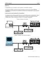
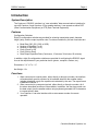
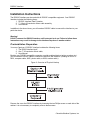
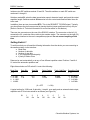
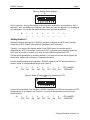
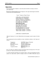
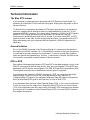
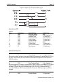
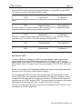
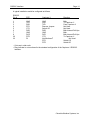
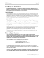
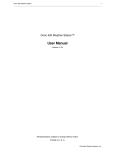
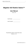
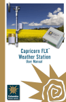
Capricorn II™
RS232C Interface
User Manual
Version 3.0
Copyright 1984, 1988, 1990, 2003
Columbia Weather Systems, Inc.
All Rights Reserved
www.columbiaweather.com
Proprietary Notice: Capricorn II™ is a trademark of Columbia Weather Systems, Inc. The information and drawings contained herein
are the sole property of Columbia Weather Systems, Inc. Use of this publication is reserved exclusively for customers of Columbia
Weather Systems, Inc. and their personnel. Reproduction of this material is forbidden without the express written consent of
Columbia Weather Systems, Inc.
All specifications are subject to change without notice.
Printed in USA
RS232C Interface
Page 2
Welcome!
Congratulations on your selection of the Capricorn II with RS232C Interface.
The Capricorn RS232C Interface has been designed to provide a truly universal RS232Ccompatible device that gives you the flexibility to interface the weather station to your computer
or peripheral.
Please read the entire manual prior to installation.
The diagrams below show two typical Capricorn II and Interface system configurations. Figure 1
illustrates the Capricorn II/RS232C connected directly to a printer for automatically printed
weather reports. Figure 2 illustrates a Capricorn II to computer configuration.
Figure 1: Capricorn II to Printer
Figure 2: Capricorn II to Personal Computer
Columbia Weather Systems, Inc.
RS232C Interface
Page 3
Table of Contents
INTRODUCTION........................................................................................................................................... 4
SYSTEM DESCRIPTION ................................................................................................................................. 4
FEATURES................................................................................................................................................... 4
FUNCTIONS ................................................................................................................................................. 4
INSTALLATION INSTRUCTIONS................................................................................................................ 5
PRE-INSTALLATION PREPARATION ................................................................................................................ 5
SETTING SWITCH 1...................................................................................................................................... 6
SETTING SWITCH 2...................................................................................................................................... 7
CONNECTING THE INTERFACE ...................................................................................................................... 8
OPERATION................................................................................................................................................. 9
TECHNICAL INFORMATION ..................................................................................................................... 11
THE BLUE RTS JUMPER ............................................................................................................................ 11
GROUND ISOLATION................................................................................................................................... 11
DTE OR DCE............................................................................................................................................ 11
USER SUPPORT INFORMATION ............................................................................................................. 15
LIMITED WARRANTY................................................................................................................................... 15
RETURN FOR REPAIR PROCEDURE ............................................................................................................. 15
Columbia Weather Systems, Inc.
RS232C Interface
Page 4
Introduction
System Description
The Capricorn II RS232C Interface is a “user-selectable” data communications interface for
use with Capricorn II and Capricorn II Plus weather stations. It can operate as either DCE
(Data Communication Equipment) or DTE (Data Terminal Equipment).
Features
Configuration Switches:
Eight (8) configuration switches are provided for selecting transmission peed, character
length, parity, and the output repetition rate. Functions controlled by this set of switches are:
♦
♦
♦
♦
♦
♦
Baud Rate (300, 600, 1200, or 9600)
Number of Data Bits (7 or 8)
Number of Stop Bits (1 or 2)
Parity (Check or Off)
Parity (Odd or Even)
Data Output Repetition Rate (Continuous, 15 minutes, 30 minutes, 60 minutes)
In addition, eight (8) configuration switches are provided for configuring the RS232C signal
lines to the requirements of your particular device (printer, computer, modem, etc.).
Dimensions: 3 ½” x 5” x 1 ½”
Net Weight: 1 lb.
Functions
1. When connected to a serial printer, either directly or through a modem, the Interface
will automatically provide a printout of all available data from the weather station
(whether displayed or not) at a repetition rate selected by the user. The report format
is detailed in Section 3.
2. When connected to a computer terminal, either directly or through a modem, all of
the above described functions will be available. In addition, the user has control over
the data output from the weather station using keyboard generated ASCII characters
to request specific data.
3. Your Capricorn II can also interface with an auto-answer modem for remote
operation.
Columbia Weather Systems, Inc.
RS232C Interface
Page 5
Installation Instructions
The RS232C Interface can be used with all RS232C compatible equipment. Your RS232C
Interface includes the following items;
1. RS232C Interface Data Formatter
2. 7” (18cm) 20-conductor ribbon cable assembly
3. User Manual
In addition to the above items, you will need an RS232C cable to connect the Interface to your
particular device.
Warning!
DO NOT connect the RS232C Interface until instructed to do so. Failure to follow these
instructions may result in damage to the Interface/Capricorn II weather station.
Pre-Installation Preparation
Your new Capricorn II RS232C Interface includes the following items:
1. The RS232 Interface itself;
2. One 7” 20-conductor ribbon cable;
3. User Manual
Besides your RS232C-compatible computer or serial peripheral device (printer, modem, etc.),
you will need an RS232C cable to connect the device to the Interface. (Catalog No. 8235 or
8236, computer cable; 8305, printer cable; or 8234, modem cable.)
Figure 3: Overview of Physical Hookup
Remove the cover the RS232C Interface by loosening the two Phillips screw on each side of the
cabinet. It is not necessary to completely remove these screws.
Columbia Weather Systems, Inc.
RS232C Interface
Page 6
Inside are two DIP switches marked S1 and S2. The slide switches on each DIP switch are
numbered 1 through 8.
Switches marked S1 select the data transmission speed, character length, parity and the output
repetition length. Switches marked S2 determine how the control and communication lines are
to be used.
In addition, there are two pins marked RTS. This is the REQUEST TO SEND signal. Typically,
you should leave the pins unconnected by leaving the blue jumper positioned on only one pin.
(Refer to Section 4: Technical Information for more information on this feature.)
There are two connectors on the rear of the RS232C Interface. The connector on the left (J1)
connects the 20 –conductor ribbon cable to the weather station. The connector on the right (J2)
connects the Interface to the user’s compatible equipment. Do not connect anything at this
time.
Setting Switch 1
To set this switch you will need the following information from the device you are connecting to
the weather station via the Interface:
♦ Baud Rate
♦ Number of data bits
♦ Number of stop bits
♦ If you equipment checks parity
♦ If parity is Odd or Even
Data can be sent automatically or at any of four different repetition rates. Positions 7 and 8 of
S1 control the automatic repetition rate.
Eight slide switches on DIP switch S1 control the following:
Baud Rate
1 2
Data Bits
3
Stop Bits
4
Parity Enable
5
0
1
0
1
0=7
1 =8
0=1
1=2
0=No
1=Yes
0= 300
0= 600
1= 1200
1=9600
(0 = OFF
Parity Odd/Even
6
0=Odd
1=Even
Repetition Rate
7 8
0
1
0
1
0=Contin.
0=15 Min.
1=30 Min.
1=60 Min.
1 = ON)
A typical setting for 1200 baud, 8 data bits, 1 stop bit, even parity and an automatic data output,
repetition rate of 30 minutes would be as follows (see Figure 4):
S1
1
Off
2
On
3
On
4
Off
5
On
6
On
7
Off
8
On
Columbia Weather Systems, Inc.
RS232C Interface
Page 7
Figure 4: Sample Switch Settings
S1
Set S1 positions 1 through 6 according to the information obtained for your equipment. Set S1
positions 7 and 7 according to the frequency with which you want the Capricorn II to sent data to
your equipment. You can use the space below to record your switch positions.
S1
1
___
2
___
3
___
4
___
5
___
6
___
7
___
8
___
Setting Switch 2
Determine whether the Capricorn II RS232C Interface will appear as a DTE (Data Terminal
Equipment) or DCE (Data Communications Equipment) when connected.
Typically, if you connect the weather station to the RS232 port of a computer which is
configured as a DTE, the Interface is set up as a DCE. If you connect the weather station to a
DCE, such as a printer or modem, you must set up the RS232 Interface as a DTE.
Use the following examples to set these switches. If you need to know the actual signal to pin
connections, please refer to Section 4: Technical Information.
Use the following settings if the Capricorn II RS232C Interface is a DTE and connected to a
modem, printer, or other peripheral device (see Figure 5):
S2
1
OFF
2
ON
3
ON
4
OFF
5
ON
6
OFF
7
OFF
8
ON
RTS JUMPER
REMOVED
Figure 5: Switch 2 Setting Capricorn Interface as a DTE
S2
Use the following setting if the Capricorn II RS232C Interface is a DCE and connected to a DTE
configured port on a computer (see Figure 6): You can use the space below to record your
switch positions.
S2
1
OFF
2
OFF
3
ON
4
OFF
5
OFF
6
ON
7
ON
8
OFF
RTS JUMPER
REMOVED
Columbia Weather Systems, Inc.
RS232C Interface
Page 8
Figure 6: Switch 2 Setting Capricorn Interface as DCE
S2
S2
1
___
2
___
3
___
4
___
5
___
6
___
7
___
8
___
RTS
___
Connecting the Interface
Remove power from both the Capricorn II weather station and your equipment before
connecting or disconnecting the cables. Unless you have the “Memory Keep Alive Battery”
connected to the back of the Capricorn II, the memory will be lost each time the power is
removed.
Replace the Interface cover and gently tighten the four side screws.
Connect the Interface to the Capricorn II console by plugging in the 7” cable supplied with
the Interface. Plug either end into the 20-pin connector on the LEFT side of the Interface
back panel. Plug the other end into the blue connector on the back of the Capricorn II
console labeled “Connect only to Model No. 8232 RS232C Interface Accessory.” The
Interface can then be place on top of the Capricorn II console.
Connect the Interface to the computer or peripheral device with a user-supplied RS232C 8
to 25-conductor cable using the DB25 connector on the RIGHT side of the Interface back
panel.
The S1 settings can be changed with power on and cable connected without causing any
damage. The change takes effect immediately. However, it is recommended that power be
removed from the Capricorn II weather station and your equipment before S2 settings are
changed.
Columbia Weather Systems, Inc.
RS232C Interface
Page 9
Operation
Once the initial setup is complete, no user intervention should be necessary to collect or
print weather data.
Based on the selected repetition rate, the Capricorn II will output data through the Interface
to your device in the following manner:
Figure 7: Capricorn II Report Format
CAPRICORN II WEATHER REPORT
INSIDE TEMP XXX.X. DEGREES F
OUTSIDE TEMP XXX.X. DEGREES F
WIND CHILL TEMP XXX.X. DEGREES F
HIGH TEMP XXX.X DEGREES F
LOW TEMP XXX.X. DEGREES F
WIND DIRECTION XXX
WIND SPEED XXX MPH
HIGH WIND SPEED XXX MPH
PEAK WIND GUST XXX MPH
BAROMETER XX.XX INCHES
HIGH BAROMETER XX.X.X INCHES
LOW BAROMETER XX.XX INCHES
WIND ALARM +AUDIBLE+ > XXX MPH
TEMP ALARM +AUDIBLE+ < XXX DEG F
CAPRICORN II CALIBRATE MODE*
*When the Capricorn II is in the Calibrate Mode, this message is output in place of all other
data.
Other measurement units are available, and are controlled by switches on the Capricorn II
console:
Temperature
Wind Speed
Barometric Pressure
Wind Alarm
Temperature Alarm
DEGREES Celsius or Fahrenheit
MPH, KPH, KNOTS
INCHES (HG) MILLIBARS
SILENT, AUDIBLE, OFF
MPH, KPH
SILENT, AUDIBLE, OFF
DEG C or F
Note: The Capricorn II RS232C Interface automatically sends a carriage return <CR> and a
line feed <LF> after each record and after each report.
To request individual parameters for immediate display, type the corresponding character
shown in the table below. (NOTE: Character must be in UPPER CASE.)This may be
Columbia Weather Systems, Inc.
RS232C Interface
Page 10
executed during a wait period between repetitions or after an X-OFF command (Ctrl S) to
stop the data flow as described below. Be sure to send an X-ON command (Ctrl Q) to
resume data flow.
Type:
A
B
C
D
E
F
G
H
I
J
K
L
M
N
For This Parameter:
Inside Temperature
Outside Temperature
Wind Chill Temperature
High Temperature
Low Temperature
Wind Direction
Wind Speed
High Sustained Wind Speed
Peak Wind Gust
Barometric Pressure
High Barometer
Low Barometer
Wind Alarm Setting
Temperature Alarm Setting
The following commands allow further control of the Capricorn II output:
DC3
Stops all data output from the Capricorn II. This option does not inhibit the
(X-OFF) repetition rate selected by the configuration switches. This option may be
(CTRL S) sent from a keyboard to stop the output or may be sent from a printer if the print
buffer is full or the printer is out of paper.
DC1
This option is sent from a computer or printer when data output is to continue
(X-ON)
after an X-0FF command is entered. If X-OFF was sent during an output, the
(CTRL Q) the line being output at the time of the command will hold its value. When X-ON
is sent, the interrupted output line will finish with the old data but the rest of the
report will be completed with current data. If this command is sent during a wait
period, the weather station will output the current values of options A through N
sequentially as if it were a normal output. This does not affect the wait period
before the next output.
DC2
When a DC2 (Ctrl R) is sent from a computer, the memory is reset as if the
(CTRL R) reset switch was used on the Capricorn II console. The feature can be used to
clear the weather station memory from a remote location.
Columbia Weather Systems, Inc.
RS232C Interface
Page 11
Technical Information
The Blue RTS Jumper
If your computer or peripheral device generates and RTS (Request to Send) signal, it is
necessary to connect the RTS pins with the blue jumper. Simply place the jumper so that it
fits over both pins.
To determine if your equipment generates an RTS signal, apply power to your equipment
and use a voltage meter to determine if there is voltage between pin 4 and pin 7 of your
equipment’s RS232C connector. The voltage will be nominally +/-12VDC if an RTS signal is
present. If RTS is being generated by your equipment, you should leave the pins
unconnected by positioning the jumper only on one pin. If you meter read 0VDC, no RTS
signal is present. In that case, connect the pins with the jumper. You should not have RTS
being generated by both your equipment AND the Capricorn II RS232C Interface at the
same time.
Ground Isolation
Pin 1 of the RS232C connector is the Protective Ground. It is connected to the chassis of
the Capricorn II RS232C Interface. Pin 7 of the RS232C connector is the Logic Ground and
is connected to the Logic Ground of the circuit board. To prevent “ground loop” problems,
these two grounds are separated by a 100 ohm, ¼ watt resistor. If desired, clip R9 from the
circuit board to accomplish complete isolation of the two grounds.
DTE or DCE
One method of distinguishing between a DTE and DCE is that data transmits on pin 2 of the
RS232C connector and receives data on pin 3. Also, the control signals RTS and DTR are
generated by a DTE and the control signals CTS, DSR, DCD and RI are generated by DCE.
These signals control the flow of data between the two types of equipment.
If you configure the Capricorn II RS232C Interface as a DTE, the connections should be
straight through. For a DCE, pins 2 and 3 must be reversed so the Capricorn II’s
Transmitted Data (TD) goes to your equipment’s Receive Data (RD) and your equipment’s
Data Terminal Read (DTR) goes to the Capricorn II’s Clear to Send (CTS).
If your equipment does not have a Data Terminal Ready (DTR), or if it is on a pin other than
5 or 20, you must route the Capricorn II’s Request to Sent (RTS) to its own Clear to Send
(CTS). Some equipment uses the control codes X-ON and X-OFF transmitted over the data
lines in place of or in addition to Data Terminal Ready (DTR). Your new RS232C Interface
fully supports this protocol.
Columbia Weather Systems, Inc.
RS232C Interface
Page 12
Figure 8: Diagram of Connections Made by S2
Operation as DTE
RS232C
PIN #
1
2
3
4
5
6
7
8
20
22*
MNEMONIC
GND
TXD
RXD
RTS
CTS
DSR
GND
DCD
DTR
RI
DESCRIPTION
Protective Ground
Transmitted Data
Received Data
Request to Send
Clear to Send
Data Set Ready
Signal Ground
Carrier Detect
Data Terminal Ready
Ring Indicator
DIRECTION
Both
From Capricorn II
To Capricorn II
From Capricorn II
To Capricorn II
To Capricorn II
Both
To Capricorn II
From Capricorn II
To Capricorn II
Operational Sequence:
22
RI
Ring Indicator
To Capricorn II
Says that the phone is ringing. Each active pulse of RI causes a 32 second timer on DTR to
be reset. *Ring Indicator is not monitored in the standard configuration of the Capricorn II
RS232C Interface.
20
DTR
Data Terminal Ready
From Capricorn II
Says that Capricorn II is ready to communicate. If the RI option is not installed, DTR is active
as long as DCD is active and the Capricorn II is ready to communicate. If the RI option is
installed, DTR goes active on the trailing edge of RI. If no DCD is received within 32
seconds, DTR drops. If DCD is received within 32 seconds, DTR stays high until DCD is
dropped.
6
DSR
Data Set Ready
To Capricorn II
Columbia Weather Systems, Inc.
RS232C Interface
Page 13
Says that DCE is ready to accept data from the Capricorn II. Tied to DCD in some DCE’s.
The Capricorn II will not send data until DSR is active.
8
DCD
Carrier Detect
To Capricorn II
Says that DCE has detected a carrier. The Capricorn II will not send data until DCD is
active.
4
RTS
Request to Send
From Capricorn II
When the Capricorn II is ready to transmit data, it raises RTS. RTS is dropped during the
wait period between outputs and upon receipt of an X-OFF.
5
CTS
Clear to Send
To Capricorn II
Says that the DCE is ready to accept data from the Capricorn II. The Capricorn II will not
send data until CTS is active. CTS may be tied active in some DCE’s.
2
TXD
Transmitted Data
From Capricorn II
3
RXD
Received Data
To Capricorn II
Operation as a DCE
To use the Capricorn II Interface as a DCE, you must change the pins at which certain
signals appear by setting the DIO switches accordingly. For instance, a DTE normally
transmits data on pin 2 and the DCE connected to it receives data on pin 2. Conversely, the
DTE receives on pin 3. The same is true of the control signals RTS, CTS, DTR, DSR, and
DCD.
By use of the second set of 8 configuration switches, the user can easily select the specific
connector pin on which each of these signals will appear.
The two signals that a DTE does not normally supply, Data Set Ready (DSR) and Data
Carrier Detect (DCD), have internal pull-up resistors in the Capricorn II Interface, so these
two pins can be left open and do not need to be tied active. The Interface has internal pullup resistors on pin 6, DSR, and pin 8, DCD. This feature allows the Interface to fully support
these signals, but eliminated the need to “tie high” these pins if necessary.
Pins in the circuit board are provided for a jumper to be installed if the RTS signal is to be
used again in a different configuration.
Columbia Weather Systems, Inc.
RS232C Interface
Page 14
A typical installation would be configured as follows:
RS232C
Pin #
DTE
Capricorn II
Direction
1
2
3
4
5
6
7
8
20
22
GND
TXD
RXD
RTS
CTS
DSR
GND
DCD
DTR
RI
GND
RXD
TXD
Remove Jumper1
Switch Off
DSR
GND
DCD
CTS
Not Monitored2
RTS
DTR
Both
To Capricorn II
From Capricorn II
Not Used
Not Used
Both-Internal Pull-Ups
Both
Both-Internal Pull-Ups
To Capricorn II
Not Used
Switch Off
Switch Off
1
2
Cut trace in older units
Ring Indicator is not monitored in the standard configuration of the Capricorn II RS232C
Interface.
Columbia Weather Systems, Inc.
RS232C Interface
Page 15
User Support Information
Columbia Weather Systems, Inc. makes every attempt to ensure the Capricorn II RS232C
Interface is a product of superior quality. Our documentation is detailed to provide maximum
product support for the proper operation of your instrument.
Limited Warranty
Columbia Weather Systems, Inc. (CWS) warrants the Capricorn II RS232C Interface to be
free from defects in materials and/or workmanship when operated in accordance with the
manufacturer’s operating instructions for two (2) years from date of purchase, subject to the
provisions contained herein. CWS’s warranty shall extend to the original purchase only and
shall be limited to factory repair or replacement of defective parts.
EXCLUSIONS
This warranty does not cover normal maintenance, damage resulting from improper use or
repair, or abuse by the operator. Damage caused by lightning or other electrical discharge
is specifically excluded. This warranty extends only to repair or replacement and shall in no
event extend to consequential damages. In the event of operator repair or replacement, this
warranty shall cover neither the advisability or the repair undertaken, nor the sufficiency of
the repair itself.
This document reflect the entire and exclusive understanding of the parties, and except as
otherwise provided herein, all other warranties, express or implied, particularly the
warranties of merchantability and/or fitness for a particular purpose are excluded.
This warranty gives you specific legal rights. You may also have other rights which vary
from state to state.
Return for Repair Procedure
In the event of defect or damage to you unit, first call Columbia Weather Systems
Service Department toll free 1-888-508-7375, Monday through Friday 8:00am to 5:00 pm to
receive an RMA (Return Merchandise Authorization) number which should appear on the
outside of the box in which your unit is being shipped.
In the event factory service is required return your Interface to:
Columbia Weather Systems, Inc.
2240 N.E. Griffin Oaks Street, Suite 100
Hillsboro, OR 97124
C.O.D. Shipments will not be accepted. Send your unit fright prepaid. We recommend
insuring your shipment. Our service department can provide the current replacement value
of the item being shipped.
If your unit is under warranty, once repair or replacement is complete, it will returned to you
via a carrier and method chosen by CWS to any destination within the continental United
Columbia Weather Systems, Inc.
RS232C Interface
Page 16
States. If you desire a specific form of conveyance, or are located beyond these borders,
you must bear the additional cost of return shipment.
If you unit is not under warranty, CWS will contact you with an estimate of
repair/replacement charges. If approved, your repaired/replaced unit will the returned after
all charges, including parts, labor and return shipping and handling have been paid. If not
approved, your unit will be returned as is via UPS, COD for the amount of the UPS COD
freight charges.
Columbia Weather Systems, Inc.