1
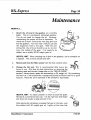
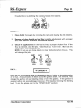
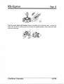
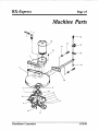
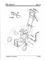
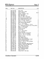
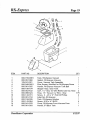
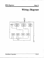
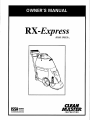
RX=Express
HIGH SPEED. ..
lSSA-
on Cleamg and Maintenance
11015
47th
Avenue
W, Mukilteo,
WA
98275
RX-Express
Table of Contents
Machine
Specifications
. . . . . . . . . . . . . . . . . . .
2
. . . . . . . . . . . . . . . . . . . . . . . . . . . . .
4
and Precautions
Operation
Instructions
Automatic
1
. . . . . . . . . . . . . . . .
Preparation
Cleaning
Page
Scrubber
. . . . . . . . . . . . . . . . . . . . .
Option
. . . . . . . . . . . . . . . .
6
7
Maintenance
. . . . . . . . . . . . . . . . . . . . . . . . . . 10
Repair Guide
. . . . . . . . . . . . . . . . . . . . . . . . . . 13
Machine
Wiring
Parts
Diagram
. . . . . . . . . . . . . . . . . . . . . . . . . 15
. . . . . . . . . . . . . . . . . . . . . . . . . 21
Warranty
Repair Policy . . . . . . . . . . . . . . . . . . . . 22
Warranty
. . . . . . . . . . . . . . . . . . . . . . . . . . . . . 23
Copyright
01998
~LEANMASTER”
Mukilteo,
Corporation
Washington
182-015
No part
electronic
of this manual
retrieval
may
systems)
be reproduced
without
or used
the express
in any form
written
Revised
or by any means
permission
August
(i.e.
graphic,
of the CLEANMASTER@
11,
1998
electronic,
Corporation.
photocopying
All rights
or
reserved.
RX-Express
Page 1
Machine Specifications
Size:
39”1 x 42”h
x 15”W
Weight:
14 oz.
Gearbox
Oil Capacity:
Vacuum
Motor:
(1) Three
Solution
Pump:
Diaphragm Type, Continuous
1.25 GPM -45 PSI Max
Solution
Tank Capacity:
Recovery
Tank Capacity:
Head Speed:
130
Duty,
By-Pass
8.5 gallons
8.0 gallons
RPMs
volts
1/2 HP
8.9 amps
Motor:
Automatic
Stage 5.7”
1 17“ H20 Lift -99 CFM
115
Scrubber
CleanMaster
Attachment
Ciq.wration
Kit:
1 Squeegee Attachment
1 Trailer Hook
1 Pad Driver Head or Brush Head Assembly
1 Head Removal Wrench
7/18/(95
RX=Express
Page 2
Preparation and Precautions ~~
TO PREPARE...
Carefully
remove the unit from its shipping container and inspect
damage from shipping has occurred, notify the carrier immediately.
for damage.
If
The unit may come partially disassembled.
Please refer to the exploded view for a
proper tank configuration.
Remove the solid shipping plug from the top of the gearbox
and replace it with the vented plug provided.
if there is any evidence of oil on any of the packaging material, or in the machine
itself, it may have come from the gearbox of the unit. Check the oil level of the
gearbox prior to the operation of the unit.
Important:
Remove the solid shipping plug from the top of the gearbox
it with the vented plug provided before operating the machine.
and replace
PRECAUTIONS
1.
To avoid hazardous conditions, do not use your machine
flammable
and/or explosive vapors or dust are present.
2.
Connect only to a grounded
See illustration.
in areas where
(3 wire) outlet.
row...
\
—
OW,,r
*X
3.
WARNING:
To reduce risk of electrical
use the
equipment
indoors
or
shock,
contained within a vehicle (i.e. service van).
Do not expose the machine to weather.
0
Q
a
“~
.-m
. ,M,,
m,,”
—
~
.Lm~
%“
II
OF
m+, , m.,,
4.
Grounding
mouom
m..,
H
Instructions:
The RX-Express should be grounded while in use ~
to protect the operator from electrical shock. The
power cords are equipped with suitable three conductor plugs.
If grounded
outlets are not available, use three way adapters (see Figure B). The green (or
green and yellow) conductor in the cord is the grounding wire.
Never connect
CleanMaster
Corporation.
7/18/95
RX-Express
Page 3
the grounding blade to a live terminal. Your terminal is designed to be used on
less than 150 volts and has plugs resembling the one shown in Figure A. A
grounding
adapter
is available
locally for connecting
plugs to 2-prong
receptacles.
The green (or green and yellow) right lug extending
from the
adapter must be connected to a properly grounded outlet.
NOTE:
Use only three wire extension cords which have three prong
grounding-type
plugs and three prong receptacles or adapters that accept
the appliance’s
plug. Replace or repair any damaged cords.
5.
Always
6.
Water heaters, when required,
Damage to the pumps
unit.
degrees.
7.
Empty the entire machine
8.
Do not allow the recovery tank to overfill
a defoamer should be used.
9.
After each use of the machine, rinse out and empty the recovery tank.
Then, with the recovery lid open and the vacuum hose off, run the
vacuum motor to allow the tank to dry.
10.
disconnect
Do not expose
CleanMaster
the machine
the machine
Corporation
from the electrical
outlet
before
servicing.
should be installed in-line, downstream
of this
will occur if water temperature
exceeds
160
of water
before trying to lift it.
to freezing
with liquid or foam.
If foam occurs,
temperatures.
4/21/98
RX-Express
Page 4
Operation
CONTROLS
There are four switches installed in the dash box located on the main handle assembly.
Two are for the VACUUM PUMP and CLEANING HEAD. The SOLUTION PUMP has two
switches:
1. Automatic,
and 2. Manual application of solution.
MANEUVERABILITY
The ease of handling the RX-Express is a direct
result of the rotary extractor head. Its natural
cleaning
motion provides the “drive” for the
The slightest push or pull against the
unit.
foam handle provides ample effort in guiding
the RX-Express
through
its cleaning paces.
Pivoting on its large front tires and the swivel
casters in the rear allow the RX-Express
to
glide in and out of tight spaces and turn on a
dime.
CLEANING
B3ckward ~
Movement
~
Forward
Movement
PATTERN
To achieve maximum results from your unit, it is recommended
that you clean
back-and-forth
motion while overlapping each cleaning pass by fifty percent.
more soiled the area to be cleaned, the slower the speed of the cleaning passes.
allows the machine more time to work. After cleaning an area approximately
six
square, turn off the solution switch and make vacuum-only “dry passes” over the
to assure maximum water removal and a faster drying time.
in a
The
This
feet
area
(,--–——————~
\
CleanMaster Corporation
“p..———
~__
-+1
7/18/95
RX-Express
Page 5
I
PUMP
PRIMING
MODE
Connect the auxiliary pump line supplied with the unit to the
male coupler at the rear of the machine.
Disconnect
the
vacuum hose intake from the left side of the clear dome and
place the end of the auxiliary line up into the opening in the
dome. Using your hand to create a seal around the line, turn on
the vacuum and solution pumps until you see water coming out
of the hose.
EMPTY
MODE
Connect
the auxiliary
pump line to the male
coupler at the rear of the machine and place the
oth& end into a drain. Turn on the solution switch
and allow the remaining water to be pumped free.
HEAD ASSEMBLY
/“k
I
(
LEVEL (HEEL-TOE)
1!
~u
k
Fran!VaGShoe
Rem
Sushing
Adjustment
A!
A+
ADJUSTMENT
Roll the machine onto a flat, hard surface
and lower the head to its cleaning position.
From the side, at floor level, look to see if
the front and rear shoes on the cleaning
head are making contact with the surface
If the front shoe is off the
simultaneously.
floor, the rear bushing must be loosened
and moved up. If the rear shoe is off the
floor, the bushing must be adjusted down.
On the star wheel, two one-inch rubber plugs have been inserted into the plastic hub.
This is to increase the airflow of the electric vacuum motor and speed up drying time.
Remove the plugs when cleaning the star to prevent the buildup of debris in the hub.
CleanMaster Corporation
7/14/98
RX-Express
Page 6
Cleaning Instructions
1.
Remove the top (recovery) tank and fill the lower (solution) tank with hot water.
The higher the temperature
of the water, the better the cleaning action of the
machine and the chemicals used. However, do not exceed a water temperature
of 160°F.
When accessible, fill the machine directly from a utility sink using
the hose supplied. When this is not an option, a clean, five gallon bucket will
suffice.
Add the necessary chemicals and replace the upper tank and dome.
Now you are ready.
CAUTION:
Only non-foaming cleaning solutions can be used and absolutely no
They will decrease the life of rubber
harsh solvents or petroleum products.
gaskets, diaphragms and seals.
2.
Attach
3.
Position
4.
Lower the cleaning head into its operating
located just behind the right front wheel.
5.
Turn on the switches
6.
To control the flow of solution, turn on either the AUTO switch for continual
flow or use the MANUAL button. Leave the AUTO switch off if the MANUAL button
is used.
7.
When making
either mode.
8.
At completion, dispose of the dirty water in the correct manner. Also, rinse the
recovery tank thoroughly
before reusing the machine.
NOTE:
To remove any standing water in the solution tank before storing,
simply attach the three foot clear hose to the rear of the machine.
Place the
other end of the hose in the recovery tank and turn on the pump to evacuate
the remaining water.
9.
At the end of the day, perform the daily maintenance
scheduled.
NOTE: The daily maintenance
will prevent any chance of accidental
the power
cord to a properly
the machine
20 amp receptacle.
in the area to be cleaned.
marked
a “dry pass”
CleanMaster Corporation
grounded
position
by releasing
the
latch
VACUUM PUMP and CLEANING HEAD.
(running
vacuum
only),
do not use the pump
in
freezing.
4/21/98
RX-Express
Page 7
Automatic Scrubber Option THE KIT INCLUDES
One (1) Squeegee Attachment
(mounting hardware
One (1) Trailer Hook
One (1) Pad Driver Head or Brush Head Assembly
One (1) Head Removal Wrench
INSTALLATION
INSTRUCTIONS
Remove the tanks.
Place the machine
1.
remove the standard cleaning head.
included)
on its right side and
2.
Thread on the cleaning head of your choice. Make sure that
it mounts counter-clockwise.
If you are using the pad driver
head, select the proper pad for the application.
3.
Attach the saueeuee
assemblv
,machine as seen below.
-+’
o
to the rear of the
u
Crossbar
&
Cable
Retainer
With the machine in its upright (cleaning) position,
hook the cable retainer
over the crossbar to
“disengage” the squeegee.
4.
5.
Add the appropriate solution.
Replace the tanks.
Lower the head onto the floor surface and turn on
the head and vacuum switches.
IMPORTANT:
DO NOT turn on the pump switch.
control the flow of solution.
\
Squeegee Assy
Use the push button
to
To resume carpet cleaning capabilities,
remove the pad driver head with the
Place the tip of the wrench into the holes in the pad and
wrench provided.
rotate in a clockwise direction.
t
CleanMaster Corporation
7/18/95
“ RX-Express
Page 8
PARTS
WITH
PAD DRIVER
PART NO
DESCRIPTION
033-039
094-009
143-007
164-001
174-003
016-053
033-099
076-023
052-057
052-288
106-001
Clamp, 1 %” Spring - Wand Holder
Nut, %-20 S/S Nylock
Screw, %-20 x 1” Eye Bolt
Tool, Head Remover
Washer, !4” SIS Flat
107-020
154-101
015-144
025-013
033-059
061-100
052-432
061-031
064-020
068-324
131-098
131-099
143-007
143-533
154-001
155-013
177-021
177-022
CleanMaster
(079-052)
Pad Driver Disk
Clamp
Jet, H VsVV 8004 s/s - Port RX’s
Nipple, 1/8” Brass Close
Coupler, 1A” Machined Rotary Union Fitting
P!U$J,
1/8” Brass
Double Thread RX Vac Hub
Spacer, Floor Scrub Brush/Pad
Bracket, Vac Nozzle Extension
Cable, Vacuum Nozzle Lift
Clamp, Floor Scrub Cable
Handler Floor Scrub Hook
Cuff, 1 %” Gray - For Wire Reinforced Vac Hose
Knob, Vac Inlet Manifold
Vac Nozzle
Hose, 1 %” Vac w/ Wire - Gray
Squeegee Material - 1” x 1/8” x 26”
Extrusion Only - 28” Floor Scrubber
Screw, %-20 x 1” Eye Bolt
Screw, 10-24 x % Pan Hd Phillips
Spacer, % x 5/16 - s/s Solenoid Valve
Spring, Propane Regulator - H/Htr
Wheel, Floor Scrubber Wall Guard
Caster, Floor Scrubber Vac Nozzle
Corporation
QTY
1
2
1
1
2
1
1
1
1
1
5
1
1
1
2.5 ft
2
1
2
1
1
2.125 ft
2
2
1
8
2
1
2
1
7/18/95
RX-Express
Page 9
PARTS
WITH
BRUSH ASSEMBLY
(079-050)
PART NO
DESCRIPTION
033-039
094-009
143-007
143-118
164-001
174-003
016-051
076-023
052-057
052-288
106-001
107-020
154-101
015-144
025-013
033-059
061-100
052-432
061-031
064-020
068-324
131-098
131-099
143-007
143-533
154-001
155-013
177-021
177-022
Clamp, 1 %” Spring, Wand Holder
Nut, ?4-20 S/S Nylock
Screw, %-20 x 1” Eye Bolt
Screw, #8 x %” HXWSHD
Tool, Head Remover
Washer,
%” s/s Flat
Brush, Floor Scrub
8004 s/s - Port RX’s
Jet, H 1/8VV
Nipple, 1/8” Brass Close
Coupler, 1/8” Machined Rotary Union Fitting
Plug, 1/8” Brass
Double Thread RX Vac Hub
Spacer, Floor Scrub Brush/Pad
Bracket, Vac Nozzle Extension
Cable, Vacuum Nozzle Lift
Clamp, Floor Scrub Cable
Handle, Floor Scrub Hook
Cuff, 1 %” Gray - For Wire Reinforced Vac Hose
Knob, Vac Inlet Manifold
Vac Nozzle
Hose, 1 ?4” Vac w/ Wire - Gray
Squeegee Material - 1” x 1/8” x 26”
Extrusion Only -28”
Floor Scrubber
Screw, X+-20 x 1” Eye Bolt
Screw, 10-24 x % Pan Hd Phillips
Spacer, % x 5/16 - s/s Solenoid Valve
Spring, Propane Regulator - H/Htr
Wheel, Floor Scrubber Wall Guard
Caster, Floor Scrubber Vac Nozzle
CleanMaster Corporation
QTY
1
2
1
2
1
2
1
1
1
1
5
1
1
1
2.5 ft
2
1
2
1
1
2.125 ft
2
2
1
8
2
1
2
1
7/18/95
RX-Express
Page 10
Maintenance
MONTHLY...
1.
Check the oil level in the gearbox on a monthly
basis.
This is a permanent
lubricated gearbox.
You do not need to change the oil.
However,
the proper oil level is important.
To
maintaining
check the oil level, remove the vent plug and look
Turn the “star” until you can see
into the gearbox.
the inspection
hole in the gear.
With the unit
sitting flat, the oil level should be up to, but not
over, the middle of the gear.
If oil needs to be
added, use a quality 80-90 weight gear oil.
HELPFUL HINT: When checking the oil level in the gearbox,
a dipstick.
The oil level should read 3/8”.
use a toothpick
as
2.
Remove and rinse the filter screen from the- flow control
valve.
3.
Change the felt seal. This is recommended
after every ten
hours of use. (For step by step instructions on removing the
cleaning head and the seal, please refer to the “REPAIR GUIDE”
section. ) Always keep a spare felt seal soaking in 30 weight oil. By immersing
the felt in oil, it will expand like a sponge and provide sufficient seal for a good
vacuum.
Place the worn seal back in the oil bath to rejuvenate.
HELPFUL HINT: An ideal container in which to soak the spare
felt seal is a commercial tuna can. It is the right size and shape
and does not require a large amount of oil.
\
>
*
After placing the refreshed, oil-soaked felt seal in the hub, coat
the surface with 30 weight gear oil. Lightly oil the inner hub
CleanMaster
Corporation
7/18/’95
RX-Express
threads
before
Page 11
re-attaching
the cleaning
head to the machine.
WEEKLY...
1.
Clean the lid thoroughly
by removing
2.
Remove and clean the pick-up hose filter inside the solution tank with a vinegar
and water solution to remove the chemical deposits.
3.
Check the applicator jets in the head to insure a proper solution flow.
If the
flow is restricted, clean the jets. Twist the jet out. Turn it over. Blow out any
obstructions
and reinstall the jet.
NOTE: Do not use any sharp objects to clear obstructions
from the jets. This
will damage the jets.
UNEVEN
the tanks
DRIBBLE
and clearing
the lid of debris.
CORRECTLY
ATOMIZED
DAILY...
~
Clean off any accumulated debris on the gearbox shaft or inside the threaded portion
of the hub. An accumulation of debris around the gearbox shaft, if not removed, may
damage the gearbox oil seal resulting in loss of oil in the gearbox.
If the gearbox is
operated without oil, severe damage may occur. (This requires removing the cleaning
head. To do this, please refer to the “REPAIR GUIDE” section. )
CleanMaster Corporation
4/21/98
RX=Express
Page 12
Coat themotor
shaft with lubricant before reinstalling the cleaning head. Locate the
head onto the shaft, making sure the threads are aligned properly, and rotate the head
counter-clockwise.
CleanMaster
Corporation
4/21/98
RX-Express
Page 13
Repair Guide
Make sure the machine
IMPORTANT
electrical parts.
is unplugged
before
the removal
of any
Removal of Cleaning Head:
1.
First, unscrew the head in the same direction it turns during
operation (or clockwise when looking from the underside).
2.
Once you have loosened the assembly, spin if off with your
hands. If the cleaning head is difficult to remove, you may
use a %“ socket wrench on the exposed center nut.
Replacing of Felt Seal:
A worn or “dried out” felt will not form a proper vacuum seal. This will impair the
extraction
capabilities of the unit. Therefore, the carpets are left more wet than is
desirable.
1.
Remove cleaning head assembly.
2.
Make sure felt is saturated with oil to insure a proper seal.
3.
Remove and reverse seal so that ‘“new” face is against hub.
NOTE: Alternating sides will temporarily extend the life of the felt. However,
the seal may need to be replaced.
4.
Reinstall head assembly.
NOTE: When reinstalling the head assembly, you should be able to “feel” the
felt compacting
against the seal plate during the last quarter rotation of the
head.
Removal of Vacuum Motor:
1.
Disconnect machine from power source.
2.
Remove hose from end of vacuum motor.
Remove 10-24 screws from side of frame.
3.
4.
Lift motor.
5.
Disconnect wires at terminal clips.
Removal and Re-installation
of Solution Pump:
1.
Disconnect machine from power source.
2.
Check that ail water has been evacuated from unit.
3.
Disconnect
?4” hoses on either side of pump.
4.
Remove four (4) 10-24 screws and nuts mounting pump to side of frame.
5.
Disconnect wires at wire nuts.
CleanMaster Corporation
7/18/95
RX-Express
6.
7.
Page 14
Remake wire connections
with new wire nuts.
Re-install in reverse order.
Removal of Fiow Control Valve:
1.
Disconnect
machine from power source.
2.
Evacuate all water from unit.
3.
Disconnect
%” and 3/8” hoses attached to valve.
4.
Remove male quick connect from top of frame.
5.
Remove %” elbow behind quick connect.
6.
Disconnect wires.
7.
Lift complete valve assembly from unit.
Removal of Cleaning Head / Pivot Frame Assembly:
1.
Disconnect
machine from power source.
2.
Remove vacuum hose attached to front of head.
3.
Remove hose attached to rotary union.
4.
Disconnect
wires at rear of motor.
5.
Remove control link from rear of shaft.
6.
Loosen two (2) set screws in pivot bearing.
7.
Remove spring from lifting mechanism.
8,
Pull head forward to disengage from frame.
...
CleanMaster
Corporation
7/18/95
RX-Express
Page 15
Machine Parts
22
I
4
(
21
L
,?i-
I
20
19
5
\
.1
18
17
13
/
10‘
CleanMaster Corporation
12
/
11
6/19/’96
RX-Express
Page 16
62
‘?
,, ;<
\;;:
‘“ ‘“
63L
“=---+”””’’--””
IJ
““”-’
.,x, “ ‘%?
Q
,
.,
L . ..>. .
J
5
%
/
54
\.
48
1.
d 0\ \
A
“ /“a
’47
52
&
w
CleanMaster
Corporation
12/26/97
RX-Express
ITEM
1
2
3
4
5
6
7
8a
8b
9
10
11
12
13
14
15
16
17
18
19
20
21
22
23
24
25
26
27
28
29
30
31
32
33
35
36
37
38
39
Page 17
QTY
PART NO
DESCRIPTION
000-052-099
000-052-276
Insert, #26
Rotary Union %“ NPT
Hose, 3/8” Rubber
Gearbox, Complete - Spur
Base, High Speed
Plate, Cast Base - Seal
Screw, % -20 x 1” s/s BHCS
Star, Stainless Steel Heat Treated
Hub, Double Thread RX Vacuum
Hose, 1” ID Gray - Vacuum
x %“ s/s, HHCS
Screw, 5/16 -18
Head, New RX Skid Assembly
Nut, % -20 S/S Nylok
000-068-017
000-059-001
000-006-009
000-105-008
000-143-166
000-107-089
000-107-020
000-068-174
000-143-012
000-064-012
000-094-009
000-143-162
000-076-057
000-052-089
000-052-080
000-057-047
000-055-057
000-094-009
000-085-012
000-015-145
000-143-080
000-143-096
000-174-021
000-106-014
604-052-012
000-157-111
000-100-017
000-143-315
000-061-001
000-061-026
000-108-012
000-061-029
000-085-010
000-141-023
000-052-309
000-111-124
000-033-004
CleanMaster Corporation
SCI%W,
5/16
X
I”
StriPP13r
%
-
ZO
1
1
43/16
S/S
Jet, 110015
Quick Connect (Jet, O-ring,
Elbow, ‘/8” Brass Female
Nipple, 1/8” x 4“ Brass
Gasket, Felt Hub
Frame, Pivot
Nut, % -20 S/S Nylok
Link, Torsion Bar
Bracket, Auto Floor Scrub Hitch
Screw, % -20 x 1” s/s SHCS
Screw, 3/8 - 16 x %“, s/s HHCS
Washer, 3/8” k)ck
Plug, Gearbox Vent
Electric Motor Assembly
Switch, Chrome Momentary
10224
Panel, RX-Express Switch
Screw, % -20 x %“ Rnd Hd Phillips
Handle, Foam Grip
Handle, RX-Express Upper Aluminum
Protector, Power Cord Relief Grip
Main Handle, RX-Express
Linkage, Steel Clevis Yoke
Rod, RX-Express Linkage
insert, #68 Plastic Elbow
Pump, Low PSI
Clamp, Size 6- Mini Hose
~t
1
1
1
1
1
1
5
5
5
5
5
Body)
5
5
5
1
1
2
1
1
2
5
12
1
1
1
1
2
2
1
1
1
1
1
2
1
4/21/98
‘,
RX-Express
Page 18
ITEM
PART NO
DESCRIPTION
QTY
40
41
42
43
44
45
46
47
48
49
50
51
52
54
55
56
57
58
59
60
61
62
63
64
65
000-052-117
000-052-050
000-057-055
000-174-011
000-052-090
000-052-071
000-052-085
000-052-061
000-169-119
000-052-104
000-068-018
000-141-025
000-177-018
000-141-026
000-055-056
000-177-019
000-015-141
000-111-129
000-052-117
000-052-448
000-157-115
000-143-167
000-094-034
000-143-051
000-106-033
Insert, #48
Quick Connect, 440 Male w/ Viton - Standard
Gasket, Garden Hose
Washer, 9/16” Brass - Fiber Glass
Tee, %” Male Branch M-F-F
Nipple, % Brass Hex
Elbow, %” Brass Street
Bushing, 3/8 M x !4 F Brass
Valve, 11 Ov Solenoid
Insert, #66
Hose, %” Rubber
Axle, RX-Express Rear
Caster, RX-Express Rear
Axle Assembly, High Speed RX-Express Front
Frame, High Speed RX-,Express
Wheel, RX-.Express Front
Bracket, Vat. Motor Mount - Acustek
Motor, 3-Stage Vac Acustek 120 volt
Insert, #48
Quick Connect, !4” Male x !4” FPT - Special
Switch, 16 amp Mini Rocker w/ Terminal
Screw, 10-24
x 1 % BTN HD s/s
S/S Nylock
Nut, 10-24
Screw, 8-32
x %” s/s Phil Binder Head
Plug, 20 amp Male Twist Lock
1
1
2
4
1
1
3
1
1
2
2 Ft
000-001-070
000-008-032
000-015-146
000-049-100
000-052-201
000-052-436
000-081-157
000-085-015
000-094-026
000-106-025
000-131-014
000-131-050
000-134-008
000-178-044
Adapter, 1 7/8” x 1 %” Vac Motor Outlet
Bearing, %” Pillow Block
Bracket, Acoustical Foam Support
Filter, Solution Pick Up
Sleeve, 1 ?4” Vacuum Inlet
Quick Connect,
?4” F x %” FPT
Label Set, Generic RX-Express Operating Inst.
Linkage, %-28 Ball Joint
Nut, Nylon Solution Feed Filter
Plug, #3 Rubber Stopper
Gasket, Roto Shroud
2%
Sheet Foam Set, 3-Piece Acoustical
Foam
Receptacle, 20 amp Female Twist Lock
Cord, 50’ Primary (includes part #1 34-008)
1
2
1
1
2
1
1
1
1
3
4
4
4
1
Not Shown:
CleanMaster Corporation
1
1
1
1
1
1
1
1
1
2
Ft
1
1
1
8/11/98
RX-Express
Page 19
11
12
11
ITEM
1
2
3
4
5
7
8
9
10
11
12
13
14
15
PART NO
DESCRIPTION
QTY
000-159-0361
000-057-060
105-041-001
000-049-0201
000-061-025
000-106-104
000-052-432
000-068-324
000-143-315
000-081-153
000-159-035
000-143-054
000-041-076
000-061-003
Tank, RX-fFxpress Vacuum
Gasket, RX-lSxpress Vacuum
Cover, Vacuum Tank Assembly
Filter Screen, Modified for RX-Expfess
Dome
Handle, RX-Express Vacuum Tank Bail
Stopper Assy, Clear Tank
Cuff, 1 %” Gray for Wire Reinforced Vac Hose
Hose, 1 %” Vacuum w/ Wire - Gray
Screw, K -20 x %“ Rnd Hd Phillips
Label Set, RX-Express
Tank, RX-Express Solution
Screw, 8-32 x %“ BHCS
Cover, RX-Express Front Vacuum Form
Handle, 6“ Black Tank
1
1
1
1
1
1
2
9 Ft
2
1
1
4
1
1
CleanMaster Corporah”on
8/15/97
RX-Express
Page 20
Accessory
Parts List
PART NO
DESCRIPTION
000-068-194
000-068-332
000-079-050
000-079-052
000-163-023
000-164-020
100-011-101
Hose, 1 %” x 15’ Vacuum
Hose, 15’ F x F Solution
Kit, Auto Scrubber with Brush Assembly
Kit, Auto Scrubber with Pad Driver
CM-1 Deluxe Upholstery Tool with LP Valve
CM-CHSV
Upholstery Tool 4“, Closed Head, 1 %” DIA
CM S1 1A Carpet Wand 11” LP Powder Coated, 1 %” s/s
Rotary Extractor Pad Driver with Hub
Rear Assembly, Auto Floor Scrubber
Rotary Extractor Brush Assembly with Hub
190-041-020
190-041-021
190-041-022
CleanMaster Corporation
6/19/96
RX-Express
Page 21
Witing Diagram
L
M:FmBMcKf
~“’m(”)
I
GREEN (14)
I
- ORANGE
L
CLEANING
HEAD
(14)
BLuE(1S)
SOLENOID
VALVE
1
SO#J;N
VACUUM
MOTOR
( “)
:
55 WHITE (12)
=
CleanMaster Corporation
7/21/97
~
RX-Express
Page 22
Warranty Repair Policy
When
requesting
warranty
information,
call or write
and
provide
the
following
information:
1.
2.
3.
4.
When and where the equipment in question
Model and serial number of machine.
Part number and description of part.
Description of failure or defect.
Upon receipt of the above information,
All packages
Authorization
After
should
number.
evaluation,
a Material
was purchased.
Return Authorization
be prepaid and clearly marked with the Material
Return
If these conditions are not met, shipment will be refused.
the item(s)
will be repaired or replaced
at our discretion.
If failure or defect is the result of physical abuse, or if the warranty
repairs will be charged to the customer.
For service,
contact the distributor
call our Customer
Monday
will be issued.
through
PST
CleanMaster Corporation
where the machine was purchased
Service Department.
Friday .8:00
Parts:
Service:
Parts and Service FAX:
ROCK MT.
period has expired,
(425)
(425)
(800)
am To 5:00
pm PST
775-7276
775-7275
426-4225
CENTRAL
EASTERN
or
RX-Express
Page 23
d-
tl
5 -3-1
WARRANTY
CleanMaster
products are warranted to be free of defects
either 5 years, 3 years, or 1 year as noted below:
*
*
*
*
5
3
1
1
in material
for a period of
Years on Roto Cast Molded Tanks
Years Prorated on Drive Motor Gearbox Assembly
(RX-Express
Year on Vacuum Motors, Pumps, Switches,
Fittings, Etc.
Year on HushhVac Vacuums
Only)
During this warranty period, we will repair or replace, at our sole option, free of charge,
any parts shown to be defective in either material or workmanship.
Said parts must be
returned with postage or freight pre-paid.
Specific parts, such as switches,
vacuum
motors,
pumps, fittings, etc., are also warranted for a period of 1 year from date of
original purchase.
parts or workmanship
only. IT DOES NOT
DUE TO DEFECTIVE
PARTS.
It
does NOT cover normal wear items such as hoses, power cords, bumpers,
carbon
brushes, gaskets, etc., which require replacement as a result of ordinary usage. Also,
failures caused by abuse, neglect-r alterations or operation contrary. to manufacturer’s
recommendations
are not warranted.
This warranty
is for replacement
PROVIDE FOR REPLACEMENT
of defective
OF COMPLETE UNITS
I
Replacements
period.
parts
are warranted
only for the remainder
of the
original
warranty
This warranty
does not cover labor or other charges in connection
with replacement
parts.
NO LOCAL SERVICE OR REPAIR CHARGES ARE ALLOWED UNLESS PRIOR
IS OBTAINED.
AUTHORIZATION
I
J
There
are no other warranties,
expressed
or implied, made with respect to this
equipment.
The manufacturer assumes no responsibility for damages resulting from the
use or misuse of this equipment.
~
CORPORA TION
11015
CleanMaster
47th
Corporation
Avenue
W
●
Mukiiteo,
WA
98275
4/24/97