1
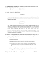
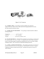
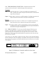
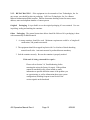
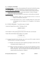
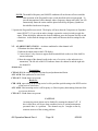
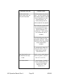
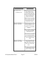
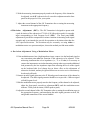
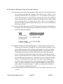
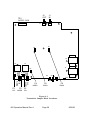
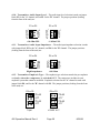
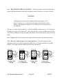
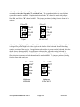
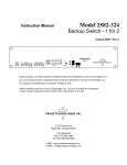
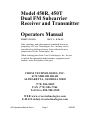
Model 450R, 450T
Dual FM Subcarrier
Receiver and Transmitter
Operators Manual
FIRST 8/10/98
REV A 8/26/99
Data, drawings, and other material contained herein are
proprietary to Cross Technologies, Inc., and may not be
reproduced or duplicated in any form without the prior
permission of Cross Technologies, Inc.
When ordering parts from Cross Technologies, Inc., be sure
to include the equipment model number, equipment serial
number, and a description of the part.
CROSS TECHNOLOGIES, INC.
6170 SHILOH ROAD
ALPHARETTA, GEORGIA 30005
(770) 886-8005
FAX (770) 886-7964
Toll Free 888-900-5588
WEB www.crosstechnologies.com
E-MAIL [email protected]
450 Operation Manual Rev A
Page 1
8/26/99
Model 450R, 450T Dual FM Subcarrier Receiver and Transmitter
Operators Manual
TABLE of CONTENTS
SECTION
TITLE
PAGE
Warranty........................................................4
OPERATORS SAFETY CONSIDERATIONS................5
1
1-1.
1-2.
1-3.
1-4.
GENERAL INFORMATION ................................. 7
INTRODUCTION ........................................................... 7
SPECIFICATIONS .......................................................... 7
SAFETY CONSIDERATIONS ............................................ 7
GENERAL DESCRIPTION ................................................10
2
INSTALLATION ............................................ 11
2-1. INTRODUCTION ........................................................... 11
2-2. INITIAL INSPECTION .................................................... 11
2-3. PREPARATION FOR USE ................................................ 11
2-4.
Power Requirements ..................................................... 12
2-5.
Line Voltage Selection ................................................... 12
2-6.
Power Cable ...............................................................13
2-7. OPERATING ENVIRONMENT .......................................... 13
2-8. RACK MOUNTING ........................................................ 13
2-9. AUDIO, ALARM CONNECTIONS... ................................... 13
2-10. VIDEO BASEBAND CONNECTIONS ................................. 14
2-11. VIDEO FILTERING ....................................................... 14
2-12. REPACKAGING ........................................................... 15
3
OPERATION ................................................ 16
INTRODUCTION .......................................................... 16
APPLYING POWER ....................................................... 17
CONTROL SWITCHES ................................................... 17
STATUS CHANGES ...................................................... 17
ALARM INDICATIONS .................................................. 18
TROUBLESHOOTING .................................................... 19
3-1.
3-2.
3-3.
3-4.
3-5.
3-6.
450 Operation Manual Rev A
Page 2
8/26/99
TABLE of CONTENTS
SECTION
4
TITLE
PAGE
ADJUSTMENTS and OPTIONS ........................... 22
4-1. INTRODUCTION ........................................................... 22
4-2. RECOMMENDED TEST EQUIPMENT ................................. 22
4-3. TRANSMITTER FRONT PANEL ADJUSTMENTS .................. 23
4-4.
Level Adjustment (IF) ................................................... 23
4-5.
Deviation Adjustment (DEV) ........................................... 24
4-6. RECEIVER FRONT PANEL ADJUSTMENTS ........................ 26
4-7.
Squelch Adjustment ..................................................... 26
4-8.
Audio Adjustment ........................................................ 27
4-9. TRANSMITTER INTERNAL OPTIONS ................................ 27
4-10.
Audio Input Level ....................................................... 29
4-11.
Audio Input Impedance ................................................. 29
4-12.
Emphasis Type (with Compressor OUT) ............................ 29
4-13. RECEIVER INTERNAL OPTIONS ...................................... 30
4-14.
Audio Output Level & Impedance .................................... 30
4-15.
Emphasis Type (with Expander OUT) ............................... 32
4-16.
Input High Pass Filter .................................................. 32
450 Operation Manual Rev A
Page 3
8/26/99
WARRANTY
This Cross Technologies product is warranted against defects in material and workmanship for one
year from the date of shipment. During this period Cross Technologies will either repair or
replace, at its option, products which prove to be defective.
To obtain service under this warranty, this product must be returned to Cross Technologies at its
address. Buyer shall pay all shipping charges to Cross Technologies, and Cross Technologies
shall pay all charges for return shipment to buyer. When this product is to be returned from
outside the United States, buyer shall pay all shipping charges, taxes, duties or other reasonable or
necessary costs to transport the product safely in both directions.
LIMITATIONS AND EXCLUSIONS
This warranty shall not apply to defects resulting directly or indirectly from any of the following:
Improper or inadequate maintenance.
User-supplied interfacing or connected equipment.
Operation beyond the specifications of the unit or under severe
environmental conditions.
Improper facility preparation or maintenance.
No other warranty is expressed or implied. Cross Technologies specifically
disclaims any implied warranties of merchantability or fitness for any particular
purpose. Under no circumstances shall Cross Technologies be liable for any
incidental, indirect or consequential damages or losses, whether or not Cross
Technologies has any advance notice of the possibility of such damages.
Correspondence:
CROSS TECHNOLOGIES, INC.
6170 Shiloh Road, Alpharetta, GA 30005
Telephone (770) 886-8005
FAX (770) 886-7964
Toll Free (888) 900-5588
E-mail [email protected]
450 Operation Manual Rev A
Page 4
8/26/99
OPERATORS SAFETY CONSIDERATIONS
General
The general safety information in this documentation is for operating and servicing personnel.
Specific warnings and cautions will be found throughout the manual where they apply and may or
may not appear here.
Safety Symbols
___________
_ WARNING _
___________
WARNING symbols indicate a condition, practice or procedure that, if not properly performed or
adhered to, could result in personal injury or loss of life.
CAUTION
CAUTION symbols indicate a condition, practice or procedure that, if not properly performed or
adhered to, could result in damage to the equipment or other property.
Before Applying Power
CAUTION
Verify that the voltage selection on the power receptacle matches the line voltage and the proper
fuse is installed. See Section 2.
___________
_ WARNING _
___________
This equipment is grounded through the grounding
conductor of the power cord supplied with the unit. To
avoid electrical shock, plug the power cord into a properly
wired receptacle. An uninterruptible safety earth ground
must be provided from the main power source to the
equipment via the power cord. Grounding one conductor of
a two conductor wiring system or cord is not sufficient
protection.
450 Operation Manual Rev A
Page 5
8/26/99
OPERATORS SAFETY CONSIDERATIONS
(Cont'd.)
___________
_ WARNING _
___________
Danger From Loss of Protective Ground
Upon loss of the protective ground connection, all accessible
conductive parts can render an electrical shock.
Do Not Remove Covers or Panels
To avoid personal injury or shock, equipment should not be
operated without covers or panels.
Servicing
Servicing instructions are for the use of qualified servicing
personnel only. Some adjustments described in this manual
are performed with power applied to the equipment and the
cover removed. To avoid dangerous shock, only qualified
service personnel should perform maintenance.
LCD Display Module
The LCD Display Module mounted in the front panel is
fragile. Care should be taken not to break the exposed glass
panel. If broken, extreme caution should be used to avoid
cuts from sharp edges. If the liquid crystal material touches
your skin or clothes, wash it off immediately using soap and
plenty of water. Do not allow any of the liquid crystal
material to get in your mouth.
450 Operation Manual Rev A
Page 6
8/26/99
Section 1 - GENERAL INFORMATION
1-1. INTRODUCTION.
This manual contains information necessary for the installation, operation, testing and alignment of
the Model 450 FM Subcarrier. The documentation for this product is divided into five sections as
described below.
Section 1.
General_Information: provides general information about this equipment, circuit
description and specifications.
Section 2. Installation: provides installation information including initial inspection, installation and
repackaging the equipment.
Section 3. Operation: provides information about front panel checks and settings.
Section 4. Performance_Tests: provides information to verify the performance of the equipment.
Section 5. Adjustment & Options: provides information to adjust the equipment, and to select the
various options.
1-2. SPECIFICATIONS.
The specifications are listed in Table 1-1. These are performance standards to which the Model
450 is aligned and tested.
1-3. SAFETY CONSIDERATIONS.
Safety information, relating to installation, testing, etc. is found throughout this manual. Please
refer to OPERATORS SAFETY CONSIDERATIONS at the beginning of this manual.
CROSS TECHNOLOGIES INC.
DEV
IF
DEV
IF
CROSS TECHNOLOGIES INC.
SQUELCH
AUDIO SQUELCH
AUDIO
5.41MHz
6.17MHz
6.20MHz
6.80MHz
450 SUBCARRIER
TRANSMITTER
PROGRAM
ALARM
A
B
EXECUTE
450 SUBCARRIER
RECEIVER
PROGRAM
ALARM
A
B
EXECUTE
Figure 1.1 450 Subcarrier Transmitter and Receiver
450 Operation Manual Rev A
Page 7
8/26/99
TABLE 1-1 SPECIFICATIONS
Audio Interface:
Input/Output
Frequency range ..................... 40 Hz to 15 kHz
Peak program level ................. +9 or+18 dBm selectable
Impedance ............................ 600Ω or high Z in 600Ω or low Z out Balanced,
transformer coupled
Connector type ...................... Terminal block
Audio Characteristics: (with 3:1 compandor and emphasis)
Dynamic range ....................... >90 dB
Frequency response ................ ±0.25 dB
Total harmonic distortion
(1 kHz @ PPL) ...................... <0.1%
Intermodulation distortion .......... <1%
Interchannel phase difference
1000 Hz ........................ <6°
50 Hz and 15 kHz ............ <10°
Compandor type .................... 3:1 improved
Modulator Characteristics:
Output frequency range ............ Frequency agile from 1.0 to 9.99 MHz in 10kHz steps.
Frequency stability ................. ±300 Hz over operating temperature range.
Connector type ...................... BNC Female
Peak carrier deviation(PPL) ....... ±75 kHz (adj.)
Subcarrier level ...................... 25 to 100 mV P/P (adj.)
Output impedance ................... bridging (>4 k ohms)
Demodulator Characteristics:
Input frequency range .............. Frequency agile from 1.0 to 9.99 MHz in 10 kHz steps.
Operating channel spacing ......... 280 kHz, minimum
Connector type ...................... BNC Female
Impedance ........................... bridging (>4 k ohms)
Input level ............................ 25 to 100 mV
Recommended operating conditions for satellite applications ...... C/n≥61 db•Hz
450 Operation Manual Rev A
Page 8
8/26/99
TABLE 1-1 SPECIFICATIONS
(Cont'd.)
Power Requirements:
Standard...............................115/230 VAC (47-63 Hz)
Environmental Requirements:
Ambient temperature for:
Storage .......................... -20°C to +70°C
Specification .................... +10°C to +40°C
Humidity. ............................ 95% maximum
Altitude:
Storage .......................... 12,200 meters(40,260 ft.) ASL
Specifications .................... 3,050 meters(10,000 ft.) ASL
Alarms:
Front panel visual and Form C contact.
Receiver ............................. Operates upon degradation of either carrier or frequency.
Transmitter .......................... Operates upon degradation of either carrier frequency or
loss of synthesizer lock.
Dimensions:
2 channel transmitter ................ 44.4 mm (1.75") H X 483 mm (19")W
X 381 mm (15")D
2 channel receiver ................... same as above
450 Operation Manual Rev A
Page 9
8/26/99
1-4.GENERAL DESCRIPTION.
The Model 450 Dual FM Subcarrier System consists of two complete frequency agile FM
transmitters or receivers in a single enclosure. A common microprocessor circuit is used to
program the operating frequencies of the channels, monitor alarm conditions, and configure some
system options. The microprocessor circuit incorporates a non-volatile memory device that retains
the most recent settings indefinitely during power outages or prolonged storage.
The 450 was designed to provide the wide dynamic range, low distortion transmission path
required for today's digitally mastered and recorded program material, while maintaining the
traditional bandwidth and poor-path performance advantages of analog FM techniques. Essential
to accomplishing this is a newly designed precision audio noise reduction system. This system
consists of a dynamic range compressor in the transmitter, and a complementary dynamic range
expander in the receiver. The compressor/expander ("compandor") system incorporates fast attack
RMS detection, multipole pre- and de-emphasis, overshoot limiting, and audio bandwidth filtering.
For applications requiring compatibility with existing uncompanded subcarrier equipment, the
compressor and expander can be switched out of the signal path by the microprocessor. Internal
jumper options then select either 75 uS or CCITT J.17 emphasis networks (75uS factory setting).
The video baseband is combined with the subcarrier signals in the transmitter by a low component
count passive directional coupler. This circuit has been designed to put virtually no load on the
video line (>4 K ohm), allowing multiple units to be "daisy-chained" without adversely affecting
the signals on the baseband. The low component count and passive nature of this circuit provide
excellent protection against disruption of the baseband due to component failure or loss of power in
the 450.
While the 450 Subcarrier system is most often used in conjunction with video signals, the wide
operating frequency range and narrow bandwidth also make the unit attractive for multi-channel
applications on a video baseband without video. To accommodate these applications, the 450
Receiver incorporates an internal jumper option to bypass the input highpass filter that normally
protects the discriminator circuits from the high level video signal. With the highpass filter
strapped out, the entire baseband is available to the receiver.
450 Operation Manual Rev A
Page 10
8/26/99
Section 2 INSTALLATION
2-1. INTRODUCTION. - This section contains instructions for installing and interfacing the
Model 450 Dual FM Subcarrier. Included are initial inspection procedures, power and grounding
requirements, line voltage selection, interface connections and instructions for repackaging the
equipment.
2-2. INITIAL INSPECTION.
___________
_ WARNING _
___________
In the event that any portion of the outer enclosure of the unit has been damaged, a
hazardous electrical shock condition may exist. In this case, do not apply power to
the unit, or attempt to perform electrical tests.
Inspect the shipping container for damage. The shipping container and cushioning material should
be kept until the contents of the shipment have been checked for completeness and the equipment
has been checked mechanically and electrically. This equipment was carefully inspected both
mechanically and electrically before shipment. It should be free of mars and scratches and in
perfect electrical order upon receipt. If there is mechanical damage or defect due to shipment,
notify the carrier immediately. Keep the shipping material for the carrier's inspection. In the
event of mechanical damage, or if the equipment does not pass electrical performance tests, notify
the Cross Technologies, Inc. office immediately. The warranty statement is located in the front of
this manual.
2-3. PREPARATION FOR USE. - Each unit is shipped from the factory with the following
strapping options:
Factory Setting
Optional Setting
Audio level (PPL) ...................... +18 dBm .............. +9 dBm
Audio impedance (Transmit) ............. 600 Ω ................ low Z
Audio impedance (Receive) .............. 600 Ω ............... high Z
Emphasis (with Compandor OFF) ....... 75 µs .............. CCITT J.17
Highpass filter (Receive) ............. IN (Video present) ... OUT (no Video)
Power ................................... 105-130 Vac .......... 210-250 Vac
To change the line voltage setting of your unit, please refer to Paragraph 2-5. To change the other
settings, please refer to Section 5.
450 Operation Manual Rev A
Page 11
8/26/99
2-4. POWER REQUIREMENTS. - The Model 450 requires a power source of 105V-130V
50-60Hz or 210V-250V 50-60Hz. Power consumption is:
Transmitter.................. 28 VA maximum.
Receiver..................... 24 VA maximum.
2-5. LINE VOLTAGE SELECTION.
CAUTION
Before connecting ac power to this equipment, make sure it is set to the line voltage of the
power source. Also ensure that the common connection of the power outlet is connected to
a protective earth contact.
___________
_ WARNING _
___________
Line voltage selection is made at the ac plug-in receptacle on the rear of the shelf (see
Figure 2.1). This should be done by trained service personnel only. To avoid electrical
shock, make sure the power cord is disconnected before changing the voltage selection pc
board. Before connecting this device to the power source, verify that a
protective earth ground connection is provided through the grounding conductor of the
power cord. The protective ground connection through the power cord grounding
conductor is essential for safe operation.
The Model 450 is shipped from the factory with the line voltage selection set for 105-130 Vac. If it
is necessary to change the line voltage selection, access to the voltage selection pc board can be
accomplished by (see Figure 2.1):
1.) Removing the ac cord.
2.) Open the cover door, rotate the fuse-pull to the left, removing the fuse.
3.) Remove the pc board. Select operating voltage by orienting the pc board to
position desired voltage on top-left side. Push board firmly into module
slot.
4.) Rotate fuse-pull back into normal position and re-insert fuse into holder,
using caution to select the proper fuse value.
450 Operation Manual Rev A
Page 12
8/26/99
Figure 2.1 AC Connector
2-6. POWER CABLE. - In accordance with safety standards, this equipment is
supplied with a three conductor cable. When connected to an appropriate power line outlet,
this cable grounds the instrument cabinet.
2-7. OPERATING ENVIRONMENT. - The operating environment should be within the
following limitations:
Temperature........................ +10 °C to +40 °C
Humidity........................... 95% maximum
Altitude........................... 3050 meters(10,000 ft.) ASL
2-8. RACK MOUNTING. - The Model 450 is intended for rack mounting in a rack having an
EIA standard width of 482.6 mm (19 inches). It is shipped from the factory with the mounting
brackets set for flush mounting. Optionally the mounting brackets can be reversed for extended
mounting (5 inches). Four 12-24 screws are required for mounting in the rack.
2-9. AUDIO, ALARM CONNECTIONS. - Audio and alarm connections are made at the 9
position terminal block on the rear of the equipment. A thin-bladed flat screwdriver is required.
Connections are made as marked on the rear panel. Terminals will accept wire sizes up to 12
AWG maximum.
450 Operation Manual Rev A
Page 13
8/26/99
2-10. VIDEO/BASEBAND CONNECTIONS. - Baseband connections are BNC
connectors on the rear of the shelf. A detailed description of the connections are:
Transmitter:
Input ... Video input from video source. If video is not used this port is terminated with 75
ohms. In multiple-unit operation, the input of units after the first is connected to the
output of the preceding unit.
Output ..Composite output to microwave or satellite transmitter. In multiple unit operation, the
output of all but the last unit connects to the input of subsequent units.
Receiver:
Input ... Composite input from microwave or satellite receiver. In multiple-unit operation, the
input of units after the first is connected to the output of the preceding unit.
Output .. Video output to monitor or video receiving equipment. If video is not used, this port
is terminated with 75 ohms. In multiple unit operation, the output of all but the last
unit connects to the input of subsequent units.
2-11. VIDEO FILTERING. - The video source should be adequately filtered to prevent
harmonics or other high frequency components from interfering with the low level subcarrier
signals in the upper part of the baseband. If the video signal source does not include a suitable
lowpass filter, a video lowpass filter should be added to the system between the video source and
the first subcarrier transmitter.
At the receive site, video quality is improved by using a filter to remove the high frequency
subcarrier signals prior to the video equipment. If an adequate video lowpass filter is not included
in the video receiving equipment, one should be added between the last subcarrier receiver and the
video equipment.
CAUTIOFOR CONTINUOUS
FIRE PROTECTION
N:
REPLACE ONLY WITH
SPECIFIED
TYPE RANGE
AND
LINE
VOLTAGE
FUSE 250V
RATED FUSE
105V-130V 50-60Hz
2 A
210V-250V 50-60Hz
1 A
INPUT
OUTPUT
CAUTION: NO
OPERATOR
SERVICEABLE PARTS
INSIDE. REFER
SERVICING TO
QUALIFIED
PERSONNEL.
N
O
C
O N
M C
ALM
T
R
A
T
R
B
Figure 2.2 450 Subcarrier Transmitter and Receiver Rear Panel
450 Operation Manual Rev A
Page 14
8/26/99
2-12. REPACKAGING. - If the equipment is to be returned to Cross Technologies, Inc. for
any reason, care should be taken in packaging. Call Cross Technologies, Inc. for a Return
Material Authorization (RMA) number. Enclose documents detailing reason for return, return
address, name and telephone number of contact person.
Original Packaging. It is preferable to use the original packaging if it was retained. Use care
in packing, sealing and marking the container.
Other Packaging. The general instructions below should be followed if re-packaging is done
with commercially available material.
1. A strong container should be used. Minimum requirement would be of singlewall
construction, 200 pound test material.
2. The equipment should be wrapped in plastic with 3 to 4 inches of shock absorbing
material on all sides. Anti-static material is preferred but not mandatory.
3. Seal the container securely. Be sure the container is properly marked.
If the unit is being returned for repair:
Please refer to Section 3-6, Troubleshooting, before
returning the unit to the factory for repair. If the problem
cannot be remedied locally, please include as much
information as possible about the nature of the problem you
are experiencing, as well as information about your system
configuration, including frequencies and levels of the
various signals on the baseband.
450 Operation Manual Rev A
Page 15
8/26/99
Section 3 OPERATION
3-1. INTRODUCTION. - This section describes operation of the front panel controls. There
are three operator switches, the LCD display and an alarm indicator. All functions for both A and
B channels are controlled by these components. The functions are:
1. Turn either channel "on" or "off".
2. Set frequency of either channel.
3. Activate or deactivate the compressor/expander.
Alarm indications appear on the LCD display but are not controlled by the operator.
Both hardware and software have been designed to make reprogramming as "tamper proof" as
possible. The Program/Execute switch is recessed so it will not inadvertently be operated. All
program changes must start with the operation of the Program/Execute switch and must end with
the operation of the Program/Execute switch. If this sequence is not followed, none of the changes
will take effect. If programming is initiated and no operator action takes place for approximately
12 seconds (before the final press of the Program/Execute switch) the display will revert to its
previous status and you will need to start over.
3-2. APPLYING POWER.
NOTE: The last status of a unit is retained even when power is removed. The next time power is
applied, the unit will return to it's previous settings.
When power is first applied, the LCD display goes through four steps.
1. The LCD goes black to show all segments are functioning.
2. The display will show the unit model number.
__________________
__________________
_450 Transmitter _
or
_450 Receiver _
__________________
__________________
3. The software version will be displayed.
__________________
_Software Rev #.#_
__________________
4. The present status of both channels is shown.
Note: Information for the "A" channel is given in the left-hand half of the display
window, and for the "B" channel in the right-hand half.
The unit is now operational and ready for any changes the operator may desire.
450 Operation Manual Rev A
Page 16
8/26/99
3-3. CONTROL SWITCHES.
1. Program/Execute. Any change to the programming of the unit must be initiated by pressing
the Program/Execute switch and completed by pressing the Program/Execute switch.
2. Cursor Movement - Horizontal. This switch is mounted so its movement is horizontal
and moves the cursor left or right. It is also used to select the "A"(left) or "B"(right)
channel at the beginning of programming.
3. Vertical Switch. This switch is mounted so its movement is vertical and has two functions:
A) During frequency changes, the vertical movement will raise or lower the
frequency in the direction of the arrows.
B) For other functions such as on/off or compandor disable, the vertical switch
will alternately turn the function on or off regardless of the direction
operated.
3-4. STATUS CHANGES. - To modify the status of a channel:
1. Operate the Program/Execute switch. The display will read:
__________________
_MODIFY A OR B ? _
__________________
2. Select channel A or B by operating the horizontal switch in either the A or B direction.
3. Status of the selected channel will be displayed. For example:
__________________
_A 6.60MHz ON _
__________________
4. By using the horizontal rocker switch the cursor can be moved left or right to either the
ON/OFF position or to any digit of the frequency.
A. If ON/OFF is selected, the status can be modified by operating the vertical switch. This
will alternately turn the channel on or off.
B. If changes are desired in the frequency, move the cursor to the digit that you wish to
modify. By using the vertical switch, that digit can be raised or lowered by the
direction of the arrow. The cursor can then be moved to another digit and the action
repeated until the desired frequency is displayed.
450 Operation Manual Rev A
Page 17
8/26/99
NOTE: The modified frequency and ON/OFF condition will not become effective until the
final operation of the Program/Execute switch described in the next paragraph. To
prevent interruption of other channels when a frequency change takes place, the 450
automatically mutes the carrier until the phase locked loop frequency synthesizer
has stabilized at the new frequency.
5. Operate the Program/Execute switch. The display will now show the Compressor or Expander
status (IN/OUT). If you wish to make a change, operate the vertical switch to toggle the
status. When the display indicates the desired condition, press the Program/Execute switch
a final time. At this time the changes you have made will become the new settings for the
channel.
3-5. ALARM INDICATIONS. - An alarm condition for either channel will:
1. Illuminate the alarm indicator,
2. Indicate the alarm status on the LCD display,
3. Cause a form C relay closure to appear at the terminal block on the rear of the shelf for
remote indication.
4. Mute the output of the channel (audio in the case of a receiver, or the subcarrier in a
transmitter). The left side of the LCD indicates alarms for channel A and the right side
for channel B.
Alarms are:
Transmitter :
CXR ALM if the carrier frequency deviates beyond predetermined limits.
AFC ALM if the synthesizer is out of lock.
CXR AFC if both alarms are present.
Receiver:
CXR ALM upon a drop in incoming carrier level beyond the squelch setting or the RF/IF section
of the receiver is defective.
AFC ALM if the incoming carrier is off frequency or if the frequency determining elements of the
receiver are defective.
CXR AFC if both alarms are present.
CAUTION
An annoying remote alarm can be disabled by turning the channel "off". If
this is done there will be no alarm condition active to remind maintenance
personnel there is a problem. The channel may be brought on-line by
someone unaware of the existing problem.
450 Operation Manual Rev A
Page 18
8/26/99
3-6. TROUBLESHOOTING.
In the event of difficulty with the 450 Subcarrier System, the following list of possible causes
should be reviewed prior to contacting the factory for repair. In the event that factory repair is
deemed necessary, please refer to Section 2-12., Repackaging, for information on returning the
unit.
PROBLEM/SYMPTOM
POSSIBLE CAUSE
Audio sound quality not
acceptable. Symptoms
could include one or
more of the following:
If Compressor/Expander are
being used, both ends must
be set IN. If not being
used both ends must be set
OUT. (See Section 3-4)
High distortion
Poor frequency resp.
Sounds too loud
(compressed)
Sounds too quiet
(expanded)
Sounds noisy
If Compressor/Expander are
not being used, check internal emphasis selection. (See
Section 4-12 & 4-16) Both
ends must be set the same.
Audio is noisy, but
sounds normal in other
respects.
Transmission path noise may
require use of companding
for acceptable noise performance. Set Compressor and
Expander IN and re-evaluate.
(see Section 3-4)
If Compressor and Expander
are both IN, system may be
operating below threshold.
Check other system components and antenna pointing.
In non-video systems, if the
subcarrier frequency is less
than about 4.5MHz, the high
pass filter in the receiver
may not be set OUT. (See
Section 4-17.)
450 Operation Manual Rev A
Page 19
8/26/99
PROBLEM/SYMPTOM
Audio sounds noisy.
Tones, chirps, buzz, etc
may also be present.
POSSIBLE CAUSE
Channel spacing may be too
close. The 450 requires 280
kHz between adjacent channel
center frequencies to meet
all specifications. At
closer spacings some of
these symptoms may appear.
The subcarrier channel may
be co-located with one of
the harmonics of a video
signal component (e.g.,
colorburst). Shift subcarrier frequencies and reevaluate.
Total baseband power may be
too high, leading to intermodulation products. Reduce
the level of the subcarriers
and/or video and reevaluate.
In systems with video, the
high pass filter in the receiver may be set OUT.
(See Section 4-17.)
Audio level and/or carrier deviation too high
or low.
LCD display blank.
450 Operation Manual Rev A
Verify correct audio impedance for system. (See Section 4-11 or 4-15.)
Loss of power. Possible
causes include blown fuse,
incorrect line voltage
selection, etc. (See
Section 2-5.)
Page 20
8/26/99
PROBLEM/SYMPTOM
LCD display shows:
NV Memory Error
Receiver LCD display
indicates a CXR alarm.
POSSIBLE CAUSE
A checksum error was found
after reading the nonvolatile memory device.
The unit may still be used
(press the Program/Execute
switch to proceed) but
should be returned for
repair as soon as convenient
since a power interruption
may cause loss of the unit's
programmed settings.
Receiver may be set to an
incorrect frequency, or the
transmit site may not be
operating on the specified
frequency.
Receiver SQUELCH adjustment
may need to be changed.
(See Section 4-7)
The subcarrier transmitter
for the specified frequency
may not be operating, or may
be at a reduced carrier
level.
Receiver LCD display
indicates an AFC alarm.
Any of the situations described above for a CXR
alarm may, under some conditions, also cause an AFC
alarm.
The receiver may be tuned to
a wide deviation channel
which it is unable to track.
450 Operation Manual Rev A
Page 21
8/26/99
Section 4 - ADJUSTMENTS and OPTIONS
4-1. INTRODUCTION. - This section describes operator adjustments and the selection of the
internal options. For a discussion of the microprocessor-controlled functions (Channel ON/OFF,
FREQUENCY and compandor IN/OUT) please refer to Section 3-4. For a discussion of line
voltage selection, please refer to Section 2-5. Throughout this section, the terms PPL and APL
are used in referring to audio levels. For a thorough discussion of these terms and equivalent
CCITT test levels, please refer to Appendix A.
The operator adjustments are located on the front panel on both the transmitter and receiver. The
transmitter adjustments consist of subcarrier level and deviation trims. The receiver adjustments
consist of squelch threshold and audio output level trims.
The internal options include selection of audio levels and impedances, emphasis type (with
companding OUT), and the receive highpass filter. These options are configured at the factory
prior to shipment as follows:
Audio Input/Output Levels .............. +18 dBm
Audio Impedance ......................... 600 Ω
Emphasis Type ............................75 µS
Receive Highpass Filter .................... IN
These settings will be suitable for the majority of applications, and should only rarely need to be
changed.
4-2. RECOMMENDED TEST EQUIPMENT.
Note: The equipment listed below comprises all of the test equipment mentioned in this
section. It is not necessary to have all of these items on hand to perform the adjustments.
Refer to each subsection for the specific items needed.
Item
Manufacturer & Model
Audio Analyzer ................... HP 8903B
Modulation Monitor .............. Marconi TF2300A
AC Voltmeter ...................... Fluke 8920A
Spectrum Analyzer ................HP 8552B/8553B
Frequency Selective VM ........ HP 3586C
Oscilloscope .........................Tektronix 2235
75 Ohm 1% BNC Termination .. Any
Equivalent equipment is acceptable. The specifications of the alternate instrument
should be significantly better than the accuracy of the measurement made.
450 Operation Manual Rev A
Page 22
8/26/99
4-3. TRANSMITTER FRONT PANEL ADJUSTMENTS.
NOTE:Prior to setting levels be sure transmitter is ON and set to proper frequency. See Section 3.
4-4. Level Adjustment (IF). - Determine the desired subcarrier level for your specific system.
The 450 Transmitter subcarrier level can be adjusted over the range of 25 mV to 100 mV p/p
(approx. -18 TO -30 dB, 75 ohm).
A. Level Adjustment Without Video or Other Channels. - If it is possible to set the
subcarrier level with all other signals (i.e., video and all other subcarriers) removed from the
baseband, the desired subcarrier level may be set directly using an oscilloscope or wideband AC
voltmeter. Please note that it is necessary to set the second channel within the 450 Transmitter to
the OFF status in order to use this method. If it is necessary to adjust the subcarrier level in a
"live" circuit with video and/or other subcarriers present, proceed to the method described in
Paragraph B., below; otherwise, proceed as follows:
1. Connect the INPUT BNC connector of the 450 Transmitter to a suitable 75
Ohm termination.
2. Connect the OUTPUT BNC connector of the 450 Transmitter to the measuring
instrument (either an oscilloscope or wideband AC voltmeter). If the measuring
instrument has a high impedance input (normally the case), this line should also
be terminated with a suitable 75 ohm termination.
3. Make certain that the second channel of the 450 Transmitter (whichever channel
is not now being adjusted) is set to the OFF Status.
4. Adjust the IF (subcarrier level) screwdriver adjustment on the front panel for the
proper system level.
5. The other channel may now be adjusted by reversing the ON/OFF status of the
two channels.
B. Level Adjustment With Video and/or Other Channels. - When other signals (such as
video or other subcarrier channels) are present on the baseband, it is necessary to use a measuring
instrument that can be tuned to the desired signal (such as a spectrum analyzer, frequency selective
level meter, or modulation meter with level measuring capability). Proceed as follows:
1. If the measuring instrument has a high impedance input, connect it to the
baseband signal at any convenient point after the insertion of the subcarrier
to be adjusted. If the measuring instrument has a low impedance (i.e., 75 or
50 ohm) it is necessary to connect the instrument to an isolated monitor
point in order to prevent the additional load presented by the low impedance
input from affecting the level to be measured.
450 Operation Manual Rev A
Page 23
8/26/99
2. With the measuring instrument properly tuned to the frequency of the channel to
be adjusted, set the IF (subcarrier level) screwdriver adjustment on the front
panel for the proper level for your system.
3. Adjust the second channel of the 450 Transmitter after re-tuning the measuring
instrument to the appropriate frequency.
4-5.Deviation Adjustment (DEV). - The 450 Transmitter is designed to operate with
a peak deviation of the subcarrier of 75 kHz (150 kHz peak-to-peak) for an audio
input corresponding to Peak Program Level (PPL). The front panel DEV
adjustment is provided to compensate for minor variations in incoming audio signal
strength, and is not intended to provide for operation at deviations other than the
450's specified deviation. The deviation may be accurately set using either a
modulation meter or a spectrum analyzer; choose the method you find most suitable.
A. Deviation Adjustment Using a Modulation Meter.
1. If the modulation meter has a high impedance input, connect it to the baseband signal at
any convenient point after the insertion of the subcarrier to be adjusted. If the
measuring instrument has a low impedance (i.e., 75 or 50 ohm) it is necessary to
connect the instrument to an isolated monitor point in order to prevent the additional
load presented by the low impedance input from affecting the levels of the signals
on the baseband (this level change has no direct effect on the adjustment of
subcarrier deviation, and may be ignored if there are no active receive sites that may
be adversely affected).
2.Connect an audio signal generator to the T, R, and ground connections of the channel to
be adjusted. The audio signal generator should be set to provide a 1 kHz test signal
at Peak Program Level.
3.With the modulation meter properly tuned to the frequency of the channel to be adjusted,
adjust the front panel screwdriver adjustment DEV until the modulation meter
indicates 75kHz peak deviation (150kHz peak-to-peak).
4.Adjust the second channel of the 450 Transmitter after re-tuning the modulation meter to
the appropriate frequency, and transferring the audio signal generator to the T, R,
and ground connections of the second channel.
450 Operation Manual Rev A
Page 24
8/26/99
B. Deviation Adjustment Using a Spectrum Analyzer.
1. If the spectrum analyzer has a high impedance input, connect it to the baseband signal at
any convenient point after the insertion of the subcarrier to be adjusted. If the
measuring instrument has a low impedance (i.e., 75 or 50 ohm) it is necessary to
connect the instrument to an isolated monitor point in order to prevent the additional
load presented by the low impedance input from affecting the levels of the signals
on the baseband (this level change has no direct effect on the adjustment of
subcarrier deviation, and may be ignored if there are no active receive sites that may
be adversely affected).
2. Connect an audio signal generator to the T, R, and ground connections of the channel to
be adjusted. The audio signal generator should be set to provide a 13.587 kHz test
signal at the following amplitude:
Setup
Amplitude for test signal
Compressor IN
Peak Program Level (PPL)
Compressor OUT
(75µS Emphasis)
15.36 dB below PPL
Compressor OUT
11.31 dB below PPL
(CCITT J.17 Emphasis)
3. Temporarily disconnect the audio signal generator. Tune the spectrum analyzer to the
frequency of the subcarrier to be adjusted. The spectrum analyzer should be set for
a scan width of not greater than 20 kHz per horizontal division, and not less than 5
kHz per horizontal division, and the bandwidth should be no greater than 3 kHz.
Verify that the desired carrier is clearly visible at the exact center of the analyzer
screen. Adjust the gain/attenuation settings of the analyzer so that the peak of the
carrier is near the top of the screen, and the vertical resolution is 10 dB per division.
Reconnect the audio signal generator. Sidebands of the carrier frequency should be
visible at 13.587 kHz intervals on the screen. The center (carrier) signal may or
may not be visible, depending on the existing adjustment of the front panel DEV
control. Adjust the front panel screwdriver adjustment DEV for a minimum level
(null) at the center (carrier) frequency. You have now adjusted the deviation for
exactly 75kHz peak (150kHz peak-to-peak).
4. If the second channel of the 450 Transmitter is also to be adjusted, repeat steps 2. and
3., above.
450 Operation Manual Rev A
Page 25
8/26/99
4-6. RECEIVER FRONT PANEL ADJUSTMENTS.
NOTE: Prior to setting levels be sure receiver is ON and set to proper frequency. See Section 3.
4-7. Squelch Adjustment.
A. Tune the receiver to an active channel. Presence of an Alarm indication and a CXR ALM
display may indicate one or more of the following conditions:
1) No carrier is being received.
2) Squelch adjusted improperly.
3) The carrier receiver is malfunctioning.
Whenever there is a CXR ALM (regardless of cause) there should be no audio output
from the receive channel with the alarm.
B. Squelch is factory set to operate if the incoming subcarrier amplitude drops below 25 mV p/p.
If you wish to adjust the squelch threshold for your unique receive site conditions, or if you
are using subcarrier levels of less than 50 mV p/p, proceed as follows:
1. If the CXR ALM is displayed, adjust SQUELCH counterclockwise until the Alarm
extinguishes.
2. With the Alarm off, adjust the SQUELCH clockwise until the Alarm just lights. This is
the receiver squelch threshold.
3. Tune the receiver to an unused channel (i.e. no RF carrier).
4. IMPORTANT - COUNT TURNS THIS STEP: Turn the SQUELCH
counterclockwise until the CXR ALM just extinguishes due to RF noise.
5. Turn the SQUELCH control clockwise one-half the number of turns counted in Step 4.
6. Return to an operating channel. The receiver is now adjusted to squelch at a level
halfway between the operating carrier and the RF noise floor.
450 Operation Manual Rev A
Page 26
8/26/99
4-8. Audio Adjustment.
A. Connect a high impedance AC Voltmeter across the T and R terminals for the appropriate
channel at the rear of the unit under test. The audio equipment that will normally be
connected to these points should remain connected while performing this measurement.
B. Have a 450 transmitter site send a continuous tone of 1 kHz at Peak Program Level.
C. Use the AUDIO screwdriver control on the front panel to adjust the receiver output to Peak
Program Level.
D. Do this for both channels.
4-9. TRANSMITTER INTERNAL OPTIONS.
The internal options are selected with jumper plugs on the internal printed circuit board, and require
removal of the top cover plate of the units.
___________
_ WARNING _
___________
Unplug the power cord from the equipment before removing any cover
plates. Failure to do so could result in a hazardous electrical shock, and/or
damage to the equipment. Replace all cover plates prior to restoring power to
the equipment.
The top cover plate is held in place by 11 flat head phillips machine screws, 2 of which pass
through the top edge of the front panel. After removing these screws, carefully remove the top
cover plate by tilting the rear edge up slightly and sliding it out from under the top edge of the front
panel.
Refer to Figure 4-1 for the locations of the jumper blocks described in the following sections.
450 Operation Manual Rev A
Page 27
8/26/99
J2
OUT
TB1
AUDIO - ALM
J2
J1
IN
J1
TB1
P9
P8
T2
T3
T4
T1
P4
P3
P2 P5
S3
P4
IMPED
P3
PPL
P2
IMPED
S2
S1
DS1
P8
P9
EMPH
EMPH
P5
PPL
Figure 4-1
Transmitter Jumper Block Locations.
450 Operation Manual Rev A
Page 28
8/26/99
4-10. Transmitter Audio Input Level. - The audio input level selection is made on jumper
block P3 for the "A" channel, and on P5 for the "B" channel. The jumper positions (looking
from the front of the unit) are:
P3 or P5
+18 dBm PPL
P3 or P5
+9 dBm PPL
4-11. Transmitter Audio Input Impedance. - The audio input impedance selection is made
with jumper block P2 for the "A" channel, and P4 for the "B" channel. The jumper positions
(looking from the front of the unit) are:
P2 or P4
High Impedance
P2 or P4
600 Ohm
4-12. Transmitter Emphasis Type. - The emphasis type selection controls the pre-emphasis
used only when the compressor is switched OUT. The compressor includes its own
emphasis system that cannot be modified. Emphasis selection for the "A" channel is made with
jumper block P8, and for the "B" channel with P9. The jumper positions (looking from the front
of the unit) are:
P8 or P9
P8 or P9
75 uS
J.17
75 uS
J.17
75µS
450 Operation Manual Rev A
75 uS
J.17
75 uS
J.17
CCITT J.17
Page 29
8/26/99
4-13. RECEIVER INTERNAL OPTIONS. - The internal options are selected with jumper
plugs on the internal printed circuit board, and require removal of the top cover plate of the units.
___________
_ WARNING _
___________
Unplug the power cord from the equipment before removing any cover
plates. Failure to do so could result in a hazardous electrical shock, and/or
damage to the equipment. Replace all cover plates prior to restoring power to
the equipment.
The top cover plate is held in place by 11 flat head phillips machine screws, 2 of which pass
through the top edge of the front panel. After removing these screws, carefully remove the top
cover plate by tilting the rear edge up slightly and sliding it out from under the top edge of the front
panel.
Refer to Figure 4-2 for the locations of the jumper blocks described in the following sections.
4-14. Receiver Audio Output Level and Impedance. - The audio output level and
impedance selections are made on jumper block P2 for the "A" channel, and on P3 for the "B"
channel. The jumper positions (looking from the front of the unit) are:
P2 or P3
P2 or P3
+18
+9
+18
+9
+18 dBm PPL
600
P2 or P3
+18
+9
+18
+9
+18 dBm PPL
Low Impedance
450 Operation Manual Rev A
P2 or P3
+18
+9
+18
+9
+9 dBm PPL
600
Page 30
+18
+9
+18
+9
+9 dBm PPL
Low Impedance
8/26/99
J2
OUT
TB1
AUDIO - ALM
J2
J1
IN
J1
P8
TB1
P5
P4
T3
T2
T4
T1
P4
P2
P3
S3
S2 S1
DS1
P2
P3
P4
P5
P8
PPL
PPL
EMPH
EMPH
VID HPF
Figure 4-1
Receiver Jumper Block Locations.
450 Operation Manual Rev A
Page 31
8/26/99
4-15. Receiver Emphasis Type. - The emphasis type selection controls the de-emphasis
used only when the expander is switched out. The expander includes its own emphasis
system that cannot be modified. Emphasis selection for the "A" channel is made with jumper
block P4, and for the "B" channel with P5. The jumper positions (looking from the front of the
unit) are:
P4 or P5
P4 or P5
75 uS
J.17
75 uS
J.17
75µS
75 uS
J.17
75 uS
J.17
CCITT J.17
4-16. Input Highpass Filter. - The 450 Receiver input circuitry includes a highpass filter that
is designed to prevent high level video signals at the bottom of the baseband from overloading
sensitive sections of the receiver. In applications where video is present on the baseband, this filter
should always be strapped IN. In applications without video, where the entire baseband is
dedicated to subcarriers, the filter should be jumpered in the OUT position. The input highpass
filter selection is common to both channels, and is made with P8. The jumper positions (looking
from the front of the unit) are:
P8
HPF
P8
HPF
OUT
IN
OUT
IN
OUT
IN
OUT
IN
Highpass
Filter IN
450 Operation Manual Rev A
Highpass
Filter OUT
Page 32
8/26/99