1
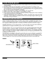
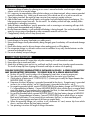
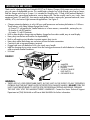
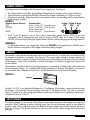
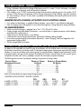
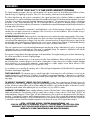
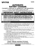
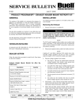
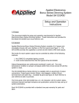
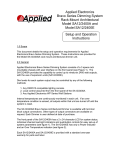
VEC072
START-IT
MANUAL BATTERY CHARGER
™
OWNER’S MANUAL & WARRANTY INFORMATION
6/2 AMP – BATTERY CHARGER FOR 6 AND 12 VOLT DC BATTERIES
1. WORKING IN VICINITY OF A LEAD-ACID BATTERY IS DANGEROUS. BATTERIES
GENERATE EXPLOSIVE GASES DURING NORMAL BATTERY OPERATION. FOR THIS
REASON, IT IS OF UTMOST IMPORTANCE THAT EACH TIME BEFORE USING YOUR
CHARGER, YOU READ THIS MANUAL AND FOLLOW THE INSTRUCTIONS EXACTLY.
2. To reduce risk of battery explosion, follow these instructions and those published
by the battery manufacturer and the manufacturer of any equipment you intend
to use in vicinity of battery. REVIEW CAUTIONARY MARKINGS ON THESE
PRODUCTS AND ON ENGINE.
GENERAL BATTERY SAFETY:
1. Use charger for charging a LEAD-ACID battery only. It is not intended to supply power to a low
voltage electrical system other than in an automotive application. Do not use battery charger for
charging dry-cell batteries that are commonly used with home and portable appliances. These
batteries may burst and cause injury to persons and damage to property.
2. Use of an attachment not recommended or sold by the battery charger manufacturer may result in
a risk of fire, electric shock, or injury to persons.
3. To reduce risk of damage to electric plug and cord, pull by plug rather than cord when
disconnecting charger.
4. An extension cord should not be used unless absolutely necessary. Use of an improper extension
cord could result in a risk of fire and electric shock. If extension cord must be used, make sure:
a.That pins on plug of extension cord are the same number, size, and shape as those of plug
on charger.
b.That extension cord is properly wired and in good electrical condition; and
c. That wire size is AWG #18 (18 gauge) to 100 feet and AWG #16 for distances over 100 feet.
5. Do not operate charger with damaged cord or plug - replace the cord or plug immediately.
6. Do not operate charger if it has received a sharp blow, been dropped, or otherwise
damaged in any way; take it to a qualified service technician.
7. Do not disassemble charger; take it to a qualified service technician when service or repair is required.
Incorrect reassembly may result in a risk of electric shock or fire.
8. To reduce risk of electric shock, unplug charger from outlet before attempting any maintenance or
cleaning. Turning off controls will not reduce this risk.
9. Do not expose charger to rain or snow.
10.Never charge a frozen battery.
• IMPORTANT SAFETY INSTRUCTIONS •
SAVE THESE INSTRUCTIONS This manual contains important safety and operating instructions for battery charger Model VEC072
4140 SW 28TH WAY, FT. LAUDERDALE, FL 33312 • TEL: 945-584-4446 • FAX: 954-584-5556 • TOLL-FREE: 866-584-5504
1
PERSONAL PRECAUTIONS AND SAFETY
1. Someone should be within range of your voice or close enough to come to your aid when you work near
a lead-acid battery.
2. Have plenty of fresh water and soap nearby in case battery acid contacts skin, clothing, or eyes.
3. Wear complete eye protection and clothing protection. Avoid touching eyes while working with a battery.
Acid, acid particles or corrosion may get into eyes. Immediately flood eye with running cold water for at
least 10 minutes and get medical attention immediately.
4. If battery acid contacts skin or clothing, wash immediately with soap and water.
5. NEVER smoke or allow a spark or flame in vicinity of battery or engine.
6. Be extra cautious to reduce risk of dropping a metal tool onto battery. It might spark or short-circuit battery
or other electrical part that may cause explosion.
7. Remove personal metal items such as rings, bracelets, necklaces, and watches when working with a leadacid battery. A lead-acid battery can produce a short-circuit current high enough to weld a ring or the
like to metal, causing a severe burn.
GROUND AND AC POWER CORD CONNECTIONS
Charger should be grounded to reduce risk of electric shock. Charger is equipped with an electric cord
having an equipment grounding conductor and a grounding plug. The plug must be plugged into an outlet
that is properly installed and grounded in accordance with all local codes and ordinances. See figure 1.
DANGER! NEVER alter AC cord or plug provided – if it will not fit outlet, have proper outlet installed by a
qualified electrician. Improper connection can result in the risk of an electric shock.
This battery charger is for use on a nominal 120 volt circuit, has a grounding plug that looks like the plug
illustrated in figure1. A temporary adapter, which looks like the adapter illustrated in figures 1 A and B,
may be used to connect this plug to a two-pole receptacle as shown in figure 1 B, if a properly grounded
outlet is not available. The temporary adapter should be used only until a properly grounded outlet can be
installed by a qualified electrician.
DANGER! Before using adapter as illustrated, be certain that center screw of outlet plate is grounded. The
green-colored rigid ear or tab extending from adapter must be connected to a properly grounded outlet–
make certain it is grounded. If necessary, replace original outlet cover plate screw with a longer screw that
will secure adapter ear or tab to outlet cover plate and make ground connection to grounded outlet.
FIGURE 1
ADAPTER (B)
GROUNDING PIN (A)
2
METAL SCREW
GROUNDING
MEANS
PREPARING TO CHARGE
1. Determine voltage of battery by referring to car owner's manual and make sure that output voltage
selector switch is set at correct voltage.
2. If it is necessary to remove battery from vehicle to charge, or to clean terminals, always remove grounded
terminal from battery first. Make sure all accessories in the vehicle are off, so as not to cause an arc.
3. Clean battery terminals. Be careful to keep corrosion from coming in contact with eyes.
4. Add distilled water in each cell until battery acid reaches level specified by battery manufacturer. This
helps purge excessive gas from cells. Do not overfill. For a battery without cell caps, carefully follow
manufacturer's recharging instructions.
5. Study all battery manufacturers' specific precautions such as removing or not removing cell caps while
charging and recommended rates of charge.
6. Be sure area around battery is well ventilated while battery is being charged. Gas can be forcefully blown
away by using a piece of cardboard or other nonmetallic material such as a fan.
7. Charge battery initially at the 2 Amp (lowest) rate.
CHARGER LOCATION
1. Locate charger as far away from battery as cables permit.
2. Never place charger directly above battery being charged; gases from battery will corrode and damage
charger.
3. Never allow battery acid to drip on charger when reading gravity or filling battery.
4. Do not operate charger in a closed-in area or restrict ventilation in any way. Marine batteries must be
removed and charged on shore.
5. Do not set a battery on top of charger.
DC CONNECTION PRECAUTIONS
1. Connect and disconnect DC output clips only after removing AC cord from electric outlet.
2. Never allow clips to touch each other.
3. Attach clips to battery posts and twist or rock back and forth several times to make a good connection.
This tends to keep clips from slipping off terminals and helps to reduce risk of sparking.
FOLLOW THESE STEPS WHEN BATTERY IS INSTALLED IN VEHICLE. A SPARK NEAR BATTERY
MAY CAUSE BATTERY EXPLOSION. TO REDUCE RISK OF A SPARK NEAR BATTERY:
a. Position AC and DC cords to reduce risk of damage by hood, door, or moving engine part.
b. Stay clear of fan blades, belts, pulleys, and other parts that can cause injury to persons.
c. Check polarity of battery posts. POSITIVE (POS, P, +) battery post usually has larger diameter than
NEGATIVE (NEG, N,-) post.
d. Determine which post of battery is grounded (connected) to the chassis. If negative post is grounded
to chassis (as in most vehicles), see (e). If positive post is grounded to the chassis, see (f).
e. For negative-grounded vehicle, connect POSITIVE (RED) clip from battery charger to POSITIVE (POS,
P, +) ungrounded post of battery. Connect NEGATIVE (BLACK) clip to vehicle chassis or engine block
away from battery. Do not connect clip to carburetor, fuel lines, or sheet-metal body parts. Connect
to heavy gauge metal part of the frame or engine block.
f. For positive-grounded vehicle, connect NEGATIVE (BLACK) clip from battery charger to NEGATIVE
(NEG, N, -) ungrounded post of battery. Connect POSITIVE (RED) clip to vehicle chassis or engine
block away from battery. Do not connect clip to carburetor, fuel lines, or sheet-metal body parts.
Connect to a heavy gauge metal part of the frame or engine block.
g. When disconnecting charger, turn switches to off, disconnect AC cord, remove clip from vehicle
chassis, and then remove clip from battery terminal.
h. See operating instructions for length of charge information.
3
INTRODUCTION AND FEATURES
Thank you for selecting the Vector® Model VEC072 6/2 Battery Charger. With proper care and use, it will
give you years of dependable service. This model battery charger has a high charge rate of up to 6 amps,
and low charge rate of up to 2 amps. It is intended for charging only 12 and 6 volt lead-acid batteries maintenance free, conventional automotive, marine deep cycle - that are usually used in cars, trucks, farm
equipment, boats, RVs and SUVs, lawn mowers and garden tractors, motorcycles, personal watercraft, snowmobiles, ATVs, and various light commercial applications. See Figure 2.
• Charges automotive batteries in only 6-8 hours and lawnmower and motorcycle batteries in 3-8 hours.
Three settings, with sliding Voltage charge Rate Switch:
a) 2 amps: 12 volt motorcycle, smaller batteries as in lawn mowers, snowmobiles, motorcycles, etc.
b) 6 amps: 6 volt DC batteries.
c) 6 amps: 12 volt DC batteries.
• Built-in meter displays charge rate and battery charge level are color-coded, easy-to-read display.
• Heavy-duty transformer and rectifier for dependability
• Built-in self-resetting circuit breaker to protect against short circuits
• Heavy-duty cables and clamps are corrosion-resistant for better connections
• Connect to side or top-mount battery terminals
• Rugged steel case with baked on finish, plus sturdy carry handle
• Ideal for charging during winter season when the starting performance of vehicle batteries is lowered by
cold or extreme weather conditions.
• UL-Listed
3
FIGURE 2
1
4
STARTIT™
1.
2.
3.
4.
AMMETER
BATTERY CLAMPS
HANDLE
VOLTAGE CHARGE
RATE SWITCH
5. GROUNDED PLUG
2
5
WARNING:
• THERE ARE NO USER-SERVICEABLE PARTS IN THIS UNIT. IN THE EVENT OF ANY OPERATING
PROBLEM THAT THE UNIT'S BUILT-IN CIRCUIT PROTECTION CANNOT HANDLE, DO NOT OPEN THE
UNIT. IT MUST BE RETURNED TO VECTOR FOR PROFESSIONAL TESTING AND REPAIR. OPENING
THE UNIT WILL VOID THE MANUFACTURER'S WARRANTY. Contact the Vector Technical Support
Department at (954) 584-4446 or toll-free at 866-584-5504 for further information.
4
CHARGER CONTROLS
The charger control is located on the front panel of the charger unit. See Figure 3.
• The sliding selector switch offers three Voltage/Charge Rates for charging various types of batteries.
• Select the correct switch position BEFORE connecting the charger to a battery or AC power source.
• Selections are made by sliding the switch into the correct position, corresponding with the type of battery
being charged, as follows:
FIGURE 3
SELECTOR SWITCH POSITION
LEFT
CENTER
RIGHT
CHARGING RATE
6 AMP/12 VOLT DC (LARGE BATTERIES)
2 AMP/12 VOLT DC (SMALL BATTERIES,
28 AMP HOUR OR LESS)
6 AMP/6 VOLT DC (LARGE BATTERIES)
6 Amp 2 Amp 6 Amp
12V
12V
6V
• Small 12 volt DC batteries such as those used in motorcycles, garden tractors, ATVs, jet skis, and
snowmobiles can be damaged by high rates of charge. ALWAYS select the 2 Amp/12 Volt setting
(CENTER switch position) to charge this type of battery and for a slower charging time on larger batteries.
WARNING:
If in doubt about battery size, charge at the 2 Amp rate. DO NOT overcharge batteries. ALWAYS ensure
that the selection corresponds to the voltage of the battery being charged.
AMMETER
The ammeter is the colored (red and green) chart on the front of the unit. It displays the current flowing from
the charger to the battery, in amperes. (See Figure 4.) The current when starting to charge a battery will
depend on the battery's percent of charge. The actual current will usually be lower than the current selected
on the charger's switch, unless the battery is severely discharged. As the battery charge level increases, the
current reduces.
The ammeter is intended to show how the charging process is proceeding. It should not be used to determine
the level of battery charge - this should be done using a hydrometer or voltmeter. If the battery vent caps are
not removable, then a voltmeter or load tester is used to determine the charge level of the battery.
FIGURE 4
AMMETER
Typically 12.6 VDC is considered a full charge on a 12 volt battery if the voltage is measured one hour after
the charger is disconnected. During charging, a nominal 12 volt battery can be 13.6 volts or somewhat
higher, so it needs to rest after charging to measure actual state of charge. For a 6 volt battery, full charge is
considered to be at 6.3 volts DC.
CIRCUIT BREAKER
This battery charger has an internal self-resetting circuit breaker that protects the charger from temporary
overloads. When it operates it makes a clicking sound. You will see the ammeter reduce to zero when the
breaker is open. After a cool-down period, the breaker will automatically close and the ammeter will show a
high rate of charge. If the breaker continues to cycle every few minutes, reduce charge rate or discontinue
charging.
5
PRE-CHARGE ACTIVATION:
CAUTION: Be aware that a fully discharged battery will also cause a low ammeter reading. Attempting
pre-charge activation of a fully discharged battery may cause explosion - make sure that battery really is
discharged, before using this procedure. Apply a load to the battery to check if it is charged or
discharged. Pre-charge activation is the term for the time it takes before a battery begins to accept a
measurable rate of charge - it can be as long as 4-8 hours from the time the charging process begins.
Pre-charge activation is indicated if the ammeter reading is zero and a hydrometer or voltmeter reading
shows that the battery is fully discharged.
NOTE: The newer, high-calcium-type 12 volt DC batteries may need pre-charge activation if their charge has
been allowed to drop to a very low level. When deeply discharged, this type of battery will provide only
a very low voltage output and will draw less than 1 amp during the recharging process, until activated.
CHARGING IF BATTERY IS INSTALLED IN A VEHICLE:
It is normal for a battery to get warm during charging. If a battery is getting hot, reduce charge rate or
discontinue charging.
a) Set charger voltage selector switch to appropriate setting. If in doubt, refer to vehicle manufacturers'
recommendations.
b) Check polarity of battery posts - For top-mounted battery connectors, the Positive post (marked
POS, P, +) usually has a larger diameter than the Negative battery post (marked NEG, N, -). For sidemounted battery connectors, the terminals are marked Positive -red and Negative - black.
c) Attach charger clamps to battery connections, as follows, ensuring a good connection:
NEGATIVE-GROUNDED VEHICLE: Connect the POSITIVE (RED) charger clamp to the POSITIVE (POS, P,
+) ungrounded battery terminal. Then, connect the NEGATIVE (BLACK) charger clamp to the vehicle chassis,
or the engine block (away from the battery). DO NOT connect the clamp to the carburetor, fuel lines, or
sheet-metal body parts: connect only to a heavy gauge metal part of the frame or engine block.
NOTE: NEGATIVE-GROUNDED type systems are the most common in today's Vehicles. If in doubt, check
vehicle manufacturers' recommendations.
POSITIVE-GROUNDED VEHICLE: Connect the NEGATIVE (BLACK) charger clamp to the NEGATIVE
(NEG, N, -) ungrounded battery post. Then, connect the POSITIVE (RED) battery clamp to the vehicle chassis
or engine part (away from the battery). DO NOT connect the clamp to the carburetor, fuel lines, or sheetmetal body parts: connect only to a heavy gauge, stable metal part of the frame or engine block.
NOTE: If there is any problem connecting the charger clamps to the battery terminals, contact the Vector
Technical Support Department at (954 - 584-4446) for assistance.
d) Plug battery charger power cord into grounded AC power outlet and refer to Appendix A at the end
of this document for approximate charging times.
NOTE: Use of Extension Cords
If it is necessary to use an extension cord, as is often the case, observe the following important safety
information:
• Before using any extension cord, ensure that the wire size is at least 18 AWG or larger and 16 AWG
for longer than 100 feet.
• Use only a good quality, good condition, UL-approved extension cord, and ALWAYS connect charger to
the extension cord before plugging the extension cord into a 110/120 volt AC power outlet. The use of a
poor quality extension cord or one that is not in good repair could cause fire and/or electric shock.
• Use a three-wire extension cord with a 3-prong plug and 3-conductor socket.
e) When charging is completed, disconnect cables and clamps in reverse order from which they were
connected.
6
CHARGING IF BATTERY IS OUTSIDE OF VEHICLE:
a) Check polarity of battery posts- For top-mounted battery connectors, the positive post marked POS,
P, +) usually has a larger diameter than the Negative battery post (marked NEG, N, -). For sidemounted battery connections the Positive terminal is red, the Negative terminal is black.
b) Attach a 24 inch (minimum length) 6 AWG insulated battery cable to the Negative battery post
(marked NEG, N, -).
c) Connect the Positive (RED) battery clamp to the Positive battery connector (marked POS, P, + or red).
d) Stand as far back from battery as possible, and do not face battery when making final connection.
e) Carefully connect the Negative (BLACK) charger clamp to the free end of the battery cable connected
to the negative terminal. Connect the charger's power cord to a grounded 110/120 volt AC power
outlet, and refer to the next section for approximate charging times.
f) When charging is completed, disconnect cables and clamps in reverse order from which they were
connected.
CHARGING TIMES
To calculate the approximate charging time required to fully charge a battery, it is necessary to determine
percent of battery charge. Batteries less than 10 volts (or 5 volts for a 6 volt battery) may be considered as
discharged. To estimate charging time for a discharged battery, divide the AH rating of the battery by the
charge rate selected. This is the number of hours required to recharge the battery. For example, a 50 AH (12
volt) battery is discharged (10 volts). How long should it be charged at the 6 Amp rate? Divide the 50 AH by
6 AH. The answer is approximately 8 hours. Always round up the charge time by 25% to ensure full charge.
So the answer is approximately 10 hours. In most cases, battery recharge times will vary depending on the
age and condition of the battery. Smaller batteries should be charged at the lower rate (2 Amps) and add an
extra hour to charge time. If more detail is required, refer to Appendix A at the end of this document.
NOTE: Batteries that have a 25% (or less) charge level, are subject to freezing, and should be charged as
soon as possible to prevent freezing in temperatures 0°C/32°F or below.
CARE AND MAINTENANCE
With only minimal maintenance, the Vector 6/2 Battery Charger will deliver years of dependable service.
Follow these simple steps to maintain the charger in optimum condition:
• After each use, clean the battery charger clamps - be sure to remove any battery fluid that will cause
corrosion of the clamps.
• Clean the outside case of the charger with a soft cloth and, if necessary, mild soap solution.
• Keep the charger cords loosely coiled during storage to prevent damage to the cords. Do not use the
charger if cords or clamps have been damaged in any way - call Vector Technical Support Department at
866-584-5504 for details on replacing cords and clamps.
TROUBLESHOOTING SLOW RATES OF CHARGE
Very Cold Battery
If the battery to be charged is extremely cold (in temperatures less than freezing - 0ºC/32ºF) it cannot accept
a high rate of charge, so the initial charge rate will be slow. The rate of charge will increase as the battery
warms.
Sulfated Battery
When batteries are left in a discharged state for a long period of time, they become "sulfated". Sulfated
batteries cannot accept a high rate of charge since the internal plates are coated with lead sulphate. To see if
a battery in this condition can be "saved", take it to a service station or battery distributor for professional
evaluation and/or service.
Short-circuited Battery
If the battery being charged has been short-circuited, the ammeter will show that the battery has zero charge
level, and that the charger is operating at peak amperage. If, after 5 minutes charging time, the ammeter
reading has not decreased, unplug the charger and discontinue the charging process.
7
SLOW RATES OF CHARGE – CONTINUED
• Using a voltmeter, determine the voltage of the battery and if it is under 12 volts, the battery is probably
beyond repair or recharging, and will need to be replaced.
• If the voltage is over 12 volts, reconnect the charger and resume the charging process for another 15-20
minutes. If, after that time, the ammeter still has not moved towards a lower reading, repeat the voltmeter
test. If the reading is still over 12 volts, there is a problem with the battery that requires professional service
or replacement.
AMMETER DISPLAYS A READING, BUT BATTERY IS NOT ACCEPTING CHARGE
• First, make sure that battery is capable of being charged - ensure that it is not sulfated or damaged.
• Refer to Charging Times and Appendix A to ensure that enough time is being allowed to charge the battery.
NO AMMETER READING
• Make sure that the charger is plugged into a "live" 110/120 volt AC outlet.
• Unplug charger and check battery connections - ensure that there is a good connection with the battery
terminal and/or vehicle chassis.
• Check to be sure that the battery is not sulfated.
• Check that the correct charge rate has been selected for the battery being charged.
• Ensure that enough charging time has been allowed for - check Charging Times and Appendix A for
approximate charging times.
• See Pre-charge Battery Activation
APPENDIX A ESTIMATING BATTERY CHARGE TIME - VENT CAP BATTERIES
For batteries with removable vent caps fill the top of each battery cell with distilled water to the level recommended
by the battery manufacturer, but do not overfill. To calculate the approximate charging time required to fully charge
a battery, it is necessary to determine the specific gravity (or percent of battery charge) using a hydrometer. Use this
technique if battery vent caps can be removed. Check each cell. If there is one cell with a very low specific gravity
compared to the other cells, there is probably a shorted cell in the battery. Replace the battery.
The following chart converts hydrometer readings into percent of charge values.
SPECIFIC GRAVITY
PERCENT OF CHARGE
PERCENT OF CHARGE NEEDED
(HYDROMETER READING)
IN BATTERY
BY BATTERY
1.265 ..................................................... 100% ................................. 0%
1.225 ...................................................... 75% ................................. 25%
1.190 ...................................................... 50% ................................. 50%
1.155 ...................................................... 25% ................................. 75%
1.120 ....................................................... 0% ................................. 100%
Refer to the chart below for approximate charging times.
CHARGER SWITCH SETTING % BATTERY CHARGE:
75%
50%
25%
0%
6 AMPS/ 6 VOLTS ..................................3.75 HRS ..... 7 HRS .......... 10 HRS 1 ..... 12.5 HRS
2 AMPS/12 VOLTS .................................6.5 HRS ....... 12 HRS ........ 18 HRS ........ 23 HRS
6 AMPS/12 VOLTS .................................2.3 HRS ....... 4.6 HRS ....... 7 HRS .......... 9 HRS
8
APPENDIX B – SPECIFICATIONS
Height ............................................................................................. 4.5 inches (11.43 cm)
Width ............................................................................................. 7.5 inches (19.05 cm)
Depth .............................................................................................. 5.1 inches (12.95 cm)
Weight ............................................................................................ 5 lbs (2.26 kg)
Internal protection ............................................................................ self-resetting breaker
Input voltage.................................................................................... 120 VAC 60 Hz, 1.3 amperes.
Convenience features ....................................................................... Handle
9
WARRANTIES:
VECTOR "GOLD SEAL" 2/4 YEAR LIMITED WARRANTY PROGRAM
This limited warranty program is the only one that applies to this product, and it sets forth all the responsibilities of Vector
Manufacturing, Ltd., regarding this product. There is no other warranty, other than those described herein.
This Vector Manufacturing, Ltd. product is warranted, to the original purchaser only, to be free of defects in materials and
workmanship for two years from the date of purchase without additional charge. This warranty may be extended to four years
from date of purchase by paying an Extended Warranty fee (see below). The warranty does not extend to subsequent
purchasers or users. Vector Manufacturing, Ltd. will not be responsible for any amount of damage in excess of the retail
purchase price of the product under any circumstances. Incidental and consequential damages are specifically excluded from
coverage under this warranty.
This product is not intended for commercial or rental application, only a 90 day warranty will apply in this instance. This
warranty does not apply to accessories or damage to units from misuse or incorrect installation. Misuse includes wiring or
connecting to improper polarity power sources.
RETURN/REPAIR POLICY: Defective products, other than accessories, may be returned postage prepaid to Vector Manufacturing. Any defective product, other than accessories, that is returned to Vector Manufacturing within 30 days of the date
of purchase will be replaced free of charge. If such a product is returned more than 30 days but less than two years from the
purchase date, Vector Manufacturing will repair the unit or, at its option, replace it free of charge. If The Extended Warranty
was activated, this repair or replacement period extends to four years from the purchase date.
If the unit is repaired, new or reconditioned replacement parts may be used, at Vector Manufacturing's option. A unit may be
replaced with a new or reconditioned unit of the same or comparable design. The repaired or replaced unit will then be
warranted under the terms of the remainder of the warranty period.
The customer is responsible for the shipping charges on all returned items. During the warranty period, Vector Manufacturing,
Ltd. will be responsible for the return shipping charges.
LIMITATIONS: This warranty does not cover accessories, bulbs, fuses and batteries, defects resulting from normal wear and
tear (including chips, scratches, abrasions, discoloration or fading due to usage or exposure to sunlight), accidents, damage
during shipping to our service facility, alterations, unauthorized use or repair, neglect, misuse, abuse, failure to follow
instructions for care and maintenance, fire, flood, and Acts of God.
If your problem is not covered by this warranty, call our Technical Support Department at (954) 584-4446 for general repair
information and charges if applicable.
STATE LAW RIGHTS: This warranty gives you specific legal rights. Some states do not allow limitations on how long an
implied warranty lasts or the exclusion or limitation of incidental or consequential damages, so the exclusions or limitations
stated herein may not apply. This warranty gives the purchaser specific legal rights; other rights, which vary from state to state,
may apply.
TO REQUEST WARRANTY SERVICE FOR THIS PRODUCT: Contact Vector Manufacturing Technical Support by
telephone, fax or mail. We suggest that you keep the original packaging in case you need to ship the unit. When returning a
product, include your name, address, phone number, dated sales receipt (or copy), and a description of the reason for return
and product serial number. After replacing the unit, we will return it to you within four weeks.
WARRANTY ACTIVATION: Please complete Warranty Activation Card and mail to Vector Manufacturing. If activating
Additional Extended Two Year Warranty, (total four years) enclose check or money order for $20.00 Enter "VEC072" as
Model and Battery Charger as "Product Type". All Vector Manufacturing, Ltd. products must be registered within (30) days of
purchase. To activate this warranty, mail completed registration form, a copy of the original sales receipt and required fee
(if activating extended warranty) to: All Vector Manufacturing, Ltd. products must be registered within (30) days of purchase
to activate this warranty. Mail the completed registration form, along with a copy of the original sales receipt to:
ATTN.: CUSTOMER SERVICE / VECTOR MANUFACTURING, Ltd.
4140 SW 28th Way, Ft. Lauderdale, FL 33312 • 954-584-4446 • Fax: 954-584-5556
WARRANTY MUST BE PURCHASED WITHIN 30 DAYS OF PRODUCT PURCHASE DATE.
WARRANTY IS NON-TRANSFERABLE AND NON-REFUNDABLE.
10
11
© 2002 VECTOR MANUFACTURING, Ltd. • FT. LAUDERDALE, FL 33312 • MADE IN CHINA
12