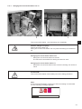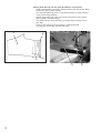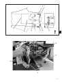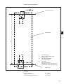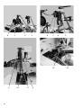
1
Manual, complete
745 - 34 - 2
Sewing unit for runstitching of piped flap
and welt pocket openings and pocket corners
Working methods: A, B, D, F
Operating Instructions
1
Installation Instructions
2
Service Instructions
3
Instructions for Programming DAC
4
Postfach 17 03 51, D-33703 Bielefeld • Potsdamer Straße 190, D-33719 Bielefeld
Telefon + 49 (0) 5 21 / 9 25-00 • Telefax + 49 (0) 5 21 / 9 25 24 35 • www.duerkopp-adler.com
Ausgabe / Edition:
08/2007
Änderungsindex
Rev. index: 01.0
Printed in Federal Republic of Germany
Teile-Nr./Part.-No.:
0791 745181
745 - 34 - 2
Manual, complete
Contents
Operating Instructions
Installation Instructions
Service Instructions
Instructions for Programming DAC
Interconnection-diagram
9870 745154 B
9890 745002 B
Pneumatic circuit plan
9770 745005
All rights reserved.
Property of Dürkopp Adler AG and copyrighted. Reproduction or publication of the content in
any manner, even in extracts, without prior written permission of Dürkopp Adler AG, is
prohibited.
Copyright © Dürkopp Adler AG - 2007
Foreword
This instruction manual is intended to help the user to become familiar
with the machine and take advantage of its application possibilities in
accordance with the recommendations.
The instruction manual contains important information on how to
operate the machine securely, properly and economically. Observation
of the instructions eliminates danger, reduces costs for repair and
down-times, and increases the reliability and life of the machine.
The instruction manual is intended to complement existing national
accident prevention and environment protection regulations.
The instruction manual must always be available at the machine/sewing
unit.
The instruction manual must be read and applied by any person that is
authorized to work on the machine/sewing unit. This means:
–
–
–
Operation, including equipping, troubleshooting during the work
cycle, removing of fabric waste,
Service (maintenance, inspection, repair) and/or
Transport.
The user also has to assure that only authorized personnel work on the
machine.
The user is obliged to check the machine at least once per shift for
apparent damages and to immediatly report any changes (including the
performance in service), which impair the safety.
The user company must ensure that the machine is only operated in
perfect working order.
Never remove or disable any safety devices.
If safety devices need to be removed for equipping, repairing or
maintaining, the safety devices must be remounted directly after
completion of the maintenance and repair work.
Unauthorized modification of the machine rules out liability of the
manufacturer for damage resulting from this.
Observe all safety and danger recommendations on the machine/unit!
The yellow-and-black striped surfaces designate permanend danger
areas, eg danger of squashing, cutting, shearing or collision.
Besides the recommendations in this instruction manual also observe
the general safety and accident prevention regulations!
General safety instructions
The non-observance of the following safety instructions can cause
bodily injuries or damages to the machine.
1. The machine must only be commissioned in full knowledge of the
instruction book and operated by persons with appropriate training.
2. Before putting into service also read the safety rules and
instructions of the motor supplier.
3. The machine must be used only for the purpose intended. Use of
the machine without the safety devices is not permitted. Observe all
the relevant safety regulations.
4. When gauge parts are exchanged (e.g. needle, presser foot, needle
plate, feed dog and bobbin) when threading, when the workplace is
left, and during service work, the machine must be disconnected
from the mains by switching off the master switch or disconnecting
the mains plug.
5. Daily servicing work must be carried out only by appropriately
trained persons.
6. Repairs, conversion and special maintenance work must only be
carried out by technicians or persons with appropriate training.
7. For service or repair work on pneumatic systems, disconnect the
machine from the compressed air supply system (max. 7-10 bar).
Before disconnecting, reduce the pressure of the maintenance unit.
Exceptions to this are only adjustments and functions checks made
by appropriately trained technicians.
8. Work on the electrical equipment must be carried out only by
electricians or appropriately trained persons.
9. Work on parts and systems under electric current is not permitted,
except as specified in regulations DIN VDE 0105.
10. Conversion or changes to the machine must be authorized by us
and made only in adherence to all safety regulations.
11. For repairs, only replacement parts approved by us must be used.
12. Commissioning of the sewing head is prohibited until such time as
the entire sewing unit is found to comply with EC directives.
13. The line cord should be equipped with a country-specific mains
plug. This work must be carried out by appropriately trained
technicians (see paragraph 8).
It is absolutely necessary to respect the safety
instructions marked by these signs.
Danger of bodily injuries !
Please note also the general safety instructions.
Index
Page:
Part 1: Operating Instructions 745-34-2
(Edition 08/2007)
1.
1.1
1.2
1.3
1.4
Product Description
Description of proper use .
Brief description . . . . . .
Technical data . . . . . . .
Optional equipment . . . .
2.
2.1
2.2
2.3
2.4
2.5
2.6
2.7
2.8
2.9
2.10
2.11
2.11.1
2.11.2
2.12
2.13
2.14
2.15
2.15.1
2.15.2
2.15.2.1
2.15.2.2
2.15.3
Operation
Swinging the folding station aside. . . . . . . . . . . . . . . . . . . . . . . . . . . . . .
Pushing the covering hood back and removing the fabric sliding sheet . . . . . . .
Tilting the machine head up . . . . . . . . . . . . . . . . . . . . . . . . . . . . . . . . .
Needles and threads . . . . . . . . . . . . . . . . . . . . . . . . . . . . . . . . . . . . .
Threading the needle thread . . . . . . . . . . . . . . . . . . . . . . . . . . . . . . . . .
Winding the hook thread . . . . . . . . . . . . . . . . . . . . . . . . . . . . . . . . . . .
Remaining thread monitor . . . . . . . . . . . . . . . . . . . . . . . . . . . . . . . . . .
Changing the bobbins . . . . . . . . . . . . . . . . . . . . . . . . . . . . . . . . . . . . .
Thread tension . . . . . . . . . . . . . . . . . . . . . . . . . . . . . . . . . . . . . . . . .
Stacking control . . . . . . . . . . . . . . . . . . . . . . . . . . . . . . . . . . . . . . . .
Slanted pocket corners . . . . . . . . . . . . . . . . . . . . . . . . . . . . . . . . . . . .
Swinging the corner knife station out / in . . . . . . . . . . . . . . . . . . . . . . . . .
Setting the corner knives (Manual corner knife station) . . . . . . . . . . . . . . . . .
Reference position - Starting the sewing cycle - Quick stop . . . . . . . . . . . . . .
Flap and piping projection . . . . . . . . . . . . . . . . . . . . . . . . . . . . . . . . . .
Piping strip length . . . . . . . . . . . . . . . . . . . . . . . . . . . . . . . . . . . . . . .
Working methods. . . . . . . . . . . . . . . . . . . . . . . . . . . . . . . . . . . . . . . .
Working method A (Production of trousers) . . . . . . . . . . . . . . . . . . . . . . . .
Sewing with flap . . . . . . . . . . . . . . . . . . . . . . . . . . . . . . . . . . . . . . . .
Sewing without light barrier . . . . . . . . . . . . . . . . . . . . . . . . . . . . . . . . .
Sewing with light barrier . . . . . . . . . . . . . . . . . . . . . . . . . . . . . . . . . . .
Working method A (Production of jackets)
Piped pockets, manual positioning of piping strip, flaps and other additional parts
Working method B
Piped pockets, automatic feed of the piping strip, without/with incision of the
piping ends . . . . . . . . . . . . . . . . . . . . . . . . . . . . . . . . . . . . . . . . . . .
Working method D
Breast welt pockets, automatic feed and matching of the breast welt . . . . . . . .
Working method F
Piped pockets, automatic feed of the piping strip,
incision of the piping ends, matching and feed of the flap . . . . . . . . . . . . . . .
Folder monitoring . . . . . . . . . . . . . . . . . . . . . . . . . . . . . . . . . . . . . . .
Functions and operation of the optional equipment . . . . . . . . . . . . . . . . . . .
Automatic incision device for piping ends . . . . . . . . . . . . . . . . . . . . . . . . .
Downholder, pocket bag and waistband clamp . . . . . . . . . . . . . . . . . . . . . .
Feeding devices for flaps, pocket bags etc. . . . . . . . . . . . . . . . . . . . . . . . .
2.15.4
2.15.5
2.15.6
2.15.7
2.16
2.16.1
2.16.2
2.16.3
.
.
.
.
.
.
.
.
.
.
.
.
.
.
.
.
.
.
.
.
.
.
.
.
.
.
.
.
.
.
.
.
.
.
.
.
.
.
.
.
.
.
.
.
.
.
.
.
.
.
.
.
.
.
.
.
.
.
.
.
.
.
.
.
.
.
.
.
.
.
.
.
.
.
.
.
.
.
.
.
.
.
.
.
.
.
.
.
.
.
.
.
.
.
.
.
.
.
.
.
.
.
.
.
.
.
.
.
.
.
.
.
.
.
.
.
.
.
.
.
.
.
.
.
.
.
.
.
.
.
.
.
.
.
.
.
.
.
.
.
.
.
.
.
.
.
.
.
.
.
.
.
.
.
.
.
5
5
7
8
.
.
.
.
.
.
.
.
.
.
.
.
.
.
.
.
.
.
.
.
.
.
.
.
.
.
.
.
.
.
.
.
.
.
.
.
.
.
.
.
.
.
.
.
.
.
.
.
.
.
.
.
.
.
.
.
.
.
.
.
.
.
.
.
.
.
.
.
.
.
.
.
.
.
.
.
.
.
.
.
.
.
.
.
.
.
.
.
.
.
.
.
.
.
.
.
.
.
.
.
.
.
.
.
.
11
12
15
16
19
20
21
22
24
25
26
27
28
30
31
32
33
34
37
37
39
. . . . .
40
. . . . .
46
. . . . .
56
.
.
.
.
.
.
62
66
67
67
70
71
.
.
.
.
.
.
.
.
.
.
.
.
.
.
.
.
.
.
.
.
.
.
.
.
1
Index
Page:
2.16.4
2.16.5
2.16.6
2.16.7
2.16.8
2.16.9
2.16.10
2.16.11
2.16.12
2.16.13
2.16.14
Throw-over stacker . . . . . . . . . . . . . . . . . . .
Roll-off device . . . . . . . . . . . . . . . . . . . . . .
Blow-out device . . . . . . . . . . . . . . . . . . . . .
Bundle clamp and roll-off device . . . . . . . . . . .
Tape feed and automatic cutting. . . . . . . . . . . .
Endless zipper device . . . . . . . . . . . . . . . . . .
Vacuum device . . . . . . . . . . . . . . . . . . . . . .
Working method B with set of parts “Pocket bag on
Zipper feeders for method B . . . . . . . . . . . . . .
Set of parts “Shaped guide Lining loop triangle” for
Smoother for 745-34-2 A and B . . . . . . . . . . . .
. . . . . .
. . . . . .
. . . . . .
. . . . . .
. . . . . .
. . . . . .
. . . . . .
flap” . .
. . . . . .
745-34-2
. . . . . .
. . . . . . .
. . . . . . .
. . . . . . .
. . . . . . .
. . . . . . .
. . . . . . .
. . . . . . .
. . . . . . .
. . . . . . .
methods B
. . . . . . .
. . . .
. . . .
. . . .
. . . .
. . . .
. . . .
. . . .
. . . .
. . . .
and F
. . . .
.
.
.
.
.
.
.
.
.
.
.
.
.
.
.
.
.
.
.
.
.
.
.
.
.
.
.
.
.
.
.
.
.
.
.
.
.
.
.
.
.
.
.
.
.
.
.
.
.
.
.
.
.
.
.
.
.
.
.
.
.
.
.
.
.
.
.
.
.
.
.
.
.
.
.
.
.
72
74
75
76
77
81
82
83
86
87
88
3.
3.1
3.2
Maintenance
Cleaning . . . . . . . . . . . . . . . . . . . . . . . . . . . . . . . . . . . . . . . . . . . . . . . . . .
Weekly lubrication . . . . . . . . . . . . . . . . . . . . . . . . . . . . . . . . . . . . . . . . . . . .
89
92
1.
1.1
Product description
Description of proper use
The 745-34-2 is a sewing unit which can properly be used for sewing
light to medium-weight material. Such material is, as a rule, material
made of textile fibres or leather. These materials are used in the
garment industry.
In general only dry material should be sewn on this machine. The
material must not contain any hard objects.
The seam is generally made with core thread, polyester fibre
or cotton threads.
The dimensions for needle and hook threads can be taken from the
table in chapter 2.4.
Before using any other threads it is necessary to estimate the
consequential dangers and to take the respective safety measures, if
required.
This sewing unit must only be installed and operated in dry and
well-kept rooms. If the sewing unit is used in other rooms, which are
not dry and well-kept, further measures to be agreed upon may
become necessary (see EN 60204-31 : 1999).
We, as a manufacturer of industrial sewing machines, assume that at
least semi-skilled operating personnel will be working on our products
so that all usual operations and, where applicable, their risks are
presumed to be known.
1.2
1
Brief description
The Dürkopp Adler 745-34-2 is a sewing unit for automatic
runstitching of piped, flap and welt pocket openings with rectangular or
slanted pocket corners.
The slanted pocket corners result from the seam offset of the two seam
rows. At the seam beginning and seam end it is possible to sew with
different slants.
Dependent on the working method different feeding devices, corner
knife stations and optional equipment are used.
Machine head
– Twin needle lockstitch version
– Needle bars can be switched separately or together
– Large vertical hooks
– Externally driven center knife, speed and circuit timing
programmable
– Thread trimming device for needle and hook threads
– Needle thread monitor
– Photoelectric remaining thread monitor for the hook threads
– Sewing drive as DC direct drive
5
Step motors for the material feed and the length adjustment of the
corner cutting device
The step motor technology results in short machine times and
guarantees an absolutely precise corner incision.
Thus, it contributes to a pocket quality as yet unequalled and combined
with high productivity.
New generation of “DAC III” controls (DÜRKOPP ADLER Control)
The graphic user guidance exclusively occurs via internationally
comprehensible symbols and text lines in the corresponding language.
The various symbols are combined in groups within the menu structure
of the sewing and test programs.
The ease of use makes short training times possible.
The user can combine 99 freely programmable pocket programs with
up to 20 seam patterns.
20 pocket sequences can be called up.
Every pocket sequence can be combined of up to 8 pocket programs in
any order whatever.
All slants suitable for practical application can be programmed by the
operator at the touch of a button.
The time-consuming adjustment of the corner knives and the tiresome
programming of seam offsets are not required.
The comprehensive test and monitoring system MULTITEST is
integrated in the DAC.
A microcomputer does the control tasks, monitors the sewing cycle and
signals operating faults and malfunctions on the display.
Optional equipment
By means of a flexible system of optional equipment the sewing unit
can be equipped optimally and economically corresponding to the
respective application.
See chapter 1.4 (Equipment of the 745-34-2).
Sewing equipment and folders
Data concerning the sewing equipment and folders for the various
applications can be taken from the Equipment Sheets of cl. 745-34-2.
Please direct your enquiries to the DÜRKOPP-ADLER sales offices.
6
1.3
Technical data
Machine head:
Needle system:
Needle distance:
Needle size:
Class 0246 992002
2134-85
10, 12, 14, 16, 20, 24, 26, 30 mm
Nm 80 to Nm110
Threads:
see table chapter 2.4
Stitch type:
Twin needle lockstitch
Speed:
min. 2000 rpm
max. 3000 rpm
min. 2.0 to 3.0 mm
Stitch length:
Number of stitches/condensed
stitches:
Number of stitches/bartack
stitch:
Stitch length condensed
stitches / bartack:
0.5 - 3.0 mm
Pocket length:
Seam offset:
max. 220 mm
max. + /- 13 mm
Operating pressure:
Air consumption:
6 bar
approx. 6 NL per work cycle
Rated voltage:
3 x 230 / 400 V / 50/60 Hz
1 - 10 stitches
0 - 5 stitches
1
Rated load:
Machine with
vacuum blower
0,8 KW
Machine without
vacuum blower
0,5 KW
Dimensions:
Working height:
1540 x 925 x 1200 mm (L x W x H)
790...1100 mm
(upper edge of table top)
Weight:
280 kg
Rated noise level:
LC = 81 dB (A)
Workstation-specific emission value
according to DIN 45635-48-B-1
Stitch length:
2.5 mm
Seam length:
180 mm
Speed:
2750 rpm
Material:
double fabric
240 g/m 2
Measuring point according to DIN
4895 Part 1
X = 600 mm Y = 0 mm Z = 300 mm
7
1.4
8
Optional equipment
Order No.
Optional equipment
A
B
0745 597514
Downholder- pocket bag clamp
Downholder for smoothing the fullness
caused by darts as well as a
clamping device for pocket bags
X
X
0745 597524
Waistband clamp
For smoothing the fullness.
Only possible in conjunction with 0745 597514
X
X
0745 597544
Endless zipper
Scissors with roll-off device for endless zippers
without slider
X
0745 597554
Throw-over stacker
To be positioned near the machine for stacking to the
side or to the back.
Furthermore, this throw-over stacker is equipped with
an easy-to-operate height adjustment and
a swivel device.
X
X
0745 597604
Blow-out device
For blowing the finished workpieces out
X
X
0745 597614
Shaped guide “Lining loop triangle”
In case of inside pockets the lining loop triangle
is fed automatically.
X
0745 597674
Table extension (large)
The table extension required for the working method
with bundle clamp carriage
X
0745 597684
Table extension (small)
Table extension to be used for stacking to the side
X
X
0745 597694
Bundle clamp
This includes the required large table extension
X
X
0745 597764
Right zipper feeder
In conjunction with feeding device 0745 517574
For cut-to-length zippers,
without slider, total width 24 mm, chain width
approx. 4 mm, in case of ready-made pocket chain
inside.
X
0745 597774
Left zipper feeder
In conjunction with feeding device 0745 517564
For cut-to-length zippers,
without slider, total width 24 mm, chain width
approx. 4 mm, in case of ready-made pocket chain
inside.
X
0745 597784
Right zipper feeder
In conjunction with feeding device 0745 517574
For cut-to-length zippers,
without slider, total width 24 mm, chain width
approx. 4 mm, in case of ready-made pocket chain
inside.
X
0745 597794
Left zipper feeder
In conjunction with feeding device 0745 517564
For cut-to-length zippers,
without slider, total width 24 mm, chain width
approx. 4 mm, in case of ready-made pockets chain
inside.
X
D
F
X
X
X
X
X
Order No.
Optional equipment
A
B
D
F
0745 597824
Smoother for the 745-34-2 A/B
The smoother has the purpose to smooth the finished
workpiece held by the bundle clamp. Only in
combination with the table extension 0745 597674
and the roll-off device 0745 597954.
X
X
0745 597874
Set of parts “Pocket bag on flap” NA 10 and 12
for the simultaneous attaching of two pocket bag
halves and flap. Combination only in conjunction with
equipment E 3103 or E 3503 for NA 10
as well as E 3107 or E 3507 for NA 12.
0745 597884
Set of parts “Pocket bag / Piped pocket”
for the blowing of the pocket bag or the piping pocket
with equipment E 2604 or E 2606.
Use only in combination with the clamp K19.
X
0745 597934
Three-pack lasers
Add-on kit: for expanding the existing 5 laser marking
lamps to a maximum of 8 laser marking lamps.
(With the working method F, the standard equipment
includes 8 laser marking lamps).
X
X
X
X
0745 597944
Electromotoric tape feed/Automatic cutting
Automatic feeding and cutting of a
reinforcement strip pulled from a roll. Start time and
cutting time can be programmed
corresponding to the pocket.
X
X
X
X
0745 597954
Roll-off device
It is used to for transporting short pieces into the
stacker or to eject the pieces to be processed.
The speed and the working cycle of the roll-off device
can also be programmed.
X
X
X
X
0745 597964
Vacuum (side channel compressor)
For an accurate positioning of the material when
no in-house vacuum unit is available.
The side channel compressor can be used with the
basic unit.
X
X
X
X
0797 003031
Pneumatic connection package
Connection hose to the pneumatic supply line
with the appropriate couplings.
X
X
X
X
0745 517564
Automatic feeding, left 180 - 220 mm
For the automatic feeding of piping strips and
additional parts.
X
0745 517574
Automatic feeding, right 180 - 220 mm
For the automatic feeding of piping strips and
additional parts.
X
0745 598054
Kit second light barrier
X
1
X
9
2
10
1
2.
2.1
Operation
Swinging the folding station aside
For operations at the sewing point (threading the needle threads,
needle change etc.) the whole folding station with folder and light
barriers can be swung to the right.
– Swing the complete folding station 1 with folder
to the right.
Note:
With the sewing unit switched on, a safety message
appears on the screen of the control panel.
Folding station swung out
1
–
The sewing point is freely accessible.
Swinging the folding station back
– Swing the folding station back.
ATTENTION!
After being swung back the folding station must lock
in the catch 2.
11
2.2
Pushing the covering hood back and removing the fabric sliding sheets
Caution: Danger of injury!
Switch the main switch off.
Push the covering hood back and remove the fabric sliding sheet only
with the sewing unit switched off.
–
Switch the main switch off
1
For a better accessibility of the feeding clamps the covering hood can
simply be displaced.
Pushing the covering hood back
– Push the covering hood 1 to the left.
The feeding clamps are accessible.
– Push the covering hood 1 to the right again until you hear it
snapping in.
12
2
1
1
3
For changing the hook thread bobbins:
– Lift the fabric sliding sheet 2 in the area of pin 1 and swing it to the
left.
For a complete removal (for maintenance and adjusting operations):
– Lift off the fabric sliding sheets at the pin 3.
13
1
6
14
3
4
5
2.3
Tilting the machine head up
For maintenance work the machine head can be tilted up.
For this purpose the transport carriage must be in its rear end position.
Caution: Danger of injury!
Switch the main switch off.
Tilting the machine head up.
– Remove the covering hood 1.
For this purpose lift the covering hood at the front so that the catch
is released. Carefully lift the covering hood upwards.
– Swing the folding station 3 out by 90°.
– Swivel the locking lever 4 up.
– Lift the left fabric sliding sheet 6 at the front and swing it to the left.
– Lift the machine head in the area of head cover 5 and tilt it up
carefully.
Pawl 2 snaps in additionally.
The space under the machine table is accessible for cleaning now.
1
Swinging the machine head back
– Hold the machine head tight in the area of head cover 5.
– Release the pawl 2.
– Swing the machine head back carefully.
Caution: Danger of breakage!
Hold the machine head tight until it is at rest completely.
–
–
–
Insert the fabric sliding sheets.
Swivel the locking lever 4 down.
Swing the folding station 3 back and let it catch with the locking
lever.
Put on the covering hood 1 and let it catch again.
–
2
15
2.4
Needles and threads
Needle system:
Recommended
needle size:
2134-85
Nm 90 for thin material
Nm 100 for medium-weight material
Nm 110 for heavy-weight material
High sewing security and good sewability are achieved with the
following core threads:
– Two-ply polyester endless polyester core-spun
(e.g. Epic Poly-Poly, Rasant x, Saba C, ...)
– Two-ply polyester endless cotton core-spun
(e.g. Frikka, Koban, Rasant, ...)
If these threads are not available, the polyester fibre or cotton threads
listed in the table can also be sewn.
Often two-ply core threads are offered by the thread manufacturers
with the same designation as three-ply polyester fibre threads
(3cyl.-spun).This causes uncertainty with regard to twisting and thread
thickness.
When in doubt, unravel the thread and check whether it is twisted 2- or
3-ply.
The label no. 120 on the thread reel of a core thread corresponds e.g.
to the thread size Nm 80/2 (see table values in brackets).
In case of monofilament threads you can use needle threads and hook
threads of the same thickness. The best results are achieved with soft
and elastic threads (software) of the thread thickness 130 Denier.
Recommended thread sizes:
Needle size
Nm
Core thread
Core thread
Needle thread
Hook thread
Needle thread
Hook thread
Polyester
endless
Label No.
Polyester
core-spun
Label No.
Polyester
endless
Label No.
Cotton
core-spun
Label No.
90
120 (Nm 80/2)
120 (Nm 80/2)
120 (Nm 80/2)
120 (Nm 80/2)
100
100 (Nm 65/2)
100 (Nm 65/2)
100 (Nm 65/2)
100 (Nm 65/2)
110
75 (Nm 50/2)
75 (Nm 50/2)
75 (Nm 50/2)
75 (Nm 50/2)
Needle size
Nm
Polyester fibre thread
(3cyl.-spun)
Cotton thread
Needle thread
Hook thread
Needle thread
Hook thread
90
Nm 80/3-120/3
Nm 80/3-120/3
Ne B 50/3-70/3
Ne B 50/3-70/3
100
Nm 70/3-100/3
Nm 70/3-100/3
Ne B 40/3-60/3
Ne B 40/3-60/3
110
Nm 50/3-80/3
Nm 50/3-80/3
Ne B 40/4-60/4
Ne B 40/4-60/4
16
Changing the needles
1
4
2
5
3
1
Caution: Danger of injury!
Switch the main switch off.
Change the needles only with the main switch switched off.
Risk of injuries from cuts!
Do not reach into the area of the center knife 3 when changing the
needles.
–
–
–
–
Swing the folding station aside (see chapter 2.1)
The needles are freely accessible.
Loosen screw 2 and remove the needle from the needle holder 1.
Push the new needle into the drill-hole of the needle holder 1 as far
as it will go.
ATTENTION!
Seen from the operator’s side the hollow groove 4 of the left needle
must point to the left and the hollow groove 5 of the right needle
must point to the right (see sketch).
Tighten screw 2.
ATTENTION!
After changing to another needle size the needle protection on the
hook has to be readjusted (see Service Instructions).
Note:
The standard needle size of class 745-34-2 is Nm 100.
17
2
2
1
3
4
17
16
15
5
6
7
8
9
14
10
12
18
11
2.5
Threading the needle thread
Caution: Danger of injury!
Switch the main switch off.
Thread the needle threads only with the sewing unit switched off.
The threading of the needle threads is done in ascending numerical
order as shown in the illustrations opposite.
– Swing the folding station aside
Left needle
– Put the thread reel on the thread reel holder.
– Thread the thread from the thread reel through the drill-hole 1 of
the thread reel holder.
– Guide the thread through guide 2.
– Guide the thread through the drill-hole in the support plate 3.
– Guide the thread through guide 5.
– Guide the thread through the tension discs of the needle thread
tension 6.
– Guide the thread through the thread controller spring 8.
– Guide the thread through the upper drill-hole in the support plate 10.
– Thread the thread through the upper drill-hole in the thread lever 17.
– Guide the thread downward through the thread puller 16.
– Thread the thread through guide 15 and the needle thread monitor 14.
– Thread the thread through guide 12, through the drill-hole in the
needle holder and through the eye of the needle.
Right needle
– Put the thread reel on the thread reel holder.
– Thread the thread from the thread reel through the drill-hole 1 of the
thread reel holder.
– Guide the thread through guide 2.
– Guide the thread through the drill-hole in the support plate 3.
– Guide the thread through the tension disc of the needle
thread tension 4.
– Guide the thread through the guides 5 and 7.
– Guide the thread through the thread controller spring 9.
– Guide the thread through the lower drill-hole in the support plate 10.
– Thread the thread through the lower drill-hole in the thread lever 17.
– Thread the thread downward through the thread puller 16, through
guide 15 and through the needle thread monitor 11.
– Thread the thread through guide 12, through the drill-hole in the
needle holder and through the eye of the needle.
– Clamp the thread in the needle thread catcher and cut it off
19
1
2.6
Winding the hook thread
4
1
3
5
20
2
The external winder makes it possible to wind the hook threads
independent of the sewing operation.
– Remove remaining thread from the bobbin hubs before winding.
– Put the thread reel on the thread reel holder.
– Thread the thread through the drill-hole 1 of the unwinding arm
(see picture on the left).
– Guide the thread through guide 4.
– Guide the thread through the bobbin thread tension 2.
– Prewind the thread to the right in the front and back reserve
grooves of the bobbin hub.
The full reserve grooves guarantee a secure winding, even with
monofilament threads.
With the thread reserves in the reserve grooves the pocket opening
can safely be finished after the remaining thread monitor has
indicated that the bobbin is empty.
The reflecting surface 5 of the bobbin hub is to be kept clean.
– Press the bobbin retainer 3 against the bobbin hub.
The winder starts.
After reaching the set bobbin filling level the winder shuts off
automatically.
See Service Instructions for setting the bobbin filling level.
2.7
Remaining thread monitor
The remaining thread monitor monitors the left and right hook thread
bobbin with the infrared reflected light barriers 1 and 2.
3
1
1
2
–
–
–
When the bobbin is empty, the light beam transmitted by the light
barrier 1 or 2 is reflected by the exposed reflecting surface 3 of the
bobbin hub.
The display of the control box shows the message
“Empty bobbin”.
The pocket opening is safely finished with the thread in the reserve
groove of the bobbin hub.
The transport carriage stops in its rear end position.
Caution: Danger of injury!
Switch the main switch off.
Clean the lenses of the light barriers only with the sewing unit
switched off.
–
Switch the main switch off.
–
Clean the lenses of the light barrier with a soft cloth after every
bobbin change.
Switch the main switch on.
Start a new sewing cycle.
–
–
21
2.8
Changing the bobbins
1
2
3
4
ATTENTION!
Switch the main switch off before changing the bobbin.
–
–
–
–
–
After a certain number of seams the hook thread quantity on the
bobbin is used up.
With the remaining thread monitor switched on the message
“Empty bobbin” appears in the display.
The pocket opening in progress is finished with the help of the
thread reserve in the reserve grooves of the bobbin hub.
After corner incision the workpiece is moved out or stacked.
The transport carriages runs to its rear end position.
It can be restarted after the bobbin change only.
Removing the empty bobbin
–
–
–
–
–
–
22
Switch the main switch off.
Swing the folding station aside.
Lift the fabric sliding sheet and swing it away to the left and to the
right (see chapter 2.2).
Lift the upper part of the bobbin case in the area 2.
Thereby the bobbin case retainer 3 is lifted, too.
Remove the upper part of the bobbin case together with the empty
bobbin.
Remove the empty bobbin from the upper part of the bobbin case.
Inserting a full bobbin
–
–
–
–
5
6
–
Insert a full bobbin in the upper part of the bobbin case 2.
Pull the thread through the slit 5 under the tension spring 6.
Pull the thread out of the upper part of the bobbin case for a length
of approx. 4 cm.
When the thread is being pulled off, the bobbin must turn in the
direction of the arrow (counter to the hook rotation).
Insert the upper part of the bobbin case 2 with the full bobbin in the
lower part of the bobbin case.
Close the bobbin case retainer 3.
ATTENTION!
For a trouble-free function of the remaining thread monitor clean
the lenses of the light barriers 1 and 4 with a soft cloth after
every bobbin change.
–
–
–
Put the fabric sliding sheets on again.
Switch the main switch on.
Start a new sewing cycle.
1
23
2.9
Thread tension
The interlacing of the threads must lie in the middle of the workpiece.
Thick and hard material requires a tighter thread tension than thin and
soft fabrics.
Too high thread tensions can lead to undesired ruffling and thread
breakage in case of thin material.
4
3
1
2
5
6
Setting the brake spring 4:
At a position stop of the machine head the brake spring 4 avoids an
after-run of the hook thread bobbin.
– Set the brake spring 4 by alignment.
The brake power is set correctly when the brake spring 4 projects
beyond the surface 3 by approx. 1 mm.
– When setting the tension spring 6 the brake power is to be taken
into account.
Setting the tension spring 6:
– First set only a minimum tension of leaf spring 6 at the adjusting
screw 5.
Increasing the hook thread tension: Turn to the right
Reducing the hook thread tension: Turn to the left
– With the bobbin inserted and the hook thread threaded through the
throat plate a uniform and easy thread pulling must be guaranteed.
Setting the needle thread tension:
– Adjust the needle thread tension until a uniform stitch pattern is
achieved.
– Set the tension of the needle threads at knurled nut 1 (right needle
thread) and knurled nut 2 (left needle thread).
Increasing the needle thread tension: Turn to the right
Reducing the needle thread tension: Turn to the left
24
2.10 Stacking control
The reflected light barrier 1 monitors the stacking and blowing-out of
the sewn workpiece.
The transport carriage does not return before the workpiece has been
correctly moved out.
1
2
1
–
If the workpiece is not moved out correctly, the light beam between
the reflected light barrier 2 and the reflecting sheet 1 remains
interrupted.
A renewed start is not possible.
Caution: Danger of injury!
Do not reach into the runway of the transport carriage when removing
the workpiece.
In sewing programs with automatic carriage return the transport
carriage moves to the front after the light beam has been released.
–
Remove the workpiece out of the light beam area.
A new sewing cycle can be started.
ATTENTION!
For a trouble-free function of the stacking control clean the lens of the
reflected light barrier once a day with a soft cloth.
25
2.11 Slanted pocket corners
Dependent on the working method the 745-34-2 is equipped with an
automatic or manual corner knife station.
0745 337524
Manual corner knife station
The setting of the corner knives with regard to the pocket length is
programmable and is effected via a step motor.
The slanted pocket corners result from the seam offset of the two seam
rows programmable in steps of 1 mm.
The pocket corner incision can be manually adjusted by two knurled
screws. For the seam beginning and seam end it amounts to a
maximum of +/- 13 mm relative to the second seam.
The distance of the corner knives to the seam is manually adjustable.
The whole knife block can be tilted out to make setting and service
work possible.
0745 337534
Automatic corner knife station
The setting of the corner knives with regard to the pocket length is
programmable and is effected via a step motor.
The slanted pocket corners result from the seam offset of the two seam
rows programmable in steps of 1 mm.
The programmable pocket corner incision - adjustable via two step
motors - can be freely selected for the seam beginning and seam end
and amounts to a maximum of +/- 13 mm relative to the second seam.
The distance of the corner knives to the seam is manually adjustable.
The whole knife block can be tilted out to make setting and service
work possible.
26
2.11.1
Swinging the corner knife station out / in
1
1
The corner knife station 1 can be swung out completely.
1
Caution: Danger of injury!
Switch the main switch off.
Swing the corner knife station out only with the sewing unit switched
off.
Swinging the corner knife station out
– Swing the corner knife station to the left.
The knives are accessible for setting and service work.
Swinging the corner knife station in
– Swing the corner knife station back under the sewing unit and let it
catch.
ATTENTION!
The corner knife station must audibly lock when being pushed in.
Note:
If the corner knife station is swung out with the sewing unit switched
on, the following message appears:
27
2.11.2
Setting the corner knives (Manual corner knife station)
With the 745-34 the slanted pockets result from the seam offset
between the two seam rows programmed at the control panel.
Caution: Danger of injury!
Switch off the main switch.
Set the corner knives only with the sewing unit switched off.
–
Swing the corner knife station out (see chapter 2.11.1)
Setting the angle of the corner knives
The angle of the corner knife is set by turning the knife blocks 2 and 4.
– Loosen the screws 1 and 3.
– Turn the knife blocks 2 and 4 equally.
– Tighten the screws 1 and 3.
– Set the angle at the rear knives correspondingly.
Height of the corner knives
The corner knives are not height-adjustable.
The knives always cut completely through.
Corner knife incision (offset)
The slants of the pockets result from the offset of the left and right
corner knife. The right corner knife is a stationary one, the left knife is
set according to the required offset.
– Basic position (sewing of straight pocket corners):
The edges 1 and 2 are flush.
Adjustment by dial 5 or 6.
28
–
Offset (sewing of slanted pocket corners)
The left corner knife is set to the front or to the back by the desired
value by means of dial 5 (front knife) and dial 6 (rear knife).
–
Swing the corner knife station in (see chapter 2.11.1).
Seam beginning
Seam end
Straight pocket corners
Right and left corner knife
incisions lie parallel
Slanted pocket corners
Right and left corner knife
incisions lie offset
Setting example:
Seam offset = 2 stitches
1
4
3
2
5
1
6
stationary knife
1
1
2
5/6
2
5/6
29
2.12 Reference position - Starting the sewing cycle - Quick stop
Reference position
The reference position is necessary in order to get a defined initial
position.
– Switch the main switch on.
The control is initialized.
– The DÜRKOPP-ADLER logo briefly appears on the screen.
– The control checks whether the transport carriage is in its rear end
position.
If this is not the case, the display shows the message “Reference
run”.
Caution: Danger of injury!
Danger of suffering bruising between folder and rest table.
–
–
Step back on the left pedal.
The reference run starts.
The transport carriage runs in its rear end position.
The display changes to the main screen of the sewing unit.
Starting the sewing cycle
– Step forward on the left pedal.
By repeated stepping on the left pedal the various steps of the
positioning process are started sequentially.
The individual steps are dependent on the working method
(A,D,B,F) and the equipment of the sewing unit
(see chapter 2.15).
– For positioning corrections:
Step back on the left pedal.
The last step of the positioning process is undone.
A new positioning can be made.
– Step forward on the left pedal.
The sewing cycle is started.
30
Quick stop
The safety system of the 745-34-2 offers two possibilities for the
immediate shut-down of the sewing unit in case of faulty operation,
needle breakage, thread breakage etc.:
– Step back on the left pedal.
The current step of the positioning process or the sewing cycle is
aborted immediately.
The following message appears:
–
Step back on the left pedal.
The carriage runs out of the feeding area.
–
Press the key “RST” on the control panel.
The current sewing cycle is aborted.
2.13 Flap and piping projection
1
For the unhindered passage of the workpieces at the folder or pick-up
folder the maximum projections of piping, flap and material thickness
(see sketch) must not be exceeded.
The maximum piping strip widths allowed for the individual sewing
equipment (E-No.) can be taken from the Equipment Sheets of the
745-34-2.
1
1: Folder
b
a
4
2: Flap projection,
max. 20 mm
3: Flap
2
5
4: Guide plate at the folder
3
6
5: Piping projection,
max. 20 mm / 40 mm
6: Piping strip
NA
NA: Seam distance
a, b: Material passage
at the folder
In case of equipment allowing a piping projection of 40 mm and
equipped with blowing tubes at the feeding clamps, the parameter
“Blowing of pocket bag/piping” can be selected in order to
guarantee a trouble-free inlet of piping and/or flap (see Programming
Instructions, chapter 6.4).
31
Setting the sew-in depth of the flap
The stop 8 determines the sew-in depth and thus the flap projection.
– Pull the stop 8 to the front (towards the operator) and lift it.
Place stop 8 in another pair of slotted holes.
– For fine adjustment adjust the hexagonal bolts 7 underneath the
stop 8.
3
8
7
2.14 Piping strip length
The piping strip length must be dimensioned in such a way that it
projects approx. 20 mm beyond the seam beginning and seam end.
This results in the following piping strip length:
Piping strip length = sewing length + 2 x 20 mm
32
2.15 Working methods
Working method
A
B
D
F
Remarks
Piped pockets,
manual positioning of piping strip,
flaps and other additional parts
Piped pockets,
automatic feed of the piping strip,
with/without incision of the piping ends
optional automatic feed of flap
and additional parts from the right
or from the left or both sides
Breast welt pockets,
automatic feed and matching
of the breast welt, automatic feed of the
pocket bag
Piped pockets,
automatic feed of piping strip
and additional parts,
automatic matching and feed
of the flap,
with/without incision of the piping end
1
The individual working methods are described on the following pages.
The description is divided into the following items:
Loading positions
This item indicates which loading positions are used for the various
workpieces (e.g. left and right pieces).
Aligning the positioning aids
This section describes the setting and alignment of the positioning aids
(e.g. positioning marks, marking lamps, stops etc.).
Positioning and starting the sewing cycle
Under this item the individual positioning steps are listed
with common positioning examples.
ATTENTION!
The steps of the positioning process are dependent on the equipment
of the respective sewing unit.
Thus, the positioning steps described in the examples only apply for
sewing units with equal equipment.
Caution: Danger of injury!
Do not reach under the downholder, the feeding clamp and the folder
during the positioning process.
33
2.15.1
Working method A (Production of trousers)
Possible processing variants
– Front trousers pockets with underlaid pocket bag.
– Hind trousers pockets with or without flap, with underlaid pocket
bag.
– Hind trousers pockets with or without flap, with automatically fed
reinforcement strip.
Positioning method
Example: Hind trousers without flap, with underlaid pocket bag
1 st step:
– Select the pocket program at the control panel.
– Push the pocket bag under pocket bag clamp 1 and position at the
markings 2.
As markings you can use e.g. adhesive tape attached to the fabric
sliding plate.
2 nd step:
– Position the hind trousers at the “Rear positioning point” 5 and the
marking 6.
– Touch the left pedal.
The hind trousers is clamped in its position by the fabric
downholder 3 and the waistband clamp 4.
– Smooth out the clamped hind trousers in the dart area.
– If additionally equipped with vacuum:
Step the left pedal down as far as it will go and hold it stepped.
The vacuum is switched on.
3 rd step:
– Touch the left pedal.
The feeding clamps run to the front and lower onto the workpiece.
– Position the piping strip 8 on the feeding clamps flush with the front
edges 9.
The alignment of the different types of piping on the feeding clamps
is described more precisely in the following.
See “Positioning the piping strip”.
– Touch the left pedal.
The folder 7 lowers.
– Touch the left pedal once again.
The sewing cycle starts.
34
1 st step:
1
2
2 nd step:
1
3
4
6
5
3 rd step:
7
8
9
35
Positioning the piping strip
Double piping:
– Position the piping strip centered on the feeding clamps and flush
with the front edges.
Single piping (left) with separately positioned facing (right):
– Position the piping strip on the left feeding clamp flush with the
cutting line.
– Position the facing on the right feeding clamp.
This positioning method requires the flap clamp “right” (Order
No.0792 011162) available as optional equipment.
– The edges 1 and 2 must be sufficiently seized by the needle, but
must not be cut by the center knife.
1
2
Single piping left with grown-on facing
– Position the piping strip at stop 3 on the left folding plate.
ATTENTION!
With grown-on facing the right folding plate must not close.
Pull off the hose coupling at the right feeding clamp.
3
36
2.15.2 Sewing with flap
For the simultaneous sewing-in of flaps or other additional parts the
following optional equipment is required according to the field of
application:
Production of trousers: Flap clamp, right (Order No. 0792 011162)
Production of jackets: Flap clamp, left
(Order No. 0792 011161)
Selecting the closing order of the flap clamps
Field of application
Position
Production of trousers
right
Right flap clamp closes first
Production of jackets
left
Left flap clamp closes first
–
Closing order of the flap clamps
Set the closing order of the flap clamps 4 at the control panel
under the
menu item “Program Parameters” (Symbol
).
2.15.2.1 Sewing without light barrier
1
1
2
Shaped guide for flap
The unmachined part 2 is delivered with the flap clamp 1.
It has to be machined as a shaped guide corresponding to the flap
used.
ATTENTION!
The flap length must correspond to the desired length of the pocket
opening.
37
Sewing with the flap on the right (Production of trousers)
– When manufacturing trousers always position the flap at the “Rear
positioning point” (light spot 5).
The “Rear positioning point” is a fixed point also for other sewing
units (further flap lengths).
– Attach the positioning mark 4 for the hind trousers on the fabric
sliding sheet correspondingly.
– The sketch shows the positioning of a right hind trousers part 3
with flap.
– Position the left hind trousers parts in reflected image.
The position of the flap remains the same.
3
4
5
4
5
38
6
2.15.2.2 Sewing with light barrier
When sewing in flaps the seam beginning and seam end are
recognized by the light barrier.
Positioning the flap
The positioning marks 6 on the folder limit the sewing area for the
attaching of flaps.
– Always position the flaps within the marked area.
ATTENTION!
If the flap is positioned outside of the marked area, the display of the
control unit indicates the following error message.
Info line
1
Error of light barrier for flaps
Correction of seam beginning and seam end
The correction of seam beginning (NA) and seam end (NE) when
sewing with light barrier occurs in the pocket correction program (see
Programming Instructions, chapter 6.4).
39
2.15.3
Working method A (Production of jackets)
Piped pockets, manual positioning of piping strip, flaps and other additional parts
Loading positions for left or right jacket front parts
– Position the left jacket front parts at the rear positioning point (light
spot 3).
Position the right jacket front parts at the front positioning point
(light spot 7).
It is useful to generate a pocket program for left jacket front parts (rear
positioning point selected) and a pocket program for right jacket front
parts (front positioning point selected).
Thus, you only have to alter the pocket program in the main screen
when changing between left and right jacket front parts.
Aligning the positioning aids
Laser markings:
– When positioning at light spot 9 the distance between breast dart
10 and flap edge 11 will always be the same.
Stops for the manual flap feed:
– Adjust the stops 8 and 13 on the folder as to the light spots 7 and
12.
ATTENTION!
If the flap 5 is positioned outside the dotted lines of the sewing area,
the function sequence will be interrupted.
The display shows the following message.
Info line
Error of light barrier for flaps
Stop 14 (sew-in depth of the flap):
– Set the sew-in depth of flap 5 by inserting the stop 14 in the
corresponding pair of slotted holes.
40
4
5
6
8
7
1
9
3
10
11
12
1
13
8
14
5
13
41
Caution: Danger of injury!
Do not reach into the working area of the positioning device when
triggering the individual steps of the positioning process.
Positioning and starting the sewing cycle
1.
Position the jacket front part on the fabric sliding sheet.
a) Plain goods:
Left jacket front parts:
Position the jacket front part with breast dart 10 at the light spot 9.
Right jacket front parts:
Position the jacket front part with breast dart 10 at the light spot 6.
b) Patterned goods:
Mark the flap edge 11 on the jacket according to the pattern.
Left jacket front parts:
Position the jacket front part with the marking on light spot 12.
Right jacket front parts:
Position the jacket front part with the marking on light spot 7.
2.
Align the pocket incision 15 at the lengthwise lines of the
light spots (center knife incision).
The pocket incision 15 is between breast dart 10 and
side seam 4.
3.
If additionally equipped with vacuum:
Step forward on the pedal and release.
The vacuum is switched on.
4.
Step forward on the pedal.
The transport carriage moves to the loading position.
The feeding clamps lower onto the jacket front part.
For positioning corrections:
Step back on the pedal.
The feeding clamps lift.
Step back on the pedal again.
The transport carriage runs back to the waiting position.
5.
42
Position the piping strip 16 on the feeding clamps.
Left jacket front parts:
Position the piping strip 16 flush at the front edges 17.
Right jacket front parts:
Position the piping strip approx. 20 mm behind the light spot 7.
4
5
6 7
8
9
10
11
12
13
1
6
15
9
1
16
2
17
43
6.
Step forward on the pedal.
The folder 20 lowers.
7.
Position the flaps on the left feeding clamp at the stop 14 and
align in sewing direction.
Left jacket front parts:
Position flap 5 at the rear stop 13 of the folder 20.
Right jacket front parts:
Position flap 5 at the front stop 8 of the folder 20.
Step forward on the pedal.
Flap clamp 18 closes.
8.
9.
Step forward on the pedal.
Flap clamp 19 closes.
The sewing cycle starts.
ATTENTION!
The steps 8 and 9 are dependent on the closing order of the flap
clamps set in the pocket parameters.
See Programming Instructions, chapter 6.4.
44
8
5
14
19
18
13
20
1
45
2.15.4
Working method B
Piped pockets, automatic feed of the piping strip, without/with incision of the piping ends
Example:
Sewing pocket openings with or without flap in jacket front parts
Loading positions for left and right jacket front parts
–
Position the left jacket front parts 7 at the rear light spot 6.
Position the right jacket front parts 1 at the front light spot 3.
It is useful to generate a pocket program for left front parts (rear
light spot selected) and a pocket program for right front parts (front
light spot selected).
Thus, you only have to alter the pocket program in the main screen
when changing between left and right jacket front parts.
Caution: Danger of injury !
Do not reach into the working area of the positioning device when
triggering the individual steps of the positioning process.
Positioning and starting the sewing cycle
Example: Right jacket front part
With piping incision
46
1.
Position the piping strip 8 at the front stop 18.
(For the left jacket front part position the piping strip at the rear
stop 9). Position the piping strip also at the lateral stop 19.
2.
Step forward on the right pedal and hold it stepped down.
The left flap clamp 14 opens.
3.
Position flap 16 at stop 15.
4.
Release the right pedal.
The flap clamp 14 closes.
5.
Step the right pedal to the back and hold it stepped down.
The right flap clamp 12 opens.
6.
Align pocket bag 11 on the rest table 13 at the positioning mark
(e.g. thin adhesive tape).
7.
Release the right pedal.
The flap clamp 12 closes.
8.
Position the right jacket front part 1 with dart 2 at light spot 4.
9.
Align the pocket opening at the lengthwise line of light spot 5
(center knife incision).
1
2
3
4
5
1
7
6
18
8
11
16
12
15
13
14
19
9
47
10. Step forward on the left pedal.
The piping strip is cut and taken up by the pick-up folder.
The transport carriage moves to the loading position.
The feeding clamps lower.
11. Step forward on the left pedal.
The pick-up folder 17 lowers with the piping strip. The folding
sheets close. The piping strip is blown against the folder by air
nozzles fitted in the feeding clamps.
For adjustment see Programming Instructions, chapter 6.4 Modes
“Blowing of pocket bag/flap”.
For positioning corrections step the left pedal back:
1st touch of the pedal: The folding sheets open.
The pick-up folder 23 swivels back to the
initial position.
2nd touch of the pedal:The feeding clamps lift.
3rd touch of the pedal: The transport carriage moves back to the
waiting position.
12. Flap feeder 14 with the flap 16 and flap feeder 12 with the pocket
bag 11 swivel in.
13. Step forward on the left pedal.
The flap clamps close.
The flap feeders open, lift and swivel out.
14. Step forward on the left pedal.
The sewing cycle starts.
Note
According to the selected pedal mode the sequence of the positions 10
to 14 occurs in inching operation or automatically.
See Programming Instructions, chapter 6.4, for pedal mode selection.
By actuating the “F3” key the piping strip already picked up can be
released again.
48
17
11
16
12
14
1
49
Example:
Sewing pocket openings with or without flap in hind trousers
Loading positions for hind trousers parts
–
–
Hind trousers can be positioned according to two methods:
a) symmetrical at the central light spot 2 (according to the dart)
b) according to the positioning marks 4 or 8
Align the end of pocket opening 7 preferably at the rear light spot
3.
The hind trousers parts should be positioned as close as possible
to the operator. Thus, the hind trousers can - after positioning - be
safely smoothed out when the feeding clamps move forward.
Aligning the positioning aids
Positioning aids 5 and 9:
– Align the end of the pocket opening at the light spots 1 and 3.
– Bring the middle of the pocket opening in line with light spot 11.
– Attach two positioning marks 5 and 9 (e.g. thin adhesive tape) to
the waistband edge of the fabric sliding sheet.
Symmetrical alignment at the light spot 2 (positioning method a)):
– Align the light spot 2 in such a way that it is exactly above the dart 6.
The front light spot 1 can be shifted towards the operator.
Alignment according to positioning marks 4 and 8 (positioning
method b)):
– Position the right hind trousers.
Attach a positioning mark 8 (e.g. thin adhesive tape) to the hip bow
of the right hind trousers.
The distance between hip bow and pocket opening end 7 must
amount to approx. 30 mm.
– Position the left hind trousers.
Attach positioning mark 4.
Between the positioning mark 4 and the light spot 3 there must be a
distance of 30 mm + pocket length.
Stop 10 for the automatic feed of flap 12:
– Adjust the stop 10 of the feeding device as to the pocket opening
end 7.
ATTENTION!
If the flap 12 is positioned outside the dotted line of the sewing area,
the function sequence is interrupted.
The display shows the error number 9720 or 9722.
–
–
50
When positioning symmetrically at light spot 2 set the stop 10 for
flaps for shorter pocket lengths correspondingly lower within the
sewing area.
Adjust the stops for the positioning of piping 13 also in such a way
that the piping is symmetrical to the light spot 2.
4 5
1
2
3
Sewing area
max. 180/220 mm
11
7
8 9
10
1
½ x pocket length
Sewing direction
12
10
13
6
51
Caution: Danger of injury!
Do not reach into the working area of the positioning device when
triggering the individual steps of the positioning process.
Positioning and starting the sewing cycle
With piping incision
1.
2.
Position the piping strip at the front stop 21 or at the rear stop 22.
Position the piping strip at the lateral stop 23.
Step the right pedal to the back and hold it stepped down.
The feeding device 13 opens.
Position flap 14 at stop 10 of the feeding device.
When sewing pockets with pipings on both sides position loop
and facing on the feeding device, too.
52
3.
Release the right pedal.
The feeding device 13 closes.
4.
Push the pocket bag 16 under the pocket bag clamp 15 and align
according to the positioning marks.
As positioning marks you can use e.g. adhesive tapes attached to
the fabric sliding sheet.
5.
Align the hind trousers according to positioning method a) or b) at
the positioning marks 4 and 8 as well as 5 and 9.
6.
Step forward on the left pedal.
Downholder 20 and waistband clamp 19 lower and clamp the hind
trousers in its position.
Smooth the clamped hind trousers out to the side and to the front.
7.
Step forward on the left pedal.
The vacuum is switched on.
8.
Step forward on the left pedal.
The piping is cut and picked up.
The transport carriage moves to the loading position.
The feeding clamps lower.
4
8
23
5
9
10
13
1
18
14
17
16
10
15
21
20
22
19
53
9.
Step forward on the left pedal.
The pick-up folder 23 lowers with the piping strip onto the hind
trousers.
The folding sheets close.
The piping strip is blown against the folder by air nozzles fitted in
the feeding clamps.
For adjustment see Programming Instructions, chapter 6.4 Modes
“Blowing of pocket bag/flap”.
For positioning corrections step the left pedal back:
1st touch of pedal:
The folding sheets open.
The pick-up folder 23 swivels back to
the initial position.
2nd touch of pedal: The feeding clamps lift.
3rd touch of pedal: The transport carriage moves back to the
waiting position.
10. Step forward on the left pedal.
The feeding device 13 swivels in with flap 14.
11. Step forward on the left pedal.
The flap clamp 24 closes.
The sewing cycle starts.
Note
According to the selected pedal mode the sequence of the positions 8
to 11 occurs in inching operation or automatically.
See Programming Instructions, chapter 6.4, for pedal mode selection.
By actuating the key “F3” the piping strip already picked up can be
released again.
54
14
13
23
24
1
55
2.15.5
Working method D
Breast welt pockets, automatic feeding and matching of the breast welt
The maximum sewing length for breast welt pockets is 125 mm.
The positioning device allows an overlapped working method.
Sewing patterned or plain goods
When processing plain goods it is not necessary to align
jacket front part and breast welt 2 as per pattern.
This results in a more rapid working method for plain goods (see page 58)
Aligning the positioning aids
Height of the positioning device:
– Set the height of the positioning device at the adjusting aid 4.
It must be possible to shift the jacket front part under the
positioning device unhindered.
56
1
2
4
3
1
57
Caution: Danger of injury!
Do not reach into the working area of the positioning device when
triggering the individual steps of the positioning process.
Positioning and starting the sewing cycle
1. Align the jacket front part at the positioning marks 12 and 16.
The positioning marks (e.g. thin adhesive tape) serve for the
rough positioning of the jacket front part.
Right pedal: Picking up the “pocket bag”.
2.
Position the pocket bag 9 with facing 8 at the stop 13 of plate 15.
Align pocket bag 9 at positioning mark 14 (e.g. thin adhesive tape)
in sewing direction.
3.
Step forward on the right pedal.
The gripper 11 lowers onto plate 15.
The needles of the gripper 11 run out and seize the pocket bag 9.
Note
The procedure can be undone by stepping the right pedal backward
once again.
4.
Step back on the left pedal and hold it stepped down.
The feeding device 10 opens.
5.
Position the upper side of breast welt 2 at the stops 1 and 3.
6.
Step forward on the left pedal.
The feeding device 10 closes and clamps the breast welt 2.
7.
Step forward on the left pedal.
The positioning device 10 swivels with breast welt 2 in alignment
position.
Align jacket front part to breast welt 2 as per pattern.
8.
9.
When equipped with vacuum:
Step forward on the left pedal.
The vacuum is switched on.
Note
The procedure can be undone by stepping the left pedal back once
again.
10. Step forward on the left pedal.
The feeding device 10 turns the breast welt 2.
The gripper 11 runs to the loading area and places the pocket bag
9 on the jacket front part.
11. Step forward on the left pedal.
The transport carriage runs to the loading area.
The feeding clamps lower.
The flap clamp 17 opens.
The positioning device 10 places the turned breast welt 2 on the
left feeding clamp.
The flap clamp 17 closes and clamps the breast welt 2.
The positioning device 10 swivels back to the basic position.
The vacuum is switched off automatically.
58
10
2
1
11
8
9
10
1
3
12
13
14 15
2
16
10
11
17
2
9
59
For positioning corrections:
Step back on the left pedal.
The flap clamp 17 opens.
Step back on the left pedal once again.
The feeding clamps lift.
The transport carriage runs back to the waiting position.
12. Step forward on the left pedal.
The positioning process starts anew.
More rapid working method for plain goods
For plain goods (no alignment as per pattern) a more rapid working
method can be selected at the control panel (see Programming
Instructions, chapter 6.4).
The steps 1 to 6 of the positioning process remain unchanged.
The steps 7 and 8 are effected as described hereafter:
60
7.
If additionally equipped with vacuum:
Step forward on the left pedal.
The vacuum is switched on.
8.
Step forward on the left pedal.
The positioning device 10 turns the breast welt 2.
The gripper 11 moves to the loading area and places
the pocket bag 9 on the jacket front part.
The transport carriage moves to the loading area.
The feeding clamps lower.
The flap clamp 17 opens.
The positioning device 10 places the turned breast welt 2
on the left feeding clamp.
The flap clamp 17 closes and clamps the breast welt 2.
The positioning device 10 swivels back to the basic position.
The vacuum is switched off automatically.
9.
Step forward on the left pedal.
The sewing cycle starts.
10
11
17
1
2
9
61
2.15.6
Working method F
Piped pockets, automatic feed of the piping strip, incision of piping ends, matching and
feeding of the flap
The working method F allows the matching of the flap as per pattern.
There is no need to sketch the flap manually.
The advantages are a simplified and quick handling as well as a
constantly high quality when processing chequered and striped fabrics.
Loading positions for right and left jacket front parts
–
Position the left jacket front part 10 at the rear light spot 7.
Position the right front part 1 at the front light spot 4.
It is advisable to generate a pocket program for left front parts (rear
light spot selected) and a pocket program for right front parts (front
light spot selected).
Thus, you only have to alter the pocket program on the main
screen when changing between left and right jacket front parts.
Caution: Danger of injury !
Do not reach into the working area of the positioning device when
triggering the individual steps of the positioning process.
Positioning and starting the sewing cycle
Example: Right jacket front part
With piping incision
62
1.
Position the piping strip 11 at the front stop 12.
(For the left jacket front part position the piping strip at the rear
stop 13). Position the piping strip also at the lateral stop.
2.
Step the right pedal back and hold it stepped down.
The right flap clamp 14 for the pocket bag 15 opens.
3.
Align the pocket bag 15 on the rest table 16 at the positioning
mark (e.g. thin adhesive tape).
4.
Release the right pedal.
The flap clamp 14 closes.
5.
Position the right jacket front part 1 with dart 2 on the light spot 4.
6.
Align the pocket incision at the light spot 5 (corner knife incision).
7.
If additionally equipped with vacuum:
Step forward on the left pedal.
The vacuum is switched on.
1
2
3
4
5
1
10
11
9
8
12
7
6
14
16
4
15
13
5
63
8.
Step forward on the left pedal.
The matching device 17 swivels in.
9.
For a better positioning and alignment of flap 18:
Switch the vacuum on and off by stepping back on the right pedal
in inching operation.
10. Position the flap 18 at the laser marking 19.
11. Align flap 18 to the jacket front part as per pattern in sewing
direction.
If the patterns of flap and jacket front part do not match exactly:
- Step the right pedal back.
The vacuum is switched off.
- Align the jacket front part as per the pattern of flap 18 by slightly
shifting it to the right or to the left.
- Step forward on the right pedal.
The vacuum is switched on again.
Note !
Do not shift the jacket front part too far so that the pocket opening
will not tear at the pocket incision.
ATTENTION!
After the alignment as per pattern the flap edge 23 must not project
beyond the light spot 3.
If the sewing range is exceeded, the function sequence is interrupted.
Error number 9720 or 9722 appears in the display.
12. Step forward on the left pedal.
Clamp 17 of the matching device closes.
13. Step forward on the left pedal.
The matching device swivels up and turns the flap 18.
The flap feeder 20 seizes the flap 18 and holds it clamped.
14. The piping strip is cut and taken up by the pick-up folder. The
transport carriage moves to the loading position.
The feeding clamps lower.
15. Step forward on the left pedal.
The pick-up folder 21 lowers with the piping strip.
The folding sheets close. The piping strip is blown against the
folder by air nozzles fitted in the feeding clamps. For the
adjustment see Programming Instructions, chapter 6.4 Modes
“Blowing of pocket bag/flap”.
For positioning corrections step the left pedal back:
1st touch of pedal:
The folding sheets open.
The pick-up folder 23 swivels back to the
initial position.
2nd touch of pedal:
The feeding clamps lift.
3rd touch of pedal: The transport carriage moves back to the
waiting position.
16. Step forward on the left pedal.
The flap feeder 20 swivels in with flap 18.
The flap feeder with the pocket bag swivels in.
The flap clamps on the feeding clamps close.
64
17.
Step forward on the left pedal.
The sewing cycle starts.
Note
According to the selected pedal mode the sequence of the positions 12
to 18 is effected in inching operation or automatically.
See Programming Instructions, chapter 6.4, for pedal mode selection.
By actuating the key “F3” the piping strip already picked up can be
released again.
3
1
23
17
18
19
20
18
21
65
2.15.7
Folder monitoring
S8
S7
The folder in use is monitored by the sensors S 7 and S 8. The sensors
are actuated by a hexagonal bolt screwed in the pick-up folder.
If a sewing program with incorrect clamp position settings is started,
the following message appears:
Info 9014
Correction
– Step back on the left pedal.
The error message is cancelled.
– Select another program or alter the setting in the program.
Setting
Single piping, left
The upper sensor S 8 is active. The outer position of the left clamp
must be set.
Single piping, right
The lower sensor S 7 is active. The outer position of the right clamp
must be set.
Double piping
None of the sensors is active.
66
2.16 Functions and operation of the optional equipment
In this chapter the function and the operation of the most important
optional equipment is described.
2.16.1
Automatic incision device for piping ends
With the automatic incision device for piping ends the piping strip end
is cut open from the center knife incision to the piping ends. The
cutting areas are automatically adapted to the respective seam length
as well as to the positioning point.
The piping strip ends can be notched up to 30 mm (with a pocket
length of 180 mm) or 20 mm (with a pocket length of 200 mm). The
incision device for piping ends is already a component of the
E-equipments E 3503, E 3504, E 3507 and E 3508.
The total length L of a piping incision always amounts to
approx. 45-50 mm (dependent on the fabric) and cannot be altered.
The programmable value S indicates the length of the cut within the
pocket length T. The value S is set to 15 mm as a standard. With this
adjustment the piping strip is notched 30 mm from the seam. When
increasing the value S the cut is shifted to the middle of the pocket;
when the value S is reduced, the cut is shifted outwards (see sketch on
page 67).
Note
At the front or the rear positioning point with sewing lengths of 200 mm
the cutting length can only be altered inwards to the middle of the
pocket.
Activating and switching the piping incision device on
– Select the parameter “Piping incision device” and the icon “Piping
incision device on/off” under the menu item “Pocket parameters”
(key F1) - see Programming Instructions, chapter 5.4.
Correcting the position of the cut
– Select the parameters “Piping incision device on/off Correcting the piping incision at the seam beginning” or
“Piping incision device on/off - Correcting the piping incision
at the seam end” under the menu item “Pocket parameters” (key
F1)
(See Programming Instructions, chapter 6.4)
The entered correcting value corresponds to the value S.
(see sketch on page 69)
67
1
2
1
3
Function and operation
Positioning when processing double piping
– Position the piping strip at the front or rear stop 1 for the respective
positioning point. Position the piping strip also at the lateral stop 2.
– Carry out the loading process as described in chapter 2.15.4
(method B) or chapter 2.15.6 (method F) and start the sewing
cycle.
Positioning when processing single piping
– Position the piping strip at the front or rear stop 1. Position the
piping strip also at the center stop 3.
68
View of the cutting areas
Seam beginning
1
Piping strip
T=
L=
S=
Ü=
Pocket length
fixed cutting length of the
piping knife
cutting length within
the pocket length
Cut-open
piping projection
30 mm with sewing length 180
20 mm with sewing length 200
seam end
Example:
Cutting length:
Fixed cutting length:
Cut-open piping projection:
S = 15mm
L = 45 mm
Ü = 30mm
69
2.16.2
Downholder, pocket bag and waistband clamp
With these equipment hind trousers and pocket bags are safely held
when smoothing out the fullness caused by the dart.
The devices consist of the following components:
Order No. 0745 597514
– Downholder 1
– Pocket bag clamp 3
Order No. 0745 597524
– Waistband clamp 2
3
1
2
Caution: Danger of injury!
Do not reach under downholder 1 and waistband clamp 2 during the
positioning process.
Function
– Push the pocket bag under the pocket bag clamp 3 and align.
– Push the hind trousers under the open waistband clamp 2 and
align.
– Step forward on the left pedal
Downholder 1 and waistband clamp 2 lower and clamp the hind
trousers in its position.
– Smooth out the clamped hind trousers laterally and to the front.
70
2.16.3
Feeding devices for flaps, pocket bags etc.
When using these feeding aids the total duration of a working cycle is
reduced.
Flap, pocket bag etc. are manually positioned during the machine time
already.
All feeding devices can also be used in combination with the device for
cutting open the piping ends.
The feeding devices are equipped with a blower for a flat pocket bag.
Two different feeding devices are available for an optimum adaptation
to the respective field of application:
0745 517564 Left feeding devices, sewing length 180-220 mm
0745 517574 Right feeding devices, sewing length 180-220 mm
1
1
2
Switching the transfer device on
– Switch the transfer device on in the menu item “Pocket parameters
(F1)”.
Function
– Step the right pedal back and hold it stepped down.
The right clamp 2 of the feeding device opens.
– Insert flap or additional part in the feeding device.
– Release the right pedal.
The flap clamp 2 closes.
– Step forward on the right pedal and hold it stepped down.
The left flap clamp 1 opens.
– Position the flap at the stops of the feeding device.
– Release the right pedal.
The flap clamp 1 closes.
After the folding process
– Step forward on the left pedal.
The flap clamps 1 & 2 swivel in the loading area and feeds the flap
automatically.
71
2.16.4
Throw-over stacker
The finished workpieces are stacked on the throw-over stacker
(Order No. 0745 597554).
The stacked and clamped workpieces can be removed when actuating
the foot switch 7.
The triggering of the stacker is effected via a control impulse from the
solenoid valve YC 111.
The pneumatic functions can be taken from the enclosed pneumatic
connection diagram.
Activating the stacker
– Activate the stacker at the control panel in the menu “Machine
parameters”.
(See Programming Instructions, chapter 7.2)
The parameter signals the control that the sewing unit is equipped
with a stacker.
Switching the stacker on
– Switch the stacker on in the menu “Pocket parameters”.
(See Programming Instructions, chapter 6.4)
Function sequence
Caution: Danger of injury!
Do not reach into the working area of the throw-over stacker
during the stacking process.
–
–
–
–
–
–
–
–
–
–
During the sewing cycle the material runs into the opening between
the stacked goods stand 1 and the clamping pipe 4.
After notching the corners and lifting of the feeding clamps the
stacking process is triggered by the control impulse from the
solenoid valve YC 111 .
Clamping pipe 4 and smoother 3 swing against the stacked goods stand 1.
The material is clamped.
A pneumatic cylinder holds the clamping pipe 4 at the stacked goods stand 1.
Clamping pipe 2 and counter-holder 6 open.
For this purpose they swing away from the stacked goods stand 1.
The smoother 3 lifts and smoothes the material out above the stacked
goods stand 1 and the rest sheet 5.
Before the smoother 3 reaches its front end position, it swings back
to its initial position.
Clamping pipe 2 and counter-holder 6 close.
For this purpose they swing back against the stacked goods stand 1 and
clamp the stacked material.
The clamping pipe 3 swings back behind the clamping pipe 4.
In this position the motion sequence is briefly interrupted.
The material is safely clamped.
The clamping pipes 4 and 3 swing back to the basic position
and the clamping pipe 2 is held at the stacked goods stand 1.
Removing the stacked workpieces
– Actuate the foot switch 7 and hold it down.
The clamping pipe 2 and the counter-holder 6 open for removal of the pieces.
For this purpose they swing away from the stacked goods stand 1.
– Remove the stacked workpieces.
72
1
3
2
4
6
5
7
1
1
5
6
3
4
2
73
2.16.5
Roll-off device
The stacker extension (Order No. 0745 597954) is used in combination
with the throw-over stacker.
The transport rollers 1 convey the workpiece into the stacker opening.
This is necessary for all workpieces positioned in transverse direction
or which are too short for being seized by the throw-over stacker
(e.g. when sewing lining inside pockets).
The workpiece must have a minimum length of 200 mm from the
middle of the pocket opening to the left edge so that it can safely be
grasped by the transport rollers 1.
The transport rollers 1 are driven via an electronically adjustable drive.
The roller speed and the duty cycle can be separately set in multiple
stages at the control panel of the control.
Activating and switching on the stacker extension
ATTENTION!
During the rolling-off the solenoid valves have a dual function.
– Stacker switched on:
Roll-off device as stacker extension
– Stacker switched off:
Roll-off device as ejector
–
Activate the roll-off device at the control panel in the menu item
“Machine parameters”.
(See Programming Instructions, chapter 7.2)
The parameter signals the control that the sewing unit is equipped
with a roll-off device.
–
Switch on throw-over stacker and stacker extension in the menu
item “Pocket parameters”.
(See Programming Instructions, chapter 6.4)
1
Function
– With the lifting of the feeding clamps after the sewing and cutting
sequences the transport rollers 1 lower.
– The transport rollers 1 convey the small workpiece into the stacker
opening.
– The stacking process follows.
74
2.16.6
Blow-out device
The blow-out device 1 (Order No. 0745 597604) is used in
conjunction with the bundle clamp.
The blower pipe conveys the workpiece out of the sewing area.
1
1
Switching the blow-out device on
– Switch the blow-out device on in the menu item “Machine
parameters”. (See Programming Instructions, chapter 7.2)
Note:
The blower pipe blows until the light barrier at the stapler control is
free.
75
2.16.7
Bundle clamp and roll-off device
The roll-off device (Order No. 0745 597954) is used when sewing hind
trousers parts.
The transport rollers 1 convey the finished workpiece out of the sewing
unit so that it hangs down on the bundle clamp 2 (Order No. 0745
597694).
The transport rollers 1 are driven via an electronically adjustable drive.
The roller speed and the duty cycle can be separately set in multiple
stages at the control panel of the control.
1
2
3
Caution: Danger of injury !
Risk of suffering bruising between the arms of the bundle clamps.
Function and operation
– Step the foot switch down and hold it down.
The bundle clamp 2 opens.
– Hang the hind trousers parts in bundle clamp 2.
– Release the foot switch.
The bundle clamp 2 closes.
– Place the clamped hind trousers parts on the table extension 3
(Order No. 0745 597674).
– With the lifting of the feeding clamps after the sewing and cutting
sequences the transport rollers 1 lower.
– The transport rollers 1 convey the hind trousers part out of the
sewing unit.
The hind trousers part hangs down on the bundle clamp 2 then.
76
2.16.8
Tape feed and automatic cutting
The electromotive, length-controlled tape feed and automatic cutting
transports the reinforcement strip under the pocket opening and cuts it
off at the seam end (e.g. when sewing jacket inside and outside
pockets).
The whole sequence occurs within the machine time.
Further positioning and auxiliary times are not required.
Order No.
0745 597944
1
Activating the tape feed and switching it on
– Activate the tape feed at the control panel in the menu item
“Machine parameters”.
(See Programming Instructions, chapter 7.2)
The parameters signals the control that the sewing unit is equipped
with a tape feed.
– Switch the tape feed on in the menu item “Pocket program”.
(See Programming Instructions, chapter 6.4)
77
3
11
7
78
2
1
6
5
10
4
9
Inserting the reinforcement strip
– Press the wire clamp 1 together.
– Pull off the disc 2 and remove the empty roll.
– Insert a new roll.
The full roll must rotate in the indicated arrow direction when
unwinding (counter-clockwise).
– Guide the reinforcement strip 5 through the wire bow 11.
– Guide the reinforcement strip 5 through the wire bow of the tape
puller 3.
– Guide the reinforcement strip sequentially through the guides 4
and 6.
– Swivel the fabric sliding sheets 7 and 8 aside.
– Press the slide 9 backwards and lift off the cover 10.
– Press the key “F4”.
The tape brake is released and the reinforcement strip is advanced
continuously.
– Insert the reinforcement strip in the feeding device according to the
sketch.
– Transport the reinforcement strip approx. 20 mm on the fabric
sliding sheet for the first working cycle.
– Swivel the fabric sliding sheets 7 and 8 back again.
– Press the key “F4”.
The reinforcement strip is cut to the correct length.
mm
Function and operation
– The tape puller pulls a short length of the reinforcement strip from
the roll.
– Before the next sewing cycle the transport roller of the feeding
device advances the reinforcement strip a little.
– When sewing the pocket opening the reinforcement strip is seized
and sewn in according to the set sewing length.
– At the seam end the reinforcement strip is cut off automatically.
– The tape projection at the seam beginning and seam end can be
set in the menu item “Pocket parameters”.
(See Programming Instructions, chapter 6.4)
mm
79
1
4
3
2
1
8
7
12
5
80
10
9
5
6
5
11
2.16.9
Endless zipper device
The endless zipper device is available under the
order number 0745 597544.
Activating and switching the zipper device on
– Activate the zipper device at the control panel in the menu item
“Machine parameters“.
(See Programming Instructions, chapter 7.2)
The parameter signals the control that the sewing unit is equipped
with a zipper device.
– Switch the zipper device on in the menu item “Pocket parameters”.
(See Programming Instructions, chapter 6.4)
Inserting the endless zipper
– Loosen the screw at the holder 3 and pull the holder off the bar 4.
– Push the zipper roll on the bar 4 as shown in the illustration.
– Push the holder 3 close to the roll and secure it with the screw.
– Lay the zipper over the bar 1 and pull it to the feed rollers 7 and 8.
– Lift roller 7 and place the zipper between the two drive rollers.
– Lower the roller 7 again.
– Guide the zipper down around the switch rod and upwards to the
guides 5.
– Thread the zipper through the guides 5.
– Pull the zipper halves through the guides 9.
– Push the zipper halves through the guide 10 at the folder.
– Lay the zipper halves 11 along the folder, push them through the
guides 12 and pull them backwards until they are approx. 20 mm
beyond the folder.
Caution: Danger of injury !
During the swivelling and cutting process.
Function
When the zipper halves are pulled by the feeding clamps during the
sewing process, the feed rod 6 is pulled upwards by the zipper getting
shorter.
The feed rod switches the zipper feed on and the drive rollers 7 and 8
go on feeding the zipper until the switch rod drops and switches the
feed off again.
Thus it is made sure that there is always enough zipper material
available for sewing.
81
1
2.16.10 Vacuum device
The vacuum device to be ordered under the order number
0745 597624 is required for an accurate positioning of the
workpieces, if no in-house vacuum unit is available.
1
3
2
Switching the vacuum device on
– Switch on switch 1 at the control box of the
vacuum unit.
– Activate the vacuum at the control panel in the menu item
“Pocket parameters”.
Adjusting the vacuum intensity
– Loosen the knurled nut 3.
– Shift the slide 2:
backwards (towards the machine head) = less vacuum
forwards (towards the operator) = more vacuum
– Tighten the knurled nut 3.
82
2.16.11 Working method B with set of parts “Pocket bag on flap”
The set of parts allows the simultaneous attaching of two pocket bag
halves when sewing the piping.
Flap and pocket bag are separated before sewing so that the light
barrier scans the flap length only. This manufacturing method does not
require the subsequent attaching of the pocket bag to the piping
projection. Thus the pocket opening remains flat and
displacement-free.
Order No. Set of parts “Pocket bag on flap” 0745 597874
Standard checking
– In the machine parameters the mode “Pocket bag on flap” has to be
set. (See Programming Instructions, chapter 7.2) The lifted left
clamp moves to the loading position 10 mm further to the left.
Adjust the stops according to the Service Instructions chapter 4.4.
Select the mode “Pocket bag on flap” (See Programming
Instructions, chapter 7.2)
– In the pocket parameters the parameter “Blowing of pocket
bag/piping” has to be set to mode 5 “Blowing of pocket bag on
flap”. For selecting the parameter “Blowing of pocket bag/piping”
see Programming Instructions, chapter 6.4.
– The stroke of the lifted left feeding clamp must not exceed 15 mm
(standard 20 mm). For adjusting the feeding clamp stroke see
Service Instructions chapter 4.3.
– When working with this set of parts the front positioning point must
be used to guarantee that flap and pocket bag are securely
separated when running into the folder.
– The rear marking lamp and the rear flap stop have to be set to the
flap length to be sewn.
– In order to guarantee a trouble-free sewing process the pocket bag
must lie at least 10 mm in front of the flap. The piping projection
must not exceed 10 mm as well.
83
1
8
7
2
6
1
5
4
3
9
12
11
10
10
13
84
Positioning and starting the sewing cycle
Example: Right jacket front part
1.
2.
3.
4.
5.
6.
7.
8.
9.
10.
11.
12.
13.
14.
15.
16.
17.
With automatic piping incision
Position the piping strip 2 at the front stop 8.
Position the piping strip also at the lateral stop 3.
Step forward on the right pedal and hold it stepped down.
The left piping clamp 4 opens.
Position the flap 5 at the lateral stop 6 and at the front stop 7.
Release the right pedal.
The left flap clamp closes.
Position the left pocket bag half 10 at the stop 9 above the flap 5.
Clamp pocket bag 10 and flap 5 together by stepping forward
on the right pedal. Hold the flap with one finger so that
it does not slip.
Release the right pedal. The left flap clamp 4 closes.
Step back on the right pedal and hold it stepped down.
The right flap clamp 12 opens.
Align the right pocket bag half 11 on the rest table
at the positioning mark (e.g. thin adhesive tape).
Release the right pedal. The right flap clamp 12 closes.
Position the right jacket front part with the dart at the light spot.
Align the pocket incision at the lengthwise line of the light spot
(center knife incision).
Step forward on the left pedal.
The transport carriage moves to the loading position.
The feeding clamps lower. The piping strip 2 is cut
and taken up by the pick-up folder.
Step forward on the left pedal.
The pick-up folder 13 lowers with the piping strip.
The left flap feed with the flap and the left pocket bag
half as well as the right flap feed with the right pocket bag
half swivel in.
Step forward on the left pedal. The flap clamps close.
The flap feeds open, lift and swivel out.
Step forward on the left pedal. The sewing cycle starts.
During the feeding process the pocket bag 10 is blown by air
for a better running into the folder.
85
1
2.16.12 Zipper feeders for method B
Zipper feeders are available for the processing of cut-to-length
zippers, without slider, total width 24 mm, chain width approx. 4 mm, in
four different variants:
Order No.: 0745 597764
Right zipper feeder, in case of ready-made pocket chain inside,
in conjunction with feeding device 0745 517574
Order No.: 0745 597774
Left zipper feeder, in case of ready-made pocket chain inside,
in conjunction with feeding device 0745 507564
Order No.: 0745 597784
Right zipper feeder, in case of ready-made pocket chain outside,
in conjunction with feeding device 0745 517574
Order No.: 0745 597794
Left zipper feeder, in case of ready-made pocket chain outside,
in conjunction with feeding device 0745 517564
Precondition
In the pocket parameters the parameter “Flap feeding mode”
must be set to mode 2 “Flap feed swivelled in during the sewing
operation”.
(See Programming Instructions, chapter 6.4)
Function and operation
– Cut the zipper to length.
– Push the cut-to-length zipper 1 into the guide bar 2 up to a
positioning mark fitted on the rest table (thin adhesive tape).
– If required, position and feed pocket bag and start the sewing
cycle.
1
86
2
2.16.13 Set of parts “Shaped guide Lining loop triangle” for 745-34-2 methods B and F
With this equipment the lining loop triangle is automatically fed with the
pocket bag when sewing inside pockets. Only in conjunction with the
methods B and F.
Order No.: 0745 597614
5
4
1
3
2
1
7
6
Adjusting the shaped guide
– Loosen the screws 2.
– Adjust the shaped guide 3 in sewing direction 1 to the middle of the
pocket length.
– Set the sew-in depth of the lining loop triangle 6 by lateral shifting 5
of the shaped guide 3.
– Tighten the screws 2.
Function and operation
– Insert the lining loop triangle 6 in the shaped guide 3.
– Position the pocket bag 7 at stop 4 or positioning mark (thin
adhesive tape).
– Clamp pocket bag and lining loop triangle together by stepping
back on the right pedal. Hold the lining loop triangle with one finger
so that it does not slip.
– Feed the pocket bag with lining loop triangle by stepping on the left
pedal and start the sewing cycle.
87
2.16.14 Smoother for 745-34-2 A and B
The smoother 1 is used when sewing hind trousers parts. It is used
together with the bundle clamp 2 and the table extension 3.
The roll off device will convey the finished workpiece out of the sewing
unit. The smoother will then run lengthwise in order to smooth the
finished workpiece held by the bundle clamp 2.
3
1
2
To control the smoother, the stacker signal will be used for that reason
it must be activated:
Activate the stacker:
– Activate the stacker via the control panel in the menu “Machine
parameter” (see programming instructions chapter 7.2)
The parameter indicates to the control that the sewing unit is
equipped with a stacker.
– Switch on the stacker
Switch on the stacker in the menu “Pocket parameter” (see
programming instructions chapter 6.4)
Function and operation:
Sewing process:
After the rolling off of the finished workpiece, the smoother 1 will run
automatically back and forth. The workpiece will then be smoothed
while being hold by the bundle clamp 2.
Removing/Clamping
Press down the foot switch of the bundle clamp continuously.
The smoother 1 will move to the end and will stay at its end position, as
long as the foot switch is pressed down.
Caution: Danger of injury!
When removing or clamping the bundle or during the sewing process,
stay away from the working range of the smoother.
88
3.
Maintenance
Caution: Danger of injury!
Switch the main switch off.
Carry out maintenance work only with the sewing unit switched off.
3.1
Cleaning
1
1
2
3
4
6
5
A clean sewing unit protects from malfunctions!
Clean and check daily:
– Clean the area around the hooks 2 and 3 with the compressed air
pistol.
– When changing the bobbin always clean the lenses of the light
barriers 1 and 4 of the remaining thread monitor with a soft cloth.
– Cleaning of the filter ring 5 at the vacuum valve 6:
Blow out with compressed air pistol.
89
Clean and check daily:
– Check the water level in the pressure regulator.
The water level must not reach the filter element.
After screwing in the drain screw 1 blow the water out of the water
separator 2 under pressure.
The filter element separates dirt and condensed water. After a
certain time of operation wash the dirty filter tray and the filter
element with benzine and blow clean with the compressed air
pistol.
ATTENTION!
Do not use any solvents for washing out the filter tray and the filter
element!
They destroy the filter tray.
2
90
1
Check and clean weekly
With the sewing units with automatic piping incision 0745 337554
2
3
2
1
1
–
–
–
Loosen screw 2 and remove the stop 3.
Clean the surroundings of the cutting unit and transport
Mount the stop 3 again.
91
3.2
Weekly lubrication
For lubrication of the sewing unit use exclusively the lubricating oil
DA-10.
The oil can be bought from the sales offices of DÜRKOPP ADLER AG.
Order-No.: 9047 000011 = 250 ml
Order-No.: 9047 000012 = 1 l
Order-No.: 9047 000013 = 2 l
Order-No.: 9047 000014 = 5 l
Checking the oil level in the oil reservoir 3 for the lubrication of
the machine head
– Tilt the machine head up (see chapter 2.3).
– The oil level in the oil reservoir 3 must not drop below the marking
“Min”.
– If necessary, fill oil through the drill-hole in the inspection glass up
to the marking “Max”.
Checking the oil level in the oil reservoir 6 for the lubrication of
the hook
– Tilt the machine head up (see chapter 2.3).
– Fill up the oil reservoir 6 through the nipple 5 up to the marking
“Max” (see sketch).
3
:
5
5
92
6
6