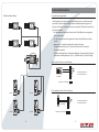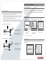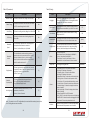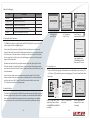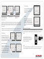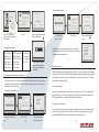
1
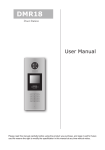
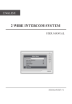
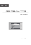
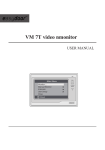
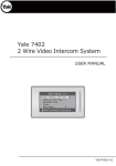
USER MANUAL (English)
VIDEO DOOR PHONE SYSTEM
Item No. : 14215
The design and specifications can be changed without notice to users.
Copyright of this manual is reserved.
1
2
3
4
5
6
7
8
9
*
0
#
Version2.0.1.2.02.27
CONTENTS
Adjustable
Camera
Camera Lens
Night View LED
Speaker
LCD Screen
350mm
ID Card Window
Digital Keypad
1
2
3
4
5
6
7
8
9
*
0
#
3 2 1
Connectiong
Port
Microphone
128mm
63mm
With Rainy Cover
2. Terminal Descriptions
SD Card Slot
L1
L2
3 2 1
J/KMB
•
•
•
•
•
•
•
•
•
•
+12V
CN-LK
EB+
EBN.O
LK+
LK-
1. Parts and Functions - - - - - - - - - - - - - - - - - - - - - - - - - - - - - - - 1
2. Terminal Descriptions - - - - - - - - - - - - - - - - - - - - - - - - - - - - - -1
3. Door Station Mounting - - - - - - - - - - - - - - - - - - - - - - - - - - - - - 2
4. System Connection - - - - - - - - - - - - - - - - - - - - - - - - - - - - - - - - 3
5. Door Lock Connections - - - - - - - - - - - - - - - - - - - - - - - - - - - - - - 5
6. Door Station Configurations - - - - - - - - - - - - - - - - - - - - - - - - - - - 7
7. Specifications - - - - - - - - - - - - - - - - - - - - - - - - - - - - - - - - - - - - - 20
1. Parts and Functions
T/R -T/R+
Bus
3 2 1
JP-LK
+12V: 12VDC power output.
LK-(GND): Power ground.
LK+(COM): Common contact of the Relay .
NO.:Normally open contact of the Relay
(Refer to DT technical guide for Lock connection detail informations).
EB+: Exit button connection port.
EB-: Exit buton connection port.
JP-LK: For electronic lock safety type setting(refer to Door Station Lock Connections).
T/R-: USB-RS485 communication terminal negative.
T/R+: USB-RS485 communication terninal positive.
Bus(L1,L2): non-polarity bus line.
-1-
3. Door Station Mounting
1
4. System Connection
2
Basic IN-OUT Wiring:
3
Camera
angle
mm
147
ON
CALL
UNLOCK
TALK/MON
1 2 3 4 56
IN-USE
395mm
Code=32, DIP-6=on
42m
m
ON
CALL
UNLOCK
The view for
rainy cover
after mounted
Drill a hole and attach
the rainy cover to it
4
Adjust the camera
angle and attach the
metal to the panel
and wire correctly.
5
TALK/MON
IN-USE
1 2 3 4 5 6
Code=31, DIP-6=off
6
ON
CALL
UNLOCK
TALK/MON
1 2 3 4 5 6
IN-USE
Code=1, DIP-6=off
Attach screws to
fix the metal box
Attach the unit
to the rainy
cover correctlly
Attach the baffle
to protect the
unit from droping
DPS
PS5
85~260AC
7
2
3
5
6
7
8
9
*
1
0
#
4
ID Code=0 (Please refer to section
6-> part 3(About Debug Tools) ->
Basic Tools Detail(table 2 -> ID
Code) in details)
The last view for all mounting
-2-
-3-
5. Door Lock Connections
Multi Door Stations Wiring:
ON
1. Internal Power Supply Mode
CALL
UNLOCK
ON
TALK/MON
IN-USE
IN-USE
1 2 3 4 5 6
Use the power of the system to supply for the electronic lock, so that the lock can be
connected to the door station directly, without an additional power supply for the
electronic lock. Note that the door station can only output 12Vdc power, therefore the
kind of lock is limited.
• The rated power of the lock must be less than 12Vdc 300mA when using internal
power supply mode.
• The GND must connect to the negative of the lock, and the COM connect to the
positive .
• Jumper set to 1-2 position for Power-off-to-Unlock safety type
(Normally closed mode); set to 2-3 position for Power-on-to -Unlock type
(Normally open mode ).
• If different unlocking time is needed to be configured, change the Unlock Timing on
door station.(In debug state,press [1 #] --> [1] Installer Setup--> [2]Unlock Timing)
CALL
UNLOCK
TALK/MON
1 2 3 4 5 6
Code=4, DIP-6=on
Code=3, DIP-6=on
ON
CALL
UNLOCK
1 2 3 4 5 6
ON
CALL
UNLOCK
TALK/MON
TALK/MON
IN-USE
IN-USE
1 2 3 4 5 6
Code=2, DIP-6=on
Code=1, DIP-6=on
DPS
PS5
A. Connection for Power-on-to-Unlock type:
85~260VAC
+12V
LK - (GND)
LK+(COM)
N.O.
EB+
EB -
+
3
2
1
12V 300mA
Set to Normally open on
the Unlock Relay mode
Jumper set to 2-3 position
JP_LK
1
2
3
5
6
7
8
9
*
0
#
4
ID Code=0
1
2
3
5
6
7
8
9
*
0
#
4
ID Code=2
B. Connection for Power--off-to-Unlock type:
+12V
LK - (GND)
LK+(COM)
N.O.
EB+
EB -
+
4
2
3
5
6
7
8
9
*
0
#
1
ID Code=3
4
2
3
5
6
7
8
9
*
0
#
3
2
1
1
ID Code=1
12V 300mA
Set to Normally Closed on
the Unlock Relay mode
Jumper set to 1-2 position
JP_LK
-4-
-5-
6. Door Station Configurations
1. About room code(address):
2. External Power Supply Mode
When the electronic lock is over 12 Vdc, additional power supply for the lock is needed.
• The power supply for the lock must be less than 48Vdc 1.5A.
• The Jumper must be removed when using external power supply. The default setting
is Power-on-to-Unlock type(Normally open mode), if use Power-off-to-Unlock type,
change the Unlock Relay mode to Normally closed mode .
• If different unlocking time is needed to be configured, change the Unlock Timing on
door station. (In debug state, press [1 #] --> [1] Installer Setup--> [2]Unlock Timing)
Room Code(also called room address) is a code assigned to each monitor, to identify
different monitors; each monitor have a unique room code in one buidling.The room
Code is stored in each Monitor’s inner EEPROM memory, and does not lose even the
monitor is power off.
2. About Debug State:
The Debug State is your starting point for using all the applications on DMR18.
>> Debug State <<
C. Connection for Power-to-Unlock type:
2
3
5
6
7
8
9
*
1
0
#
4
+
+12V
LK - (GND)
LK+(COM)
N.O.
EB+
EB -
+
3
2
1
-
Note: Cut off this line when
using external power supply
JP_LK
+
-
Remove the Jumper
2-#
Exits
When Door Station is in
standby, press '#' key
input '9008', then input the
Admin Code.(66666666 by
default)
Debug State menu is launched
Press "2#" key to exit out the debug state.
3. About Debug Tools:
set to Normally Closed on the
Unlock Relay mode
+12V
LK - (GND)
LK+(COM)
N.O.
EB+
EB -
Note: Cut off this line when
using external power supply
3
2
1
-
Tools
set to Normally Open on the
Unlock Relay mode (default)
D. Connection for Power--off-to-Unlock type:
+
Redial
1-#
Please Input Password
-
Remove the Jumper
[9008]
0-#
JP_LK
-6-
During working at Debug State,press "1#" to enter tools page,Debug Tools overviews is
shown as below:
>> Debug State <<
0-#
Redial
1-#
Tools
2-#
Exits
1. Installer Setup
2. Setup
Pres NO. 3. Card Memory
to select 4. Online Monitors
5. Online Devices
6. Voltage Measure
*Back
Tools
-7-
Basic Tools Detail :
Table 2 (Installer Setup) :
Item
Table 1 :
Item
1. Installer Setup
2. Setup
[0]
[05]
[0]
[0]
1. Language
2. Tone Select
3. Tone Volume
4. Unlock Code
5. Display Mode
6. Clock ...
7. Setup Code ...
8. About ...
9. Default ...
[1]
[03]
[08]
[1111]
1. Add Card ...
2. Delete By Card
3. Delete By M.code
4. Cards Information
5. Format
3. Card Manage
4. Online Monitors
To search the online monitors, input
the monitor code number to search
5. Online Devices
To search the online door stations.
Max.4 door station can be searched
To check the voltage of the monitor,
note that the monitor must be online.
6. Voltage Measure
-8-
Factory Set
If only one door station is installed in this building,
set to 0 ;
If multi door stations are installed, primary door
station must be set to 0, and other slave door
stations must be set from 1 to 3. Note that max.
4 door stations are available in one building
[0] Single
Unlock Timing
To set the time that how long the door keeps open
when door is released. Range from 01 to 99 seconds.
[05]
5 Seconds
Unlock Output
To set the unlock mode to match the corresponding
lock.Range from 0 to 1.
0: Power-on-to-Unlock Mode(Normally Open Mode)
1: Power-off-to-Unlock Mode(Normally Closed Mode)
0
Card Manage
To set the card location.If set to 0,the card is saved
in door station.If set to 1, the card is saved in DT-IPC
0
Doorplate Mode
To set the calling mode. If set to 0,it's the auto mode,
that means the calling will be activated directly after
inputting 2 digits code.If set to 1, it's the manual
mode,that means you should press "#" button to
activate the calling after inputting the code.
[0]
Auto mode
Audio Options ...
To set talking mode, when cutting voice or mixed
voice appears, set to 1.
DS-IM talking:set the vioce matching between
DoorStation and Indoor Monitor
DS-NT talking:set the vioce matching between Door
Station and Guard Unit
0
Submenu
1. ID Code
2. Unlock Timing
3. Unlock Output
4. Card Memory
5. Doorplate Mode
6. Audio Options ...
7. Parameters ...
8. Installer Code ...
9. Default ...
Description
ID Code
Parameters ...
Installer Code ...
Default ...
To show the parameters,please refer to table 2.1
To change door station administrator code
Note this operation is irreversible. Once restore is
activated, all parameters will return to factory default
setting except the information of access card.
-9-
[66666666]
Table 3 (Setup) :
Table 2.1(Parameters):
Item
Monitor Timing
Description
Factory Set
To show the monitor time, Range from 6s to 600s
30s
To show the surveillance time for each Door Station
or CCTV camera.Range from 6s to 600s
40s
Wait Timing
To show the calling wait time, Range from 10s to 600s
30s
Talk Timing
To show the limitation time of talking, Range from
10s to 600s
90s
Monitor &
Speak
To enable Indoor Monitor under monitoring state
can speak to Door Station at same time.
If set to 1, talk enabled; set to 0, disabled.
Monitor &
Unlock
To enable Monitors under monitoring state can
open the door at the same time.If set to 0, unlock
function is disabled; Set to 1, unlock is enable;
Set to 2,unlock is enable and close at once; Set to 3,
unlock is enable and close in 5s.
Ring Numbers
To show ring times when door station calls monitor.
4 options for choice. If set to 0, ring once. If set to 1,
ring twice. If set to 2, ring three times.
If set to 3,cycle ring.
[1]
NameList
Display Mode
To show the namelist display mode.If set to 0,
it's the DT-Config display mode.If set to 1,
it's the Simulate display mode
[0]
Working Mode
To show the working mode. If set to 0, it's the
apartment system mode.
If set to 1,it's the villa mode.
[0]
Switch Timing
[1]
Note : This section is set on DT-Config software,for more detail informations, please refer to
the DT-Config software user instructions.
-10-
Item
Description
Factory Set
Language
To change language.the code format is 4 digits.
Please refer to part 5,section 10 (change door station
language) for more detail informations.
01
Tone Select
Select the chime of Door Station in calling wait state,
12 chord tunes are available, key in 01 to 12 to select.
03
Tone Volume
Adjust the tone volume for dooor station in calling.
Range from 01~15
08
Unlock Code
To change unlock code in Common Code Unlock mode,
in 4-digits format. 1111 is the default unlock code.
Display Mode
To select the Door Station screen menu .If set to 0,
the screen displays the visitor's image when talking.
If set to 1,the screen displays icons when talking.
Clock ...
To set date and time.
Date format:if set to 0,date format is DD/MM/YY,
if set to 1,date format is MM/DD/YY.
Time format: if set to 0, time format is 24 hour
standard.If set to 1,time format is12 hour standard.
Setup Code
To change the Program Code.
About ...
1. Hardware version--To show the Door Station
(including ACS) hardware information
2. Software version--To show the Door Station
(including ACS) software information
3. Manufacture Date--To show the manufacturing date
4. Dialing Counts--To show the call operation counts
5. Calls Counts--To show the established calling counts
6. Unlock Counts--To show the unlock operation counts
7. Standby Voltage--To show the voltage that the door
station in standby.
8. Working Voltage--To show the voltage that the door
station in working.
9. Video Standard--PAL or NTSC standard
10. UI_CODE--To show the UI byte counts and check box
11. MCM-VER--To show the version and language for MCM
12. Updated--To show the updated time for UI
Default ...
Restore all Setup parameters to factory default setting,
Please note that this operation is an irreversible
-11-
[1111]
[0]
[88888888]
Table 4 (Card Manage):
Item
Description
Factory Set
1. ID Code.[1]
>> Debug State <<
2. Unlock Timing[05]
Add Card ...
To add the user card
0-#
Delete By Card
To delete card by user card
1-#
Redial
Tools
1. Installer Setup
2. Setup
Delete By M.code
To delete card by room code
Cards Information
To show the informations about cards
Format
To format informations about cards
4. Calling and Unlock Operation:
2-#
To o l s
Exits
3. Card Memory
Pres NO. 4 . O n l i n e M o n i t o r s
to select 5 . O n l i n e D e v i c e s
*Back
In Debug State,
press '1#' key
6 . Vo l t a g e M e a s u r e
In Tools menu,
press '1' key
The Default Set is very important. When the door station miss up the settings in anyway,
the most quickly and easy way to solve the problem is to activate the default setting on
door station. The default settings already have all the right settings for one-building
system, that means the system will work normally without any additional settings.
-12-
8. Installer Code...
9. Default
*Back
Press '9' key, a
password will be asked
Please Input Password
*Back
# Save
Input Installer code
(66666666 by default),
then press"#" to save
6. Change Ring Tone:
There are 12 different ringtones, If door station runs as Debug State, you can press [1 #]
-->[2] Setup--> [2]Tone Select to enter tone setting page .If it runs as Normal State, follow
these steps:
[ 8002 ]
Setup
1
2
3
4
5
6
7
8
9
*
0
#
Please Input Password
Press “#”,Input “8002”, then
input Setup Code or Admin
Code(88888888 or 66666666
by default)
1. Language
[1]
2 . To n e S e l e c t [ 0 3 ]
3 . To n e V o l u m e [ 0 3 ]
2 . To n e S e l e c t [ 0 3 ]
[--]
4. Unlock Code[1111]
5. Display Mode
RF CARD
5. About Default Set:
6. Audio Options ...
7. Parameters ...
[--------]
Visitors can call the apartment by dialing the Flat Code (apartment number) on the
keypad. If they don’t know the Flat Code (apartment number), they can search the name
list on the screen. If the door station is in standby, visitors need to press '9#' to display
the user name list. Press"#" key to scroll next/last page. and use key 1 to 8 key on each
page to call the desired flat.
Note: If the door station works as apartment system mode,input 01~32 to call the
relevant monitor.If the door station works as villa mode,input 01 to call the monitors
which its code is from 00~15. Input 02 to call the monitors which its code is from
16~31.please refer to table 2.1(working mode)
5. Doorplate Mode
Press No.
to select
9. Default...
The DMR18 door station is a digital station with 320*240 pixels LCD screen, color CCD
camera, night view LED, and digital keypad.
Residents can open the door by using their unique Unlock Code (four-digit PIN code).
If the door station is in standby mode, press '#' key, then input the four-digit unlock to
open the door.Please refer to part 5,section 7(How to use code unlock function) for more
detail information.
3. Unlock Output[0]
Installer
4. Card Memory [0]
Setup
Press No.
to select
*Back
6. Clock
7. Setup Code
8. About
9. Default
( 01~12)
*Back
Press “2” to enter tone
select item.
-13-
# Save
Input 2 digits number,
then press “#” to save
the setting
9. Change Unlcok Code:
7. Change Installer Code(administrator password):
The Installer Code is the password to access the door station debug State. The default
Installer Code is '66666666'. Note that if the Default Set have been activated, the Installer
Code will be set to default value.
1. ID Code
>> Debug State <<
If door station runs as Debug State, you can press “1#” to activate Tools Menu, then
select “2” to enter setup page,then select 4 item.If it runs as Normal State, follow these
steps:
[1]
2. Unlock Timing[05]
0-#
Redial
1-#
To o l s
2-#
Exits
1. Installer Setup
Tools
2. Setup
3. Card Memory
Pres NO. 4 . O n l i n e M o n i t o r s
to select 5 . O n l i n e D e v i c e s
6 . Vo l t a g e M e a s u r e
*Back
In Debug State,
press '1 #' key
3. Unlock Output[0]
Installer
4. Card Memory [0]
Setup
8. Installer Code...
9. Default
*Back
press '1'
press '8'
8. Installer Code...
[--------]
*Back
1
2
3
4
5
6
7
8
9
*
0
#
Please Input Password
Press “#”,Input “8002”,
then input Setup Code or
Admin Code(88888888 or
66666666 by default)
4. Unlock Code[1111]
[----]
4. Unlock Code[1111]
5. Display Mode
Press No.
to select
*Back
6. Clock
7. Setup Code
8. About
9. Default
Press “4” to enter
unlock code item.
( * * * *)
*Back
# Save
Input 4 digits number,
then press “#” to
update
10. User Card Management:
( * * * * * * * *)
# Save
Input a new Installer Code
and then press '#' key to
confirm
8. How to use code unlock function:
[ 8002 ]
5. Doorplate Mode
Press1~9 6 . A u d i o O p t i o n s . . .
to select 7 . P a r a m e t e r s . . .
Setup
1. Language
[1]
2 . To n e S e l e c t [ 0 3 ]
3 . To n e V o l u m e [ 0 3 ]
This section explains how to configure the key fob function on DMR18,The key fob is used
to open the lock. Total 1000 key fobs can be registered with one door station. When
swiping the fob to the door station, the distance must be less than 3 centimeter.
Key Fobs must be registered on the Door station that can be used to open the door.
Register the Key Fobs:
Please refer to the following operations:
i
[8017 ]
All the registered key fobs are called User Cards/User Key Fobs. New fobs/cards need to
be registered one by one to the Door station to become a valid User Card/User Key Fob;
and every User Card/User Key Fob is related to a certain Monitor Address (Flat code).
RF CARD
1
2
4
5
6
7
8
3
9
*
0
#
[9008]
1
2
3
4
5
6
7
8
9
*
0
#
Please Input Password
When the Door Station is
in standby, Press “#”
Input 4 digits Unlock
Code directly
-14-
When the Doors tation is standby, press [#] --> [9008] -->Password([66666666 by
default]) to get into the Debug Mode Menu, then Press [1 #] --> [3] Card Manage -->[1]
Add Card to get into the Add Card page. Please see the followings.
If verified correctly,
door open
-15-
[--]
[01]
* Back
# Save
Enter Add Card menu,
and Room Code is asked.
4. Cards Information
Enter Card Information page, and the
screen will display the authorized User
Cards count, and card read access
events count.
[01]
C a r d numbs : 1 5 9 7 7 1 3 1
Show the card
Show The Card
* Back
# Save
* Back
# Save
Us
C a er
rd
Please Input Room Code
Card information:
1. AddCard ...
Input Room Code
Registered User Cards/Key Fobs can be deleted from the Door station,once doing the delete
operation,the card/key fobs can not open the door anymore. They can also be re-registered
again to become a valid User Card/User Key Fob. There are two ways to delete User Cards/
User Key Fobs:
1. Delete by card: show the unwanted card(s) when the Door station is in Delete Card Mode
2. Delete by room number: delete all the registered User Cards related to that room No.
2. Delete By Card ...
# Save
5. Format
Enter Card Format page, a password
will be asked,input 8 digits installer
password (66666666 by default),then
press" #" key to save,format operation
is activated.all card information will be
cleared.
[--------]
Please Input Password
* Back
# Save
11. Change Door Station Language:
It's convenient to change the user interface for DMR18.Just put the config files to the SD
card and by means of the digital keypad of door station,only 30 seconds is needed to
update.
Show The Card
Show The Card
* Back
# Save
* Back
# Save
Insert SD card
SD Card Slot
C a r d numbs:1 5 9 7 7 1 3 1
Us
C a er
rd
In Debug State , Press [1 #] --> [3]
Card Manage -->[2] Delete By Card
to enter Delete by Card page.as
shown on the right, then show the
cards you want to delete one by one.
2. Delete By Card ...
* Back
Format:
Read the card to be
authorized
Delete user cards:
Delete By Card:
Card Count: 1000
Step 1: Insert the SD card which is
contained config files into the SD card slot
where is at the back of the door station.
Refer to the right diagram.
L1 L2
CN-LK
J/KMB
+12V
1. AddCard ...
EB+
EBN.O
LK+
LK-
1. AddCard ...
T/R -T/R+
Bus
3 2 1
JP-LK
3 2 1
Delete by Room Number:
3. Delete By M.code
In Debug State , Press [1 #] --> [3]
Card Manage -->[3] Delete By M.Code
to enter Delete by M.Code page.as
shown on the right, then Input the
Room Code, press “#” to confirm; all
associated cards will be deleted.
3. Delete By M.code
[01]
[--]
Please Input Room Code
* Back
-16-
# Save
Updat ed
* Back
Step 2:
If door station runs as Debug State, you can press “1#” to activate Tools Menu, select “2”
to enter setup page,then select 1 item.If it runs as Normal State, follow these steps:
# Save
-17-
Setup
[ 8002 ]
1
2
3
4
5
6
7
8
9
*
0
#
1. Language
[1]
2 . To n e S e l e c t [ 0 3 ]
3 . To n e V o l u m e [ 0 3 ]
Check online monitors:
1. Language
5. Display Mode
Press No.
to select
Please Input Password
6. Clock
7. Setup Code
8. About
9. Default
*Back
>> Debug State <<
[----]
4. Unlock Code[1111]
( Code Number)
*Back
# Save
0-#
Redial
1-#
To o l s
2-#
Exits
4. Online Monitors
Tools
Press 1
Input 4 digits code number,
Refer to the table.
In Debug State,
press '1 #' key
[--]~[--]
2. Setup
3. Card Memory
Pres NO. 4 . O n l i n e M o n i t o r s
to select 5 . O n l i n e D e v i c e s
*Back
Press “#”,Input “8002”,
then input Setup Code or
Admin Code
1. Installer Setup
6 . Vo l t a g e M e a s u r e
Press '4' key
(Search Range)
* Back
# Save
Input 2 digits monitor
code
4#.Online Monitors
Language code number:
8101: English
8102: French
8103: Spanish
8104: Italian
8105: German
8106: Dutch
i
8107: Portuguese
8108: S-Chinese
8109: T-Chinese
8110: Greek
8111: Turkish
8112: Polish
8113: Russian
8114: Slovakia
8115: Hungray
8116: Czech
[8017 ]
When the door station
output a long sound DI...,
that means UI updating
is finished.
“Online Search” is a very useful function that can help the installer to easily check the
connectivity of all the Monitors. Please note, Online does not mean via the internet.
Please refer to the followings:
Check online door stations:
Tools
0-#
Redial
1-#
To o l s
2-#
Exits
1. Installer Setup
5. Online Devices
[DS1 ] : Online
[DS2 ] : Fail
[DS3 ] : Fail
[DS4 ] : Fail
2. Setup
3. Card Memory
4. Online Monitors
In Debug State, press '1 #'
key
Pres NO. 5 . O n l i n e D e v i c e s
to select
6 . Vo l t a g e M e a s u r e
* Back
*Back
Press '5' key
-18-
[ 01 ]
[ 02 ]
[ 03 ]
[ 04 ]
[ 05 ]
* Back
12. Search online door stations and monitors:
>> Debug State <<
Search Range: input the monitor adress. For example,
input the range from 01 to 05. You will see the connection
status of the selected moinitors.
Online
Online
Online
Fall
Online
# Save
13. Namelist function:
DMR18 is designed to have digital keypad and big TFT screen. Its namelist was shown on
the screen and customer can do the calling operation through the digital keypad guided
by Namelist on the screen. 2 types of namelist can be shown on the screen : DT-Config
namelist and Simulate namelist.
Enter namelist page:
Press '9#' in standby mode to display the user namelist. Press"#" key to scroll next/last
page. and use key 1 to 8 key on each page to call the flat you want.Please refer to the
DT-Config softwre user instructions for configure the namelist.
Send namelist to monitors
# Save
Check door stations
connection status
The namelist can be sent to monitors by door station directly.Connect the door station
and montiors correctly to the system.Then press # 8012 in standby mode ,and input
password (66666666 by default) to send namelist to all the monitors.
-19-
7. Specification
•
•
•
•
•
•
•
Power supply : DC24V(Powered by DT-DPS)
Camera Lens : 1/4 ACS 4T image sensor with DSP processor
Power consumption : Standby 3W;Working status 9W
Screen : 3.5 inch TFT
Resolution : 320(R, G, B)X240 pixels
Video signal : CCIR/EIA Optional
Wiring : 2 wires, non-polarit
-20-