1
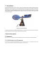
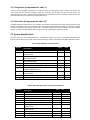
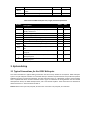
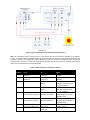
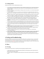
ELEC483 Lab Manual 2DOF Helicopter Setups Dan Li, 2013 2DOF HELICOPTER SETUPS ........................................................................................................................................ 1 DAN LI, 2013 .................................................................................................................................................................. 1 1. PRESENTATION .............................................................................................................................................. 2 2. SYSTEM DESCRIPTION ........................................................................................................................................... 2 2.1 COMPONENTS ............................................................................................................................................................ 2 2.2 SYSTEM SPECIfiCATIONS ................................................................................................................................................ 4 3. SYSTEM SETUP ...................................................................................................................................................... 5 3.1 TYPICAL CONNECTIONS FOR THE 2DOF HELICOPTER .......................................................................................................... 5 4. TESTING AND TROUBLESHOOTING ........................................................................................................................ 7 4.1 MOTOR ..................................................................................................................................................................... 7 4.2 ENCODER ............................................................................................................................................................... 8 5. EXPERIMENT SAMPLE FILES .................................................................................................................................. 8 5.1 OVERVIEW ................................................................................................................................................................. 8 5.2 OPEN-LOOP IMPLEMENTATION ...................................................................................................................................... 9 REFERENCES............................................................................................................................................................ 12 1. Presentation The Quanser 2DOF Helicopter, shown in Figure 2, consists of a helicopter model mounted on a fixed base with two propellers that are driven by DC motors. The front propeller controls the elevation of the helicopter nose about the pitch axis and the back propeller controls the side to side motions of the helicopter about the yaw axis. The pitch and yaw angles are measured using high-resolution encoders. The pitch encoder and motor signals are transmitted via a slip ring. This eliminates the possibility of wires tangling on the yaw axis and allows the yaw angle to rotate freely about 360 degrees. Figure 1: Quanser 2DOF Helicopter In Section 2 the components composing the 2DOF Helicopter are described and the system specifications are given. Section 3 explains how to setup the system and gives the wiring procedure. 2. System Description 2.1 Components Section 2.1.1 lists the components on the 2DOF Helicopter plant and 2.2 summarizes the system specfications. 2.1.1 2DOF Helicopter Overall Components The components comprising the 2DOF Helicopter system are labeled in Figure 2, are described in Table 1. The motors, propeller assemblies, and encoders are described in more detail below. Figure 2: Components Table 1: 2DOF Components ID # 12 34 56 78 9 10 11 12 Component Back propeller Back propeller shield Yaw/back motor Pitch encoder Yoke Helicopter body Front propeller Pitch/front motor Front propeller shield Encoder/motor circuit Encoder connector on circuit (not used) Motor connector on circuit ID # 13 14 15 16 17 18 19 20 21 22 23 Component Metal shaft rotates about yaw axis Slip ring Yaw encoder Base platform Front motor connector Right motor connector (not used) Back motor connector Yaw encoder connector Roll encoder connector (not used) Pitch encoder connector Left motor connector (not used) 2.1.2 DC Motors (Components #3 and #8) The 2DOF Helicopter has two DC motors: the yaw motor, component #3, actuating the back propeller and the pitch motor, component #8, rotating the front propeller. The yaw motor is a Faulhaber Series 2842 Model 006C motor. It has a terminal resistance of 1.6 Ω and a currenttorque constant of 0.0109 N.m/A. See [1] for the full specifications of this motor. The larger pitch motor is a Pittman Model 9234. It has an electrical resistance of 0.83 Ω and a current-torque constant of 0.0182 N.m/A. The rated voltage of the motor is 12 V but its peak voltage can be brought up to 22 V without damage. See [3] for the full specifications of this motor. 2.1.3 Propellers (Components #1 and #7) The pitch and yaw propeller assemblies are composed of the actual propeller, which is directly mounted to the motor shaft, and the aluminum propeller shield. The propellers used for both the pitch and yaw motors are Graupner 20/15 cm or 8/6”. The pitch motor/propeller has an identified thrust-force constant of 0.104 N/V and the yaw motor/propeller has a thrust-force constant of 0.43 N/V. 2.1.4 Encoders (Components #4 and #15) The 2DOF Helicopter experiment has two encoders: the encoder measuring the pitch angle, component #4, and the encoder measuring the yaw angle, component #15. In quadrature mode, the pitch encoder has a resolution of 4096 counts per revolution and the yaw encoder has a resolution of 8192 counter per revolution. Thus the effective position resolution is 0.0879 degrees about the pitch axis and 0.0439 degrees about the yaw axis 2.2 System Specifications The main parameters of the 2DOF Helicopter is summarized in Table 2. The motor and encoder specifications are listed in Table 3 below. Finally, Table 4 lists various dimensions, masses, and inertias of the 2DOF Helicopter system. Table 2: 2DOF Helicopter model parameters Symbol Kpp Kyy Kpy Kyp Beq, Beq, mheli lcm Jeq, Jeq, Description Thrust force constant of yaw motor/propeller Thrust torque constant of yaw axis from yaw motor/propeller Thrust torque constant acting on pitch axis from yaw motor/propeller Thrust torque constant acting on yaw axis from pitch motor/propeller Equivalent viscous damping about pitch axis Equivalent viscous damping about yaw axis Total moving mass of the helicopter (body, two propeller assemblies, etc.) Center of mass length along helicopter body from pitch axis Total moment of inertia about pitch axis Total moment of inertia about yaw axis. Value Unit 0.204 0.072 N.m/ N.m/ 0.0068 N.m/ 0.0219 N.m/ 0.800 0.318 1.3872 N/ N/ kg 0.186 0.0384 0.0432 kg.m2 kg.m2 Table 3: 2DOF Helicopter motor and encoder specifications Symbol Rm, Rm, Kt, Kt, Jm, Jm, Kf, Kf, mm, mm, KEC,LN, Description Armature resistance of pitch motor Armature resistance of yaw motor Current-torque constant of pitch motor Current-torque constant of yaw motor Rotor moment of inertia of pitch motor Rotor moment of inertia of yaw motor Pitch propeller force-thrust constant (found experimentally) Yaw propeller force-thrust constant (found experimentally) Mass of pitch motor Mass of yaw motor Yaw encoder resolution (in quadrature Value 0.83 1.60 0.0182 0.0109 1.91 10− 1.37 10− 0.1037 Unit N.m/ N.m/ kg.m2 kg.m2 N/ 0.428 N/ 0.292 0.128 8192 kg kg counts/rev KEC,LN, KEC, KEC, mode) Pitch encoder resolution (in quadrature mode) Yaw encoder calibration gain pitch encoder calibration gain 4096 counts/rev 7.67 10− 1.50 10− rad/counts rad/counts Table 4: Various 2DOF Helicopter mass, length, and inertia parameters Symbol mshield mprops mbody, mbody, mshaft Lbody Lshaft Jbody, Jbody, Jshaft Jp Jy Description Mass of propeller shield Mass of pitch and yaw propellers, propeller shields, and motors Mass moving about pitch axis Mass moving about yaw axis Mass of metal shaft rotating about yaw axis Total length of helicopter body Length of metal shaft rotating about yaw axis Moment of inertia of helicopter body about pitch axis Moment of inertia of helicopter body about yaw axis Moment of inertia of metal shaft about yaw axis end point Moment of inertia of front motor/shield assembly about pitch pivot Moment of inertia of back motor/shield assembly about yaw pivot Value Unit 0.167 0.754 kg kg 0.633 0.667 0.151 0.483 0.280 0.0123 kg kg kg 0.0129 kg.m2 0.0039 kg.m2 0.0178 kg.m2 0.0084 kg.m2 kg.m2 3. System Setup 3.1 Typical Connections for the 2DOF Helicopter This section describes the typical cabling connections that are used by default for the Quanser 2DOF Helicopter system. The yaw and pitch encoders are connected directly to the data-acquisition board. This provides the position feedback necessary to control the helicopter. The data-acquisition board, i.e., DAQ board, outputs a control voltage that is amplified and drives the front and back motors. Figure 3.7 illustrates the wiring between the two-channel data-aquisition device, the 2DOF Helicopter base, and a two-channel amplifier. These connections are described in detail in Section 3.1.1 and summarized in Table 5. Caution: Pitch motor input: 24V, 5A peak, 3A continuous. Yaw motor: 15V, 3A peak, 1A continuous. Figure 3: Typical connections of the 2DOF Helicopter Experiment Note: The connections shown in Figure 3.7 uses a two-channel DAQ and a two-channel amplifier as an example. Further, it is assumed that the amplifier needs to be enabled through the digital output and that an Emergency Stop has to be connected. Your configuration may be different. For instance, you may have a DAQ with more IOs than the one presented in Figure 3.7 or have two single-channel amplifiers that do not require any enabling and E-Stop (in which case, you would omit connections #7 and #8). Table 5: 2DOF Helicopter system wiring summary Cable # 1 3 From Terminal Board: Analog Output #0 Terminal Board: Analog Output #1 Amplifier 0: To Load To Amplifier 0: Command Amplifier 1: Command 2DOF Helicopter: M0 (Pitch) 4 Amplifier 1: To Load 2DOF Helicopter: M1 (Yaw) 5 2DOF Helicopter: Pitch Encoder ENC 0 connector Terminal Board: Encoder Channel #0 6 2DOF Helicopter: Yaw Encoder ENC 1 connector Terminal Board: Encoder Channel #1 7 Amplifier 16-pin connector (Enable/Fault) Emergency Stop Switch Terminal Board: DIO 0 connector Amplifier E-Stop connector 2 8 Signal Control signal to the pitch amplifier. Control signal to the yaw amplifier. Power leads to the 2DOF Helicopter’s front DC motor (i.e., pitch propeller) Power leads to the 2DOF Helicopter’s back DC motor (i.e., yaw propeller) 2DOF Helicopter’s pitch angle feedback signal to the data acquisition card 2DOF Helicopter’s yaw angle feedback signal to the data acquisition card Enable signal for the amplifier channels Emergency stop signal 3.1.1 Wiring Details Follow these steps to connect the 2DOF Helicopter system: 1. It is assumed that the Quanser DAQ board is already installed as discussed in [2]. If another data-acquisition device is being used, e.g. NI M-Series board, then go to its corresponding documentation and ensure it is properly installed. 2. Make sure everything is powered off before making any of these connections. This includes turning off your PC and the amplifier. 3. Connect one of the connectors on the 2x RCA to 2x RCA cable from the Analog Output Channel #0 on the terminal board to the Amplifier Command Connector on the Quanser amplifier. See cable #1 shown in Figure 3.7. 4. Connect the other line of the 2XRCA to 2XRCA cable from the Analog Output #1 connector on the terminal board to the Amplifier 1 Amplifier Command connector. This is illustrated by connection #2 in Figure 3.7. 5. Connect a 4-pin-DIN to 6-pin-DIN cable from Amplifier 0 To Load (3x Amplifier Command) connector, to the M0 (Pitch) connector on the 2DOF Helicopter plant. This is illustrated by connection #3 in Figure 3.7. 6. Connect another 4-pin-DIN to 6-pin-DIN cable from the Amplifier 1 To Load (3x Amplifier Command) connector, to the M1 (Yaw) connector on the 2DOF Helicopter plant. This is illustrated by connection #4 in Figure 3.7. 7. Connect a 5-pin-stereo-DIN to 5-pin-stereo-DIN cable from the Encoder 0 connector on the terminal board, to the Enc 0 (Pitch) connector on the 2DOF Helicopter plant. This is illustrated by connection #5 in Figure 3.7. 8. Connect another 5-pin-stereo-DIN to 5-pin-stereo-DIN cable from the Encoder 1 connector on the terminal board to the Enc1 (Yaw) connector on the 2DOF Helicopter plant. This is illustrated by connection #6 in Figure 3.7. 9. Caution: CAUTION: Any encoder should be directly connected to the Quanser terminal board (or equivalent) using a standard 5-pin DIN cable. DO NOT connect the encoder cable to the amplifiers! 10. Connect the 16-pin ribbon cable from the DIO 0 connector on the terminal board to the 16pin connector (Enable/Fault) on the amplifier. This is illustrated by connection #7 in Figure 11. Connect the emergency stop switch to the E-Stop connector on the amplifier. This is illustrated by connection #8 in Figure 3.7. 12. If you are using are using the Logitech Attack 3 USB joystick shown in Figure 3.8, then connect the USB cable from the joystick to a USB port on the PC while it is running. The system should detect the joystick and automatically install the driver (you will be prompted). See the Logitech Installation Manual for more information on the setup procedure. See 3.2 for more information on system requirements of the Logitech joystick and how to use the Rate Command knob. 4. Testing and Troubleshooting This section describes some functional tests to determine if 2DOF system is operating normally. It is assumed that the 2DOF Helicopter is connected as described in Section 3.1. To carry out these tests, it is preferable if the user can use software such as QUARC to read sensor measurements and feed voltages to the motor. Alternatively, these tests can be performed with signal generator and an oscilloscope. 4.1 Motor 4.1.1 Testing Ensure the pitch and yaw motors are operating correctly by going through this procedure: Apply approximately 4V to Analog Output Channel #0 of the terminal board to test the pitch motor and verify that the front propeller rotates. Similarly, apply 4V to Analog Output Channel #1 to drive the yaw motor and verify that the rear propeller rotates. 4.1.2 Troubleshooting If the motor is not responding to voltage signal, go through these steps: Verify that the power amplifier is functional. For example when using the Quanser VoltPAQ device, is the green LED lit? Check that the data-acquisition board is functional, e.g. ensure it is properly connected, that the fuse is not burnt. Make sure the voltage is actually reaching the motor terminals (use voltmeter or oscilloscope). If the motor terminals are receiving the signal and the motor is still not turning, your motor might be damaged and will need to be repaired. Please see 5 for information on contacting Quanser for technical support. 4.2 Encoder 4.2.1 Testing Follow this procedure to test each encoder on their respective motors: 1. Measure Encoder Input Channel #0 and rotate the pitch angle by moving the helicopter nose (i.e., front propeller) up and down. This encoder measures 4096 counts for every revolution. Moving it from the downward, resting position to the horizontal is about 40 degrees. Thus it should read approximately 455 counts. 2. Similarly, measure the Encoder Input Channel #1. This encoder measures 8192 counts per full revolution. Rotate the helicopter body one full rotation and verify that 8192 is being measured. Note: Some data acquisition systems do not measure in quadrature and, in this case, one-quarter of the expected counts are received, i.e. 1024 counts in the pitch. In addition, some data acquisition systems measure in quadrature but increment the count by 0.25 (as opposed to having an integer number of counts). Make sure the details of the data-acquisition system being used are known. The counters on the Quanser DAQ boards measure in quadrature and therefore a total of four times the number of encoder lines per rotation, e.g. 1024-line encoder results in 4096 integer counts for every full rotation. 4.2.2 Troubleshooting If the encoder is not measuring properly, go through this procedure: Check that the data-acquisition board is functional, e.g. ensure it is properly connected, that the fuse is not burnt. Check that both the A and B channels from the encoder are properly generated and fed to the dataacquisition device. Using an oscilloscope, there should be two square waves, signals and B, with phase shift of 90 degrees. If this is not observed then the encoder may be damaged and need to be replaced. Please see section 5 for information on contacting Quanser for technical support. 5. Experiment Sample Files 5.1 Overview Table 6 below lists and describes the various sample files supplied with the 2DOF Helicopter experiment. File Name Description Table 6: Sample Files supplied with the 2DOF Helicopter experiment File Description 2DOF Heli Equations.mws 2DOF Heli Equations.html quanser.ind and quanser.lib setup_lab_heli_2d.m setup_heli2d_configuration.m HELI2D_ABCD_eqns.m d_heli2d_lqr.m d_heli2d_lqr_i.m s_heli_2d_ff_lqr_i.mdl q_heli_2d_ff_lqr_i.mdl q_heli_2d_open_loop.mdl Maple worksheet used to analytically derive the state-space model involved in the experiment. Waterloo Maple 9, or a later release, is required to open, modify, and execute this file. HTML presentation of the Maple Worksheet. It allows users to view the content of the Maple file without having Maple 9 installed. No modifications to the equations can be performed when in this format. The Quanser_Tools module defines the generic procedures used in Lagrangian mechanics and resulting in the determination of a given system’s equations of motion and state-space representation. It also contains data processing routines to save the obtained state-space matrices into a Matlab-readable file. The main Matlab script that sets the model, control, and configu-ration parameters. Run this file only to setup the laboratory. Returns the 2DOF Helicopter model parameters and encoder calibration constants. Matlab script file generated using the Maple worksheet 2DOF Heli Equations.mws. It sets the A, B, C, and D matrices for the state-space representation of the 2DOF Helicopter open-loop system. Matlab script that generates the position-velocity controller gain K using LQR. Matlab function that the position-integral-velocity controller gain K using LQR. Simulink file that simulates the open-loop or closed-loop 2DOF Helicopter using a nonlinear model of the system. Simulink file that implements the real-time position controller for the 2DOF Helicopter system. Simulink file that runs the 2DOF Helicopter in open-loop, i.e. al-lows user to command voltage directly to motors. 5.2 Open-loop Implementation 1. 2. Load the Matlab software. Open Simulink model q_heli_2d_open_loop.mdl shown in following Figure 4. The model runs your actual 2DOF Helicopter plant by directly interfacing with your hardware through the QUARC blocks, described in [1]. Figure 4: Simulink diagram to run 2DOF Helicopter in open-loop with QUARC 3. 4. 5. 6. Configure setup script: Open the design file setup_lab_heli_2d.m and ensure everything is configured properly. The K_JOYSTICK_V_X and K_JOYSTICK_V_Y parameters control the rate that a voltage command is generated. The JOYSTICK_X_DZ and JOYSTICK_Y_DZ specify the deadzone of the joystick. The deadzone is used to remove negligible joystick outputs due to noise or from small motions in the joystick handle. Execute the setup_lab_heli_2d.m Matlab script to setup the workspace before compiling the diagram and running it in real-time with QUARC. Open the 2DOF HELI subsystem. Its contents are shown in Figure 5.16. This subsystem contains the QUARC blocks that interface with the hardware of the actual plant. The Analog Output block sends the voltage computed by the controller to the DAQ device which drives the actuators and the Encoder Input block reads the encoder measurements. Configure DAQ: Double-click on the HIL Initialize block in the Simulink diagram and ensure it is configured for the DAQdevice that is installed in your system. By default the block shown in Figure 5 is setup for the Quanser Q8 hardware-in-the-loop board. Figure 5: 2DOF HELI subsystem contains QUARC blocks that interface with hardware 7. 8. 9. 10. 11. 12. 13. 14. 15. 16. The voltage sent to the Analog Output block is amplified by the amplifiers and applied to the power amplifier’s attached motor. Note that the control input is divided by the amplifier gain, K_AMP, before being sent to the DAQ board. This way, the amplifier gain does not have to be included in the mathematical model as the voltage output from the controller is the voltage being applied to the motor. The amplifier and DAQ saturation blocks limit the amount of voltage that can be fed to the motor. Open the theta (deg), psi (deg), and Vm (V) scopes in the Scopes folder. These scopes display both the desired and measured angles of the Helicopter as well as the voltages being applied to the front and back motors. Ensure the helicopter has been setup and all the connections have been made as instructed in the 2DOF Helicopter User Manual. Turn ON the amplifier. For the VoltPAQ-X2, the green LED on the amplifier should be lit. 11. In the q_heli_2d_open_loop Simulink diagram, make sure the Program/Joystick block shown in Figure 5.15 is set to 2 in order to generate the desired voltage from the joystick. Click on QUARC j Build to compile the code from the Simulink diagram. Select QUARC j Start to begin running the controller. Try to bring the helicopter body to a horizontal by pulling the joystick handle toward you.This supplies a positive voltage to the pitch motor and causes the pitch angle to increase As depicted in Figure 5.17, you will notice that the yaw angle moves clockwise in the positive direction as the voltage in the pitch motor increases. Compensate for this coupling effect by moving the joystick arm to the left and apply a negative voltage to the yaw motor. As illustrated, the pitch is eventually stabilized at about 0 degrees when the pitch motor voltage is approximately 12.5 V and the yaw begins to stabilize when feeding a voltage of about -6.0 V to the yaw motor. From this point, now try decreasing the yaw voltage and observe its effect on the pitch angle. Figure 6: Effect of pitch on yaw 17. As depicted in Figure 6, applying a negative voltage to the yaw motor causes the pitch angle to decrease, i.e. the helicopter nose goes down. Similarly to the effect the pitch motor has on the yaw motion, the voltage applied to the yaw motor generates a torque on the pitch axis 18. Gradually bring the helicopter back to starting position. 19. Click on the Stop button on the Simulink diagram tool bar (or select QUARC j Stop from themenu) to stop running the controller. 20. If the laboratory session is complete, power off the amplifier. References [1] [2] [3] [4] [5] Faulhaber. Model 006C Motor Series 2842, 2003. Quanser Inc. Q2-USB Data-Acquisition System User’s Guide, 2010. Pittman. LO-COG DC Servo Motors 8000, 9000, 14000, 2010. Quanser 2DOF Helicopter Laboratory Manual, Quanser 2011 Quanser 2DOF Helicopter User Manual, Quanser, 2011