1
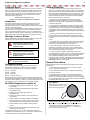
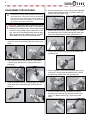
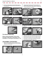
AUTHORIZED TECHNICIAN
TECHNICAL MAINTENANCE MANUAL
CALYPSO FIRST STAGE
Contents
Copyright notice................................................................................................................................................3
Introduction........................................................................................................................................................3
Warnings, Cautions, & Notes.........................................................................................................................3
Scheduled Service............................................................................................................................................3
General Guidelines...........................................................................................................................................3
General Conventions.......................................................................................................................................3
Disassembly Procedures...............................................................................................................................4
REASSEMBLY PROCEDURES................................................................................................................................5
Final TESTING........................................................................................................................................................7
Checking Medium Pressure................................................................................................................................................................. 7
Immersion Test...................................................................................................................................................................................... 7
Table 1 - First-stage troubleshooting guide........................................................................................8
Table 2 - Recommended tool list.................................................................................................................9
Table 3 - TORQUE SPECIFICATIONS................................................................................................................10
TABLE 4 -tEST BENCH specifications...........................................................................................................10
Table 5 - RECOMMENDED LUBRICANTS AND CLEANERS............................................................................. 11
procedure a - cleaning and lubrication...............................................................................................12
exploded parts dIAGRAM...............................................................................................................................14
Calypso First Stage Service Manual
Copyright Notice
General Guidelines
This manual is copyrighted, all rights reserved. It may not, in whole or in
part, be copied, photocopied, reproduced, translated or reduced to any
electronic medium or machine-readable form without prior consent in
writing from Aqua Lung America. It may not be distributed through the
internet or computer bulletin board systems without prior consent in
writing from Aqua Lung America.
1. In order to correctly perform the procedures outlined in this
manual, it is important to follow each step exactly in the order given.
Read over the entire manual to become familiar with all procedures
before attempting to disassemble the product in this manual, and to
learn which specialty tools and replacement parts will be required.
Keep the manual open beside you for reference while performing
each procedure. Do not rely on memory.
©2007 Aqua Lung America, Inc.
Calypso First Stage Technical Maintenance Manual
2. All service and repair should be carried out in a work area
specifically set up and equipped for the task. Adequate lighting,
cleanliness, and easy access to all required tools are essential for
an efficient repair facility.
Introduction
This manual provides factory prescribed procedures for the correct
service and repair of the Aqua Lung® or Apeks regulator products
described in this manual. It is not intended to be used as an instructional
manual for untrained personnel.
The procedures outlined within this manual are to be performed only by
personnel who have received Factory Authorized training through an
Aqua Lung Service & Repair Seminar. If you do not completely understand all of the procedures outlined in this manual, contact Aqua Lung® to
speak directly with a Technical Advisor before proceeding any further.
3. As the regulator is disassembled, reusable components should
be segregated and not allowed to intermix with nonreusable parts
or parts from other units. Delicate parts, including inlet fittings and
crowns which contain critical sealing surfaces, must be protected
and isolated from other parts to prevent damage during the cleaning
procedure.
4. Use only genuine Aqua Lung® parts provided in the overhaul
parts kit for this product. DO NOT attempt to substitute an Aqua
Lung® part with another manufacturer’s, regardless of any similarity
in shape
or size.
Warnings, Cautions, & Notes
Pay special attention to information provided in warnings, cautions and
notes that are accompanied by one of these symbols:
5. Do not attempt to reuse mandatory replacement parts under any
circumstances, regardless of the amount of use the product has
received since it was manufactured or last serviced.
WARNINGS indicate a procedure or
situation that may result in serious
injury or death if instructions are not
followed correctly.
6. When reassembling, it is important to follow every torque
specification prescribed in this manual, using a calibrated torque
wrench. Most parts are made of either marine brass or plastic, and
can be permanently damaged by undue stress.
CAUTIONS indicate any situation or
technique that will result in potential
damage to the product, or render the
product unsafe if instructions are not
followed correctly.
7. In order to make the regulator compatible with nitrox up to
40%O2 (EAN40), the regulator must be properly cleaned, lubricated
and assembled using genuine Aqua Lung® or Apeks replacement
parts. In addition, assembly must be carried out in a clean
environment using powderless, latex gloves or equivalent. For more
detailed information, be sure to read Procedure A: Cleaning and
Lubricating at the back of this manual.
NOTES are used to emphasize important
points,tips and reminders.
General Conventions
Scheduled Service
Unless otherwise instructed, the following terminology and techniques
are assumed:
1. When instructed to remove, unscrew, or loosen a threaded
part, turn the part counterclockwise.
If the regulator is subjected to less than 50 dives per year, it is
permissible to overhaul it every other year with an inspection
procedure being performed on the “off” years. For example:
Year #1: Inspection
Year #2: Overhaul
Year #3: Inspection
Year #4: Overhaul, and so on.
Both Inspections and Overhauls need to be documented in the Annual
Service & Inspection Record in the back of the Owner’s Manual to keep
the Limited Lifetime Warranty in effect. If a regulator is subjected to more
than 50 dives per year, it should receive the complete overhaul.
2. When instructed to install, screw in, or tighten a threaded part,
turn the part clockwise.
3. When instructed to remove an o-ring, use the pinch method
(see illustration below) if possible, or use a brass or plastic o-ring
removal tool. Avoid using hardened steel picks, as they may damage
the o-ring sealing surface. All o-rings that are removed are discarded
and replaced with brand new o-rings.
Pinch Method
An Official Inspection consists of:
1. A pressurized immersion test of the entire unit to check for air leakage.
Press upwards on sides of o-ring to
create a protrusion. Grab o-ring or
insert o-ring tool at protrusion.
2. Checking for stable intermediate pressure that is within the acceptable range.
3. Checking for opening effort that is within the
acceptable range.
4. Checking for smooth operation of the control knob and venturi switch.
5. A visual inspection of the filter for debris or discoloration.
6. A visual inspection of the exhaust valve to see that it is in good shape and that it’s resting against a clean surface.
7. A visual inspection of the mouthpiece looking for tears
or holes.
8. Pulling back hose protectors and checking that the hoses are secure in the hose crimps.
If a regulator fails item #1,2,3 or 4, the entire regulator should be
overhauled. If a regulator fails 4,5,6 or 7, it will be up to the technician’s
discretion whether or not a full overhaul is required.
4. The following acronyms are used throughout the manual: MP is
Medium Pressure; HP is High Pressure; LP is Low Pressure.
5. Numbers in parentheses reference the key numbers on the
exploded parts schematics. For example, in the statement,
“...remove the o-ring (7) from the crown (8)...”, the number 7 is
the key number to the crown o-ring.
Disassembly Procedures
NOTE: Before performing any disassembly, refer to the
exploded parts drawing, which references all mandatory
replacement parts. These parts should be replaced with
new, and must not be reused under any circumstances
regardless of the age of the regulator or how much use it
has received since it was last serviced.
CAUTION: Use only a plastic or brass o-ring removal tool (pn 944022) when removing o-rings to prevent
damage to the sealing surface. Even a small scratch
across an o-ring sealing surface could result in leakage. Once an o-ring sealing surface has been damaged, the part must be replaced with new. DO NOT
use a dental pick, or any other steel instrument.
4. S
ecure mounting tool in a vise. Using a large adjustable
wrench, remove the inlet fitting (16) and the yoke (17).
Remove the yoke washer (13).
5. R
emove the o-ring (15) from the inlet fitting (16). Insert
the extraction tool (pn 109437) through the center hole
of the inlet fitting and push out the conical filter (14).
1. P
ull back the hose protector to expose wrench flats. Using a 9/16” wrench, unscrew the MP hose from the first
stage.
6. R
emove the recessed o-ring (9) from the inside of the
inlet fitting (16).
2. U
sing a 4mm hex key, unscrew the HP (19) and MP
(10) port plugs. Remove the o-rings (9, 20) from the
port plugs.
7. T
urn the regulator in the vise so that the piston cap (2)
is facing up. Using a large adjustable wrench, remove
the piston cap. Remove the vise mounting tool.
3. R
emove the yoke screw (21) and dust cap (18). Thread
a first stage vise mounting tool (pn 5116230) into the
HP port.
8. Insert the handle end of the extraction tool into the
threaded end of the body (8) and push out the crown
orifice (12). Remove the o-ring (11) from the crown
orifice.
Calypso First Stage Service Manual
9. R
emove the main spring (7) from the piston cap (2).
Firmly grasp the shaft of the piston (4) and directly pull
it out of the cap.
10. R
emove large piston head o-ring (3). Remove piston
shaft o-ring (5).
11. Insert the extraction tool through the head of the piston
(4) and push out the piston HP seat (6).
This Ends Disassembly.
Before starting reassembly, perform parts
cleaning and lubrication in accordance with
Procedure A : Cleaning and Lubricating, (p. 12).
REASSEMBLY PROCEDURES
1. P
lace a new, lubricated o-ring (11) onto the crown
orifice (12). Load the crown orifice onto the installation /
extraction tool flat end first.
2.
Insert the crown orifice (12) into the inlet side (nonthreaded side) of the body (8). Turn the tool over and
press on the head of the crown orifice to confirm that it
is seated all the way in the body.
3. Install a new, lubricated o-ring (5) into its groove on the
piston (4) shaft.
4. Install a new, lubricated o-ring (3) onto the head of the
piston (4).
5. U
sing your finger, press a new HP (6) seat into the end
of the piston (4) until it is seated all the way and is flush
with the end of the piston. If you are unable to press
the HP seat into the piston all the way with your finger,
as an option, you can place the HP seat on a clean
surface and press the piston shaft over it.
6. A
pply a coat of Christo-Lube® to the outside of the
piston head o-ring (3). Insert the piston (4), head first,
into the cap (2).
10. Install a new, lubricated o-ring onto the outside of the
inlet fitting (16). Using your finger, press fit a new conical filter (14), narrow end first, into the inlet fitting.
NOTE: Be careful not to get any lubricant on or near the
conical filter.
7. A
pply a coat of Christo-Lube® to the outside of the
shaft o-ring (5). Lower main spring (7) over the shaft of
the piston (4).
11. L
oad the body (8) into a vise using the vise-mounting
tool. Using a large adjustable wrench, snug the cap (2)
onto the body making sure that metal meets metal.
8. A
pply a light coat of Christo-Lube® to the threads on
the main body (8). Mate the piston cap assembly (2) to
the main body. Thread until hand-tight.
12. Invert the body (8) in vise. Install the cosmetic black
washer (13), smooth side up, onto the body. Set the
yoke (17 on top of the washer.
9. Install a new, unlubricated o-ring (9) into the groove
inside the inlet fitting (16).
13. T
hread in the inlet fitting (16). Using a ft/lbs torque
wrench, the inlet fitting socket (pn 111001) and a 3”
extension, apply a torque of 18 ft/lbs / 24.5 Nm to the
inlet fitting. Install dust cap (18) and yoke screw (21).
Calypso First Stage Service Manual
14. Install o-rings (9, 20) onto each port plug (10, 19). Using a 4mm hex key, install each of the port plugs into
its respective port.
15. Install the MP hose into its respective port. Using an
in/lbs torque wrench and a 9/16” crow foot, torque the
hose to 40 in/lbs / 4.5 Nm.
WARNING: If the pressure gauge rapidly exceeds 145 psi (10 bar), then there is a HP leak.
Quickly close the cylinder valve and purge the
regulator. Failure to do so may cause a rupture
to the MP hose and/or the MP gauge which in
turn, can lead to personal injury. Refer to Table
1, Troubleshooting Guide, for the causes of HP
leaks.
3. W
ith the regulator under pressure, cycle the over-pressure relief valve or the second stage purge button to
produce an airflow.
4. C
heck the MP reading, which should be between 130
and 145 psi (9-10 bar).
5. L
eave the regulator under pressure for about 10 seconds - the MP should remain stable and should not rise
by more than 5 psi (.35 bar). If the MP rises more than
5 psi (.35 bar), this indicates that there is a leak. Refer
to Table 1, Troubleshooting Guide.
IMMERSION TEST
16. Slide hose protector back into position.
With the port plugs and at least one properly adjusted
second stage installed, slowly open the cylinder valve and
pressurize the first stage. Completely submerge the first
stage in fresh water and check for leaks.
This Concludes Reassembly
FINAL TESTING
CHECKING THE MEDIUM PRESSURE
1. A
ttach an MP test gauge (0-400 psig or 0-27 bar) to a
MP hose and thread the hose into the open MP port. If
your test gauge does not have an over-pressure relief
valve, you must also attach a properly adjusted second
stage to the first stage to act as the relief valve in case
of a HP leak.
2. Attach the first stage to a cylinder charged to 3000 psi
(206 bar). Slowly open the cylinder valve to pressurize
the regulator.
NOTE: Do not confuse bubbles from trapped air
with a true leak. If there is an air leak, bubbles will
come out in a constant stream.
Assuming there are no leaks, close the cylinder valve and
depressurize the regulator. Remove the first stage from the
valve and secure the dust cap in place with the yoke screw.
If a leak is detected, note the source of the leak and refer to
Table 1, Troubleshooting Guide for possible causes and
corrective actions.
Table 1 - Troubleshooting Guide
Symptom
Restricted airflow/high inhalation resistance through entire system
Possible Cause
Treatment
1. Cylinder valve not completely
opened.
1. Open valve. Check fill pressure
2. Cylinder valve requires service
2. Connect to a different cylinder
3. Conical filter (14) contaminated
3. Replace filter with new
4. Insufficient medium pressure
4. See below
1. Low inlet pressure
1. Refill test cylinder
2. Main spring (7) weakened
2. Replace main spring
1. HP seat (6) damaged or worn
1. Replace HP seat
2. Piston o-rings (3,5) damaged and
worn
2. Replace o-rings
Insufficient medium pressure
High intermediate pressure (leakage or 3. Crown o-ring (11) damaged
freeflow through second stage)
4. Crown orifice (12) sealing surface
damaged
Leakage of air from ambient ports of
piston cap
Leakage of air from inlet fitting
3. Replace o-ring
4. Replace crown
5. Damaged piston (4)
5. Replace piston
1. Piston shaft o-ring (5) damaged or
worn
1. Replace o-ring
2. Piston head o-ring (3) damaged or
worn
2. Replace o-ring
1. Inlet fitting o-ring (15) damaged
1. Replace o-ring
note: This is a partial list of possible problems and recommended treatments. For
more information, contact Aqua Lung’s Technical Services Department for assistance with problems not described here.
CAUTION: Recommended treatments which require disassembly of the regulator must be performed during a complete overhaul, according to the prescribed procedures for scheduled, annual service. Do not attempt to perform
partial service.
Calypso First Stage Service Manual
Table 2 - Recommended Tool List
PART # DESCRIPTION
APPLICATION
MP Gauge 0-400 psi (0-27 bar)
111610
Checking medium pressure
O-ring Tool
944022
Removing and installation of o-rings
Inlet Fitting Socket
111001
N/A
109437
Apply proper torque to inlet fitting
3" Socket Extension
Seat Extraction Tool
Use with inlet fitting and spring retainer sockets to apply
proper torque
Crown (14) assembly/disassembly
Vise Mounting Tool
5116230
N/A
For holding first stage in vise
Torque Wrench ft/lbs and in/lbs
Apply torque to parts listed in
Table 3: Torque Specification, p. 10
Hex Key (4mm)
N/A
Loosen/tighten/adjust parts
Hex Key Adapter (4mm)
N/A
N/A
N/A
N/A
Open-end Wrench
(1/2", 9/16", 5/8")
15" Adjustable Wrench
Crowfoot (26mm)
(1/2", 9/16", 5/8")
Apply torque to parts listed in
Table 3: Torque Specification, p. 10
Loosen/tighten/adjust parts
Loosen parts
Apply torque to parts listed in
Table 3: Torque Specification, p. 10
N/A
Magnifier w/Illumination
Sealing surface and spring inspection
N/A
Ultrasonic Cleaner
Brass & stainless steel parts cleaning
N/A
Bench Vise
Disassembly / Reassembly
N/A
Powderless latex gloves or finger cots
Keep finger oils off of parts
900015
Service Kit CALYPSO
10
Table 3 - Torque Specifications
PART #
DESCRIPTION / KEY ITEM #
TORQUE
125712
Piston Cap / 2
18 ft/lbs / 24.5 Nm
125716
Inlet Fitting / 16
18 ft/lbs / 24.5 Nm
103133
MP Port Plug / 10
40 in/lbs / 4.5 Nm
103137
HP Port Plug / 19
40 in/lbs / 4.5 Nm
APF124563
Interstage Hose
40 in/lbs / 4.5 Nm
Table 4 - Test Bench Specifications
Test
condition
specifications
Immersion Test
Supply Pressure 2500 - 3000 psi
(176-206 bar)
No leaks
Medium Pressure
Supply Pressure 2500 - 3000 psi
(176-206 bar)
MP at 130 - 145 psi (9-10 bar)
MP Variation
Supply Pressure 2500 - 3000 psi
(176-206 bar)
After cycling the regulator several times,
the MP should not increase by more than
5 psi in 5 - 15 seconds.
Calypso First Stage Service Manual
11
Table 5 - Recommended Lubricants & Cleaners
Lubricant / Cleaner
Christo-Lube MCG-111
®
Application
All O-rings seals
Source
Aqua Lung, PN 820466, or
Lubrication Technologies
310 Morton Street
Jackson, OH 45640
(800) 477-8704
CAUTION: Silicone rubber requires no lubrication or preservative treatment.
DO NOT apply grease or spray to silicone rubber parts. Doing so may cause a
chemical breakdown and premature deterioration of the material.
Oakite #31
Acid bath for reusable stainless steel and brass parts.
Oakite Products, Inc.
50 Valley Road
Berkeley Heights, NJ 07922
White distilled vinegar
Acid bath for reusable stainless steel and brass parts.
“Household” grade
CAUTION: Do not use muriatic acid for the cleaning of any parts. Even if
strongly diluted, muriatic acid can harm chrome plating and may leave a residue that is harmful to O-ring seals and other parts.
Liquid dishwashing detergent
(diluted with warm water)
Degreaser for brass and stainless
steel parts; general cleaning solution for plastic and rubber
“Household” grade
12
Procedure A
Cleaning & Lubrication
Aqua Lung® and Apeks First Stages and Nitrox
When it comes to issues of nitrox safety and compatibility, the concerns lie primarily with the first stage as it is subjected to high inlet
pressures. High inlet pressures lead to adiabatic compression or heating of the gas. The Aqua Lung® or Apeks regulator product
described in this manual, when properly cleaned and assembled, is authorized for use with enriched air nitrox (EAN) that does not
exceed 40% (EAN 40). It is authorized because it has undergone adiabatic compression testing and the authorized service kit
components and lubricants are compatible in elevated oxygen environments. During cleaning, a mild detergent must be used to remove
condensed hydrocarbons (compressor oils) from the inside passageways of the first stage. For the first stage to remain EAN40
compatible, only use hyper filtered compressed gas (hydrocarbons < 0.1 mg/m3). Ordinary compressed breathing air (Grade E) usually
does not meet this criterion. Once ordinary breathing air is used, the first stage is no longer EAN40 compatible until it is cleaned and
serviced again.
Although regulator second stage components are not exposed to high pressure EAN, Aqua Lung® recommends that the same cleaning
procedures be followed for the complete regulator. This prevents the possibility of cross contamination and guarantees the cleanliness
of the entire regulator.
Cleaning Brass and Stainless Steel Parts
1. Preclean in warm, soapy water* using a nylon bristle tooth brush.
2. Thoroughly clean parts in an ultrasonic cleaner filled with soapy water. If there are stubborn deposits, household white distilled vinegar (acetic acid) in an ultrasonic cleaner will work well. DO NOT place plastic, rubber, silicone or anodized aluminum parts in vinegar.
3. Remove parts from the ultrasonic cleaner and rinse with fresh water. If tap water is extremely “hard,” place the parts in a bath of distilled water to prevent any mineral residue. Agitate lightly, and allow to soak for 5-10 minutes. Remove and blow dry
with low pressure (25 psi) filtered air, and inspect closely to ensure proper cleaning and like-new condition.
Cleaning Anodized Aluminum, Plastic & Rubber Parts
Anodized aluminum parts and parts made of plastic or rubber, such as box bottoms, box tops, dust caps, etc., may be soaked and
cleaned in a solution of warm water mixed with mild dish soap. Use only a soft nylon toothbrush to scrub away any deposits. Rinse in
fresh water and thoroughly blow dry, using low pressure filtered air.
CAUTION: Do not place plastic and rubber parts in acid solutions.
Doing so may alter the physical properties of the component, causing
it to prematurely degrade and/or break.
Cleaning Hoses
1. Hose fittings: Ultrasonically clean with soapy water*; vinegar OK on tough corrosion
2. Run soapy water through hose if needed
3. Thoroughly rinse with fresh water
4. Blow out hose before installing
Lubrication and Dressing
Wear powderless, latex gloves when handling and lubricating o-rings. Keeping internal parts free from skin oils and other contaminates
is important when running enriched air nitrox through a first stage. All o-rings should be lubricated with Christo-Lube® MCG-111. Dress
the o-rings with a very light film of grease, and remove any visible excess by running the o-ring between thumb and forefinger. Avoid
applying excessive amounts of Christo-Lube® grease, as this will attract particulate matter that may cause damage to the o-ring.
*Soapy water is defined as “household” grade liquid dishwashing detergent diluted in warm water.
Calypso First Stage Service Manual
13
NOTES
14
Calypso First Stage • Exploded Parts Diagram
Key # Part #
Description
---------125730
---------900015
First Stage, Calypso, Yoke
Overhaul Parts Kit
1-------125713
2-------125712
3-------820062
4-------125717
5-------820007
6-------106726
7-------106771
8-------124628
9-------820011
10-------103133
11----- 820007
Decal, Aqua Lung logo
Piston cap
O-ring
Piston
O-ring
HP seat
Spring
Body
O-ring
MP port plug
O-ring
Key # Part #
12------ 106767
13------ 125710
14------ 129151
15------ 820015
16------ 125716
17------ 106843
--------- 124611
18------ 124555
19------ 103137
20------ 957004
21------ 107507
--------- 107508
Part numbers in BOLD ITALICS are included in the service kit.
Description
Crown orifice
Yoke washer
Filter
O-ring
Inlet fitting
Yoke, satin
Yoke, bright Chrome
Dust cap
HP port plug
O-ring
Yoke screw
Yoke screw, green, Nitrox, O2
Authorized Technician
Technical MAINTENANCE Manual
CALYPSO FIRST STAGE
Aqua Lung America
2340 Cousteau Court, Vista CA 92081
Tel: 760-597-5000 / Web: www.aqualung.com
®2007 Aqua Lung International
Rev 06/07