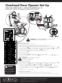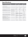
1
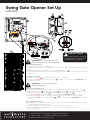
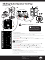
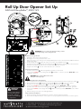
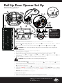
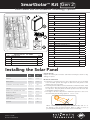
SmartSolar™ Kit Gen 2
Solar Power Kits For Automatic Technology Openers
ACCESSORY PACK
ITEM
1
5
DESCRIPTION
QTY
2 PIN SOLAR SHUNT
1
GEWIS MOUNTING KIT (64805)
2
6
MOUNTING LUGS FOR GEWISS BOX
4
7
SCREW “P” M3.5 X 13
4
8
CABLE 2 CORE R&B X 1.0MM (2.5M)
1
9
NYLON GLAND M16-07B
1
SOLAR BATTERY CABLE KIT (61821)
SOLAR PACK 01 (61783)
3
10
PAN HEAD SCREW M4 X 8
4
11
TAPTITE SCREW “P” M4 X 8
12
BRUSH CARD 2047 L/F HARNESS
1
13
NYLON CABLE GLAND PGB7-07B
2
14
PAN HEAD SCREW M6 X 12
1
15
WASHER 6.4X20.6X1.2 GAL
1
16
WASHER RUBBER 1/16’X1”X3/8”
1
17
TIE MOUNT CM-13 (ADHEISIVE)
4
18
CABLE TIE 4” GT-100M
4
SOLAR PACK 02 (61784)
4
SOLAR PACK 03 (61492) (GDO-8 ONLY)
4
SMARTSOLARTM KIT GEN2
ITEM
DESCRIPTION
QTY
1
SOLAR PANEL - 30 WATT STP030-12/Lb
1
2
BATTERY PACK (2 X 12 Ah)
1
3
CHARGER BOARD (WITH HARNESS)
1
4
ACCESSORY PACK
1
SOLAR PACK 04 (61786)
19
TAPTITE SCREW “P” M3 X 8
4
SOLAR PACK 05 (61787) (GDO-9 ONLY)
20
THRUSS SER HD SCREW “S” M4 X 8
2
21
TAPTITE SCREW “P” M4 X 8
3
22
PCB SUPPORT 76X27
1
Installing the Solar Panel
TOWN
Latitude
(L°)
Panel Angle
(α°)
HOBART
42.5º S
57.5º
MELBOURNE
37.5º S
52.5º
35º S
50º
SYDNEY
33.5º S
48.5º
NEWCASTLE, BROKEN HILL, PORT
AUGUSTA, PERTH
32.5º S
47.5º
BRISBANE, OODNADATTA,
GERALDTON
27.5º S
42.5º
20º S
35º
5º
20º
CANBERRA, ADELAIDE, AlLBANY
TOWNSVILLE, TENNANT CREEK,
PORT HEDLAND
DARWIN
Unpack the Kit
Unpack the Battery Box and the Solar Panel and inspect them for any
damage in transit.
Mount the Solar Panel
a. Determine a mounting point for the solar panel as close as possible
to the intended opener. The length of cable from solar panel to solar
charger must not exceed 5m.
b.The solar panel should be faced to the North for maximum effect. Solar
panel output is directly proportional to the amount of sunlight to which
it is exposed. Thus, the panel should be positioned to the north due
to Australia’s southern location.
c. The angle to tilt the solar panel for maximum exposure to the sun is
determined by the following equation: α° = L° + 15°
L°
α°
Where “α°” is panel’s tilt angle from the horizontal, and “L°” is
the latitude of the mounting location. Refer to table, for a list of
pre-calculated panel angles for major centres in Australia.
Doc # 160035_02
Part # 13345
Released 30/05/14
Swing Gate Opener Set Up
DCB-05V2
7
6
2
9
3
1
8
11
IMPORTANT WARNING!
WARNING! Do not connect the batteries until
you have connected wiring on the charger board.
Do not connect battery or solar panel
polarity incorrectly - this will result in
serious damage to components.
Mount the Charger Board
a. Unplug the Control Box from mains power.
b. Remove the Control Box’s cover, then remove the transformer, EMC board (if fitted) and mains power
cable.
c. Mount the Charger Board inside the cover using four (4) M4x8 screws 11 .
d. Plug the Charger Board’s three wire harness (red/yellow/black) into the DCB-05 board’s “SBC-02”
connector.
Connect the Solar Panel
a. Feed the Solar Panel’s 1 cable through black grommet on the chassis.
b. Connect the red wire to the Charger Board’s 3 “SOLAR+” connector, and the black wire to the
“-SOLAR” connector.
WARNING! The opener will become active
during the following steps.
Mount & Connect the Battery
a. Drill a 16.0mm hole in the Battery Pack enclosure (recommend at the bottom) and fit nylon gland 9 .
b. Mount the Battery Pack 2 using the mounting lugs 6 and screws 7 close to the control box.
c. Feed the 2-core 18awg gauge cable 8 through the Battery Box’s nylon gland 9 .
d. Connect the red wire to the Battery Box’s “+” terminal, and the black wire to the “–” terminal
e. Feed the other end of the 2-core 18awg gauge cable 8 through the drive unit’s black grommet.
f. Connect the red wire to the Charger Board’s 3 “BAT+” connector, and the black wire to the “–BAT”
connector.
Setup and Test the Opener
a. Select Menu 7 on the DCB-05 control board, press “SET”, select Sub Menu 7 (“Battery/Solar”) and enable
using the “OPEN” and CLOSE” buttons.
b. Setup travel limits and transmitters as per the DCB-05V2 instruction manual.
c. Press either “OPEN” or “CLOSE” buttons, or use a transmitter to operate the gate.
d. Refit the Control Box’s cover.
6 - 8 Fiveways Boulevard, Keysborough, VIC, Australia 3173
P: 1300 133 944
E: [email protected]
W: www.automatictechnology.com.au
Sliding Gate Opener Set Up
NeoSliderTMV2
7
6
11
2
9
3
8
WARNING! Do not connect the batteries until you have
connected wiring on the charger board.
IMPORTANT WARNING!
Do not connect battery or solar panel
polarity incorrectly - this will result in
serious damage to components.
1
Mount the Charger Board
a. Unplug the drive unit from mains power.
b. Remove the main cover, then remove the transformer, EMC board (if fitted) and mains power cable.
c. Mount the Charger Board inside the cover using four (4) M4x8 screws 11 .
d. Plug the Charger Board’s three wire harness (red/yellow/black) into the control board’s “SBC-02” connector.
Connect the Solar Panel
a. Feed the Solar Panel’s 1 cable through black grommet on the chassis.
b. Connect the red wire to the Charger Board’s 3 “SOLAR+” connector, and the black wire to the “-SOLAR”
connector.
WARNING! The opener will become active
during the following steps.
Mount & Connect the Battery
a. Drill a 16.0mm hole in the Battery Pack enclosure (recommend at the bottom) and fit nylon gland 9 .
b. Mount the Battery Pack 2 using the mounting lugs 6 and screws 7 close to the opener.
c. Feed the 2-core 18awg gauge cable 8 through the Battery Box’s nylon gland 9 .
d. Connect the red wire to the Battery Box’s “+” terminal, and the black wire to the “–” terminal
e. Feed the other end of the 2-core 18awg gauge cable 8 through the drive unit’s black grommet.
f. Connect the red wire to the Charger Board’s 3 “BAT+” connector, and the black wire to the “–BAT”
connector.
Setup and Test the Opener
a. Select Menu 7 on the control board, press “SET”, select Sub Menu 7 (“Battery/Solar”) and enable using
the “OPEN” and CLOSE” buttons.
b. Setup travel limits and transmitters as per the slider instruction manual.
c. Press either “OPEN” or “CLOSE” buttons, or use a transmitter to operate the gate.
d. Refit the main cover.
B&D Doors is a division of B&D Australia Pty Ltd
P: 13 62 63
W: www.bnd.com.au
Roll Up Door Opener Set Up
GDO-6V4 EasyRoller®, RDO-1V3
7
6
2
11
9
3
SOLAR
SHUNT
8
5
WARNING! Do not connect the batteries until you have
connected wiring on the charger board.
1
Mount the Charger Board
a. Unplug the drive unit from mains power.
b. Disengage motor using manual release cord.
c. Remove the main cover, timing cover and light diffuser, then remove the transformer, EMC board and
mains power cable.
d. Fix the Charger Board 3 under the timing cover using four (4) M4x8 screws 11 .
e. Feed the four wire cable attached to the Charger board 3 through the opening, then connect the three
wire harness (red/yellow/black) into the control board’s “SBC-02” connector.
f. Plug the solar shunt 5 onto the control board’s “J13” connector.
Connect the Solar Panel
a. Feed the Solar Panel’s 1 cable through black grommet on the chassis.
b. Connect the red wire to the Charger Board’s 3 “SOLAR+” connector, and the black wire to the
“-SOLAR” connector.
WARNING! The opener will become active
during the following steps.
IMPORTANT
WARNING!
Do not connect battery
or solar panel polarity
incorrectly - this will
result in serious damage
to components.
Mount & Connect the Battery
a. Drill a 16.0mm hole in the Battery Pack enclosure (recommend at the bottom) and fit nylon gland 9 .
b. Mount the Battery Pack 2 using the mounting lugs 6 and screws 7 close to the opener.
c. Feed the 2-core 18awg gauge cable 8 through the Battery Box’s nylon gland 9 .
d. Connect the red wire to the Battery Box’s “+” terminal, and the black wire to the “–” terminal
e. Feed the other end of the 2-core 18awg gauge cable 8 through the drive unit’s black grommet.
f. Connect the red wire to the Charger Board’s 3 “BAT+” connector, and the black wire to the “–BAT”
connector.
g. Refit the timing cover, main cover and light diffuser.
Setup and Test the Opener
a. Setup travel limits and code transmitters as per the openers instruction manual.
b. Press either the Operate button on the opener or use a programmed transmitter to test the opener.
6 - 8 Fiveways Boulevard, Keysborough, VIC, Australia 3173
P: 1300 133 944
E: [email protected]
W: www.automatictechnology.com.au
Roll Up Door Opener Set Up
GDO-8 EasyRoller®
13
12.5mm
Drilled Hole
13
14
15
16
3
17
20
18
30
12
1
2
8
6
9
IMPORTANT
WARNING!
Do not connect battery
or solar panel polarity
incorrectly - this will
result in serious damage
to components.
7
Insert the Solar Panel’s Wires
a. Unplug the drive unit from mains power.
b. Remove the controls cover and chassis enclosure, then remove the transformer and EMC board.
c. Remove the mains power cable, then fit a nylon gland 13 to its hole in the chassis. Feed the
Solar Panel’s 1 cable through this gland.
d. Fill the transformer’s screw hole by using the rubber washer 16 , metal washer 15 and M6x10 screw 14 .
WARNING! Do not connect the batteries until you have connected wiring on the charger board.
Mount the Battery Box
a. Drill a 12.5mm hole in the chassis enclosure as shown above.
b. Fit a nylon gland 13 to this hole.
a. Drill a 16.0mm hole in the Battery Pack enclosure (recommend at the bottom) and fit nylon gland 9 .
b. Mount the Battery Pack 2 using the mounting lugs 6 and screws 7 close to the opener.
c. Feed the 2-core 18awg gauge cable 8 through the Battery Box’s nylon gland 9 and the nylon gland
openers chassis.
d. DO NOT CONNECT THE WIRES to the Charger Board or battery terminals.
13
in the
WARNING! The opener will become active during the following steps.
Mount & Wire the Charger Board
a. Secure the adhesive mounts 17 to the Charger Board with cable ties 18 . Affix the Charger Board 3 inside the
chassis enclosure above the 12.5mm drilled hole.
b. Unscrew and remove the four-wire harness from the Charger Board. Replace with the two-wire (red/yellow) harness
12 , connecting wires as shown.
c. Plug the two wire (red/yellow) harness 12 into the control board’s “24vac supply” connector.
d. Connect the red wire to the Charger Board’s “SOLAR+” connector, and the black wire to the “–SOLAR”
connector.
e. Connect the 2 core cable to the battery by; connecting the red wire to the Battery Box’s “+” terminal, and the
black wire to the “–” terminal.
f. Refit covers and chassis enclosures to the opener.
Setup and Test the Opener
a. Setup travel limits and code transmitters as per the GDO-8 instruction manual.
b. Press either the Operate button on the opener or use a programmed transmitter to test the opener.
B&D Doors is a division of B&D Australia Pty Ltd
P: 13 62 63
W: www.bnd.com.au
Overhead Door Opener Set Up
GDO-9V2 GEN2 Enduro, GDO-9V3 GEN2 Dynamo,
SDO-2V2 CAD P Diamond & SDO-3V2 CAD S
21
3
7
6
20
22
2
9
8
SOLAR
SHUNT
WARNING! Do not connect the batteries until you have
connected wiring on the charger board.
5
1
Mount the Charger Board
a. Unplug the drive unit from mains power.
b. Remove the screws and swing open the main cover and remove the light diffuser.
c. Remove the transformer, EMC board (if fitted) and mains power cable.
d. Fit the PCB Support 22 to the base plate under the timing assembly using the two (2) M4 x 8 screws 20 .
e. Fix the Charger Board 3 onto the PCB Support using three (3) Taptite M4x8 screws 21 .
f. Feed the four wire cable attached to the Charger board 3 through the opening, then connect the three
wire harness (red/yellow/black) into the control board’s “SBC-02” connector.
g. Plug the solar shunt 5 onto the control board’s “J13” connector.
Connect the Solar Panel
a. Feed the Solar Panel’s 1 cable through black grommet on the chassis.
b. Connect the red wire to the Charger Board’s 3 “SOLAR+” connector, and the black wire to the
“–SOLAR” connector.
WARNING! The opener will become active
during the following steps.
IMPORTANT
WARNING!
Do not connect battery
or solar panel polarity
incorrectly - this will
result in serious damage
to components.
Mount & Connect the Battery
a. Drill a 16.0mm hole in the Battery Pack enclosure (recommend at the bottom) and fit nylon gland 9 .
b. Mount the Battery Pack 2 using the mounting lugs 6 and screws 7 close to the opener.
c. Feed the 2-core 18awg gauge cable 8 through the Battery Box’s nylon gland 9 .
d. Connect the red wire to the Battery Box’s “+” terminal, and the black wire to the “–” terminal
e. Feed the other end of the 2-core 18awg gauge cable 8 through the drive unit’s black grommet.
f. Connect the red wire to the Charger Board’s 3 “BAT+” connector, and the black wire to the “–BAT”
connector.
g. Refit the main cover and light diffuser.
Re-setup and Test the Opener
a. Setup travel limits and code transmitters as per the openers instruction manual.
b. Press either the Operate button on the opener or use a programmed transmitter to test the opener.
6 - 8 Fiveways Boulevard, Keysborough, VIC, Australia 3173
P: 1300 133 944
E: [email protected]
W: www.automatictechnology.com.au
Specifications
SmartSolar™V2 Technical Specifications*
Garage Door
Slider
Swing Gate
Load Voltage
24
24
24
Load Continuous Current
3 - 5A
5A
5 - 10A
Number of Cycles per Day
10
10
10
Average Cycle Time (Opening and Closing)
40 seconds
90 seconds
72 seconds
- Without P.E. Beams
100mA
100mA
100mA
- With P.E. Beams
180mA
180mA
180mA
Max. Standby Current
- With 2 x P.E. Beams
Average total consumption current per day
260mA
- Without P.E. Beams
2.75 - 3Ah
3.7Ah
3.4 - 4.4Ah
- With P.E. Beams
4.66 - 4.8Ah
5.55Ah
5.31 - 6.3Ah
- With 2 x P.E. Beams
Average total consumption current per hour
7.23 - 8.23Ah
- Without P.E. Beams
0.11 - 0.13A
0.16A
0.14 - 0.18A
- With P.E. Beams
0.194 - 0.2A
0.23A
0.22 - 0.26A
- With 2 x P.E. Beams
0.3 - 0.343A
Recommended storage battery
capacity / voltage
10.5Ah/24v
12Ah/24V
12 - 18Ah/24V
Wire Gauge and Length from Battery to
Charger board (max)
18AWG, 3m
18AWG, 3m
18AWG, 3m
Solar panel average rated output
generation time per day (winter months)
4 hours
4 hours
4 hours
Solar Panel Output voltage / current
18V / 1.19A
18V / 1.75A
18V / 1.75A
B&D Doors is a division of B&D Australia Pty Ltd
P: 13 62 63
W: www.bnd.com.au
Important Safety Instructions
WARNING!
•
•
•
•
•
•
ELECTROCUTION!
DO NOT short the output of batteries. Serious personal injury and/or property damage
can result from failure to follow this warning
DO NOT connect battery wires incorrectly to solar charger - Observe the polarity
carefully!
During charging and discharging cycles the lead-acid batteries may release explosive
gases. Ensure that the area around the batteries is well ventilated
Take care not to allow any metal objects to make contact with the positive and negative
terminals. This will short circuit the battery causing sparks and possible damage to the
battery, the solar charger module, or even cause an explosion.
DO NOT connect the battery box directly to solar panel.
Install the solar charger kit in a location where it is out of reach of children.
•
•
•
The solar charger and battery box unit should be installed away from sprinkler systems.
DO NOT immerse in water or spray directly with a hose or other device.
DO NOT conect any other source of power to the opener if a SmartSolarTM kit is
installed.
Muscular strain
•
Practice correct lifting techniques
Fall from ladder
•
•
•
•
•
Ensure ladder is the correct type for job.
Ensure ladder is on flat ground.
Ensure user has 3 points of contact while on ladder.
DO NOT handle damaged or leaking batteries
Wear appropriate protective clothing and avoid touching your eyes after working with
batteries..
The solar charger kit contains sealed lead-acid batteries that must be disposed of
properly at the end of their useful life.
DO NOT bend or drop the solar panel.
DO NOT use the SmartSolar™ kit to power other devices - it is specifically designed for
Automatic Technology door and gate openers and some accessories only.
CAUTION:
Burns
•
Damage
•
•
Warranty and Exclusion of Liability
1. This warranty is an addition to any non-excludable conditions or warranties that
are implied into this contract by relevant statute, including the Trade Practices Act
1974 (Cwth).
2. Subject to all of the matters set out below, Automatic Technology Australia Pty Ltd
(“ATA”) warrants:
SmartSolar™ kit for twelve (12) months from the date of purchase (specified in the
sales docket receipt) as free of any defects in material and workmanship.
3. This warranty applies only where the purchaser:
a. immediately notifies ATA or the retailer of the alleged defect;
b. returns the product to the retailer; and
c. presents the relevant sales docket and this warranty document to the retailer
to confirm the date of purchase.
4. Except for this warranty, ATA gives no warranties of any kind whatsoever (whether
express or implied), in relation to the product, and all warranties of whatsoever kind
relating to the product are, to the extent permissible by statute, hereby excluded.
5. To the extent permissible by statute, ATA disclaims any liability of whatsoever
nature in respect of any claim or demand for loss or damage which arises out of:
a. accidental damage to or normal wear and tear to the product or to the product’s
components;
b. any cost relating to damage resulting from wear and tear;
c. loss or damage due to theft, fire, flood, rain, water, lightning, storms or any
other acts of God;
d. maximum operating force exceeding 15kg (150N) when moving the door or
gate manually to the open or closed position;
e. door surface area and/or weight exceeding 16.5m2 and 100kg respectively;
f. residential gate weight exceeding 400kg;
g. door or gate not in safe and correct working order and condition;
h. evidence of unauthorised repairs;
i. any cost relating to damage caused by misuse, negligence or failure to maintain
the equipment in a proper working order as per clauses (d) through (i);
j. installation, adjustment or use which is not in accordance with the instructions set
out in installation instruction manual
k. attempted or complete modification or repairs to the product carried out by a
person who is not authorised or has not been trained by ATA to carry out such
modification or repairs;
l. faulty or unsuitable wiring of structure to which the product is fixed or connected;
m. damage caused by insects;
n. loss or damage to any property whatsoever or any loss or expense whatsoever
resulting or arising there from or any consequential loss;
o. any cost or expense arising due to manufacturer recall of any product;
p. any cost or expense due to negligence of the approved service provider;
q. installation of a residential garage door or gate opener in a commercial or
industrial situation or a non-single residential dwelling.
6. ATA’s liability under this warranty is limited, at ATA’s absolute option, to replacing or
repairing the product which ATA, in its unfettered opinion, considers to be defective
either in material and/or workmanship or to credit the dealer with the price at which
the product was purchased by the dealer.
7. This warranty does not extend to cover labour for installation.
8. This warranty is limited to Return-to-Base (RTB) repair and does not cover labour for
on-site attendance.
9. This warranty is void if the Product is not returned to the manufacturer in original or
suitably secure packaging.
10.This warranty is only applicable for repairs to the product carried out within Australia.
11.This warranty does not cover consumable items including globes, batteries and fuses.
12.This warranty is not transferable.
13.Where the Product is retailed by any person other than ATA, except for the warranty
set out above, such person has no authority from ATA to give any warranty or
guarantee on ATA’s behalf in addition to the warranty set out above.
B&D Doors is a division of B&D Australia Pty Ltd
ABN 25 010 473 971
6 - 8 Fiveways Boulevard, Keysborough, VIC, Australia 3173
P: 1300 133 944
E: [email protected]
W: www.automatictechnology.com.au
B&D Doors, 34-36 Marigold St, Revesby, NSW, 2212
P: 13 62 63
E: [email protected]
W: www.bnd.com.au
© March 2014 Automatic Technology (Australia) Pty Ltd. All rights reserved. No part of this document may be reproduced without prior permission. In an ongoing
commitment to product quality we reserve the right to change specification without notice. E&OE.