1
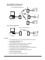
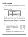
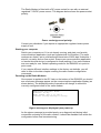
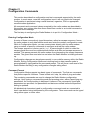
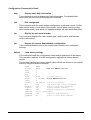
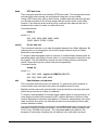
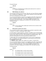
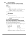
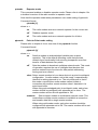
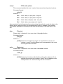
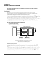
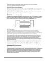
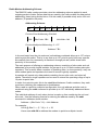
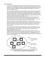
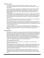
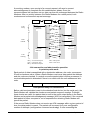
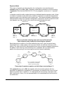
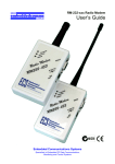
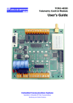
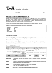
RMX232 Radio Modem
User’s Guide
N11391
Embedded Communications Systems
Specialists in Embedded RF Data Communications,
Monitoring and Control Systems
Copyright Notice
Copyright
©2006 by Embedded Communications Systems Pty Ltd. All rights reserved. Under the
copyright laws, this manual cannot be reproduced in any form without the prior written
permission of Embedded Communications Systems. No patent liability is assumed,
with respect to the use of the information contained herein.
embeddedcomms RMX232 Radio Modem User’s Guide
First Edition November 2006 (Covers firmware version 1.00a)
Disclaimer
This manual has been validated and reviewed for accuracy. The instructions and
descriptions it contains are accurate for the embeddedcomms RMX232 Radio
Modem at the time of this manuals publication. However succeeding products and
manuals are subject to change without notice. Embedded Communications Systems
assumes no liability for damages incurred directly or indirectly from errors, omissions
or discrepancies between the radio modem and the manual.
These radio devices may be subject to radio interference and may not function as
intended if interference is present. Systems should be designed to tolerate such
interference.
RF transmission power levels are subject to regulatory approval in countries:
consequently, it is possible that some radio modem functionality is not provided in your
country.
Radio and EMC Regulations
The user of RMX232 Radio Modems must satisfy all relevant EMC and other
regulations applicable in the intended country of use.
The radio modules used in the RMX232 range of radio modems are type approved to
EN 300 220-3 and EMC conformant to EN 301 493-3.
Problem Reporting and Feedback
To report operational problems, documentation problems, suggested product
enhancements or obtain technical assistance please email technical support at
[email protected]. Please include in all email correspondence your
name, company, modem type, modem serial number and firmware version.
All information supplied to Embedded Communications Systems will be treated in the
strictest of confidence.
User’s Guide
Page i
Contents
Chapter 1 Introduction .......................................................................................................1-1
About this Manual ..............................................................................................................1-1
The RMX232 Radio Modem ..............................................................................................1-1
Features.............................................................................................................................1-2
Chapter 2 Installation and Operation ................................................................................2-1
Serial Interface...................................................................................................................2-1
Connecting for the First Time.............................................................................................2-1
Front Panel Indicator Lights ...............................................................................................2-3
Mounting the Radio Modem...............................................................................................2-3
Positioning the Radio Modem ............................................................................................2-4
Potential RF Interference ...................................................................................................2-4
Operating Problems ...........................................................................................................2-4
Chapter 3 Configuration Commands ................................................................................3-1
Entering Configuration Mode .............................................................................................3-1
Command Format ..............................................................................................................3-1
Configuration Commands in Detail ....................................................................................3-2
Chapter 4 Modem Operation Explained ............................................................................4-1
Flow Control.......................................................................................................................4-1
Serial Port Flow Control ..................................................................................................4-1
XON/XOFF Flow Control (Software) ...............................................................................4-2
RTS/CTS Flow Control (Hardware).................................................................................4-2
No Flow Control ..............................................................................................................4-2
Radio Modem Port Flow Control .....................................................................................4-2
Radio Modem Addressing Scheme ...................................................................................4-3
On-Air Data Speed ............................................................................................................4-4
DTR Power Control............................................................................................................4-5
Operating Modes ...............................................................................................................4-5
Acknowledged Point-to-Point ..........................................................................................4-5
Acknowledged Point to Multipoint ...................................................................................4-7
Broadcast Multidrop ........................................................................................................4-8
MultiMaster Mode ...........................................................................................................4-8
Repeater Mode ...............................................................................................................4-9
Diagnosing Network Problems Using Ping Test ..............................................................4-10
Performing Site Reliability Tests Using Radar Test .........................................................4-10
User’s Guide
Page ii
Chapter 5 Connecting the Radio Modem..........................................................................5-1
Serial Pinouts.....................................................................................................................5-1
Connecting to a PC............................................................................................................5-2
Two Wire Simplex Interface ...............................................................................................5-3
Three Wire Half Duplex Interface.......................................................................................5-3
Connecting to other DTE and DCE Equipment..................................................................5-4
Chapter 6 Specifications ....................................................................................................6-1
Chapter 7 Product Version Information ............................................................................7-1
Version Information............................................................................................................7-1
Firmware Version Numbering Scheme ..............................................................................7-1
Chapter 8 Modification History..........................................................................................8-1
Bug Fixes & Change History..............................................................................................8-1
User’s Guide
Page iii
Chapter 1
Introduction
About this Manual
This manual has been written for the RMX232 range of low cost short range modems
license exempt radio modems.
A list of the Radio Modems currently covered by this manual is included in the
appendix:
The generic reference of RMX232 will be used throughout this manual when referring
to any one of the RMX232-xxx modem variants mentioned above. Specific
information relating to a specific radio modem type will be noted by using the full radio
modem name.
The RMX232 Radio Modem
The RMX232 Radio Modem provides the capability of a short range, reliable wireless
point-to-point and point-to-multipoint RF data communications link.
The RMX232 can be used in a variety of data communications applications that
require a simple to use invisible data link. The radio modem is designed to interface to
a variety of host devices. These devices include computers, PDA’s, personal
organisers, PLC’s, data loggers, SCADA devices and intelligent control & transducer
systems.
The serial data transferred over the radio link is not altered; the output serial data
stream is the same as the input serial data stream. The radio modems provide a twoway data communications links, where each unit can accept serial data and also
output serial data.
The RMX232 radio modems are fully self-contained units, requiring only an external
7VDC to 15VDC power source to operate. The radio modules used in the radio
modems have been selected to meet the requirements of unlicensed operation in the
international ISM bands, and are therefore acceptable for use in many countries.
User’s Guide
Introduction 1-1
Point-to-Multipoint Configuration and
Broadcast Multi-drop Configuration
Point-to-Multipoint Radio Link
RMX232
RS232
c:\
RMX232
RMX23
2
RS232
RS232
Master Unit
RMX232
RS232
Point-to-Point Configuration
Point-to-Point Radio Link
c:\
RMX232
Local Host
RMX232
RS232
RS232
Remote Host
Features
•
•
•
•
•
•
•
•
•
•
•
•
User’s Guide
Acknowledged Point-to-Point and Point-to-Multipoint RF networks.
Acknowledged MultiMaster mode
Broadcast Multidrop mode
User selectable serial DTE speeds (600 to 115200bps).
Serial protocol format is 8 data/1 stop/no parity.
Selectable flow control of hardware/software/none.
On-air data encryption, error checking and data acknowledgements.
Low operating current. Auto standby mode.
Configurable as a network repeater for extended range.
Built-in configuration software.
Remote over-air configuration.
Built in configuration and diagnostic functions.
Introduction 1-2
Chapter 2
Installation and Operation
This chapter describes basic connection procedures and operation. It also covers the
front panel indicator lights and physical mounting and positioning of the radio modem.
Serial Interface
The RMX232 radio modem interfaces to external DTE equipment using a 9 way D
type female connector. The serial interface is configured as DCE equipment with the
pin out shown in the table below.
Pin
Name
DCE Function
2
RXD
Receive Data (out)
3
TXD
Transmit Data (in)
4
DTR
Data Terminal Ready (in)
5
SG
Signal Ground
7
RTS
Ready To Send (in)
8
CTS
Clear To Send (out)
The serial protocol supported by the radio modem is fixed at 8 data bit, 1 stop bit and
no parity. Flow control can be user selected as either hardware (RTS/CTS), software
(XON/XOFF) and none. The serial baud rate is also user configurable and supports
the following rates: 600, 1200, 2400, 4800, 9600, 14400, 38400, 57600, and 115200.
When operating the radio modem at a DTE baud rate greater than the configured onair data throughput, data received by the radio modem will be buffered internally. At
the higher DTE baud rates either hardware or software flow control should be used to
prevent receive buffer overflows in the radio modem.
Connecting for the First Time
Follow the steps below to connect the RMX232 radio modem to your computer.
Connecting to your computer or terminal equipment
Connect the supplied 9 way data cable to the radio
modem and to a suitable serial data port on your
computer. If the serial data port on your computer is a
25 way connector, you will require a suitable 9 way to
25 way adapter. The D9 DTE (host) to D9 DCE (radio
modem) pin connection diagram is shown in the
diagram opposite.
Supplying power to the Radio Modems
The RMX232 radio modem requires a 9-15VDC power source to operate. A
reliable external power source is strongly advised when running the radio
modem continuously.
User’s Guide
Installation 2-1
The Radio Modem is fitted with a DC power socket for use with an external
regulated 7-15VDC power source. The diagram below shows the power socket
polarity.
Power socket type and polarity.
Contact your distributor if you require an appropriate regulated mains power
supply to suit.
Starting your computer
Switch your computer on if it is not already running, and start your favorite
communications application (such as Hyperteminal for Windows). The radio
modems are factory set to a default serial baud rate of 9600 bps, 8 data bits, 1
stop bit, no parity and no flow control. Ensure your communication application
or remote terminal device is configured to these settings. Your radio modems
are now ready for use. Default operating mode for the RMX232 is in point-topoint mode.
If you require different interface settings to the factory set defaults, you will
need to refer to the later chapter covering the radio modem configuration
commands.
Powering up the Radio Modems
Once power is applied to the DC Jack on the bottom of the RMX232 you should
see a welcome message appear on the communications application display (as
shown below). The displayed mode of operation will change to reflect the
currently configured mode of the radio modem.
RMX232-xxx UHF Radio Modem
Firmware: V2.xxy
Mode: Modem. Unit 0 at site 0
(Disable startup message in setup)
Signon message as displayed upon power-up
As the signon message is provided purely as a diagnostic aid during initial
connection and setup of the radio modem, it should be disabled from within the
configurator before final commissioning.
User’s Guide
Installation 2-2
The status LED indicator on the front of the radio modem should be showing 1
short pulse every 2 seconds (approximately). This indicates the radio modem is
in standby mode. The receive LED indicator (green) will also be flashing
regularly indicating it is listening for radio transmissions.
Sending Serial Data
Assuming both radio modems are connected and operating correctly, you are
now ready to send some data. Ensure the two radio modems are spaced with
at least 5 or more metres between them.
Entering keystrokes in the communications application on one computer should
result in those characters appearing in the communications application on the
remote computer.
Front Panel Indicator Lights
The radio modem has 3 indicator LEDs on the front panel. These LEDs are used to
give the radio modem operator an indication of the current state of operation of the
Radio Modem.
Indicator
RX/TX
RX/TX
RX/TX
RX Data
Status
Status
Status
Status
Status
State
Red
Green steady
Green flash
Red
Single pulsing
Double pulsing
On/Off (0.5 sec)
On/Off (2 secs)
On
Meaning
Radio transmitting.
Link established and listening for data.
Radio in standby mode waiting to establish a link.
Radio receiving data.
Radio Modem is active but no link is established.
A link to a Remote device has been established
Attempting to connect to a remote Radio Modem.
Low battery indication. (Two second flash rate)
Radio Modem is in setup and configuration mode.
Mounting the Radio Modem
Each radio modem is supplied with two lengths of adhesive backed Velcro. This
Velcro can be used to mount the radio modem on a wall, window, carpet covered
divider, or onto anything the hooked Velcro itself, or the Velcro adhesive will adhere to.
User’s Guide
Installation 2-3
Positioning the Radio Modem
In order to achieve maximum operational reliability and range from your radio modems
it is important to reduce the possible effects of RF interference on them.
Each radio modem has an antenna protruding from the top of the case. This antenna
is used for both receiving and transmitting data. This antenna will provide adequate
range and reliability for most applications. However, in order to improve the range and
reliability of the radio modem RF link it is advised that the following guidelines be
understood and implemented where possible.
•
Free space around the antenna is as important as the antenna itself.
•
The optimum orientation of the antenna is directly upward.
•
Do not mount the radio modem directly on or against metal surfaces. Close
proximity to metal surfaces can cause degradation and reflection of the radio
signal which will severely undermine the performance of the radio modem.
•
Ensure the antenna is kept away from potential sources of RF interference such
as electrical wiring, transformers, batteries and other items of electronic
equipment.
•
Where possible ensure the Radio Modems are placed well above head height.
The higher the better!
It is wise to try different locations and positions for the radio modem before
permanently mounting it. When trying out different positions, if you are holding the
radio modem, do not hold it by the antenna and keep it well away from your body
(preferably above your head) in order to reduce potential shielding of the radio signal.
A few centimetres difference in the location of the radio modem can sometimes
(depending on surrounding furniture, walls and equipment) make all the difference
between a reliable link and a link that is prone to constant errors and lost packets.
Potential RF Interference
The radio modem is a sensitive piece of electronic equipment, which may from time to
time be affected by other radio transmitting devices operating in close proximity. Such
devices include microwave ovens, mobile phones and radio transmitter. If erratic
behaviour or erroneous data is observed, try turning off the source of interference or
moving the radio modem away from that device.
Direct mounting of the radio modems to the case of computers, printers and monitors
is not advised due to potential RF interference.
A word of caution: Computers, printers and other microprocessor based equipment
are renown for being big generators of RF interference. Ensure the radio modem is
situated as far away from these devices as is practically possible. Keep in mind
however that running an excessively long serial cable to the radio modem can produce
unreliable communications between the terminal equipment and radio modem.
Operating Problems
A number of factors can affect the successful operation of a Radio Modem link. Most
of the problems are related to either radio interference or an inadequate radio path.
Prior to deploying a new installation, a bench test of the system is highly
recommended as a method of eliminating basic operational and system configuration
User’s Guide
Installation 2-4
problems. Inadequate performance from the bench test may require fine tuning of the
configuration parameters.
It is recommended that for any new site installation a radio site test be performed. This
can be accomplished using the ping and radar diagnostic functions built in to the
Radio Modem. The diagnostic functions are explained in detail later.
If an installed system exhibits poor performance, both the radio path and possible
interference sources should be checked. Again the diagnostic functions ping and radar
can be used to check for these conditions. A high failure rate reported by the radar test
may indicate either the presence of interference or an inadequate radio path.
User’s Guide
Installation 2-5
Chapter 3
Configuration Commands
This section describes the configuration and test commands supported by the radio
modem. In most cases, once the configuration is set it will not need to be changed.
Configuration is performed using a serial terminal, organiser, PDA or appropriate
communication application.
All commands and command values accepted by the radio modem are described in
this section; any entries other than those listed here results in an invalid command or
argument error message.
The first step to configuring the Radio Modem is to put it in Configuration Mode…
Entering Configuration Mode
A series of three consecutively typed characters, called an escape sequence, forces
the radio modem to exit data transfer mode and enter the modem configuration mode.
While in Configuration Mode, you can communicate directly with the radio modem
using a number of specific commands to configure and test the radio modem.
The escape sequence is factory set to ‘+++’. A pause length of which is called the
escape guard time must be completed both before and after and escape sequence is
entered. This pause prevents the radio modem from interpreting the escape sequence
as data. The guard time must also be met when the Radio Modem is initially powered
up.
Configuration changes are stored permanently in non-volatile memory within the Radio
Modem. Exiting Configuration Mode and returning back to data transfer mode is
accomplished by typing exit at the command prompt. This will force a soft reset of the
Radio Modem resulting in any configuration changes taking effect.
Command Format
Configuration Mode supports two basic types of commands. The first are commands
that perform specific functions. These include exit, help, list, default, ping and radar.
The remaining commands are used to change the Radio Modem configuration
settings. Upon typing a command keyword and pressing enter, without specifying any
parameters, the current setting is displayed. However if the command is typed and
parameters are specified, the parameters and data are verified before the specified
setting is updated.
All alphabetical characters typed in configuration command mode are converted to
lower case before being interpreted by the configurator. Thus commands can be typed
using either upper or lower case.
User’s Guide
Configuration Commands 3-1
Configuration Commands in Detail
help
Display basic help information
This command is used to display brief help information. For detailed help
information the manual should always be consulted!
exit
Exit configurator
This command exits the radio modem configuration mode and returns it to the
data transfer mode. A soft reset of the modem occurs when returning to the
data transfer mode, after which the updated settings will take immediate effect.
ser
Display the unit serial number
This command displays the radio modem type, serial number and firmware
version information.
list
Display the current Radio Modem configuration
This command displays a list of the current radio modem user configured
settings.
default
Load factory settings
This command loads the configuration stored and programmed at the factory.
This operation replaces all of the configuration options with factory default
values.
The list below shows the factory default values which are written to non-volatile
memory using the default command:
baud
airspd
unit
site
hop
flow
dlytx
retry
ctime
dtr
batmon
signon
remote
cmdchar
rptmode
ptpmode
User’s Guide
9600
9600
2400 for RMX232-151/173
0
0
0
(no flow control)
none
4 (x10ms) 25 for RMX232-151/173
5
10 (secs) (connection timeout)
off
(DTR power down control disabled)
off
(battery monitoring disabled)
on
(signon message enabled)
off
(remote configuration disabled)
43(+) 100(x10ms)
(repeater mode disabled)
off
on
(point-to-point mode enabled)
Configuration Commands 3-2
baud
DTE baud rate
This command sets the host interface (DTE) baud rate. The changed baud rate
will take effect after leaving the configurator using the exit command.
Using a DTE baud rate, with no flow control, greater than the radio through-put,
you should be aware of the 96 byte serial internal receive buffer of the radio
modem. If the internal serial receive buffer overflows then data will be lost. If
hardware flow control is used, no data will be lost.
Command format
baud [n]
where: n =
600, 1200, 2400, 4800, 9600, 14400
19200, 38400, 57600, 115200
airspd
On-air data rate
This command sets the on-air data throughput between two Radio Modems. By
reducing the on-air throughput, the air-time usage between a pair of Radio
Modems is also reduced.
To improve data throughput within a network of multiple Radio Modem pairs all
operating within radio range of each other, it is recommended to drop the on-air
throughput. This will effectively reduce the rate of data collisions and packet
retries, thus improving the overall network interoperability.
Command format
airspd [n]
where: n =
600, 1200, 2400 – Applies to RMX232-151/173
600, 1200, 2400, 4800, 9600
unit
Radio Modem unit address
This command sets the device unit address. To permit two radio modems to
communicate they must have the same unit address and site code.
Multiple modem pairs can operate within close proximity by ensuring each pair
within the group have a unique unit address.
To improve interoperability of multiple radio modem pairs in close proximity, all
units support a listen before transmit (LBT) collision detection. Before a radio
modem attempts to transmit a data packet, it listens for transmission from other
radio modems. Only when no other device pairs are transmitting will the radio
modem transmit its data.
It is recommended that this command is not used to continually change the unit
address in a point-to-multipoint system, as this EEPROM memory location has
a life of only 100,000 write cycles. The command addr is provided for the
purpose of continually changing the unit address, site code and hop count.
User’s Guide
Configuration Commands 3-3
Command format:
unit [n]
where: n =
[0-15] The unit address that a modem pair must be set to in order for
them to communicate.
site
Radio Modem site address
This command sets the device site code. Each site code can effectively support
up to 16 different unit addresses. For two radio modems to communicate they
must have matching unit and site codes.
It is recommended that this command is not used to continually change the site
code in a point-to-multipoint system, as this EEPROM memory location has a
life of only 100,000 write cycles. The command addr is provided for the
purpose of continually changing the unit address, site code and hop count.
Command format:
site [n]
where: n =
[0-7] The site code that a modem pair must be set to in order for them
to communicate.
hop
Data packet repeater hop count
This command sets the number of repeater hops a packet is required to make
in order for it to reach it’s destination radio modem.
As each packet is retransmitted by a repeater, the packet count is decremented
by one, until the packet reaches a hop count of zero. A repeater, upon receiving
a packet with a hop count of zero, will immediately discard the packet. This
prevents a data packet from bouncing around a network forever.
A radio modem will not accept a data packet if it’s hop count is anything but
zero. If a repeater is not required between to radio modems, then this value
should always be set to zero.
The RMX232-151/173 VHF radio modems only support 1 repeater hop.
It is recommended that this command is not used to continually change the hop
count in a point-to-multipoint system, as this EEPROM memory location has a
life of only 100,000 write cycles. The command addr is provided for the
purpose of continually changing the unit address, site code and hop count.
Command format:
hop [n]
where: n =
User’s Guide
0
No repeater hops to reach remote modem
1
One repeater hops to reach remote modem
2
Two repeater hops to reach remote modem
3
Three repeater hops to reach remote modem
Configuration Commands 3-4
addr
Updates local memory unit, site and hop values
This command sets the RAM based values for the unit address, site code and
optionally the hop count.
The command is provided in order to support continual programmatic changing
of the unit address, site code and hop count in an acknowledged point-tomultipoint system.
The command, if used without parameters results in an argument error.
Entering valid parameters results in a period (“.”) being returned, to indicate
success, then the configurator is exited immediately. It can be assumed the
modem is ready to accept serial data after the period has been received.
Please refer to chapter 4 for an overview of using the addr function.
Command format:
addr n [h]
where: n =
0-127 The unit number and site code specified as a single number in the
range specified. This parameter is not optional and must be given.
The value can be used as a single value, thus addressing up to
128 remote units. This effectively combines the unit number and
site code.
Refer to section
where: h =
[0-3] This optional parameter sets the number of repeater hops to
reach the remote unit
The RMX232-151/173 VHF radio modems only support 1 repeater hop.
flow
Set the local flow control method
This command sets the local flow control between the host computer (DTE) and
the radio modem.
Command format:
flow [s]
where: s =
User’s Guide
none
Flow control is disabled
hw
Enables RTS/CTS flow control (hardware)
sw
Enables XON/XOFF flow control (software)
xon n
Sets the XON character to value n
xoff n
Sets the XOFF character to value n
Configuration Commands 3-5
dtr
DTR Control
This command interprets how the radio modem responds to the state of the
DTR signal and changes to the DTR signal. If the host device (DTE) interface
does not provide a DTR signal then this setting should always be set to off.
When DTR control is set to on and the DTR signal is not active, the Radio
Modem enters a power saving shutdown state. Upon the DTR signal becoming
active, the Radio Modem will power up, perform a reset and be ready to receive
data. The Radio Modem will continue to remain in the powered state while DTR
remains active.
Command format:
dtr [s]
where: s =
on
The state of the DTR signal will determine the power-on state of
the radio modem.
off
The state of the DTR signal is ignored and the radio modem
remains always on in standby mode.
batmon
Battery monitoring
This command enables or disables monitoring of the battery voltage level.
When battery monitoring is enabled, if the battery level falls below a threshold
of approximately 5.75 volts, the modem status indicator will begin to flash
slowly with a 1 second duty cycle.
Regardless of whether battery monitoring is on or off, if the battery voltage
drops to below 5.0V the radio modem will enter a reset state and cease to
function, until the battery is replaced.
Command format:
batmon [s]
where: s =
ctime
on
The voltage level of the battery is monitored.
off
Battery voltage level monitoring is disabled.
Connection Timeout Period
This command sets the period the radio modem stays connected in an always
listening state, prior to entering low power standby mode.
Provided there is no serial data to be sent, the radio modem will delay for the
set period (1 to 60 seconds) before entering the lower power standby mode.
Command format:
ctime [n]
where: n =
[1..60] The duration, in seconds, prior to the radio modem entering the
standby mode.
User’s Guide
Configuration Commands 3-6
dlytx
Delay data packet transmissions
This command is used to set the delay between the last serial character
received by the radio modem and the next packet of data sent from the radio
modem.
Radio network traffic is reduced by delaying packet transmissions until there is
either a timeout of this delay period or there is enough data in the serial receive
queue to transmit a complete full length data packet.
The delay has no effect on the speed of transmission when data is being
streamed through the radio modem. It does however assist in lowering the
transmission rate for non-streaming data such as typing on a keyboard.
Command format:
dlytx [n]
where: n =
[4-255]
This value is in units of 10 milliseconds. Therefore a value
of 4 is equivalent to 40ms, while a value of 255 corresponds to a
2.55 second delay. The default value is adequate for most
applications.
retry
Data packet retry attempts
This command sets the number of retry attempts the radio modem makes to get
a packet sent to the remote unit.
A data packet or it’s return acknowledgement may not have been received. In
this instance, after a time out period, the packet is retransmitted. The packet is
retransmitted until either the appropriate acknowledgement is received or the
packet retry count is exceeded.
If the packet retry count is exceeded the data in the radio modem is discarded
and the radio modem re-enters the standby mode. Further data sent to the
radio modem will result in the radio modem attempting to once again reconnect
to the remote unit to transfer the data.
In areas of possible radio interference it may be necessary to increase the
number of packet retries.
When using the radio modem for a streaming higher layer protocol such as
ZMODEM or XMODEM, a low value for the packet retries should be used. This
is due to the protocols having their own internal timers for packet times outs.
Having a high number of packet retries in the radio modem can therefore result
in unpredictable results from the higher layer protocol.
The default value is recommended for most situations.
Command format:
retry [n]
where: n =
[1-63] This value specifies the number of attempts the radio modem
makes to try to send the data packet to the remote unit.
User’s Guide
Configuration Commands 3-7
cmdchr
Configuration escape character and guard time (user defined)
This command allows the user to specify the ASCII value used for an escape
sequence, and the pause time either side of the escape sequence. The default
escape character is the ‘+’ symbol (ASCII 43). The default guard time is 1
second.
The guard time (second parameter) does not need to be specified if only
changing the escape character. However, in order to specify the guard time, the
escape character must be given first, as in the following example: cmdchar 43
100
Command format:
cmdchar [c [n]]
where: c =
[32-127]
This value determines the escape sequence character
used to enter configuration mode.
where: n =
[50-255]
This value determines the guard time either side of the
escape sequence.
signon
Display sign on message at power up
This command enables or disables the sign on message displayed when the
radio modem powers up. It’s main use is to indicate the radio modem is
working, especially when it’s being connected and used for the very first time. It
serves no other purpose and should therefore be disabled after the radio
modem has been configured.
The welcome message, when entering the configurator, is also not displayed if
the sign on message is disabled.
The only time this sign on message is not displayed (when enabled) is if
RTS/CTS flow control is enabled and the CTS line has not been asserted by
the host.
Using the default command to reset the radio modem configuration to factory
defaults will enable the sign on message.
Command format:
signon [s]
where: s =
User’s Guide
on
Enables the sign on message to be displayed when the radio
modem powers up.
off
Ensures the sign on message is not displayed when the radio
modem powers up.
Configuration Commands 3-8
remote
Remote unit configuration
This command is used to either enable or disable the unit for remote
configuration access. Once enabled for remote configuration access, the radio
modem can be configured remotely by another radio modem using this
command.
Command format:
remote [s]
where: s =
on
Enable remote configuration access to this modem.
off
Disable remote configuration access to this modem. Any remote
configuration requests to this modem will be ignored.
This command is also used to issue remote configuration commands to a
remote radio modem.
Command format:
remote ser# cmd [p]
where:
ser# Serial number of remote unit
cmd Command to be either interrogated or set on the remote unit.
[p]
The parameter associated with the command. If no parameter is
given, the setting from the remote unit will be returned and
displayed.
After a setting has been updated on a remote unit, the remote unit will execute
a soft reset in order to bring that change into effect.
Note: it is possible for an acknowledgement of a remote unit configuration
change to be lost due to data collisions etc. Therefore it is always advisable to
interrogate the setting on the remote unit after an unsuccessful write attempt
just in case the return acknowledgement was not received.
Note: a repeater cannot be remotely configured. Once a repeater is configured
as a repeater it can only be changed using a serial terminal plugged into it.
The following is a list of the commands that can be remotely configured:
baud [600-115200]
dlytx [4-255]
airspd [600-9600]
retry [1-63]
unit [0-15]
batmon [on|off]
site [0-7]
ptpmode [on|off|slave|mmaster]
hop [0-3]
signon [on|off]
dtr [on|off]
flow [hw|sw|none] (XON/XOFF character values cannot be changed)
User’s Guide
Configuration Commands 3-9
rptmode
Repeater mode
This command enables or disables repeater mode. Please refer to chapter 4 for
a detailed overview of the radio modem in repeater mode.
Note that the repeater mode takes precedence over mode setting of ptpmode.
Command format:
rptmode [s]
where: s =
ptpmode
on
The radio modem acts as a network repeater for the current site
off
Disables repeater mode
all
The radio modem acts as a network repeater for all sites
Point-to-Point mode setting
Please refer to chapter 4 for an overview of the ptpmode function.
Command format:
ptpmode [s]
where: n =
on
Sets the modem to acknowledged reliable point-to-point
operation. This is the default operating mode that provides
network layer functionality thus ensuring transparent error-free
transfer of data between two points.
off
Sets the modem to broadcast multidrop network mode. This mode
of operation requires the use of intelligent host devices that
perform network layer functions for data packet addressing,
routing and error control.
slave Sets a remote modem to be a slave device in a point-to-multipoint
configuration. A radio modem, set to this mode, is operationally
identical to setting ptpmode to on. The only difference is that in
this mode a remote slave radio modem cannot initiate a
connection with another remote modem when it has data in its
serial input buffer.
When using acknowledged point-to-multipoint mode, each slave
modem should be configured with ptpmode set to slave. The
master modem will be set with ptpmode to ON.
mmaster
Sets a master modem to multimaster network mode. This
mode allows multiple remote modems to establish a connection
and transfer data with a single master modem.
When using multimaster mode, each slave modem should be
configured with ptpmode set to ON. The master modem will be set
with ptpmode to mmaster.
User’s Guide
Configuration Commands 3-10
seropt
DTE serial options
This command enables the user to select from several serial protocol options.
Command format:
ping [s]
where: s =
8n1
Sets 8 data, no parity and 1 stop bit.
8n2
Sets 8 data, no parity and 2 stop bits.
8o1
Sets 8 data, odd parity and 1 stop bit.
8e1
Sets 8 data, even parity and 1 stop bit.
Upon receipt of serial characters, the modem strips the parity bit, sends the data to the
remote device where the parity bit is regenerated if parity is enabled at the remote.
This makes it possible to run parity at one end and no parity at the other end of the
link.
ping
Ping test
Please refer to chapter 4 for an overview of the ping function.
Command format:
ping [n]
where: n =
[0-15] Optional unit number to ping. If not specified the current unit
number is used. The site address used corresponds to the value
set using the site command.
radar
Radar test
Please refer to chapter 4 for an overview of the radar function.
Command format:
radar [n]
where: n =
[0-15] Optional unit number with which to perform the radar test. If not
specified the current unit number is used. The site address used
corresponds to the value set using the site command.
User’s Guide
Configuration Commands 3-11
Chapter 4
Modem Operation Explained
This section describes in detail the operation of a number of the radio modem’s
configurable features.
Flow Control
The buffers in the radio modem and its flow control function permit serial
communications even if the speed differs between the computer (DTE) and the
modem DCE or between the radio modems (modem ports).
If there is a speed difference between the serial port and modem port (DTE speed and
radio throughput), the buffers in the radio modem may become full periodically.
Therefore communications speed is controlled so that data transmission and reception
is temporarily halted before the data exceeds the buffer capacity, and that
transmission is resumed when the receiving buffers have room. This is the flow
control function.
The radio modem has two kinds of flow control:
•
Serial port flow control
•
Modem port flow control
Computer (DTE)
Radio Modem (DCE)
Transmit
Buffer
Radio
Interface
Receive
Buffer
Serial port
flow control
DTE<->DCE
Modem port
flow control
modem<->modem
Two kinds of radio modem flow control
- Serial port and Modem port
Serial Port Flow Control
Serial port data flow is controlled by the modem in its communication with a DTE
device.
If the serial port speed is higher than the modem port speed, the flow control function
sends a transmission halt request to the DTE before the buffers in the radio modem
are about to become full. When the buffers have room to receive data again, the
transmission halt request is cancelled and data transmission from the DTE device is
resumed.
User’s Guide
Modem Operation Explained 4-1
The radio modem provides three kinds of serial port flow control: hardware
(RTS/CTS), software (XON/XOFF) and none.
XON/XOFF Flow Control (Software)
This type of flow control is performed by sending XON and XOFF control codes in the
data stream. The XOFF code makes a transmission halt request, while the XON code
makes a transmission restart request.
Since these two codes, XON and XOFF, are used as flow control characters, binary
data that has these codes cannot be transmitted or received.
RTS/CTS Flow Control (Hardware)
Hardware flow control is performed by using the control lines RTS (Request To Send)
and CTS (Clear To Send). Data flow from the DTE to the DCE (TXD) is controlled by
CTS, and data flow from the DCE to the DTE (RXD) is controlled by RTS.
TXD
CTS
DTE
DCE
RXD
RTS
RTS/CTS functionality.
No Flow Control
Flow control between the radio modem and the host device can be turned off
altogether. With flow control disabled there is no protection offered by the radio
modem to prevent its internal buffers from overflowing. If an overflow occurs within the
radio modem, serial data is lost and the data transfer becomes corrupted.
When operating with flow control disabled the user must be aware of the maximum
internal buffer size of 96 bytes in the radio modem. The user must also be aware of
the on-air transfer rate between a pair of communicating radio modems. Radio
interference and other radio modem pairs operating within close proximity can affect
the on-air transfer rate.
With flow control disabled it is recommended, to reduce the risk of the radio modem
internal buffers overflowing, that the baud rate between the radio modem and the
local/remote device be kept at or below 9600 (2400 for RMX232-151/173). This
depends entirely on what other radio devices and/or interference may be present.
Radio Modem Port Flow Control
Radio modem port flow control refers to flow control between two radio modems.
If data transmission from the radio modem, under serial port flow control, is interrupted
because the receiving computer (DTE device) cannot catch up with it, modem port
flow control is applied to the remote radio modem by means of a flow hold request.
Data packet retransmissions will be attempted periodically until the remote radio
modem removes flow control.
User’s Guide
Modem Operation Explained 4-2
Radio Modem Addressing Scheme
The RMX232 radio modem provides a two tier addressing scheme applied to each
outgoing packet of data. Seven data bits are used by the radio modem for data packet
addressing, these being divided into a 3 bit site code (8 possible sites) and a 4 bit unit
address (16 possible unit pairs).
Addressing Scheme:
Bit 7
Bit 6 Bit 5
Bit 4 Bit 3
Bit 2
Bit 1 Bit 0
Point-to-Point Addressing: Site/Unit
N/A
Site Code. 3 Bit
Unit Addr. 4 bit
Point-to-Multipoint Addressing: 0 - 127.
N/A
Address: 7 Bit
In its most basic form the site code and unit address combined allow up to 127 unique
point-to-point link paths. That is to say that up to 127 point-to-point links may operate
successfully (but not necessarily at maximum through put rate) within close radio
proximity to one another.
The main purpose of offering an addressing scheme consisting of site codes and unit
addresses is to provide logical isolation for groups of up to 16 radio modem pairs plus
repeaters. This is useful when a number of operating sites, in close proximity, may use
radio modem pairs and repeaters but need to remain logically separate.
A repeater will repeat only data packets matching its own site code, and reject all
others. Therefore a single repeater can be used to extend the operating range of up to
16 point-to-point links.
In order for a point-to-point link to be established between 2 radio modems, they each
must have matching site codes and unit addresses.
When used in a point-to-multipoint configuration, the unit address and site code is
combined using the addr command to provide up to 127 individually addressed slave
nodes.
The individual address of each slave device is made up from combining the unit and
site code. Use the following formula for deriving the address used by the addr
command to address a slave modem.
Address = (Site Code * 16) + Unit Address
For example:
Unit 4 @ Site 2 = (2 * 16) + 4 = 36
Hence use addr 36 to address the modem in point-to-multipoint mode
User’s Guide
Modem Operation Explained 4-3
On-Air Data Speed
In a network of multiple radio modem point-to-point links, where network usage is at
moderate levels, a situation occurs which results in each pair competing for air-time to
transmit its data. The RMX232 enables user selectable throughput rates for the radio
interface ranging from 600bps to 9600 bps (2400 bps for RMX232-151/173), thus
improving network access..
The on-air data speed varies the amount of airtime a radio modem uses to send data
thus directly affecting the throughput. Operating at the maximum rate of 9600bps a
radio modem pair, when streaming data, uses approximately 98% of available airtime.
This level of usage is fine for a single isolated point-to-point link, however it reduces
the ability of other radio modem pairs (within radio range) to operate reliably, due to an
increase in potential data collisions and data retries.
Reducing the on-air data speed gives a greater opportunity for other point-to-point
links to compete for air-time to send data, thus reducing the potential for data
collisions and retries. It does however reduce the end-to-end through put over each
point-to-point link. This is to be expected as radio is a shared medium.
Selecting the right on-air data speed is dependant on a number of factors. Some
factors to consider include the amount of data each point-to-point link in the network is
expected to transfer, the rate of transfer that must be sustained over each point-topoint link, and the total number of point-to-point links competing for air-time within
close proximity.
It is strongly recommended that before deploying a network of multiple point-to-point
links, the expected system should be bench tested. This will allow fine tuning of the
on-air data speed and other settings such as packet retires. It will also aid in
diagnosing addressing issues etc.
Setting different on-air data speeds for point-to-point link pairs within a network
enables further optimising of network airtime usage. This can be used to give a high
priority to a link that requires a sustainable throughput of say 4800bps while other
slower devices with periodic rates averaging below 600bps would be given acceptable
access to network airtime.
A
B
B
C
C
Link A
• Required 4800bps
• airspd setting 4800
or 9600.
A
Link B
• Approx 600bps
• airspd setting 600
Link C
• Approx 600pbs
• airspd setting 600
Example network of point-to-point links operating within close
radio proximity using different airspeed settings
User’s Guide
Modem Operation Explained 4-4
DTR Power Control
The RMX232 radio modem has three states of operation in terms of power
consumption. Maximum power consumption within the radio modem occurs during
data transfer.
A short period after the data transfer has ended the radio modem enters a standby
state whereby power consumption is more than halved. To resume normal data
transfer again the radio modem either sends a wake up message, or receives a
wakeup message, which upon receipt, effectively takes the radio modem out of its
standby state.
A third operating state that places the radio modem into a complete power down state
is achieved by the use of DTR. When DTR is not asserted, the radio modem shuts
down and hence draws very little power. This is ideal for long term battery operation of
remote installations. In this state the radio modem can only be woken by asserting
DTR again.
The use of DTR to control the shutdown state of the radio modem can be enabled or
disabled by the dtr keyword in the command line configurator.
If the connected host has no DTR output signal, then the DTR power control must be
disabled. When operating with DTR power down disabled, it is recommended to use
an external power source to power the radio modem as the internal battery will not last
for extended periods of use.
A word of caution: If the radio modem has DTR power control enabled and is
connected to a serial port that does not have DTR connected, it will not be possible to
wake up or use the radio modem. In this instance, DTR power control must be
disabled.
Operating Modes
The radio modem supports five modes of operation. The first being the default mode,
point-to-point, is a fully controlled data transfer mode using packet acknowledgements
and retries to guaranteed delivery and reliability of data. The second mode is a fully
acknowledged point-to-multipoint mode, with the same reliability features as point-topoint mode. The third mode is an unacknowledged transfer mode referred to as
broadcast multi-drop mode. The fourth mode of operation is fully acknowledged multimaster, whereby multiple remote modems can establish a connection with a single
master. The final mode of operation is as a network repeater.
Acknowledged Point-to-Point
This mode of operation is determined by the configuration command keyword
ptpmode being set to ON.
During normal point-to-point operation, packets of data are transferred between only
two Radio Modems. Each Radio Modem pair is configured with a matching site code
and unit address. Only a corresponding modem with an address and site code
matching the destination address of the data packet will accept and process a data
packet and output the serial data.
Before data can be exchanged between a pair of Radio Modems a link must be
established. When a modem has serial data to send it transmits a connect request
message. Either Radio Modem can initiate a connect request when they have data to
send.
User’s Guide
Modem Operation Explained 4-5
A receiving modem, upon receipt of a connect request, will send a connect
acknowledgement to complete the link establishment phase. Once the
communications link has been set up, data can then be exchanged between the Radio
Modems. After no activity between the Radio Modems for a short period, both
modems send a disconnect request message.
DTE
Link
set-up
RM-232
RM-232
DTE
CReq
Data to
RM-232
CAck
Data
DAck
Data
transfer
Data
Data from
RM-232
DAck
Data to
RM-232
DAck
Data
Data from
RM-232
Link
clearing
Short delay…
DReq
CReq = Connection Request
CAck = Connection ACK
DReq = Disconnect Request
Data = Data packet
DAck = Data ACK
Link connection and data transfer operation
in point-to-point mode
Each packet of data is assembled with a destination address, site code, a sequence
ID and a checksum value. When a Radio Modem receives a data packet the address
and site code are checked, if a match occurs the packet data is further processed. A
received data packet is discarded if there is no match with the unit address and site
code.
Type+hop+seq Unit/site code
…Data Bytes…
Checksum
Data packet ready for transmission
Before valid received data is sent to the attached host device (via the serial port), the
Radio Modem will validate the checksum and packet sequence number. Provided
these checks are valid, the packet data is sent to the serial output buffer in the Radio
Modem and a packet acknowledgement message (ACK) is transmitted. If the received
data packet is either corrupted or out of sequence the receiving Radio Modem will
ignore the packet.
If the source Radio Modem does not receive an ACK message within a given period of
time, the data packet is resent. The packet will be resent for a user configurable
number of attempts (configuration command word retry). If after exceeding the
User’s Guide
Modem Operation Explained 4-6
number of attempts an ACK message is still not received the link connection is
effectively terminated and the data packet is discarded.
The default setting for the number of data packet retry attempts is usually adequate for
most situations. However if the radio modems are being used in an RF noisy
environment or an environment prone to short signal interruptions (trucks passing
between the link, etc) thus resulting in lost data, then the number of packet retry
attempts should be increased slightly. Note however that the retry attempts are no fix
for a poor signal RF path.
Acknowledged Point to Multipoint
This mode of operation is, in principal, identical to the point-to-point mode. Hence,
connection setup, data transfer, data acknowledgements and disconnection all work in
the same manner. What makes this mode specific to point-to-multipoint operation is in
the configuration of the slave devices and the use of the addr command to
dynamically change the unit address, site code and optionally the hop count.
Please refer to the paragraph on Acknowledged Point-to-Point mode for a description
of link connection, data transfer and acknowledgements.
When using the RMX232 in a point-to-multipoint configuration, one modem is
designated as the master unit while all other modems are assigned the status of a
slave and given a different unit address and site code, and possibly hop count if a
repeater is required to access a distant slave modem.
The master modem is configured with ptpmode set to ON (as in point-to-point mode).
In order for the modem to address a slave modem, the connected host device must
enter the configurator using the +++ sequence, then issue the addr command with
appropriate parameters, followed by a carriage return. A period symbol (“.”) is
returned as confirmation that the parameters have been assigned to the appropriate
RAM based unit address, site code and/or hop count. The modem is then ready for
connection and transfer of data to the addressed slave modem.
A slave modem is configured with the ptpmode set to slave. Setting ptpmode to slave
effectively disables the radio modem from establishing a connection with the master.
Hence the master modem is required to establish a connection with a remote modem,
before data stored in a slave serial buffer can be sent.
The basic operation of a system using the RMX232 in point-to-multipoint mode can be
described with the following PROCOMM 4 script that would be run on the host
controller connected to the master modem. Lets assume, the slave modems are
connected to a device which responds with data to a message from the master.
; PROCOMM 4 Aspect Script. Point-to-Multipoint demonstration (Master code)
proc main
while 1
pause 1
; Wait before sending ‘+++’
transmit "+++"
; Enter configurator
waitfor ">" 1
; Confirms entry to configurator
transmit "addr 0^M"
; Set the address to 0
waitfor "." 1
; Confirms setting has been accepted
transmit "<somedata>" ; Send data to unit 0
; Wait here for a response if required
pause 1
; Wait before sending ‘+++’
transmit "+++"
; Enter configurator
waitfor ">" 1
; Confirms entry to configurator
transmit "addr 1^M"
; Set the address to 1
waitfor "." 1
; Confirms setting has been accepted
transmit "<somedata>" ; Send data to unit 1
; Wait here for a response if required
endwhile
endproc
User’s Guide
Modem Operation Explained 4-7
Broadcast Multidrop
This mode of operation is determined by the configuration command keyword
ptpmode being set to OFF. Broadcast multidrop mode provides a mechanism for
building very large networks using the RMX232 radio modem combined with intelligent
host controllers.
In broadcast multidrop mode, the radio mode does not implement network layer
functionality related to data packet routing, acknowledgement and retries. It merely
provides an error free mechanism for transferring data between multiple nodes.
The connected host device should provide network layer functionality. This
functionality includes such network features as node address encoding/decoding and
error detection/recovery mechanisms.
When in this mode of operation, the radio modem upon receiving serial data,
packetises the data and broadcast the packet. This packetised data is received by all
other radio modems within radio range, unpacketised (decoded) and sent to their
connected host device. The radio modem itself does not provided data packet
acknowledgements or timeout functions as associated with the reliable point-to-point
link operating mode.
The host devices must add appropriate protocol information, for data packetising,
addressing, error detection and acknowledgement, to the data that is to be broadcast
over the network. This protocol information is used by the receiving host to intelligently
decide if the data is for it, then either send a reply or just acknowledge receipt of the
data.
The site code and unit address is still used by the radio modem when working in
broadcast multidrop mode. For a given multipoint network all radio modems within a
group must contain the same site code and unit address.
MultiMaster Mode
This mode of operation is determined by the configuration command keyword
ptpmode being set to mmaster. This mode of operation enables multiple remote
modems, with ptpmode set to ON, to establish a connection with the master device.
The master will accept a connection request from a remote device of any unit address
but only for the specific site address as assigned in the master unit. Thus a maximum
of 15 remote modems are allowed to establish a connection with the master.
If the master modem is currently in connection with a remote modem, another remote
modem is prevented from establishing a connection to the master. Only once the
connection between the communicating pair has timed out (ctime timeout value) can
another connection be established.
When operating in this mode, it is advisable to keep data transfer sessions as short as
possible. Use the setting of ctime (on all modems) to ensure the link to a remote unit
is dropped quickly after a transfer is complete.
Upon a connection request coming into the master unit (on which mmaster is set), the
master unit changes its current unit address to reflect that of the remote modem, and
hence talk only with the remote modem. It is advisable to set the unit address of the
master unit to 0. The slave units can then be assigned a unit address between 1 and
15. The site address should be the same between all modems within the group.
User’s Guide
Modem Operation Explained 4-8
Repeater Mode
This mode of operation is determined by the configuration command keyword
rptmode being set to ON or ALL. Repeater mode takes precedence over the setting
of ptpmode. Note that the RMX232-151/173 only supports a maximum of 1 repeater
hop.
In repeater mode the radio modem becomes a dedicated packet repeater node. Using
a number of repeater nodes effectively enables a network to be extended beyond the
operating range of an individual radio modem pair. The following diagram illustrates an
example radio modem and repeater configuration required for a point-to-point link with
one repeater hop. Also shown is the return data acknowledgement path.
Data from A
Data from A
(Hop = 1)
(Hop = 0)
Radio
Modem
A
Config:
unit = 1
site = 0
hop = 1
Repeater
Radio
Modem
B
(HopCnt – 1)
(Hop = 0)
ACK from B
Config:
site 0
rptmode on
(Hop = 1)
ACK from B
Config:
unit = 1
site = 0
hop = 1
Point-to-point link showing data and return ACK path with
their respective hop counts for traversing the repeater.
Each data packet contains a 2 bit field called the hop count. Upon a packet being
transmitted from a radio modem, the hop count field is set with the units hop count
setting. The hop count field is decremented every time a network repeater retransmits
the packet. Upon this hop count reaching zero, a repeater will not retransmit the
packet, thus preventing it from bouncing around the network indefinitely.
Hop
count 2
Hop
count 1
hop-1
Hop
count 3
hop-1
hop-1
Repeater
Repeater
Repeater
hop=3
Transmitting
Unit
Hop
count 0
hop=0
Up to 3 repeaters can be used
in a network to extend the
effective operating range.
Receiving
Unit
Traversing 3 repeaters requires an initial hop count setting of 3.
With rptmode being set to ON, the repeater will retransmit all packets with the
specified site address but regardless of unit address, provided the hop count for that
packet is greater than or equal to 1. If a data packet is received by a repeater node
with a hop count of zero, it is not retransmitted as it is considered to be at the end of
its network life.
User’s Guide
Modem Operation Explained 4-9
A receiving radio modem will only accept a data packet whose hop count is zero. It is
therefore essential that the correct hop count be specified in the modem configuration
for the number of expected repeater hops.
With rptmode being set to ALL, the repeater will retransmit all packets regardless of
the site address, provided the hop count for that packet is greater than or equal to 1.
Diagnosing Network Problems Using Ping Test
The radio modems have a built in test feature allowing the user to not only check that
the remote unit is operating, but to also check that there are no other radio modem
pairs using the same unit and site address.
Under normal operation data communications is between two radio modems with
identical unit and site addresses. If however, when setting up an additional radio
modem pair, you are not sure of what other unit addresses are in use within a
particular site code, then the ping function can assist in determining unused unit
addresses.
Only one radio modem is required to be in command configuration mode in order to
execute the ping function. When the ping command is executed, without parameters, it
sends out four successive ping requests using the current unit address and site code.
After each ping request the radio modem will wait for approximately 250 milliseconds
for a response from any remote device that matches the ping requests unit address
and site code.
Upon receiving a ping acknowledgement from any radio modem that is powered up
and listening, the remote modem’s details are displayed to the user. The details
reported to the user from the remote unit include, the baud rate setting, the serial
number, the number of repeater hops taken and the time taken for each reply.
Assuming that another radio modem pair are operating within radio range and using
the same unit address and site code, the results from the ping request will show the
details from those devices. It is then possible, using the returned serial numbers, to
identify the other radio modem pairs.
If a unit address is specified to the ping command, then this unit address is used for
the ping along with the current site code. It is therefore possible to ping all 16
addresses in a given site by just specifying the unit address with the ping command.
Note that a remote radio modem will not respond to a ping request if it is not powered
up or is in the power save mode (ie; DTR has put the radio modem into a power down
state).
Performing Site Reliability Tests Using Radar Test
The radio modems support a function that can be used for both site testing and range
testing the radio modems.
The radar test, once executed, sends out continuous requests to a remote addressed
radio modem at a predetermined rate. The remote radio modem must reply to these
requests within a certain time frame before that particular request is considered to
have failed.
The displayed results from the radar test indicate the rate of successful
acknowledgements received over the last 100 transmitted requests sent. It also counts
the number of failed requests (up to 65535, before wrapping around to zero).
User’s Guide
Modem Operation Explained 4-10
Using the Radar function, a site test can be performed by placing one Radio Modem in
a fixed position, then walking around the site with the second radio modem. It is best
that the mobile unit be connected to laptop or PDA on which the radar test is run. The
results are then immediately accessible while you are wandering around the site.
A radio modem range test can also be performed in a similar fashion to the site test.
When the signal starts to become weak and packets are visibly being lost, the radio
modem is either nearing its operational limit, or interference due to signal reflections
and dropouts are becoming apparent. Increasing the height of both modem aerials
may improve the signal. Once the limit of the Radio Modem has been reached, a
reduction of the operating distance by at least 20% is recommended to ensure a
reliable link is achieved.
Note that the radar test may report missed packets that are not a direct result of
interference. Other radio modem pairs may be operating within radio range thus
causing occasional missed or corrupt radar response packets.
To perform the radar test the radio modem that is replying to the radar requests must
obviously be power up and operational. This does not necessarily mean that it should
be connected to a computer or other device. By turning DTR control off, then exiting
configuration mode, the radio modem will remain active and thus does not require to
be connected to a computer.
User’s Guide
Modem Operation Explained 4-11
Chapter 5
Connecting the Radio Modem
This section details the radio modem serial pin connections and describes various examples
of connecting the radio modem to real world devices.
Serial Pinouts
The RMX232 DTE interface is via a 9 way female D type connector fitted to the side of
the radio modem.
The DTR signal into the Radio Modem is used to wake up the Radio Modem. The
Radio Modem can be forced into a permanently power up state by disabling DTR
control in the configurator.
Pin
Connection (DTE naming)
Direction
2
3
4
5
7
8
Other pins
Receive Data
Transmit Data
Data Terminal Ready
Signal Ground
Request To Send
Clear To Send
No Connection
Output
Input
Input
Input
Output
-
Radio modem DTE connector connections
User’s Guide
Connecting the Radio Modem 5-1
Connecting to a PC
To connect the radio modem to a personal computer use the 9 way modem cables
supplied. If the computer has a 25 way connector then the use of a suitable 25 way to
9 way adapter should be used. Note the remaining RS232 signals are not connected
internally in the RMX232 radio modem.
PC Serial Port
DTE D9
Receive Data
Transmit Data
Data Terminal Ready
Signal Ground
Request To Send
Clear To Send
2
3
4
5
7
8
Radio Modem
DCE D9F
2
3
4
5
7
8
PC connector (9 way) to radio modem (9 way)
PC Serial Port
DTE D25
Receive Data
Transmit Data
Data Terminal Ready
Signal Ground
Request To Send
Clear To Send
3
2
20
7
4
5
Radio Modem
DCE D9F
2
3
4
5
7
8
PC connector (25 way) to radio modem (9 way)
When using the Radio Modem with equipment capable of RTS/CTS hardware flow
control it is always advisable to enable it to prevent the possibility of data buffer
overflows within the Radio Modem itself.
Ensure that your communications software on the host computer is configured to the
selected baud rate, 8 data bits, 1 stop bit and RTS/CTS flow control.
User’s Guide
Connecting the Radio Modem 5-2
Two Wire Simplex Interface
The radio modem can be used in a very basic two wire simplex connection. In this
example, with no wake-up signal provided by DTR the Radio Modem is required to be
permanently powered up. This is achieved by setting DTR control to off in the Radio
Modem configurator. The Radio Modem configuration to achieve this basic interface is
as followings:
baud
flow
dtr
PC Serial Port
DTE D9
<up to 115200>
none (or sw)
off
Radio Modem
DCE D9F
2
3
4
5
7
8
Transmit Data
Signal Ground
2
3
4
5
7
8
Radio Modem
DCE D9F
PC Serial Port
DTE D9
2
3
4
5
7
8
Data
flow
via
radio
link
Receive Data
2
3
4
5
7
8
Signal Ground
Two wire simplex connection to the radio modem.
Three Wire Half Duplex Interface
The radio modem can be used for a basic three wire half duplex serial link employing
either software handshake or no handshake at all. The serial link into the radio modem
is operating as a full duplex link, however the radio transfer is a half duplex link. In this
example, with no wake-up signal provided by DTR, so the Radio Modem is required to
be permanently powered. The radio modem configuration to achieve this is as follows:
baud
flow
dtr
PC Serial Port
DTE D9
Receive Data
Transmit Data
Signal Ground
2
3
4
5
7
8
<up to 115200>
none (or sw)
off
Radio Modem
DCE D9F
2
3
4
5
7
8
Radio Modem
DCE D9F
2
3
4
5
7
8
PC Serial Port
DTE D9
2
3
4
5
7
8
Receive Data
Transmit data
Signal Ground
Three wire half duplex connection to the radio modem
User’s Guide
Connecting the Radio Modem 5-3
Connecting to other DTE and DCE Equipment
For DCE and DTE equipment that require DCD and DSR be connected for proper
operation, the following interface can be used. Note that the supplied serial cable does
not provide the connections shown in the following diagrams.
DTE Host
D9
Receive Data
Transmit Data
Signal Ground
Request To Send
Clear To Send
Data Set Ready
Data Terminal Ready
Data Carrier Detect
Radio Modem
D9F
2
3
5
7
8
6
4
1
2
3
5
7
8
6
4
1
RMX232 to DTE host interface
DCE Host
D9
Receive Data
Transmit Data
Signal Ground
Request To Send
Clear To Send
Data Set Ready
Data Terminal Ready
Data Carrier Detect
Radio Modem
D9F
2
3
5
7
8
6
4
1
2
3
5
7
8
6
4
1
RMX232 to DCE host interface
User’s Guide
Connecting the Radio Modem 5-4
Chapter 6
Specifications
General
Radio Approvals
Australian Standards
AS4268.2
European Standards
EN 300 220-3 & EN 301 489-3
Enclosure
Extruded Aluminium
Optional TS35 DIN rail mounting bracket
Interface Connectors
RS232 Interface
9 way female D style configured as a DCE
RS232 Signals
RXD, TXD, RTS, CTS, DTR, GND
Power-down control
Via DTR (software selectable)
Power Interface
2.5mm DC power socket
Antenna
SMA connector on all models
LED Indicators
Radio Transmit/Receive
Red/Green
Radio Receive Data
Red
Modem Status
Yellow
Operating Temperature
-10 degrees to 60 degrees C
Line of Sight Range
Outdoors – VHF 100mW
up to 5km
Outdoors – VHF 10mW
up to 1km
Outdoors – UHF 25mW
up to 800m
Outdoors – UHF 10mW
up to 300m
Power Requirements
Operating Voltage
7.0V to 15VDC
User’s Guide
Reverse voltage protection
Specifications 6-1
Current Drain at 9V
Transmit/Receive
Average 40mA
TBD for RMX232-151P & RMX232-433P
Standby
15mA
400uA
In power down state
Radio Transceiver
General
Single channel SAW controlled FM transmitter
Can also be supplied as a crystal controlled radio module
Double conversion FM superhet receiver
Fully screening radio modules
Receiver
Sensitivity
-100 dBm for 1ppm BER
Antenna
Female SMA gold plated antenna connector
Impedance
50 ohms
Ordering Information
User’s Guide
RMX232-151.275P
100mW TX – Australia
RMX232-151.300P
100mW Tx – Australia
RMX232-151.600P
100mW Tx – Australia
RMX232-173.225
10mW Tx – Europe
RMX232-173.250
10mW Tx – Europe
RMX232-173.225P
100mW Tx – New Zealand
RMX232-173.250P
100mW Tx – New Zealand
RMX232-433.920
10mW Tx – Aus, NZ, Europe
RMX232-433.920P
25mW Tx – Australia
RMX232-434.650NB
10mW Tx. Narrow Band
RMX232-918.525
3mW TX. Australia
Specifications 6-2
Chapter 7
Product Version Information
Version Information
The RMX232 products contain both a hardware and firmware version string.
The firmware version information provides some information regarding compatibility
with other firmware versions. The firmware version number is displayed both with the
signon message and upon entering the command line configurator.
The hardware version string provides some information regarding the hardware
platform. It contains no useful information for the user.
Firmware Version Numbering Scheme
The firmware version information is displayed at power up if the startup message is
enabled, otherwise the information is displayed upon entering the configurator.
Firmware Version Information
RMX232-433 UHF Radio Modem
Firmware: V2.00a [xxx]
Product Name
Additional
Information
Major Number
Minor Number
Revision Letter
Product Name:
Identifies the major product category name.
Major and Minor Number
The major number reflects the hardware compatibility of the firmware. It may
also be incremented upon a major overhaul and upgrade of the firmware.
The minor number is incremented as new functionality is added which renders
the firmware functionally different with previous versions. This can include
additions to functionality.
Combined, these two values make up the version number.
Revision:
The revision reflects bug fixes and minor changes that do not render the
firmware significantly different from previous versions.
Additional Info:
Firmware with specific customer or country requirements will be identified here
with a unique string identifier. These versions will always be incompatible with
their air interface encoding.
User’s Guide
Product Version Information 7-1
Chapter 8
Modification History
Bug Fixes & Change History
Version 2.00a
First release of the RMX232 Radio Modem. The RMX232 has been ported from the original RM-232 radio modem, thus all issues
and bug fixes have been ported and included in this release of the RMX232.
User’s Guide
Modification History 8-1
User’s Guide
User’s Guide