1
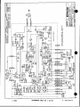
AC-1 OK AC-1 OH
Adapt-A-Com
OPERATING
INSTRUCTIONS
*
~~~~~I
iOF Clear. Comn
Intercom Systems
4065 Hollis St., Emeryville, CA 94608 (510) 496-6666
Q Clear-Com Intercom Systems 810060
1/4/89 REV. B
j -- B---.------l--------0
woX
I rYC~~~~~~ly
£ X
I WJI~~~~~~~l
-~-<-A
~ - -n
- - - -i
, ar
- -- -- -
_s 7
< 8's'-
ts
, .¢
I
|
_
ssn~~~~~~~s
*2SJ
i
W ,~~ _
,o
Cr
I
,
g;1~~~~am
S R~~~~~~~~~~~~~~~
Lu
~~~~~~~~~~~~~~~~~~~~~~~~~~~~~~~~~0
. i E e , 1, XW
Ws
g
. 'i 5701
r
,_Ww
X/Si~~~~~~
~
~~~~
2S
'S
s
sD~~~~~~~~a
~~DIXYMDS DOI-DO -Dys
/
a *Aaa 090018
AC-10 ADAPT-A-COM INSTRUCTION SHEET
DESCRIPTION:
The Clear-Com AC-10 is a versatile, active hybrid device that interfaces the Clear-Com intercom
system with a variety of other communication systems. These include two-wire, three-wire, and
four-wire telephone type systems, carbon systems, and other closed-circuit intercom systems.
The AC-10 s front panel controls include a Mode Select switch, Transmit and Receive level gains,
and A and B Balance controls. An impedance select switch is located on the rear panel.
SET-UP:
1) Connect the Adapt-A-Com to you Clear-Com system via the connector marked Clear-Com on
the rear panel, using standard two-conductor shielded mic cable. The pin assignment on this
3-pin, XLR-type female connector is:
Pin 1: common'
Pin 2: +30 volts DC
Pin 3: intercom audio
2) Select your mode of operation with the Mode Select switch: 2-wire, 3-wire, or 4-wire. The 2wire mode is typically used with telephone-type carbon systems. The impedance select
switch on the rear panel should be set to 'Hi Z" for TELCO type lines and 60052 television
camera systems. It is set to "Low Z" only when used with low impedance television intercom
systems such as the RCA or Daven types.
The 3-wire mode is used with separate transmit and receive lines with a common ground.
This mode "looks" like a carbon headset, and can be used to plug directly into the headset
jack of a carbon system (such as a TV camera).
The 4-wire mode is used when you have a separate transmit pair and a separate receive pair.
NOTE: In the 3-/4-wire mode, the B Balance control is not operative. The impedance select
switch must be set to the "Hi Z" position when the AC-10 is used in the 3-/4-wire mode.
3) Connect the AC-10 to the external communication system via the rear panel binding posts.
2-WIRE: Connect the AC-10 to all two wire systems using only the top two binding posts (the
red ones).
3-WIRE: For 3-wire systems, jump the two black binding posts together for the common
ground. Connect the red binding post marked transmit' to the portion of the circuit that the
AC-10 sends signals on, and the other red binding post (marked "receive') to the portion of
the circuit that the AC-10 is to receive signals from.
4-WIRE: Fora 4-wire system, use alliourbinding posts: a red and blackpairforthetransmit, and a
red and black pair for the receive.
BALANCING THE INTERFACE:
NOTE: Before balancing the system, be sure that the connections to both Clear-Com and the
external communication system have been made. Balance cannot be achieved unless both
systems are connected. Balance is obtained with a built-in test tone via the A and B Balance
switches.
810060 Rev. C 10/90
Page 1
AC-10 ADAPT-A-COM INSTRUCTION SHEET
2-WIRE MODE BALANCING: If your Clear-Com system is supported by an older PS-3000
Power Supply or a CS-200 Main Station, turn the master gain control on he rear panel of the
Main Station fully counter-clockwise. Newer Main Stations and Power Supplies do not have a
master gain.
1) Turn both gain controls on the AC-10 to the 10 o'clock position.
2) Plug a standard Clear-Com headset into the 4-pin XLR-Iype connector marked "Test Headset'
on the AC-10 front panel.
3) While listening on the headset, push the A balance momentary switch and adjust the A
balance trimpol for minimum tone in the headset. Repeat this procedure with the B balance
switch and trimpot. If the unit starts to oscillate or motor-boat, back off both gain controls
slightly and re-balance.
4) Disconnect the test headset.
3-/4-WIRE MODE BALANCING: The procedure is the same as for the 2-wire mode, except the
B balance is inoperative.
ADDITIONAL NOTES:
1) The test tone levels heard in the system are affected by the Transmit and Receive gain control
settings.
2) Attempting to get too much gain from either system can cause instability and oscillation.
3) If you're interfacing to a TELCO line and cannot obtain a satisfactory null on the B balance,
the value of capacitor C-39 should be increased (see schematic). Try adding from .05 uF
to .1 uF across the existing cap.
AC-10K ADAPT-A-COM WITH HOLDING COIL OPTION
The AC-1 OK Adapt-A-Com can interface Clear-Com with standard telephone systems. When
your AC-1 OK has the holding coil option and is connected to a "TELCO" line, the user may dial an
outgoing call from a telephone extension, switch the AC-10K to "Phone Hold", and then hang up
the receiver to keep the party on-line for intercom purposes.
Likewise, an incoming call may be answered by the AC-1 OK that's in the "Hold" condition (instead
of lifting the telephone receiver off the hook). When the phone rings, set the Holding Coil switch
(on AC-1OK front panel) to the "Phone Hold" position. The AC-1OK effectively answers the
phone, connecting the caller to the intercom system. The red LED adjacent to the switch glows
to indicate that the telephone line is seized.
The Clear-Com holding coil circuit provides a simulated termination across the AC-10K to
maintain its stability. This termination is automatically applied when the DC voltage on the
TELCO line input is removed.
For proper operation, the holding coil circuit should be used only on a standard TELCO line "wet"
pair, i.e., a telephone line with a DC voltage across it. For interfaces with non-TELCO "dry" twowire lines, the holding coil is not needed and the internal switch on the holding coil module shold
be set to bypass".
WARNING: To prevent damage to the Holding Coil circuitry; when the AC-10H is used as an
interface to TW (RTS type) systems, the intenal slide switch (S1, on the PCB) MUST be set to
"BYPASS-.
810060Rev.C 10/90
Page2