1
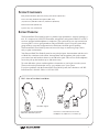
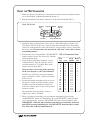
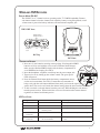
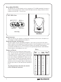
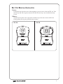
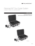
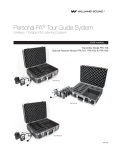
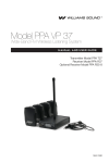
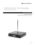
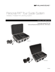
Manual
and
User Guide
Personal PA® Tour Guide System
Wireless, Portable FM Listening System
Transmitter Model PPA T36
Optional Receiver Models PPA R37, PPA R35-8
MAN 158A
PERSONAL PA® FM Tour Guide System,
Models TGS PRO 720, TGS PRO MULTI
Manual & User Guide
Contents
Page
System Components
3
System Overview
3
Safety Information
4
Recycling Instructions
4
Operating Instructions
PPA T36 Transmitter
PPA R37 Receiver
7
PPA R35-8 Receiver
8
Belt Clip Removal/Installation
9
Battery Information
10
Optional Battery Chargers
11
Hints for Using the System
12
In Case Of Difficulty
13
Warranty
14
System Specifications
2
5-6
15-16
System Components
Body Pack Transmitter (PPA T36) with (2) AA batteries (BAT 001)
Noise-cancelling headband microphone (MIC 100)
(10) Receivers (PPA R37 or R35-8) w/batteries (BAT 001)
Instruction manual (MAN 145)
System carry case (CCS 030 S)
System Overview
The Personal PA® Tour Guide System is a portable, high-performance, wireless listening system. It is composed of a PPA T36 Transmitter, microphone, and optional PPA R37 or R35-8
receivers equipped with headphones or earphones. The system allows one-way transmission
of a tour guide’s voice to group members using an FM radio signal. Using the system helps
group members overcome background noise and distance from the person speaking.
The Personal PA® Tour Guide System can be used for large or small tour groups, and in
noisy or quiet environments.
Your Personal PA® Tour Guide System has two principal parts: the transmitter and the receiver. Much like a miniature radio station, the transmitter and microphone pick up the sounds
you want to hear and broadcast them over an FM radio signal. The receivers and headphones
are used to pick up the broadcast up to 100 meters away.
To avoid difficulties, please read through these instructions as you begin to use the system.
Then save them for questions that arise as you continue to use your system.
If you have problems with the Personal PA® Tour Guide System, don’t hesitate to call Williams Sound at 1-800-843-3544 or +1 952 943 2252.
FIG 1: How the Tour Guide System Works
FM Radio Signal
Tour Guide Uses the Body Pack
Transmitter With Microphone
Listeners use Personal Receivers with
Headphones, Earphones, Or Neckloop
3
Safety Information
Hearing Safety:
CAUTION!
The tour guide system is designed to amplify sounds to a high volume level which could
potentially cause hearing damage if used improperly.
To protect your hearing and the hearing of others:
1. Make sure the volume on the receiver is turned down before putting on the earphone or
headphone. Then adjust the volume to a comfortable level.
2. Set the volume level on the receiver at the minimum setting that you need to hear.
3. If you experience feedback with the receiver (a squealing or howling sound), reduce the
volume setting and move away from the T36 transmitter’s microphone.
4. Do not allow children or other unauthorized persons access to the receiver.
Battery Safety and Disposal:
CAUTION!
The transmitter and receiver may be supplied with alkaline batteries. Do not attempt to recharge alkaline batteries, which may explode, release dangerous chemicals, cause burns, or
other serious harm to the user or product.
Pacemaker Safety:
CAUTION!
1. Before using this system with a pacemaker or other medical device, consult your physician or the manufacturer of your pacemaker or other medical device.
2. If you have a pacemaker or other medical device, make sure that you are using this product in accordance with safety guidelines established by your physician or the pacemaker
manufacturer.
Recycling Instructions
Help Williams Sound protect the environment! Please take the time to dispose of your equipment properly.
Product Recycling Instructions:
Please do NOT dispose of your Williams Sound equipment in the household trash. Please
take the equipment to an electronics recycling center; OR, return the product to the factory for
proper disposal.
Battery Recycling Instructions:
Please do NOT dispose of used batteries in the household trash. Please take the batteries to a
retail or community collection point for recycling.
4
Using the T36 Transmitter
1. Make sure there are two alkaline or rechargeable AA batteries in the transmitter. If batteries are not installed, see Battery Information on page 11.
2. Plug the microphone cord into the “Mic Jack” on top of the transmitter (FIG. 2).
FIG 2: T36 Top View
Auxiliary
Input
Power On/Off/Mute
Mic Jack
Channel
Selector
Power On Indicator
3. Optionally, plug in a desired audio source such as a CD or MP3 player using the “Auxiliary Input” jack (WCA 087 stereo auxiliary input cable included). If mic and auxiliary
sources are used together, the audio will be mixed. If only auxiliary source is desired, the
mic can be muted. Do not remove the mic from the “Mic Jack” as the cable is also the
transmitting antenna!
4. Turn the unit on: press and hold the “ON/OFF/MUTE” FIG 3: Channelization Chart
button for three seconds. The “Power On” indicator
should illuminate green.
T36
Freq. R35-8
CH Letter (MHz) CH
5. Select the desired operating frequency. Use the
“Channel Selector” knob to select any of the 16
A
72.1
1
1
B
72.3
2
2
available channels on 72-76 MHz. Refer to the
O
72.6
3
3
channel selection chart, FIG 3.
Make sure the receiver being used is operating
on the same frequency as the T36 transmitter!
NOTE: Up to eight T36’s can operate simultaneously on channels 1-8 (FIG. 3) when used with an
R35-8 receiver.
6. Position the headset microphone boom as close to
the speaker’s mouth as possible without actually
touching. Lapel clip microphones should be attached to a collar or lapel, as close to the speaker’s
mouth as possible.
The transmitter can be placed in a pocket, or
clipped onto a belt or waistband.
4
5
6
7
8
9
10
11
12
13
14
15
16
P
I
R
G
H
C
K
N
D
E
J
S
T
72.8
74.7
75.4
75.7
75.9
72.5
72.2
72.4
72.7
72.9
75.3
75.6
75.8
4
5
6
7
8
-
7. When you pause from speaking, you may mute the microphone by pressing the
“ON/OFF/MUTE” button once momentarily. The “ON/OFF/MUTE” button will flash
red. To unmute the mic, press the “ON/OFF/MUTE” button once momentarily again.
IMPORTANT: When the T36 transmitter is not being used, remember to turn the
unit OFF by pressing and holding the “ON/OFF/MUTE” button for three seconds.
The “Power On” indicator should not be lit.
5
Using the T36 Transmitter, cont.
Gain Control
The gain control can be used to adjust the volume level on both the microphone and auxiliary input.
To adjust the volume level, open the battery door and locate the Gain Control (FIG. 4). Use the supplied plastic screwdriver and rotate to increase “+” or decrease “-” the gain.
FIG 4: T36
Controls
2:1
1:1
- Gain +
- AUX +
Comp
CH Lock
–
AA
+
+
AA
–
j
k
l
m
1. Gain Control
2. Auxiliary Input Level
3. Compression Selector
4. Channel Lock
Auxiliary Input Level
The auxiliary input level can be used to adjust the auxiliary input level only.
To adjust, open the battery door and locate the Auxiliary Input Level (FIG. 4). Use the plastic screwdriver and rotate to increase “+” or decrease “-” the input level.
Note: When using an auxiliary audio source, if the “Aux Input Level” is set too high, there can be
increased audio distortion and decreased battery life.
Note: When using an auxiliary input source, the mic must be plugged in to the “Mic Jack” in
order to transmit audio!
Compression Selector
By default, the T36 compression is set to “Off” for normal operation, or “1:1” compression.
For hearing assistance applications, the compression selector can be set to “On” for “2:1”
compression.
To change this setting, open the battery door and locate the Compression Selector (FIG. 4).
To turn on compression (2:1), slide the “Comp” switch to the position marked “2:1.” To turn
off, slide the “Comp” switch to the position marked “1:1.”
Channel Lock
By default, the T36 channels are unlocked to allow the user to change frequencies as needed.
If desired, channels can be locked to prevent users from changing the channels.
Note: The Channel Lock only locks the electronic frequency; it does not physically lock the
channel selector knob.
To lock or unlock channels, open the battery door and locate the Channel Lock (FIG. 4). To
lock the current channel, slide the “CH Lock” switch to the position marked “ “. To unlock
the channels, slide the “CH Lock” switch to the position marked “ “.
6
On/Off Switch
Volume Control
Wideband FM Receivers
OFF
Earphone
"On" Indicator
Receiver Model PPA R37
Jack
LED
The PPA R37 is a 17-channel receiver operating on the 72-76 MHz bandwidth. Features
seek-button channel selection, channel-lock capability, battery-saving Sleep Mode, on/off
volume control, power/low battery indicator, and stereo/mono earphone jack.
FIG 5: R35 Views
On/Off Switch
Volume Control
OFF
Earphone
Jack
"On" Indicator
LED
R37 Top
R37 Front
Operating the Receiver
1. Insert two (2) AA batteries ensuring correct polarity. If rechargeable NiMH
batteries are to be used with the receiver and a Williams Sound charger,
make sure the Alkaline/NiMH switch inside the battery compartment is
FIG 6
set to NiMH before charging. See FIG 6.
2. Insert the headphone, earphone or neckloop into the stereo output jack.
3. Turn receiver on by turning up the volume control. The green power
LED will turn on.
–
4. Press the Channel Seek button inside the battery compartment once to
+
seek an active transmitter. See FIG 6. If more than one transmitter is
being used, push the seek button additional times until you locate the signal you
want to hear. The receiver will retain the channel setting when the unit is turned off.
5. To lock or unlock a selected channel, turn the power off. While holding the seek button,
turn the power back on. When locked, the receiver will remain on the current channel
regardless of channel seek button presses.
Channel
Seek
AA
+
AA
–
LED Flash Codes
Light Code
Indicates
Description
1 blink
Channel locked
Seek press remains on the current channel
2 blinks
Channel unlocked
Seek press tunes to the next channel present
3 blinks
Channel unlocked; no other
channels present
Seek press attempts to find another channel
On-Off-On-Off...
(continuous)
Batteries are low
Batteries need to be replaced or recharged
Fade-on, Fade-off...
(continuous)
No transmitter is present on
the current channel
Sleep/Power Save mode (extends battery
life)
7
Receiver Model PPA R35-8
The PPA R35-8 is an eight channel receiver, operating on 72-76 MHz bandwidth. It features a
channel selection knob, on/off volume control, LED power and low battery indicator, and an
earphone jack (See FIG. 7). Instructions:
FIG 7: R35-8 Views
Headphone/Earphone
Jack
"On"/Low Battery
Indicator LED
Channel
Selector Knob
On/Off Switch
Volume Control
R35-8 Top
Top
R35-8 Front
R35-8
Front
Battery Installation
Make sure there are two alkaline or rechargeable AA batteries in the receiver. If batteries are
not installed, see Battery Information on page 11.
Connecting Earphones and Headphones
Plug the earphone into the “Headphone/Earphone” jack on the top of the unit. Only monophonic earphones and headphones will operate properly. If stereo headphones are used, sound
will be heard only in one side. Williams Sound evaluates each earphone and headphone
used with the PPA R35-8 receiver; we can only assure optimum performance when Williams
Sound earphones and headphones are used.
FIG. 8
Operating the Receiver
Turn the receiver on by rotating the Volume control
T36
Freq. R35-8
knob. The ON indicator should illuminate RED. Refer
CH Letter (MHz) CH
to the channel selection chart in FIG. 8 to choose from
A
72.1
1
1
8 standard frequencies. Turn the channel selector knob
B
72.3
2
2
to the desired channel. IMPORTANT: Make sure the
O
72.6
3
3
receiver frequency matches the transmitter frequency!
P
72.8
4
4
I
74.7
5
Adjust the volume to a comfortable listening level. To
5
R
75.4
6
6
turn the receiver off, rotate the Volume control knob to
G
75.7
7
7
the left until it clicks off. The ON indicator should not
R35-8
Front
H
75.9
8
8
be lit.
To prolong the battery life of the unit, turn the
receiver off when it is not in use.
8
9
10
11
12
13
14
15
16
C
K
N
D
E
J
S
T
72.5
72.2
72.4
72.7
72.9
75.3
75.6
75.8
-
Belt Clip Removal/Installation
To Install:
Position the belt clip on the rear of the transmitter or receiver unit as shown in FIG. 9A. Turn
the belt clip 180º left or right as shown in FIG. 9B. The belt clip is now installed and ready
for use.
To Remove:
Turn the belt clip 180º so the edge points toward the top of the unit as shown in FIG. 9B.
Gently pull the belt clip away from the unit to remove.
FIG. 9A
FIG. 9B
9
Battery Information
Installation/Removal
Open the battery compartment by lifting the tab on the back of the transmitter or receiver with your
finger. To remove depleted batteries, pull up on the fabric strip.
IMPORTANT: If alkaline (non-rechargeable) batteries are being installed, slide the battery
selection switch in the battery compartment to the “alkaline” position. See FIG. 10 below. If
installing NiMH (or rechargeable) batteries, slide the battery selection switch to the “NiMH”
position.
Press the batteries into place over the fabric strip. Be sure to observe proper polarity (+/-). Damage due
to improper battery installation may void the warranty on the product.
FIG. 10
2:1
1:1
- Gain +
- AUX +
Comp
CH Lock
–
AA
+
+
AA
–
Power LED indicator will flash or turn red when the batteries are getting low (see Low Battery Indicator on chart below). Continue to use equipment until sound becomes weak or distorted, or until the equipment quits operating, then replace or recharge batteries. Do not leave
dead batteries in the transmitter or receivers. The power indicator light may remain on, even
with a battery that is weak. The chart below shows typical battery life with these units:
Model
Battery Type
Battery Life
Low Battery Indicator
PPA T36
Alkaline AA batteries (BAT 001)
30 hours
Power LED flashes
Alkaline AA batteries (BAT 001)
50 hours
Power LED flashes
50 hours
32 hours
Power LED flashes
Rechargeable AA NiMH (BAT 026)
PPA R37
Rechargeable AA NiMH (BAT 026)
PPA R35-8 Alkaline AA batteries (BAT 001)
Rechargeable AA NiMH (BAT 026)
20 hours
32 hours
IMPORTANT WARNINGS:
DO NOT ATTEMPT TO RECHARGE ZINC CARBON (“HEAVY DUTY”),
ALKALINE, OR LITHIUM BATTERIES! DO NOT ATTEMPT TO RECHARGE
SINGLE-USE BATTERIES!
These batteries may heat up and explode, causing possible injury and damage to the
equipment.
Avoid shorting the plus and minus battery terminals together with metal objects.
Battery damage and burns can result! Do not dispose of batteries in fire. Do not
open batteries - toxic chemicals inside.
10
Optional Battery Chargers
Fig: 11A: CHG 3512 / 3512 PRO Multi-Charger
TFP 037
DC Power Connection
Fig: 11B: CHG 3502 Dual-Bay Charger
CHG 3502
Rear View
Receiver or Transmitter
Charging
LED Indicator
TFP 041
DC Power Connection
For more information on available chargers, visit
www.williamssound.com or call +1 952 943 2252.
11
Tips for Using the System
The nominal operating distance between the transmitter and receiver is about 46 meters (150
feet). The operating range will vary in different buildings and surroundings. In some locations,
the signal may momentarily disappear. This is called a “drop-out” and is due to reflection and
cancellation of the radio signal. Moving a few feet should restore the signal.
Keep the transmitter and receiver units at least 1 meter (3 feet) apart. If the transmitter gets
too close to a receiver, it may overload the receiver, causing noisy reception or blocking of the
signal.
Do not use more than one transmitter on the same channel (frequency) at the same time unless
they are physically separated by more than 60 meters (200 feet). Operating more than one
transmitter on the same channel at the same time in the same place will result in interference.
Using Multiple Systems for Multiple Groups:
For multiple tour groups within the same facility, multiple Tour Guide Systems may be operated on the same channel at the same time by maintaining physical separation of more than 60
meters (200 feet) between groups. The physical separation of groups takes advantage of the
FM capture effect which causes receivers to lock onto the closest transmitter.
FIG. 12: Tour Guide Group Separation
12
In Case Of Difficulty
If your Tour Guide System is not working, check the following:
1. Read through the manual and user guide carefully to verify proper setup and installation
of your system.
2. Make sure the batteries are fresh or completely charged and that the “plus” and “minus”
terminals are installed correctly.
3. If the rechargeable batteries work for a short period of time (less than 1 hour) even after
they are fully charged, they must be regenerated. Leave them in the receiver or transmitter with the unit turned on for 5 - 6 hours. Then turn receiver or transmitter off, place it
in the charger, and fully charge the receiver and transmitter (refer to charger instruction
manual). This should restore normal battery life. Rechargeable batteries will gradually
lose their capacity over time and may need to be replaced every 1-2 years.
4. Make sure the microphone is plugged into the T36 Transmitter and the earphone or headphone is plugged into the PPA R37 or R35-8 Receiver.
5. Move the transmitter and receiver closer together. You may be out of range. When using
the system indoors, it’s normal for the signal to momentarily disappear in certain locations. This is called a “drop-out.” Moving a few feet will restore the signal.
6. Do not try to use more than one transmitter on the same channel in close proximity to
each other. MORE THAN ONE TRANSMITTER ON THE SAME CHANNEL WILL
RESULT IN INTERFERENCE IF THEY ARE CLOSE TOGETHER. Keep the transmitters at least 60 meters (200 feet) apart or use separate channels for each system used.
7. If you are still hearing interference on the receivers, turn the transmitter off and listen
with a receiver. If you hear the interference with the transmitter off, you need to change
to a clear channel (see pages 8-9). Call your Williams Sound representative at 1-800-8433544 or +1 952 943 2252 for details.
Notice
Williams Sound assumes no liability for improper use or operation of this equipment. The
user is cautioned to operate the volume controls at the lowest acceptable level, and in a manner that will not cause damage to hearing. Ear pieces and accessories should be worn using
good judgement and for their intended purpose.
Users are cautioned that changes or modifications not expressly approved by Williams Sound
could void the user’s authority to operate the equipment.
13
Limited Warranty
Williams Sound products are engineered, designed, and manufactured under carefully controlled conditions to provide you with many years of reliable service. Williams Sound warrants the Personal PA® Tour Guide System against defects in materials and workmanship for
five (5) years. During the first five years from the purchase date, we will promptly repair or
replace the Personal PA® Tour Guide System. Microphones, earphones, headphones, batteries, cables, carry cases, and all other accessory products carry a 90-day warranty. Chargers
carry a one-year warranty.
WILLIAMS SOUND HAS NO CONTROL OVER THE CONDITIONS UNDER WHICH
THIS PRODUCT IS USED. WILLIAMS SOUND, THEREFORE, DISCLAIMS ALL WARRANTIES NOT SET FORTH ABOVE, BOTH EXPRESS AND IMPLIED, WITH RESPECT
TO THE Personal PA® Tour Guide System, INCLUDING BUT NOT LIMITED
TO, ANY IMPLIED WARRANTY OF MERCHANTABILITY OR FITNESS FOR A PARTICULAR PURPOSE. WILLIAMS SOUND SHALL NOT BE LIABLE TO ANY PERSON OR ENTITY FOR ANY MEDICAL EXPENSES OR ANY DIRECT, INCIDENTAL
OR CONSEQUENTIAL DAMAGES CAUSED BY ANY USE, DEFECT, FAILURE OR
MALFUNCTIONING OF THE PRODUCT, WHETHER A CLAIM FOR SUCH DAMAGES IS BASED UPON WARRANTY, CONTRACT, TORT OR OTHERWISE, THE SOLE
REMEDY FOR ANY DEFECT, FAILURE OR MALFUNCTION OF THE PRODUCTS
REPLACEMENT OF THE PRODUCT. NO PERSON HAS ANY AUTHORITY TO BIND
WILLIAMS SOUND TO ANY REPRESENTATION OR WARRANTY WITH RESPECT
TO THE Personal PA® TOUR GUIDE SYSTEM. UNAUTHORIZED REPAIRS OR
MODIFICATIONS WILL VOID THE WARRANTY.
The exclusions and limitations set out above are not intended to, and should not be construed
so as to contravene mandatory provisions of applicable law. If any part or term of this Disclaimer of Warranty is held to be illegal, unenforceable, or in conflict with applicable law by
a court of competent jurisdiction, the validity of the remaining portions of this Disclaimer of
Warranty shall not be affected, and all rights and obligations shall be construed and enforced
as if this Limited Warranty did not contain the particular part or term held to be invalid.
NOTICE: Williams Sound products are NOT designed for use in extreme temperature,
humidity or chemical environments. The introduction of chemicals such as chlorine, salt
water or human sweat into the product will cause damage to the circuitry. Damage due to
these causes is not covered under the product warranty. If you experience difficulty with your
system, call Toll-Free for customer assistance:
1-800-843-3544 (U.S.A.) or +1 952 943 2252 (Outside the U.S.A.)
If it is necessary to return the system for service, your Customer Service Representative will
give you a Return Authorization Number (RA) and shipping instructions. Pack the system
carefully and send it to:
Williams Sound
Attn: Repair Dept.
10300 Valley View Road
Eden Prairie, MN 55344 USA
Your warranty becomes effective the date you purchase your system. Your returned warranty
card is our way of knowing when your warranty begins. Please take a moment to fill out and
mail the enclosed card. You may also register your product online: www.williamssound.com/
registration.aspx. This information will help us serve you better in the future. Thank you!
14
System Specifications
Transmitter, Model PPA T36
Dimensions:
Weight:
Color:
Battery Type:
Operating Freq’s:
Stability:
Modulation:
RF Output:
Freq Response:
Signal-to-Noise Ratio: Transmit Antenna:
Microphone:
External Controls:
Mic Input:
Aux Input:
Audio Compression:
Compatible Receivers:
Approvals/Directives:
Warranty:
Note:
Receiver, Model PPA R37
Dimensions:
Weight:
Color:
Battery Type:
Current Consumption:
Operating Freq.:
FM Deviation:
De-Emphasis:
LED Indicator:
Sensitivity:
Input Overload:
Frequency Response:
Signal-to-Noise Ratio:
Receive Antenna:
Audio Output:
Output Connector:
Approvals:
Warranty:
4.1” L x 2.8” W x 1.1” T (104 mm x 71 mm x 28 mm)
2.9 oz (82 g), no batteries
Black, shatter-resistant PC/ABS plastic
Two (2) AA 1.5 V non-rechargeable Alkaline batteries (BAT 001), 70 mA nominal current
drain, 30 hours approx. life or
Two (2) AA 1.5 V NiMH rechargeable batteries (BAT 026), 70 mA nominal current drain, 20
hours per charge approx., recharges in 14–16 hours, uses CHG 3502 or CHG 3512 Charger
Selectable, 16 channels, 72.1 – 75.9 MHz* (channels 1-8 correspond with R35-8 receiver channels)
± .005%, frequency synthesized, crystal reference, PLL
Wide-band FM, 75 kHz pk, 75 µS pre-emphasis
80 mV/m at 3 m (max. allowed by FCC rules)
200 Hz to 13 kHz, ± 3 dB at 1% max. THD
65 dB (typical) transmitted
Integral with microphone cord
Electret type, 3.5 mm mono phone plug
Momentary push button: push and hold 3 seconds for power On/Off, push and release for
microphone mute On/Off; Rotary sixteen channel switch (with internal channel lock switch)
3.5 mm mono phone jack with electret mic bias, internal adjustable gain with 25 dB range
2.5 mm stereo phone jack, internal adjustable gain with 60 dB range
1:1 or 2:1 ratio selected with internal slide switch
PFM R31, PFM R32, PFM R33, PFM R36, PPA R37, PPA R35-8, PPA R1600
FCC, Industrie Canada, RoHS, WEEE
5 years, parts and labor (90 days on accessories)
FCC regulations, section 15.21, requires the user to comply with the rules of transmitter operation. Any changes or modifications made by the user not expressly approved for compliance
may result in the loss of all privileges and authority to operate the equipment
4.1” L x 2.8” W x 1.1” T (104mm x 72mm x 28mm)
4 .6 oz (130 g) with batteries, 2.6 oz w/o batteries (73g)
Black
Two (2) AA non-rechargeable alkaline batteries (BAT 001), approx. 50 hours battery life or
Two (2) AA rechargeable NiMH batteries (BAT 026), 1500 mAh, approx 32 hours battery life
Nominal 52 mA
17 channels: 72.1, 72.2, 72.3, 72.4, 72.5, 72.6, 72.7, 72.8, 72.9, 74.7, 75.3, 75.4, 75.5, 75.6,
75.7, 75.8 or 75.9 MHz*
± 75 kHz
75 µS
Power on: Bright Green. Low Battery: Flashes.
2 µV at 12 dB Sinad with squelch defeated
100 mV
200 Hz to 15 kHz, ± 3 dB
65 dB at 100 µV
Integral with earphone/headphone cord
35 mW, max. 16 Ω load
3.5 mm stereo phone jack, accepts either stereo or mono plug
FCC, Industrie Canada, RoHS, WEEE
Five years, parts and labor. 90 days on cords, earphones,
headphones, batteries and other accessories
*DISCLAIMER: FCC RULES LIMIT USE OF THIS EQUIPMENT TO “AUDITORY ASSISTANCE FOR THE HANDICAPPED.”
This device complies to “RSS-Gen Issue 2 June 2007” for Industrie Canada and FCC part 15.105(b) for the United States.
Operation is subject to the following two conditions: (1) this device may not cause interference, and (2) this device must accept
any interference, including interference that may cause undesired operation of the device.
This device complies with ICES-003 class B. Test data is available from the manufacturer on request.
Note: Specifications subject to change without notice.
15
Receiver, Model PPA R35-8
Dimensions:
Weight:
Color:
Battery Type:
Current Consumption:
Operating Freq:
Intermediate Freq:
FM Deviation:
De-emphasis:
LED Indicator:
Sensitivity:
Input Overload:
Frequency Response:
Signal to Noise ratio:
Receive Antenna:
Audio Output:
Output Connector:
Squelch:
Notes:
Approvals:
Warranty:
4.5” H x 2.8 W x 1.1” T (115 mm x 71 mm x 28 mm)
4.6 oz (130 g) w/ batteries
Black
Two (2) AA non-rechargeable alkaline batteries (BAT 001), approx. 50 hrs. battery life; or
Two (2) AA rechargeable NiMH batteries (BAT 026), 1500 mAh, approx. 32 hrs. battery life
Nominal 40 mA
8 channels: 72.1, 72.3, 72.6, 72.8, 74.7, 75.4, 75.7, or 75.9 MHz*.
10.7 MHz
+/- 75 kHz
75 uS
Power: Red. Low Battery: Flashes
2 µV at 12 dB SINAD with squelch defeated
20 mV
40 Hz to 15 kHz +/- 3 dB
60 dB at 100 µV
Integral with earphone/headphone cord
35 mW, max 16 ohm load
3.5 mm mono phone jack
Located inside battery door. Factory set for 25 dB S/N. Squelch
may be set with JFD-7104-5 from Sprague Goodman or any flat tipped tuning tool with tip size .095 X .016
The R35-8 is NOT field tunable. The eight channels have been
carefully selected to inhibit inter-modulation interference. Channel frequencies are 72.1, 72.3, 72.6, 72.8, 74.7, 75.4, 75.7, and 75.9 MHz.
FCC, Industrie Canada, RoHS, WEEE
Five Years, Parts and Labor. 90 days on cords, earphones, headphones, batteries, and other accessories
*DISCLAIMER: FCC RULES LIMIT USE OF THIS EQUIPMENT TO AUDITORY ASSISTANCE.
Note: Specifications subject to change without notice.
©2011 Williams Sound, LLC
MAN 158A