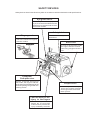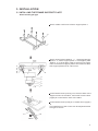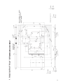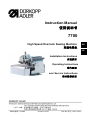
1
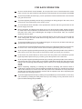
Instruction Manual
使用说明书
7700
High Speed Overlock Sewing Machine
高速包缝机
GB
CN
Installation Instructions
安装须知
Operating Instructions
操作须知
Basic Service Instructions
基本维修须知
Edition/版本:07/2006
Printed in China
Part.-No./件号:0791 770741
7700 - Basic Machines
7700 - 基本机型
7704-O42-M00P
Light and medium material 3-thread 1-needle standard overlock machine
薄至中厚料 3 线单针标准型包逢机
7714-B43-M00P
Light and medium material 4-thread 2-needle standard overlock machine
薄至中厚料 4 线双针标准型包逢机
7716-C42-M00P
Light and medium material 5-thread 2-needle safety seam machine
薄至中厚料 5 线双针标准型安全缝包逢机
Instruction Manual
使用说明书
Contents
目录
Installation Instructions
安装须知
Operating Instructions
操作须知
Basic Service Instructions
基本维修须知
Foreword
This instruction manual is intended to help the user to become familiar
with the machine and take advantage of its application possibilities in
accordance with the recommendations.
The instruction manual contains important information on how tooperate
the machine securely, properly and e'conomically.Observationof the
instructions eliminates danger, reduces costs for repair anddown- times,
and increases the reliability and life of the machine.
The instruction manual is intended to complement existing national
accident prevention and environment protection regulations.
The instruction manual must always be available at the
machine/sewing unit.
The instrction manual must be read and applied by any person that is
authorized to work on the machine/sawing unit. This means:
Operation, including equipping, troubleshooting during the workcycle,
removing of fabric waste,
Service (maintenance, inspection, repair and/or
Transport.
The user also hai to assure that only authorized person network onthe
machine.
The user is obliged to check the machine at least once per shift forapparent
damages and to immediatly report any changes (includingthe performance
in service), which impair the safety.
The user company must ensure that the machine is only operated inperfect
working order.
Never remove or disable any safety devices.
If safety devices need to be removed for equipping, repairing or maintaining,
the safety devices must be remounted diredtly after completion of the
maintenance and repair work.
Unauthorized modificationof the machine rules out liability of the manufacturer
for damage resulting from this.
Observe all safety and danger recommendations on the machine/unit!
the yellow-and-black striped surfaces designate permanend dangerareas,
egdanger of squashing,cutting,shearing or collision.
Besides the recommendations in this instruction manual also observe
the general safety and accident prevention regulations!
General safety instructions
The non-observance of the following safety instructions can cause bodily
injuries of damages to the machine.
1. The machine must only be ommissioned in full knowledge of the instruction
book and operated by persons with appropriate training.
2. Before putting into service also read the safety rules and Instructions
of the motor supplier.
3. The machine must be used only for the purpose intended. use of the
machine without the safety devices is not permitted. ubserve all the
relevant safety regulations.
4. When gauge parts are exchanged (e.g. needle, presser foot, needle
plate,feed dog and bobbin)when threading,when the workplace is left,
and during service work, the machine must be disconnected from the
mains by switching off the master switch ordisconnecting the mains
plug.
5. Daily servicing work must be carried out only by appropriately trained
persons.
6. Repairs, conversion and special maintenance work must only be carried
out by technicians or persons with appropriate training.
7. For service or repair work on pneumatic systems, disconnect the machine
from the compressed air supply system ( max. 7-10 bar).Before disconnecting,
reduce the pressure of the maintenance unit. Exceptions to this are only
adjustments and functions checks made by appropriately trained technicians.
8. Work on the electrical equipment must be carried out only by electricians
or appropriately trained persons.
9. Work on parts and systems under electric current is not permitted , except
as specified in regulations DIN VDE 0105.
10. Conversion or changes to the machine must be authorized by us and made
only in adherence to all safety regulations.
11. For repairs, only replacement parts approved by us must be used.
12. Commissioning of the sewing head is prohibited until such tim e as the
entire sewing unit is found to comply with EC directives.
It is absolutely necessary to respect
the safety instructions marked by these signs.
Danger of bodily injuries!
Please note also the general safety instructions.
!
FOR SAFE OPERATION
So as to avoid electric shock hazards, do not open the cover of the electrical box of the
motor or touch any part inside the electrical box with the power to the machine turned ON.
To prevent possible personal injury, never operate the machine with the belt cover and the
eye guard removed.
To protect against possible personal injury resulting from being caught in the motor, use a
motor that is provided with a motor pulley cover.
To avoid electric shock hazards, never operate the machine with the ground wire for the
power supply removed.
During operation, be careful not to allow your or any other person's head, hands or fingers
to come close to the handwheel, V belt and motor so as to prevent possible personal injury
that may occur when your hands/fingers are caught in the machine. Also, do not place
anything close to them.
So as to avoid possible injury to your hands and fingers, do not put any of them near the
cloth cutting knife and the needle when turning the power to the machine or while the
machine is in operation.
To prevent possible injury to your hands and fingers, do not put any of them inside the eye
guard while the machine is in operation.
To avoid electric shock hazards and accidents arising from damaged electrical components,
be sure to turn OFF the power switch before inserting/detaching the power plug.
So as to protect against possible personal injury resulting from abrupt start of the machine,
make sure to turn OFF the power to the machine when you leave your machine.
In the event of a power failure, be sure to turn OFF the power to the machine to protect
against possible personal injury resulting from abrupt start of the machine.
So as to protect against possible personal injury resulting from abrupt start of the machine,
remove the belt cover, motor pulley cover and the V belt after turning OFF the power to the
machine and confirming that the sewing machine will not run even by depressing the start
Before inspecting, adjusting or cleaning the machine, threading the machine head or
replacing the needle, so as to protect against possible personal injury resulting from abrupt
start of the machine, be sure to turn OFF the power to the machine so as to prevent an
accident and confirm that the sewing machine will not operate even when depressing the
foot pedal of the sewing machine.
To protect against personal injury resitting from possible drop of the machine, do not carry
your machine by holding the cloth plate cover by hand. Doing so may cause the cover to
open or break resulting in drop hazards.
SAFETY DEVICES
Safety devices herein described may differ in accordance with the destination and specifications.
Eye guard cover
A cover to prevent the injury to the
eyes, the head or the like due to the
dispersion of components such as
the broken needle.
Safety label
Finger guard
A cover to prevent the injury
due to the contact of fingers
with the needle .
Cautions on safety are
described.
Belt cover
A cover to prevent the hands,
the fingers and the clothes
from being caught with the V
belt.
Cloth plate,
Cloth plate cover
Covers to prevent the injury to
the hands, the fingers and hair
of the head,and the damage to the
clothes by being caught with the
rotating shafts.
Caution label for the
Injury to the fingers
Do not allow your hands,
fingers, etc. to come close
to the knife to prevent the
injury caused by the knife.
Looper cover
A cover to prevent the injury
due to the contact of hands
and fingers with the thread
take-up lever.
CONTENTS
1.
DESERIPTION OF PROPER USE............................................................................. 1
1
2.
SPECIFICATIONS...................................................................................................2
2
3.
INSTALLATION....................................................................................................... 3
3.1 INSTALLING THE FRAME SUPPORT PLATE.............................................................3
3.2 ATTACHING THE BELT COVER................................................................................5
3.3 INSTALLING THE PEDALS.......................................................................................5
3
3
5
5
4.
PREPARATION AND OPERATION.......................................................................... 6
4.1 LUBRICATION.........................................................................................................6
4.2 CHECKING THE DIRECTION OF ROTATION...............................................................7
4.3 ATTACHING NEEDLES..............................................................................................7
4.4 THREADING THE MACHINE......................................................................................8
.4.5 ADJUSTING THE PRESSURE OF THE PRESSER FOOT
AND REMOVING THE PRESSER FOOT.....................................................................9
4.6 ADJUSTING THE STITCH LENGTH...........................................................................9
4.7 ADJUSTING THE DIFFERENTIAL FEED....................................................................9
6
6
7
7
8
.
9
9
9
5.
BASIC SERVICE INSTRUCTIONS...........................................................................
10
5.1 ADJUSTING THE KNIVES AND OVEREDGE WIDTH..................................................
10
5.2 CLEANING THE MACHINE HEAD............................................................................
10
5.3 CLEANING THE FILTER AND PUMP NET...............................................................
11
5.4 MOTOR PULLEY AND V BELT...............................................................................
11
5.5 DIMENSIONS USED TO ADJUST THE LOOPER AND THE NEEDLE GUARD................
12
5.6 DIMENSIONS RELATED TO THE POSITION OF THE THREAD TAKE-UP
AND THE LOOPER THREAD CAM(STANDARD ADJUSTMENT).................................
14
5.7 CONVERSION TABLE OF THE NEEDLE NUMBER.................................................
15
10
10
10
11
11
12
6.
TABLE CUTOUT SEMI SUBMERGED ASSEMBLY....................................................
16
16
7.
TABLE CUTOUT FULLY SUBMERGED ASSEMBLY..................................................
17
17
14
15
1. DESERIPTION OF PROPER USE
The sewing unit 7700 is designed for the sewing of light weight
material which generally consists of textile fibres or leather.
These material are commonly used in the garment and furnishing
industries.furthermore the 7700 may also be employed to perform
seams in so called technical textiles.
As these applications are relatively rare and extremely varied the
user is advised to evaluate any possible danger arising from such
applications DURKOPP ADLER AG will be pleased to assist.
..
Depending on the result of this evaluation suitable safety measures
have to be taken.
In general the 7700 may only be used for dry material.
The material thickness must not exceed 6mm when compressed by
the sewing foot.
The material must not contain any hard objects as otherwise the
7700 must be operated with anneedle breakage protection shield.
Such needle breakage protection shield is not available at this
time.
Usable threads are spun threads or bulk threads made of textile
fibres with dimensions up to NM30/3.
Prior to the use of other threads any possible dangers arising there
from have to be evaluated andappropriate safety measures must be
taken if necessary.
The 7700 must only be installed and operated in a dry and clean
environment.
Any use in other environments may necessitate furthera measures
to be agreed upon.(see EN60204-3-1; 1990)
..
DURKOPP ADLER AG as a manufacturer of industrial sewing
machines assume that all personnel operating our products are
atleast semi - skilled and all operations and,where applicable their
dangers are presumed to be known.
1
2. SPECIFICATIONS
2
3. INSTALLATION
3.1 INTALLING THE FRAME SUPPORT PLATE
Semi-submerged type
Attach rubber cushion 2 to frame support plate 1
2
1
Attach support plate washer 3 , support plate bolt
spacer 4 , frame support plate 1 and support plate
washer 3 in the written order to the machine table
Then fix the frame support plate to the machine table
with support plate bolt A 5 and nut 6 .
3
4
3
6
5
1
5
3
4
1
3
6
5
Install waste chute opening 7 on the front side of the
Upper surface of the table , and install waste chute
(upper) 8 on the bottom face of the table.
7
Install waste chute (lower) 9 on waste chute (upper)
8.
The installation of the chutes can be adjusted within
a length of 48 mm.
9
8
48mm
3
Fully-submerged type
Attach frame support plate joint A 4 , frame
support plate joint B 3 and rubber cushion 2
to frame support plate 1 .
4
2
1
3
Fix support plate bolt B 6 to the machine table
Put frame support plate joint A 4 and frame
support plate joint B 3 between support plate
washers 5 respectively.
4
5
Install frame support plate 1 so that the cloth
plate is 5 mm higher than the upper surface of
the machine table.
1
5
5
5
6
3
6
5
5
6
Install waste chute stopper plate 9 on frame
support plate 1 .
Install waste chute (upper) 7 on waste chute
stopper plate 9 .
Install waste chute (lower) 8 on waste chute
(upper) 7.
The installation of the chutes can be adjusted
within a length of 48 mm.
9
1
7
8
48
m
m
4
3.2 ATTACHING THE BELT COVER
Caution: Danger of injury!
To protect against possible person injury due to abrupt start of the machine, be sure to start the
following work after turning the power off and ascertaining that the motor is at rest.
Attach belt cover 1 to the machine head.
3.3 INSTALLING THE PEDALS
Caution: Danger of injury!
To protect against possible person injury due to abrupt start of the machine, be sure to start the
following work after turning the power off and ascertaining that the motor is at rest.
Install starting pedal 1 on the left and presser lifter
pedal 2 on the right as seen from the operator.
1
2
4
Use an S-shaped hook 3 to connect chain 5 of the
presser lifter pedal to the hole located in the top
end of presser lifting lever 4.
5
3
5
4. PREPARATION AND OPERATION
To avoid malfunction and damage of the machine, confirm the following:
Before you put the machine into operation for the first time after set-up, clean it thoroughly.
Remove all dust gathering during transportation and oil it well.
Confirm that the voiltage has been correctly set.
Confirm that the power plug has been properly connected to the power supply.
Never use the machine in the state where the voitage type is different from the designated one.
4.1 LUBRICATION
Caution: Danger of injury!
To protect against possible person injury due to abrupt start of the machine, be sure to start the
following work after turning the power off and ascertaining that the motor is at rest.
1
2
Remove oil cap 1 .
Pour DA32 Oil(Order No.9047 000032) into the
oil reservoir.
Supply oil until the oil surface reaches between
the two red marke r lines when oil gauge 2 is
observed from the side.
(Caution)
Be careful not to supply oil above the upper red
marker line, or else troubles due to excessive
lubrication may result.
Change oil when one month has passed after
the set-up of the sewing machine. Then,
change oil every six months.
Supply oil if the oil surface comes down under
the lower marker line when observing the oil
gauge from the side.
(Caution)
Apply two or three drops of oil to the needle bar
and upper looper guide portion when operating
the machine for the first time after set-up or after
or after a long period of disuse.
6
4.2 CHECKING THE DIRECTION OF ROTATION
The correct direction of rotation of the sewing machine
is clockwise when observing the machine from the
handwheel side.
Never allow the machine to rotate in reverse direction.
If the machine rotates counter clockwise, the oil pump
will fail to function resulting in seizure.
4.3 ATTACHING NEEDLES
Caution: Danger of injury!
To protect against possible person injury due to abrupt start of the machine, be sure to start the
following work after turning the power off and ascertaining that the motor is at rest.
The standard needle is DC27 # 11/B27 Nm 75 (Order.
No.9092 002700 075S). You can also use he DC x 1
needle. In this case, however, the clearance provided
between the needle and the looper may be required
to be adjusted. If sewing needs to be carried with a finely
adjuste d thread tension, use the DC x 27 needle.
2
Bring needle clamp 1 up to the highest position.
Loosen needle screw 2 , and fully insert the
needle into the needle clamp hole with the needle
recess facing backward as viewed from the
operator's side.
Tighten needle screw 2 .
1
2
2
2
1
22
2
1
7
4.4 THREADING THE MACHINE
Caution: Danger of injury!
To protect against possible person injury due to abrupt start of the machine, be sure to start the
following work after turning the power off and ascertaining that the motor is at rest.
Thread the machine as shown in the figure. (Threading diagram is pasted inside the looper cover.)
1
2
2
Caution) Raise looper thread cam thread guide 1
and perform threading. Return looper
thread cam thread guide 1 to its home
position and securely fix it to thread
guide spring 2 .
(Caution) Be sure to pass the needle thread for
for double chainstich through the needle
thread take-up lever.
(Pass the needle thread for overlocking
through the thread take-up lever located
outside.)
(Caution) When using an untwisted thread
such as wooly nylon thread or weak
Intermediate
thread, donot wind it round the
thread guide
intermediate thread guide.
8
4.5 ADJUSTING THE PRESSURE OF THE PRESSER FOOT AND EMOVING
THE PRESSER FOOT
Caution: Danger of injury!
To protect against possible person injury due to abrupt start of the machine, be sure to start the
following work after turning the power off and ascertaining that the motor is at rest.
Increase
Decrease
1
Adjust the pressure of the presser foot by turning
presser foot adjust screw 1.
When the adjust screw is turned clockwise, the
pressure will increase . When it is turned
counterclockwise, the pressure will decrease.
To open presser foot 2 sideward, raise the needle
to the highest position of its stroke and lower
presser bar lifting lever 3 .
Lower
3
2
4.6 ADJUSTING THE STITCH LENGTH
Caution: Danger of injury!
To protect against possible person injury due to abrupt start of the machine, be sure to start the
following work after turning the power off and ascertaining that the motor is at rest.
1
Slowly turn the handwheel as you keep depressing
pushbutton 1 , and you will find a point at which
the pushbutton goes in farther.
With the above condition maintained, align the
desired scale mark on the handwheel with mark 2
on the belt cover. Use the scale mark as reference
Reset pushbutton 1 after setting the scale mark.
2
Depress
4.7 ADJUSTING THE DIFFERENTIAL FEED
Caution: Danger of injury!
To protect against possible person injury due to abrupt start of the machine, be sure to start the
following work after turning the power off and ascertaining that the motor is at rest.
3
Stretching
stitch
Gathening
stitch
2
Loosen differential feed lock nut 2 . Move
differential feed adjusting lever 1 up for
stretching stitch or down for g a t h e r ing stitch.
When you want to move differential feed
adjusting lever 1 only slightly, use differential
feed fine adjustment screw 3 .
when the scale mark is set to -1 , the machine
will perform stretching stitch with a differential
feed ratio of 1 : 0.8, and when it is set to 0 , the
differential feed ratio betweenthe main feed dog
and the differential feed dog will be 1 : 1 .
The maximum differential feed ratio for
gathering is 1 : 1.9 ( it can be set to 1 : 2.9
depending on the adjustment of the internal
mechanism of the sewing machine). The scale
marks beyond 0 are used as reference.
1
9
“
5. BASIC SERVICE INSTRUCTIONS
5.1 ADJUSTING THE KNIVES AND OVEREDGE WIDTH
Caution: Danger of injury!
To protect against possible person injury due to abrupt start of the machine, be sure to start the
following work after turning the power off and ascertaining that the motor is at rest.
Height of the lower knife
Loosen setscrew 2 and adjust the height of lower
knife 1 so that its edge is flush with the throat
plate surface.
6
4
3
Height of the upper knife
Loosen setscrew 4 and perform adjustment so
that upper knife 3 overlaps lower knife 1 by 0.5 to
1 mm when upper knife 3 is at its lowest position.
Overedge width
Overedge widths of 1.6 through 6.4 mm are
provided by changing the parts or by using
subclass models. (The overedge width will be
slightly larger than the knife cut width.)
5
2
To change the overedge width :
Loosening setscrew 5 , push lower knife 1 to the
left and fix it.
Loosen setscrew 6 and move upper knife 3 as
required, then fix it.
Lower the upper knife to its lowest point and
loosen setscrew 5 . Tighten setscrew 5 when the
lower knife comes in xontact with the upper knife.
1
(Caution)
Be sure to tighten setscrew 5 before operating
machine.
After the completion of adjustment, make the
knives cut a thread to make sure of sharpness of
the knives.
Resharpening the lower knife
When the lower knife has become dull ,
resharpen it as shown in the figure left.
5.2 CLEANING THE MACHINE HEAD
Caution: Danger of injury!
To protect against possible person injury due to abrupt start of the machine, be sure to start the
following work after turning the power off and ascertaining that the motor is at rest.
Clear lint from inside the looper cover and the needle bar and components about one or twice a day. If not,
oil may leak or the sewing material will be soiled.
(caution) Do not wipe the coated surface of the machine head with lacquer thinner. Doing so will damage
the coated surface.
10
5.3 CLEANING THE FILTER AND PUMP NET
2
-To use the sewing machine for an extended period of
time, clean filter 1 and pump net 2periodically twice
or three times a year. If the filter and pump net are
clogged with dusts, the machine components may be
seized or womout extraordinarily. So,carefully check
the filter and pump net.
-If the lubricating oil in the machine is stained, change
the oil also at the time of cleaning.
1
5.4 MOTOR PULLEY AND V BELT
Use a clutch motor of 1/2 HP (400W).
Use an M type or a DIN 2215 standard V belt.
Relations among number of revolutions of sewing machine, motor pulley, and length of V belt are as
shown in the aforementioned table.
Effective diameter of the handwheel of sewing machine head is 50.6 mm.
11
5.5 DIMENSIONS USED TO ADJUST THE LOOPER AND THE NEEDLE
Caution: Danger of injury!
To protect against possible personal injury due to abrupt start of the machine, be sure to start the
following work after turning the power off and ascertaining that the motor is at rest.
To avoid possible accidents due to unfamiliarity with the machine, get a maintenance man who
has a good knowledge of the machine or serviceman of our distributor to adjust the machine or
replace any of its parts.
To avoid possible personal injury when the machine starts, it has to be ascertained in prior to the
actuationof the machine that no screws are loosened and no components come in contact with
one another.
(Caution) The dimensions given in the table are standard ones to be used to adjust the looper.
They are intended to be used for reference and should be changed more or less in
accordance with the sewing products and thread to be used.
E
F
A
G
D
7704
7705
E
B
A
D
7714
A
C
7716
A
C
B
7743
A
B
C
D
E
F
G
7704
11
11.8
4.8
4
7705
11
11.8
4.8
4
7714
11
11.8
4.8
4
7716
11
11.8
4.8
4
7714-O42-M09P
11
10.5
4.9
4
D53
7716- D73 -X00P
12.6
11.1
12.8
4.9
3
1.8
7743
11
9.5
11.8
4.8
4
1.8
10.1
9.5
10.1
1.8
12
clearance provided between
needle and blade point of
lower looper
1
Push need to this side
Adjust the lower looper so that the needle is pushed
by 0.05 to 0.1 mm to this side by the blade point of
lower lopper in the state where the blade point of lower
looper is aligned with the center of needle.
Then, adjust traveling needle guard 1 so that the
clearance provided between the needle and the
blade point of lower looper should be 0 to0.05 mm
in the state where the needle is pushed to this side
by traveling needle guard 1 .
For the 2-needle over lock machine , adjust both the
Ieft and right needles in the same manner.
Needle guard components
7704/7705/7714
7716
13
5.6 DIMENSIONS RELATED TO THE POSITION OF THE THREAD TAKE-UP AND
THE LOOPER THREAD CAM (STANDARD ADJUSTMENT)
Caution: Danger of injury!
To protect against possible person injury due to abrupt start of the machine, be sure to start the
following work after turning the power off and ascertaining that the motor is at rest.
Position of the needle thread take-up lever and the needle thread guide
7704/7705
7714
7716
7743
Position at which the lower end of
thread hole of the needle thread
guide is aligned with the edge line
of the needle thread take-up lever.
(Caution) The needle thread take-up lever shall be
positioned at the lower dead point.
7704-O42-M 09P
(Caution) The needle thread take-up lever shall be
positioned at the lower dead point.
14
Position of the looper thread take-up lever and the looper thread guide
J
B
K
A
F
I
A
C
B
C
D
E
F
G
G
K
26 22 12
6
I
27 23.5
9
E
J
H
68 25 44.5 22 37 26 9
8
D
26 22
24 8 26 19 15 18.5
30 26.5 12
26
H
6
10
8 27 23.5
For -042-M09P only
B
J
L
K
O
A
E
A
M
7704-O42-M09P
B
C
D
68.5 24
E
F
G
43
H
I
J
K
L
M N
O
10 17 6.8 20 23.5 35
N
Dimensions of E and G are adjustmaent values when the
upper looper is at rightmost point.
Adjustment value for the looper thread cam (7716)
Thread
Make sure that the looper thread cam releases the looper thread when the needle tip is positioned
_
+0.5
mm against the bottom face of the throat plate
5.7 CONVERSION TABLE OF THE NEEDLE NUMBER
15
6. TABLE CUTOUT SEMI SUBMERGE D ASSEMBLY
16
7 .TABLE CUTOUT FULLY SUBMERGE D ASSEMBLY
17