1
CASIO Interactive Whiteboard
E
YA-W72M/YA-W82M
User’s Guide
z Be sure to read the “Safety Precautions” and “Operating Precautions” in the “Read this first!”
document that comes with the CASIO Interactive Whiteboard, and make sure you use this product
correctly.
z Keep this manual in a safe place for future reference.
z Visit the site below for the latest version of this manual.
http://world.casio.com/manual/projector/
1
Contents
Introduction ..................................................................................................... 6
What is an Interactive Whiteboard?........................................................................... 6
About this manual....................................................................................................... 8
Chapter 1: Getting Ready ............................................................................... 9
Preparing the Digital Pen ......................................................................................... 10
To load a battery into the digital pen ................................................................... 10
Turning the Digital Pen On or Off ..................................................................................... 10
Replacing the Pen Nib ......................................................................................... 11
To replace the pen nib .................................................................................................... 11
Replacement Ballpoint Pen Refills and Stylus Refills ........................................................ 11
Establishing a Connection between the Digital Pen and Computer (Pairing)...... 12
To connect a Bluetooth adapter to your computer .......................................................... 13
To pair the digital pen with your computer....................................................................... 14
Digital Pen Operation Indicator............................................................................ 16
Installing the Software.............................................................................................. 17
Minimum Computer System Requirements......................................................... 17
Minimum Computer System Precautions ........................................................................ 18
To install the software ..................................................................................................... 18
To start up the setup launcher......................................................................................... 19
To install the DSPD ......................................................................................................... 20
To install Interactive Whiteboard for CASIO ..................................................................... 20
To install Dot Pattern Printer for CASIO ........................................................................... 21
To install .NET Framework............................................................................................... 22
Checking for Proper Installation ....................................................................................... 22
Setting Up the Dot Screen, Projector, and Computer ............................................ 23
Dot Screen Part Names ....................................................................................... 23
Setting Up the Dot Screen for Projection ............................................................ 23
To set up the dot screen for projection............................................................................ 23
Projecting a Computer Screen Image onto the Dot Screen ................................ 25
Chapter 2: Using Interactive Whiteboard for CASIO.................................. 26
Interactive Whiteboard for CASIO Overview ........................................................... 26
Interactive Whiteboard for CASIO Modes ........................................................... 26
Registering Your Product (Serial Key Input) ........................................................ 27
To input the serial key...................................................................................................... 27
Calibration............................................................................................................ 27
To perform calibration ..................................................................................................... 28
To re-perform calibration ................................................................................................. 29
Performing Calibration after Each Startup........................................................................ 29
Basic Operations ................................................................................................. 30
To start up Interactive Whiteboard for CASIO .................................................................. 30
To exit Interactive Whiteboard for CASIO......................................................................... 30
Using the Main Toolbox................................................................................................... 31
To view version information ............................................................................................. 32
Mouse Control Mode Digital Pen Operations................................................................... 32
Using the PowerPoint Control Mode ....................................................................... 33
PowerPoint Control Mode Operational Flow ....................................................... 33
2
Conducting a Slideshow in the PowerPoint Control Mode ................................. 34
To start a slideshow in the PowerPoint Control Mode ..................................................... 34
To end a slideshow in the PowerPoint Control Mode ...................................................... 35
Digital Pen Operations during a Slideshow (Power Point Control Mode) .......................... 35
Changing the Margin Settings ............................................................................. 38
To configure display settings ........................................................................................... 38
To configure paper settings............................................................................................. 39
To configure advanced paper settings............................................................................. 40
Using the Presentation Mode .................................................................................. 41
Presentation Mode Operational Flow .................................................................. 41
Conducting a Slideshow in the Presentation Mode ............................................ 42
To start a slideshow in the Presentation Mode ................................................................ 42
To select full-screen view or window view for a slideshow ............................................... 43
To end a slideshow in the Presentation Mode ................................................................. 43
Digital Pen Operations during a Slideshow (Presentation Mode) ...................................... 43
Changing Presentation Mode Configuration Settings ......................................... 47
To configure Presentation Mode configuration settings ................................................... 47
Changing Presentation Mode Startup Default Settings....................................... 48
To edit the Presentation Mode startup default setup file .................................................. 48
Using the Capture & Draw Mode ............................................................................. 51
Capture & Draw Mode Operational Flow ............................................................. 51
Capturing and Drawing on the Currently Displayed Computer Screen Image .... 52
To capture and draw on the currently displayed computer screen image ........................ 52
To capture and draw on another image........................................................................... 54
To display previously captured images ............................................................................ 55
To exit the Capture & Draw Mode ................................................................................... 55
To open and edit a saved DST file ................................................................................... 56
Digital Pen Operations in the Capture & Draw Mode ....................................................... 56
Changing Capture & Draw Mode Startup Default Settings ................................. 58
To edit the Capture & Draw Mode startup default setup file............................................. 58
Tool Operations in the Presentation Mode and Capture & Draw Mode ................ 61
Write/Draw Tool Operations ................................................................................ 61
To write on a page with a Pen or Marker Pen .................................................................. 61
To draw a circle, triangle or rectangle on a page (Presentation Mode) ............................. 61
To draw a straight line or arrow on a page (Presentation Mode) ...................................... 62
To paste an image file into a page (Presentation Mode)................................................... 63
To select a single object .................................................................................................. 63
To select multiple objects ................................................................................................ 64
To specify the type and thickness of an object line .......................................................... 64
To specify the color of an object...................................................................................... 65
To move or to resize objects ........................................................................................... 65
To rotate objects (Presentation Mode)............................................................................. 66
To delete objects............................................................................................................. 66
Delete Menu Operations ...................................................................................... 67
To delete all objects on the displayed page ..................................................................... 67
To delete all objects on all pages..................................................................................... 67
To delete the currently displayed page ............................................................................ 67
Save File Menu Operations.................................................................................. 68
To save the current slideshow as a PPG file (Presentation Mode) .................................... 68
To save all captured images as a DST file (Capture & Draw Mode) .................................. 68
To save the currently displayed page as an image file...................................................... 68
To batch save all of the pages as individual image files.................................................... 69
Saved File Naming Rules................................................................................................. 69
Converting a DST File to a PPG File ........................................................................ 69
3
Chapter 3: Using Dot Pattern Printer for CASIO ........................................ 70
Dot Pattern Printer for CASIO Overview.................................................................. 70
What you can do with Dot Pattern Printer for CASIO .......................................... 70
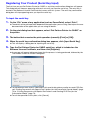
Registering Your Product (Serial Key Input) ........................................................ 71
To input the serial key...................................................................................................... 71
Printing Documents with Special Dot Patterns and Creating PPG Files ............... 72
Dot Pattern Printer for CASIO Operating Precautions......................................... 72
Printing Documents with Special Dot Patterns
(for the PowerPoint Control Mode)................................................................... 72
To print a document with special dot patterns for
use in the PowerPoint Control Mode ........................................................................... 72
Printing Documents with Special Dot Patterns and Creating PPG Files
(for the Presentation Mode) .............................................................................. 74
To print a documents with special dot patterns and generate a PPG file for
Presentation Mode use ............................................................................................... 74
Configuring Advanced Settings on the Dot Pattern Printer for
CASIO Dialog Box ............................................................................................ 76
Checking Your Dot Pattern Printer for CASIO Version ........................................ 77
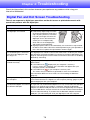
Chapter 4: Troubleshooting ......................................................................... 78
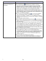
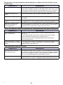
Digital Pen and Dot Screen Troubleshooting.......................................................... 78
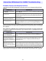
Interactive Whiteboard for CASIO Troubleshooting ............................................... 81
Probable Causes and Required Actions.............................................................. 81
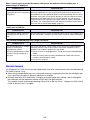
Known Issues....................................................................................................... 82
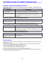
Dot Pattern Printer for CASIO Troubleshooting ...................................................... 83
Probable Causes and Required Actions.............................................................. 83
Known Issues....................................................................................................... 83
Chapter 5: Appendix ..................................................................................... 84
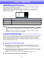
DSPD Management Functions................................................................................. 84
Caring for the Dot Screen ........................................................................................ 84
To clean the front of the dot screen..................................................................... 84
To clean the back of the dot screen .................................................................... 85
Stowing the Dot Screen ........................................................................................... 85
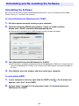
Uninstalling and Re-installing the Software ............................................................ 86
Uninstalling the Software ..................................................................................... 86
To uninstall Interactive Whiteboard for CASIO ................................................................. 86
To uninstall the DSPD ..................................................................................................... 86
To uninstall Dot Pattern Printer for CASIO ....................................................................... 87
Re-installing the Software.................................................................................... 87
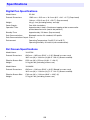
Specifications ........................................................................................................... 88
Digital Pen Specifications .................................................................................... 88
Dot Screen Specifications ................................................................................... 88
4
z Anoto and the Anoto logotype are trademarks of Anoto Group AB (Sweden).
z Microsoft, Windows, Windows Vista, and PowerPoint are trademarks of Microsoft Corporation in the
United States and other countries.
z “Bluetooth” is the trademark of Bluetooth SIG, Inc.
z Intel is a trademark or registered trademark of Intel Corporation in the United States and other
countries.
z Other company and product names may be registered trademarks or trademarks of their respective
owners.
z The contents of this manual are subject to change without notice.
z Copying of this manual, either in part or its entirety, is forbidden. You are allowed to use this manual
for your own personal use. Any other use is forbidden without the permission of CASIO COMPUTER
CO., LTD.
z CASIO COMPUTER CO., LTD. shall not be held liable for any lost profits or claims from third parties
arising out of the use of this product or this manual.
z CASIO COMPUTER CO., LTD. shall not be held liable for any loss or lost profits due to loss of data
caused by malfunction or maintenance of this product, or due to any other reason.
z The screen shots shown in this manual are representative facsimiles produced for explanation
purposes, and may differ from the displays produced by the actual product.
5
Introduction
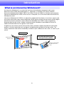
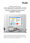
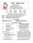
What is an Interactive Whiteboard?
An Interactive Whiteboard is a system that consists of the following components: dot screen,
documents that include special dot patterns*1, digital pen, a computer with special software
(Interactive Whiteboard for CASIO, DSPD, Dot Pattern Printer for CASIO*2) installed, and a projector.
Interactive Whiteboard for CASIO, which runs on a computer, acts as the front end of the Interactive
Whiteboard system.
Interactive Whiteboard for CASIO is an education support tool that displays in real time*3 figures and
text written on the dot screen with the digital pen. Since figures and text can be written with the digital
pen directly onto the computer screen (Interactive Whiteboard for CASIO screen) image being
projected onto the dot screen, students and presentation attendees are provided with easier to
understand information that has greater visual impact.
A digital pen can even be used to write on documents printed on paper prepared with special dot
patterns, with the handwritten text and figures immediately being shown on the dot screen. This
makes handwritten information immediately available to your audience on the screen, as soon as you
write it.
Dot screen
Document printed on paper
with special dot patterns
Write directly onto
the dot screen.
Writing on a document is
also reflected on the
screen.
6
*1 Documents printed using Dot Pattern Printer for CASIO. If you use Dot Pattern Printer for CASIO to
print paper versions of the same contents (such as PowerPoint files) as the slides to be projected
on the dot screen during a presentation, you can control the presentation (page changes, writing
on pages, etc.) using digital pen operations on the printed pages.
A separate Anoto Qualified Printer or an Anoto Tested Printer is required to print documents with
special dot patterns. Using another type of printer to print documents with special dot patterns can
result in incorrect printing of dot patterns and abnormal colors.
Visit the website below for the latest information about Anoto Qualified Printers and Anoto Tested
Printers (as of February 2013).
http://www.anoto.com/lng/en/pageTag/page:products/mode/sublist/documentId/1001/#Print
*2 Interactive Whiteboard for CASIO, DSPD, and Dot Pattern Printer for CASIO are based on Anoto
digital pen and paper technology. Anoto digital pen and paper technology are protected by over
200 global patents, including those shown below, which are the property of Anoto AB.
US6663008, US7172131, US7248250, US7281668, JP3872498, JP3842283, CN1595440,
SE517445, RU2256225, AU773011
For details about Anoto digital pen and paper technology, visit the Anoto website
(http://www.anoto.com/).
*3 Certain communication environments, computer specifications, and other specifications may
cause a certain amount of time lag before contents appear on the screen. Input data can be
corrupted if digital pen communication is interfered with by another nearby digital device, wireless
device, etc.
7
About this manual
This manual is divided into five chapters. The table below describes the main topics covered in each
chapter.
Chapter
Main Topics
Chapter 1:
Getting Ready
Chapter 1 explains the three steps below, which you need to perform to get ready to
use Interactive Whiteboard.
1 Preparing the digital pen
2 Installing the software
3 Setting up the dot screen, projector and computer
Chapter 2:
Using Interactive
Whiteboard for CASIO
Chapter 2 covers the Interactive Whiteboard for CASIO functions described below.
1 Presenting a slideshow using PowerPoint as-is (PowerPoint Control Mode). This
part explains how to change the page and write information onto pages by using
the digital pen to write onto the screen or onto a document page printed with
special dot patterns.
2 Presenting a slideshow using a special format (PPG file), which enables the use of
a powerful collection of tools for writing on each page (Presentation Mode). This
part explains how to change the page and write information onto pages by using
the digital pen to write onto the screen or onto a document page printed with
special dot patterns (including operation palette for students).
3 Writing directly onto a captured computer screenshot (Capture & Draw Mode). This
part explains how to use the digital pen to write directly onto a computer screen
shot being projected onto the dot screen.
Chapter 3:
Using Dot Pattern Printer
for CASIO
Chapter 3 explains the operations below, which are performed using Dot Pattern
Printer for CASIO.
1 Printing a PowerPoint file as a document with special dot patterns, which can be
used to perform slideshow operations in the Interactive Whiteboard for CASIO
PowerPoint Control Mode.
2 Printing a printable file as a document with special dot patterns and output a PPG
file. The PPG file can be used to conduct a slideshow in the Interactive Whiteboard
for CASIO Presentation Mode, and the printed document can be used to perform
slideshow operations in the Presentation Mode.
Chapter 4:
Troubleshooting
Chapter 4 explains what you need to do when you run into problems while using
Interactive Whiteboard. The information in this chapter is divided into three sections:
“Digital Pen and Dot Screen”, “Interactive Whiteboard for CASIO”, and “Dot Pattern
Printer for CASIO”.
Chapter 5:
Appendix
This chapter includes supplementary information about DSPD (digital pen driver
software), how to care for and store the dot screen, how to uninstall and reinstall the
software, and specifications.
8
Chapter 1:
Getting Ready
This chapter explains what you need to do to get ready to use Interactive Whiteboard.
General steps for getting ready are described below.
(1) Preparing the digital pen (page 10)
An Anoto digital pen is an input device for performing mouse operations on the computer
whose screen image is being projected from a projector, and for writing or drawing on the dot
screen or on documents printed on paper with special dot patterns. Perform the procedures
under “Preparing the Digital Pen” (page 10) using the digital pen that comes with this system or
an optionally available DP-301 digital pen.
(2) Installing the software (page 18)
Download the required software from the CASIO website and install it on your computer.
(3) Setting up the dot screen, projector and computer (page 23)
Set up the dot screen, projector, and computer in appropriate locations and then project an
image of the computer screen onto the dot screen.
9
Preparing the Digital Pen
Perform procedures in this section using the digital pen that comes with this system or an optionally
available digital pen.
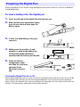
To load a battery into the digital pen
1.
Cover the nib end of the digital pen with the pen cap.
2.
Slide the lock lever downwards (away
from the pen nib) and then open the
battery cover.
3.
If there is a dead battery in the pen,
remove it.
4.
Making sure the positive (+) and
negative (–) ends of the battery are
facing in the proper directions,
carefully load the battery into the pen.
5.
Close the battery
compartment cover
and slide the lock lever
upwards (in the
direction of the pen
nib).
Lock lever
Turning the Digital Pen On or Off
Removing the digital pen cap will cause it to turn on, and replacing the cap will cause it to turn off. Be
sure to replace the cap when you are not using the digital pen. If you leave the cap off, digital pen
power will turn off automatically if you do not perform any operation with it for about seven and a half
minutes. To restore power, replace the cap and then remove it.
10
Replacing the Pen Nib
The digital pen comes with a stylus nib pre-installed. This means you do not need to replace the pen
nib before using it for the first time. Replace the nib in the cases described below.
z To install the ballpoint pen refill for writing onto paper documents printed on paper with special dot
patterns
z To replace a used up or damaged nib with a refill
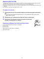
To replace the pen nib
1.
Gently grasp the pen nib currently installed in the digital pen and carefully pull it
out.
z If you experience problems pulling out the nib, try using needle-nose pliers. Again, grasp
gently and pull carefully.
2.
Taking care not to damage the refill pen nib, insert it into the pen.
3.
Gently press the nib down on a piece of paper to ensure that
the nib is inserted as far as it will go.
Replacement Ballpoint Pen Refills and Stylus Refills
Use of the ballpoint pen refills below is supported.
z LAMY M21
z Cross 8518-4
Use of the stylus refills below is supported.
z PLUS 423-063
11
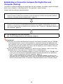
Establishing a Connection between the Digital Pen and
Computer (Pairing)
To establish a connection between the digital pen and your computer, you need to register the digital
pen on your computer as a Bluetooth device. This operation is called “pairing”.
General steps for pairing are described below.
(1) Check your computer system environment.
Check to make sure that your computer system environment satisfies the required conditions
(“Minimum Computer System Requirements”, page 17).
(2) Connect a Bluetooth adapter to your computer.
Connect a commercially available Bluetooth adapter that supports the Bluetooth version 2.0
HID (Human Interface Device) profile to your computer. See “To connect a Bluetooth adapter to
your computer” (page 13).
(3) Pair the digital pen with your computer.
See “To pair the digital pen with your computer” (page 14).
Important!
z Microsoft stack (Microsoft Bluetooth Enumerator and Generic Bluetooth Radio) or TOSHIBA
stack Bluetooth drivers can be used to establish a connection between the digital pen and
your computer. If you are using a commercially available Bluetooth adapter connected to your
computer, do not install the driver that comes with the adapter on your computer. Doing so
can cause digital pen operational problems.
z If you want to use a Bluetooth adapter that is built in on your computer, check to see if the
Bluetooth driver is Microsoft stack, TOSHIBA stack, or something else.
– You can use the built-in Bluetooth adapter if its driver is Microsoft stack or TOSHIBA stack.
In this case, turn on the built-in Bluetooth adapter and then proceed with the procedure
under “To pair the digital pen with your computer” (page 14).
– You will not be able to use your computer’s built-in Bluetooth adapter if its driver is not
Microsoft stack or TOSHIBA stack. In this case, turn off the built-in Bluetooth adapter and
perform the procedure under “To connect a Bluetooth adapter to your computer” below.
12
To connect a Bluetooth adapter to your computer
1.
Obtain a commercially available Bluetooth adapter and connect it to your
computer.
z The first time you connect a Bluetooth adapter to your computer, the Windows standard driver
will be installed automatically.
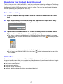
2.
Click the Bluetooth icon that appears in your computer’s task tray.
z If the Bluetooth icon does not appear in the Windows XP task tray, perform the following
operation on your computer: [Start] 3 [Control Panel] 3 [Bluetooth Devices]. Next, proceed
with step 4, below.
3.
Windows XP, Windows 8: Select “Open Bluetooth Settings”.
Windows Vista, Windows 7: Select “Open Settings”.
z This will display the “Bluetooth Settings” dialog box.
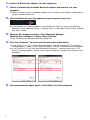
4.
Click the “Hardware” tab and check the points described below.
z In the “Devices” list, click “Generic Bluetooth Radio”, and then confirm that “This device is
working properly.” appears in the “Device Properties” text box at the bottom of the dialog box.
z In the “Devices” list, click “Microsoft Bluetooth Enumerator”, and then confirm that “This
device is working properly.” appears in the “Device Properties” text box at the bottom of the
dialog box.
5.
B
After confirming the above points, click [OK] to close the dialog box.
13
To pair the digital pen with your computer
1.
Click the Bluetooth icon in your computer’s task tray.
z If the Bluetooth icon is not shown in the Windows XP task tray, perform the operation below
on your computer.
1 [Start] 3 [Control Panel] 3 [Bluetooth Devices]
2 On the “Bluetooth Devices” dialog box that appears, click the “Options” tab, and then
select the check box next to “Show the Bluetooth icon in the notification area”.
3 Click [OK] to close the dialog box.
2.
Click the Bluetooth icon and a menu will appear.
Windows XP: Select “Add a Bluetooth Device”.
z This will start up the “Add Bluetooth Device Wizard”.
Windows Vista, Windows 7: Select “Add a Device”.
z This will start up the “Add Device Wizard”.
Windows 8: Advance directly to step 4.
3.
Windows XP: Select the check box next to “My devices is set up and ready to be
found” and then click [Next].
Windows Vista, Windows 7: Advance to step 4.
4.
Remove the cap from one digital pen that you want to pair with the computer.
z Your computer will search for a Bluetooth device, and “ADP-301B” will appear on the dialog
box.
Windows XP
Windows Vista, Windows 7
5.
B
Select “ADP-301B” and then click [Next].
14
6.
Windows XP: Select “Use the passkey found in the documentation” and then
input single-byte characters for the passkey.
Windows Vista, Windows 7, Windows 8: Select “Enter the pairing code for the
device” and then input single-byte characters for the passkey.
Windows XP
Windows Vista, Windows 7
z The pass keys for digital pens are shown below.
Digital pen included with the YA-W72M or YA-W82M: 0000
Optional CASIO DP-301 digital pen: 0000
7.
Click [Next].
z Windows XP: After pairing is complete, “Completing the Add Bluetooth Device Wizard” is
displayed.
Windows Vista, Windows 7: After pairing is complete, “This device has been successfully
added to this computer” is displayed.
8.
B
Windows XP: Click [Finish] to close the dialog box.
Windows Vista, Windows 7: Click [Close] to close the dialog box.
Windows 8: Exit “PC Settings”.
15
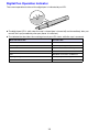
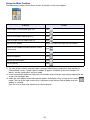
Digital Pen Operation Indicator
The current operational status of the digital pen is indicated by an LED.
z The digital pen LED is unlit when the cap is closed (pen is turned off) and immediately after you
remove the cap (immediately after pen power is turned on).
z The table below describes the meaning of each pen LED status while the cap is removed.
When the LED is this:
It means this:
Unlit
Idle status
Alternating between on and off at three-second intervals
Bluetooth pairing standby
Unlit
Bluetooth connection standby
Lit three seconds
Bluetooth connection successful
Unlit
Bluetooth connection established
Flashing for eight seconds and then shutdown
Battery very low warning
Unlit
Power off
16
Installing the Software
The software described in the table below must be installed on a computer paired with the digital pen
in order to use Interactive Whiteboard.
Software Name
Description
DSPD
DSPD stands for “digital pen streaming product driver”. DSPD is driver software that
makes it possible to send data picked up by a digital pen to Interactive Whiteboard
for CASIO.
Interactive Whiteboard for
CASIO
Interactive Whiteboard for CASIO is software that projects an image from the
computer where it is running onto a dot screen, where mouse operations can be
performed using a digital pen. It also makes it possible to perform PowerPoint
presentation page operations by tapping the projection screen with a digital pen, and
to write with the digital pen into files. In addition, the digital pen can be used to
perform pen operations and to write on special paper with dot patterns that was
printed using Dot Pattern Printer for CASIO.
Dot Pattern Printer for
CASIO
Dot Pattern Printer for CASIO is a virtual printer driver that can be used to print
documents that embed special dot patterns into PowerPoint, Word, and other types
of documents so they can be used in an Interactive Whiteboard for CASIO
presentation, and saves them as PPG files*1.
*1 Special file format that can be opened in the Presentation mode (page 41) of Interactive
Whiteboard for CASIO.
Minimum Computer System Requirements
The table below describes the minimum computer system requirements for running the software
described above.
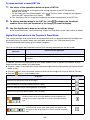
Operating Systems:Microsoft Windows® 8
Microsoft Windows® 7 SP1
Microsoft Windows Vista® SP2
Microsoft Windows® XP SP3 (32bit)
B
CPU:
Intel® Core 2 Duo 2.0GHz minimum
Memory:
At least 1GB as well as memory recommended for the operating system being
used.
Display:
1024 × 768 (32-bit color) minimum
Hard Disk:
At least 350MB of free space available
Digital Pen:
CASIO DP-301 (Manufactured by Anoto AB)
Bluetooth:
Bluetooth Version 2.0 Class 2
Bluetooth adapter that supports HID (Human Interface Device) profile required.
Bluetooth Stack:
Microsoft Bluetooth stack, TOSHIBA Bluetooth stack
Application:
PowerPoint® 2003/2007/2010
(Required when using the Interactive Whiteboard for CASIO PowerPoint Control
Mode.)
17
Minimum Computer System Precautions
z Configuring a computer system that meets the minimum requirements described above does not
necessarily guarantee that all hardware will operate normally.
z A system that does not satisfy the above minimum requirements or running other applications at the
same time as using the applications of this system can produce results that are different from those
described in this manual.
z Administrator rights are required to install software on your computer.
z Up to four digital pens can be used simultaneously at one time. However, only one pen can be used
in the PowerPoint Control Mode.
z Simultaneous use of other Bluetooth devices and/or use of more than four digital pens can produce
results that are different from those described in this manual.
To install the software
1.
Go to the CASIO website (http://www.casio-intl.com/support/download/).
2.
Download the zipped file of Interactive Whiteboard software.
3.
Double-click the downloaded zip file to open it.
4.
Using Windows Explorer, drag the “setup_en” folder from the zip file to your
computer’s local disk.
Important!
z Do not delete the “setup_en” folder, even after installation of all of the software is complete.
You will need it if you ever want to uninstall or re-install the software in the future.
18
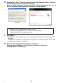
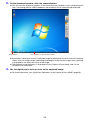
To start up the setup launcher
1.
Exit all programs currently running on your computer.
2.
Open the Interactive Whiteboard software “setup_en” folder and then
double-click “CASIO_InteractiveWhiteboardsetup.exe”.
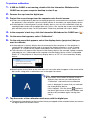
z Interactive Whiteboard for CASIO Setup Launcher will start up and display the dialog box
shown below.
[Install Interactive Whiteboard for
CASIO] becomes enabled after the
DSPD is installed.
Important!
z A Windows message dialog box may appear in place of the Setup Launcher when you
perform the above operation. What you need to do depends on your computer’s operating
system.
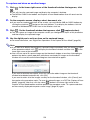
z Windows 8
If your computer does not have .NET Framework 3.5 installed, a Windows Features dialog box like
the one shown below may appear when you perform step 2, above.
If this happens, perform the steps below.
(1) Connect your computer to the Internet (if it is not already connected).
(2) If the “Program Compatibility Assistant” dialog box appears, click “Install using compatibility
settings”.
(3) On the Windows Features dialog box, click “Download and install this feature”.
(4) When the “The following feature was successfully installed:” message appears, click the [Close]
button.
B
19
z Windows XP
If the computer does not have .NET Framework 2.0 Service Pack 2 or higher installed, the following
error message will appear on its display at this time: “The application failed to initialize properly”. If
this happens, perform the procedure under “To install .NET Framework” (page 22) to start up the
setup launcher.
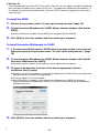
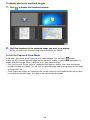
To install the DSPD
1.
Perform the procedure under “To start up the setup launcher” (page 19).
2.
On the Interactive Whiteboard for CASIO Setup Launcher window, click [Install
DSPD].
z After installation is complete, [Install DSPD] will change to [Uninstall DSPD].
3.
Click [Exit] to close the window, and then restart your computer.
To install Interactive Whiteboard for CASIO
1.
If the Interactive Whiteboard for CASIO Setup Launcher window is not currently
displayed, perform the procedure under “To start up the setup launcher” (page
19).
2.
On the Interactive Whiteboard for CASIO Setup Launcher window, click [Install
Interactive Whiteboard for CASIO].
z Carefully read the contents of the end user license agreement that appears.
3.
To agree to be bound by the terms of the license agreement and start
installation, click [I agree].
z Note that you will not be able to use Interactive Whiteboard for CASIO unless you agree to be
bound by the terms of the license agreement.
z Clicking [I agree] will start installation.
z After installation is complete, [Install Interactive Whiteboard for CASIO] will change to
[Uninstall Interactive Whiteboard for CASIO]. Also, the [Uninstall DSPD] option will become
disabled at this time.
4.
B
Click [Exit] to close the window, and then restart your computer.
20
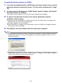
To install Dot Pattern Printer for CASIO
1.
If the Interactive Whiteboard for CASIO Setup Launcher window is not currently
displayed, perform the procedure under “To start up the setup launcher” (page
19).
2.
On the Interactive Whiteboard for CASIO Setup Launcher window, click [Install
Dot Pattern Printer for CASIO].
z Carefully read the contents of the end user license agreement that appears.
3.
To agree to be bound by the terms of the license agreement and start
installation, click [I agree].
z Note that you will not be able to use Dot Pattern Printer for CASIO unless you agree to be
bound by the terms of the license agreement.
z Clicking [I agree] will start installation.
z After installation is complete, [Install Dot Pattern Printer for CASIO] will change to [Uninstall
Dot Pattern Printer for CASIO].
4.
Click [Exit] to close the window, and then restart your computer.
Note
z Depending on the operating system running on your computer, clicking [I agree] in step 3 of
the procedure above may cause the dialog box shown below to appear. In this case, click
[Continue Anyway].
z Depending on the operating system running on your computer, clicking [I agree] in step 3 of
the procedure above may cause the “Windows Security” dialog box shown below to appear. If
it does, click [Install this driver software anyway].
21
To install .NET Framework
Important!
z Perform the procedure below only if the error message “The application failed to initialize
properly” appears in step 2 of the procedure under “To start up the setup launcher” (page 19).
1.
In the “dotnet” folder located inside the “setup_en” folder, double-click
“dotnetfx20.exe”.
Note
z The next two steps are not required if you are running the Windows XP English version.
2.
From the Microsoft Download Center, download the .NET Framework 2.0 Service
Pack 2 Language Pack that matches the language of the Windows XP version
your computer is running.
3.
Install the Language Pack you downloaded.
Checking for Proper Installation
After installing all of the software, restart your computer and check the points below.
z Whenever you start up your computer, DSPD will start up automatically and become resident in
your task tray. If DSPD is installed correctly, the DSPD icon ( ) will be displayed in the task tray.
z If Interactive Whiteboard for CASIO is installed correctly, the Interactive Whiteboard for CASIO icon
will be displayed on your computer desktop.
z If Dot Pattern Printer for CASIO is installed correctly, “Dot Pattern Printer for CASIO” will be
displayed in the “Printers” list on the print dialog box that appears when you execute the [Print] item
in an application (usually on the [File] menu).
Note
z The first time you start up Interactive Whiteboard for CASIO and the first time you execute a
print operation with Dot Pattern Printer for CASIO, you will be prompted for input of the serial
key. The serial key is located in the Software License Certificate that comes with this system.
22
Setting Up the Dot Screen, Projector, and Computer
This section explains how to connect a computer that has the required software installed to a
projector, and how to project computer screen images onto the dot screen.
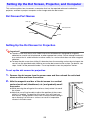
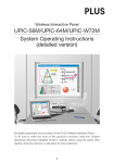
Dot Screen Part Names
Roll
End cap
End cap
Anti-slack wire
End bar
Screen
Setting Up the Dot Screen for Projection
Important!
z The dot screen that comes with CASIO Interactive Whiteboard is designed for magnetic
adhesion to a metal wall, blackboard, or other appropriate surface. Do not attempt to attach it
to a surface that is soiled with dust or other matter, or a surface that does not allow magnetic
adhesion.
z To keep the dot screen from falling if it detaches from the mounting surface due to impact, be
sure to use the provided safety hook to secure the dot screen to the surface. For details, see
steps 4 and 5 of the procedure under “To set up the dot screen for projection” below.
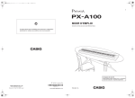
To set up the dot screen for projection
1.
Remove the dot screen from the screen case and then unhook the anti-slack
wires on either end from the end bar.
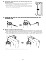
2.
Affix the magnetic end bar of the dot screen to a vertical
surface (metal wall, blackboard, etc.) and gradually unroll
the screen.
z While pressing the roll against the surface, slowly rotate it to unroll
the screen.
z Note that you will not be able to adjust the position of the screen
while it is unrolled. To reposition the screen, first roll it back up
onto the roll. Pulling the dot screen from a surface without rolling it
up or allowing it to fall from a surface can result in irreparable
creases in the dot screen.
End bar
23
3.
Completely unroll the screen and affix the magnetic roll to
the metal surface.
z Check to make sure that the dot screen will not separate from the
surface to which it is affixed when you release the roll.
z Note that when the screen is cold it may not flatten out completely,
which makes it very possible that it will become detached and fall
from the surface you attaching it to.
4.
Pull out the anti-slack wire of the top end cap and pass the safety hook wire
through the loop.
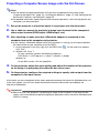
5.
Secure the safety hook to the surface.
z If you are affixing the dot screen to a blackboard that is mounted on a wall, insert the safety
hook into the space between the blackboard and the wall as shown in the illustration below.
z If you are affixing the dot screen to a surface where there is no space that you can use for the
safety hook, secure the safety hook to the wall using the screw that comes with the screen.
z Pull on the safety wire to confirm that the hook is secure.
24
Projecting a Computer Screen Image onto the Dot Screen
Note
z Do not perform the procedure below until you have completed all of the steps under:
“Preparing the Digital Pen” (page 10), “Installing the Software” (page 17), and “Setting Up the
Dot Screen, Projector, and Computer” (page 23).
z For detailed information about projector and computer operations, refer to the projector and
computer user documentation.
1.
Set up the projector in a location where it can project onto the dot screen.
2.
Use a cable to connect the projector’s image input terminal to the computer’s
video output terminal (RGB output, HDMI output, etc.)
3.
After checking to make sure that a Bluetooth adapter is connected to the
computer turn on the computer and projector.
z If you connect a Bluetooth adapter while your computer is running, you will need to perform
the steps below on your computer to restart DSPD.
1 In your computer’s task tray, right-click the DSPD icon ( ). On the menu that appears,
click “Exit”.
2 Windows XP, Vista, 7:
On your computer, perform the following sequence:
Click [Start] 3 [All Programs] 3 [dnp] 3 [dspd] 3 [dspd].
Windows 8:
On the Start screen, click the [dspd] tile.
4.
On the projector, adjust the zoom setting and adjust the location of the projector
so the image it is projecting fits within the dot screen area.
5.
On the projector, configure the required settings to specify video output from the
computer as the input source.
At this point you have completed all the steps required to prepare the Interactive Whiteboard for use.
In the next chapter, you will learn about the powerful features and functions provided by the
Interactive Whiteboard.
Important!
z Note that even if the projector is projecting an image of the computer screen onto the dot
screen, you will not be able to perform digital pen operations unless Interactive Whiteboard for
CASIO is running.
B
25
Chapter 2:
Using Interactive Whiteboard for CASIO
This chapter provides detailed explanations about how to use the features and functions of the
Interactive Whiteboard when conducting presentations. Operations are mainly performed using
Interactive Whiteboard for CASIO software running on a computer.
Interactive Whiteboard for CASIO Overview
This section provides an overview of what Interactive Whiteboard for CASIO (IWB for CASIO) allows
you to do, along with initial settings (product registration and calibration) you need to configure and
basic operational procedures.
Interactive Whiteboard for CASIO Modes
IWB for CASIO has four modes, each of which is described below.
Mouse Control Mode
This mode lets you use the digital pen in place of a mouse to perform operations directly on the image
being projected onto the dot screen.
PowerPoint Control Mode (Supports use of one digital pen.)
This mode is for conducting slideshow presentations of PowerPoint files using PowerPoint. IWB for
CASIO can be used to perform slideshow operations (page changes, writing on pages, etc.) with the
digital pen on the dot screen or on printed documents with special dot patterns.
Presentation Mode (Supports simultaneous use of up to four digital pens.)
This mode is for conducting presentations using special format (PPG) files generated from
PowerPoint, Word, PDF, and other types of files. This mode supports the operations described below.
z Slideshow operations (page changes, writing on pages, etc.) with the digital pen on the dot screen
or on printed documents with special dot patterns.
z As with PowerPoint file slideshow presentations, the Pen tool or Marker Pen tool can be used for
writing into the image. The following operations are also supported: shape, line, and arrow drawing;
image file pasting; relocation, zoom, and delete of objects inserted into a page; appending of a
blank page at the end of the slideshow, etc.
z Saving of content inserted during a slideshow to a PPG file. After re-opening a PPG file, inserted
content can be edited (relocated, zoomed, deleted) as desired.
z A choice of slideshow views: Full-screen view or window view.
Capture & Draw Mode (Supports simultaneous use of up to four digital pens.)
The Capture & Draw Mode lets you capture the computer screen image (being projected onto the dot
screen), and then write or draw figures into the captured image using the digital pen. Note that IWB for
CASIO toolboxes and windows are not included in the captured image. Captured images containing
inserted data can be stored as editable format (DST) files, or as non-editable image (png, jpg, or bmp)
files.
26
Registering Your Product (Serial Key Input)
The first time you start up IWB for CASIO, a serial key confirmation dialog box will appear. This dialog
box will keep on appearing with each startup until you input the serial key. The serial key is located in
the Software License Certificate that comes with this system. The serial key confirmation dialog box
will stop appearing once you input the serial key.
To input the serial key
1.
On your computer desktop, double-click the Interactive Whiteboard for CASIO
icon.
2.
When the serial key confirmation dialog box appears, click [Input Serial Key].
z This will display a dialog box for inputting the serial key.
3.
Type the Interactive Whiteboard for CASIO serial key, which is included on the
Software License Certificate, and then click [Register].
z This starts up Interactive Whiteboard for CASIO and displays the main toolbox in the upper
right corner of the screen. The Interactive Whiteboard for CASIO icon (
) will be displayed in
the task tray.
Main toolbox
z Next, perform the procedure described in “Calibration” below.
z If you want to exit IWB for CASIO, click the close (
) button in the lower right corner of the
main toolbox.
Calibration
Calibration is a process that teaches IWB for CASIO the projection position of the computer screen
image on the dot screen. After you complete the calibration process, you will need to perform it again
when there is a change in any one of the factors listed below.
z Dot screen setup position
z Projector setup position
z Projected image size setting
z Computer display settings (resolution or number of displays)
27
To perform calibration
1.
If IWB for CASIO is not running, double-click the Interactive Whiteboard for
CASIO icon on your computer desktop to start it up.
2.
Remove the cap from the digital pen.
3.
Project the screen image from the computer onto the dot screen.
z If there are multiple display devices (including projectors) connected to the computer, check if
the projector is the computer’s primary display device or secondary (or other) display device.
z If the projector is the computer’s primary display device, you can start calibration simply by
tapping the dot screen with the digital pen only. In this case, tap the dot screen with the digital
pen and then jump to step 7 of this procedure. Otherwise, proceed with step 4, below.
4.
In the computer’s task tray, click the Interactive Whiteboard for CASIO icon (
5.
On the menu that appears, select “Calibration”.
6.
On the sub-menu that appears, select the display device (projector) that you
want to calibrate.
).
z If the projector is the only display device connected to the computer or if the projector is
connected to a laptop computer and an image of the laptop computer’s screen is being
projected, “A” will be the only option displayed on the sub-menu. In this case, select “A”.
z The sub-menu will appear when there are two display devices (for example, laptop computer
and projector, etc.) connected to the computer and the display device screen is expanded.
Select “A” if the projector is the primary display device, or “B” if it is the secondary display
device.
z Selecting the correct letter on the sub-menu will cause the letter to appear in the center of the
dot screen, along with a calibration mark in the upper left corner.
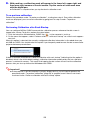
Note
z If the letter in the center of the dot screen is
different from the one you selected on the
“Calibration” sub-menu and no calibration
mark is displayed, it means that you selected
the wrong display device.
If this happens, click the close (
) button in
the lower right corner of the main toolbox and
perform this procedure again starting from
step 1.
7.
Tap the center of the calibration mark once with the digital pen.
z The position (coordinates) of the location where you tapped will be recorded when you remove
the digital pen from the dot screen.
28
8.
With each tap, a calibration mark will appear in the lower left, upper right, and
then lower right corners of the dot screen. Tap the center of each mark once
with the digital pen.
z Calibration is complete when you tap the fourth calibration mark.
To re-perform calibration
Perform the procedure under “To perform calibration”, starting from step 4. Even while calibration
marks are displayed, you can restart calibration by going back to step 4 under “To perform
calibration”.
Performing Calibration after Each Startup
You can configure IWB for CASIO to execute the calibration process whenever the dot screen is
tapped after startup. To do this, perform the steps below.
1 Click the Interactive Whiteboard for CASIO icon (
) in the computer’s task tray.
2 On the menu that appears, select “Perform calibration with each startup” so a check mark appears
next to it.
When this option is selected, the currently configured calibration information is discarded when you
exit IWB for CASIO. You should select this option if you frequently need to move the dot screen and/or
projector between presentations.
If there is no check mark next to “Perform calibration with each startup” (indicating that the option is
disabled, which is the initial default setting), calibration information produced by the last calibration
process is retained in memory. This means that tapping the dot screen will not start the calibration
process after you start up Interactive Whiteboard for CASIO.
Important!
z If the projector is not the computer’s primary display device, you will need to perform the
procedure under “To perform calibration” (page 28) as required, even if there is not check
mark next to the “Perform calibration with each startup” option.
29
Basic Operations
This section explains how to start up and exit IWB for CASIO, how to use the main toolbox, and how
to perform digital pen operations in the Mouse Control Mode.
To start up Interactive Whiteboard for CASIO
Use any one of the following operations.
z Windows XP, Vista, 7: Click [Start] 3 [All Programs] 3 [CASIO] 3 [Interactive Whiteboard for
CASIO] 3 [Interactive Whiteboard for CASIO].
z Windows 8: On the Start screen, click the [Interactive Whiteboard for CASIO] tile.
z On your computer desktop, double-click the Interactive Whiteboard for CASIO icon.
z On the computer screen image being projected onto the dot screen, tap with the digital pen.*1
z On a document with special dot patterns printed with Dot Pattern Printer for CASIO, tap with the
digital pen.*1
z Double-click a file (PPG or DST file) saved with IWB for CASIO.*2
*1 This startup method can be used when DSPD is running (DSPD icon
displayed in the task tray).
DSPD starts up automatically whenever you start up your computer and will be resident in your
task tray until you exit it manually.
*2 Double-clicking a PPG file will enter the Presentation Mode (page 41). Double-clicking a DST file
will enter the Capture & Draw Mode (page 51). For other startup methods, the initial startup mode
is the one that IWB for CASIO was in the last time you exited it.
To exit Interactive Whiteboard for CASIO
Use either one of the following operations.
z Click the close button (
) in the lower right corner of the main toolbox.
z In the computer’s task tray, click the Interactive Whiteboard for CASIO icon (
appears, click “Exit”.
B
30
). On the menu that
Using the Main Toolbox
The table below explains the functions of each of the tools in the main toolbox.
Main toolbox
To do this:
Do this:
Enter the Mouse Control Mode (page 32)*1
Click
.
Enter the PowerPoint Control Mode (page 33)*1
Click
.
Enter the Presentation Mode (page 41)*1
Click
.
Enter the Capture & Draw Mode (page 51)*1
Click
.
Move the main toolbox
Drag the blue bar at the top of the main toolbox.
Switch the main toolbox orientation between vertical
and horizontal
Click
.
Display software help*2
Click
.
Iconize the toolbox*3
Click
.
Minimize the main toolbox
Click
.
Exit the software
Click
.
*1 The icon of the currently selected mode is orange. Selecting any mode other than the Mouse
Control Mode causes a mode-specific toolbox to appear in addition to the main toolbox. For
details, see the explanations for each mode.
*2 In the Presentation Mode and Capture & Draw Mode, help cannot be accessed by tapping the dot
screen with the digital pen.
*3 Hides the main toolbox and mode-specific toolbox and displays only an icon for the current
mode. The icon to the right shows what is displayed in the Mouse Control Mode when the
toolbox is iconized.
Click this icon to return the toolbox to its normal display.
31
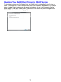
To view version information
In the computer’s task tray, click the Interactive Whiteboard for CASIO icon (
appears, click “About Interactive Whiteboard for CASIO”.
). On the menu that
Mouse Control Mode Digital Pen Operations
In the Mouse Control Mode, you can use the digital pen operations described below to perform mouse
operations.
To perform this mouse
operation:
Do this with the digital pen:
Click
Tap the dot screen once with the digital pen.
Double-click
Tap the same location (within three pixels) on the dot screen twice in succession with
the digital pen.
Right-click
Hold down the digital pen nib at the same location (within three pixels) on the dot
screen for at least one second. When [Right-click] appears on the display, remove the
digital pen from the dot screen.
Drag
Hold the nib of the digital pen against the dot screen as you drag it from one location
to another.
Right-drag
Hold down the digital pen nib at the same location (within three pixels) on the dot
screen for at least one second. When [Right-click] appears on the display, drag the
nib of the digital pen against the dot screen.
32
Using the PowerPoint Control Mode
The PowerPoint Control Mode is for conducting slideshow presentations with PowerPoint files*1. The
slideshow operations themselves are the same as those you perform when using PowerPoint. The
IWB for CASIO PowerPoint Control Mode supports the operations described below.
z Control of PowerPoint slideshow operations (page changes, writing on pages, etc.) using digital pen
operations on image projected on the dot screen.
z Control of PowerPoint slideshow operations (page changes, handwriting on pages, etc.) using
digital pen operations on documents printed with special dot patterns from PowerPoint files. Each
page of a document printed with special dot patterns is linked to a page of the PowerPoint file.
Tapping such a document page with the digital pen will jump to the corresponding page on the
computer.
*1 IWB for CASIO supports files created with PowerPoint 2003, PowerPoint 2007, and PowerPoint
2010. To conduct a slideshow with a PowerPoint file, the version of PowerPoint required to play
back the file must be installed on the computer.
Important!
z If you are using PowerPoint 2010, make sure your computer has Microsoft Office 2010
ServicePack 1 or higher installed. If it doesn’t, some IWB for CASIO functionality will be lost
when it is used in combination with PowerPoint 2010.
PowerPoint Control Mode Operational Flow
The following is the operational flow, up to actually conducting a slideshow, when using the
PowerPoint Control Mode.
(1) Prepare the PowerPoint file that you want to use for the slideshow.
(2) Use Dot Pattern Printer for CASIO to print the PowerPoint file.
This step is necessary if you plan to perform slideshow operations from printed documents with
special dot patterns.
For details, see “Printing Documents with Special Dot Patterns (for the PowerPoint Control
Mode)” (page 72).
(3) Start up IWB for CASIO, enter the PowerPoint Control Mode, and open the PowerPoint
file.
This will start the slideshow, and enable slideshow operation control by performing digital pen
operations on the dot screen or on a printed document with special dot patterns.
For more information, see “Conducting a Slideshow in the PowerPoint Control Mode” (page 34).
33
Conducting a Slideshow in the PowerPoint Control Mode
This section explains how to open a PowerPoint file and perform operations to control the slideshow.
To start a slideshow in the PowerPoint Control Mode
1.
Start up IWB for CASIO. Next, in the main toolbox, click
PowerPoint Control Mode.
to enter the
z This will display a PowerPoint Control Mode toolbox like the one shown below.
PowerPoint file drop area
2.
If you want, you can click
on the PowerPoint Control Mode toolbox and then
change the Margin settings.
z For more information, see “Changing the Margin Settings” on page 38.
3.
Drop the PowerPoint file that you want to use for the slideshow onto the
PowerPoint file drop area.
z This will display the “Paper settings” dialog box.
Note
z The settings of this dialog box correspond to printed
documents with special dot patterns calibration (digital
pen positioning). They do not affect dot screen
operations.
4.
Adjust the settings on the dialog box to match the paper settings you configured
when you printed the PowerPoint file as a printed document with special dot
patterns, and then click [Apply].
If you are not using a printed document with special dot patterns, click [Apply]
without changing any of the settings.
z Clicking [Apply] starts up the PowerPoint application and starts the slideshow from the first
page in the PowerPoint file. Slideshow operations are the same as those normally performed
with the PowerPoint application.
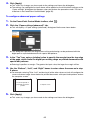
5.
Use the digital pen to perform page change operations, to write, and to perform
other operations on the dot screen or printed document with special dot
patterns.
z For more information, see “Digital Pen Operations during a Slideshow (Power Point Control
Mode)” (page 35).
B
34
To end a slideshow in the PowerPoint Control Mode
Advance the slideshow to the final page or select “End Show” on the PowerPoint application menu.
This will cause the PowerPoint window to be displayed as the top window.
z To restart a slideshow with the same PowerPoint file, perform the required PowerPoint application
operation to start the slideshow. If you do not want to restart the slideshow, exit the PowerPoint
application.
z If you want to start a slideshow of another PowerPoint file with the PowerPoint Control Mode,
perform the procedure starting from step 3 under “To start a slideshow in the PowerPoint Control
Mode” (page 34).
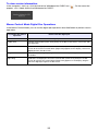
Digital Pen Operations during a Slideshow (Power Point Control Mode)
Dot Screen Operations
z You can use the digital pen to perform the mouse operations described below on the dot screen.
To perform this mouse
operation:
Do this with the digital pen:
Click
Tap the dot screen once with the digital pen.
Double-click
Tap the same location (within three pixels) on the dot screen twice in succession with
the digital pen.
Right-click
Hold down the digital pen nib at the same location (within three pixels) on the dot
screen for at least one second. When [Right-click] appears on the display, remove the
digital pen from the dot screen.
Drag
Hold the nib of the digital pen against the dot screen as you drag it from one location
to another.
Printed Document with Special Dot Pattern Operations
z You can use the digital pen to perform the mouse operations described below on a printed
document with special dot patterns.
To perform this mouse
operation:
Do this with the digital pen:
Click
Tap the document once with the digital pen.
Double-click
Tap the same location (within three pixels) on the document twice in succession with
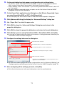
the digital pen.
Right-click
Hold down the digital pen nib at the same location (within three pixels) on the
document for at least one second. When [Right-click] appears at the mouse pointer
position on the computer screen (screen currently being projected onto the dot
screen), remove the digital pen from the document.
Drag
Hold the nib of the digital pen against the document as you drag it from one location
to another.
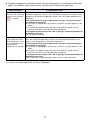
Important!
z When performing digital pen operations on a printed document with special dot patterns, the
mouse pointer operating range is narrower than when you perform digital pen operations on a
dot screen or mouse operations on a computer. Digital pen operations may not be possible in
the peripheral areas of the document. Also, even if the mouse pointer is within its allowable
range of movement with the digital pen, certain PowerPoint settings may make it impossible
to write or draw with the Pen tool.
35
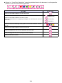
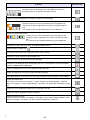
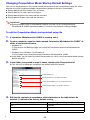
z If there is a “PowerPoint Operations” operation palette printed on the document, use the operation
palette to control the PowerPoint application.
To do this:
Tap this icon:
Select the PowerPoint slideshow function Arrow tool
(Ballpoint Pen)
Select the PowerPoint slideshow function Pen tool
(When using PowerPoint 2010, tapping the Ballpoint Pen or Felt Tip Pen icon will
select Pen.)
(Felt Tip Pen)
(Highlighter)
Select the color when drawing or writing with the PowerPoint slideshow function
Pen tool
Select the PowerPoint slideshow function Eraser tool
Display the page before the currently displayed slideshow page
Display the page after the currently displayed slideshow page
Display the Windows task bar
36
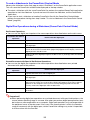
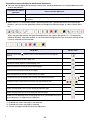
z Tapping or dragging on a printed document with special dot patterns is interpreted as described
below, in accordance with the tool currently selected with the PowerPoint application.
When you do this:
It is interpreted as this:
Tap the page of a printed
document with special dot
patterns when the Arrow
(
) is selected
Clicking with the arrow on the corresponding page of the PowerPoint file in the
PowerPoint application. However, the actual operation depends on the page currently
displayed in the PowerPoint application and the status of the page tapped with the
digital pen.
If the tapped document page is different from the page currently displayed by
the PowerPoint application:
z If the page you tapped does not include any animation, that page appears on the
display.
z If the page you tapped includes animation, the animation is played from the
beginning and then the corresponding page is displayed.
If the tapped document page is the same as the page currently displayed by the
PowerPoint application:
The next page is displayed.
Tap or drag on the page of
a printed document with
special dot patterns when
a Pen tool (Ballpoint Pen,
Felt Tip Pen, or
Highlighter*1) is selected
Clicking or dragging with the Pen tool on the corresponding page of the PowerPoint
file in the PowerPoint application. However, the actual operation depends on the
page currently displayed in the PowerPoint application.
If the tapped document page is different from the page currently displayed by
the PowerPoint application:
z If the page you tapped does not include any animation, that page appears on the
display.
z If the page you tapped includes animation, the animation is played from the
beginning and then the corresponding page is displayed.
If the tapped document page is the same as the page currently displayed by the
PowerPoint application:
Data is input into the applicable page using the currently selected Pen tool.
*1 In the case if PowerPoint 2010, the Pen or Highlighter.
37
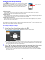
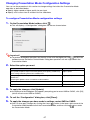
Changing the Margin Settings
Clicking
(Margin settings) on the PowerPoint Control Mode
toolbox displays a dialog box that can be used to change the
settings described below. These settings apply when using the
digital pen on a printed document with special dot patterns.
Margin settings icon
z Display settings
These settings can be used to specify the range of movement for the mouse cursor on the
computer screen (the screen projected on the dot screen).
z Paper settings
These settings can be used to specify the settings of the “Paper settings” dialog box (page 39) that
is displayed when you open a file in the PowerPoint Control Mode.
z Paper settings (advanced)
These settings can be used to specify the range of input written with the digital pen on a printed
document with special dot patterns.
Any changes to the above settings are applied when the procedure under “To start a slideshow in the
PowerPoint Control Mode” (page 34) is performed.
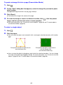
To configure display settings
1.
On the PowerPoint Control Mode toolbox, click
.
z This will display a “Display settings” dialog box like the one shown below.
z This dialog box specifies the range of movement of the mouse cursor on the computer screen
(currently being projected on the dot screen) when performing operations with the digital pen
on a printed document with special dot patterns.
2.
In the “Top” box, enter a value that specifies the top margin (which limits cursor
movement) as the number of pixels from the top of the computer screen.
z For example, enter 0 if you want the cursor to be able to move up to the top edge of the
computer screen. If you want to limit cursor movement up to 20 pixels from the top edge of
the screen, enter 20.
38
3.
Use the “Bottom”, “Left”, and “Right” boxes to enter values the same as in step
2, above.
z For example, entering 30 for “Left” and leaving all of the other values set to 0 will configure the
cursor movement range shown below for printed documents with special dot patterns and on
the computer screen.
Document printed on
paper with special dot
patterns
4.
Computer screen
Click [Apply].
z This saves any changes you have made to the settings and closes the dialog box.
To configure paper settings
1.
On the PowerPoint Control Mode toolbox, click
2.
Click the “Paper settings” tab.
.
z This will display a “Paper settings” dialog box like the one shown below.
3.
Configure paper size, orientation, and type settings when printing a PowerPoint
file as a printed document with special dot patterns.
Paper Size: A4, A3, A5, B4 (JIS), B5 (JIS), Legal (8.5inch × 14inch), Letter
Orientation:
Paper Type:
Landscape
Slides
Portrait
39
Notes
4.
Click [Apply].
z This saves any changes you have made to the settings and closes the dialog box.
z The settings you configured in step 3 above will be applied as the initial default settings on the
“Paper settings” dialog box that appears when you perform the procedure under “To start a
slideshow in the PowerPoint Control Mode” (page 34).
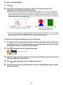
To configure advanced paper settings
1.
On the PowerPoint Control Mode toolbox, click
2.
Click the “Paper settings (advanced)” tab.
.
z This will display a “Paper settings (advanced)” dialog box like the one shown below.
z This dialog box specifies the range where writing and drawing can be performed with the
digital pen on a printed document with special dot patterns.
3.
In the “Top” box, enter a (relative) value to specify the margin from the top edge
of the page, which limits the digital pen writing range on printed documents with
special dot patterns.
z Entering 0 specifies no margin. The greater the input value, the larger the margin will be.
4.
Use the “Bottom”, “Left”, and “Right” boxes to enter values the same as in step
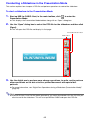
3, above.
z For example, entering 72 for “Left” and leaving all of the other values set to 0 will configure the
cursor movement range shown below for printed documents with special dot patterns and on
the computer screen.
Document printed on
paper with special dot
patterns
5.
Computer screen
Click [Apply].
z This saves any changes you have made to the settings and closes the dialog box.
40
Using the Presentation Mode
The Presentation Mode is for conducting presentations using special format (PPG) files generated
from PowerPoint, Word, PDF, and other types of files. This mode supports the operations described
below.
z Slideshow operations (page changes, writing on pages, etc.) with the digital pen on the dot screen
or on printed documents with special dot patterns
z As with PowerPoint file slideshow presentations, the Pen tool or Marker Pen tool can be used for
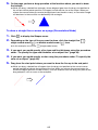
writing into the image. The following operations are also supported: shape, line, and arrow drawing;
image file pasting; relocation, zoom, and delete of objects inserted into a page; appending of a
blank page at the end of the slideshow, etc.
z Saving of content inserted during a slideshow to a PPG file
After re-opening a PPG file, inserted content can be edited (relocated, zoomed, deleted) as desired.
z A choice of slideshow views: full-screen view or window view
Presentation Mode Operational Flow
The following is the operational flow, up to actually conducting a slideshow, when using the
Presentation Mode.
(1) Prepare the PowerPoint, Word, PDF, or other file to be used as the source of the
slideshow, and (if you plan to perform slideshow operations from a printed document with
special dot patterns) print it using Dot Pattern Printer for CASIO.
(2) Use the file you prepared in step (1) above to create a PPG file.
You can perform the above two steps simultaneously using Dot Pattern Printer for CASIO. For
details, see “Printing Documents with Special Dot Patterns and Creating PPG Files (for the
Presentation Mode)” (page 74).
(3) Start up IWB for CASIO, enter the Presentation Mode, and open the PPG file.
This will start the slideshow, and enable slideshow operation control by performing digital pen
operations on the dot screen or on a printed document with special dot patterns.
For more information, see “Conducting a Slideshow in the Presentation Mode” (page 42).
41
Conducting a Slideshow in the Presentation Mode
This section explains how to open a PPG file and perform operations to control the slideshow.
To start a slideshow in the Presentation Mode
1.
Start up IWB for CASIO. Next, in the main toolbox, click
Presentation Mode.
to enter the
z This displays the Presentation Mode toolbox along with an “Open” dialog box.
2.
Use the “Open” dialog box to select the PPG file for the slideshow and then click
[Open].
z This will open the PPG file and display its first page.
Presentation Mode toolbox
Main toolbox
3.
Use the digital pen to perform page change operations, to write, and to perform
other operations on the dot screen or printed document with special dot
patterns.
z For more information, see “Digital Pen Operations during a Slideshow (Presentation Mode)”
(page 43).
Note
z In place of steps 1 and 2 of the above procedure, you could also double-click the PPG file you
want to use for the slideshow. This will start up IWB for CASIO and open the PPG file.
42
To select full-screen view or window view for a slideshow
In the Presentation Mode, you can select either full-screen view or window view for a slideshow. For
more information, see “Changing Presentation Mode Configuration Settings” (page 47).
Note that any time you change the view you will need to restart IWB for CASIO.
To end a slideshow in the Presentation Mode
In the lower right corner of the Presentation Mode toolbox, click the close (
) button
If you have written or drawn data into the PPG file or made other changes during the slideshow, a
dialog box will appear with the message, “Save presentation data before exiting?”.
– Click [Yes] to save. On the “Save As” dialog box that appears, specify a file name and storage
location and then click [Save].
– If you want to discard the changes without saving them, click [No].
Digital Pen Operations during a Slideshow (Presentation Mode)
This section provides brief explanations of the operations that can be performed with the digital pen
on the dot screen or on a printed document with special dot patterns. For details about each individual
operation, see “Tool Operations in the Presentation Mode and Capture & Draw Mode” (page 61).
Dot Screen Operations
You can use the digital pen to perform mouse click and drag operations on the dot screen.
To perform this mouse
operation:
Do this with the digital pen:
Click
Tap the dot screen once with the digital pen.
Drag
Hold the nib of the digital pen against the dot screen as you drag it from one location
to another.
In addition, you can click the Presentation Mode toolbox icons to perform the Presentation Mode
functions described in the table below.
z The term “page” in the table refers to the slideshow slide that is the target of the operation being
performed.
z The term “object” refers to content, a shape, or an image that has been added to a slideshow page
using an IWB for CASIO function.
z An asterisk (*) next to an icon indicates that the icon’s function can be performed from the
“Presentation Mode” operation palette on a printed document with special dot patterns.
z Only the
icon is a main toolbox icon.
To do this:
Select the Arrow tool
Click this icon:
(which can be used to advance to the next page by clicking)
*
Select the Pen tool (for pen input on the page)
*
Select the Marker Pen tool (for marker input on the page)
*
Select the Selection tool (for selecting objects on the page)
Select the Eraser tool (for deleting objects from the page)
43
*
To do this:
Click this icon:
Display the Shapes menu
Clicking an icon on the Shapes menu that appears will select a
drawing tool for the shape represented by the icon.
Display an “Open” dialog box for inserting an image file into the page
Display the Line Type Setting menu
Clicking an icon on the Line Type Setting menu that appears will
change the line type assigned to the currently selected write/draw
tool.
This setting can be changed individually for each digital pen.
*
Display the Color Setting menu
Clicking an icon on the Color Setting menu that appears will
change the color assigned to the currently selected write/draw
tool.
This setting can be changed individually for each digital pen.
*
Undo up to 10 of the last write, draw, or image-related operations
Redo operations undone with
Increase the zoom factor of the page view (150%, 200%, 300%)
*
Decrease the zoom factor of a zoomed page view
*
Select the Hand cursor tool (to drag a zoomed page)
*
Disable (or re-enable) page auto change (page 46) when a printed document with special dot
patterns is tapped with the digital pen
*
Display the page before the currently displayed slideshow page
*
Display the page after the currently displayed slideshow page
*
Add a blank page at the end of the currently opened PPG file (Up to 20 pages can be added.)
Display the Delete menu
The Delete menu contains three options: “Delete all objects on displayed page”, “Delete all
objects on all pages”, “Delete displayed page”. For details, see “Delete Menu Operations” (page
67).
Display the “Print” dialog box to print the currently open PPG file
Display the “Open” dialog box to open a PPG file
Display the Save File menu
The Save File menu contains three options: “Save ppg”, “Save image of displayed page”, “Save
images of all pages”. For details, see “Save File Menu Operations” (page 68).
B
44
Printed Document with Special Dot Pattern Operations
z You can use the digital pen to perform mouse click and drag operations on a printed document with
special dot patterns.
To perform this mouse
operation:
Do this with the digital pen:
Click
Tap the document once with the digital pen.
Drag
Hold the nib of the digital pen against the document as you drag it from one location
to another.
z When there is a “Presentation Mode” operation palette on a printed document with special dot
patterns, you can use the operation palette to change the slideshow page, to select certain tools,
etc.
When the operation palette on the printed document with special dot pattern is a “Presentation
Mode for Student” operation palette, it can be used to change the line type and color settings of the
currently selected write/draw tool.
To do this:
Select the Arrow tool
tapping)
Tap this icon:
(which can be used to advance to the next page by
*1
Increase the zoom factor of the page view
Decrease the zoom factor of a zoomed page view
*2
Select the Hand cursor tool (to drag a zoomed page)
*2
Select the Pen tool (for pen input on the page)
Select the Marker Pen tool (for marker input on the page)
Change the line type assigned to the currently selected write/draw tool
Change the color assigned to the currently selected write/draw tool
Select the Eraser tool (for deleting objects from the page)
Display the page before the currently displayed slideshow page
Display the page after the currently displayed slideshow page
Disable (or re-enable) page auto change (page 46) when a printed document with
special dot patterns is tapped with the digital pen
*1 Enabled only when the page is not zoomed.
*2 Enabled only when the page is zoomed.
*3 Can be changed individually for each digital pen.
B
45
*3
*3
Page Auto Change Feature of Printed Documents with Special Dot Patterns
An operation performed with the digital pen on any page of a printed document with special dot
patterns is interpreted as an operation on the corresponding PPG file page. A page auto change
feature causes the slideshow to jump automatically to the PPG file page that corresponds to any
printed document page that is tapped with the digital pen.
You can disable page auto change, if you want. Simply tap the
icon on the Presentation Mode
toolbox or on a printed document with special dot pattern operation palette. This will toggle page auto
change between enabled (
displayed as the Presentation Mode toolbox icon) and disabled (
displayed as the icon).
z While page auto change is enabled (
), tapping a page of a printed document with special dot
patterns that is different from the currently selected page will cause the current slideshow to jump
automatically to that page, regardless of which tool is currently selected.
z Regardless of whether page auto change is enabled or disabled, performing a tap or drag operation
on a page of a printed document with special dot patterns with the digital pen will cause the same
operation to be performed with the currently selected tool on the corresponding page of the
slideshow that is currently in progress. If the Pen tool is currently selected, for example, performing
a drag operation on a page of a printed document with special dot patterns that is different from the
page currently displayed by the slideshow will perform a draw operation on the corresponding page
of the slideshow. Note that while page auto change is disabled (
), you may end up performing
unintended operations (deletion of page objects with the Eraser tool, etc.) on a page that is currently
not displayed.
46
Changing Presentation Mode Configuration Settings
You can use the procedure in this section to change settings that affect the Presentation Mode
operation as described below.
z Specify higher speed or higher quality for pen input
z Specify a full-screen view or window view for slideshows
To configure Presentation Mode configuration settings
1.
On the Presentation Mode toolbox, click
.
z This will display a “Configuration” dialog box like the one shown below.
Important!
z To perform dialog box operations on the dot screen with the digital pen, tap
on the main
toolbox to enter the Mouse Control Mode. Dialog box operations are not supported in the
Presentation Mode.
2.
Select the option you want.
To do this:
3.
Select this option:
Give speed (response to pen movement) priority over quality (smoothness)
when writing or drawing with a Pen or Marker Pen
Higher speed
Give quality priority over speed when writing or drawing with a Pen or
Marker Pen
Selecting this option causes curved lines to be smoother.
Higher quality
Display slideshows in a full-screen view
Full-screen display
Display slideshows in a window view
Window display
To apply the changes, click [Update].
z In response to the dialog box that appears prompting you to restart IWB for CASIO, click [OK]
(which will not restart IWB for CASIO).
4.
To exit the “Configuration” dialog box, click [Close].
5.
To apply the changes you have made to settings, restart IWB for CASIO.
z You can also apply changes by clicking the close (
) button in the lower right corner of the
Presentation Mode toolbox to exit the Presentation Mode, and then clicking
to re-enter
the Presentation Mode.
47
Changing Presentation Mode Startup Default Settings
You can use the procedure in this section to edit the contents of the startup default setup file, which
specifies the initial Presentation Mode startup default settings of the items listed below.
z Startup default tool (Pen, Marker Pen, or Arrow)
z Startup default Pen color and line thickness
z Startup default Marker Pen color and line thickness
z Startup default Shapes color and line thickness
Important!
z Making changes to the startup default setup file runs the risk of causing Interactive
Whiteboard for CASIO operation problems. Exercise care whenever making changes.
To edit the Presentation Mode startup default setup file
1.
If Interactive Whiteboard for CASIO is running, exit it.
2.
On your computer, open the folder named “Interactive Whiteboard for CASIO” at
either of the locations below.
– Windows XP:
C:\Documents and Settings\{login user name}\My Documents\Interactive Whiteboard for
CASIO
– Windows Vista, Windows 7 or Windows 8:
C:\Users\{login user name}\Documents\Interactive Whiteboard for CASIO
z In the folder, you will find a file named Presentation.ini, which is the Presentation Mode startup
default setup file.
3.
In the folder you opened in step 2, above, double-click Presentation.ini.
z This will start up Notepad, and display the default setup file contents.
Startup default tool
Startup default Pen color and line thickness
Startup default Marker Pen color and line thickness
Startup default Shapes color and line thickness
4.
Edit the file contents in accordance with information in the table below. An
asterisk (*) indicates the factory default setting.
To select this as the startup default tool:
B
Change line under [MODE] to this:
Pen*
Type=pen
Marker Pen
Type=marker
Arrow
Type=presentation
48
To select this as the startup default Pen color:
Change first line under [PEN] to this:
Red*
Color=red
Blue
Color=blue
Black
Color=black
Yellow
Color=yellow
To select this as the startup default Pen line
thickness:
Change second line under [PEN] to this:
Fine*
Width=thin
Normal
Width=normal
Thick
Width=bold
Extra thick
Width=extrabold
To select this as the startup default Marker Pen
color:
Change first line under [MARKER] to this:
Red
Color=red
Blue
Color=blue
Black
Color=black
Yellow*
Color=yellow
To select this as the startup default Marker Pen
line thickness:
Fine
Change second line under [MARKER] to this:
Width=thin
Normal
Width=normal
Thick*
Width=bold
Extra thick
Width=extrabold
To select this as the startup default Shapes color:
Change first line under [SHAPES] to this:
Red
Color=red
Blue
Color=blue
Black*
Color=black
Yellow
Color=yellow
To select this as the startup default Shapes line
thickness:
Change second line under [SHAPES] to this:
Fine*
Width=thin
Normal
Width=normal
Thick
Width=bold
Extra thick
Width=extrabold
49
5.
After all of the edits are the way you want, save the file and close the Notepad
window.
Note
z When you save the file in step 5 of the above procedure, the initial factory default setting will
be automatically set for any item for which there is invalid text (a setting that is not included in
the table above) to the right of the equals (=) sign. For example, if “Width=red” is specified for
the Shapes line thickness setting, “thin” will automatically be applied as the startup default
setting.
z If, after you edit the startup default setup file, you have problems starting up Interactive
Whiteboard for CASIO, trash the edited Presentation.ini file and then restart Interactive
Whiteboard for CASIO. This will automatically generate a new Presentation.ini file configured
with factory default settings.
50
Using the Capture & Draw Mode
The Capture & Draw Mode lets you capture the computer screen image (being projected onto the dot
screen), and then write or draw on the captured image using the digital pen. Note that IWB for CASIO
toolboxes and windows are not included in the captured image. Captured images containing drawn or
written data can be stored as editable format (DST) files, or as non-editable image (png, jpg, or bmp)
files.
Capture & Draw Mode Operational Flow
This following is the operational flow for capturing a computer screen image and drawing on it in the
Capture & Draw Mode.
(1) Project the computer screen image you want to capture and draw on.
The primary computer display device must be the one being projected onto the dot screen. See
the “Important!” notes below.
(2) Start up IWB for CASIO, enter the Capture & Draw Mode, and perform the screen capture
operation.
(3) Draw on the captured image as desired.
As soon as you capture a screen image in the Capture & Draw Mode, the digital pen
automatically switches to a mode for drawing on the image. For details, see “Capturing and
Drawing on the Currently Displayed Computer Screen Image” (page 52).
Important!
z If the computer has multiple display devices connected (such as when a laptop computer is
connected to the projector), make sure that the primary display device of the computer is
being projected onto the dot screen. Computer screen capture in the Capture & Draw Mode
can only capture the computer’s primary display device.
z If the computer’s primary display device is not the one being projected onto the dot screen,
perform the required operation on the computer to change its display settings so that the
primary display device is being projected. After changing the computer’s display settings, be
sure to perform the operation under “To perform calibration” (page 28) again to re-calibrate.
51
Capturing and Drawing on the Currently Displayed Computer
Screen Image
Use the procedure below to capture an image of the computer screen being projected onto the dot
screen and to draw on the captured image.
To capture and draw on the currently displayed computer screen image
1.
On the computer screen, display the diagram or document you want to capture
and draw on.
2.
On the main toolbox, click
to enter the Capture & Draw Mode.
z This displays the Capture & Draw Mode toolbox along with the thumbnail window.
Thumbnail window
Capture & Draw Mode toolbox
Capture button
52
3.
On the thumbnail window, click the capture button.
z This will close the thumbnail window. At the same time, the computer screen you displayed in
step 1 (excluding IWB for CASIO toolboxes and windows) will be captured and displayed.
Image number
Outer boundary of captured image display
z A boundary is displayed around a captured image to differentiate it from the normal computer
screen. Also, an image number (indicating chronological order that the images were captured)
is displayed on the lower left corner of the image.
z The captured screen boundary is displayed only the Capture & Draw Mode, and it is not
included in the saved data.
4.
Use the digital pen to write or draw on the captured image.
z For more information, see “Digital Pen Operations in the Capture & Draw Mode” (page 56).
53
To capture and draw on another image
1.
Click
.
. In the lower right corner of the thumbnail window that appears, click
z This will close the captured image and display the computer’s desktop.
z The IWB for CASIO main toolbox and Capture & Draw Mode toolbox also will remain on the
display.
2.
On the computer screen, display a chart, document, etc.
z If you want an unobstructed view of the screen, you can hide the IWB for CASIO toolbox by
clicking the minimize (
) button on the main toolbox. To re-display the toolbox, click the
Interactive Whiteboard for CASIO icon in the Windows task bar.
3.
Click
. On the thumbnail window that appears, click
(capture button).
z This will capture an image of the computer screen you configured in step 2 of this procedure
and then display the captured image.
4.
Use the digital pen to write or draw on the captured image.
z For more information, see “Digital Pen Operations in the Capture & Draw Mode” (page 56).
Note
z If you want to re-display the previously captured image immediately after you close it in step 1
of the procedure above, click
to display the thumbnail window and then click
in the
lower right corner of the window.
z You can have up to 50 capture images on the thumbnail window at one time. Attempting to
perform the above capture operation while there are already 50 images on the thumbnail
window will cause the confirmation dialog box shown below to appear.
If you want to execute the capture, which will cause the oldest image on the thumbnail
window to be deleted automatically, click [OK].
If you want to retain all of the images currently on the thumbnail window, click [Cancel] and
then perform the procedure under “To save all captured images as a DST file (Capture & Draw
Mode)” (page 68). After that, click the close (
) button in the lower right corner of the
Capture & Draw Mode toolbox and then perform the procedure under “To capture and draw
on the currently displayed computer screen image” (page 52) again.
54
To display previously captured images
1.
Click
2.
Click the thumbnail of the captured image you want to re-display.
to display the thumbnail window.
z This will display the captured image whose thumbnail you clicked.
To exit the Capture & Draw Mode
In the lower right corner of the Capture & Draw Mode toolbox, click the close (
) button.
If there are any unsaved captured images on the thumbnail window, a confirmation dialog box will
appear with the message “Save “Capture & Draw” data before exiting?”.
– Click [Yes] to save. On the “Save As” dialog box that appears, specify a file name and storage
location and then click [Save]. This will save all captured images and anything drawn on the screen
to a single DST file.
– To discard all the images you captured in the current Capture & Draw Mode session and any data
currently drawn on the images, click [No] on the confirmation dialog box.
55
To open and edit a saved DST file
1.
Use either of the operations below to open a DST file.
– Use Windows Explorer to navigate to the storage location of the DST file and then
double-click the file.
– On the Capture & Draw Mode toolbox, click (
). Use the “Open” dialog box that appears,
select the DST file and then click [Open].
z This will display the first image (the image with the oldest capture date) in the DST file.
2.
To display another image in the DST file, click
to display the thumbnail
window. Next, click the thumbnail of the image you want to display.
3.
Use the digital pen to draw on or edit the image.
z For more information, see the following “Digital Pen Operations in the Capture & Draw Mode”.
Digital Pen Operations in the Capture & Draw Mode
This section provides brief explanations of the operations that can be performed with the digital pen
on the dot screen. For details about each individual operation, see “Tool Operations in the
Presentation Mode and Capture & Draw Mode” (page 61).
You can use the digital pen to perform mouse click and drag operations on the dot screen.
To perform this mouse
operation:
Do this with the digital pen:
Click
Tap the dot screen once with the digital pen.
Drag
Hold the nib of the digital pen against the dot screen as you drag it from one location
to another.
In addition, you can click the Capture & Draw Mode toolbox icons to perform the Capture & Draw
Mode functions described in the table below.
z The term “page” in the table refers to the captured image currently displayed on the Capture & Draw
Mode screen.
z The term “object” refers to content written or drawn on the image with a Pen or Marker Pen tool.
z Only the
icon is a main toolbox icon.
To do this:
Click this icon:
Select the Pen tool (for pen input on the page)
Select the Marker Pen tool (for marker input on the page)
Select the Selection tool (for selecting objects on the page)
Select the Eraser tool (for deleting objects from the page)
Display the Line Type Setting menu
Clicking an icon on the Line Type Setting menu that appears will
change the line type assigned to the currently selected write/draw
tool.
Display the Color Setting menu
Clicking an icon on the Color Setting menu that appears will
change the color assigned to the currently selected write/draw
tool.
56
To do this:
Click this icon:
Undo up to 10 of the last draw operations
Redo operations undone with
Increase the zoom factor of the page view (150%, 200%, 300%)
Decrease the zoom factor of a zoomed page view
Select the Hand cursor tool (to drag a zoomed page)
Display the thumbnail window
The two operations below can be performed with the
thumbnail window.
z Capture an image of the computer screen by clicking
the capture (
) button.
z Display a captured image by clicking its thumbnail.
Display the Delete menu
The Delete menu contains three options: “Delete all objects on displayed page”, “Delete all
objects on all pages”, “Delete displayed page”. For details, see “Delete Menu Operations” (page
67).
Display the “Print” dialog box to print the currently open DST file
Display the “Open” dialog box to open a DST file
Display the Save File menu
The Save File menu contains three options: “Save dst”, “Save image of displayed page”, “Save
images of all pages”. For details, see “Save File Menu Operations” (page 68).
57
Or
Changing Capture & Draw Mode Startup Default Settings
You can use the procedure in this section to edit the contents of the startup default setup file, which
specifies initial Capture & Draw Mode startup default settings of the items listed below.
z Startup default tool (Pen or Marker Pen)
z Startup default Pen color and line thickness
z Startup default Marker Pen color and line thickness
z Captured image boundary color and thickness (page 53)
Important!
z Making changes to the startup default setup file runs the risk of causing Interactive
Whiteboard for CASIO operation problems. Exercise care whenever making changes.
To edit the Capture & Draw Mode startup default setup file
1.
If Interactive Whiteboard for CASIO is running, exit it.
2.
On your computer, open the folder named “Interactive Whiteboard for CASIO” at
either of the locations below.
– Windows XP:
C:\Documents and Settings\{login user name}\My Documents\Interactive Whiteboard for
CASIO
– Windows Vista, Windows 7 or Windows 8:
C:\Users\{login user name}\Documents\Interactive Whiteboard for CASIO
z In the folder, you will find a file named DesktopDrawing.ini, which is the Capture & Draw Mode
startup default setup file.
3.
In the folder you opened in step 2, above, double-click DesktopDrawing.ini.
z This will start up Notepad, and display the default setup file contents.
Startup default tool
Startup default Pen color and line thickness
Startup default Marker Pen color and line thickness
Startup default captured image boundary color and thickness
B
58
4.
Edit the file contents in accordance with information in the table below. An
asterisk (*) indicates the factory default setting.
To select this as the startup default tool:
Change line under [MODE] to this:
Pen*
Type=pen
Marker Pen
Type=marker
To select this as the startup default Pen color:
Change first line under [PEN] to this:
Red*
Color=red
Blue
Color=blue
Black
Color=black
Yellow
Color=yellow
To select this as the startup default Pen line
thickness:
Change second line under [PEN] to this:
Fine*
Width=thin
Normal
Width=normal
Thick
Width=bold
Extra thick
Width=extrabold
To select this as the startup default Marker Pen
color:
Change first line under [MARKER] to this:
Red
Color=red
Blue
Color=blue
Black
Color=black
Yellow*
Color=yellow
To select this as the startup default Marker Pen
line thickness:
Fine
Change second line under [MARKER] to this:
Width=thin
Normal
Width=normal
Thick*
Width=bold
Extra thick
Width=extrabold
To select this as the capture image boundary
color:
Change first line under [SHAPES] to this:
Red
Color=red
Blue
Color=blue
Black*
Color=black
Yellow
Color=yellow
To select this as the capture image boundary
thickness:
1 pixel to 100 pixels
(Factory default: 20 pixels)
Change second line under [SHAPES] to this:
Width={line thickness value}
For example, to specify a 15-pixel thick line, specify:
“Width=15”.
59
5.
After all of the edits are the way you want, save the file and close the Notepad
window.
Note
z When you save the file in step 5 of the above procedure, the initial factory default setting will
be automatically set for any item for which there is invalid text or numbers (a setting that is not
included in the table above) to the right of the equals (=) sign. For example, if “Width=red” is
specified for the Marker Pen line thickness setting, “thick” will automatically be applied as the
startup default setting.
z If, after you edit the startup default setup file, you have problems starting up Interactive
Whiteboard for CASIO, trash the edited DesktopDrawing.ini file and then restart Interactive
Whiteboard for CASIO. This will automatically generate a new DesktopDrawing.ini file
configured with factory default settings.
60
Tool Operations in the Presentation Mode and
Capture & Draw Mode
The Presentation Mode toolbox and Capture & Draw Mode toolbox include some tools that are
common to both modes, and some tools that are unique to each mode. Among the common tools,
there are those whose operations are identical on both modes, and those whose operations are
slightly different in each mode. This section explains the tools that are available in each of the modes
and what operations they perform there.
Write/Draw Tool Operations
The operations in this section are the same in both the Presentation Mode and the Capture & Draw
Mode, except as specifically noted.
To write on a page with a Pen or Marker Pen
1.
Click
2.
If you want, you could specify a line type and line thickness using the procedure
under “To specify the type and thickness of an object line” (page 64).
3.
If you want, you could specify a color using the procedure under “To specify the
color of an object” (page 65).
4.
Perform a drag operation on the page to draw or write.
to use the Pen or
to use the Marker Pen.
To draw a circle, triangle or rectangle on a page (Presentation Mode)
1.
Click
2.
Depending on the type of shape you want to draw, tap one of the icons inside the
outline shapes (
) group or the filled shapes (
) group.
to display the Shapes menu.
z In this example, we will use
(filled triangle).
3.
If you want, you could specify a line type and line thickness using the procedure
under “To specify the type and thickness of an object line” (page 64).
4.
If you want, you could specify a color using the procedure under “To specify the
color of an object” (page 65).
z The color you specify here is applied to the outline of the shape if you selected an outline
shape in step 2 of this procedure, or both the outline and the fill if you selected a filled shape.
Note that specification of different outline and fill colors is not supported.
61
5.
On the page, perform a drag operation at the location where you want to draw
the triangle.
z While you drag, a dotted line rectangle, whose diagonal goes from the drag start position to
the current mouse pointer position, will appear to indicate the size of the shape. When you
release the mouse button (or remove the digital pen from the dot screen), an isosceles triangle
will be drawn in the area that was defined by the rectangle.
To draw a straight line or arrow on a page (Presentation Mode)
1.
Click
2.
Depending on the type of line you want to draw, click the straight line (
single-ended arrow (
), or double-ended arrow (
) icon.
to display the Shapes menu.
z In this example, we will use
),
(single-ended arrow).
3.
If you want, you could specify a line type and line thickness using the procedure
under “To specify the type and thickness of an object line” (page 64).
4.
If you want, you could specify a color using the procedure under “To specify the
color of an object” (page 65).
5.
Drag from the start point where you want to draw the line up to the end point.
z While you drag, a dotted line will appear from the drag start position to the current mouse
pointer position to indicate the location of the line. When you release the mouse button (or
remove the digital pen from the dot screen), a line will be drawn from the drag start point to the
drag end point, with an arrow at the end point.
62
To paste an image file into a page (Presentation Mode)
1.
Click
2.
On the “Open” dialog box that appears, select the image file you want to paste
onto the page.
.
z Supported image file formats are png, jpg, and bmp.
3.
Click [Open].
z This pastes the image in the center of the page.
4.
To resize the image or move to a different location, click
image, and then perform the resize or move operation.
, click the pasted
z For more information, see “To move or to resize objects” (page 65) and “To rotate objects
(Presentation Mode)” (page 66).
To select a single object
1.
Click
2.
Click the object.
.
z This will select the object and surround it with a rectangular selection boundary with handles
( ).
Example of selection of object drawn
with the Marker Pen
Example of selection of object drawn
with the Shapes tool
(Presentation Mode only)
z You can move the object by dragging a point inside the selection boundary. You can change
the shape of the object by dragging a handle. For more information, see “To move or to resize
objects” (page 65) and “To rotate objects (Presentation Mode)” (page 66).
63
To select multiple objects
1.
Click
2.
Drag so all of the objects you want to select are enclosed inside of the
rectangular selection boundary that appears.
.
z While you drag, a dotted line rectangle, whose diagonal goes from the drag start position to
the current mouse pointer position, will appear to indicate the size of the selection boundary.
When you release the mouse button (or remove the digital pen from the dot screen), all of the
objects that were within the selection boundary will be selected. They will all be surrounded by
selection boundaries with handles ( ).
Example of selection of multiple objects
drawn with the Pen and Marker Pen
Example of selection of multiple objects
drawn with the Shapes tool
(Presentation Mode only)
z You can move the object by dragging a point inside the selection boundary. You can change
the shape of the object by dragging a handle. For more information, see “To move or to resize
objects” (page 65) and “To rotate objects (Presentation Mode)” (page 66).
To specify the type and thickness of an object line
1.
To specify the line type thickness before writing or drawing an object, select the
tool you want to use. To change the line type and thickness of an object that has
already been written or drawn, select the object.
2.
Click
to display the Line Type Setting menu.
(Line Type Setting menu)
3.
Click one of the two icons at the top of the Line Type Setting menu to specify the
line type (solid line or dotted line).
4.
Click
5.
Click one of the five icons at the bottom of the Line Type Setting menu to specify
the line thickness.
again to display the Line Type Setting menu.
64
To specify the color of an object
1.
To specify the color before writing or drawing an object, select the tool you want
to use. To change the color of an object that has already been written or drawn,
select the object.
2.
Click
to display the Color Setting menu.
(Color Setting menu)
3.
On the Color Setting menu, click the icon for the color you want.
z If you want to use a color that is not included on the Color Setting menu, click the down arrow
(r) on the right end of the menu. On the “Color Setting” dialog box that appears, select the
color you want to use and then click [OK]. Specifying a color with the dialog box will replace
the color at the right end of the Color Setting menu icons with the color you specify.
To move or to resize objects
1.
Perform the steps under “To select a single object” (page 63) or “To select
multiple objects” (page 64) to select the object(s) you want to change.
2.
To move the selected object(s), click and hold inside the selection boundary (if
you are using the digital pen, press and hold), and then drag the object(s) to the
desired location.
3.
To re-size the selected object(s) while maintaining the current horizontal-vertical
relationship, click and hold one of the corner handles ( ) of the selection
boundary (if you are using the digital pen, press and hold), and then drag the
handle. When the selection is the desired size, release the mouse button (or
remove the digital pen from the dot screen).
4.
To re-size (stretch) the selected object(s) horizontally or vertically (without
maintaining the current horizontal-vertical relationship), click and hold one of the
side handles ( ) of the selection boundary (if you are using the digital pen, press
and hold), and then drag the handle. When the selection is the desired size,
release the mouse button (or remove the digital pen from the dot screen).
65
To rotate objects (Presentation Mode)
Note
z You can use the procedure below only to rotate a circle, triangle, or rectangle drawn with the
shapes tool, or an image pasted from a file onto the page.
1.
Perform the steps under “To select a single object” (page 63) or “To select
multiple objects” (page 64) to select the object(s) you want to change.
2.
To rotate the selected object(s), click and hold the handle ( ) above the center
point marker ( ) in the selection boundary (if you are using the digital pen, press
and hold), and then drag the handle. When the selection is at the desired angle,
release the mouse button (or remove the digital pen from the dot screen).
z If you select multiple objects in step 2 of this procedure, each of the selected objects will
rotate individually on its own center point. The group selection will not rotate on the current
selection boundary center point.
To delete objects
1.
Click
2.
To delete a single object, click it.
.
z The object will be deleted as soon as you click it.
To delete multiple objects, use the Eraser tool to select them using the same
procedure as the one under “To select multiple objects” (page 64).
z When you release the mouse button (or remove the digital pen from the dot screen), all of the
objects contained inside the selection boundary will be deleted.
66
Delete Menu Operations
You can use the Delete menu (which appears when you click
on the tool box) to delete all of the
objects on the currently displayed page or on all pages, or to delete the currently displayed page.
The operations in this section are the same in both the Presentation Mode and the Capture & Draw
Mode, except as specifically noted.
To delete all objects on the displayed page
1.
Click
to display the Delete menu, and then click
.
z This will display a dialog box asking if you want to delete all the objects.
2.
To delete all objects on the currently displayed page, click [OK]. To cancel the
delete operation without deleting anything, click [Cancel].
To delete all objects on all pages
1.
Click
to display the Delete menu, and then click
.
z This will display a dialog box asking if you want to delete all the objects.
2.
To delete all objects on all pages, click [OK]. To cancel the delete operation
without deleting anything, click [Cancel].
To delete the currently displayed page
Note
z In the Presentation Mode, you can delete only pages that have been added by clicking
1.
Click
to display the Delete menu, and then click
.
.
z This will display a dialog box asking if you want to delete the page.
2.
To delete the currently displayed page, click [OK]. To cancel the delete operation
without deleting anything, click [Cancel].
67
Save File Menu Operations
You can use the Save File menu (which appears when you click
on the toolbox) to save a file that
is currently open in the Presentation Mode or Capture & Draw Mode as an IWB for CASIO proprietary
format file (ppg or dst) or as a general-purpose format image file (png, jpg, or bmp).
z A file saved as an IWB for CASIO proprietary format file (ppg or dst) can be opened and edited using
IWB for CASIO.
z A file saved as a general-purpose format image file (png, jpg, or bmp) can be opened using any
application that supports the format. Note that a file saved as a general-purpose format image file
cannot be edited using IWB for CASIO.
The operations in this section are the same in both the Presentation Mode and the Capture & Draw
Mode, except as specifically noted.
To save the current slideshow as a PPG file (Presentation Mode)
1.
In the Presentation Mode, click
.
2.
Use the “Save As” dialog box that appears to specify a file name and a storage
location, and then click [Save].
. On the Save File menu that appears, click
z A nine-digit number that indicates the time of the file save will be appended automatically to
the file name. For more information, see “Saved File Naming Rules” (page 69).
To save all captured images as a DST file (Capture & Draw Mode)
1.
In the Capture & Draw Mode, click
.
2.
Use the “Save As” dialog box that appears to specify a file name and a storage
location, and then click [Save].
. On the Save File menu that appears, click
z A nine-digit number that indicates the time of the file save will be appended automatically to
the file name. For more information, see “Saved File Naming Rules” (page 69).
To save the currently displayed page as an image file
1.
Click
2.
Use the “Save As” dialog box that appears to specify a file name and a storage
location, and then click [Save].
to display the Save File menu, and then click
.
z A nine-digit number that indicates the time of the file save and a three-digit page number will
be appended automatically to the file name. For more information, see “Saved File Naming
Rules” (page 69).
68
To batch save all of the pages as individual image files
1.
Click
2.
Use the “Save As” dialog box that appears to specify a file name and a storage
location, and then click [Save].
to display the Save File menu, and then click
.
z Nine-digit numbers that indicate the time of the file saves and three-digit page numbers will be
appended automatically to the file names. The three-digit serial number will start from 001 for
the first file, and be incremented for each additional file. For more information, see “Saved File
Naming Rules” (page 69).
Saved File Naming Rules
Files you save in the Presentation Mode and Capture & Draw Mode are named using the formats
shown in the table below.
When you perform this type of save operation:
Save as a PPG file or DST file
The file is named using this format:
{name you input}_{save time}
Save of the currently displayed page as an image file
{name you input}_{save time}_{page number}
Batch save of all pages as individual image files
{name you input}_{save time}_{page number}
{name you input} ..........This is the name you enter in the “File Name” box on the “Save As” dialog
box. If you do not enter anything, the name of the currently open file is used as
the default.
{save time} ....................Automatically specified time in the format: hhmmssfff
hh: Save time hour (24-hour format) mm: Save time minute
ss: Save time second
fff: Save time millisecond (three digits)
{page number} ..............Three digit number indicating the page of the output source file. Image files
are numbered sequentially starting from 001 and continuing up to 200 (the
maximum number of allowable pages).
Converting a DST File to a PPG File
You can convert a DST file that was saved in the Capture & Draw Mode to a PPG file (which can be
opened in the Presentation Mode) by changing is filename extension from .dst to .ppg. This makes it
easy to incorporate images of a computer screen captured using the Capture & Draw Mode directly
into a presentation. After you open a converted file in the Presentation Mode, you will be able to edit
objects that were written or drawn on the image with the Pen or Marker Pen tool in the Capture & Draw
Mode.
Important!
z Note that while reverse conversion of a PPG file created in the Presentation Mode to a DST file
is theoretically possible by changing the filename extension from .ppg to .dst, the converted
file may not open or display correctly in the Capture & Draw Mode.
69
Chapter 3:
Using Dot Pattern Printer for CASIO
This chapter explains how to use Dot Pattern Printer for CASIO, which is a virtual printer driver that
can print documents with special dot patterns and output PPG files for use in the Interactive
Whiteboard for CASIO PowerPoint Control Mode and Presentation Mode.
Dot Pattern Printer for CASIO Overview
This section explains what you can do with Dot Pattern Printer for CASIO, and how to perform the
required product registration procedure.
What you can do with Dot Pattern Printer for CASIO
Dot Pattern Printer for CASIO is a virtual printer driver. When you are printing a document created with
PowerPoint, Word, or some other application, you can specify Dot Pattern Printer for CASIO as the
printer, which will allow you to perform the operations described below.
z Print special dot patterns into the printed pages of documents created with another application,
creating what is called a “printed document with special dot patterns”.
z Print a document with special dot pattern that includes an “operation palette*1” that can be used to
perform certain Interactive Whiteboard for CASIO toolbox icon operations.
z Create a PPG file (from a printable document created with another application) that can be opened
in the Presentation Mode of Interactive Whiteboard for CASIO and used to conduct a slideshow.
*1 For more information, see “Printed Document with Special Dot Pattern Operations”. See page
35 for information about the PowerPoint Operation mode operation palette, and page 45 for the
Presentation Mode operation palette.
Important!
z A separate Anoto Qualified Printer or an Anoto Tested Printer is required to print documents
with special dot patterns. Using another type of printer to print documents with special dot
patterns can result in incorrect printing of dot patterns and abnormal colors.
Visit the website below for the latest information about Anoto Qualified Printers and Anoto
Tested Printers (as of February 2013).
http://www.anoto.com/lng/en/pageTag/page:products/mode/sublist/documentId/1001/#Print
70
Registering Your Product (Serial Key Input)
The first time you use Dot Pattern Printer for CASIO, a serial key confirmation dialog box will appear.
This dialog box will keep on appearing with each use until you input the serial key. The serial key is
located in the Software License Certificate that comes with this system. The serial key confirmation
dialog box will stop appearing once you input the serial key.
To input the serial key
1.
On the “File” menu of any application (such as PowerPoint), select “Print”.
z The details of the print operation depend on the application you are using. See help or the user
documentation of the application you are using for details.
2.
On the print dialog box that appears, select “Dot Pattern Printer for CASIO” as
the printer.
3.
The button that executes the print operation (normally [Print] or [OK]).
4.
When the serial key confirmation dialog box appears, click [Input Serial Key].
z This will display a dialog box for inputting the serial key.
5.
Type the Dot Pattern Printer for CASIO serial key, which is included on the
Software License Certificate, and then click [Register].
z A message will appear letting you know that the process is being performed, followed by the
“Dot Pattern Printer for CASIO” dialog box.
z To proceed from here to print a document with special dot patterns and/or to create PPG files,
see “Printing Documents with Special Dot Patterns (for the PowerPoint Control Mode)” (page
72) or “Printing Documents with Special Dot Patterns and Creating PPG Files (for the
Presentation Mode)” (page 74).
z To exit the operation at this point, click [Cancel].
71
Printing Documents with Special Dot Patterns and
Creating PPG Files
The operations in this section are presented for each Interactive Whiteboard for CASIO mode
(PowerPoint Control Mode and Presentation Mode). When referring to a procedure, make sure it is the
right one for the Interactive Whiteboard for CASIO mode you are using.
Dot Pattern Printer for CASIO Operating Precautions
Note the following precautions whenever printing a document with special dot patterns or creating a
PPG file.
In the precautions below, the term “source file” means the PowerPoint, Word, or other application
document used as the source for printing of the document with special dot patterns or PPG file
creation. The term “Dot Pattern Printer for CASIO output” refers to both printed documents with
special dot patterns and PPG files.
z A single Dot Pattern Printer for CASIO output job can contain up to 200 pages.
z Dot Pattern Printer for CASIO output adjusts colors to facilitate reading of dot patterns by the digital
pen. Because of this, the color hues of Dot Pattern Printer for CASIO output may differ from those in
the source file. The difference in color hues can be particularly noticeable when printing documents
with special dot patterns on a non-Postscript printer.
z Generation of Dot Pattern Printer for CASIO output may take more time when the source file
includes shading or gradations (such as PowerPoint fill effects).
z Changing to another user after logging into Windows with a user name that includes double-byte
characters can result in not being able to print with Dot Pattern Printing for CASIO. If this happens,
log off of Windows and then log back in again.
Printing Documents with Special Dot Patterns (for the
PowerPoint Control Mode)
This section explains how to print documents with special dot patterns for use in the Interactive
Whiteboard for CASIO PowerPoint Control Mode. For information about using printed documents with
special dot patterns, see “Conducting a Slideshow in the PowerPoint Control Mode” (page 34).
To print a document with special dot patterns for use in the PowerPoint
Control Mode
Note
z The procedure below is shown using a PowerPoint print dialog box. The actual appearance of
the dialog box depends on the PowerPoint application version you are using. The procedure
below is performed using PowerPoint 2010. Operations that are different for other versions are
explained in the procedure notes.
1.
Prepare the PowerPoint file that you want to use for your Interactive Whiteboard
for CASIO PowerPoint Control Mode slideshow.
2.
Use PowerPoint to open the file you prepared in step 1. Next, on the “File” menu,
select “Print”.
72
3.
On the print dialog box that appears, configure the print settings below.
– For “Printer”, select “Dot Pattern Printer for CASIO”. If you are using PowerPoint 2003 or
2007, use the “Printer Name” box to select “Dot Pattern Printer for CASIO”.
– Under “Settings” select “Print all slides”. If you are using PowerPoint 2003 or 2007, select “All”
for “Print range”.
z To specify the print range and number of copies, use the “Dot Pattern Printer for CASIO”
dialog box in step 10 of this procedure.
4.
On the PowerPoint application print dialog box, click [Printer Properties]. If you
are using PowerPoint 2003 or 2007, click [Properties].
z This will display the “Dot Pattern Printer for CASIO Document Properties” dialog box.
5.
Click [Advanced Settings] to display the “Advanced Settings” dialog box.
6.
Use “Paper Size” to select the paper size.
7.
Click [OK] to close the “Advanced Settings” dialog box and return to the
properties dialog box.
8.
Click [OK] to close the properties dialog box and return to the print dialog box.
9.
Click [Print]. If you are using PowerPoint 2003 or PowerPoint 2007, click [OK].
z A message will appear letting you know that the process is being performed, followed by the
“Dot Pattern Printer for CASIO” dialog box.
10.
Configure the settings below on the dialog box.
Select the “Print” check box.
Use “Printer name” to select the output printer.*
Use “Operation palette” to select “PowerPoint”.
Configure the “Print range” and “Copies” settings.
Clear the “Create” check box.
* Be sure to use a qualified printer. See the “Important!” note on
page 70 for more information.
z For information about settings that can be configured after you click [Advanced Settings], see
“Configuring Advanced Settings on the Dot Pattern Printer for CASIO Dialog Box” (page 76).
11.
After configuring all the settings you want, click [OK].
z This will print the document with special dot patterns from the specified printer.
73
Printing Documents with Special Dot Patterns and Creating
PPG Files (for the Presentation Mode)
This section explains how to print documents with special dot patterns for use in the Interactive
Whiteboard for CASIO Presentation Mode, and how to create PPG files. For information about using
printed documents with special dot patterns and PPG files, see “Conducting a Slideshow in the
Presentation Mode” (page 42).
To print a documents with special dot patterns and generate a PPG file for
Presentation Mode use
1.
Prepare one PowerPoint, Word, PDF, or other application file that you want to
use as the basis of the slideshow.
2.
Open the file you prepared in step 1 of this procedure in its original application
(for a PDF file, use Adobe Reader or the application you would normally use to
open such a file) and execute the original application’s print operation.
z The details of the print operation depend on the application you are using. See help or the user
documentation of the application you are using for details.
3.
On the original application’s print dialog box that appears, configure the print
settings below.
– Select “Dot Pattern Printer for CASIO” as the printer to use for printing.
– For the print range, specify printing of all the pages in the document.
z To specify the print range and number of copies, use the “Dot Pattern Printer for CASIO”
dialog box in step 11 of this procedure.
4.
On the original application’s print dialog box, click the printer properties button
(normally [Printer Properties] or [Properties]).
z This will display the “Dot Pattern Printer for CASIO Document Properties” dialog box.
5.
Use “Orientation” to select the orientation of the print output and PPG file.
z The orientation you specify here is applied to both the paper orientation when printing a
document with special dot patterns and to the graphic images when creating a PPG file.
z Some applications do not use the “Orientation” settings when printing documents and
outputting PPG files.
6.
Click [Advanced Settings] to display the “Advanced Settings” dialog box.
7.
Use “Paper Size” to select the paper size.
z The size you specify here is also reflected in the graphic image created for the PPG file.
8.
Click [OK] to close the “Advanced Settings” dialog box and return to the
properties dialog box.
9.
Click [OK] to close the properties dialog box and return to the print dialog box.
10.
On the original application’s print dialog box, click the button to start printing
(normally [Print] or [OK]).
z A message will appear letting you know that the process is being performed, followed by the
“Dot Pattern Printer for CASIO” dialog box.
74
11.
Configure the settings below on the dialog box.
Select the “Print” check box.
Use “Printer name” to select the output printer.*
Use “Operation palette” to select “Presentation Mode” or
“Presentation Mode for Student”.
Configure the “Print range” and “Copies” settings.
Since we will be creating a PPG file, select the “Create” check
box.
Use “Resolution” to select one of the following settings: 72, 150,
200, 300, 600 dpi.
* Be sure to use a qualified printer. See the “Important!” note on
page 70 for more information.
z Use the “Resolution” setting to specify the resolution to be used when converting graphic
images of the file you opened in step 2 of this procedure to a PPG file. The initial default
setting is 200 dpi. A smaller value produces a coarser image and a smaller file. A larger value
results in a finer image and a larger file.
z Interactive Whiteboard for CASIO will not be able to open a page that is 10,000 or more pixels
in width or height. Be sure to set a resolution in accordance with the paper size so the
resulting page is less than 10,000 pixels in width and/or height.
For example, when using landscape orientation A2-size paper, a setting of 300 dpi results in a
page size of 7,016 × 4,961, while 600 dpi produces a page size of 14,031 × 9,921. This means
you should use a resolution setting of 300 dpi or lower.
z For information about settings that can be configured after you click [Advanced Settings], see
“Configuring Advanced Settings on the Dot Pattern Printer for CASIO Dialog Box” (page 76).
12.
After configuring all the settings you want, click [OK].
z This will print the document with special dot patterns from the specified printer.
z Next, a dialog box for saving the PPG file will appear.
13.
Use the [Save] dialog box to specify a file name and a storage location, and then
click [Save].
75
Configuring Advanced Settings on the Dot Pattern Printer for
CASIO Dialog Box
Clicking [Advanced Settings] on the Dot Pattern Printer for CASIO dialog box (page 73, 75) will display
an “Advanced Settings” dialog box like the one shown below.
This dialog box can be used to configure the settings described below.
Setting
Description
Page size information
Specifies whether or not original source file page size information should be sent to the
printer. Page size information is sent when the “Use” check box is selected (default
setting). Page size information is not sent when the check box is cleared.
Color separation
Specifies the color separation method used for the output source file. This setting helps
to improve the ability of the digital pen to read dot patterns on a document printed with
special dot patterns. The following are the available options for this setting.
Standard (default):
With this setting, the blacks in the source file are not
converted to any color that may affect digital pen reading.
UCR compatible printer: Select this setting when correct color separation is not
performed with the “Standard” setting. One reason incorrect
color separation may occur is when a printer uses black
toner in areas of images that have dark colors.
Do not perform.:
Additional parameters
Select this option to disable color separation.
You can use this text box to input additional parameters.
Normally, you should leave this text box blank.
To apply any changes you made on the “Advanced Settings” dialog box, click [OK]. To close the
dialog box and discard your changes, click, [Cancel]. Clicking either button returns to the “Dot Pattern
Printer for CASIO” dialog box.
Important!
z You normally should never need to change the settings of the “Advanced Settings” dialog
box. Changing these settings can result in problems that make it impossible to print
documents with special dot patterns. If this happens, click the [Revert to initial defaults] button
on the “Advanced Settings” dialog box to return all of its settings to their factory defaults.
76
Checking Your Dot Pattern Printer for CASIO Version
To check the version of your Dot Pattern Printer for CASIO install, click the “Dot Pattern Printer for
CASIO” tab on the “Dot Pattern Printer for CASIO Document Properties” dialog box that is displayed
in step 4 under “To print a document with special dot patterns for use in the PowerPoint Control
Mode” (page 72) and step 4 under “To print a documents with special dot patterns and generate a
PPG file for Presentation Mode use” (page 74).
77
Chapter 4:
Troubleshooting
Check the information in this section whenever you experience any problems while using your
Interactive Whiteboard.
Digital Pen and Dot Screen Troubleshooting
There is no response to digital pen operations on the dot screen or printed documents with
special dot patterns with the digital pen.
Probable Cause
Required Action
The digital pen battery is dead.
Replace the battery.
The digital pen is turned off.
z Inadvertently depressing the switch
on the pen that detects whether the
cap is in place (and turns it off when
it is) with your finger will cause the
digital pen to turn off. Release the
switch (so it is not depressed),
which will turn on the digital pen
and restore normal operation.
z Digital pen power will turn off automatically if it is left with its cap removed
for about seven and a half minutes without performing any pen operation. If
this is the cause, replace the cap and then remove it again.
You are blocking the camera lens
in the nib of the digital pen with
your finger, etc.
The digital pen has a built-in camera that reads what is under the pen. Proper
pen operation will not be possible if the camera lens becomes blocked by your
finger or something else. Check to make sure that the camera lens is not being
blocked by something.
DSPD is not running or it was
installed incorrectly.
Digital pen operation requires the DSPD digital pen driver (page 17). Check the
points below.
z Is the DSPD icon (
) displayed in your computer’s task tray?
If it isn’t, restart your computer. If the icon does not appear after your
computer restarts, reinstall DSPD.
z Is the DSPD icon (
) in your computer’s task tray red?
This means that your DSPD has generated an error. Re-install DSPD.
For information about how to re-install, see “Re-installing the Software”
(page 87).
The digital pen is not paired with
your computer.
Digital pens need to be paired individually, one by one. Refer to “Establishing
a Connection between the Digital Pen and Computer (Pairing)” (page 12) and
pair the digital pen with your computer.
The Bluetooth adapter was moved
to a different USB port.
As a general rule, the Bluetooth adapter must stay connected to the USB port
where it was originally connected on a computer. Moving the Bluetooth
adapter to a different USB port will cause it to be recognized by the computer
as a new USB device, and you will have to re-install the driver and reconfigure
all of the required settings. If you do move the Bluetooth adapter to another
USB port, you will need to pair all of your digital pens with the computer.
78
Probable Cause
The connection between the
digital pen and computer has
been broken.
B
Required Action
Check the points below.
z Is the Bluetooth icon ( ) displayed in your computer’s task tray?
If not, click the arrow button on the left side of the task tray to display
hidden icons. It the icon still does not appear, it probably means there is no
Bluetooth adapter connected to the computer. Connect a Bluetooth
adapter to your computer (when reconnecting a Bluetooth adapter, always
connect to the same USB port where you originally connected and
configured it). If your computer has a built-in Bluetooth adapter, perform the
required operation on your computer to enable the Bluetooth adapter. Note
that your Bluetooth adapter must be Microsoft stack or TOSHIBA stack. For
details, see “Important!” on page 12.
z In the task tray, click the Bluetooth icon ( ). On the menu that appears,
select “Open Bluetooth Settings” (Windows XP) or “Open Settings”
(Windows Vista, Windows 7, Windows 8). On the dialog box that appears,
see if the “Allow Bluetooth devices to connect to this computer.” check box
selected.
If the check box is cleared, select it.
z In the computer’s task tray, click the Bluetooth icon ( ). On the menu that
appears, select “Show Bluetooth Devices”. On the dialog box that appears,
check the number of “ADP-301B” icons is the same as the number of digital
pens you are using.
If there are no “ADP-301B” icons or if the number of icons is less than the
number of digital pens you are using, it probably means that digital pens
were not paired with the computer or that pairing information was removed
using the computer’s device removal operation. Refer to “Establishing a
Connection between the Digital Pen and Computer (Pairing)” (page 12) and
pair the digital pen with your computer.
z Are you using a Bluetooth stack recommended under “Minimum Computer
System Requirements” (page 17) as the Bluetooth adapter driver?
The digital pen will operate only with the recommended Bluetooth stacks,
not with a driver that came with a commercially available Bluetooth adapter,
not with the driver pre-installed with a computer’s built-in Bluetooth
adapter, etc. For details, see “To connect a Bluetooth adapter to your
computer” (page 13).
z Are you using an incompatible Bluetooth adapter?
Connect a commercially available Bluetooth adapter that supports the
Bluetooth version 2.0 HID (Human Interface Device) to your computer.
79
The operation I am trying to perform with the digital pen is different from the location I tap on
the dot screen.
Probable Cause
Required Action
The dot screen is dirty.
You can erase characters and figures drawn with the provided marker or a
commercially available marker with the provided melamine foam eraser or with
a commercially available melamine type whiteboard eraser. If an eraser does
not completely remove markings, wipe with a cloth moistened with water.
Calibration settings are not
correct.
Perform the procedure under “To perform calibration” (page 28).
The projected image is distorted.
Adjust the positions of the projector and screen so the projected image forms
a rectangle.
You are not holding the digital pen
properly.
How the digital pen is held affects the coordinate information it picks up. Hold
the digital pen so its nib is facing downwards as you perform operations.
Radio wave interference from
another wireless device or
household appliance.
Move the wireless device (Bluetooth device, wireless LAN device, etc.) and/or
household appliance (microwave oven, etc.) that you think may be causing the
interference or move away from the dot screen or turn it off.
There is no response to digital pen operations on a printed document with special dot patterns.
Probable Cause
Required Action
A non-qualified printer was used
to print the document.
Use only an Anoto Qualified Printer or an Anoto Tested Printer to print
documents.
Visit the website below for the latest information about Anoto Qualified
Printers and Anoto Tested Printers (as of February 2013).
http://www.anoto.com/lng/en/pageTag/page:products/mode/sublist/
documentId/1001/#Print
Printing a document on colored
paper or with duplex (two-sided)
printing.
Use of documents printed on colored paper or with duplex (two-sided) printing
is not supported. Use a document printed on one side of white paper
(wood-free paper, copy paper, etc.)
I can’t affix the dot screen to a surface.
Probable Cause
B
Required Action
The surface does not contain
ferromagnetic material.
The backing of the dot screen is magnetic, so it can be affixed to a metal wall
or any other ferromagnetic material surface that attracts a magnetic. Unroll the
dot screen to a vertical wall or other surface made of ferromagnetic material
(such as a metal blackboard) and it should adhere securely.
The surface is dirty.
Wipe the surface to remove dirt and foreign matter. If you wipe with a wet
cloth, make sure the surface is completely dry before affixing the dot screen.
80
Interactive Whiteboard for CASIO Troubleshooting
Probable Causes and Required Actions
I can’t draw or write with the digital pen on the dot screen or on a document with special dot
patterns.
Probable Cause
Required Action
The digital pen you are using is
not supported.
Use the digital pen included with this system or an optionally available CASIO
DP-301 digital pen.
The surface being projected to is
not a dot screen.
You cannot use the digital pen to draw or write on the image if it is being
projected onto any other type of screen or surface other than the dot screen
that comes with this system. Be sure to use only the dot screen that comes
with this system.
The document cannot be
recognized by the digital pen.
Use a printed document with special dot patterns that was output with Dot
Pattern Printer for CASIO.
Interactive Whiteboard for CASIO
is no installed correctly.
Check to see if Interactive Whiteboard for CASIO is displayed in the DSPD
application list (page 84). If it isn’t, re-install Interactive Whiteboard for CASIO.
For information about how to re-install, see “Re-installing the Software”
(page 87).
If none of the above actions solve the problem, refer to the information under “There is no response to
digital pen operations on the dot screen or printed documents with special dot patterns with the digital
pen.” (page 78).
When conducting a slideshow using a PowerPoint file the operation I am trying to perform with
the digital pen is different from the location I tap on the dot screen or a printed document with
special dot patterns.
Probable Cause
Required Action
The PowerPoint file slideshow
was not started up from
Interactive Whiteboard for CASIO.
To use a PowerPoint file, be sure to start the slideshow by dropping the file
onto the PowerPoint Control Mode Toolbox of Interactive Whiteboard for
CASIO.
There is a problem with the
information specified on the
“Paper settings” dialog box that
appeared when the slideshow was
started.
On the “Paper settings” dialog box that appears during the procedure under
“To start a slideshow in the PowerPoint Control Mode” (page 34), make sure
that the paper size, orientation, and paper type (slide/note) settings are
configured correctly.
The version of the PowerPoint
application you are using to
conduct the slideshow is different
from the version used to print the
document.
If the version of PowerPoint you use to print a document with special dot
patterns is different from the version used to conduct the slideshow can cause
text sizes and positions to change so the printed document and projected
document are different. Make sure that the PowerPoint version being used to
conduct the slideshow is the same as the version used to print the document.
If none of the above actions solve the problem, refer to the information under “The operation I am
trying to perform with the digital pen is different from the location I tap on the dot screen.” (page 80)
81
When I tap a page in a printed document with special dot patterns with the digital pen, a
different page is displayed.
Probable Cause
Required Action
Settings were wrong when
printing the document with special
dot patterns.
Selecting a range of pages for printing (instead of all pages) on the print dialog
box of the application you are using for printing will result the pages of the
printed document with special dot patterns not corresponding with the source
file pages. Always be sure to specify all pages as the print range on the print
dialog box of the application you are using for printing. You can specify a
range of pages on the separate “Dot Pattern Printer for CASIO” dialog box.
For details, see “Printing Documents with Special Dot Patterns and Creating
PPG Files (for the Presentation Mode)” (page 74).
I can’t open a PPG file.
Probable Cause
Required Action
The resolution setting used when
outputting the PPG file was too
high.
Use the source file to re-create the PPG file. When you do, use a smaller value
for the “Resolution” setting on the “Dot Pattern Printer for CASIO” dialog box.
The currently displayed page has a large X across it.
Probable Cause
Required Action
You are attempting to run multiple
instances of Interactive
Whiteboard for CASIO.
Interactive Whiteboard for CASIO
has been running nonstop for a
long time.
The system will display a large X mark across the currently displayed page
whenever memory is low or when there is some other computer system
problem. If this happens, perform the steps below.
1 Exit all currently running applications except for Interactive Whiteboard for
CASIO.
2 Save all currently open Interactive Whiteboard for CASIO files and exit
Interactive Whiteboard for CASIO.
3 Restart your computer.
Known Issues
As of February 28, 2013, the issues described below have been confirmed for Interactive Whiteboard
for CASIO (Version 1.0.0).
z When using multiple digital pens for writing and drawing, changing the line type for one digital pen
may cause the line type of a different digital pen to change.
z During PowerPoint 2010 slideshows, changing to another page after making a pen or highlighter
pen selection with the operation palette will not retain the pen selection.
This problem can be resolved by updating Office 2010 to Service Pack 1. Update your Office 2010
install to Service Pack 1 or higher.
82
Dot Pattern Printer for CASIO Troubleshooting
Probable Causes and Required Actions
A landscape orientation source file is being output in portrait orientation, causing parts of the
image to be cut off.
Probable Cause
Required Action
The “Page size information” check
box is not selected.
On the “Dot Pattern Printer for CASIO” dialog box, click [Advanced Settings].
Next, under “Page size information”, select the “Use” check box.
The orientation setting on the
properties screen is not correct.
On the print dialog box of the application you are using for printing, click the
button for displaying printer properties (normally [Printer Properties] or
[Properties]). Select the “Layout” tab and then use “Orientation” to select
“Landscape”.
The orientation setting is correct, but the image is still cut off.
Probable Cause
The data of the output source file
is outside of the print area.
Required Action
The printed image will be cut off if the data on the pages of the source file is
not within the print area. With the application originally used to create the
source file, edit the content data so it is within the print area.
Some of the pages in the source file are not printed. (Printing stops part way through.)
Probable Cause
You are attempting to print a file
that has more than 200 pages.
Required Action
A single document with special dot patterns print job can contain up to 200
pages. Divide up the source file so each part is 200 pages or fewer, or specify
the print range (on the “Dot Pattern Printer for CASIO” dialog box) so the print
job does not exceed 200 pages.
I can’t open a PPG file with Interactive Whiteboard for CASIO.
Probable Cause
The resolution specified on the
“Dot Pattern Printer for CASIO”
dialog box is too high.
Required Action
Use a smaller value for the “Resolution” setting on the “Dot Pattern Printer for
CASIO” dialog box.
Known Issues
As of February 28, 2013, the issues described below have been confirmed for Dot Pattern Printer for
CASIO (Version 1.0.0.0).
z Printing may not be possible or may not be performed correctly when printing a document that
contains pages of different orientations or different sizes.
z Non-Postscript (GDI) printers support output of A-sizes only.
If you want to output a B-size, use a Postscript printer.
z Printing is not supported with a printer that manages output by users.
z The form of fonts in a printed document with special dot patterns and output PPG file may differ
from the form of the fonts in the source file.
83
Chapter 5:
Appendix
DSPD Management Functions
DSPD includes functions that send data received from the digital pen to the applicable digital pen
application (Interactive Whiteboard for CASIO).
Though you normally never need to do anything concerning DSPD, you can use the menu that
appears when you right-click the DSPD icon ( ) on your computer’s task tray to perform the
operations described below.
Menu Item
Function
Application List
Displays information about applications registered with DSPD.
Pen List
Displays the status (running or not running) of pens connected to the computer by DSPD.
Version
Display DSPD version information.
Exit
Exits DSPD.
Note
z Selecting “Exit” on the above menu exits DSPD and causes the DSPD icon ( ) to disappear
from the task tray. To restart DSPD, either restart the computer or perform the operation
below.
Windows XP, Vista, or 7: Click [Start] 3 [All Programs] 3 [dnp] 3 [dspd] 3 [dspd].
Windows 8: On the Start screen, click the [dspd] tile.
Caring for the Dot Screen
A dirty dot screen can interfere with detection of the location where you write or draw with the digital
pen, and can make data reading impossible. A dirty dot screen back can cause poor magnetic
adhesion, and creates the risk of the dot screen falling from the surface to which it is attached.
Carefully read the information in this section and periodically perform the procedures shown here to
care for and maintain your dot screen.
To clean the front of the dot screen
1.
After making sure that the target surface is clean, affix the dot screen to it.
z To avoid getting dust or other foreign matter on the surface of the dot screen, never allow it so
come into direct contact with the floor.
2.
If the front of the dot screen is dirty, use a damp cloth that has been thoroughly
wrung of all excess water to wipe it clean.
z Wiping the dot screen with a wet cloth is recommended at least once a week.
3.
B
Use a clean cloth to dry the front of the dot screen.
84
4.
The dot screen is ready for use after it is completely dry.
To clean the back of the dot screen
When cleaning the back of the dot screen, roll it on to the roller bit by bit and wipe the back. This
makes it possible to clean the back of the screen without creating wrinkles. To avoid getting dust or
other foreign matter on the surface of the dot screen, never allow it so come into direct contact with
the floor.
Note
z To clean the supplied melamine foam eraser, remove the cloth/sponge part from the plastic
case and wash it in a solution of water and a neutral detergent. After washing, allow the cloth/
sponge part to dry thoroughly before using it again.
Stowing the Dot Screen
Use the procedure below to stow the dot screen.
1.
Disconnect the safety hook.
2.
Pressing the roll against the surface where the dot screen is attached, roll up the
screen.
z Take care when rolling up the screen to ensure that it is straight and that there is no slack. To
remove crookedness and slack, unroll the screen onto a surface and then roll it back up again.
Trying to force the dot screen into position while it is rolled up can damage the screen.
3.
Carefully remove the rolled up screen from the surface.
z Maintain approximately the same amount of pressure on the roller against the surface until the
dot screen is completely rolled up. Failure to do so can cause the dot screen to fall from the
surface.
4.
Fold down the anti-slack wires on either end of the roll
and hook them on to the end bar hooks.
5.
Insert the rolled up screen in the screen case.
85
Uninstalling and Re-installing the Software
Uninstalling the Software
Be sure to use the CASIO_InteractiveWhiteboardsetup.exe file, which is located inside the folder
named “setup_en”, to uninstall the software.
To uninstall Interactive Whiteboard for CASIO
1.
Exit all programs currently running on your computer.
2.
Open the Interactive Whiteboard software “setup_en” folder and then
double-click “CASIO_InteractiveWhiteboardsetup.exe”.
z The Interactive Whiteboard for CASIO Setup Launcher window will appear.
3.
Click [Uninstall Interactive Whiteboard for CASIO].
z After uninstall is complete, [Uninstall Interactive Whiteboard for CASIO] will change to [Install
Interactive Whiteboard for CASIO]. Also, the [Uninstall DSPD] option will become enabled at
this time.
4.
Click [Exit] to close the window, and then restart your computer.
To uninstall the DSPD
1.
In your computer’s task tray, right-click the DSPD icon (
appears, click “Exit” to exit DSPD.
2.
Perform steps 1 through 4 of the procedure under “To uninstall Interactive
Whiteboard for CASIO”.
86
). On the menu that
3.
Click [Uninstall DSPD].
z Depending on the operating system your computer is running, a message may appear
instructing you to close the Interactive Whiteboard for CASIO Setup Launcher. If such a
message appears, click [Ignore] and proceed with the uninstall operation.
z After installation is complete, [Uninstall DSPD] will change to [Install DSPD]. Uninstalling DSPD
will also cause [Install Interactive Whiteboard for CASIO] to become disabled.
4.
Click [Exit] to close the window, and then restart your computer.
To uninstall Dot Pattern Printer for CASIO
1.
Exit all programs currently running on your computer.
2.
Open the Interactive Whiteboard software “setup_en” folder and then
double-click “CASIO_InteractiveWhiteboardsetup.exe”.
3.
Click [Uninstall Dot Pattern Printer for CASIO].
z After uninstall is complete, [Uninstall Dot Pattern Printer for CASIO] will change to [Install Dot
Pattern Printer for CASIO].
4.
Click [Exit] to close the window, and then restart your computer.
Re-installing the Software
If you need to re-install the software in order to update it, because of a problem with the current install,
or for some other reason, you need to uninstall your current install first.
The table below shows the steps you need to perform in order to re-install each one of the software
items.
To re-install this software:
Perform these steps:
DSPD
1 Uninstall Interactive Whiteboard for CASIO.
2 Uninstall DSPD.
3 Install DSPD.
DSPD cannot be uninstalled while Interactive Whiteboard for CASIO is
installed.
Interactive Whiteboard for CASIO
1 Uninstall Interactive Whiteboard for CASIO.
2 Install Interactive Whiteboard for CASIO.
Dot Pattern Printer for CASIO
1 Uninstall Dot Pattern Printer for CASIO.
2 Install Dot Pattern Printer for CASIO.
Note
z User settings remain configured even after you uninstall Interactive Whiteboard for CASIO. To
delete user settings as well (when you want to re-install Interactive Whiteboard for CASIO with
initialized settings), delete “Interactive Whiteboard” folder, which is located in the folder
Application Data\CASIO\.
B
87
Specifications
Digital Pen Specifications
Model Name:
DP-301
External Dimensions:
159.5 mm × 20.5 mm × 18.2 mm (6.3" × 0.8" × 0.7") (Cap closed)
Weight:
40 g (1.4 oz) (Including battery and cap)
148 mm × Ø18.2 mm (5.8" × Ø0.7") (Cap removed)
Power Supply:
One AAA-size battery
Operation Time:
Approximately 6 hours (Continuous tapping of dot screen and/or
printed document with special dot patterns)
Standby Time:
Approximately 150 hours (Cap removed)
Data Communication:
Bluetooth version 2.0 standard, HID profile
Data Communication Output: Class 2
Environment:
Operating Temperature: 5 to 35°C (41 to 95°F)
Operating Humidity: 20 to 80% (non-condensation)
Dot Screen Specifications
B
Model Name:
YA-W72M
External Dimensions:
Ø85 mm × 1050 mm (Ø3.3" × 41.3") (Stored in screen case)
1607 mm (W) × 1000 mm (H) (63.3" × 39.4") (Screen unrolled)
Effective Screen Size:
1552 mm (W) × 970 mm (H) (61.1" × 38.2")
Weight:
3.1 kg (6.8 lbs) (Including screen case)
Model Name:
YA-W82M
External Dimensions:
Ø85 mm × 1180 mm (Ø3.3" × 46.5") (Stored in screen case)
1815 mm (W) × 1130 mm (H) (71.5" × 44.5") (Screen unrolled)
Effective Screen Size:
1760 mm (W) × 1100 mm (69.3" × 43.3") (H)
Weight:
3.7 kg (8.2 lbs) (including screen case)
88
MA1306-B