1
Servo Ventilator 300/300A
Service Manual
21
Adu lt
ic
Ped iatr
e
Neo nat
15
261
5
19
11
2
19
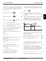
1 . 13
0 . 35
5.0
259
266
5.1
SI EM
E382 E380E 061 01 03 01
EN S
Servo Ventilator 300/300A
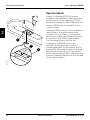
Important
Important
General
Calibration and functional check
Unless stated otherwise, the information
in this Service Manual is valid for:
After any service intervention in Servo
Ventilator 300/300A, perform a
Calibration and Functional check
according to instructions in the
Operating Manual.
Servo Ventilator 300 (SV 300)
Servo Ventilator 300A (SV 300A).
The documentation for the Servo
Ventilator 300/300A consists of:
Operating Manual
Service Manual
Circuit Diagram
Spare Parts Catalogue
Reference Manual, Computer Interface
The Operating Manual is an indispensable complement to the Service Manual
for proper servicing.
In addition to the Important information
given here and in the related documents,
always pay attention to applicable local
and national regulations.
Responsibility for the safe functioning of
the equipment reverts to the owner or
user in all cases in which service or
repair has been done by a nonprofessional or by persons who are not
employed by or authorized by Siemens,
and when the equipment is used for
other than its intended purpose.
Data on internal pressures in the Servo
Ventilator 300/300A are given in Pa (bar).
Airway pressures are given in cm H2O.
1 hPa = 1 mbar
1 kPa = 10 mbar
1 kPa = 0.01 bar
1 kPa i 10 cm H2O
1 kPa i 0.01 at
1 kPa i 0.01 kgf/cm2
1 kPa i 0.01 kp/cm2
1 kPa i 0.145 psi
2
1 mbar = 1 hPa
1 mbar = 0.1 kPa
1 bar = 100 kPa
1 cm H2O i 0.1 kPa
1 at ³ 100 kPa
1 kgf/cm2 i 100 kPa
1 kp/cm2 i 100 kPa
1 psi i 6.9 kPa
Hazard notices
Before disassembling or assembling the
Servo Ventilator 300/300A, make sure
that the:
Gas supply is disconnected.
Mains power cable is disconnected.
Mode selector is set to Ventilator off.
If the mode selector is set in any other
position, the internal battery will
supply power to the PC boards.
The back-up batteries are disconnected when the power section is open.
All gas conveying parts are cleaned
according to instructions in the
Operating Manual.
Service
When working with ESD sensitive
components, always use a grounded
wrist band and a grounded work surface.
Adequate service tools must always be
used.
Some parts in the Servo Ventilator 300/
300A are comprised by a spare parts
exchange system. Your local Siemens
representative supplies factory
calibrated and tested exchange parts as
well as other spare parts indicated in the
spare parts catalogue.
Siemens-Elema AB
E382 E380E 061 01 03 01
Servo Ventilator 300/300A
Important
Important
• The Servo Ventilator 300/300A must be
serviced at regular intervals by specially
trained personnel. The service intervals,
1000 and 3000 operating hours, are
described in the Operating Manual. Any
maintenance must be noted in a log
book provided for that purpose in
accordance with national regulations.
We recommend that service is done as
a part of a service contract with
Siemens.
• A 1000 hour overhaul must be performed
after 1000 hours of operation or, at the
lastest, every six months. In addition,
the ventilator shall undergo a technical
safety check (Function check) twice a
year, at six months intervals or according
to national regulations.
• A 3000 hour overhaul must be performed
after every 3000 hours of operation or,
at the latest, once every year.
• The internal batteries shall be replaced
every 3 years according to instructions in
this Service Manual. The stated battery
back-up time, approx. 30 minutes, can
be guaranteed only if they are used as
power supply back-up at mains failure.
To the responsible service personnel
• The contents of this document are not
binding. If any significant difference is
found between the product and this
document, please contact Siemens for
further information.
• We reserve the right to modify products
without amending this document or
advising the user.
• Only Siemens authorized personnel shall
be permitted to service or repair the
Servo Ventilator 300/300A. Only
Siemens-Elema exchange parts or
genuine spare parts must be used. PC
boards (spare or exchange parts) must
always be kept in a package for sensitive
electronic devices.
• Siemens will not otherwise assume
responsibility for the materials used, the
work performed or any possible
consequences of same.
•
The device complies with the
requirements of the Medical
Device Directive 93/42/EEC.
• The battery on PC 1587 COMPUTER
INTERFACE shall be replaced every 5 years
according to instructions in this Service
Manual.
Pb
• Old non-functioning batteries
and O2 cells must be returned
to the place of purchase or to
a place where they can be
disposed of properly.
Batteries and O2 cells must
not be disposed of with
ordinary waste.
E382 E380E 061 01 03 01
Siemens-Elema AB
3
Servo Ventilator 300/300A
Notes
Notes
4
Siemens-Elema AB
E382 E380E 061 01 03 01
Servo Ventilator 300/300A
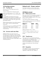
Contents
Contents
7
1
2. Description of functions....................................................... 21
2
3. Disassembling and assembling ......................................... 81
3
4. Service procedures............................................................... 103
4
5. Troubleshooting ..................................................................... 109
5
6. Product change history ........................................................ 113
6
7. Index ........................................................................................ 115
7
8. Diagrams ................................................................................. 121
8
1. Introduction ............................................................................
E382 E380E 061 01 03 01
Siemens-Elema AB
5
Servo Ventilator 300/300A
Notes
Notes
6
Siemens-Elema AB
E382 E380E 061 01 03 01
Servo Ventilator 300/300A
Introduction
1. Introduction
Main units ................................................ 8
Basic principles ........................................ 12
E382 E380E 061 01 03 01
Siemens-Elema AB
7
1
Introduction
Servo Ventilator 300/300A
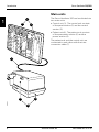
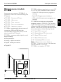
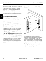
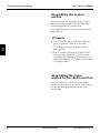
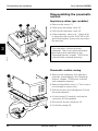
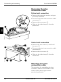
Main units
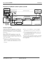
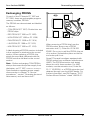
The Servo Ventilator 300 can be divided into
two main units:
1
1
2
• Control unit (1). The control unit consists
of the panel section (2) and the control
section (3).
3
• Patient unit (4). The patient unit consists
of the pneumatic section (5) and the
power section (6).
The patient unit and the control unit are
connected to each other with the interconnection cable (7).
7
6
300-A00X
5
8
4
Siemens-Elema AB
E382 E380E 061 01 03 01
Servo Ventilator 300/300A
Introduction
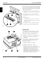
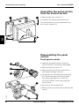
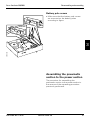
Control unit
The control unit consists of the control
section which is a housing with a number of
PC boards. The panel section, attached to
the control section, is the other part of the
control unit.
With the panel section removed from the
control section, the following parts are
accessible:
• Front panel controls
• PC 1614 PANEL INTERFACE (1) with PC 1588
MICROPROCESSOR MODULE and PAN-PROM
• PC 1745 AUTOMODE PANEL INTERFACE (2). Only
for SV 300A.
2
1
300-A02X
300-A01X
• PC 1617 CONTROL INTERCONNECTION (3).
E382 E380E 061 01 03 01
3
Siemens-Elema AB
9
1
Introduction
Servo Ventilator 300/300A
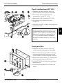
All PC boards in the control section (except
PC 1617 mentioned above) are accessible
when the control section cover is removed.
These PC boards are:
1
• PC 1605 REFERENCE & TIMING (1) with PC
1588 MICROPROCESSOR MODULE and REF-PROM
• PC 1616 INSPIRATORY CONTROL (2) with
PC 1588 MICROPROCESSOR MODULE and MIX-
2
1
PROM
• PC board (3);
– PC 1665 COMPUTER INTERFACE DUMMY or
– Optional PC 1587 COMPUTER INTERFACE (3)
with COM-PROM
• PC 1608 MONITORING (4) with PC 1588
MICROPROCESSOR MODULE and MON-PROM.
4
300-A03X
3
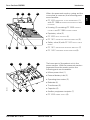
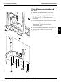
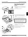
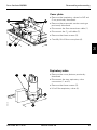
Patient unit
2
1
The upper part of the patient unit is the
pneumatic section. Under the lid of the
pneumatic section you will find the:
• Inspiratory channel (1) including O2 cell
• Expiratory channel (2) including flow
transducer.
The inspiratory valves (gas modules) are
located in three different slots in the
pneumatic section:
• Inspiratory valve unit – AIR (3)
300-A04X
• Inspiratory valve unit – O2 (4)
10
3
4
5
• Inspiratory valve unit – Optional (5).
The valve dummy in the third slot can be
replaced by an inspiratory valve for
administration of e. g. NO gas or by
equipment for nebulizing drugs (Servo
Ultra Nebulizer 345). These products are
described in separate documents.
Siemens-Elema AB
E382 E380E 061 01 03 01
Servo Ventilator 300/300A
Introduction
2
1
3
4
When the pneumatic section casing and the
cover plate is removed, the following parts
are accessible:
1
• PC 1615 EXPIRATORY FLOW LINEARIZATION (1)
with PC 1588 MICROPROCESSOR MODULE and
LIN-PROM
• Housing (2) containing PC 1585 CURRENT
CONTROL and PC 1586 CURRENT POWER
• Expiratory valve (3)
• PC 1622 VALVE CONTROL (4)
• PC 1611 EXPIRATORY PRESSURE AMPLIFIER (5)
300-A05X
• Safety valve (6) with PC 1613 SAFETY VALVE
DRIVER
6
5
7
8
• PC 1611 INSPIRATORY PRESSURE AMPLIFIER (7)
• PC 1607
2
1
4
3
PNEUMATIC INTERCONNECTION (8).
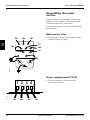
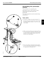
The lower part of the patient unit is the
power section. With the pneumatic section
separated from the power section the
following parts are accessible:
• Mains power inlet (1)
• External battery inlet (2)
• Operating time meter (3)
• Batteries (4)
300-A06X
• Transformer (5)
• Capacitor (6)
5
6
7
8
• Auxiliary equipment outputs (7)
• PC 1618 POWER SUPPLY (8).
E382 E380E 061 01 03 01
Siemens-Elema AB
11
Introduction
Servo Ventilator 300/300A
Basic principles
1
9
11
12
8
10
2
7
1
300-F71X
6
12
5
4
Siemens-Elema AB
3
E382 E380E 061 01 03 01
Servo Ventilator 300/300A
Introduction
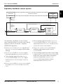
Gas flow through the patient unit
Inspiratory flow
Expiratory flow
1. Gas inlet for air. The connected air must
have a pressure between 200 and 650
kPa (2 and 6.5 bar).
8. The patient system's expiratory gas tube
is connected at the expiratory inlet. The
expiratory inlet also contains a moisture
trap.
2. Gas inlet for O2. The connected O2 must
have a pressure between 200 and 650
kPa (2 and 6.5 bar).
3. The flow of the gas delivered to the
patient system is regulated by the
inspiratory valves. There is one inspiratory valve unit (gas module) for each
gas. The inspiratory valves are regulated
by a feedback control system that is
described in this chapter.
4. The gases are mixed in the inspiratory
mixing part.
5. The pressure of the mixed gas delivered
to the patient (inspiratory pressure) is
measured by the inspiratory pressure
transducer. The transducer is protected
by a bacteria filter.
6. The inspiratory pipe leads the mixed gas
from the inspiratory mixing part to the
patient system. The inspiratory pipe also
contains the safety valve, a holder for the
O2 cell and the inspiratory outlet. The
springloaded safety valve will open in
case of a power failure and/or if the inspiratory pressure exceeds 120 cm H2O. It
will also open if the set upper pressure
limit is exceeded by 5 cm H2O.
9. The gas flow through the expiratory
channel is measured by the expiratory
flow transducer. Patient trigger efforts,
indicated by a decreased continuous
flow, are sensed by this expiratory flow
transducer.
10. The expiratory pressure is measured by
the expiratory pressure transducer. The
transducer is protected by a bacteria
filter. Patient trigger efforts, indicated by
a pressure drop, are sensed by this
expiratory pressure transducer.
11. The pressure of the gas (PEEP pressure)
in the patient system is regulated by the
expiratory valve. The expiratory valve is
regulated by a feedback control system
that is described in this chapter.
12. The gas from the patient system leaves
the ventilator via this expiratory outlet.
The outlet contains a non-return valve
which is a part of the patient triggering
system.
7. The oxygen concentration inside the
inspiratory pipe is measured by the O2
cell. The O2 cell is protected by a
bacteria filter.
E382 E380E 061 01 03 01
Siemens-Elema AB
13
1
Introduction
Servo Ventilator 300/300A
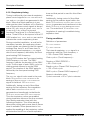
Feedback control system – General
1
CONTROLLING
ELEMENT
CONTROLLED SYSTEM
TRANSDUCER
SIGNAL AMPLIFIER
(WITH SERVO)
COMPARING
ELEMENT
CONTROLLING SYSTEM
ACTUAL
VALUE
P
CONVERTER
I
"COMPENSATOR"
REFERENCE
VARIABLE
ACTUATING
SIGNAL
"ERROR
CALCULATOR"
DESIRED
VALUE
PID-CONTROLLER
300-A08E
Any CONTROLLING SYSTEM may comprise one
single CONTROLLER or, for instance, a cascade
of more than one CONTROLLER. Compensating
elements may also be added.
CONTROLLER symbol used in
this chapter.
In each CONTROLLER, the actual value normally
from a TRANSDUCER in the CONTROLLED SYSTEM is
compared to the desired value = REFERENCE
VARIABLE. The difference between these two
input values results at the output of the
controlling system in an ACTUATING SIGNAL.
Each CONTROLLER may comprise some
combination of the following parts:
• Proportional action, P
• Integral action, I
• Derivative action, D.
14
D
ERROR
SIGNAL
P-action gives a continuous basic positioning.
I-action gives a slowly varying positioning
compensation for small long time deviation.
D-action gives a speed-up positioning
reaction at (fast) changes.
The signals from these parts (from the parts
used in the actual combination) are added.
The sum is the total ERROR SIGNAL which may
be converted before use as an ACTUATING
SIGNAL.
Each CONTROLLING ELEMENT (in the ventilator:
inspiratory valves and expiratory valve) is
positioned by the ACTUATING SIGNAL from its
controlling system. Feedback control, which
is synonymous with regulation, results in the
controlled valve being moved into such a
position that the ACTUAL VALUE is kept equal to
the DESIRED VALUE independently of
disturbance variables like changes in the
airway resistance or lung compliance.
Siemens-Elema AB
E382 E380E 061 01 03 01
Servo Ventilator 300/300A
Introduction
Inspiratory feedback control system
REFERENCE
& TIMING
PRESSURE
FLOW
REF.
MIXER
POSITION VALVE
SENSOR SOLENOID
FLOW
GAS
SUPPLY
PRESS.
GAS
FLOW
ACTUAL
SUPPLY
PRESS.
VALUE
ACTUAL
GAS FLOW
VALUE
GAS
FLOW
REF.
INSPIRATORY
CONTROL
INSPIRATORY
VALVE
CONTROLLED SYSTEM
TRANSDUCERS
INSP. VALVE POSITION
ACTUAL POSITION VALUE
FLOW PI
CONTROL
DESIRED
POSITION
VALUE
DESIRED
GAS FLOW
VALUE
ACTUAL CURRENT VALUE
POSITION PD
CONTROL
DESIRED
CURRENT
VALUE
CURRENT
CONTROL &
CURRENT
POWER
300-A09E
VALVE POSITION
CALCULATOR
Flow
regulation
FLOW CONTROL
The inspiratory feedback control system
uses cascade control with a number of
controllers and compensating elements.
Flow regulation
Inspiratory flow regulation occurs during
inspiration time in the modes Volume
Control and SIMV (Vol. Contr.) and during
expiration time in all modes.
When flow regulation is used, the
shadowed main forward path comprises the
following:
• The microprocessor module in the block
MODE CPU in the main block REFERENCE &
TIMING generates a FLOW REF. signal.
• The block MIXER, in the main block
INSPIRATORY CONTROL, splits the FLOW REF.
signal into one GAS FLOW REF. signal for each
inspiratory valve (AIR FLOW REF. and O2 FLOW
REF.). Each GAS FLOW REF. signal is used
(after a minor correction within ±5 %) as
DESIRED GAS FLOW VALUE (reference variable).
E382 E380E 061 01 03 01
•
is generated by
signal converters (FLOW) using signals from
measuring TRANSDUCERS.
ACTUAL GAS FLOW VALUE
• The actuating signal from the FLOW PI
CONTROL results in the DESIRED POSITION VALUE
(reference variable) for the POSITION PD
CONTROL. The POSITION SENSOR at the
INSPIRATORY VALVE generates a valve position
signal which is used as the ACTUAL POSITION
VALUE in the POSITION PD CONTROL.
• The actuating signal from the POSITION PD
CONTROL results in the DESIRED CURRENT VALUE
(reference variable) for the CURRENT CONTROL
& CURRENT POWER.
• The ACTUAL CURRENT VALUE is an internal
feedback signal used in the CURRENT
CONTROL block.
• The actuating signal from the output stage
of the CURRENT CONTROL & CURRENT POWER is a
voltage pulse train with pulse width
modulation used to actuate the INSPIRATORY
VALVE SOLENOID which generates a certain
opening of the INSPIRATORY VALVE.
Siemens-Elema AB
15
1
Introduction
1
Servo Ventilator 300/300A
In addition to the main forward path,
compensating elements are added as
described in both inspiratory feedback
control system pictures. The compensating
elements in this system works as follows:
• Using the input information of ACTUAL
SUPPLY PRESSURE VALUE and DESIRED GAS FLOW
VALUE the VALVE POSITION CALCULATOR directly
generates a rough approximate POSITION
VALUE which helps to obtain the desired
position within minimum time.
• The input information of ACTUAL SUPPLY
PRESSURE VALUE is used (inverted and
adequatly scaled) to create one small part
of the DESIRED CURRENT VALUE. This small part
of the DESIRED CURRENT VALUE will – in
combination with the opening force of the
INSPIRATORY VALVE implied by the pressure of
the supplied gas – help to balance the
closing force on the INSPIRATORY VALVE
implied by the mechanical spring inside
the VALVE SOLENOID even in closed position
of the INSPIRATORY VALVE.
16
Siemens-Elema AB
E382 E380E 061 01 03 01
Servo Ventilator 300/300A
Introduction
Inspiratory feedback control system (cont'd)
REFERENCE
& TIMING
PRESSURE REF.
TRANSDUCERS
DESIRED PRESS.
VALUE
INSP. PRESSURE
ACTUAL PRESS. VALUE
FLOW
REF.
MIXER
GAS
SUPPLY
PRESS.
GAS
FLOW
ACTUAL
SUPPLY
PRESS.
VALUE
ACTUAL
GAS FLOW
VALUE
Pressure
regulation
INSP. VALVE POSITION
ACTUAL POSITION VALUE
ACTUAL CURRENT VALUE
GAS
FLOW
REF.
INSPIRATORY
CONTROL
300-A10E
POSITION
VALVE
SENSOR SOLENOID
PRESSURE FLOW
PRESS.
PID
CONTR.
1
INSPIRATORY
VALVE
CONTROLLED SYSTEM
POSITION PD
CONTROL
FLOW PI
CONTROL
DESIRED
POSITION
VALUE
DESIRED
GAS FLOW
VALUE
DESIRED
CURRENT
VALUE
CURRENT
CONTROL &
CURRENT
POWER
VALVE POSITION
CALCULATOR
FLOW CONTROL
Pressure regulation
Inspiratory pressure regulation is used only
during inspiration time in all modes except
when flow regulation is used as mentioned
previously.
When PRESSURE regulation is used, the
shadowed main forward path includes the
PRESSURE PID CONTROL block in the REFERENCE &
TIMING main block:
• ACTUAL VALUE is the INSP. PRESSURE signal
from the INSPIRATORY PRESSURE TRANSDUCER
• The actuating signal from the PRESSURE PID
CONTROL block is used as a FLOW REFERENCE
signal going to the MIXER.
The rest of the controlling system, including
compensating elements, is the same as in
flow regulation.
• DESIRED VALUE is the PRESSURE REFERENCE
signal from (the microprocessor module
MODE CPU within) the main block REFERENCE
& TIMING
E382 E380E 061 01 03 01
Siemens-Elema AB
17
Introduction
Servo Ventilator 300/300A
Notes
1
20
Siemens-Elema AB
E382 E380E 061 01 03 01
Servo Ventilator 300/300A
Introduction
Expiratory feedback control system
TRANSDUCER
1
EXPIRATORY
VALVE
CONTROLLED SYSTEM
POSITION VALVE
SENSOR SOLENOID
PRESSURE
EXP.
PRESSURE
EXP. VALVE POSITION
ACTUAL POSITION VALUE
ACTUAL CURRENT VALUE
ACTUAL
EXPIRATORY
PRESSURE
VALUE
300-A11E
PEEP LEVEL
DESIRED EXPIRATORY
PRESSURE VALUE
PEEP PID
CONTROL
POSITION
REF.
POSITION PD
CONTROL
DESIRED
POSITION
VALUE
EXP. VALVE
CURRENT REF.
DESIRED
CURRENT
VALUE
CURRENT
CONTROL
&
CURRENT
POWER
PRESSURE CONTROL
The expiratory feedback control system
uses cascade control. It is active only during
expiration time in all modes. It applies
PRESSURE regulation.
• The actuating signal from the POSITION PD
CONTROL block is the EXP. VALVE CURRENT REF.
signal used as DESIRED VALUE for the CURRENT
CONTROL & CURRENT POWER block.
• DESIRED VALUE is the PEEP LEVEL signal from
the PANEL SECTION (according to front panel
setting)
• The ACTUAL CURRENT VALUE is an internal
feedback signal used in the CURRENT
CONTROL block.
• ACTUAL VALUE is the EXP. PRESSURE signal
from the expiratory PRESSURE TRANSDUCER.
• The actuating signal from the output stage
of the CURRENT CONTROL & CURRENT POWER is a
pulse train with pulse width modulation
used to actuate the EXPIRATORY VALVE
SOLENOID which generates a certain
opening of the EXPIRATORY VALVE.
• The actuating signal from the PEEP PID
CONTROL block is the POSITION REF. signal
used as DESIRED VALUE for the POSITION PD
CONTROL.
• ACTUAL VALUE is the EXP. VALVE POSITION signal
from the POSITION SENSOR in the EXPIRATORY
VALVE.
E382 E380E 061 01 03 01
Siemens-Elema AB
17
19
Introduction
Servo Ventilator 300/300A
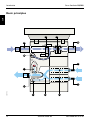
Principle diagram
EXTERNAL
CONTROL
SIGNALS
INPUT FROM
SV 300 INTERNAL
MICROPROCESSORS
EXTERNAL
OUTPUT
SIGNALS
CONTROL UNIT
PATIENT UNIT
FROM
PATIENT
C
CONTROL
SIGNALS
COMPUTER INTERFACE
INPUT SIGNALS
11
M
M
C
P
T
INPUT SIGNALS
MONITORING
10
L
G
EXP.
FLOW
M
PRESSURE
AMPLIFIER
EXP. PRESSURE
PRESSURE
CONTROL
PEEP LEVEL
REFERENCE & TIMING
INSPIRATORY CONTROL
T
I
O2 CONC.
AMPLIFIER
INSP. PRESSURE
PRESSURE
PID CONTROL
FLOW REF.
MIXER
M
VALVE CONTROL V
O2 FLOW REF.
PRESSURE REF.
9
O2 CONC.
EXPIRATORY
VALVE
X
AIR FLOW REF.
SELECTION OF
PRESSURE OR
FLOW REGULATION
Pressure
MODE CPU
Flow
FLOW REF.
1
O2
2
4
TRANSDUCERS
5
O2
CELL
M
FLOW
CONTROL
O2 FLOW REF.
P
TO
PATIENT
INSPIRATORY VALVE UNIT - O2
7
O
AIR
TRANSDUCERS
M
FLOW
CONTROL
3
AIR FLOW REF.
6
H
INSPIRATORY VALVE UNIT - AIR
A
PRESSURE
AMPLIFIER
8
INSP. PRESSURE
M
+5V
300-A12E
±15V
18
+24V
Siemens-Elema AB
W
POWER SUPPLY
12
EXT. BATTERY
MAINS POWER
INTERNAL
BATTERY
E382 E380E 061 01 03 02
Servo Ventilator 300/300A
Introduction
Inspiratory regulation
Monitoring
1. Choice between pressure regulation and
flow regulation during inspiration is
made by the MODE CPU dependent on the
Mode selection.
10. The MONITORING board monitors and
generates certain displayed parameters.
It also activates alarm functions.
2. Main parameters used for the flow level
during inspiration when flow regulation
is used.
Computer interface
3. Main parameters used for the pressure
level during inspiration when pressure
regulation is used.
4. Inspiration rise time setting determines
the initial inspiration pattern. A successively increased flow/pressure level may
be more comfortable for the patient.
5. The O2 concentration delivered to the
patient depends on the setting of these
O2 concentration control knobs.
6. INSPIRATORY VALVE UNIT– AIR.
The control system is described in
section "Inspiratory feedback control
system" in this chapter.
7. INSPIRATORY VALVE UNIT– O2.
The control system is described in
section "Inspiratory feedback control
system" in this chapter.
11. The optional COMPUTER INTERFACE board is
used as input/output signal interface and
includes functions for computer
communication (RS-232). The PC board
is equipped with the following
connectors:
– Master/Slave connection (N80)
– Analog I/O terminal (N81)
– Serial communication ports (N82/N83)
– Analog input & Digital code port (N84).
Power supply
12. The POWER SUPPLY board controls and
distributes power to the different parts
of the ventilator. The power source can
be:
– Mains power
– External battery
– Internal battery.
Expiratory regulation
8. PEEP level setting is used as DESIRED
EXPIRATORY PRESSURE VALUE. See section
"Expiratory feedback control system" in
this chapter.
9. EXPIRATORY VALVE interacts with the VALVE
CONTROL board as described in section
"Expiratory feedback control system" in
this chapter.
E382 E380E 061 01 03 01
Siemens-Elema AB
19
21
1
Introduction
Servo Ventilator 300/300A
Notes
1
20
Siemens-Elema AB
E382 E380E 061 01 03 01
Servo Ventilator 300/300A
Description of functions
2. Description of functions
General .................................................... 22
Microprocessor module PC 1588 ............ 23
Version labels .......................................... 24
Control unit – Panel section ..................... 25
1
Front panel ....................................... 25
1A Automode front panel ...................... 27
2
Panel interface .................................. 28
2A Automode panel interface ................ 29
Control unit – Control section .................. 30
3
Computer interface .......................... 30
3A Computer interface dummy ............. 33
4
Monitoring ........................................ 34
5
Optional PC board slot ...................... 48
6
Reference & Timing ......................... 49
7
Inspiratory control ............................. 61
Patient unit – Pneumatic section ............. 62
8
Inspiratory valve unit – Air ................ 62
9
Inspiratory valve unit – O2 . ............... 67
10 Inspiratory valve unit – Optional ....... 67
11 Inspiratory channel ........................... 68
12 Inspiratory pressure .......................... 70
13 Expiratory pressure .......................... 71
14 Expiratory channel ............................ 71
15 Valve control ..................................... 73
16 Expiratory valve ................................ 74
17 Optional interface ............................. 74
18 Expiratory flow linearization .............. 75
19 Cooling system ................................ 76
Patient unit – Power section .................... 76
20 Mains power .................................... 76
21 Power supply ................................... 77
22 Operating power .............................. 79
23 Interconnection cable ....................... 80
E382 E380E 061 01 03 01
Siemens-Elema AB
21
2
Description of functions
Servo Ventilator 300/300A
General
As described in chapter Introduction, the
Servo Ventilator 300 can be divided into two
Main units; Control unit and Patient unit. The
two main units are connected to each other
with the Interconnection cable.
2
For the purpose to describe all different
functions in the Servo Ventilator 300, the
two main units are further divided as
follows:
In this Description of functions, the words
inspiratory and expiratory are used in the
first place to indicate the site of a part (e g
INSPIRATORY CHANNEL).
The words inspiration and expiration are
used in the first place to indicate the
corresponding time interval during
ventilation (e g INSPIRATION TIME)
Main unit
Section
Main block
Functional block
Example:
Control unit
Panel section
1 Front panel
1.1 Patient range selection
1.2 Airway pressure
etc.
2 Panel interface
2.1 Panel CPU including PAN-PROM
functions
2.2 Parameter buffers
etc.
Functional descriptions of the Main blocks
and Functional blocks can be found in this
chapter. This functional description is based
on and refers to the Functional block diagram
that can be found as a fold out on the rear
cover.
22
Siemens-Elema AB
E382 E380E 061 01 03 01
Servo Ventilator 300/300A
Description of functions
Microprocessor module
PC 1588
PC 1588 includes a green/red WATCHDOG LED
D1 (3). The LED indications are as follows:
A MICROPROCESSOR MODULE, PC1588 (1), is
included on each one of the following five
PC boards:
– Green LED: Microprocessor program is
running.
• PC 1605 – REFERENCE & TIMING
– LED not lit: Microprocessor program not
running.
• PC 1608 – MONITORING
• PC 1614 – PANEL INTERFACE
• PC 1615 – EXP. FLOW LINEARIZATION
• PC 1616 – INSPIRATORY CONTROL.
PC 1588 is mounted with its two rows of
connectors (P65 and P66) into the
corresponding connectors (HYB1) on the
above mentioned PC boards.
PC 1588 is a programmable digital control
block including:
• Microprocessor
– Red LED: Program error indication.
PC 1588 also includes an exchangable
program memory, PROM (2). The function
of PC 1588 depends on this PROM which is
different on the five different enumerated
boards. The PROM functions are mentioned
in the description of the following blocks:
• 2.1 Panel CPU (PAN-PROM)
• 4.1 Monitor/Alarm CPU (MON-PROM)
• 6.1 Mode CPU (REF-PROM)
• 7.1 Mixer CPU (MIX-PROM)
• 18.1 Linearizing CPU (LIN-PROM)
• Analog – digital conversion
Note – The MICROPROCESSOR -block on
PC 1587 – COMPUTER INTERFACE, includes two
PROM modules (COM-PROM).
PC 1588 is not used on PC 1587.
• Digital – analog conversion
• Digital I/O.
xxx
xxx
300-A13X
1
E382 E380E 061 01 03 01
3
2
Siemens-Elema AB
23
2
Description of functions
Servo Ventilator 300/300A
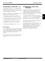
Version labels
A label (1) showing all PROM-versions
included in the ventilator is attached to the
control section. When replacing a PROM,
attach the new label (2) that is delivered with
the new PROM onto the old label on the
control section.
2
1
SV
E
13
XX
XX
XX
08 0X
16 V6. E
PC OM 380
P- R X E
N X
MO XX X
XX
2
300-A14X
Op
e
ra
N
O
SI al
R anu
VE ting M
X
E3
8.x
0
30
3
Changing PROM-versions in the ventilator is
used to add or change functions in the
ventilator. For that reason, it may also be
necessary to replace the Operating Manual
in connection with PROM replacements.
The Operating Manual, valid for the
combination of PROMs used in the
ventilator, is identified with a version
number stated both on the manual and on
the label (3). When replacing the Operating
Manual with a new version of the manual,
attach the new label (3) that is delivered with
the new Operating Manual onto the old label
on the control section.
24
Siemens-Elema AB
E382 E380E 061 01 03 01
Servo Ventilator 300/300A
Description of functions
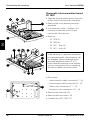
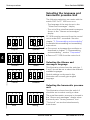
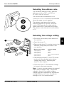
Control unit – Panel section
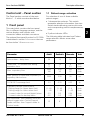
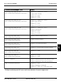
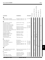
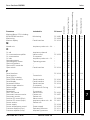
1.1 Patient range selection
The Panel section consists of the main
blocks 1 – 2 which are described below.
For selection of one of three available
patient ranges:
1 Front panel
• 1 three-position selector. This switch
generates selection information from two
switch decks delivering one two bit code
and corresponding two bit complementary
code.
This main block contains the front panel
film, in different language versions, and the
various displays and controls with
connection cables and their connectors.
The optional front panel function for SV 300A
is described in section 1A AUTOMODE that can
be found after 1.8 MODE SELECTION.
Parameter
2
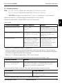
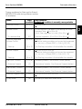
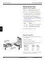
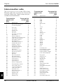
• 3 yellow indicator LEDs.
The following table indicates how Patient
range selection affects some other
parameters:
Adult
Pediatric
Neonate
Unit
Apnea alarm – delay time
20
15
10
s
”Bias flow” = Constant flow during
expiration time
32
2
16
1
8
0.5
ml/s
l/min
Max. inspiratory flow
3000
180
500
30
200
12
ml/s
l/min
Max. (preset or measured) inspiratory or
expiratory tidal volume
3999
399
39
ml
3.3
0.55
0.22
l/s
0 - 60
* - 40
0.3
0.2
0 - 60
* - 40
0.3
0.2
0-6
* - 40
0.06
0.05
l/min
l/min
l/min
l/min
12
8
5
s
FLOW REF overrange limit
Expiratory minute volume alarm:
Setting range for Upper alarm limit
Setting range for Lower alarm limit
* Lowest value for normal (digital) alarm
* Lowest value for backup alarm
For Automode: Time duration since last
patient trigger when Control/Support
mode switches from Support mode to
Control mode.
E382 E380E 061 01 03 01
Siemens-Elema AB
25
Description of functions
Servo Ventilator 300/300A
1.2 Airway pressure
1.3 Respiratory pattern
PRESSURE
For control and monitoring of AIRWAY
parameters:
For control and/or monitoring of respiratory
pattern parameters:
• 4 four-character LED displays.
• 4 four-character LED displays
• 1 double column LED bargraph.
• 5 potentiometer knobs:
• 5 potentiometer knobs:
2
– Upper press. limit. Push button release
function for one-way mechanical stops
at approx. 60, 80 and 100 cm H2O.
– Pressure Control Level above PEEP.
Push button release function for oneway mechanical stops at approx. 30, 60
and 80 cm H2O.
– Pressure Support Level above PEEP.
Push button release function for oneway mechanical stops at approx. 30, 60
and 80 cm H2O.
– PEEP. Push button release function for
one-way mechanical stop at approx.
20 cm H2O.
– Trigg. sensitivity Level below PEEP.
– CMV freq. b/min. This control is
equipped with two parallell
potentiometers – one for the control
function and the other for the monitor/
alarm function.
– Insp. time %. Push button release
function for two-way mechanical stops
at approx. 20, 50 and 70%.
– Pause time %. Push button release
function for one-way mechanical stop at
approx. 20%.
– Insp. rise time %. Push button release
function for one-way mechanical stop at
approx. 1%.
– SIMV freq. b/min.
• 5 yellow indicator LEDs.
• 5 yellow indicator LEDs.
1.4 Volume
For control and/or monitoring of minute
volume and tidal volume parameters:
• 2 four-character green LED displays.
Showing information generated via
2.1 PANEL CPU.
• 3 four-character red LED displays.
Showing information generated via 4.1
MONITOR/ALARM CPU.
• 2 fields of double column LED bargraph.
• 3 potentiometer knobs:
– Volume
– Upper alarm limit
– Lower alarm limit.
• 3 yellow indicator LEDs.
26
Siemens-Elema AB
E382 E380E 061 01 03 01
Servo Ventilator 300/300A
Description of functions
1.5 O2 concentration
1.8 Mode selection
For control and monitoring of O2
concentration parameters:
For the selection of Ventilation Modes and
control of the Set Parameter Guide
functions:
• 1 four-character LED display. Showing
information generated via 2.1 PANEL CPU.
• 1 green Mains indicator LED
• 1 potentiometer knob with push button
release function for two-way mechanical
stop at approx. 60 %. This control is
equipped with two parallell potentiometers
– one for the regulation function and the
other for the monitor/alarm function.
• 1 ten-position selector always supplied
with high impedance 24 V. This switch
generates selection information from two
switch decks delivering complementary
code via PC board (PC 1632). The mode
Optional can not be selected.
• 1 non-locking, two-way selector for
Oxygen breaths and for Start breath.
• 10 different fields each comprising:
– 1 yellow indicator LED
• 2 yellow indicator LEDs.
– 1 touch sensor.
1.6 Alarms and messages
1A Automode front panel
For the display of alarms and messages:
For the control and monitoring of the
Automode functions:
• 1 eight-character LED display. Showing
information generated via 4.1 MONITOR/
ALARM CPU.
• 1 two-position selector for turning the
Automode On and Off
• 8 different alarm fields each comprising:
• 2 yellow indicator LEDs.
– 1 red indicator LED
– 1 yellow indicator LED
– 1 touch sensor
• 1 non-locking, two-way selector for Reset
and for 2 min off. This information is
handled by the main block 4 MONITORING.
1.7 Pause hold
For the control, via main block 6
TIMING, of pause hold functions:
REFERENCE
&
• 1 non-locking two-way selector for Insp.
pause hold and for Exp. pause hold.
E382 E380E 061 01 03 01
Siemens-Elema AB
27
2
Description of functions
2
Servo Ventilator 300/300A
2 Panel interface
2.3 Inputs
This main block consists of the board
PC 1614 PANEL INTERFACE including its
PC1588 MICROPROCESSOR MODULE . The board
is connected (via N18, N19 and N40) to the
mother board (PC 1617) CONTROL INTERCONNECTION and it has connectors (P81 – P99) for
the connection of FRONT PANEL controls.
Analog multiplexor for input signals to the
block 2.1 PANEL CPU.
The FRONT PANEL touch sensors as well as
displays and indicator LEDs are integrated
parts of this board. Refer to 1 FRONT PANEL in
this chapter.
A connector, N20 (on some older PC-boards,
the connector is marked N80), is provided
on the board for additional function. This
connector can be used to connect the
optional PC 1745 AUTOMODE PANEL INTERFACE
used in SV 300A. This function is described
in section 2A AUTOMODE PANEL INTERFACE that
can be found after 2.9 MONITOR DISPLAY.
.
2.1 Panel CPU including PANPROM functions
This block includes the board PC 1588 with
a PAN-PROM. Some details of the PC 1588 are
mentioned in section Microprocessor
module PC 1588 in this chapter.
The PAN-PROM function includes the handling
of input signals from the main block 1 FRONT
PANEL, calculation of some displayed values
and handling of signals to the displays on
the main block 1 FRONT PANEL.
2.2 Parameter buffers
2.4 LED matrix
Time multiplexed addressing and driving
stages for the block 2.5 LED ARRAY. The input
data is given from the block 2.1 PANEL CPU.
2.5 LED array
This block contains the light emitting diodes
of the front panel bargraphs and the yellow
light emitting diodes at the front panel
settings.
Some flashing function in front panel
bargraphs are mentioned in 4.1 MONITOR/
ALARM CPU
2.6 Panel display
This block contains all the green alphanumerical four character light emitting diode
displays on the front panel. The input data is
given from the block 2.1 PANEL CPU.
2.7 Mode select
Input stage for the signals from the front
panel Mode selector. The input is available
as four bit code and corresponding four bit
complementary code generated via the
small interconnecting circuit board PC 1632
on the Mode selector. This block gives the
data to the block 2.1 PANEL CPU.
Input stage for potentiometers on the main
block 1 FRONT PANEL.
28
Siemens-Elema AB
E382 E380E 061 01 03 01
Servo Ventilator 300/300A
Description of functions
2.8 Opto switch
Time multiplexed driving stage and sensor
receiving stage for all the infra-red sensor
touch pads on the front panel. The function
is controlled by the block 2.1 PANEL CPU
including an automatic adaption of the touch
pad sensitivity to the ambient light level.
This block gives the data to the block 2.1
PANEL CPU.
2A Automode panel
interface
The board PC 1745 AUTOMODE PANEL INTERFACE
contains electronics for handling of the
Automode switch.
The status of the switch is given to the
blocks 2.1 PANEL CPU, 5 MONITORING and
6 REFERENCE & TIMING. The LEDs are driven
from the main block 4 MONITORING.
2
2.9 Monitor display
This block contains all the red alphanumerical four character light emitting diode
displays as well as eight yellow and eight
red alarm indicating light emitting diodes
below the Alarms and messages display on
the front panel. This block is driven directly
from the main block 4 MONITORING.
E382 E380E 061 01 03 01
Siemens-Elema AB
29
Description of functions
Servo Ventilator 300/300A
Control unit – Control section
The Control section consists of the main
blocks 3 – 7 which are described below.
There are five connectors (N80 – N84) on
PC 1587.
A ”mother” board, PC 1617 CONTROL
provides signal connections
via connectors (but no electronic functions).
INTERCONNECTION,
2
3 Computer interface
The ventilator can be equipped with the
board PC 1587 COMPUTER INTERFACE to provide
the interface functions described below.
N80
If these interface functions are not needed,
the board PC 1665 COMPUTER INTERFACE DUMMY
can be mounted instead of PC 1587.
The PC 1665-function is described in section
3A COMPUTER INTERFACE DUMMY that can be
found after section 3.9 LED INDICATORS.
N82
N81
N83
N84
The board PC 1587 COMPUTER INTERFACE was
replaced during the mandatory upgrades:
– SV 300, Upgrade 1995-09 (US market)
– SV 300, Upgrade 1995-10 (Rest of World)
As the board PC 1587D was included in
these mandatory upgrades, all SV 300/300A
must be equipped with PC 1587D (or higher).
The main block COMPUTER INTERFACE consists
of the board PC 1587 COMPUTER INTERFACE
which includes one microprocessor and a
COM-PROM. The COM-PROM is divided in two
PROM modules
30
300-A15X
Only accessories, supplies or auxiliary
equipment listed in Siemens-Elema catalogs
(”Products and accessories” Order No.
90 34 562 E323E and ”Spare and exchange
parts” Order No. 90 34 570 E323E) must be
connected to or used in conjunction with the
ventilator.
Warning: Use of accessories and auxiliary
equipment other than those specified in
these catalogs may degrade safety and
performance of the ventilator.
Siemens-Elema AB
E382 E380E 061 01 03 01
Servo Ventilator 300/300A
Description of functions
3.1 Microprocessor CPU
including COM-PROM functions
This includes functions for computer
communication (RS-232) via 3.7 SERIAL
COMMUNICATION PORTS as described in the
Reference Manual "Servo Ventilator 300/
300A, Computer Interface (Firmware version
2.X)", Order No. 63 14 061.
This block also contains a real time clock
with battery backup, driven by a quartz
crystal of 32768 Hz. The purpose of this
clock is to time stamp the trend values
stored in the ventilator. There is also a
possibility to read the actual time through
the RS-232 communication.
3.2 I/O buffers
Analog and digital input and output stages
for the main block 3 COMPUTER INTERFACE.
The voltage level in the battery circuit is
monitored resulting in an error indication on
LED D3 (see 3.9 LED indicators) if the
voltage level is below 3.6 V or above 4.5 V.
An information message is also displayed on
Servo Screen 390 if such unit is connected
to the SV 300.
Note – The voltage level measured in the
battery circuit is higher than the voltage level
in the battery itself.
3.5 Master/Slave connection
15 pole D-sub connector (N80). Can be used
for the synchronization of two Servo
Ventilator 300. Only Siemens connection
cable must be used.
Pin configuration and signal names can be
found in chapter "8. Diagrams".
3.6 Analog I/O terminal
3.3 A/D, D/A
Analog to digital and digital to analog
conversion in connection with the block
3.1 MICROPROCESSOR CPU.
3.4 Battery
On board mounted Lithium battery (3.5 V).
The battery backs up the trend data memory
and the real time clock in the block
3.1 MICROPROCESSOR CPU when the SV 300 is
switched off.
62 pole D-sub connector (N81). Can be used
for connection of monitoring/recording
equipment.
Input control signals can be connected at
N81 to control some ventilator functions
(e.g. when using Bi-Phasic Ventilation).
These input signals are routed via two
sockets, J2 and J3, on PC 1587.
To enable the control functions, jumpers
must be mounted in the sockets.
Pin configuration, signal names and jumpers
can be found in chapter "8. Diagrams".
Normal service interval for exchange of the
battery is approx. 5 years. Replacement of
the battery is described in chapter
”4. Service procedures”.
E382 E380E 061 01 03 01
Siemens-Elema AB
31
2
Description of functions
3.7 Serial communication ports
3.9 LED indicators
26 pole D-sub connectors (N82 and N83) for
RS-232-C data communication. For communication protocol, see Reference Manual
"Servo Ventilator 300/300A, Computer
Interface (Firmware version 2.X)", Order No.
63 14 061 E380E.
There are 9 green/red LED INDICATORS
mounted on PC 1587. The LEDs are visible
if the control section cover is removed.
D9
D1
The connectors are identical with one
exception; the internal clock can only be set
via N82.
Serial communication is indicated on the
LEDs D6 – D9. See 3.9 LED INDICATORS.
Pin configuration and signal names can be
found in chapter "8. Diagrams".
3.8 Analog input & Digital code
port
44 pole D-sub connector (N84). Optional
input interface.
Pin configuration and signal names can be
found in chapter "8. Diagrams".
300-L24X
2
Servo Ventilator 300/300A
LED functions
D1: WATCHDOG. During startup the LED will
flash for a short moment and then be lit red
for a short moment. It will then be lit green
again.
When the startup test is completed, the
LED indications are as follows:
– Green LED: Microprocessor program is
running.
– Red LED: Program error indication.
– LED not lit: Microprocessor program not
running.
32
Siemens-Elema AB
E382 E380E 061 01 03 01
Servo Ventilator 300/300A
Description of functions
D2 – D5: TEST STATUS LED. Error indications
during System startup test. The startup test
is divided in several sequences.
The first sequence is a LED test that starts
with all LEDs red. The LEDs will then
change to green, one at the time (starting
with D2), until all four LEDs are green.
In the hardware test sequence, D3 can be of
special interest for troubleshooting.
In the first phase of the hardware test, D3 is
lit red for a few seconds indicating COM-PROM
error. In the second phase of the hardware
test, D3 is lit red for a few seconds
indicating BATTERY error.
3A Computer interface
dummy
The PC 1665 COMPUTER INTERFACE DUMMY is
mounted instead of PC 1587 COMPUTER
INTERFACE, in the case that there is no need
for serial communication with the ventilator.
It is needed as a holder for the PC 1608, as
well as for disabling the error signal from the
COMPUTER INTERFACE board and the signals for
Master – Slave.
The hardware test sequence ends showing
all LEDs green if no error was detected and
all LEDs red if any error was detected.
Note – As COM-PROM and BATTERY are the only
spare parts for PC 1587, any other LED error
indications than mentioned above results in
a PC 1587 replacement.
D6 – D7: SERIAL INTERFACE 1. Rapidly flashing
green and red indicates communication on
connector N82. D6 indicates input and D7
indicates output.
D8 – D9: SERIAL INTERFACE 1. Rapidly flashing
green and red indicates communication on
connector N83. D8 indicates input and D9
indicates output.
E382 E380E 061 01 03 01
Siemens-Elema AB
33
2
Description of functions
Servo Ventilator 300/300A
4 Monitoring
This main block consists of the board
PC 1608 MONITORING including its PC 1588
MICROPROCESSOR MODULE and the
4.7 LOUDSPEAKER.
New versions of PC 1608 MONITORING and
was introduced in production
during 1996 and also as an optional upgrade
on delivered units. The upgrade was called
”SV 300, ALARM SYSTEM ENHANCEMENT KIT 96-05”.
The new versions was:
MON-PROM
2
MON-PROM
This block includes the board PC 1588 with
a MON-PROM. Some details of the PC 1588
are mentioned in section Microprocessor
module PC 1588 in this chapter. The MONPROM functions include the (program control)
digital monitoring of certain parameters and
the activation of alarm functions:
• Front panel indications via the block
2.9 MONITOR DISPLAY
• Audible indications via the block
4.3 SOUND & ALARM CONTROL.
– PC 1608E
–
4.1 Monitor/Alarm CPU including
MON-PROM functions
V6.00
As the upgrade was optional and not
mandatory, a number of not upgraded
SV 300 are equipped with MON-PROM V5.01
(and PC 1608A, -B, -C or -D). These units
must be equipped with a FAILURE ALARM BOX.
Note – PC 1608E is backwards compatible
and can be equipped with MON-PROM V5.01.
The FAILURE ALARM BOX must be used also on
these units.
The alarm functions of the FAILURE ALARM BOX
are integrated on MON-PROM V6.00/PC 1608E
and the FAILURE ALARM BOX is not used on
SV 300 equipped with MON-PROM V6.00/
PC 1608E (or higher).
In the following description (4.1.1 – 4.1.8)
alarms are mentioned in groups, each group
associated with corresponding Alarm field
within the Front panel field ”Alarms and
Messages”.
For each Alarm field this description of the
normal (digital control) alarm contains:
• Alarms and Messages - Alarm field
name
• Parameter monitored for alarm, PMA
and corresponding Reference value
• Alarm table
containing conditions for alarm.
For more information about PROM, PC board
and Operating Manual versions, see chapter
”6. Product change history”.
34
Siemens-Elema AB
E382 E380E 061 01 03 01
Servo Ventilator 300/300A
Description of functions
4.1.1 Airway pressure
PMA:
PI =
INSP. PRESSURE;
signal from main block 12
INSPIRATORY PRESSURE.
PE =
EXP. PRESSURE;
signal from main block 13
EXPIRATORY PRESSURE.
LIM_PRESS.L = Signal from the block 6.1
MODE CPU
including
REF-PROM
functions.
Reference value Pmax = Preset Upper pressure limit (on Front panel).
Reference value PEEP = Preset PEEP Level (on Front panel).
2
Alarm table:
1
2
3
”Alarms and messages”
Alarm condition
Remark
Airway pressure too high
PI > Pmax or
PE > Pmax
At true condition 1
INSPIRATION is inhibited
and EXPIRATION is started.
2
High continuous pressure
PI > PEEP + 15 cm H2O or Alarm if any of the
conditions remains true
PE > PEEP + 15 cm H2O
during 15 s.
Limited pressure
LIM_PRESS.L = active,
(corresponds to condition:
PREF = Pmax – 5 cm H2O
and resulting Tidal/Minute
volume ventilation is less
than front panel setting)
LIM_PRESS.L signal 3 only
used during PRVC or VS
mode. Alarm if the
mentioned alarm condition
is true during three
consecutive breaths.
Refer to 6.1.2 Respiratory timing - condition (3).
Identical condition is also monitored separately within the main block 2. Panel interface
and that is used for the following function: At true condition the Airway pressure bargraph
indication for Upper pressure limit is flashing.
Refer to 6.1.1 Reference generation - PRVC and VS mode.
Monitoring also controls the following opening and closing of the Safety valve:
Opening condition
Remark
PI > Pmax + 6 cm H2O or
PE > Pmax + 6 cm H2O
The Safety valve opens. If the opening was caused by
any of these conditions the Backup alarm system
generates continuous audible alarm.
When opened the Safety valve will stay open until following conditions are true:
Precondition
Closing condition
Safety valve stays open at least during
400 ms.
PI < Pmax + 5 cm H2O and
PE < Pmax + 5 cm H2O
For Airway pressure alarm also see 4.5 Backup alarm system.
E382 E380E 061 01 03 01
Siemens-Elema AB
35
Description of functions
Servo Ventilator 300/300A
4.1.2 O2 concentration
PMA:
O2 concentration = Signal generated within the block 4.1 using O2 CONC. signal from
the block 11.3 O2 CELL which is digitally compensated for mean airway pressure and
barometric pressure according to BAROMETER PRESSURE signal from 4.6 BAROMETER
PRESSURE TRANSDUCER.
Reference value Set O2 = Preset O2 concentration (on Front panel).
2
Alarm table:
”Alarms and messages” text
Precondition
Alarm condition
O2 conc too high
21% < Set O2 < 100%
PMA > Set O2 + 6%
O2 conc too low
21% < Set O2 < 24%
24% < Set O2 < 96%
96% < Set O2
PMA < 18%
PMA < Set O2 – 6%
PMA < 90%
”Alarms and messages” text
Additional function
O2 SENSOR
If the O2 cell is disconnected; High priority alarm
that can be changed to a caution signal.
If above mentioned O2 concentration alarm condition is true during less than 55 s the alarm
is not registered in the alarm memory.
If the O2 concentration setting is changed more than 2 percentage units, the alarm is
automatically muted for maximum 55 s. This also applies at activation of ”Oxygen breath”.
For O2 concentration alarm also see 4.5 Backup alarm system.
4.1.3 Optional alarm field
On earlier versions of the ventilator, the alarm field name was ”CO2 concentration”.
This optional alarm field is not used.
36
Siemens-Elema AB
E382 E380E 061 01 03 01
Servo Ventilator 300/300A
Description of functions
4.1.4 Exp. minute volume
PMA:
Exp. min. vol. = signal from the block 4.4
FLOW FILTERS
&
INTEGRATORS.
Reference value Mmax = Preset Upper alarm limit for Expired minute volume
Reference value Mmin = {The highest of the following two possibilities:}
= Preset Lower alarm limit for Expired minute volume or
= Lowest value for normal (digital) alarm; value according to table in 1.1. Patient range
selection.
2
Alarm table:
”Alarms and messages” text
Alarm condition
Exp. minute volume too high
PMA > Mmax
1
Exp. minute volume too low
PMA < Mmin
2
1
Identical condition is also monitored separately within the main block 2 PANEL INTERFACE and
that is used for the following function: At true condition the Minute volume bargraph
indication for Upper alarm limit is flashing.
2
Identical condition is also monitored separately within main the block 2 PANEL INTERFACE and
that is used for the following function: At true condition the Airway pressure bargraph
indication for Lower alarm limit is flashing.
For Exp. minute volume alarm also see 4.5 BACKUP ALARM SYSTEM.
4.1.5 Apnea
PMA:
The measured time durations TC corresponding to Breath cycle.
TC = Time duration measured from each Start Inspiration until next Start Inspiration.
Reference value Td = {Apnea alarm delay time}, Value according to table in block 1.1 PATIENT
RANGE SELECTION.
Alarm table:
”Alarms and messages” text
Alarm condition
Remark
APNEA ALARM
TC > Td
Activated alarm stays active
until reset on Front panel.
If the Mode selector is in position VS and Apnea alarm is active the ventilator performs
PRVC Mode. See 6.1.2. RESPIRATORY TIMING ”condition (A)”.
E382 E380E 061 01 03 01
Siemens-Elema AB
37
Description of functions
Servo Ventilator 300/300A
4.1.6 Gas supply
PMA:
Measured gas supply pressures
PAIR = Air supply pressure
PO2 = Oxygen supply pressure
Alarm table:
2
”Alarms and messages” text
Alarm condition
Air supply pressure too high Air: X.X bar O2: X.X bar
PAIR > 6.5 bar
O2 supply pressure too high Air: X.X bar O2: X.X bar
PO2 > 6.5 bar
Air supply pressure too low Air: X.X bar O2: X.X bar
PAIR < 2.0 bar 1 & 3 & 4
O2 supply pressure too low Air: X.X bar O2: X.X bar
PO2 < 2.0 bar 2 & 3 & 4
1
The high priority alarm may be downgraded to a silent caution alarm if the set O2 concentration is between 98 and 100%.
2
The high priority alarm may be downgraded to a silent caution alarm if the set O2 concentration is between 21 and 23%.
3
In case of PAIR or PO2 < 1.0 bar, the inspiratory flow is compensated for the missing flow by
the remaining gas.
4
In case of gas failure of both gases, the safety valve and the expiratory valve will open. The
alarm in this case:
”Alarms and messages” text
Alarm condition
Air supply pressure too low O2 supply pressure too low
Air: X.X bar O2: X.X bar
PAIR < 2.0 bar and
PO2 < 2.0 bar
38
Siemens-Elema AB
E382 E380E 061 01 03 01
Servo Ventilator 300/300A
Description of functions
4.1.7 Battery
PMA:
Measured voltage levels. External power voltage level: The block 21.3 VOLTAGE
CONTROL & TIMING indicates, by the INTERNAL BATTERY MODE signal, in case the external
main and external battery power voltages are both too low.
Ubat =
INTERNAL BATTERY VOLTAGE;
signal from the block 21.5
BATTERY CHARGE CONTROL.
”Alarms and messages” text
Precondition
BATTERY
INTERNAL BATTERY MODE
= active (during > 3.5 s)
Note: This message is shown flashing.
2
Alarm table:
”Alarms and messages” text
Condition
Internal battery voltage too high Internal: X.X V
Ubat > 33.5 V
Limited battery capacity left Internal: X.X V
21 V < Ubat < 23 V
No battery capacity left SEE OPERATING MANUAL
19.5 V < Ubat < 21 V
Further condition
Remark
Ubat < 19.5 V
No power supply is distributed to the ventilator valves.
E382 E380E 061 01 03 01
Siemens-Elema AB
39
Description of functions
Servo Ventilator 300/300A
4.1.8 Technical
PMA 1: Start up test results. Signals generated within the main block 4. MONITORING. The start
uptest is made once each time the Mode selector is turned from the position Off.
The start up test comprises the following parts:
– Power Failure Monitor hardware test. Concerns the function of the hardware
which is used as Power Failure Monitor for upper and lower alarm limits for
internal Supply Voltages. The function of this Power Failure Monitor hardware is to
constitute Alarm limit values for the different supply voltages as shown in Supply
voltage, Alarm table in 4.5 BACKUP ALARM SYSTEM. The status of the backup capacitor
for this hardware is also checked (the capacitor is also checked regularly during
operation).
2
– Internal RAM test; concerns the RAM within the block 4.1 MONITOR/ALARM CPU
– Internal ROM test; concerns the MON-PROM within the block 4.1 MONITOR/ALARM CPU
– Internal CPU test; concerns the CPU within the block 4.1 MONITOR/ALARM CPU
Alarm Table:
”Alarms and messages” text
PMA 1: Alarm condition
Error indication from:
Technical error code PFT RESTART
Power failure test
Technical error code RAM RESTART
Internal RAM test
Technical error code ROM RESTART
Internal ROM test
Technical error code CPU RESTART
Internal CPU test
40
Siemens-Elema AB
E382 E380E 061 01 03 01
Servo Ventilator 300/300A
Description of functions
PMA 2: Microprocessor failure. Signals from each of the following blocks:
2.1 PANEL CPU (PC 1614 PANEL INTERFACE)
3.1 MICROPROCESSOR CPU (PC 1587 COMPUTER INTERFACE)
6.1 MODE CPU (PC 1605 REFERENCE & TIMING)
7.1 MIXER CPU (PC 1616 INSPIRATORY CONTROL)
18.1 LINEARIZING CPU (PC 1615 EXP. FLOW LIN.)
2
Alarm table:
”Alarms and messages” text
PMA 2: Alarm condition
Microprocessor failure
signal (repeatedly) from:
Technical error code µP Pan SEE OPERATING MANUAL/
RESTART
Panel interface
Technical error code µP SCM SEE OPERATING MANUAL/
RESTART
Computer interface
Technical error code µP R&T SEE OPERATING MANUAL/
RESTART
Reference & Timing
Technical error code µP Mix SEE OPERATING MANUAL/
RESTART
Inspiratory control
Technical error code µP Exp SEE OPERATING MANUAL/
RESTART
Exp. flow lin.
E382 E380E 061 01 03 01
Siemens-Elema AB
41
Description of functions
Servo Ventilator 300/300A
PMA 3: Monitored front panel inputs. Signals from each of the following blocks:
1.1 PATIENT RANGE SELECTION (from Patient range selector)
1.3 RESPIRATORY PATTERN (from CMV freq. setting - double potentiometer)
1.5 O2 CONCENTRATION (from O2 concentration setting - double potentiometer)
1.8 MODE SELECTION (from Mode selector via 2.8 Mode select - Input stage)
2
Alarm table:
”Alarms and messages” text
PMA 3: Alarm condition
Certain difference
exceeded (repeatedly) between the two Front panel
inputs coming in pair from:
Technical error code SwR SEE OPERATING MANUAL
Patient range switch
Technical error code SwM SEE OPERATING MANUAL
Mode selector
Technical error code PoC SEE OPERATING MANUAL
CMV frequency setting
Technical error code PoO SEE OPERATING MANUAL
O2 concentration setting
PMA 4: PB. Barometer pressure (signal from 4.6 BAROMETER PRESSURE TRANSDUCER)
Alarm table:
”Alarms and messages” text
PMA 4: Alarm condition
Technical error code Ba SEE OPERATING MANUAL
PB < 700 mbar or
PB > 1100 mbar
42
Siemens-Elema AB
E382 E380E 061 01 03 01
Servo Ventilator 300/300A
Description of functions
PMA 5: Internal supply voltages. Failure signal from Power Failure Monitor hardware (part of the
block 4.5 BACKUP ALARM SYSTEM).
Reference values (alarm limits) according to 4.5 BACKUP ALARM SYSTEM.
Alarm table:
”Alarms and messages” text
PMA 5: Alarm condition
Technical error code PF SEE OPERATING MANUAL
Alarm if the signal
POWER_FAILURE.H is constantly
activated during more than
1 s.
2
PMA 6: PI = Insp. pressure, signal from main block 12 INSPIRATORY PRESSURE, and
PE = Exp. pressure, signal from main block 13 EXPIRATORY PRESSURE, are used to
generate:
P1 = the mean value of PI during inspiration time
P2 = the mean value of PE during inspiration time
P3 = the mean value of PI during the first 80 ms of expiration time
P4 = the mean value of PE during the first 80 ms of expiration time
P5 = the mean value of PE during the last 32 ms of expiration time
P6 = the mean value of PE during the time period 40 - 80 ms from start exp. time
Reference value PEEP = Preset PEEP Level (on Front panel).
Alarm table:
”Alarms and messages” text
PMA 6: Alarm condition
Remark
CHECK TUBINGS
P1 > 15 cm H2O and
P2 < 4 cm H2O and
P4 < 4 cm H2O and
P5 - P6 < 1 cm H2O and
P3 > PEEP + 12 cm H2O
Alarm if all 5 conditions are
true.
Each time when this alarm
starts, the safety valve
opens for 5 s.
E382 E380E 061 01 03 01
Siemens-Elema AB
43
Description of functions
Servo Ventilator 300/300A
PMA 7: OverrangeErr signal from 7.1 MIXER CPU,indicating high Ref. value for flow, and the
following Tidal Volume signals:
TVI = Tidal Volume output value from Insp. Flow Integrator (block 4.4 )
TVE = Tidal Volume output value from Exp. Flow Integrator (block 4.4 )
TVSET = Tidal Volume value according to Front panel setting (corresp. to green display).
Alarm table:
2
”Alarms and messages” text
PMA 7: Alarm condition
Patient range selected: Neonate
Remark
OVERRANGE: Select PEDIATRIC
Overrange signal active from 7.1
MIXER CPU indicating high Ref. value
for Flow (F).
@ F > 0.22 l/s 1
TVI > 39.5 ml 1 & 2
TVE > 39.5 ml 1 & 3
TVSET > 34.0 ml 4
Alarm if any
of these
conditions is
true. 4
”Alarms and messages” text
PMA 7: Alarm condition
Patient range selected: Pediatric
Remark
OVERRANGE: Select ADULT
Overrange signal active from 7.1
MIXER CPU indicating high Ref. value
for Flow (F).
@ F > 0.55 l/s 1
TVI > 395 ml 1 & 2
TVE > 395 ml 1 & 3
TVSET > 340 ml 4
Alarm if any
of these
conditions is
true. 4
”Alarms and messages” text
PMA 7: Alarm condition
Patient range selected: Adult
Remark
–
Overrange signal active from 7.1
MIXER CPU indicating high Ref. value
for Flow (F).
@ F > 3.3 l/s
This overrange
signal is not
used for alarm.
1
The acoustical part of the alarm is delayed 10 s.
2
The Front panel red display Insp. tidal volume is flashing.
3
The Front panel red displays Exp. tidal volume and Exp. minute volume are flashing.
4
The condition concerning TVSET is considered only during PRVC Mode
44
Siemens-Elema AB
E382 E380E 061 01 03 01
Servo Ventilator 300/300A
Description of functions
4.2 Inputs interface & A/D
4.5 Backup alarm system
Multiplexor and analog to digital conversion
stages for input signals to the main block
4 MONITORING.
The internal power supply voltages are
monitored in this block. If any of the voltage
limits are exceeded, the supply voltage alarm
is activated by the signal POWER_FAILURE.H.
4.3 Sound & Alarm control
The parameters AIRWAY PRESSURE (upper alarm
limit) and O2 CONC and EXP. MINUTE VOLUME are
monitored (analog monitoring) at somewhat
wider alarm limits than the corresponding
digital monitoring function of the block 4.1
MONITOR/ALARM CPU. This block activates an
alarm only if the regular (digital) alarm
system is failing.
Alarm control circuits including the driving
stage for the block 4.7 LOUDSPEAKER.
4.4 Flow filters & Integrators
The input signals AIR FLOW and O2 FLOW are
added to generate INSP. FLOW (block internal
signal INSP. FLOW SUM).
The difference between the signals INSP.
FLOW SUM and EXP. FLOW generates the signal
AIRWAY FLOW (= block internal signal EXP. FLOW
INT.) as well as the signals INSP. FLOW PATIENT
and EXP. FLOW PATIENT. This way of calculating
is necessary to achieve the last two
mentioned signals of patient flow during
EXPIRATION TIME when a constant flow to the
patient system is generated via the
inspiratory valve(valves).
Integration during each breath of the signal
INSP. FLOW SUM generates INSP. TIDAL VOL. The
signal INSP. FLOW PATIENT is averaged to
generate INSP. MIN. VOL.
Integration during each breath of the signal
EXP. FLOW INT. generates EXP. TIDAL VOL. The
signal EXP. FLOW PATIENT is averaged to
generate EXP. MIN. VOL.
Some of the signals are used for monitor/
alarm within this main block, some of them
used for mode regulation algorithms by the
block 6.1 MODE CPU and some of them
displayed on the front panel. The signals
INSP. FLOW PATIENT and EXP. FLOW PATIENT are
available at the 3.6 ANALOG I/O TERMINAL.
E382 E380E 061 01 03 01
This block includes the driving stage for the
block 4.8 BEEPER.
Active backup alarm consists of intermittent
(in some case continuos) audible alarm
generated by means of the 4.8 BEEPER.
Preconditions for backup alarm: Alarm
condition mentioned below is fullfilled and
normal (digital control) alarm is not active. In
this connection the normal alarm is
considered not active also in case of
loudspeaker error (indicated via the Loudspeaker supervisor function connected to
the Sound generation function in the block
4.3 SOUND & ALARM CONTROL).
Special condition leading to active Backup
alarm is mentioned under 4.1 MONITOR/ALARM
CPU.
The Backup alarm system contains the
following different PMA = Parameter Monitored
for Alarm. Each alarm table contains
conditions for alarm.
Siemens-Elema AB
45
2
Description of functions
Servo Ventilator 300/300A
4.5.1 Supply voltage
PMA = Internal supply voltages.
Reference values as shown in the following Alarm table.
Alarm table:
2
1
Supply
voltage
Alarm limit
Alarm condition
Remark
+5 V
+15 V
–15 V
+24 V
± 5%
± 10%
± 10%
> 33 V, < 18.5 V
If any alarm limit is
exceeded, the signal
POWER_FAILURE.H is
activated.
If the signal POWER_FAILURE.H is
constantly activated during more
than 1 s, the ventilator stops
operating 1 and alarm is activated 2.
The signal POWER_FAILURE.H will activate functions to open the SAFETY VALVE and EXPIRATORY
and close the INSPIRATORY VALVES.
VALVE
2
If the +5 V alarm limit is exceeded; only the Backup alarm system, generating an intermittent audible alarm, is activated. ”Alarms and messages text” and/or flashing LEDs will
not be given on the front panel. All front panel LEDs, indications and displays, will be
turned off.
If any of the +15 V, -15 V or +24 V alarm limits are exceeded; the normal (digital control)
alarm (see 4.1.8 Technical, PMA 5) and the Backup alarm system, generating an intermittent audible alarm, are activated. ”Alarms and messages text” and/or flashing LEDs
will be given on the front panel.
Restart the ventilator.
4.5.2 Airway pressure
PMA: PI = Insp. pressure; signal from main block 12
INSPIRATORY PRESSURE),
PE = Exp. pressure; signal from main block 13
EXPIRATORY PRESSURE).
Reference value Pmax = Preset Upper pressure limit (on Front panel).
Alarm table:
Alarm condition
Remark
PI > Pmax +6 cm H2O or
PE > Pmax +6 cm H2O
As long as the Safety valve stays open caused by any of
these conditions, the Backup alarm system generates
continuous audible alarm.
46
Siemens-Elema AB
E382 E380E 061 01 03 01
Servo Ventilator 300/300A
Description of functions
4.5.3 O2 concentration
PMA = O2 concentration; signal generated within the block 4.5 using O2_CONC. signal from
the block 11.3 O2 CELL which is analogically compensated for barometric pressure according
to BAROMETER PRESSURE signal from 4.6 BAROMETER PRESSURE TRANSDUCER.
Reference value Set O2 = Preset O2 concentration (on Front panel).
Alarm table:
Precondition
Alarm condition
21% < Set O2 < 26%
26% < Set O2 < 100%
PMA < 16%
PMA < (Set O2 – 10%)
21% < Set O2 < 100%
PMA > (Set O2 + 10%)
2
4.5.4 Exp. minute volume
PMA = Exp. minute volume; Signal from block 4.4
FLOW FILTERS
&
INTEGRATORS.
Mmax = 1.1 x Preset Upper alarm limit for Expired minute volume
M min = {The highest of the following two possibilities:}
= 0.9 x Preset Lower alarm limit for Expired minute volume or
= Lowest value used for backup alarm, see 1.1
PATIENT RANGE SELECTION.
Alarm table:
Alarm condition
PMA > Mmax
PMA < Mmin
E382 E380E 061 01 03 01
Siemens-Elema AB
47
Description of functions
Servo Ventilator 300/300A
4.6 Barometer pressure
transducer
The FAB includes the functional blocks:
+24 V MONITOR
Pressure sensor measuring the ambient
pressure. The signal is used in the block
8.11 PRESSURE CALCULATOR for the regulation
of inspiratory flow in the main block 8
INSPIRATORY VALVE UNIT – AIR as well as in the
main block 9 INSPIRATORY VALVE UNIT – O2.
2
The measured value can be read in the
Alarm and messages display on the front
panel, see chapter Calibration in the SV 300
– Operating Manual.
FAB INTERNAL MONITOR
ALARM CONTROL
A FAB BEEPER, a red LED, a push button and
the connector N81 (as described above) are
also included in the FAB.
The FAB is designed to detect loss of the
SV 300 internal +24 V power and emits
audible alarm in response to such a power
failure or in case of a FAB internal failure.
For a further functional description of the
FAB, contact your Siemens representative.
4.7 Loudspeaker
For audible alarm generated by the regular
(digital) monitor/alarm block 4.1 MONITOR/
ALARM CPU.
4.8 Beeper
Tone generator for audible alarm controlled
by the (analog) block 4.5 BACKUP ALARM
SYSTEM .
4.9 Failure alarm box (FAB)
5 Optional PC board slot
A FAILURE ALARM BOX (FAB) must be installed on
SV 300 equipped with MON-PROM V5.01. The
alarm functions of the FAB are integrated on
MON-PROM V6.00/PC 1608E and the FAB is not
used on SV 300 equipped with MON-PROM
V6.00/PC 1608E (or higher). See section
”4 MONITORING” for further information
regarding PROM and PC board versions.
Not used in this version.
The FAB is mounted on the SV 300
connector N81. All functionality of the SV
300 Analog
I/O terminal N81 is available through the
one-to-one connected FAB connector N81.
48
Siemens-Elema AB
E382 E380E 061 01 03 01
Servo Ventilator 300/300A
Description of functions
6 Reference & Timing
Flow regulation
For flow regulation the signal FLOW REGULATION
This main block consists of the board
PC 1605 REFERENCE & TIMING including its
PC 1588 MICROPROCESSOR MODULE.
FLOW REF is directly used by the block 7.3 MIXER
in the main block 7 INSPIRATORY CONTROL as
reference for the total flow.
6.1 Mode CPU including REFPROM functions
This block includes the board PC 1588 with a
REF-PROM. Some details of the Microprocessor
module PC 1588 are mentioned in section
General in this chapter. The REF-PROM functions
contain the different algorithms for the
breathing pattern in different Modes.
The description of this block function is
divided below into two principle block parts:
6.1.1 Reference generation
Flow regulation is used during expiration time
in all modes. The constant flow during
expiration time depends on the selected
patient range. Ref. block 1.1 Patient range
selection.
Flow regulation is used during inspiration time
in Volume Control mode and during
inspiration time for the mandatory breaths in
SIMV (Vol. Contr.) mode as long as on
demand flow is not activated. As long as
flow regulation is active FLOW REGULATION
FLOW REF =
Minute vol. (front panel setting)
Insp. time % (front panel setting)
6.1.2 Respiratory timing.
6.1.1 Reference generation
A reference signal is generated for inspiratory
control. During Inspiration time the signal is in
principle a constant level according to front
panel settings. This level is reached via a
linear slope which covers a certain rise time
according to Insp rise time %, Front panel
setting. During Expiration time the signal is
another constant level.
Note For the case when Insp rise time is in
use above formula actually gives the mean
value of FLOW REGULATION FLOW REF during the
time this flow regulation is active. This
implies that the constant (end insp.) value of
FLOW REGULATION FLOW REF is somewhat higher.
The signal is handled in one of two different
ways depending on if flow regulation or
pressure regulation is used. The same signal
is therefore referred to with two different
signal names in the block diagram. The signal
names are:
FLOW REGULATION FLOW REF for flow regulation.
PRESSURE REGULATION PRESSURE REF for pressure
regulation.
E382 E380E 061 01 03 01
Siemens-Elema AB
49
2
Description of functions
Servo Ventilator 300/300A
Pressure regulation
For pressure regulation the signal PRESSURE
REGULATION PRESSURE REF is used by the block 6.4
PRESSURE PID CONTROL.
2
Pressure regulation is used during inspiration
time when Flow regulation (as described
above) is not used. In this case the PRESSURE
REGULATION PRESSURE REF , PREF used by the block
6.4 PRESSURE PID CONTROL during inspiration time
is generated as follows depending on the
mode in use.
Pressure Reg. Volume Control (PRVC) mode
and Volume Support (VS) mode
The value of PRESSURE REGULATION PRESSURE REF,
PREF is handled as the sum of two parts
according to the following addition:
PREF = PEEP+ PIN USE
PEEP is the Positive End Expiratory Pressure
level according to Front panel setting and
PIN USE is an additional Pressure level above
PEEP.
PIN USE is assigned a new calculated value
each breath.
Note During Pressure regulation the above
mentioned slope at the beginning of
Inspiration time (when using Insp. rise time)
always starts at a pressure level = PEEP.
PIN USE keeps a constant value during each
inspiration time (except during Insp.rise time).
Pressure Control mode
PIN USE is generally limited to fulfill the
following two conditions:
The PRESSURE REGULATION PRESSURE REF signal will
adopt the value
PIN USE > 0.1 cm H2O
PREF =
PREF < Pmax 5 cm H2O
= PEEP+ Pressure Control Level
above PEEP
(= minimum value for PIN USE)
(implies a maximum value for PIN USE)
using values according to corresponding
settings from the main block 1 FRONT PANEL.
Volume Control mode
If on-demand-flow is activated the PRESSURE
REGULATION PRESSURE REF signal will adopt the
value
PREF = PEEP
where Pmax = Upper pressure limit (Front
panel setting).
The value of the parameter PIN USE used during
breath number n (during inspiration number n)
is
PIN USE (n) = PREF (n) PEEP
where PREF (n) is the value of the parameter
PREF calculated to be used during breath
number n (during inspiration number n).
using PEEP value according to Front panel
setting.
50
Siemens-Elema AB
E382 E380E 061 01 03 01
Servo Ventilator 300/300A
Description of functions
A calculation is made at the end of inspiration
n to achieve a new calculated pressure value
PCALC (n) using one of the formulas (1) or (2) or
(3) below.
The parameter fCALC is calculated every breath
(in VS mode). In breath number n the value is
fCALC (n) =
1
T(n)
PCALC (n) = Pin use (n) X
TVP
TVM
(1)
PCALC (n) = Pin use (n) X
MVP
MVM
T(n) is the measured time from end of
inspiration number n 1 to end of inspiration
number n.
(2)
The result of the above choise of formula, (1)
or (2) or (3) is that the target Tidal Volume
(TV) depends on the calculated Breathing
frequency (fCMV) as illustrated in the diagram:
PCALC (n) = Pin use (n) X
TVP
X 150%
TVM
(3)
TVP = Preset Tidal Volume
TVM = Measured Inspiratory Tidal Volume
150% x TVP
MVP = Preset Minute Volume
TVP
A
B
C
MVM = Measured Inspiratory Minute Volume
The following choise is made between
formulas (1), (2) and (3):
2/3 x fCMV
(1) if the calculated breathing frequency fCALC
fulfills:
fCMV = fCALC
or
fCMV
fCMV
Diagram: Target Tidal Volume vs calculated
Breathing frequency
fCMV < fCALC
A: Const. Tidal Volume TV = 150% x TVP (3)
Applicable both for the PRVC mode and for
the VS mode.
B: Const. Minute volume MV = MVP
(2)
C: Const. Tidal Volume TV = TVP
(1)
(2) if the calculated breathing frequency
fCALC fulfills:
2/3 x fCMV < fCALC < fCMV
The calculated pressure value PCALC (n) is used
to calculate the pressure difference value:
Only applicable for the VS mode.
PDIFF (n) = PCALC (n) PIN USE (n)
(3) if the calculated breathing frequency
fCALC fulfills:
The parameter PDIFF is thus updated once
every breath. PDIFF is used to assign a new
value to the parameter PREF to be used during
the next breath (during inspiration number
n+1):
fCALC < 2/3 x fCMV
Only applicable for the VS mode.
The value fCMV is the CMV frequency
according to front panel setting.
E382 E380E 061 01 03 01
PREF (n + 1) = PREF (n) + F(n)(PDIFF)
(4)
(5)
The value of F depends on the value of PDIFF.
Siemens-Elema AB
51
2
Description of functions
Servo Ventilator 300/300A
F is one of two possible functions (6) or (7)
stated below although the value of F used
when performing the calculation according
to the formula (5) in each case is limited to
make sure that the calculated value of PREF
will never exceed PREFmax = Pmax – 5 cm H2O.
If PREF (n) = Pmax – 5 cm H2O and PDIFF (n) > 0
2
for three consequtive breaths a failure signal
(LIM_PRESS.L) is transmitted to the block
4.1 MONITOR/ ALARM CPU to activate the Airway
pressure alarm - ”Limited pressure”.
Normal procedure:
Limitation 1: The change (increase or
decrease) of PREF from one breath to the
next breath is limited to max 3 cm H2O.
Limitation 2: If during one inspiration any of
the conditions (10) or (11) is valid as
described in block part 6.1.2 the inspiration
will be stopped and the pressure reference
level for the next breath (n + 1) will be
reduced:
PREF (n + 1) = PREF (n) – Reduction
Definition of function (6):
Assume the parameter PDIFF beeing
continously filtered via low pass filter
with the time constant:
Reduction = 0.75 x PIN USE
Max value of this Reduction = 20 cm H2O
Tau = 9 sec for the mode PRVC
Start up procedure:
Tau = 18 sec for the mode VS
The filtered value F = PDIFF x ( 1 – e -T/Tau)
T is the measured duration time of the
foregoing breath cycle.)
The value of the parameter F during Normal
procedure is the low pass filtered value of
PDIFF sampled at the end of the inspiration
(number n):
F(n) = PDIFF (n) x (1 – e -T(n) /Tau)
T(n) is the measured time from end of inspiration number n – 1 to end of inspiration n.
During Normal procedure the value of the
parameter F is limited to:
–3 cm H2O < F(n) < 3 cm H2O = max
amount
The start up procedure consists of one test
breath (number: n = 1) and the following 3
breaths (numbers: n = 2, 3 and 4).
PIN USE (1) = 5 cm H2O
Definition of function (7):
In order to achieve the values of the parameter PREF [ref. formula (5)] to be used
during the breaths number 2 and 3 and 4
within the Start up procedure the values F(n)
for n = 1 and n = 2 and n = 3 are needed:
Each value of the parameter F during Start
up procedure uses the formula
F(n) = PDIFF (n) x 0.75
Note: No use of low pass filter.
During Start up procedure the value of the
parameter F is limited to
End of function (6)
52
The change of pressure reference level
from one breath to the next breath during
Normal procedure is a calculated, low pass
filtered difference value.
F(n) < 20 cm H2O (= maximum value)
End of function (7)
Siemens-Elema AB
E382 E380E 061 01 03 01
Servo Ventilator 300/300A
Description of functions
The change of pressure reference level from
one breath to the next breath within these 4
breaths is 75% of the change of pressure as
calculated by the above mentioned formula
(4). Limitation: The increase of PREF from
one breath to the next breath is limited to
max 20 cm H2O.
Pressure Support/CPAP mode
For n > 3: The value of the parameter PREF
[ref. formula (5)] to be used during breath
number 5, and following breaths, will follow
the Normal procedure as described above.
REF
The start up procedure is initiated at any one
of the following conditions (S) or (T):
(S): The Mode selector is changed to this
mode (PRVC or VS).
(T): If at least 15 sec have passed since last
Start up procedure started and if at least 5
breaths have passed since last Start up
procedure started and if then a single breath
ends with TVM < 50% x TVP. This condition
will normally occur at reconnection of a
patient after disconnection.
Pressure Support mode:
This mode is active if the front panel setting
Pressure Support Level above PEEP:
> 2 cm H2O
In this case the PRESSURE REGULATION PRESSURE
signal will adopt the value:
2
PREF = PEEP + Pressure Support Level
above PEEP
using values according to corresponding
settings from the main block 1 FRONT PANEL.
CPAP mode:
This mode is active if the front panel setting
Pressure Support Level above PEEP
- 2 cm H2O.
In this case the PRESSURE REGULATION PRESSURE
signal will adopt the value:
REF
PREF = PEEP level + 2 cm H2O
SIMV (Vol. Contr.) + Pressure Support mode
For the mandatory breaths; see Volume
Control mode above. For the spontanous
breaths; see Pressure Support mode below.
SIMV (Press. Contr.) + Pressure Support
mode
For the mandatory breaths; see Pressure
Control mode above. For the spontanous
breaths; see Pressure Support/CPAP mode
below.
E382 E380E 061 01 03 01
Siemens-Elema AB
53
Description of functions
Servo Ventilator 300/300A
6.1.2. Respiratory timing
2
Timing is defined by the internal respiratory
phase control signals for INSP TIME and PAUSE
TIME and EXP TIME which are generated in this
block. When the Mode selector is in any
other position than Ventilator off or Stand by
one of these three control signals is always
active (HI), only one at a time. PAUSE TIME is
in use only if any of the Front panel
functions Pause time % or Pause hold is
active. Three LEDs at the top end of the PC
1605 marked INSP, PAUSE and EXP are used to
indicate the current respiratory phase.
During controlled ventilation, as well as for
mandatory breaths, the respiratory phase
control signals are related to the front panel
settings Insp. time % and Pause time %
and to the internal respiratory CLOCK signal
which has a frequency defined by the front
panel setting CMV frequency.
During SIMV modes the Front panel setting
SIMV frequency is in use. The SIMV
frequency defines the duration of the SIMV
cycle. The first part of each SIMV cycle is a
waiting period referred to as the SIMV
period. The duration of the SIMV period is
defined by the front panel setting CMV
frequency.
The INSP TIME signal is also used in the main
block 18 EXPIRATORY FLOW LINEARIZATION for
zeroing of the EXPIRATORY FLOW TRANSDUCER
signal in the block 18.3 ZERO OFFSET.
time and that period is used for this offset
zeroing.
Additionally, timing control of the offset
zeroing for the position signal within the
block 16.3 EXPIRATORY SOLENOID WITH POSITION
SENSOR is generated and transferred via the
block 15.4 VALVE ZEROING during INSPIRATION
TIME. The main block 16 EXPIRATORY VALVE
(regulation of opening) is enabled during
expiration time.
Timing conditions
Definition of parameters:
PE = EXP. PRESSURE
PI = INSP. PRESSURE
The internal respiratory CLOCK signal is a
pulse train with the Clock frequency =
= 100 x Preset CMV frequency
Clock cycle = (Clock frequency)-1
Duration of SIMV PERIOD =
= 90 x Clock cycle
Breath cycle = (Preset CMV frequency)-1 =
= 100 x Clock cycle
SIMV cycle = (Preset SIMV frequency)-1
Numeric calculation note:
Cycle in seconds = 60 x Cycle in minutes
Additionally, timing control of the offset
zeroing for the inspiratory flow regulation
within each INSPIRATORY VALVE UNIT is
generated and transferred via the blocks
15.4 VALVE ZEROING and 15.5 VALVE ENABLING.
Thus the inspiratory valves are enabled
during inspiration time and (for the constant
flow) during expiration time with the
following exception. This offset zeroing
takes place during each pause time if pause
time is available. When pause time is not
applied the enabling of the inspiratory valves
excludes the first 40 ms of each expiration
54
Siemens-Elema AB
E382 E380E 061 01 03 01
Servo Ventilator 300/300A
Description of functions
Timing conditions for Start and for Stop of
INSPIRATION valid during different modes
of ventilation:
Mode
Start
condition
Stop condition
Underlined condition is normally more probable
Pressure control
(P) or (V)
(0) or (3) or (4)
Volume control
(P) or (V)
If Flow regulation has been in use during the entire
Inspiration time: (0) or (3) or (9)
Else if Flow regulation is in use: (3) or (5) or (8)
----------------------------------------Pressure regulation: (1) or (3) or (5) or (6) or (7)
On demand flow
Pressure Regulated
Volume Control
Start up
Volume Support
Start up
SIMV (Vol. Control)
+ Pressure Support
SIMV (Press. Control)
+ Pressure Support
-------(D)
(P) or (V)
-------(S) or (T)
(P)
(0) or (3)
Additional limiting condition as long as the [measured
INSP. PRESSURE > (Preset PEEP + 5 cm H2O)]: (10)
----------------------------------------The Start up procedure is finished after four breaths
-------(S) or (T)
(1) or (2) or (3) or (5) or (6)
Additional limiting condition as long as the measured
INSP. PRESSURE > (Preset PEEP + 5 cm H2O): (11)
----------------------------------------The Start up procedure is finished after four breaths
(P) or (M)
-------(P)
Mandatory breaths: See Volume Control (above)
----------------------------------------"Spontanous" breaths: See Pressure Support (below)
(P) or (M)
-------(P)
Mandatory breaths: See Pressure Control (above)
----------------------------------------"Spontanous" breaths: See Pressure Support (below)
Pressure Support/CPAP
(P)
(1) or (2) or (3) or (4) or (5) or (6)
In any mode
(B)
According to applicable mode above
E382 E380E 061 01 03 01
2
Siemens-Elema AB
55
Description of functions
Servo Ventilator 300/300A
Explanation of Start and Stop conditions;
Front panel setting on which it depends:
Start conditions
(B) Front panel initiation of a breath during
EXP. time;
Start breath
2
(D) Patient initiation of On demand flow
during INSP. time:
PE < (PEEP – 2 cm H2O);
Preset PEEP
(M) Ventilator start of a mandatory breath
during SIMV Modes: The first part of
each SIMV cycle is a waiting period - the
SIMV period. If no (P) occurs during a
SIMV period, (M) occurs at the end of
the SIMV period;
Preset SIMV frequency and preset CMV
frequency
(P) Patient trigger during EXP. time (see 6.2);
Preset Trigger sensitivity Level below
PEEP
(S) Mode change from any other mode to
this mode;
Mode selector
(T) During normal procedure (as described
in 6.1.1) if at the end of inspiration the
measured Insp. tidal volume < 50% x
preset Insp. tidal volume (Further details
in 6.1.1, PRVC and VS mode.);
Preset Insp. tidal vol.
(V) Ventilator start of a breath; (V) occurs
each time the internal respiratory CLOCK
signal has emitted 100 clock pulses
since last start of inspiration time;
Preset CMV frequency.
56
Stop conditions
(0) Ventilator stop insp.;
Time duration since last start insp. =
= (Preset insp. time %) x 1/100 x Breath
cycle
Preset Insp. time % and
preset CMV frequency
(1)
INSP. FLOW
< 5% x Peak INSP. FLOW during
same inspiration
(2)
INSP. FLOW
< 25% x Peak INSP. FLOW during
same inspiration and
PE > (PEEP + Pressure support level
above PEEP + 8 cm H2O);
Preset PEEP and preset Pressure
Support Level above PEEP
(3) PE or PI > Upper pressure limit;
Preset Upper pressure limit
(4) PI > (PEEP + Pressure ... level above
PEEP + 20 cm H2O);
Preset PEEP and preset Pressure
(Control or Support) Level above PEEP.
(5) Duration of INSP. TIME > 80% x Breath
cycle;
Preset CMV frequency
(6) (Duration of the time when INSP. FLOW <
25% x Peak INSP. FLOW during same
inspiration) > (Duration of the time when
INSP. FLOW > 25% x Peak INSP. FLOW during
same inspiration)
(7)
INSP. FLOW
< Preset Insp. flow;
Preset Insp. flow
(8) Measured Insp. tidal volume >
100% x Preset Insp. tidal volume;
Preset Insp. tidal vol.
Siemens-Elema AB
E382 E380E 061 01 03 01
Servo Ventilator 300/300A
Description of functions
(9) Measured Insp. tidal volume >
125% x Preset Insp. tidal volume;
Preset Insp. tidal vol.
When above mentioned condition is true it
will lead to the following timing:
(A) Use of the mode Pressure Reg. Volume
Control (with Front panel Mode
indication flashing).
(10) Measured Insp. tidal volume >
150% x Preset Insp. tidal volume;
Preset Insp. tidal vol.
(11) Measured Insp. tidal volume >
175% x Preset Insp. tidal volume;
Preset Insp. tidal vol.
Timing conditions valid during Pause time.
Pause time is available only in Volume
Control Mode and mandatory breaths in
SIMV (Volume Control):
(3) See above
(12) Duration of Pause time >
Preset Pause time;
Preset Pause time % and preset CMV
frequency
(13) (Duration of Inspiration time + Pause
time) > (80% x BREATH CYCLE);
Preset CMV frequency
Additional condition used during Volume
Support mode:
(A) If the block 4.1 MONITOR/ALARM CPU
indicates active Apnea alarm;
Preset Patient range
(B) Start of inspiration time. The (B) reaction
is inhibited by the block 6.1 MODE CPU
during inspiration time and during the
first 40 ms after end of inspiration time.
In SIMV Modes the started breath will
be a mandatory breath (independant of
SIMV cycle phase).
(D) During inspiration time, when Flow
regulation is in use: Change to ”On
demand flow” which means Pressure
regulation with (PRESSURE REG. PRESSURE
REF. level) = (Preset PEEP level).
The (D) reaction is inhibited by the block
6.1 MODE CPU during 40 ms from the
moment of time when (7) is used to
change back to flow regulation.
(M) Start of Inspiration time. This will be a
mandatory breath.
(P) Start of Inspiration time. The (P) reaction
is always inhibited by the block 6.1 MODE
CPU during Inspiration time and during
the first 40 ms from end of Inspiration
time and during 100 ms from each start
of Expiration time. In SIMV Modes the
first (one) inspiration started within each
SIMV cycle is a mandatory breath.
(S) Initiation of the Start up procedure (with
repeat restriction as described in the
block part 6.1.1 ...PRVC and VS mode).
(T) Initiation of the Start up procedure (with
repeat restriction as described in the
block part 6.1.1 ...PRVC and VS mode).
(V) Start of Inspiration time.
E382 E380E 061 01 03 01
Siemens-Elema AB
57
2
Description of functions
Servo Ventilator 300/300A
(0) When using Pause time [in Volume
control or SIMV (Volume control)
mandatory breath]:
Start of Pause time.
Else: Start of Expiration time.
(1) - (6) Start of Expiration time.
2
(7) If (8) is true: Start of Pause time
(or if preset Pause time = 0: Start of
Expiration time).
Else: Change back to Flow regulation.
This ”else” reaction is inhibited by the
block 6.1 MODE CPU during 40 ms from
the moment of time when (D) is used to
change to ”On demand flow”.
(8)-(13) Start of Expiration time.
(9) represents a technical safety
function.
Additional timing conditions applicable
for SV 300A
As long as the front panel setting for
Automode is in position Off and also
immediately after switching the front panel
setting for Automode into position Off the
function of the ventilator with the Mode
selector in one of the positions:
1. Pressure Control/Support
2. Volume Control/Support
3. Press. Reg. Vol. Control/Support
is identical to to what is described (block
6.1.1) for SV 300 Mode selector positions
1. Pressure Control
2. Volume Control
3. Pressure Reg. Volume Control.
The above mentioned conditions, which are
used in the block 6.1 MODE CPU, are
monitored in the following blocks:
(B) 2.1 PANEL CPU
(D) 6.2 PATIENT TRIGGER
(M) 6.1 MODE CPU
(P) 6.2 PATIENT TRIGGER
1. Pressure Support
(S) 2.1 PANEL CPU
2. Volume Support
(T) 6.1 MODE CPU
3. Volume Support.
(V) 6.1 MODE CPU
The switch over from any of the 3 Control
modes to its above mentioned corresponding Support mode will take place at the
following condition:
(1) - (2) 6.3 End inspiration indicator
(3) 4.1 MONITOR/ALARM CPU. (MON DIS INSP
signal)
VALVES.L
(4) - (5) 6.1 MODE CPU
(6) 6.3 END INSPIRATION INDICATOR
(7)-(13) 6:1 MODE CPU
58
When the front panel setting for Automode
is in position On the function of the
ventilator can switch between performing
above mentioned Control mode and
performing the following corresponding
Support mode (according to description in
the block 6.1.1):
When the start condition (P) Patient trigger
occurs
and
The two preceeding inspirations were both
started by the same start condition (P).
Siemens-Elema AB
E382 E380E 061 01 03 01
Servo Ventilator 300/300A
Description of functions
The automatic switch back from above
mentioned Support mode to its corresponding Control mode will take place at the
following condition:
In the moment when the time duration since
last foregoing Patient trigger (P) reaches the
following value (depending on the front
panel setting for Patient range):
Adult:
12 s
Pediatric: 8 s
Neonate:
5 s.
Conditions at which the trigger signal PATIENT
is activated:
TRIG
• When the front panel setting Trigger
sensitivity below PEEP is set within its
scale between 0 and -17 mbar a trigger
signal is generated if the mentioned flow
difference reaches a level equal to INSP
FLOW and at the same time the EXP PRESSURE
signal reaches down to the trigger level
(pressure level). The trigger level is
calculated from the front panel settings for
PEEP and Trigger sensitivity below PEEP
(according to the knob scale).
• When the front panel setting Trigger
sensitivity below PEEP is set to a certain
part from the right end within the colour
marked range, a trigger signal is generated
if the mentioned flow difference reaches a
level equal to corresponding part of the
INSP FLOW.
6.2 Patient trigger
This block determines if a signal INTERNAL
should be sent to the block 6.1
MODE CPU in order to start a new breath.
PATIENT TRIG
The signal is depending on
The generated trigger signal is filtered by
the block 6.1 MODE CPU and then used as
trigger signal to immediately start the next
inspiration. This is simultaneously indicated
by two yellow LEDs flashing at the right low
end of the front panel pressure bargraph.
• Set PEEP value (PEEP LEVEL)
• Set Trigg. sensitivity value (TRIGG. SENSITIVITY)
• Difference between inspiratory flow (INSP
FLOW) and expiratory flow (EXP FLOW)
• Expiratory pressure (EXP PRESSURE).
During expiration time (INSP FLOW is kept
constant and) the difference INSP FLOW –
EXP FLOW is monitored in this block. This
difference is positive if EXP FLOW is less than
INSP FLOW (which is the case if the patient is
inhaling).
E382 E380E 061 01 03 01
Siemens-Elema AB
59
2
Description of functions
Servo Ventilator 300/300A
6.3 End inspiration indicator
2
During inspiration time when pressure
regulation is used, except in Pressure
Control mode or mandatory breaths in
SIMV(Press. Control) mode, the moment
when the inspiration is about to stop is
normally determined in this block (a START EXP
signal is generated). Thus this block
determines when a signal, INTERNAL START
EXP.H, should be sent to the block 6.1 MODE
CPU in order to start an expiration.
This output signal is depending on:
6.5 I/O
This block is an interface for the input and
output signals (to and from this PC-board).
Disabling signals for inspiratory valves
(ZEROING INSP VALVES).
• Inspiratory flow (INSP FLOW)
PRESSURE REGULATION PRESSURE REF
The actuating signal from the PRESSURE PID
output is used by the block 7.3 MIXER
as reference for the total flow (PRESSURE
REGULATION FLOW REF).
CONTROL
Example of output:
• Expiratory pressure (EXP PRESSURE).
•
drop up to 15 cm H2O is compensated in
this way.
(N43:B3).
6.4 Pressure PID control
For pressure regulation the INSP PRESSURE
signal from the pressure transducer in the
main block 12 INSPIRATORY PRESSURE is used as
actual value in this controller block.
PRESSURE REGULATION PRESSURE REF signal is
used by the PRESSURE PID CONTROL as
reference for the pressure. Additionally the
EXP PRESSURE signal from the pressure
transducer in the main block 13 EXPIRATORY
PRESSURE is used to adjust this reference
level for the pressure. This adjustment -a
compensation for pressure drop in the
inspiratory airway- is to achieve a resulting
pressure level in the patient system generated via the main blocks 8 and 9
(Inspiratory valve units) - equal to PRESSURE
REGULATION PRESSURE REF (= PREF ) as measured
by the block 13.2 PRESSURE TRANSDUCER for
Expiratory pressure. This normally results in
a pressure level at the Y-piece (= close to
the patient) which corresponds to settings
on the main block 1 FRONT PANEL even if there
is a pressure drop in the inspiratory tubing
between the block 11.1 INSPIRATORY MIXING
PART and the Y-piece (for example when
using an active humidifier). Such a pressure
60
Siemens-Elema AB
E382 E380E 061 01 03 01
Servo Ventilator 300/300A
Description of functions
7 Inspiratory control
7.2 Inputs
This main block consists of the board
PC 1616 INSPIRATORY CONTROL including its
MICROPROCESSOR MODULE PC 1588.
This block is a multiplexor for input signals
to the main block 7 INSPIRATORY CONTROL.
7.1 Mixer CPU including MIXPROM functions
Example of input:
• Front panel setting for O2 concentration
(O2 CONC SETTING).
2
This block includes the board PC 1588 with
a MIX-PROM. Some details of the Microprocessor module PC 1588 are mentioned in
section General in this chapter. The MIX-PROM
function is a control function for the block
7.3 MIXER.
7.3 Mixer
FLOW REF overrange
Controlled by the block 7.1 MIXER CPU the
flow reference signal in use is split up into
partial flow reference signals used in the
main blocks 8 INSPIRATORY VALVE UNIT – AIR and
9 INSPIRATORY VALVE UNIT – O2:
The overrange indication signal OVERRANGE.H
(going to the block 4.1 MONITOR/ALARM CPU) is
activated in case the level of the input signal
FLOW REF is above 9.9 V during more than
50% of the duration of one Inspiration time
or during more than 200 ms.
Since the scale factor of the FLOW REF signal
is 3/18/45 V/l/s (Adult/Pediatric/Neonate) this
implies a limit value for the flow reference
signal FLOW REF concerning overrange
indication as shown in the following table:
Patient range
setting
Overrange condition
Adult
FLOW REF
> 3.3 l/s
Pediatric
FLOW REF
> 0.55 l/s
Neonate
FLOW REF
> 0.22 l/s
E382 E380E 061 01 03 01
Input signals used in this block are:
•
O2 CONC SETTING
(From main block 1
FRONT
PANEL)
• One of the two flow reference signals
(from main block 6 REFERENCE & TIMING)
•
AIR FLOW REF
•
O2 FLOW REF
and
The sum of these reference level signals
(internal signal TOT. FLOW REF) corresponds to
the flow reference input signal in use.
When the function Oxygen breaths is
activated – from main block 1 FRONT PANEL –
the O2 CONCENTRATION value used for the split
up of the flow reference signal in this block
7.3 MIXER is 100% during 20 breaths or
during 1 minute (whichever represents the
shorter time).
Siemens-Elema AB
61
Description of functions
Servo Ventilator 300/300A
8.1 Air inlet
Patient unit – Pneumatic
section
The Pneumatic section consists of the main
blocks 8 – 19 which are described below.
A ”mother” board, PC1607 PNEUMATIC
INTERCONNECTION, provides signal connections
via connectors (but no electronic functions).
A non-return valve for the air inlet is located
in the inlet filter cover, see 8.2 BACTERIA
FILTER.
8 Inspiratory valve unit – Air
8.2 Bacteria filter
The inspiratory valve units for AIR and
O2 are factory calibrated.
The adjustment potentiometer which is
situated at the top of each inspiratory
valve unit must not be adjusted
Each inspiratory valve unit must not be
disassembled further than described in
the Operating Manual, chapter 3000
hours overhaul.
3
4
The BACTERIA FILTER protects the ventilator
from bacteria and particles in the gas
delivered to the air inlet. Service interval
3000 h of operation for exchange of the
inspiratory valve unit BACTERIA FILTER.
The filter housing and the filter cover is
provided with matching guide pins. These
guide pins will make it impossible to mount
the filter cover (with inlet nipple) on wrong
inspiratory valve unit.
A non-return valve for the gas inlet is located
in the inlet filter cover. This valve will
suppress short pressure drops in the gas
supply.
2
5
1
The non-return valve is also designed to
slowly evacuate compressed gas from the
inspiratory valve unit if the gas supply to the
ventilator is disconnected.
6
300-A20X
2
The air inlet nipple is a quick-coupling where
compressed air is connected to the
ventilator. The design of the air inlet nipple
and the colour marking ring varies according
to the standard chosen.
1. Bacteria filter
2. Inspiratory valve temperature sensor
3. Supply pressure transducer
4. Flow transducer (Delta pressure transducer and net)
5. Nozzle unit with valve diaphragm
6. Inspiratory solenoid with position sensor
62
Siemens-Elema AB
E382 E380E 061 01 03 01
Servo Ventilator 300/300A
Description of functions
8.3 Inspiratory valve temperature
sensor
The temperature of the supplied gas is
measured by the INSPIRATORY VALVE
TEMPERATURE SENSOR. This sensor is a part of
PC 1637 and it is situated in the gas flow.
The output signal from this sensor is used in
8.13 DELTA PRESSURE AMPLIFIER to compensate
for gas temperature variations.
8.4 Supply pressure transducer
The pressure of the supplied gas is
measured by the SUPPLY PRESSURE TRANSDUCER.
The output signal from this transducer is
amplified in 8.10 PRESSURE AMPLIFIER and then
used in 8.11 PRESSURE CALCULATOR to calculate
the absolute pressure of the gas.
8.5 Delta pressure transducer
and net
8.7 Inspiratory solenoid with
position sensor
The gas flow through the INSPIRATORY VALVE
is regulated by the INSPIRATORY SOLENOID
via the 8.6 NOZZLE UNIT.
UNIT
The solenoid receives power from the block
8.22 CURRENT POWER. The current supplied to
the solenoid is regulated so that the
inspiratory valve unit will deliver a gas flow
according to the front panel settings.
An optical sensor on the board PC 1593
POSITION SENSOR I mounted at the bottom of
the inspiratory solenoid detects its position
and the resulting INSP. VALVE POSITION signal is
used in the block 8.20 POSITION PD CONTROL.
8.8 Valve code transponder
The inspiratory valve units are provided with
an electrical code that states the valve type
(AIR, O2, etc). This valve type information is
transmitted back via the 15 VALVE CONTROL to
the 7.1 MIXER CPU if required by the 7.1 MIXER
CPU.
The gas flows through a net (resistance)
which causes a pressure drop. The pressure
is measured on both sides of this net and
the differential pressure value is then
amplified in 8.13 DELTA PRESSURE AMPLIFIER.
The VALVE CODE TRANSPONDER handles this
serial communication between the inspiratory valve unit and the 7.1 MIXER CPU.
8.6 Nozzle unit
8.9 Inspiratory valve key
The NOZZLE UNIT contains an O-ring and a
valve diaphragm. The valve diaphragm,
controlled by the 8.7 INSPIRATORY SOLENOID,
regulates the gas flow through the
inspiratory valve unit.
The inspiratory valve units are provided with
a mechanical key, INSPIRATORY VALVE KEY, to
prevent that the inspiratory valve unit is
mounted in the wrong slot.
Service interval 3000 h of operation for
exchange of the valve diaphragm and O-ring.
After replacement, allow the diaphragm to
settle during approx. 10 minutes before gas
pressure is connected to the inspiratory
valve unit.
E382 E380E 061 01 03 01
The valve key consists of a plastic guide
mounted underneath the inspiratory valve
unit and a corresponding guide mounted on
the pneumatic section base.
Siemens-Elema AB
63
2
Description of functions
Servo Ventilator 300/300A
8.10 Pressure amplifier
8.13 Delta pressure amplifier
The PRESSURE AMPLIFIER amplifies the input
signal from 8.4 SUPPLY PRESSURE TRANSDUCER.
The output signal from this amplifier,
representing the relative gas supply
pressure, is used in:
• 8.11 PRESSURE CALCULATOR to calculate the
absolute pressure of the gas
2
8.11 Pressure calculator
PRESSURE CALCULATOR
The potentiometer at the top of the
implies a limited
(approx. ± 3%) adjustment possibility of this
signal. This signal is not a directly
proportional part of the flow and no service
adjustment must be made. If the INSPIRATORY
VALVE UNIT proves to be out of specification it
is recommended -for safety reason- to
exchange it.
INSPIRATORY VALVE UNIT
• 8.12 SUPPLY PRESSURE AMPLIFIER.
The
of:
The input signal from 8.5 DELTA PRESSURE
is amplified in the DELTA PRESSURE
AMPLIFIER. The output signal is influenced by
the relative gas supply pressure value from
8.12 SUPPLY PRESSURE AMPLIFIER as well as from
8.3 INSPIRATORY VALVE TEMPERATURE SENSOR.
TRANSDUCER
calculates the sum
• Gas pressure (input from 8.10 PRESSURE
AMPLIFIER) and
The output signal is used in 8.15 FLOW
CALCULATOR.
• Barometer pressure (input from 4.6
BAROMETER PRESSURE TRANSDUCER).
The result of this calculation is the absolute
pressure of the gas.
Output signals from the pressure calculator
are used in:
• 8.15 FLOW CALCULATOR
• 8.18 VALVE POSITION CALCULATOR.
8.12 Supply pressure amplifier
The relative gas supply pressure, input signal
from 8.10 PRESSURE AMPLIFIER, is amplified in
the SUPPLY PRESSURE AMPLIFIER.
8.14 Zero offset
The possible offset of the pressure drop
signal, measured by 8.5 DELTA PRESSURE
TRANSDUCER, is set to zero in the beginning of
each breath cycle, i. e. when the flow
through the inspiratory valve is zero.
The block ZERO OFFSET deliveres an offset
compensation voltage to 8.13 DELTA PRESSURE
AMPLIFIER. The zeroing function is controlled
from 15.4 VALVE ZEROING.
Output signals from this block is used in:
• 4 MONITORINGto show the corresponding
relative gas supply pressure on the front
panel
• 8.13 DELTA PRESSURE AMPLIFIER.
64
Siemens-Elema AB
E382 E380E 061 01 03 01
Servo Ventilator 300/300A
Description of functions
8.15 Flow calculator
8.19 Flow PI control
The flow depending signal from 8.13 DELTA
and the absolute supply
pressure depending signal from 8.11
PRESSURE CALCULATOR are used to generate a
linearized actual gas flow signal (AIR FLOW).
Controller block comparing actual AIR FLOW
from the block 8.15 FLOW CALCULATOR with
desired AIR FLOW REF signal compensated in
the block 8.17 COMPENSATION ±5%. The
actuating output signal is added as a final
adjustment to the basic position signal from
the block 8.18 VALVE POSITION CALCULATOR
generating the desired POSITION REF signal for
the block 8.20 POSITION PD CONTROL.
PRESSURE AMPLIFIER
This flow signal is a flow measurement
referenced to standard barometric pressure
(1013 mbar, 760 mm Hg). For conversion to
ambient pressure, see section "Conversion
for flow and volume to achieve reference to
ambient pressure" in the Operating Manual.
8.16 Flow I control
Controller block comparing actual AIR FLOW
and desired AIR FLOW REF. The actuating
output signal is used to influence the block
8.17 COMPENSATION ±5%.
8.17 Compensation ±5%
The output signal corresponds to the input
signal AIR FLOW REF with an adjustment
controlled by the block 8.16 FLOW I CONTROL.
The adjustment (compensation) is limited to
a maximum of 5%.
8.18 Valve position calculator
This function is an additional compensating
element for the regulation where the actual
absolute supply pressure value from the
block 8.11 PRESSURE CALCULATOR and the
desired AIR FLOW REF signal compensated in
the block 8.17 COMPENSATION ±5% generate
an activating signal which is used as a basic
reference for POSITION of the inspiratory valve.
E382 E380E 061 01 03 01
8.20 Position PD control
Controller block comparing actual INSP. VALVE
POS. value from the position sensor in the
block 8.7 INSPIRATORY SOLENOID WITH POSITION
SENSOR and desired POSITION REF signal
mentioned in the block 8.19 FLOW PI CONTROL.
The actuating output signal (together with a
signal compensating for the supply
pressure) is used as the desired INSP. VALVE
CURRENT REF signal in the block 8.21 CURRENT
CONTROL.
8.21 Current control
Consists of the board PC 1585 CURRENT
CONTROL.
Controller block regulating the current going
to the block 8.7 INSPIRATORY SOLENOID WITH
POSITION SENSOR according to the desired input
signal IINSP. VALVE CURRENT REF from the block
8.20 POSITION PD CONTROL. The actuating
output signal is a pulse train with constant
frequency of 30 kHz and pulse width
modulation used in the block 8.22 CURRENT
POWER.
Siemens-Elema AB
65
2
Description of functions
Servo Ventilator 300/300A
8.22 Current power
Consists of the board PC 1586 CURRENT
POWER.
Driving stage for the energy going to the
block 8.7 INSPIRATORY SOLENOID WITH POSITION
SENSOR. The result of the output signal is a
certain opening of the INSPIRATORY VALVE.
2
66
Siemens-Elema AB
E382 E380E 061 01 03 01
Servo Ventilator 300/300A
Description of functions
9 Inspiratory valve unit – O2
The INSPIRATORY VALVE UNIT – O2 works in the
same way as the 8 INSPIRATORY VALVE UNIT – AIR.
The Description of functions is valid for both
types of inspiratory valve units.
There are, however, some differences in the
design of the different valve units:
• The electrical code that states the valve
unit type, see 8.8 VALVE CODE TRANSPONDER
• The mechanical code that states the valve
unit type, see 8.9 INSPIRATORY VALVE KEY
• A strapping on PC 1602 to change the
linearization, see 8.15 FLOW CALCULATOR
• A different inlet nipple, see 9.1 O2 INLET.
9.1 O2 inlet
The O2 inlet nipple is a quick-coupling where
O2 is connected to the ventilator. The design
of the O2 inlet nipple and the colour marking
ring varies according to the standard
chosen.
10 Inspiratory valve unit –
Optional
If the third valve slot is not used for equipment for e. g. NO gas administration or
nebulizing drugs, a valve dummy without
valve function must be mounted in the third
valve slot on the ventilator.
It contains one electronic board PC 1634
DUMMY VALVE CONNECTION. It responds internally
as a 8.8 VALVE CODE TRANSPONDER indicating
that this valve function is not available.
It is also provided with a mechanical code.
See 8.9 INSPIRATORY VALVE KEY.
As mentioned above, the valve dummy can
be replaced by an inspiratory valve for
administration of e. g. NO gas or by equipment for nebulizing drugs (Servo Ultra
Nebulizer 345). These products are
described in separate documents.
A non-return valve for the O2 inlet is located
in the bacteria filter cover, see 8.2 BACTERIA
FILTER.
E382 E380E 061 01 03 01
Siemens-Elema AB
67
2
Description of functions
2
Servo Ventilator 300/300A
11 Inspiratory channel
11.3 O2 cell
The fresh gas from the INSPIRATORY VALVES (8
and 9) is mixed and lead to the patient
system via this channel. The O2 cell and the
safety valve are also parts of the inspiratory
channel.
The O2 cell is mounted in a holder on the
11.2 INSPIRATORY PIPE and protected by a
bacteria filter. Service interval 3000 h of
operation for exchange of the O2 BACTERIA
FILTER.
11.1 Inspiratory mixing part
The different fresh gases come together in
this part. It also contains a fitting which
connects to the main block 12 INSPIRATORY
PRESSURE.
The INSPIRATORY MIXING PART is designed to
suppress pressure oscillates from going to
the pressure transducer.
11.2 Inspiratory pipe
This plastic pipe leads the mixed gas from
the 11.1 INSPIRATORY MIXING PART to the patient
system. It is held in position by a snap lock.
It contains a holder for the 11.3 O2 CELL and it
is integrated with the 11.4 SAFETY VALVE seat.
The outlet of this inspiratory pipe is called
INSPIRATORY OUTLET.
68
The O2 cell gives an output voltage
proportional to the partial pressure of oxygen
inside the INSPIRATORY PIPE. At constant
pressure this output is proportional to the O2
concentration in percent. In each O2 cell the
output signal will stay at a fairly constant
level usually within 1017 mV in normal air
and standard barometric pressure during the
life time of the cell. This signal is used in the
block 15.3 O2 CONCENTRATION AMPLIFIER. The cell
should be replaced when the output level
has started to decrease. In this situation,
repeated calibration of the O2 concentration is
required.
The life time of the cell is affected by the O2
concentration. With the O2 concentration (at
the cell) in % and expected cell life in hours
the following applies at 25°C (77°F):
O2 concentration x Expected cell life N
800 000% hours.
A separate output signal (O2 CELL CONNECTED L)
indicates if the O2 cell is connected or not.
This signal is used in the main block 4
MONITORING. The O2 cell cable is connected to
the board PC 1607 PNEUMATIC INTERCONNECTION
(connector P22) inside the PATIENT UNIT.
Siemens-Elema AB
E382 E380E 061 01 03 01
Servo Ventilator 300/300A
Description of functions
11.4 Safety valve
11.5 Safety valve driver
The safety valve function depends on its
solenoid and on its factory trimmed springs.
The solenoid can be electrically activated
only from the 11.5 SAFETY VALVE DRIVER. When
the valve is opened it connects the
INSPIRATORY PIPE directly to ambient air thus
enabling a decrease in pressure. The valve
can open in two different ways.
The SAFETY VALVE DRIVER consists of the
electronic board PC 1613 with three
connection cables:
1. When the solenoid is not activated (via
the SAFETY VALVE DRIVER) the mechanical
spring which is built into the solenoid
pushes the solenoid axis upwards. This
actuates the safety valve to be opened.
This is normal safety (pop off) function.
This is also the case when the MODE
SELECTOR is set at Ventilator Off.
2. The two springs which hold the safety
valve disc in position are factory
trimmed to a tension such that the
SAFETY VALVE will let out gas if the
pressure inside the INSPIRATORY PIPE
should exceed 120 cm H2O (even if the
solenoid is activated). This is an extra
safety function, and the situation will
normally not occur.
• It is connected (at the connector P53) via a
cable to the 21 POWER SUPPLY. The safety
valve is protected by a PTC resistor in the
21 POWER SUPPLY.
2
• It is connected (at N54) via a cable to the
board PC 1607 PNEUMATIC INTERCONNECTION
(connector P23).
• It is connected (at N55) via a cable to the
11.4 SAFETY VALVE solenoid. The function of
this block is to provide power to the SAFETY
VALVE solenoid controlled, by the input
signal DIS SAF VALVE AND 24V (via P54:3) from
the main block 4 MONITORING.
During start up, the solenoid is electrically
activated so that the solenoid axis is pulled
down (with a clicking sound). This is the
normal operational position of the solenoid;
the SAFETY VALVE is normally kept closed.
E382 E380E 061 01 03 01
Siemens-Elema AB
69
Description of functions
2
Servo Ventilator 300/300A
12 Inspiratory pressure
12.3 Pressure amplifier
The function of this main block is to
measure the pressure in the 11 INSPIRATORY
CHANNEL and generate a corresponding signal
INSP. PRESSURE via the board PC 1607
PNEUMATIC INTERCONNECTION (N24:C7) to the
main blocks 4 MONITORING and 6 REFERENCE &
TIMING.
This board PC 1611 contains:
• a pressure transducer
• a generator of +5V
REFERENCE VOLTAGE
• an amplifier for the pressure signal
• the two potentiometers for calibration of
zero offset and gain.
When calibrated according to the Operating
Manual, chapter Calibration, the PRESSURE OUT
signal (P24:C7) will have a scale factor of
75 mV/cm H2O.
12.1 Bacteria filter
This filter protects the 12.2 PRESSURE
TRANSDUCER on the board 12.3 PRESSURE
AMPLIFIER from contamination.
Service interval 3000 h of operation for
exchange of the inspiratory pressure BACTERIA
FILTER.
12.2 Pressure transducer
This differential PRESSURE TRANSDUCER is an
integrated part of the board 12.3 PRESSURE
AMPLIFIER mounted together with a silicon
rubber connection piece. It refers the
pressure to ambient pressure and gives a
linear measurement in the range –20 cm H2O
to +120 cm H2O.
Pressure exceeding ±200 cm H2O must be
avoided.
70
Siemens-Elema AB
E382 E380E 061 01 03 01
Servo Ventilator 300/300A
Description of functions
13 Expiratory pressure
14 Expiratory channel
The function of this main block is to
measure the pressure in the 14 EXPIRATORY
CHANNEL and generate a signal EXP. PRESSURE
via PC 1607 PNEUMATIC INTERCONNECTION
(N25:C7 from P24:C7) to the main blocks 4
MONITORING, 6 REFERENCE & TIMING and 15 VALVE
CONTROL.
The expiratory channel conveys the
expiratory gas from the patient system
through the patient unit.
A recommendation to regularly exchange
the 13.1 BACTERIA FILTER with its connection
tube and nipple is given in the Operating
Manual, chapters Routine cleaning, 1000
hour overhaul and 3000 hour overhaul with
complete cleaning.
The function of the moisture trap is to
reduce the condensation of moisture in the
expiratory channel. The gas temperature is
first decreased and then increased in order
to reduce the condensation before the gas
enters the 14.4 EXPIRATORY CONNECTION TUBE.
14.1 Expiratory inlet with
moisture trap
If moisture is condensated in the moisture
trap, it is collected in a plastic container.
Empty the plastic container if necessary.
When removing the plastic container, a builtin valve closes to keep the patient system
tight.
13.1 Bacteria filter
This filter protects the 13.2 PRESSURE
on the board 13.3 PRESSURE
AMPLIFIER from contamination.
TRANSDUCER
Service interval 1000 h of operation for
exchange of the inspiratory pressure BACTERIA
FILTER. The filter is also replaced during the
Routine cleaning.
14.2 Expiratory connection tube
The inside bottom of this silicon rubber tube
has a slope down towards the 14.1 EXPIRATORY INLET WITH MOISTURE TRAP.
13.2 Pressure transducer
See 12.2
13.3 Pressure amplifier
See 12.3
E382 E380E 061 01 03 01
14.3 Expiratory flow transducer
The gas flows through the expiratory flow
transducer in two parallel channels, one
large main channel, and one small
measuring channel. The main channel is
fitted with a wire mesh net, the resistance
of which causes a certain proportion of the
gas to flow through the measuring channel.
The flow through, and the differential
pressure across, the measuring channel acts
on a small metal disc (”flag”), which, via a
metal pin presses on a small semiconductor
strain gauge. This consists of diffused
resistors on both sides of an elastic silicone
rod. The resistors are connected as a part of
a Wheatstone bridge, the other part of which
Siemens-Elema AB
71
2
Description of functions
Servo Ventilator 300/300A
is situated on the 14.4 EXPIRATORY FLOW
AMPLIFIER. The more flow in the channel, the
higher the pressure on the strain gauge. The
change in resistance in the Wheatstone
bridge is converted to a corresponding
signal voltage.
2
A resistor, 220 Ohms, 6W, is moulded into
the transducer and is used for heating of the
expiratory flow transducer. The transducer is
heated to approximately 40oC (104oF) to
prevent condensation of water vapour. The
heating is controlled from the main block
1 8 EXP. FLOW LINEARIZATION. If water should
condense in the expiratory flow transducer,
the resistance of the wire mesh net
increases. Thus the output signal will
increase. This can be seen on the digital
display and the bargraph for EXPIRED MINUTE
VOLUME, as an increased reading. The
accumulation of medicaments, mucus and
secretion in the expiratory flow transducer
gives the same result.
For details on cleaning and calibration of the
flow transducer, see the chapters Routine
cleaning and Calibration in the Operating
Manual. Service interval 1000 h of operation
for exchange of the wire mesh net.
14.4 Expiratory flow amplifier
The change in resistance in the 14.3 EXPIRATORY FLOW TRANSDUCER is converted to a
corresponding signal voltage. This signal, a
non-linear function of the flow, is handled in
the main block 18 EXP. FLOW LINEARIZATION.
A temperature sensor mounted close to the
14.3 EXPIRATORY FLOW TRANSDUCER measures its
temperature. The signal TEMP SENSOR is used
by the TRANSDUCER TEMPERATURE CONTROL block
in the main block 18 EXP. FLOW LINEARIZATION.
The connector (N30) at the end of the
expiratory flow connection cable can be
disconnected from the 18 EXP. FLOW
LINEARIZATION (PC 1615: N30). Thus an extra
14 EXPIRATORY CHANNEL can be calibrated and
ready for use, but only in the ventilator it has
been calibrated in.
14.5 Expiratory valve tube
This tube connects the 14.3 EXPIRATORY FLOW
TRANSDUCER with the 14.6 EXPIRATORY OUTLET. It
is mounted on a holder pin and it contains a
fitting which connects via a nipple to the
main block 12 EXPIRATORY PRESSURE. The
EXPIRATORY VALVE TUBE is squeezed between
the metal bars of the 16 EXPIRATORY VALVE.
Service interval 1000 h of operation for
exchange of the EXPIRATORY VALVE TUBE.
This block consists of the board PC 1623
EXPIRATORY FLOW AMPLIFIER with its plastic
housing and the expiratory flow connection
cable.
14.6 Expiratory outlet with nonreturn valve
Two potentiometers and a green indicator
LED are used when calibrating the flow
signal according to chapter Calibration in the
Operating Manual.
The gas from the patient system leaves the
ventilator via this outlet. It contains a nonreturn valve. Its rubber membrane is
mounted on a valve seat disc which can be
removed from the expiratory outlet.
72
Siemens-Elema AB
E382 E380E 061 01 03 01
Servo Ventilator 300/300A
Description of functions
15 Valve control
15.3 O2 concentration amplifier
This main block consists of the board
PC 1622 VALVE CONTROL.
This block, the O2 CONCENTRATION AMPLIFIER,
amplifies the signal from 11.3 O2 CELL.
15.1 PEEP PID control
The output signal is amplified to 90 mV/%O2
at 1013 mbar (760 mmHg) ambient
barometric pressure. This output signal is
used in:
Controller block comparing actual EXP.
PRESSURE signal from the main block 13
EXPIRATORY PRESSURE with desired PEEP LEVEL
signal according to front panel setting.
In order to somewhat decrease the
expiratory resistance at high expiratory
flows, the EXP. FLOW signal from the block
18.5 GAS COMPOSITION COMPENSATION is used in
addition to the actual EXP. PRESSURE value in
such a way that a high EXP. FLOW value results
in a somewhat bigger opening of the
EXPIRATORY VALVE compared to when the EXP.
FLOW value is small.
The actuating output signal is used as a
desired POSITION REF signal for the block 15.2
POSITION PD CONTROL.
15.2 Position PD control
Controller block comparing actual EXP. VALVE
POSITION signal from the block 16.3 EXPIRATORY
SOLENOID WITH POSITION SENSOR with desired
POSITION REF signal from the block 15.1 PEEP
PID CONTROL. The actuating output signal is
used as desired EXP. VALVE CURRENT REF for the
block 16.1 CURRENT CONTROL.
• 4 MONITORING to monitor the O2 concentration where it is distributed to 1.5 O2
CONCENTRATION to display the measured
value on the front panel.
2
• 18.1 LINEARIZING CPU for compensation of
the EXP. FLOW value.
15.4 Valve zeroing
Zero offset is handled through:
• Timing control for the zeroing of the actual
gas flow and position signals within the
main blocks 8 INSPIRATORY VALVE UNIT – AIR
and 9 INSPIRATORY VALVE UNIT – O2 when the
real actual gas flow is zero (normally
during pause time).
• Timing control for the zeroing of the actual
position signal within the main block 16
EXPIRATORY VALVE.
The timing control mentioned above is
executed in cooperation with the block 15.5
VALVE ENABLING.
15.5 Valve enabling
Valve enabling/disabling is handled through:
• Timing control (enabling) of the main
blocks 8 INSPIRATORY VALVE UNIT – AIR and
9 INSPIRATORY VALVE UNIT – O2.
• Timing control (disabling) of the main block
16 EXPIRATORY VALVE.
E382 E380E 061 01 03 01
Siemens-Elema AB
73
Description of functions
Servo Ventilator 300/300A
16 Expiratory valve
The function of this main block is to
squeeze the 14.5 EXPIRATORY VALVE TUBE in a
regulated way.
16.1 Current control
2
Consists of the board PC 1585 CURRENT
CONTROL.
Controller block regulating the current going
to the block 16.3 EXPIRATORY SOLENOID WITH
POSITION SENSOR according to the desired input
signal EXP. VALVE CURRENT REF from the block
15.2 POSITION PD CONTROL. The actuating
output signal is a pulse train with constant
frequency of 30 kHz and pulse width
modulation used in the block 16.2 CURRENT
POWER.
16.3 Expiratory solenoid with
position sensor
The EXPIRATORY SOLENOID controls the opening
through the 14 EXPIRATORY CHANNEL by
squeezing the 14.5 EXPIRATORY VALVE TUBE to
desired position.
The solenoid receives power from the block
16.2 CURRENT POWER. The power supply to the
solenoid is regulated so that the remaining
pressure in the patient system towards the
end of the expiration time is kept on the
PEEP level according to front panel setting.
An optical sensor on the board PC 1594
POSITION SENSOR E mounted at the bottom of
the expiratory solenoid detects its position
and the resulting EXP. VALVE POSITION signal is
used in the block 15.2 POSITION PD CONTROL.
Offset zeroing for the EXP. VALVE POSITION
signal is controlled from the 6.1 MODE CPU via
the block 15.4 VALVE ZEROING.
16.2 Current power
Consists of the board PC 1586 CURRENT
POWER.
Driving stage for the energy going to the
block 16.3 EXPIRATORY SOLENOID WITH POSITION
SENSOR. The result of the output signal is a
certain opening of the EXPIRATORY VALVE.
74
17 Optional interface
Not used in this version.
Siemens-Elema AB
E382 E380E 061 01 03 01
Servo Ventilator 300/300A
Description of functions
18Expiratory flow
linearization
18.4 Expiratory flow linearizer
This main block consists of the board
PC 1615 EXP. FLOW LINEARIZATION . The purpose
of this main block is to linearize the output
signal for expiratory flow.
18.1 Linearizing CPU including
LIN-PROM functions
The LINEARIZING CPU will calculate a
compensation factor for the flow output
signal (EXP. FLOW). This compensation
depends on:
• Gas composition (O2 concentration)
• Expiratory pressure
• Barometric pressure.
18.2 Transducer temperature
control
The block TRANSDUCER TEMPERATURE CONTROL
uses the temperature signal (TEMP. SENSOR)
from the 14.4 EXPIRATORY FLOW AMPLIFIER to
regulate the temperature in the 14.3
EXPIRATORY FLOW TRANSDUCER by controlling the
current to its heating resistor.
Analog linearizing circuit using the unlinear
flow signal from the 14.4 EXPIRATORY FLOW
AMPLIFIER generating a linear signal
representing the measured expiratory flow.
This signal is used by the block 18.5 GAS
COMPOSITION COMPENSATION.
2
18.5 Gas composition
compensation
The measured expiratory flow signal from
the block 18.4 EXPIRATORY FLOW LINEARIZER is
adjusted for the contents of oxygen and for
the ambient pressure resulting in the output
signal EXP. FLOW. This limited adjustment
function is controlled by the block 18.1
LINEARIZING CPU.
The resulting flow signal is a flow measurement referenced to standard barometric
pressure (1013 mbar, 760 mm Hg). For
conversion to ambient barometric pressure,
see section "Conversion of flow and volume
to get reference to ambient pressure" in the
Operating Manual.
18.3 Zero offset
Automatic zeroing of the unlinear flow signal
from the 14.4 EXPIRATORY FLOW AMPLIFIER is
made every breath when the actual real
expiratory flow is zero (during inspiration
time).
E382 E380E 061 01 03 01
Siemens-Elema AB
75
Description of functions
Servo Ventilator 300/300A
19 Cooling system
Patient unit Power section
19.1 Cooling fan
The Power section consists of the main
blocks 20 22 which are described below.
The COOLING FAN is an axial fan for 24 V
power supply.
2
If the air temperature inside the power
section exceeds approx. 41°C (106°F), the
21.4 POWER TEMPERATURE CONTROL will turn on
the fan.
The airstream provided by the fan will
ventilate (cool) the inside of the patient unit.
The airstream is divided so that 70% goes
to the power section and 30% goes to the
pneumatic section.
When the temperature drops below approx.
40°C (104°F), the fan is automatically
turned off.
If the input FAN CONTROL on N78 is connected
to ground (CGND), the fan will be on
continuously. This option can also be used
to test the fan.
19.2 Air inlet with dust filter
There is one AIR INLET WITH DUST FILTER
situated on the pneumatic section casing.
The dust filter is a fine wire mesh net that
provides filtering of the incoming cooling air.
Service interval 3000 h of operation for
cleaning of the dust filter as described in the
Operating Manual.
20 Mains power
20.1 Mains power inlet
The MAINS POWER INLET is a male connector at
the power section panel. Two fuses (F11
and F12) and a voltage selector are included
in the MAINS POWER INLET.
The following table states the voltage
selector setting and fuse value for different
mains power voltages:
Mains power
voltage
100 V (±10%)
117 V (±10%)
220 V (±10%)
230 V (±10%)
240 V (±10%)
Selector
setting
100 V
120 V
220 V
220 V
240 V
Fuses
F11/F12
T 3.15 AL
T 3.15 AL
T 1.6 AL
T 1.6 AL
T 1.6 AL
Mains frequency is 50 60 Hz.
The NTC resistor, soldered to the MAINS
POWER INLET, works as an inrush current
limiter.
20.2 Transformer
The TRANSFORMER is a toroide transformer
rated 235 VA. A temperature fuse, included
in the transformer, will blow if the
temperature exceeds 110°C (230°F). The
fuse is not resetable and not replacable;
replace the transformer if the fuse has
blown.
20.3 Capacitor
The capacitor shown in this main block is
the rectifier smoothing capacitor. The
capacitor is rated 40 V DC, 22000 µF.
76
Siemens-Elema AB
E382 E380E 061 01 03 01
Servo Ventilator 300/300A
Description of functions
21 Power supply
The power supply, as described below, is all
included in PC 1618.
This description refers to PC 1618D. Some
functional deviations in older versions of
PC 1618 are also described.
Even when the mode selector is set to
Ventilator Off, there is still live current on
PC 1618:
2
• +5 V and +24 V if the power source is
Mains or an External battery
Always disconnect mains power supply as
well as external and internal batteries before
performing any service intervention on the
power section.
21.1 Auxiliary outputs
There are two AUXILIARY OUTPUTS on the
power section casing, one 9-pin connector
(N77) and one 15-pin connector (N78).
Pin configuration and signal names can be
found in chapter "8. Diagrams".
Only accessories, supplies or auxiliary
equipment listed in Siemens-Elema catalogs
(”Products and accessories” Order No.
90 34 562 E323E and ”Spare and exchange
parts” Order No. 90 34 570 E323E) must be
connected to or used in conjunction with the
ventilator.
Warning: Use of accessories and auxiliary
equipment other than those specified in
these catalogs may degrade safety and
performance of the ventilator.
E382 E380E 061 01 03 01
N78
300-A21X
• +24 V LOW POWER REG if the power source
is the Internal battery.
N77
Note regarding the +24 V PO; At each of
these pins at N77 and N78 it is allowed to
take out a maximum of 3 A. However, the
total current from these pins is not allowed
to be more than 4 A alltogether.
As indicated by the signal name, all control
signals are buffered which makes each
output pin short-circuit proof.
The power supply +24 V PO at N77 and N78
is disconnected if:
• The ventilator runs in internal battery
mode
• +24 V PO is short circuited
• The power section is overheated, approx.
48°C (118°F).
The power supply (+24 V PO) is automatically
reconnected when conditions return to
normal.
Siemens-Elema AB
77
Description of functions
Servo Ventilator 300/300A
21.2 Voltage distribution
21.3 Voltage control & Timing
The different voltage levels used in the
ventilator are regulated in and distributed
from this block. The fuse F1, rated F 6.3 A,
limits the total +24 V supply current.
This block administrates the different power
supply sources.
The distributed voltage levels are:
2
• +24 V: (+24 V FUSED) fused at F2, rated
F 1.6 A, via P74
• +24 V: (+24 V) limited at R33, a PTC
resistor rated 1.1 A at 20°C, for the 11.4
SAFETY VALVE via P73
• +24 V: (+24 V VALVE) from the electronic
VALVE POWER SWITCH via P74
• +24 V: (+24 V LOW POWER REG) used only in
the mode selector via P70
• +24 V: (+24 V PO) unregulated voltage,
21 – 34 V, via the auxiliary outputs N77
and N78
• +15 V: (V+) regulated in the DC/DC
CONVERTER via P74
• -15 V: (V-) regulated in the DC/DC CONVERTER
via P74
• +5 V: (VC5) regulated in the INTERNAL 5 V
REGULATOR and used only internally in
PC 1618
• +5 V: (+5 V) regulated in the DC/DC
CONVERTER via P74
• +5 V: (+5 VL) regulated in the DC/DC
CONVERTER used only in the front panel via
P74.
The battery connections are equipped with
fuses:
• Internal battery connection is fused at F3,
rated F 6.3 A.
• External battery connection is fused at F4,
rated F 6.3 A.
If power suppy is lower than the limits
stated below, the external battery will
automatically be used as power source.
If no external battery is connected, the internal battery will be used as power source.
• Mains is used as power supply source as
long as mains power is connected and the
voltage level, detected by the +24 V
VOLTAGE DETECTOR, is above 19.2 V.
• External battery is used as power supply
source:
– if the external battery voltage level is
above 23 V in the moment when it is
connected and
– as long as the voltage level in the
connected external battery is above
21.5 V.
Older versions of PC 1618:
The 23 V limitation mentioned above does
not exist and the external battery voltage
level, detected by a EQUIPOTENTIAL DETECTION,
must be above 20.25 V.
• Internal battery is used as power supply
source as long as the internal battery
voltage level is above 19.5 V. If the voltage
level drops below 19.5 V, no power supply
is distributed to the ventilator valves.
Older versions of PC 1618:
The internal battery voltage level, detected
by a EQUIPOTENTIAL DETECTION, must be above
18.5 V.
The battery voltage levels can be displayed
in the Alarm and Message display on the
front panel. The displayed value "Internal" is
the charging voltage at the internal battery
connection (P72).
The number of fuses on PC 1618 and the
location of these fuses can vary depending
on the different PC-board versions.
78
Siemens-Elema AB
E382 E380E 061 01 03 01
Servo Ventilator 300/300A
Description of functions
21.4 Power temperature control
22 Operating power
A NTC-resistor on PC 1618 senses the air
temperature inside the power section.
22.1 Internal battery
If the air temperature inside the power
section exceeds approx. 41°C (106°F), the
19.1 COOLING FAN is turned on. When the
temperature drops below approx. 40°C
(104°F), the fan is turned off.
If the air temperature inside the power
section exceeds approx. 48°C (118°F), the
+24 V power supply (+24 V PO) to the
auxiliary outputs N77 and N78 is disconnected. When the temperature drops below
approx. 48°C (118°F), this power supply is
reconnected.
21.5 Charge control
The internal battery is automatically charged
if an external power supply (mains power or
external battery) is connected. The front
panel LED Charge Int. Batt. indicates if the
internal battery is in charge mode. During
charge mode, one of the following three
different battery charge levels is used:
• Level 1 if the battery voltage level is below
18 V. The battery is charged with 20 mA.
This low battery voltage level may indicate
a faulty battery, and the low charge
current is selected to prevent damages
due to a faulty battery.
• Level 2 if the battery voltage level is
between18 – 29 V. The battery is charged
with up to 500 mA.
• Level 3 is a trickle charge level that will
charge the battery with up to 50 mA to
keep the voltage level at approx. 27 V.
There are two 12 V sealed lead acid
batteries connected in series inside the
power section used as an internal 24 V
battery for backup purposes. The batteries
are rated 12 V, approx. 1.9 Ah.
The internal battery voltage level can be
displayed in the ”Alarm and Message”
display on the front panel.
2
Service interval approx. 3 years for
exchange of the internal batteries. After
replacement, allow the batteries to recharge
before clinical use of the ventilator.
The lifetime of the internal batteries are
reduced if the batteries are used frequently
to supply the ventilator with operating
power. The batteries should not be
recharged more than approx. 130 times to
keep stated backup capacity.
22.2 External battery inlet
The external battery inlet is a three-pin male
connector at the power section panel. The
external battery inlet is rated 24 V. When
connected, the voltage of the external
battery must be within approx. 23 – 30 V.
Pin configuration and signal names can be
found in chapter "8. Diagrams".
The external battery will not be charged by
the mains power supply.
The external battery voltage level can be
displayed in the Alarm and Message display
on the front panel.
The time to recharge a discharged battery
can be up to 8 hours.
E382 E380E 061 01 03 01
Siemens-Elema AB
79
Description of functions
2
Servo Ventilator 300/300A
22.3 Operating time meter
23 Interconnection cable
The operating time meter on the power
section panel is supplied with +5 V. This
means that the operating time meter will be
activated as long as the DC/DC CONVERTER is
enabled, i.e. when the mode selector is set
to any other mode than Ventilator Off.
The INTERCONNECTION CABLE is the 2.95 m long
89 leads cable that connects the Control unit
with the Patient unit.
Pin configuration and signal names can be
found in chapter "8. Diagrams".
22.4 Grounding terminal
The grounding terminal is a potential
equalization pin at the power section panel.
All internal grounds as well as protection
ground in the mains power inlet are
connected to this grounding terminal.
80
Siemens-Elema AB
E382 E380E 061 01 03 01
Servo Ventilator 300/300A
Disassembling and assembling
3. Disassembling and
assembling
General .................................................... 82
Preparations ............................................ 82
Handling PC boards ................................. 83
Microprocessor module PC 1588 ............ 84
Exchanging PROMs ................................ 85
Separating the panel section
from the control section .......................... 86
Disassembling the panel section ............. 86
Assembling the panel section ................. 88
Disassembling the control section .......... 90
Assembling the control section ............... 92
Assembling the panel section
to the control section .............................. 92
Separating the pneumatic section
from the power section ........................... 93
Disassembling the power section ........... 94
Assembling the power section ................ 96
Assembling the pneumatic section
to the power section ............................... 97
Disassembling the pneumatic section ..... 98
Assembling the pneumatic section ........ 101
Removing the interconnection cable ...... 102
Mounting the interconnection cable ....... 102
E382 E380E 061 01 03 01
Siemens-Elema AB
81
3
Disassembling and assembling
Servo Ventilator 300/300A
General
The different main units and sub-units of
the Servo Ventilator 300 are described in
chapter Introduction. This information can
be useful also when disassembling and
assembling the Servo Ventilator 300.
Disassembling and assembling of the
inspiratory and expiratory channels and of
the inspiratory valve units is described in the
Operating Manual, chapter Cleaning.
A further disassembling and assembling of
the ventilator is described in this chapter.
The illustrations in the Siemens-Elema
catalog "Spare and exchange parts"
(Order No. 90 34 570 E323E) are very useful
as a guide when disassembling and
assembling the Servo Ventilator 300.
3
Service equipment (tools, calibration and
test equipment) can also be found in the
catalog stated above.
Preparations
Before disassembling or assembling the
Servo Ventilator 300, make sure that:
• Gas supply is disconnected
• Mains power cable is disconnected
• Mode selector is set to Ventilator off.
If the mode selector is set in any other
position, the internal battery will
supply power to the PC boards
• All gas conveying parts are cleaned
according to instructions in the
Operating Manual.
After any service intervention in the
Servo Ventilator 300, perform a Function
check according to instructions in the
Operating Manual.
82
Siemens-Elema AB
E382 E380E 061 01 03 01
Servo Ventilator 300/300A
Disassembling and assembling
Handling PC boards
The PC boards contain components that are
highly sensitive to static electricity.
Those who come into contact with circuit
boards containing sensitive components
must take certain precautions to avoid
damaging the components (ESD protection).
When working with ESD sensitive components, always use a grounded wrist band
and grounded work surface. Adequate
service tools must also be used.
PC boards (spare or exchange parts) must
always be kept in protective packaging for
sensitive electronic device.
3
PC boards must not be inserted or removed
while the mains power or battery power is
applied to the PC boards.
Remove and insert the PC boards very
carefully to avoid damage to the connectors.
E382 E380E 061 01 03 01
Siemens-Elema AB
83
Disassembling and assembling
Servo Ventilator 300/300A
Microprocessor module
PC 1588
Removing PC 1588
Each one of the five PC boards PC 1605,
PC 1608, PC 1614, PC 1615 and PC 1616
includes a microprocessor module. This
microprocessor module, PC1588 (1), is
mounted with its two rows of connectors
into the corresponding connectors on the
PC boards mentioned above.
PC 1588 is secured to its corresponding PC
board with one of the following methods:
– On newer units; screw (3).
2
• Carefully lift off PC 1588 from the PC
board where it is mounted. Do not
damage the connector pins on PC 1588.
Assembling PC 1588
• Check that no connector pin on PC 1588
is damaged.
• Carefully mount PC 1588 onto the
corresponding PC board and make sure
that all connector pins fit in the connector
socket.
• Secure the PC boards to each other:
– On older units; non-conductive adhesive
tape (2). Do not use glue.
– On newer units; screw (3).
xxx
xxx
1
300-A24X
3
– On older units; strips of glue on the
connector sides or adhesive tape (2).
• Remove the securing device (see above).
Remove any remaining glue strips on the
connector sides
84
3
Siemens-Elema AB
E382 E380E 061 01 03 01
Servo Ventilator 300/300A
Disassembling and assembling
Exchanging PROMs
On each of the PC-boards PC 1587 and
PC 1588, there are exchangable program
memory modules, PROMs.
xxx
xxx
The PROMs are denominated and labelled
as follows:
1
– COM-PROM (PC 1587). Divided into two
PROM chips
– REF-PROM (PC 1588 on PC 1605)
300-E06X
– MON-PROM (PC 1588 on PC 1608)
– PAN-PROM (PC 1588 on PC 1614)
– LIN-PROM (PC 1588 on PC 1615)
– MIX-PROM (PC 1588 on PC 1616).
A label showing all PROM-versions included
in the ventilator is attached to the control
section. When replacing a PROM chip,
attach the new label (delivered with the
PROM) onto the old label on the control
section.
Note – Before exchanging COM-PROMs,
always disconnect the power supply from
the battery on PC 1587 COMPUTER INTERFACE.
See information regarding power supply
disconnection in chapter ”4. Service
procedures”, section ”Resetting the trend
data memory and real time clock”.
E382 E380E 061 01 03 01
When removing a PROM chip from the
PROM socket, always use a PROM
extraction tool (1), Order No. 62 04 353
E380E. Do not try to pull the PROM chip out
of its socket. Squeeze the pliers and let the
tool action pull it out.
Some PC boards have been equipped with
PROM socket from a different manufacturer
(AMP). The PROM extraction tool stated
above do not fit these sockets. For AMP
sockets, use the extraction tool, Order No.
20 11 109 E500U, or a PROM extraction tool
obtained through your local AMP dealer. For
further information, see EM Express ”PLCC
Surface Mount Sockets” dated 1996-05-21.
Siemens-Elema AB
85
3
Disassembling and assembling
Servo Ventilator 300/300A
Separating the panel section
from the control section
2
1
• Remove the four screws (1).
• Carefully lift off the panel section (2).
The panel section is now separated from
the control section (3).
300-A26X
3
1
Disassembling the panel
section
Front panel controls
• Separate the panel section from the
control section as previously described.
1
• Remove the knob cover (1).
2
• Remove the pin (2) if the control has a
push-button release function.
3
4
• Loosen the nut (3) holding the knob and
lift off the knob from the control shaft.
Use the knob holder tool, Order No.
62 04 197 E380E, when removing the
control knob.
• Disconnect the connector (4).
• Remove the two screws (5) and lift off the
control.
300-A27X
3
86
5
Siemens-Elema AB
E382 E380E 061 01 03 01
Servo Ventilator 300/300A
Disassembling and assembling
Panel interface board PC 1614
2
1
2
Separate the panel section from the
control section as previously described.
Disconnect all front panel control
connectors (1) from PC 1614.
Remove all nuts (2) holding PC 1614.
On newer units: Remove all panel
holders (3).
300-L26X
4
2
3
Carefully lift off PC 1614 (4) from the front
panel base plate.
3
When the panel interface board PC 1614
is separated from the front panel base
plate (e. g. as a spare or exchange part),
there are a number of components on
PC 1614 that can be easily damaged.
Therefore, always handle PC 1614 very
carefully.
Front panel film
Separate the panel section from the
control section as previously described.
3
Remove all front cover control knobs as
previously described. Remove only the
control knobs, not the complete controls.
Remove all panel holders (1) that secures
the front panel plate to the frame.
2
Lift off PC 1614 including the front panel
base plate (2).
Lift off the front panel film (3) from the
frame.
300-A29X
1
E382 E380E 061 01 03 01
1
Siemens-Elema AB
87
Disassembling and assembling
Servo Ventilator 300/300A
Assembling the panel
section
The procedure for assembling the panel
section is the reverse of the disassembly
procedure previously performed.
The following points must be noted during
assembling:
Panel interface board PC 1614
• Carefully mount PC 1614 on the front
panel base plate. Make sure that the PC
boards indicator LEDs and touch sensors
fit into the corresponding holes in the front
panel base plate.
3
Front panel controls
• Mount the control (1) on the front panel
base plate and connect the connector (2)
to the PC board.
300-A30X
2
• On older units: Check that there is an Oring (3) mounted on the knob.
On newer units: The knob pointer ring is
made of a flexible rubber material that
replaces the function of the O-ring.
The O-ring is not used.
1
• Put the knob on the control shaft.
m
0.2 m
7
3
6
• Adjust the knob so that the knob pointer
(4) aligns with the indication mark (5). The
indication mark is a small dot or a thin
guide line.
• Tighten the nut (6) slightly.
• Check that the knob pointer still aligns
with the indication mark.
300-A31X
8
88
9
5
4
Siemens-Elema AB
E382 E380E 061 01 03 01
Servo Ventilator 300/300A
Disassembling and assembling
• Tighten the nut (6). Tighten to approx.:
– 150 Ncm on the mode selector knob
– 90 Ncm on all other knobs.
Use the knob holder tool, Order No.
62 04 197 E380E, when mounting the
control knob.
• Check that the knob is easy to turn. If the
knob is hard to turn, it can be necessary to
put a 0.2 mm thickness gauge (7) between
the front panel film and the knob while
mounting the knob. The thickness gauge
Order No. is 61 50 895 E380E.
• Mount the pin (8) and the knob cover (9).
3
There are three spring-loaded controls on
the front panel:
– Oxygen breaths / Start breath
300-A32X
– Reset / 2 min
– Pause hold Insp. / Exp.
These controls do not have the thin guide
line mentioned above.
Mount the control knob with its pointer
wings in horizontal position as shown in the
illustration.
E382 E380E 061 01 03 01
Siemens-Elema AB
89
Disassembling and assembling
Servo Ventilator 300/300A
Disassembling the control
section
PC boards PC 1587, PC 1605,
PC 1608 and PC 1616
2
• Remove the screws (1) and lift off the
control section lid (2).
• To remove any of the boards PC 1605 (3),
PC 1608 (4) or PC 1616 (5), grasp the
PC board and pull it out.
3
• To remove PC 1587 (6), first remove
PC 1608 as mentioned above. When
PC 1608 is removed, grasp PC 1587 and
pull it out.
1
3
5
Note – Before exchanging COM-PROMs
on PC 1587, always disconnect the power
supply from the battery on PC 1587.
See information regarding power supply
disconnection in chapter ”4. Service
procedures”, section ”Resetting the trend
data memory and real time clock”.
300-A33X
6
90
4
Siemens-Elema AB
E382 E380E 061 01 03 01
Servo Ventilator 300/300A
Disassembling and assembling
Control interconnection board
PC 1617
• Separate the panel section from the
control section as previously described.
2
• Remove PC boards PC 1587, PC 1605,
PC 1608 and PC 1616 as previously
described.
• Disconnect the two interconnection cable
connectors (1) from the control unit.
See section ”Removing the interconnection cable”.
• Disconnect the loudspeaker connector (2).
• Remove the screws (3) and lift off
PC 1617 (4).
4
3
300-A34X
1
3
E382 E380E 061 01 03 01
Siemens-Elema AB
91
Disassembling and assembling
Servo Ventilator 300/300A
Assembling the control
section
The procedure for assembling the control
section is the reverse of the disassembly
procedure previously performed.
The following points must be noted during
assembling:
PC boards
• The PC boards are mounted in different
types of guides. Make sure that the
PC boards are correctly supported by
these guides.
3
• The PC board connectors on the control
interconnection board PC 1617 are not
symmetrically mounted. The connectors
can be damaged if a PC board is mounted
in wrong position.
Assembling the panel
section to the control section
The procedure for assembling the panel
section to the control section is the reverse
of the separating procedure previously
performed.
92
Siemens-Elema AB
E382 E380E 061 01 03 01
Servo Ventilator 300/300A
Disassembling and assembling
Separating the pneumatic
section from the power
section
1
• Place the patient unit on the edge of the
workbench so the screws are accessible
from below.
• Loosen the four screws (1).
3
• Lift off the pneumatic section from the
power section. Place the pneumatic
section on a support beside the power
section.
• Disconnect the battery connector (2).
To reduce the risk of damages, caused
by short-circuits in the power section,
always have the batteries disconnected
when the power section is open.
2
• Instead of cutting the cable ties, remove
the screw (3) holding the battery
bracket (4).
3
5
• Disconnect the connectors (5, 6 and 7).
The pneumatic section is now separated
from the power section.
4
6
300-A35X
7
E382 E380E 061 01 03 01
Siemens-Elema AB
93
Disassembling and assembling
Servo Ventilator 300/300A
Disassembling the power
section
Mains power inlet
1
• Separate the pneumatic section from the
power section as previously described.
• Remove the cover (1).
On older units: A small plastic cover
mounted with two screws (2).
On newer units: A big metal cover (as
illustrated) mounted with three screws (3).
An EMI-filter is attached to the cover with
a cable tie. Cut the cable tie if the cover
must be completely removed from the
power section.
4
3
2
• Disconnect the cables from the mains
power inlet.
3
300-A36X
• Remove the mains power inlet (4) from
the power section.
Transformer
3
2
4
5
• Separate the pneumatic section from the
power section as previously described.
• Remove the cover (1) from the mains
power inlet as previously described.
• Disconnect the transformer cables from
the mains power inlet.
6
7
• Disconnect the transformer cables from
the capacitor (2) and from the screw
terminal (3).
• Remove the nut (4), washer (5) and rubber
plate (6).
• Lift off the transformer (7).
300-A37X
94
1
Siemens-Elema AB
E382 E380E 061 01 03 01
Servo Ventilator 300/300A
Disassembling and assembling
Power supply board PC 1618
• Separate the pneumatic section from the
power section as previously described.
6
5
7
3
• Remove the cover (1) from the mains
power inlet.
8
10
• Remove the four screws (2).
• Disconnect the;
– Cables at screw terminal (3).
– Ground cable (4). This ground cable is
used only in older versions. It has been
removed in newer versions.
4
9
– External battery inlet connector (5).
3
– Operating time meter connector (6).
1
• Remove the nuts holding the diodes (7)
and release the diodes from the screws.
• Remove the nuts and screws holding the
two auxiliary equipment outputs (8).
• Remove the screw (9).
2
2
• Remove the capacitor holder (10).
300-A38X
• Carefully lift off the PC 1618.
E382 E380E 061 01 03 01
Siemens-Elema AB
95
Disassembling and assembling
Servo Ventilator 300/300A
Assembling the power
section
The procedure for assembling the power
section is the reverse of the disassembly
procedure previously described.
The following points must be noted during
assembling:
Mains power inlet
RD
3
BU
C
A
• Connect the cables to the mains power
inlet according to figure.
BK
VT
BN
E
BK
B
D
G
F
YE
H
300-A39X
WH
Power supply board PC 1618
• Connect cables to screw terminal
according to figure.
300-A40X
1 2 3 4
96
RD
WH
BK
GN
Siemens-Elema AB
E382 E380E 061 01 03 01
Servo Ventilator 300/300A
Disassembling and assembling
Battery pole covers
• Make sure that the battery pole covers
are mounted on the battery poles
according to figure.
300-C32X
3
Assembling the pneumatic
section to the power section
The procedure for assembling the
pneumatic section to the power section is
the reverse of the separating procedure
previously performed.
E382 E380E 061 01 03 01
Siemens-Elema AB
97
Disassembling and assembling
Servo Ventilator 300/300A
Disassembling the pneumatic
section
Inspiratory valves (gas modules)
2
• Remove the screw (1).
1
• Push down the safety catch (2).
• Pull out the inspiratory valve (3).
• If the inspiratory valve unit – Optional (4)
is replaced with units for SUN 345 or NO
gas administration, these units must also
be removed.
3
300-A41X
4
The inspiratory valves are factory
calibrated. They must not be disassembled further than described in the
Operating Manual, chapter ”3000 hours
overhaul with complete cleaning”.
3
Pneumatic section casing
1
3
• Remove the inspiratory and expiratory
channels as described in the Operating
Manual, chapter ”3000-hours overhaul
with complete cleaning”.
• Remove the plastic cover (1). This cover is
not included in newer units.
• Pull out and turn the locking pins (2) from
the locked position.
• Lift the casing (3) carefully until the fan
connector (4) is accessible.
• Disconnect the fan connector (4).
300-A42X
4
98
• Lift off the casing (3).
2
Siemens-Elema AB
E382 E380E 061 01 03 01
Servo Ventilator 300/300A
Disassembling and assembling
Cover plate
1
3
• Remove the inspiratory valves for AIR and
O2 as previously described.
• Remove the pneumatic section casing as
previously described.
• Disconnect the flow transducer cable (1).
• Disconnect the O2 cell cable (2).
• Remove the three screws (3).
300-A43X
• Carefully lift off the cover plate (4).
2
4
3
Expiratory valve
1
• Remove the cover plate as previously
described.
4
• Disconnect the two expiratory valve
connectors (1 and 2).
• Remove the three screws (3).
• Lift off the expiratory valve (4).
300-A44X
2
E382 E380E 061 01 03 01
3
Siemens-Elema AB
99
Disassembling and assembling
Servo Ventilator 300/300A
Pneumatic interconnection board
PC 1607
4
• Separate the pneumatic section from the
power section as previously described.
3
1
• Remove the cover plate as previously
described.
2
• If an inspiratory valve – Optional (1) is
mounted, loosen the screw (2) and
remove the valve dummy.
5
• Remove:
6
– PC 1615 (3).
– PC 1622 (4).
3
– PC 1611 – Exp. (5).
17
13
– PC 1611 – Insp. (6).
14
12
16
7
8
11
9
If the pressure in a pressure transducer
is raised abnormally, the transducer can
be damaged. When handling the two
pressure amplifier boards PC 1611,
never raise the pressure in the transducers by covering the hole or squeezing
the silicon rubber connection piece.
10
• Disconnect:
– Interconnection cable connectors (7 – 8).
– Power supply cable connectors (9 – 10).
15
15
– Safety valve connectors (11 – 12).
– Expiratory valve connectors (13 – 14).
300-A45X
• Remove the nine nuts (15).
• Remove the two screws (16).
• Carefully lift off PC 1607 (17).
100
Siemens-Elema AB
E382 E380E 061 01 03 01
Servo Ventilator 300/300A
Disassembling and assembling
Assembling the pneumatic
section
The procedure for assembling the
pneumatic section is the reverse of the
disassembly procedure previously
performed.
The following points must be noted during
assembling:
12
Cover plate
32
• The silicon rubber connection pieces for
the two pressure transducers must fit into
the bacteria filter holders (1 and 2) on the
cover plate.
• Make sure that all 8 ground springs (3) are
in correct position between the pneumatic
section and the power section when the
sections are assembled.
3
• The cover plate is equipped with a guide
for PC 1622. Make sure that the PC board
is supported by this guide (4).
300-A46X
3
4
E382 E380E 061 01 03 01
Siemens-Elema AB
101
3
Disassembling and assembling
Servo Ventilator 300/300A
Removing the interconnection cable
Patient unit connection
• Remove the pneumatic section casing as
previously described.
2
• Disconnect the two interconnection cable
connectors (1).
• Remove the two screws (2).
• Slide out the cable clamp (3) from the
patient unit.
3
1
300-A47X
3
Control unit connection
• Remove the two screws (1) and lift off
the cover (2).
4
5
• Disconnect the two interconnection cable
connectors (3).
• Remove the two screws (4).
300-A48X
• Slide out the cable clamp (5) from the
control unit.
1
2
3
Mounting the interconnection cable
The procedure for assembling the interconnection cable to the ventilator is the
reverse of the removing procedure
previously performed.
102
Siemens-Elema AB
E382 E380E 061 01 03 01
Servo Ventilator 300/300A
Service procedures
4. Service procedures
Selecting the language and
barometric pressure unit ....................... 104
Selecting the address code ................... 105
Selecting the voltage setting ................. 105
Replacing the fuses ............................... 106
Replacing the internal battery ................ 107
Replacing the battery on
PC 1587 Computer Interface ................. 108
Resetting the trend data memory
and real time clock ................................ 108
4
E382 E380E 061 01 03 01
Siemens-Elema AB
103
Service procedures
Servo Ventilator 300/300A
Selecting the language and
barometric pressure unit
The following selections are made with the
switch SW1 on PC 1608 MONITORING:
– The language of the text shown in the
”Alarms and messages” display.
– The unit of the actual barometric pressure
shown in the ”Alarms and messages”
display.
1
1
2
3
4
1
2
3
OPEN
OPEN
English
Spanish
2
3
4
1
2
3
4
4
PC 1608 must be removed from the control
unit to make SW1 accessible. See also
chapter ”3. Disassembling and assembling”
for detailed disassembling and assembling
instructions.
• Disconnect and prepare the ventilator as
described in chapter ”3. Disassembling
and assembling”, section ”Preparation”.
• Remove PC 1608 from the control unit.
4
300-A49E
1
OPEN
OPEN
German
Italian
2
3
4
1
2
3
OPEN
OPEN
French
Swedish
Selecting the Alarms and
messages language
4
This illustration shows how the switches 1,
2 and 3 should be set to select the different
available languages.
Switch settings not showed in this
illustration will normally give english
language.
Selecting the barometric pressure
unit
300-A50X
1
104
2
3
4
1
2
3
4
OPEN
OPEN
mbar
mmHg
This illustration shows how the switch 4
should be set to select mmHg or mbar.
The actual barometric pressure is showed in
the ”Alarms and messages” display when
the touch pads ”Airway pressure” and
”Technical” are touched simulaneously
three times.
Siemens-Elema AB
E382 E380E 061 01 03 01
Servo Ventilator 300/300A
Service procedures
Selecting the address code
The ventilators address code is selected
with two switches SW1 and SW2 on
PC 1587 COMPUTER INTERFACE.
The switches are located above SERIAL
1 and they are accessible
when the upper cover is opened.
COMMUNICATION PORT
56
78
23
4
The address code (device No.) can be
selected between 00 and 99. The lower
switch (SW2) sets the first digit and the
upper switch (SW1) sets the second digit.
The address code selected in the illustration
is 10.
90 1
56
78
23
4
300-A51X
90 1
Selecting the voltage setting
• Disconnect the mains power cable from
the ventilator.
2
• Open the cover (1).
300-A52X
F11
• Remove the drum (2), turn the drum to the
selected voltage and put it back in this
new position.
F12
1
Mains power voltage
100 V (±10%)
120 V (±10%)
220 V (±10%)
230 V (±10%)
240 V (±10%)
Selector setting
100 V
120 V
220 V
220 V (see note below)
240 V
• Check that the fuses (F11 and F12) corresponds with the selected mains power
voltage (see section ”Replacing the
fuses” in this chapter).
• Close the cover (1). The selected voltage
is shown in the cover window.
Note – In many countries where the nominal
mains power voltage is 230 V, the actual
voltage is found to vary within a higher
voltage range than specified for the selector
setting 220 V. In such case, the selector
setting for 240 V is recommended.
E382 E380E 061 01 03 01
Siemens-Elema AB
105
4
Service procedures
Servo Ventilator 300/300A
Replacing the fuses
Fuses F1, F2, F3 and F4
Fuses F1 – F4 are mounted on PC 1618
POWER SUPPLY inside the power section.
• Disconnect and prepare the ventilator as
described in chapter ”3. Disassembling
and assembling”, section ”Preparation”.
• Disassemble the power section as
described in chapter ”3. Disassembling
and assembling”, section ”Disassembling
the power section”.
• Replace blown fuses with new fuses as
listed in the table below:
Fuses
F1: F 6.3 A
F2: F 1.6 A
F3: F 6.3 A
F4: F 6.3 A
4
Purpose
Limits the total +24 V supply current
Controls the +24 V FUSED voltage
Internal battery connector fuse
External battery connector fuse
• Assemble the power section.
Fuses F11 and F12
• Disconnect the mains power cable from
the ventilator.
• Open the cover (1).
F11
• Pull out the fuse holders (2).
300-L28X
• Replace blown fuses with new fuses as
listed in the table below:
2
F12
1
Mains power
voltage
100 V (±10%)
120 V (±10%)
220 V (±10%)
230 V (±10%)
240 V (±10%)
Selector
setting
100 V
120 V
220 V
220 V
240 V
Fuses
F11/F12
T 3.15 AL
T 3.15 AL
T 1.6 AL
T 1.6 AL
T 1.6 AL
• Close the cover (1). The selected voltage
is shown in the cover window.
106
Siemens-Elema AB
E382 E380E 061 01 03 01
Servo Ventilator 300/300A
Service procedures
Replacing the internal
battery
Normal service interval for exchange of the
internal batteries is approx. 3 years.
The lifetime of the internal batteries are
reduced if the batteries are used frequently
to supply the ventilator with operating power.
The batteries should not be recharged more
than approx. 130 times to keep stated
backup capacity.
The internal battery voltage level can be
displayed in the ”Alarm and Message”
display on the front panel.
Replacing the batteries
See also chapter ”3. Disassembling and
assembling” for detailed disassembling and
assembling instructions.
• Disconnect and prepare the ventilator as
described in chapter ”3. Disassembling
and assembling”, section ”Preparation”.
• Lift off the pneumatic section from the
power section.
• Remove the battery bracket.
• Replace the batteries. Both batteries must
be replaced at the same time.
• Mount the battery bracket.
• Mount the battery pole covers.
• Assemble the pneumatic section to the
power section.
Old non-functioning batteries must be
returned to the place of purchase or to
a place where they can be disposed of
properly. Batteries must not be
disposed of with ordinary waste.
After replacement, allow the batteries to
recharge before clinical use of the ventilator.
Pb
E382 E380E 061 01 03 01
Siemens-Elema AB
107
4
Service procedures
Servo Ventilator 300/300A
Replacing the battery on
PC 1587 Computer Interface
Resetting the trend data
memory and real time clock
Normal service interval for exchange of the
battery is approx. 5 years.
The trend data memory and the real time
clock in the SV 300 is used by e.g. a Servo
Screen 390 connected to the SV 300.
The battery backs up the trend data memory
and the real time clock when the SV 300 is
switched off.
Note – When the battery is disconnected,
all information stored in the trend data
memory as well as time and date setting
will be lost.
4
Note – When resetting the memory, all
information stored in the trend data memory
as well as time and date setting will be lost.
Resetting procedure
Replacing the battery
See also chapter ”3. Disassembling and
assembling” for detailed disassembling and
assembling instructions.
See also chapter ”3. Disassembling and
assembling” for detailed disassembling and
assembling instructions.
• Disconnect and prepare the ventilator as
described in chapter ”3. Disassembling
and assembling”, section ”Preparation”.
• Disconnect and prepare the ventilator as
described in chapter ”3. Disassembling
and assembling”, section ”Preparation”.
• Make the battery on the upper part of
PC 1587 accessible.
• Remove PC 1587 from the control unit.
• Replace the battery on PC 1587. Attach
the new battery to the PC board with a
cable tie.
• Assemble the control unit.
• Connect mains power and gas supply to
the ventilator.
• Set the Mode selector to ”Volume Control”
(”Volume Control/Support” on SV 300A).
• Wait approx. 30 seconds and make sure
that no ”Technical error” information is
shown in the ”Alarm and messages”
display.
• If the real time clock in SV 300 is used, set
time and date. This can only be done by
using e.g. a Servo Screen 390 connected
to the port N82 on SV 300.
108
• Disconnect backup power supply to
PC 1587 during at least 30 seconds by:
– Disconnecting the battery cable at
battery connector P1 or
– Removing the jumper J1 located close
to the battery connector.
Both methods have the same effect.
• Connect the battery or jumper.
• Assemble the control unit.
• Connect mains power and gas supply to
the ventilator.
• Set the Mode selector to ”Volume Control”
(”Volume Control/Support” on SV 300A).
• Wait approx. 30 seconds and make sure
that no ”Technical error” information is
shown in the ”Alarm and messages”
display.
• Set time and date using e.g. a Servo Screen
390 connected to the port N82 on SV 300.
Siemens-Elema AB
E382 E380E 061 01 03 01
Servo Ventilator 300/300A
Troubleshooting
5.Troubleshooting
Troubleshooting table ............................ 110
5
E382 E380E 061 01 03 01
Siemens-Elema AB
109
Troubleshooting
Servo Ventilator 300/300A
Before starting troubleshooting, try to
eliminate all possibilities of operational
errors. If the malfunction remains, use the
troubleshooting table below as well as the
information in chapter ”2. Description of
functions” to locate the faulty part. Perform
actions step by step and check that the
malfunction is eliminated.
When the fault is corrected, carry out a
complete”Function check” as described in
the Operating Manual.
5
All possible ”Alarm and messages” texts
and alarm conditions can be found in chapter
”2. Description of functions”, section
”4. Monitoring”.
The troubleshooting table below is focused
only on alarm messages given for certain
technical problems. Information about alarm
messages for clinical problems can be found
in the Operating Manual, chapter ”Patient
safety”.
”Alarms and messages” text
Action
Technical error code PFT
RESTART
Check/replace MON-PROM. Alarm is
activated if MON-PROM V6.0 or higher is
mounted on PC 1608D or lower.
Replace PC 1608.
Replace PC 1618 1.
Technical error code RAM
RESTART
Replace PC 1588 on PC 1608.
Replace PC 1608.
Replace PC 1618 1.
Technical error code ROM
RESTART
Replace PC 1588 on PC 1608.
Replace PC 1608.
Replace PC 1618 1.
Technical error code CPU
RESTART
Replace PC 1588 on PC 1608.
Replace PC 1618 1.
Technical error code µP Pan
SEE OPERATING MANUAL/ RESTART
Replace PC 1588 on PC 1614.
Replace PAN-PROM.
Replace PC 1614.
Replace PC 1618 1.
Technical error code µP SCM
SEE OPERATING MANUAL/ RESTART
Replace PC 1587.
Replace COM-PROM.
Replace PC 1618 1.
110
Siemens-Elema AB
E382 E380E 061 01 03 01
Servo Ventilator 300/300A
Troubleshooting
”Alarms and messages” text
Action
Technical error code µP R&T
SEE OPERATING MANUAL/ RESTART
Replace PC 1588 on PC 1605.
Replace REF-PROM.
Replace PC 1605.
Replace PC 1618 1.
Technical error code µP Mix
SEE OPERATING MANUAL/ RESTART
Replace PC 1588 on PC 1616.
Technical error code µP Exp
SEE OPERATING MANUAL/ RESTART
Replace MIX-PROM.
Replace PC 1616.
Replace PC 1618 1.
Replace PC 1588 on PC 1615.
Replace LIN-PROM.
Replace PC 1615.
Replace PC 1618 1.
1
Technical error code SwR
SEE OPERATING MANUAL
Replace Patient range selector.
Technical error code SwM
SEE OPERATING MANUAL
Replace Mode selector.
Technical error code PoC
SEE OPERATING MANUAL
Replace CMV potentiometer.
Technical error code PoO
SEE OPERATING MANUAL
Replace O2 concentration potentiometer.
Technical error code Ba
SEE OPERATING MANUAL
Replace PC 1608.
Technical error code PF
SEE OPERATING MANUAL
Replace PC 1618.
Replace PC 1608.
CHECK TUBINGS
Replace expiratory pressure Bacteria filter.
Replace expiratory Pressure transducer.
High continuous pressure
Replace PC 1622.
Replace Expiratory solenoid.
Replace PC 1585 + PC 1586 (one unit).
5
Multiple monitoring and uP errors can be an indication of power supply error.
E382 E380E 061 01 03 01
Siemens-Elema AB
111
Troubleshooting
Servo Ventilator 300/300A
Notes
5
112
Siemens-Elema AB
E382 E380E 061 01 03 01
Servo Ventilator 300/300A
Product change history
6. Product change history
PROM, PC board and
Operating Manual versions .................... 114
6
E382 E380E 061 01 03 01
Siemens-Elema AB
113
Product change history
Servo Ventilator 300/300A
PROM, PC board and
Operating Manual versions
Due to upgrades performed on delivered
ventilators, the PROM, PC board and
Operating Manual versions as listed below
should be used with the Servo Ventilator
300/300A.
The list is valid August 1997. Possible future
upgrades and product evaluations may
change the configuration of the ventilator,
i.e. PROMs, PC boards and Operating
Manuals with higher version numbers are
possible.
PROMs, PC boards and Operating Manuals
with lower version numbers than stated in
the list should not be used.
6
The difference between the Operating
Manual versions can briefly be described
as follows:
Version 7.X – Describes the functions of
Servo Ventilator 300 with Failure Alarm
Box (FAB).
Version 8.X – Describes the functions of
Servo Ventilator 300 without Failure Alarm
Box (FAB) and the FAB-functions
incorporated on PC 1608E.
Version 9.X – Describes the functions of
Servo Ventilator 300A. Must be used on
ventilators with Automode.
Mandatory and optional upgrades:
Upgrade 1995-09 (USA) – Mandatory.
Upgrade 1995-10 (Rest of World) –
Mandatory.
Alarm system enhancement kit 96-05 –
Optional.
Automode upgrade – Optional.
PROM
PC board
Operating Manual
Introduced
COM-PROM V2.01
PC 1587D
Version 7.X, 8.X, 9.X
1995. Upgrade 1995-09/1995-10
LIN-PROM V1.03
PC 1615A - E
PC 1615F
Version 7.X, 8.X
Version 7.X, 8.X, 9.X
1995. Upgrade 1995-09/1995-10
1996. Automode
MIX-PROM V4.02
MIX-PROM V4.04
PC 1616A - B
PC 1616B (rev 05)
Version 7.X, 8.X, 9.X
Version 8.X, 9.X (+NO)
1995. Upgrade 1995-09/1995-10
1997. NO
MON-PROM
MON-PROM
MON-PROM
MON-PROM
PC
PC
PC
PC
Version
Version
Version
Version
1995.
1996.
1996.
1997.
V5.01
V6.00
V6.01
V6.02
1608A - E
1608E
1608E
1608E (rev. 14)
7.X
8.X
8.X, 9.X
8.X, 9.X (+NO)
Upgrade 1995-09/1995-10
Alarm system Enhan. kit 96-05
Automode
NO
PAN-PROM V4.04
PAN-PROM V4.05
PAN-PROM V4.08
PC 1614A - F
PC 1614A - F
PC 1614A - F
Version 7.X, 8.X
Version 7.X, 8.X, 9.X
Version 8.X, 9.X (+NO)
1995. Upgrade 1995-09/1995-10
1996. Automode
1997. NO
REF-PROM V1.01
REF-PROM V2.02
PC 1605A - E
PC 1605A - E
Version 7.X, 8.X
Version 7.X, 8.X, 9.X
1995. Upgrade 1995-09/1995-10
1996. Automode
114
Siemens-Elema AB
E382 E380E 061 01 03 01
Index
7. Index
Disassembling and assembling
Servo Ventilator 300/300A
Product change history
PC board
Service procedures
Included in
Description of functions
Functions
Introduction
Alphabetic index .................................... 116
7
E382 E380E 061 01 03 01
Siemens-Elema AB
115
PC board
Disassembling and assembling
Service procedures
Computer interface
Computer interface
Inspiratory valve unit – Air
Cooling system
Front panel
Front panel
Computer interface
Computer interface
Reference & Timing
Front panel
Panel interface
Power supply
PC 1587
PC 1587
–
–
–
–
PC 1587
PC 1587
PC 1605
–
PC 1745
PC 1618
–
–
–
–
–
–
–
–
–
–
9
11
31
–
62
76
26
27
31
32
58
27
29
77
–
–
–
–
–
–
90
–
–
87
–
95
–
–
105 –
–
–
–
–
–
–
104 –
–
–
–
–
– 114
–
–
–
–
–
–
Monitoring
Expiratory pressure
Inspiratory pressure
Inspiratory valve unit – Air
Monitoring
–
–
Computer interface
Monitoring
PC 1608
–
–
–
PC 1608
–
–
PC 1587
PC 1608
–
–
–
–
–
–
12
–
–
45
71
70
62
48
–
–
31
48
–
–
–
–
–
–
–
–
–
–
–
–
–
–
104
–
108
–
Mains power
Power supply
Inspiratory valve unit – Air
–
–
Control unit
Control unit
–
Cooling system
Patient unit
Expiratory valve
Inspiratory valve unit – Air
Expiratory valve
Inspiratory valve unit – Air
–
PC 1618
PC 1600
PC 1587
PC 1665
PC 1617
–
–
–
–
PC 1585
PC 1585
PC 1586
PC 1586
11
–
–
10
10
9
9
9
–
–
11
–
11
–
76
79
65
30
33
–
30
25
76
76
74
65
74
65
95
–
–
90
90
91
90
86
–
–
–
–
–
–
A
A/D, D/A
Address code
Air inlet
Air inlet with dust filter
Airway pressure
Alarms and messages
Analog I/O terminal
Analog input & Digital code port
Automode function
Automode front panel
Automode panel interface
Auxiliary outputs
Product change history
Included in
Description of functions
Functions
Servo Ventilator 300/300A
Introduction
Index
B
Backup alarm system
Bacteria filter (Exp.)
Bacteria filter (Insp.)
Bacteria filter (Insp. valve)
Barometer pressure transducer
Barometric pressure unit
Basic principles
Battery
Beeper
–
–
–
–
–
–
–
–
–
C
7
Capacitor
Charge control
Compensation ±5%
Computer interface
Computer interface dummy
Control interconnection
Control section
Control unit
Cooling fan
Cooling system
Current control (Exp.)
Current control (Insp.)
Current power (Exp.)
Current power (Insp.)
116
Siemens-Elema AB
–
–
–
–
–
–
108 114
–
–
–
–
–
–
–
–
–
–
–
–
–
–
–
–
–
–
–
–
E382 E380E 061 01 03 01
Description of functions
Disassembling and assembling
Service procedures
Product change history
Functions
Index
Introduction
Servo Ventilator 300/300A
PC 1602
–
–
–
64
63
–
–
–
–
–
–
Reference & Timing
–
Expiratory channel
–
Expiratory channel
Expiratory flow linearization
Expiratory channel
Expiratory channel
PC 1605
–
–
PC 1615
PC 1623
PC 1615
–
–
–
10
–
11
–
–
–
–
60
71
71
75
72
75
71
71
–
–
–
–
–
–
–
–
–
–
–
–
–
–
–
–
–
–
–
114
–
–
–
–
Expiratory channel
Pneumatic section
–
–
–
–
72
71
–
–
–
–
–
–
Expiratory valve
Expiratory channel
–
Operating power
–
–
–
–
–
–
11
11
71
72
74
79
99
–
99
95
–
–
–
–
–
–
–
–
Monitoring
Inspiratory valve unit – Air
Monitoring
Inspiratory valve unit – Air
Inspiratory valve unit – Air
–
–
–
PC 1602
PC 1608
PC 1600
PC 1601
–
–
–
–
–
–
–
–
–
48
65
45
65
65
25
–
–
–
–
–
–
87
–
Included in
PC board
D
Delta pressure amplifier
Inspiratory valve unit – Air
Delta pressure transducer and net Inspiratory valve unit – Air
E
End inspiration indicator
Expiratory channel
Expiratory connection tube
Expiratory flow linearization
Expiratory flow amplifier
Expiratory flow linearizer
Expiratory flow transducer
Expiratory inlet with moisture trap
Expiratory outlet with
non return valve
Expiratory pressure
Expiratory solenoid with
position sensor
Expiratory valve tube
Expiratory valve
External battery inlet
F
Failure alarm box
Flow calculator
Flow filters & Integrators
Flow I control
Flow PI control
Front panel
Fuses
– 114
–
–
–
–
–
–
–
–
–
–
106 –
7
G
Gas composition compensation
Grounding terminal
Expiratory flow linearization PC 1615
Operating power
–
–
–
75
80
–
–
–
–
–
–
Computer interface
Reference & Timing
Inspiratory control
Panel interface
–
–
–
–
31
60
61
28
–
–
–
–
–
–
–
–
–
–
–
–
I
I/O buffers
I/O
Inputs (Insp. control)
Inputs (Panel interface)
E382 E380E 061 01 03 01
Siemens-Elema AB
PC 1587
PC 1605
PC 1616
PC 1614
117
Description of functions
Disassembling and assembling
Service procedures
Product change history
Servo Ventilator 300/300A
Introduction
Index
–
10
10
–
–
–
45
68
61
68
68
70
–
–
90
–
–
–
–
–
–
–
–
–
–
–
114
–
–
–
–
–
63
63
–
–
–
–
–
–
PC 1637
–
–
–
–
–
–
10
10
10
8
11
63
62
67
67
80
79
PC 1614
PC 1587
PC 1614
–
–
–
28
32
28
–
–
–
–
–
–
–
–
–
Expiratory flow linearization PC 1615
Monitoring
PC 1608
–
–
75
48
85
91
–
–
114
–
Functions
Included in
PC board
Inputs interface & A/D
Inspiratory channel
Inspiratory control
Inspiratory mixing part
Inspiratory pipe
Inspiratory pressure
Inspiratory solenoid
with position sensor
Inspiratory valve key
Inspiratory valve
temperature sensor
Inspiratory valve unit – Air
Inspiratory valve unit – O2
Inspiratory valve unit – Optional
Interconnection cable
Internal battery
Monitoring
–
–
Inspiratory channel
Inspiratory channel
–
PC 1608
–
PC 1616
–
–
–
Inspiratory valve unit – Air
Inspiratory valve unit – Air
–
–
Inspiratory valve unit – Air
–
–
–
–
Operating power
Panel interface
Computer interface
Panel interface
–
–
98
–
98
–
98
–
102 –
93 107
–
–
–
–
–
–
L
LED array
LED indicators
LED matrix
Linearizing CPU including
LIN-PROM functions
Loudspeaker
M
7
Mains power inlet
Mains power
Master/Slave connection
Microprocessor CPU including
COM-PROM functions
Microprocessor module
Mixer
Mixer CPU including
MIX-PROM functions
Mode CPU including
REF-PROM functions
Mode select
Mode selection
118
Mains power
–
Computer interface
–
–
PC 1587
11
–
–
76
76
31
95
–
–
–
–
–
–
–
–
Computer interface
–
Inspiratory control
PC 1587
PC 1588
PC 1616
–
–
–
31
23
61
85
84
–
–
–
–
114
–
–
Inspiratory control
PC 1616
–
61
85
–
114
Reference & Timing
Panel interface
Front panel
PC 1605
PC 1614
–
–
–
–
49
28
27
85
–
–
–
–
–
114
–
–
Siemens-Elema AB
E382 E380E 061 01 03 01
Description of functions
Disassembling and assembling
Service procedures
Product change history
Index
Introduction
Servo Ventilator 300/300A
–
10
–
34
34
29
85
90
–
–
–
–
114
114
–
–
63
–
–
–
–
PC 1622
–
–
–
–
–
–
PC 1614
10
–
–
–
–
11
–
–
–
68
73
27
67
79
80
74
48
29
–
–
–
–
–
94
–
–
–
–
–
–
–
–
–
–
–
–
–
–
–
–
–
–
–
–
–
–
Control unit
PC 1614
–
9
9
28
25
87
86
–
–
114
–
Panel interface
Panel interface
Panel interface
Front panel
Reference & Timing
–
Front panel
Valve control
Patient unit
Patient unit
Valve control
Inspiratory valve unit – Air
Patient unit
–
Power supply
Expiratory pressure
Inspiratory pressure
PC 1614
PC 1614
PC 1614
–
PC 1605
–
–
PC 1622
PC 1607
–
PC 1622
PC 1601
–
PC 1618
PC 1618
PC 1611
PC 1611
–
–
–
–
–
10
–
–
11
10
–
–
11
11
–
11
11
28
28
28
25
59
62
27
73
–
62
73
65
76
77
79
71
70
85
–
–
–
–
93
–
–
100
98
–
–
94
95
–
–
–
–
–
–
–
–
–
–
–
–
–
–
–
–
–
–
–
–
114
–
–
–
–
–
–
–
–
–
–
–
–
–
–
–
–
Functions
Included in
PC board
Monitor/Alarm CPU including
MON-PROM functions
Monitoring
Monitor display
Monitoring
–
Panel interface
PC 1608
PC 1608
PC 1614
Inspiratory valve unit – Air
–
Inspiratory channel
Valve control
Front panel
Inspiratory valve unit – O2
–
Operating power
–
–
Panel interface
N
Nozzle unit
O
O2 cell
O2 concentration amplifier
O2 concentration
O2 inlet
Operating power
Operating time meter
Optional interface
Optional PC board slot
Opto switch
P
Panel interface
Panel section
Panel CPU including
PAN-PROM functions
Panel display
Parameter buffers
Patient range selection
Patient trigger
Patient unit
Pause hold
PEEP PID control
Pneumatic interconnection
Pneumatic section
Position PD control (Exp.)
Position PD control (Insp.)
Power section
Power supply
Power temperature control
Pressure amplifier (Exp.)
Pressure amplifier (Insp.)
E382 E380E 061 01 03 01
Siemens-Elema AB
119
7
Functions
Included in
PC board
Description of functions
Disassembling and assembling
Service procedures
Product change history
Servo Ventilator 300/300A
Introduction
Index
Pressure amplifier (Insp. valve)
Pressure calculator
Pressure PID control
Pressure transducer (Exp.)
Pressure transducer (Insp.)
Inspiratory valve unit – Air
Inspiratory valve unit – Air
Reference & Timing
Expiratory pressure
Inspiratory pressure
PC 1601
PC 1601
PC 1605
PC 1611
PC 1611
–
–
–
–
–
64
64
60
71
70
–
–
–
–
–
–
–
–
–
–
–
–
–
–
–
–
Front panel
PC 1605
–
10
–
49
26
90
–
–
–
114
–
Inspiratory channel
Inspiratory channel
Computer interface
Monitoring
Inspiratory valve unit – Air
Inspiratory valve unit – Air
PC 1613
–
PC 1587
PC 1608
PC 1602
–
–
11
–
–
–
–
69
69
32
45
64
63
–
–
–
–
–
–
–
–
–
–
–
–
–
–
–
–
–
–
Expiratory flow linearization PC 1615
Mains power
–
–
11
75
76
–
95
–
–
–
–
Inspiratory valve unit – Air
–
Valve control
Inspiratory valve unit – Air
Valve control
–
Power supply
Power supply
–
Front panel
–
11
–
–
–
–
–
–
–
–
63
73
73
65
73
24
78
78
–
26
–
–
–
–
–
–
–
–
–
–
–
–
–
–
–
–
–
–
105
–
–
–
–
–
–
–
–
–
–
–
–
–
75
64
–
–
–
–
–
–
R
Reference & Timing
Respiratory pattern
S
Safety valve driver
Safety valve
Serial communication ports
Sound & Alarm control
Supply pressure amplifier
Supply pressure transducer
T
Transducer temperature control
Transformer
V
7
Valve code transponder
Valve control
Valve enabling
Valve position calculator
Valve zeroing
Version labels
Voltage control & Timing
Voltage distribution
Voltage setting
Volume
PC 1600
PC 1622
PC 1622
PC 1603
PC 1622
–
PC 1618
PC 1618
–
–
Z
Zero offset (Exp.)
Zero offset (Insp.)
120
Expiratory flow linearization PC 1615
Inspiratory valve unit – Air PC 1602
Siemens-Elema AB
E382 E380E 061 01 03 01
Servo Ventilator 300/300A
Diagrams
8. Diagrams
External battery inlet P67 ...................... 122
Auxiliary output N77 .............................. 122
Auxiliary output N78 .............................. 123
Master/Slave connection N80 ............... 123
Analog I/O terminal N81 ........................ 124
Serial communication ports N82 and N83 125
Analog input & Digital code port N84 .... 125
Interconnection cable ............................ 126
Functional block diagram ....................... 127
Only accessories, supplies or auxiliary
equipment listed in Siemens-Elema
catalogs (”Products and accessories”
Order No. 90 34 562 E323E and ”Spare
and exchange parts” Order No. 90 34
570 E323E) must be connected to or
used in conjunction with the ventilator.
Warning: Use of accessories and
auxiliary equipment other than those
specified in these catalogs may degrade
safety and performance of the ventilator.
8
E382 E380E 061 01 03 01
Siemens-Elema AB
121
Diagrams
Servo Ventilator 300/300A
External battery inlet P67
Auxiliary output N77
3-pole Cannon AXR connector (P67). Can be
used to connect an external battery to the
Servo Ventilator 300. Only Siemens
connection cable must be used.
9-pole D-sub connector (N77). Mainly used
for power supply to auxiliary equipment.
Only Siemens connection cable must be
used.
The illustration of the connector show
outside view.
The illustration of the connector show
outside view.
If a signal has three different scale factor
values, e. g. 3/3/18 V/l/s, the different values
refers to selected front panel setting Adult/
Pediatric/Neonate.
P67
300-L25X
1
1
2
3
2
300-A22X
5
9
N77
1
6
3
NC
+24 V (External battery pos.)
0 V (External battery neg.)
1
2
3
4
5
6
7
8
9
CGND
+24 V PO (Power Out)
Pow sup out 1 (not used, do not short-circuit)
Pow sup out 2 (not used, do not short-circuit)
CGND
EXP TIME H BUFF2, 0 V; 5 V
EXP PRESS BUFF2, 7.5 V/100 cm H2O
AIRWAY FLOW BUFF2, 3/3/18 V/l/s
ADULT RANGE L BUFF2, 0 V; 5 V
8
122
Siemens-Elema AB
E382 E380E 061 01 03 01
Servo Ventilator 300/300A
Diagrams
Auxiliary output N78
Master/Slave connection N80
15-pole D-sub connector (N78). Mainly used
for power supply to auxiliary equipment.
Only Siemens connection cable must be
used.
15 pole D-sub connector (N80). Can be used
for the synchronization of two Servo
Ventilator 300. Only Siemens connection
cable must be used.
The illustration of the connector show
outside view.
The illustration of the connector show
outside view.
If a signal has three different scale factor
values, e. g. 3/3/18 V/l/s, the different values
refers to selected front panel setting Adult/
Pediatric/Neonate.
Note – If a voltage is connected to any of
the pin number marked * in the table below,
the function of the ventilator can be
influenced.
1
2
3
4
5
6
7
8
9
10
11
12
13
14
15
N78
5
1
300-A16X
300-A23X
8
15
1
2*
3*
4
5
6
7*
8*
9
10
11
12
13*
14
15*
1
6
10
15
9
+24 V PO (Power Out)
+24 V PO (Power Out)
Pow sup out 1 (not used, do not short-circuit)
Pow sup out 2 (not used, do not short-circuit)
CGND
EXP TIME H BUFF2, 0 V; 5 V
CGND
CGND
+24 V PO (Power Out)
FAN CONTROL, Input
Pow sup out 3 (not used, do not short-circuit)
EXP PRESS BUFF2, 7.5 V/100 cm H2O
AIRWAY FLOW BUFF2, 3/3/18 V/l/s
ADULT RANGE L BUFF2, 0 V; 5 V
CGND
N80
11
–
Slave start exp H, 0 V; 5 V, Input
Slave mode L, 0 V; 5 V, Input
Start exp buff H, 0 V; 5 V, Output
Clock buff 1 H, 0 V; 5 V, Output
–
Slave start insp H, 0 V; 5 V, Input
Slave clock H, 0 V; 5 V, Input
Start insp buff H, 0 V; 5 V, Output
Mode buff L, 0 V ; 5 V, Output
GND, Input/Output reference
Pat trig buff H, 0 V; 5 V, Output
Master pat trig H, 0 V; 5 V, Input
Mon dis insp valves master buff L, 0 V; 5 V, Output
Mon dis insp valves slave L, 0 V; 5 V, Input
8
E382 E380E 061 01 03 01
Siemens-Elema AB
123
Diagrams
Servo Ventilator 300/300A
62 pole D-sub connector (N81). Can be used
for connection of monitoring/recording
equipment. Only Siemens connection cable
must be used.
The illustration of the connector show
outside view.
If a signal has three different scale factor
values, e. g. 3/18/45 V/l/s, the different
values refers to selected front panel setting
Adult/Pediatric/Neonate.
Input control signals can be connected at
N81 to control some ventilator functions
(e.g. when using Bi-Phasic Ventilation).
These input signals are routed via two
sockets, J2 and J3, on PC 1587.
N81
300-A17X
21
8
1
2
3
4
5
6*
7*
8*
9*
10
11
12
13
14
15
16
17
18
19
20
21
22
23
24
25
26
27*
28*
29*
30*
31*
124
Signal
No: 47 48 49 50 27 6 28 7
16 15 14 13 12 11 10
1
2
3
4
5
J2
6
7
9
8
29 8 30 9 31
16 15 14 13 12 11 10
1
2
3
4
5
6
7
9
8
J3
Note – If jumpers are mounted and a
voltage is connected to any of the pin
number marked * in the table below, the
function of the ventilator can be influenced.
1
22
42
62
To enable the control functions, jumpers
must be mounted in the sockets. The figure
below, showing sockets J2 and J3, indicates
which connectors that need to be shortcircuited with a jumper to enable a control
signal. (Signal No. as stated in the pin
configuration list below.)
300-L27X
Analog I/O terminal N81
43
Chassis GND
V- limited; -15 V, max 200 mA, Output
0 V (A), Input/Output reference
V+ limited; +15 V, max 200 mA, Output
–
Ext press contr lev set in, 0 V – +5 V, Input
Ext CMV freq set in, 0 V – +5 V, Input
Ext SIMV freq set in, 0 V – +5 V, Input
Ext insp time set in, 0 V – +5 V, Input
Neb flow buff 3 18 45, 3/18/45 V/l/s, Output
Air flow buff 3 18 45, 3/18/45 V/l/s, Output
Insp flow buff 3 3 18, 3/3/18 V/l/s, Output
Exp flow buff 3 3 18, 3/3/18 V/l/s, Output
Insp press buff 50 mV, 50 mV/cm H2O, Output
Exp press buff 50 mV, 50 mV/cm H2O, Output
Internal battery voltage lim, Output
Insp time buff, 0V ; 5 V, Output
Range sel D0 buff, 0V ; 5 V, Output
Clock buff 2 H, 0V ; 5 V, Output
Patient trig buff H, 0V ; 5 V, Output
Serial data to slave buff H, 0V ; 5 V, Output
GND, Input/Output reference
+5V limited; max 500 mA, Output
0V (24), Input/Output reference
+24V limited; max 270 mA, Output
–
Ext press supp lev set in, 0 V – +5 V, Input
Ext insp rise time set in, 0 V – +5 V, Input
Ext preset min vol set in, 0 V – +5 V, Input
Ext pause time set in, 0 V – +5 V, Input
Ext CPAP flow set in, 0 V – +5 V, Input
32
33
34
35
36
37
38
39
40
41
42
43
44
45
46
47*
48*
49*
50*
51
52
53
54
55
56
57
58
59
60
61
62
Airway flow buff 3 3 18, 3/3/18 V/l/s, Output
Barometric press buff 4.0, 4.0 V/Bar, Output
ET CO2 conc buff 1.0, 1.0 V/%CO2, Output
O2 flow buff 3 18 45, 3/18/45 V/l/s, Output
Insp flow patient buff 3 3 18, 3/3/18 V/l/s, Output
CO2 conc buff 1.0, 1.0 V/%CO2, Output
Serial data to master test H, 0V ; 5 V, Output
Range sel D1 buff, 0V ; 5 V, Output
Power up reset buff L, 0V ; 5 V, Output
Exp time buff, 0V ; 5 V, Output
Alarm buff L, 0V ; 5 V, Output
–
–
–
–
Ext O2 conc set in, 0 V – +5 V, Input
Ext nebulizer time set in, 0 V – +5 V, Input
Ext trigg sens set in, 0 V – +5 V, Input
Ext PEEP lev set in, 0 V – +5 V, Input
Exp flow patient buff 3 3 18, 3/3/18 V/l/s, Output
O2 conc buff 90 mV, 90 mV/%O2, Output
Insp flow patient buff 7.2 7.2 43.2,
7.2 /7.2/43.2 V/l/s, Output
Exp flow patient buff 7.2 7.2 43.2,
7.2 /7.2/43.2 V/l/s, Output
Insp press buff 10.7 mV, 10,7 mV/cm H2O, Output
–
–
–
Serial data to slave test H, 0 V ; 5 V, Input
Receive address test L, 0 V ; 5 V, Input
Control enable test H, 0 V ; 5 V, Input
Receive address buff L, 0V ; 5 V, Output
Siemens-Elema AB
E382 E380E 061 01 03 01
Servo Ventilator 300/300A
Diagrams
Serial communication ports
N82 and N83
Analog input & Digital code
port N84
26 pole D-sub connectors (N82 and N83).
For RS-232-C data communication and for
connection of monitoring/recording
equipment. The connectors are identical
with one exception; the internal clock can
only be set via N82.
Only Siemens connection cable must be
used.
44 pole D-sub connector (N84). Optional
input interface. Only Siemens connection
cable must be used.
300-A18X
9
1
2
3
4
5
6
7
8
9
10
11
12
13
14
15
16
17
18
19
20
21
22
23
24
25
26
N82 / N83
1
10
18
26
19
–
DCG (RS 232-C signal ground), Input/Output ref.
N82: RTS 1 H / N83: RTS 2 H (RS 232-C), Output
N82: TD 1 L / N83: TD 2 L (RS 232-C), Output
N82: RD 1 L / N83: RD 2 L (RS 232-C), Input
N82: CTS 1 H / N83: CTS 2 H (RS 232-C), Input
N82: DTR 1 H / N83: DTR 2 H (RS 232-C), Output
–
–
–
–
–
–
–
–
–
–
–
–
–
–
–
–
–
–
–
E382 E380E 061 01 03 01
N84
15
300-A19X
The illustration of the connector show
outside view.
The illustration of the connector show
outside view.
1
2
3
4
5
6
7
8
9
10
11
12
13
14
15
16
17
18
19
20
21
22
23
24
25
26
27
28
29
30
31
32
33
34
35
36
37
38
39
40
41
42
43
44
1
16
30
44
31
–
AUX GND (AUX signal ground), Input reference
AUX GND (AUX signal ground), Input reference
AUX GND (AUX signal ground), Input reference
AUX 8, -10.00 V – +9.99 V, Input
AUX 7, -10.00 V – +9.99 V, Input
AUX 6, -10.00 V – +9.99 V, Input
AUX 5, -10.00 V – +9.99 V, Input
AUX 4, -10.00 V – +9.99 V, Input
AUX 3, -10.00 V – +9.99 V, Input
AUX 2, -10.00 V – +9.99 V, Input
AUX 1, -10.00 V – +9.99 V, Input
–
–
–
–
GND, Input/Output reference
AUX CODE 1, 0 V; 5 V, Input
AUX CODE 2, 0 V; 5 V, Input
AUX CODE 3, 0 V; 5 V, Input
AUX CODE 4, 0 V; 5 V, Input
AUX CODE 5, 0 V; 5 V, Input
AUX CODE 6, 0 V; 5 V, Input
AUX CODE 7, 0 V; 5 V, Input
AUX OFF, 0 V; 5 V, Input
–
–
–
–
–
–
–
–
–
–
–
–
–
–
–
–
–
–
–
Siemens-Elema AB
8
125
Diagrams
Servo Ventilator 300/300A
Interconnection cable
The INTERCONNECTION CABLE is the 2.95 m long
89 leads cable that connects the Control unit
with the Patient unit. Signal names and pin
numbers are listed below:
Connected at
patient unit
N16
8
126
Connected at
control unit
N50
Pin No.
Signal name
1
2
3
4
5
6
7
8
9
10
11
12
13
14
15
16
17
18
19
20
21
22
23
24
25
26
27
28
29
30
31
32
33
34
35
36
37
38
39
40
41
42
43
44
Dis Saf valve and 24 V L
O2 cell connected L
–
SF 6 conc
CO2 values
ET CO2 conc
Insp flow
CO2 conc
CO2 trans connected
Insp time H
Receive address L
Technical error CO2 exp flow
CPAP neonate mode H
Serial data to slave H
Exp detection H
Serial data to master H
Enable NEB valve H
Enable O2 valve H
Enable AIR valve H
Zeroing insp valves H
Power up reset L
Exp time H
Mon dis insp valves L
Ref dis insp valves L
Reserve 2
Exp flow
Exp valve position
Exp tidal volume
Ext power overload
Pow sup out 1
Pow sup out 2
Pow sup out 3
Battery charging LED
–
Internal battery mode H
Valve code clock H
+24 V low power reg
Load valve code L
Ventilator on H
Serial valve code 1 H
Power on LED
Range sel D0
Adult range L
Range sel D1
Pin No.
1
2
3
4
5
6
7
8
9
10
11
12
13
14
15
16
17
18
19
20
21
22
23
24
25
26
27
28
29
30
31
32
33
34
35
36
37
38
39
40
41
42
43
44
Connected at
patient unit
N15
Connected at
control unit
N49
Pin No.
Signal name
1
2
3
4
5
6
7
8
9
10
11
12
13
14
15
16
17
18
19
20
21
22
23
24
25
26
27
28
29
30
31
32
33
34
35
36
37
38
39
40
41
42
43
44
45
46
47
48
49
50
+V
+V
GND
GND
GND
Sense GND
-V
-V
+5 VL
+5 V
+5 V
+5 V
+24 V
Sense +5 V
0 V (24)
0 VA
0 VA
0 VA
GNDL
Reserve 3
SGND
SGND
SGND
SGND
PS 4
–
Humidifier off L
Internal battery voltage
Power supply temp
External battery voltage
Inner shield (soldered)
–
Insp press
NEB flow ref
O2 flow ref
AIR flow ref
NEB flow
O2 flow
AIR flow
Valve position NEB
Exp press
Gas supply NEB press
O2 conc
Valve position O2
PEEP level set buff
Gas supply O2 press
Barometer press
Valve position AIR
Airway flow
Gas supply AIR press
Siemens-Elema AB
Pin No.
1
2
3
4
5
6
7
8
9
10
11
12
13
14
15
16
17
18
19
20
21
22
23
24
25
26
27
28
29
30
–
32
33
34
35
36
37
38
39
40
41
42
43
44
45
46
47
48
49
50
E382 E380E 061 01 03 01
Servo Ventilator 300/300A
Diagrams
Functional block diagram
Letter codes shown within a circle in the Functional block diagram
Code Refers to block function
A
B
C
D
E
F
G
H
I
J
K
L
M
N
O
P
Q
R
S
T
U
V
W
X
PC board No(s)
Inspiratory valve unit – Air .......... PC 1585, 1586, 1593, 1600, 1601, 1602, 1603, 1637
–
Computer interface .................... PC 1587
Computer interface Dummy ....... PC 1665
Exp. flow amplifier ..................... PC 1623
–
Pressure amplifier – Exp. ............ PC 1611
Pressure amplifier – Insp. ........... PC 1611
Inspiratory control ...................... PC 1616, 1588
–
–
Exp. flow Linearization ............... PC 1615, 1588
Monitoring .................................. PC 1608, 1588 and with FAB: PC 1690
Inspiratory valve unit – Optional . PC 1634 or other optional PC board
Inspiratory valve unit – O2. .......... PC 1585, 1586, 1593, 1600, 1601, 1602, 1603, 1637
Panel interface ........................... PC 1614, 1588, 1632
–
–
Safety valve driver ...................... PC 1613
Reference & Timing ................... PC 1605, 1588
Automode panel interface .......... PC 1745
Valve control .............................. PC 1622
Power supply ............................. PC 1618
Expiratory valve .......................... PC 1585, 1586
Signs and interpretations
Signs
Interpretations
M
Information coming from Monitoring
I
Information going to Inspiratory control
Guide to Circuit Diagram sheet number
4
P27
Internal male connector number
N27
Internal female connector number
Internal connector pin number
B11
Internal signal path(s) (2 paths in example)
2
N16
E382 E380E 061 01 03 01
Internal cable with connector
Siemens-Elema AB
127
Servo Ventilator 300/300A Service Manual
Order No.: 60 26 905 E380E
E382 E380E 061 01 03 02
© Siemens-Elema AB, Electromedical Systems Division, 1992-1997. All rights reserved. No part of this publication
may be reproduced, stored in a retrieval system, or transmitted in any form or by any means, electronic, mechanical,
photocopying, recording, or otherwise, without the prior permission of the copyright owner in writing.
Subject to alterations without prior notice.
Issued by Siemens-Elema AB, Electromedical Systems Division, SE-171 95 Solna, Sweden.
Printed in Sweden.
TK 198
0501 0.05
3rd English edition, August 1997