1
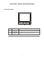
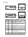
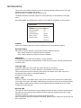
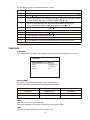
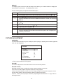
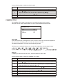
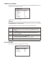
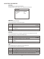
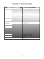
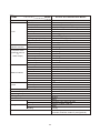
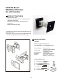
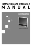
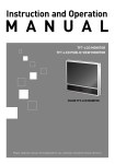
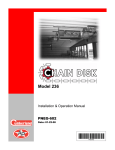
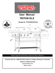
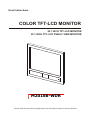
User Instructions
COLOR TFT-LCD MONITOR
20.1 INCH TFT-LCD MONITOR
20.1 INCH TFT-LCD PUBLIC VIEW MONITOR
M201SB-WDR
Please read this manual thoroughly before use and keep it handy for future reference.
LIMITATION OF LIABILITY
THE INFORMATION IN THIS PUBLICATION IS BELIEVED TO BE ACCURATE IN ALL RESPECTS,
HOWEVER, WE CANNOT ASSUME RESPONSIBILITY FOR ANY CONSEQUENCES RESULTING FROM
THE USE THEREOF. THE INFORMATION CONTAINED HEREIN IS SUBJECT TO CHANGE WITHOUT
NOTICE. REVISIONS OR NEW EDITIONS TO THIS PUBLICATION MAY BE ISSUED TO INCORPORATE
SUCH CHANGES.
2
WARNINGS AND CAUTIONS:
TO REDUCE THE RISK OF FIRE OR ELECTRIC SHOCK, DO NOT EXPOSE THIS PRODUCT TO RAIN
OR MOISTURE. DO NOT INSERT ANY METALLIC OBJECTS THROUGH THE VENTILATION GRILLS OR
OTHER OPENINGS ON THE EQUIPMENT.
CAUTION:
CAUTION
RISK OF ELECTRIC SHOCK
DO NOT OPEN
CAUTION: TO REDUCE THE RISK OF ELECTRIC SHOCK,
DO NOT REMOVE COVER(OR BACK).
NO USER-SERVICEABLE PARTS INSIDE.
REFER SERVICING TO QUALIFIED SERVICE PERSONNEL.
EXPLANATION OF GRAPHICAL SYMBOLS
The lightning flash with arrowhead symbol, within an equilateral triangle, is intended to alert
the user to the presence of uninsulated "dangerous voltage" within the product's enclosure
that may be of sufficient magnitude to constitute a risk of electric shock to persons.
The exclamation point within an equilateral triangle is intended to alert the user to the
presence of important operating and maintenance (servicing) instructions in the literature
accompanying the product.
PRECAUTIONS
Safety ----------------------------------------Should any liquid or solid object fall into the
cabinet, unplug the unit and have it checked by the
qualified personnel before operating it any further.
Installation ----------------------------------------Do not install the unit in an extremely hot or humid
place or in a place subject to excessive dust or
mechanical vibration.
Unplug the unit from the wall oulet if it is not going
to be used for several days or more. To disconnect
the cord, pull it out by the plug. Never pull the cord
itself.
Cleaning -----------------------------------------
Allow adequate air circulation to prevent internal
heat build-up. Do not place the unit on surfaces
(rugs, blankets, etc.) or near materials(curtains,
draperies) that may block the ventilation holes.
Clean the unit with a slightly damp soft cloth.
Use a mild household detergent. Never use strong
solvents such as thinner or benzine as they might
damage the finish of the unit.
Height and vertical linearity controls located at the
rear panel are for special adjustments by qualified
personnel only.
Retain the original carton and packing materials for
safe transport of this unit in the future.
The unit is not designed to be waterproof.
Exposure to rain or water may damage the unit.
3
FCC COMPLIANCE STATEMENT
FCC INFORMATION : THIS EQUIPMENT HAS BEEN TESTED AND FOUND TO COMPLY WITH
THE LIMITS FOR A CLASS A DIGITAL DEVICE, PURSUANT TO PART 15 OF THE FCC RULES.
THESE LIMITS ARE DESIGNED TO PROVIDE REASONABLE PROTECTION AGAINST HARMFUL
INTERFERENCE WHEN THE EQUIPMENT IS OPERATED IN A COMMERCIAL ENVIRONMENT.
THIS EQUIPMENT GENERATES, USES, AND CAN RADIATE RADIO FREQUENCY ENERGY AND IF
NOT INSTALLED AND USED IN ACCORDANCE WITH THE INSTRUCTION MANUAL, MAY CAUSE
HARMFUL INTERFERENCE TO RADIO COMMUNICATIONS. OPERATION OF THIS EQUIPMENT
IN A RESIDENTIAL AREA IS LIKELY TO CAUSE HARMFUL INTERFERENCE IN WHICH CASE THE
USER WILL BE REQUIRED TO CORRECT THE INTERFERENCE AT HIS OWN EXPENSE.
CAUTION : CHANGES OR MODIFICATIONS NOT EXPRESSLY APPROVED BY THE PARTY
RESPONSIBLE FOR COMPLIANCE COULD VOID THE USER'S AUTHORITY TO OPERATE THE
EQUIPMENT.
THIS CLASS A DIGITAL APPARATUS COMPLIES WITH CANADIAN ICES-003.
CET APPAREIL NUMERIQUE DE LA CLASSE A EST CONFORME A LA NORME NMB-003 DU
CANADA.
CE COMPLIANCE STATEMENT
WARNING
This is a Class A product. In a domestic environment this product may cause radio interference in
which case the user may be required to take adequate measures.
4
IMPORTANT SAFEGUARDS
1. READ INSTRUCTIONS -- All the safety and operating
instructions should be read before the appliance is
operated.
10. POWER CORDS -- Protect the power cord from being
walked on or pinched particularly at plugs, convenience
receptacles, and the point where they exit from the
apparatus.
2. RETAIN INSTRUCTIONS -- The safety and operating
instructions should be retained for future reference.
11. HEED WARNINGS -- Follow all instructions marked on the
video monitor or equipment.
3. CLEANING -- Unplug video monitor or equipment from the
wall outlet before cleaning. Do not use liquid cleaners or
aerosol cleaners. Use a damp cloth for cleaning.
12. LIGHTNING -- For added protection for video monitor or
equipment during a lightning storm, or when it is left
unattended and unused for long periods of time, unplug it
from the wall outlet and disconnect the antenna or cable
system. This will prevent damage to the video product due
to lightning and power-line surges.
4. ATTACHMENTS -- Do not use attachments not
recommended by the video monitor or equipment
manufacturer as they may result in the risk of fire, electric
shock or injury to persons.
13. OVERLOADING --Do not overload wall outlets and
extension cords as this can result in a risk of fire or electric
shock.
5. WATER AND MOISTURE -- Do not use video monitor or
equipment near water -- for example, near a bathtub,
washbowl, kitchen sink, laundry tub, in a wet basement, or
near a swimming pool, or the like.
14. OBJECT AND LIQUID ENTRY -- Never push objects of
any kind into video monitor or equipment through openings
as they may touch dangerous voltage points or short-out
parts that could result in a fire or electric shock. Never spill
liquid of any kind on the product.
6. ACCESSORIES -- Do not place video monitor or
equipment on an unstable cart, stand or table. The video
monitor or equipment may fall, causing serious injury to a
child or adult, and serious damage to the equipment. Wall
or shelf mounting should follow the manufacturer's
instructions, and should use a mounting kit approved by the
manufacturer.
15. SERVICING -- Do not attempt to service video monitor or
equipment yourself as opening or removing covers may
expose you to dangerous voltage or other hazards. Refer
all servicing to qualified service personnel.
6A. Video monitor or equipment and cart
combinations should be moved with
care. Quick stops, excessive force,
and uneven surfaces may cause the
equipment and cart combination to overturn.
16. DAMAGE REQUIRING SERVICE -- Unplug video monitor
or equipment from the wall outlet and refer servicing to
qualified service personnel under the following conditions:
A. When the power-supply cord or the plug has been
damaged.
B. If liquid has spilled, or objects have fallen into the video
product.
C. If the video product has been exposed to rain or water.
D. If the video product does not operate normally by
following the operating instructions, adjust only those
controls that are covered by the operating instructions as
an improper adjustment of other controls may result in
damage and will often require extensive work by a qualified
technician to restore the video product to its normal
operation.
E. If the video product has been dropped, or the cabinet
damaged.
F. When the video product exhibits a distinct change in
performance -- this indicates a need for service.
7. VENTILATION -- Slots and openings in the cabinet and the
back or bottom are provided for ventilation, and to ensure
reliable operation of the video monitor or equipment and to
protect it from overheating. These openings must not be
blocked or covered. The openings should never be blocked
by placing the video monitor or equipment on a bed, sofa,
rug, or other similar surface. Video monitor or equipment
should never be placed near or over a radiator or heat
register. Video monitor or equipment receiver should not be
placed in a built-in installation such as a bookcase unless
proper ventilation is provided.
8. POWER SOURCES -- Video monitor or equipment should
be operated only from the type of power source indicated
on the marking label. If you are not sure of the type of power
supplied to your home, consult your video monitor or
equipment dealer or local power company. For video
monitor or equipment designed to operate from battery
power refer to the operating instructions.
17. REPLACEMENT PARTS -- When replacement parts are
required, be sure the service technician has used
replacement parts specified by the manufacturer or that
have the same characteristics as the original part.
Unauthorized substitutions may result in fire, electric shock
or other hazards.
9. GROUNDING OR POLARIZATION -- This video monitor
may be equipped with a polarized alternating - current line
plug (a plug having one blade wider than the other). This
plug will fit into the power outlet only one way. This is a
safety feature. If you are unable to insert the plug fully into
the outlet, try reversing the plug. If the plug should still fail to
fit, contact your electrician to replace your obsolete outlet.
Do not defeat the safety purpose of the polarized plug.
18. SAFETY CHECK -- Upon completion of any service or
repairs to this video product, ask the service technician to
perform safety checks to determine that the video product
is in proper operating condition.
19. FIELD INSTALLATION -- This installation should be made
by a qualified service person and should conform to all
local codes.
Alternate Warnings - This video monitor is equipped with a
three-wire grounding-type plug, a plug having a third
(grounding) pin. This plug will only fit into a grounding-type
power outlet. This is a safety feature. If you are unable to
insert the plug into the outlet, contact your electrician to
replace your obsolete outlet. Do not defeat the safety
purpose of the grounding-type plug.
20. Do not install near any heat sources such as radiators, heat
registers, stoves, or other apparatus (including amplifiers)
that product heat.
5
TABLE OF CONTENTS
CHAPTER 1.
FEATURES
7
DESCRIPTION
7
FEATURES
7
ACCESSORIES
7
CHAPTER 2.
FRONT AND REAR PANEL
8
THE FRONT PANEL
8
THE REAR PANEL
9
CHAPTER 3.
REMOTE CONTROL
10
CHAPTER 4.
SETUP MODE
11
OVERVIEW
11
OSD WINDOW OF MAIN MENU
11
SELECTING SCREEN MODE
12
MOTION SETUP
13
TIME/DATE
14
PICTURE ADJUSTMENT
15
CAMERA TITLE
16
CAMERA ADJUSTMENT
17
PIP ADJUSTMENT
18
CONFIGURATION
18
ADJUSTING OSD WINDOW
20
CHAPTER 5.
TROUBLESHOOTING
21
CHAPTER 6.
SPECIFICATIONS
22
6
CHAPTER 1. FEATURES
DESCRIPTION
The 20.1" Color TFT-LCD Monitor can display up to two video sources.
The monitor features built-in video motion detection (VMD) allowing the monitor image to switch
to one or both of the camera images which contains motion.
The monitor provides five display modes including full-screen (CAM1 or CAM2), picture-inpicture (PIP) mode and picture-by-picture (PBP) mode.
All monitor programming is accomplished via an IR remote control.
FEATURES
·
·
·
·
·
·
·
·
·
High Brightness and Contrast Color TFT-LCD Monitor
High Resolution Display
Motion Detection Capability
PIP & PBP Display
Fully Programmable via remote control
Built-in Light Sensor
Three Video Output Connectors
Flip Cover On The Rear Panel
DC 12 Volts Output
ACCESSORIES
Please make sure the following items are included with your LCD Monitor.
If any items are missing, contact your dealer.
Power Cord
DC Adapter
Remote Control
7
User Manual
CHAPTER 2. FRONT AND REAR PANEL
THE FRONT PANEL
B
Part
Function
A
IR /
LIGHT SENSOR
B
INTEGRATED
CAMERA
A
Description
Remote control sensor / Light sensor for detecting ambient light.
Integrated camera window.(Public View Monitor)
8
THE REAR PANEL
A
B
C
D
E
F
L
CA1 IN
CA2 IN
CA1 OUT
CA2 OUT
R
AUDIO
MAIN
DC 12V IN DC 12V OUT
< 20.1 Inch TFT-LCD Monitor >
A
B
G
H
E
CA2
IN/OUT
CA1 OUT
MAIN
F
L
DC 12V IN DC 12V OUT
R
AUDIO
< 20.1 Inch TFT-LCD Public View Monitor >
FUNCTION
PART
LABEL
A
DC 12V IN
Connect the adapter jack to the DC power connector on the
back of the monitor
B
DC 12V OUT
DC output connector for an external camera.
(DC 12V / 500mA)
C
CA1/CA2 IN
Video input connectors of the CA1 (Camera 1) and the
CA2 (Camera 2) video sources.
Use the BNC connections.
D
CA1/CA2 OUT
Video output connectors of the CA1 (Camera 1) and the
CA2 (Camera 2)
E
MAIN
The video output connector -The same video as the picture
displayed.
F
AUDIO
Audio Input connector
G
CA2 IN/OUT
Video input connectors of the CA2 (Camera 2) video sources.
Use the BNC connections.
Either left or right BNC can be input or output
The connectors have auto-termination internal switches.
H
CA1 OUT
The video output connector of the integrated camera
9
CHAPTER 3. REMOTE CONTROL
1.
Mute
Cuts off the sound.
2.
Zoom
Not available.
3.
4.
5.
10
VCR
Not available.
11
Up/Down Keys
Moves up/down in the OSD menu.
Increases/decreases audio volume.
1
CA1
CA2
CA3
1
2
3
4
5
6
7
8
CA4
FREEZE
CAPTURE
13
VCR
VOLUME
3
4
MENU
5
14
SEQUENCE
6.
7.
QUAD
Changes the picture display mode on the screen.
POP
Not available.
9.
S-Video
Not available.
15
16
QUAD
6
VOLUME
REPLAY HISTORY DISPLAY
17
Display
Displays setup information.
8.
2
0
12
Left/Right Keys
Displays sub-menu of selected item in the OSD.
Decreases/increases the chosen item.
9
ZOOM
7
PB
S-VIDEO
POP
PC
COMPONENT
ID
18
19
20
10. Power
Turns the monitor on or off.
11. Numbers (0~9)
1~2(CA1~2) : Displays the selected camera in full
On the screen.
3~9, 0 : Not available.
12. Freeze
Not available.
17. Replay
Not available.
13. Capture
Not available.
18. PB
Not available.
14. Menu
Turns the OSD menu on/off.
19. PC
Not available.
15. Sequence
Sequences the picture from CA1 to CA2.
20. Component
Not available.
16. History
Not available.
21. ID
Not available.
10
8
9
21
CHAPTER 4. SETUP MODE
OVERVIEW
All functions are controlled via the supplied remote control.
Pressing the MENU button places the unit into the programming mode.
In the programming mode, the arrow buttons are used to move the cursor DOWN, UP, LEFT and
RIGHT in the OSD Setup menu.
The selected values are saved when exiting the OSD menu.
OSD WINDOW OF MAIN MENU
MAIN MENU
SCREEN MODE
MOTION SET
TIME/DATE
PICTURE
CAMERA TITLE
CAMERA ADJUST
PIP
CONFIGURATION
OSD MENU
MODE1
This monitor has 9 main OSD items.
Press the MENU button to turn the main OSD Menu on or off.
The MENU button is also used to go to the previous OSD menu.
Use UP(DOWN) button to move up(down) in the OSD menu.
Use LEFT or RIGHT button to display the sub-menu of the item where the horizontal indication
bar is located or decrease or increase the amount of the selected item.
11
SELECTING SCREEN MODE
SCREEN MODE is used to select how the camera image is displayed on the screen.
There are 5 options available.
Use the QUAD button on the remote control to change the SCREEN MODE.
ITEMS
DESCRIPTIONS
MODE 1
Full display of the camera chosen to display on the screen.
CA1
The screen is switched to the camera which contains motion when
the camera MOTION is enabled.
The screen will be PBP (cameras are displayed side by side) if motion
occurs within the field of both cameras.
MODE 2
Main + PIP
The main window and the PIP window are exchanged when motion
occurs on PIP windows.
CA1
User can select CA1 or CA2 as the PIP window video source.
If CA2 is selected as the PIP window, CA1 will be the main window.
MODE 3
Main + PIP
The PIP window appears if motion occurs on the PIP camera and then
disappears after DWELL TIME expires.
The DWELL TIME is set the MOTION SET menu.
CA1
MODE 4
CA1
PBP display
Half of the horizontal area is cropped on each camera.
The screen switches to full display when motion occurs within the filed
view of one of the cameras.
Each camera's horizontal display position can be adjusted.
CA2
MODE 5
CA1
PBP display
Full area of each camera is displayed on the screen side by side, but
the areas cannot be manipulated horizontally.
CA2
Use the following steps to set the SCREEN MODE option.
ACTION
STEP
1
Press MENU button and then select DISPLAY MODE using
2
Press
3
Press MENU button to exit from main OSD window.
or
button to change the display mode.
12
or
.
MOTION SETUP
This monitor has a motion detection function to support automatic switching from one of the
cameras to the other camera with motion.
Motion detection is available on both camera inputs.
The Motion Sensitivity and other options for motion detection can be adjusted in this setup
menu.
MOTION ENABLE and SENSITIVITY options can be adjusted individually on each camera.
MOTION SET
CAMERA
CA1
MOTION ENABLE
ON
SENSITIVITY
10
CAPTURE TIME
05 SEC
DWELL TIME
05 SEC
MOTION TIME
18:00:0006:00:00
CAMERA
This menu is used to select the camera for adjustment of motion detection options.
MOTION ENABLE
This option is used to activate or deactivate the motion detection function.
· "ON" : Motion detection of selected camera is enabled.
· "OFF" : Motion detection of selected camera is disabled.
SENSITIVITY
Use SENSITIVITY to adjust the sensitivity of motion detection.
To increase (decrease) the motion detection sensitivity of the camera, increase (decrease) the
sensitivity value.
CAPTURE TIME
CAPTURE TIME is the interval that the motion detection is processed.
When it is set to 5 SEC, the motion detection is processed at every five seconds.
This means that the minimum switching interval from the camera to the other camera is 5
seconds when this monitor is operated in MODE 1.
It supports up to 99 seconds.
DWELL TIME
If there is a motion in the field of view of the CA2, the main screen switches to the CA2 image
for a length of time set in the DWELL TIME setup menu and then returns to the previous screen
mode. DWELL TIME is the time that the motion detected camera is displayed on the screen.
It supports up to 99 seconds.
MOTION TIME
This option is used to set when the motion detection function is active. The time represented by
the upper line is the start of motion detection and the lower line represents the end of motion
detection time period.
The motion detection function only works during MOTION TIME.
If the user want to use motion detection all the time, adjust the time of lower line sooner than the
time of upper line.
13
Use the following steps to adjust MOTION SET options.
ACTION
STEP
1
Press MENU and then move the indication bar to MOTION SET using
2
Press
3
Move the indication bar to CAMERA using or and then select the camera
(CA1 or CA2) for adjustment of MOTION SET using
or .
4
Move the indication bar to the item (MOTION ENABLE, SENSITIVITY,
CAPTURE TIME or DWELL TIME) to be adjusted using or .
5
Adjust the option selected using
6
Move the indication bar to MOTION TIME using
7
Select one of the options using
8
Adjust the option selected using
9
Press MENU to display the previous OSD window.
10
Press MENU to go to the previous OSD window or exit from the OSD.
or
or
.
to display sub-menu of MOTION SET.
or
or
.
or
.
.
or
.
TIME/DATE
OVERVIEW
The TIME/DATE menu allows you to adjust current time and date for display on the screen.
TIME/DATE
DATE FORMAT
US
DATE
MM/DD/YYYY
TIME
HH/MM/SS
DISPLAY
ON
DATE FORMAT
The option on the time and date setup screen is date format.
This is used to select between the following three date formats:
FORMAT
DISPLAY
EXAMPLE
US (default)
MM/DD/YYYY
01/01/2004
EURO
DD/MM/YYY
01/01/2004
ASIA
YYYY/MM/DD
2004/01/01
DATE
This field is used to set the current date.
The format displayed on the screen is dependent on the format option.
TIME
This field is used to set the time in the 24-hour format.
14
DISPLAY
The display option on the time and date setup screen allows you to select whether to display the
time and date on the screen. The default option is ON.
Use the following steps to adjust the DATE/TIME option.
ACTION
STEP
1
Press MENU and then move the indication bar to DATE/TIME using
2
Press
3
Move the indication bar to DATE FORMAT and select the format you want using
or .
4
Move the indication bar to the item (DATE or TIME) to be adjusted using
or .
5
Select one of the option using
6
Adjust the option using
7
Press MENU to display the previous OSD window.
8
Move the indication bar to DISPLAY and select the option "ON" to display time
and date on the screen.
9
Press MENU to go to the previous OSD window or exit from the OSD.
or
or
.
to display sub-menu of DATE/TIME.
or
or
.
.
PICTURE ADJUSTMENT
OVERVIEW
The PICTURE menu allows you to modify the picture quality by adjusting the contrast, brightness,
color, tint and sharpness.
PICTURE
VOLUME
00
CONTRAST
19
BRIGHTNESS
19
COLOR
50
TINT
501)
SHARPNESS
06
MOTION ADJUST
2
1) Tint is only activated in NTSC system.
VOLUME
The volume adjustment controls the audio level to the internal speakers.
MOTION ADJUST
MOTION ADJUST does not affect the motion detection settings of cameras.
This control is used to adjust the picture quality of moving images.
At times unwanted artifacts can be seen on the edge of objects moving fast through the scene.
A lower value results in improved picture quality for images moving fast.
However, a better picture quality is obtained by adjusting MOTION ADJUST to a larger value in
still image scenes.
15
Use the following steps to adjust the picture quality.
ACTION
STEP
1
Press MENU and then move the indication bar to PICTURE using
2
Press
3
Move the indication bar to the item to be adjusted using
4
Adjust the option selected using
5
Press MENU to go to the previous OSD window or exit from the OSD.
or
or
.
to display sub-menu of PICTURE.
or
or
.
.
CAMERA TITLE
The CAMERA TITLE setup screen allows you to modify the name of each camera.
This option is also used to select whether or not the screen displays the camera title.
CAMERA TITLE
CA1
CA1
CA2
CA2
DISPLAY
ON
CA1 & CA2
An 8-character title can be designated for each camera or video input, and this title appears on
the screen when the display option is ON and the camera is selected.
The default camera title is "CA" with the corresponding number.
Following are the available characters for camera titles regardless of the language setting :
DISPLAY
To display the camera title on the screen, select the DISPLAY option "ON".
Use the following steps to adjust the CAMERA TITLE option.
ACTION
STEP
1
Press MENU and then move the indication bar to CAMERA TITLE using
2
Press
3
Move the indication bar to the item to be adjusted (CA1 or CA2) and select the
character position of the title using
or .
4
Change the character of the title selected using
5
Press MENU to display the previous OSD window.
6
Move the indication bar to DISPLAY using
7
Select the DISPLAY option "ON" or "OFF".
8
Press MENU to go to the previous OSD window or exit from the OSD.
or
or
to display the sub-menu of CAMERA TITLE.
16
or
or
.
.
.
CAMERA ADJUSTMENT
The picture quality of each camera can be adjusted by using the CAMERA ADJUST setup menu.
This setup menu is composed of 7 options.
CAMERA ADJUST
CAMERA
CA1
CONTRAST
25
BRIGHTNESS
25
COLOR
25
TINT *
25
SHARPNESS
01
SEQUENCE
03 SEC
*) Tint is only activated in NTSC system.
SEQUENCE
This option is used to set the dwell time of the selected camera when the monitor is operated in
the SEQUENCE mode. The picture sequences in the order of CA1, CA2, CA1, CA2.. by pressing
the SEQUENCE button on the remote control.
Use the following steps to set the picture quality of each camera and other options.
ACTION
STEP
1
Press MENU and then move the horizontal bar to CAMERA ADJUST using
or .
2
Press
3
Locate the horizontal bar at CAMERA and then select the camera to be
adjusted using
or .
4
Select the option to be adjusted using
5
Adjust the option selected using
or .
- Only the picture quality of the selected camera is adjusted.
6
Press MENU to go to the previous menu or exit from the OSD menu.
or
to display sub-menu of CAMERA ADJUST.
or
PIP ADJUSTMENT
This setup menu is used to adjust the PIP position and size.
PIP
PIP SIZE
00
PIP H POS
008
PIP V POS
005
PIP CAMERA
CA2
17
.
PIP SIZE
The PIP window size can be adjusted by using the PIP SIZE menu option.
Larger PIP window sizes can be obtained by increasing the PIP SIZE value.
PIP H&V POS
The PIP window can be displayed in any position on the screen by adjusting these options.
The PIP position is dependent on the PIP size, so care must be exercised not to display PIP
window beyond the border of the screen.
PIP CAMERA
This option is used to select which camera is designated as the PIP window.
If CA1 is designated as the PIP window, CA2 will be the Main window.
This option is only applied on SCREEN MODE 2 & 3.
Use the following steps to set PIP options.
ACTION
STEP
1
Press MENU and then move the horizontal bar to PIP option using
2
Press
3
Select the option to be adjusted using
4
Adjust the option selected using
5
Press MENU to go to the previous menu or exit from the OSD menu.
or
or
.
to display sub-menu of PIP.
or
or
.
.
CONFIGURATION
CONFIGURATION
VIDEO SYSTEM
NTSC
PHOTO INPUT
OFF
RECALL
OFF
AUTO POWER
OFF
ON TIME
09:00:00
OFF TIME
18:00:00
VIDEO SYSTEM
Select the video system that is used in your region.
Use the following steps to set the video system.
ACTION
STEP
1
Press MENU and then move the horizontal bar to CONFIGURATION using
or .
2
Press
3
Locate horizontal bar at VIDEO SYSTEM and then select NTSC or PAL
using
or .
4
Press MENU to go to the previous menu or exit from the OSD menu.
or
to display sub-menu of CONFIGURATION.
18
PHOTO INPUT
This monitor can be turned off and goes to power saving mode if there is low ambient light by
setting PHOTO INPUT to "ON".
Use the following steps to set the PHOTO INPUT option.
ACTION
STEP
1
Press MENU and then move the horizontal bar to CONFIGURATION using
or .
2
Press
3
Locate horizontal bar at PHOTO INPUT and then select ON of OFF using
or .
- ON : The monitor turns off when ambient light is low.
- OFF : The monitor doesn't go to low power mode.
4
Press MENU to go to the previous menu or exit from the OSD menu.
or
to display sub-menu of CONFIGURATION.
RECALL
This option allows you to return the unit to factory-defined defaults.
Some items do not go to factory default values.
ACTION
STEP
1
Press MENU and then move the horizontal bar to CONFIGURATION using
or .
2
Press
3
Locate horizontal bar at RECALL and then select ON using
4
Press MENU to make the monitor factory default state.
or
to display sub-menu of CONFIGURATION.
or
.
AUTO POWER
This option is used to turn the monitor on and off automatically at ON TIME and OFF TIME.
Use the following steps to adjust the ON and OFF TIME.
ACTION
STEP
1
Press MENU and then move the indication bar to CONFIGURATION
using or .
2
Press
3
Move the indication bar to AUTO POWER and select ON or OFF using
4
Move the indication bar to ON TIME or OFF TIME using
5
Select one of the option using
6
Adjust the selected option using
7
Press MENU to display the previous OSD window or exit from the OSD.
or
to display sub-menu of CONFIGURATION.
19
or
or
or
.
.
.
or
.
ADJUSTING OSD WINDOW
OVERVIEW
Use the OSD Menu to adjust the OSD window.
The OSD Position and other options can be adjusted in this setup menu.
OSD MENU
LANGUAGE
ENGLISH
BLENDING
ON
TIME
40 SEC
LANGUAGE
Selects OSD language displayed.
Use the following steps to change OSD language.
ACTION
STEP
1
Press MENU and then move the horizontal bar to OSD MENU using
2
Press
3
Locate the horizontal bar at LANGUAGE and then choose the desired language
using
or .
4
Press MENU to go to the previous menu or exit from the OSD menu.
or
or
.
to display sub-menu of OSD MENU.
BLENDING
Use the Blending setup menu to change the opaqueness of the background of the OSD.
Use the following steps to change the BLENDING option.
ACTION
STEP
1
Press MENU and then move the horizontal bar to OSD MENU using
2
Press
3
Locate the horizontal bar at BLENDING and then choose "ON" or "OFF" using
or .
4
Press MENU to go to the previous menu or exit from the OSD menu.
or
or
.
to display sub-menu of OSD MENU.
TIME
Use the TIME setup menu to adjust the on-screen display time.
Use the following steps to change the OSD time.
ACTION
STEP
1
Press MENU and then move the horizontal bar to OSD MENU using
2
Press
3
Locate the horizontal bar at TIME and then select preferred time using
4
Press MENU to go to the previous menu or exit from the OSD menu.
or
or
.
to display sub-menu of OSD MENU.
20
or
.
CHAPTER 5. TROUBLESHOOTING
1.
Screen is black and power indicator is off.
·
Ensure that the power cord is firmly connected and the LCD monitor is on.
·
Check PHOTO INPUT adjustment.
2.
No Picture.
·
Check the signal connections.
3.
The image is too light or too dark.
·
Adjust the Brightness and Contrast.
4.
Picture is impropely tinted.
·
Check color adjustment.
5.
Motion not detected or detected too often.
·
Adjust sensitivity of motion detection.
6.
Remote control malfunctions.
·
Check the battery terminals.
·
Replace the remote control batteries.
7.
No sound.
·
Ensure that the audio cables are firmly connected to both the audio-in ports on your monitor.
·
Check the volume level.
21
CHAPTER 6. SPECIFICATIONS
MODEL
ITEMS
LCD
Video Input
LCD Panel
Active Display Area
Pixel Format
Pixel Pitch
Color Depths
Contrast Ratio
Brightness
Viewing Angles (L/R/U/D)
Light Source / Lifetime
Response Time
Camera Video Input Connector
Video Mode
Video Input Level
Video Output Connector
Video Output
Audio
Video Output Level
Audio Input level
Audio Input Connector
Audio Amplifier
Power Requirement
Power Consumption
Operating Temperature
Storage Temperature
Case Material
Dimensions
Net
Packing
Weight
Net
Packing
Accessories
22
20.1 Inch TFT-LCD Color Monitor
20.1 inches (510.54 mm) TFT LCD Panel
408.0 mm(H) x 306.0 mm(V)
640(H) x 480(V), RGB vertical stripe
0.6375 mm x 0.6375 mm
8 Bit / 16.7M Colors
800 : 1 (Typical)
450 cd/m2 (Typical)
89 / 89 / 89 / 89 (Typical)
6CCFL / 50,000Hrs (Minimum)
25 ms (Typical)
BNC x 2
NTSC/ PAL
1.0Vp-p @ 75 ohm
BNC x 3
- Video Output x 2
- Main Output x 1
1.0Vp-p @ 75 ohm
Line level
RCA x 2
2.5 W x 2
DC12V / 4.9A, DC Output Jack 12V 0.5A(Max)
60 Watts
0~40oC
0~50oC
Metal
472.4mm x 451.4mm x 62mm
640mm x 540mm x190 mm
8.6kg
12.4kg
AC-DC Adapter, Power Cord, Manual,
Remote Controller
MODEL
ITEMS
Input
LCD
Composite Video
(Built-In Camera)
Composite Video
(External Camera
&
Video Output)
Built-In Camera
Audio
Display Source
LCD Panel
Active Display Area
Pixel Format
Pixel Pitch
Color Depths
Contrast Ratio
Brightness
Viewing Angles (L/R/U/D)
Light Source / Lifetime
Response Time
Video Mode
Camera Video Input Level
Video Mode
Camera Video Input Level
Camera Video Input Connector
Video Output Level
Video Output Connector
Monitor Output Level
Monitor Output Connector
CCD Image Sensor
Resolution
Sensitivity
S/N Ratio
Auto Iris
Auto White Balance
Electronic Shutter
VF Lens
Audio Input level
Audio Input Connector
Audio Amplifier
Power Requirement
Power Consumption
Operating Temperature
Storage Temperature
Case Material
Dimensions
Net
Packing
Weight
Net
Packing
Accessories
23
20.1 Inch TFT-LCD Public View Monitor
Built-in Camera Video + External Camera Video
20.1 inches (510.54 mm) TFT LCD Panel
408.0 mm(H) x 306.0 mm(V)
640(H) x 480(V), RGB vertical stripe
0.6375 mm x 0.6375 mm
8 Bit / 16.7M Colors
800 : 1 (Typical)
450 cd/m2 (Typical)
89 / 89 / 89 / 89 (Typical)
6CCFL / 50,000Hrs (Minimum)
25ms (Typical)
NTSC/ PAL
1.0Vp-p @ 75 ohm
NTSC/ PAL
1.0Vp-p @ 75 ohm
BNC x 1
1.0Vp-p @ 75 ohm
BNC x 3
1.0Vp-p @ 75 ohm
BNC x 1
1/3''
470 TVL
1 Lux ( F2.0 , 50 IRE )
50dB
Yes
Yes
1/60 ~ 1/100,000, 1/50 ~ 1/100,000 Sec
4 9mm ( F 2.0 ~ 2.8 )
Line level
RCA x 2
2.5 W x 2
DC 12V (Adaptor), DC Output Jack 12V 500mA
60 Watts
0~40oC
0~50oC
Metal
472.4mm x 451.4mm x 89.4mm
640mm x 540mm x190 mm
8.9kg
12.7kg
AC-DC Adapter, Power Cord, Manual, Remote
Controller, Extension Cable for power(optional)
HCS775 Mount
Light Duty Ceiling LCD Mount Bracket
15", 17", 19", 20.1" LCD Monitors
FEATURES
-
Adjustable swivel head (Pan 180o, Tilt +/-15")
75mm or 100mm VESA compatible
Die cast and aluminum construction
Cable feed-through to conceal wiring
1,1/4" NPT standard pipe
Maximum load 20 lbs (9.0kg)
USE
The bracket is designed for industry standard LCD monitors.
The mount is intended for use in ceiling mount applications.
ASSEMBLY
The ceiling mounting plate (1) must be attached to a structural object such as hard wood, ceiling rafter or
concrete that will support the weight of the mount and monitor. The mounting plate may be attached using
the M6 x 35 (3X) or substitute hardware as required providing a secure attachment.
The VESA plate must be attached to the ball socket stem using the two M5 x 16L machine screws and tooth
washers.
NOTE: PROPER ORIENTATION OF THE BALL-SOCKET ASSEMBLY IS REQUIRED FOR CEILING
INSTALLATION.
IMPROPER INSTALLATION WILL BREAK THE SOCKET AND MAY CAUSE THE MONITOR TO FALL.
Check if the installation requires ceiling mounting of the LCD. The orientation of the ball socket to ball
socket adapter may be changed by unscrewing the Allen screw inside the adapter, repositioning the adapter
to the top or side position on the socket and reattaching the adapter to the socket.
Tighten the inside Allen screw firmly.
If ceiling mount is required, ensure the ball socket is orientated in a "C" shape with the ball socket adapter
located at the 12:00 o'clock position(Vertical direction) in relationship to the ball socket.
(See ceiling mount configuration)
Attach the extended length of pipe to the 1,1/2" ceiling mount (1). Attach the VESA plate (2) to the back of
the LCD monitor using the four M4 x 8L machine screws. Both 75mm and 100mm VESA mounts are
accommodated.
24
Rotate monitor and mount assembly to the desired location and tighten the two remaining ball socket
screws firmly.
Tighten the pole set screws ( ) with the supplied wrench.
o
0
12
6.5
112
(1)
Key Hole
Lock Screw
Pivot
Screw
(Ceiling mount configuration)
(2)
Unit: mm
3.94(100)
2.95(75)
4.72(120)
19.49(495)
18.50(470)
11.81(300)
1.97
(50)
129
o
15
2.95(75)
3.94(100)
5.20(132)
-15 o
Unit: Inch(mm)
SPECIFICATION
Pan adjustment
Tilt adjustment
LCD mounting hardware
180O
-15O ~ +15O
Qty 4 M4 x 8L (VESA plate)
Qty 2 M5 x 16L (Ball socket)
Qty 2 Star washers (Ball socket)
Qty 3 M6 x 35 (Lag Screws)
Qty 3 Ceiling anchors
Qty 2 M4 x 4L (Set screws)
Construction
Finish
Die Cast and aluminum
Light-gray or black polyester powder-cost
Maximum load
20 lbs (9.0 kg)
Dimensions
Weight
See dimensional outline
Unit 4.4 lbs (2.0kg)
Shipping 5.5 lbs (2.5kg)
25
HCS775-E Mount
Light Duty Ceiling LCD Mount Bracket
15", 17", 19", 20.1" LCD Monitors
FEATURES
-
-
Adjustable extension length (26.4" to 36.6")
(670mm to 930mm)
Three fixed extension lengths 26.4" (670mm),
31.5" (800mm) or 36.6" (930mm)
Interior pole may be used as a 19.7" (500mm)
extension with use of purchased 1,1/2" to
1,1/4" NPT reducer
Adjustable swivel head (Pan 180o, Tilt +/-15")
75mm or 100mm VESA compatible
Die cast and aluminum construction
Cable feed-through to conceal wiring
1, 1/2" NPT / 1,1/4" NPT standard pipe
Maximum load 20 lbs (9.0kg)
Extension Type
USE
The bracket is designed for industry standard LCD monitors. The mount is intended for use in ceiling mount
applications when adjustment of the pipe length may be required.
ASSEMBLY
The 1,1/2" ceiling mounting plate (1) must be attached to a structural object such as hard wood, ceiling rafter
or concrete that will support the weight of the mount and monitor. The mounting plate may be attached using
the M6 x 35 (3X) or substitute hardware as required providing a secure attachment.
The VESA plate must be attached to the ball socket stem using the two M5 x 16L machine screws and tooth
washers.
Insert the threaded 1,1/4" NPT pipe into the 1,1/2" NPT pipe at the required length and fasten the
poles together using the four M6 x 12L Allen-head machine screws and split washers.
NOTE: PROPER ORIENTATION OF THE BALL-SOCKET ASSEMBLY IS REQUIRED FOR CEILING
INSTALLATION.
IMPROPER INSTALLATION WILL BREAK THE SOCKET AND MAY CAUSE THE MONITOR TO FALL.
Check if the installation requires ceiling mounting of the LCD. The orientation of the ball socket to ball
socket adapter may be changed by unscrewing the Allen screw inside the adapter, repositioning the adapter
to the top or side position on the socket and reattaching the adapter to the socket.
Tighten the inside Allen screw firmly.
If ceiling mount is required, ensure the ball socket is orientated in a "C" shape with the ball socket adapter
located at the 12:00 o'clock position(Vertical direction) in relationship to the ball socket.
(See ceiling mount configuration)
Attach the extended length of pipe to the 1,1/2" ceiling mount (1). Attach the VESA plate (2) to the back of
the LCD monitor using the four M4 x 8L machine screws. Both 75mm and 100mm VESA mounts are
accommodated.
26
Rotate monitor and mount assembly to the desired location and tighten the two remaining ball socket screws
firmly.
Tighten the pole set screws ( ) with the supplied wrench.
o
0
12
6.5
112
(1)
Key Hole
Pivot
Screw
Lock Screw
(Ceiling mount configuration)
(2)
26.4 (670)
3.94(100)
2.95(75)
4.72(120)
2.95(75)
3.94(100)
5.20(132)
-1
5
36.6(930)
o
15
o
Unit: Inch(mm)
SPECIFICATION
Pan adjustment
Tilt adjustment
LCD mounting hardware
Construction
Finish
Dimensions
Weight
180O
-15O ~ +15O
Qty 4 M4 x 8L (VESA plate)
Qty 2 M5 x 16L (Ball socket)
Qty 2 Star washers (Ball socket)
Qty 4 M6 x 12L (Pipe extensions)
Qty 4 split washer (Pipe extensions)
Qty 3 M6 x 35 (Lag Screws)
Qty 3 Ceiling anchors
Qty 2 M4 X 4L (Set screws)
Die Cast and aluminum
Light-gray or black polyester powder-cost
See dimensional outline
Unit 6.6 lbs (3.0kg)
Shipping 7.7 lbs (3.5kg)
27
HCS37G Mount
Wall Mount Bracket
for LCD monitor
PRODUCT FEATURES
-
Light duty wall mount
Conform to the VESA 75mm or 100mm standard
Adjustable swivel head
Durable steel construction and hardened zinc
metal frame
Maximum load 29 lb (13kg)
The HMS37G is light duty wall mount designed for use
With LCD monitor.
This mount is for use in wall mounting applications and
is capable of supporting loads up to 29 lb (13 kg).
SPECIFICATION
GENERAL
Swivels to right and left up to 180o
Pivots upwards to 10o and downwards to 25o
LCD mounting
Construction
Maximum load
Dimension
Weight
four(4) M4 x 8L
machine screw (supplied)
Durable steel &
hardened zinc metal
29 lb (13 kg)
See dimensional outline
Unit : 2.2 lb (1.0 kg)
Shipping : 3.3 lb (1.5 kg)
FITTING CHECK-LIST
Unit: mm
28
01
Small Screw
9pcs
02
Nut
1pcs
03
Cable Holder
1pcs
04
Cable Tie
3pcs
05
Wrench
1pcs
06
Connector Plate
1pcs
MEMO
29
MEMO
30
20.1 INCH TFT-LCD MONITOR
20.1 INCH TFT-LCD PUBLIC VIEW MONITOR
50301791B