1
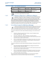
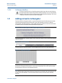
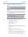
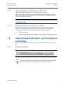
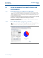
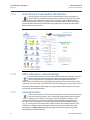
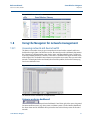
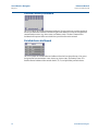
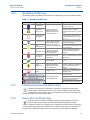
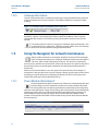
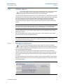
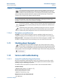
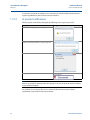
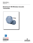
Reference Manual 00809-0100-4423, Rev AB May 2014 Emerson® Smart Wireless Navigator Smart Wireless Navigator May 2014 Reference Manual 00809-0100-4423, Rev AB Contents Theory of operation . . . . . . . . . . . . . . . . . . . . . . . . . . . . . . . . . . . . . . . . . . . . . . . . . . . . . . . . . page 3 Installing the Navigator machine . . . . . . . . . . . . . . . . . . . . . . . . . . . . . . . . . . . . . . . . . . . . . . page 3 Launching Navigator . . . . . . . . . . . . . . . . . . . . . . . . . . . . . . . . . . . . . . . . . . . . . . . . . . . . . . . . page 5 Navigator security . . . . . . . . . . . . . . . . . . . . . . . . . . . . . . . . . . . . . . . . . . . . . . . . . . . . . . . . . . . page 5 Adding networks to Navigator . . . . . . . . . . . . . . . . . . . . . . . . . . . . . . . . . . . . . . . . . . . . . . . . page 7 Understanding the Navigator - general layout and terminology . . . . . . . . . . . . . . . . . . . page 9 Using the Navigator for network planning and commissioning . . . . . . . . . . . . . . . . . . . . page 11 Using the Navigator for network management . . . . . . . . . . . . . . . . . . . . . . . . . . . . . . . . . . page 13 Using the Navigator for network maintenance . . . . . . . . . . . . . . . . . . . . . . . . . . . . . . . . . . page 16 Advanced Navigator functions . . . . . . . . . . . . . . . . . . . . . . . . . . . . . . . . . . . . . . . . . . . . . . . . page 18 Shutting down Navigator . . . . . . . . . . . . . . . . . . . . . . . . . . . . . . . . . . . . . . . . . . . . . . . . . . . . page 19 Service and troubleshooting . . . . . . . . . . . . . . . . . . . . . . . . . . . . . . . . . . . . . . . . . . . . . . . . . . page 19 2 Smart Wireless Navigator Reference Manual Smart Wireless Navigator 00809-0100-4423, Rev AB 1.1 May 2014 Theory of operation The Emerson Smart Wireless Navigator is a stand-alone network infrastructure management tool. It brings together several Emerson Smart Wireless software tools to streamline wireless network experience. Delivered on a specially designed computer, the Navigator helps to plan and deploy networks, manage devices and networks, and easily make maintenance plans. 1.2 Installing the Navigator machine 1.2.1 Contents The Smart Wireless Navigator is a three-box package containing the following: Box 1 (Dimensions: 24 x 21.5 x 14.5) (Italicized items are not required for recommended setup) Quantity 1 - Computer workstation tower, containing all Smart Wireless Navigator Software, with attached licensing dongle Quantity 1 - USB keyboard Quantity 1 - USB mouse Quantity 1 - 6' power cord for computer tower (NEMA 5-15, Type B, 125 V) Quantity 3 - Additional power cords possible (if designated when ordering); 6' power cords; one for computer tower, two for displays Quantity 1 - Setup and Features Information Booklet Quantity 1 - Safety and Regulatory Information Booklet Quantity 1 - Smart Wireless Navigator Product Manual Quantity 2 - DVI-to-VGA Adapter (white) Quantity 2 - Display Port-to-DVI Adapter Quantity 2 - Resource Media CD Quantity 1 - Applications CD Box 2 and 3 (Dimensions: 23 x 16 x 8.5) (Boxes 2 and 3 are identical. Italicized items are not required for recommended setup) Quantity 1 - 22" LCD display monitor Quantity 1 - Monitor stand Quantity 1 - 6' power cord for monitor (NEMA 5-15, Type B, 125 V) Quantity 1 - 6' DVI Monitor Cable (white) Quantity 1 - Monitor Setup Guide Quantity 1 - Product Information Guide Quantity 1 - 6' VGA Monitor Cable Quantity 1 - 6' HDMI Monitor Cable Quantity 1 - Drivers and Documentation CD Smart Wireless Navigator 3 Reference Manual Smart Wireless Navigator 00809-0100-4423, Rev AB May 2014 1.2.2 Setting up the computer 1. Set up the monitors as instructed by the Monitor Setup Guide provided in boxes 2 and 3. The white DVI monitor cables are recommended for the best display resolution. Box 1 contains region-specific power cords (outside of NEMA type). 2. Set up the workstation as instructed by the Setup and Features Information Guide provided in Box 1. The Monitor Cables referenced in step 1 will connect to the back of the workstation. Note Be very cautious not to damage the USB licensing dongle located on the back of the workstation. 1.2.3 3. Connect the local area network ethernet cord to the back of the workstation. 4. Power up the Navigator by pressing the power button on the front of the workstation. 5. Read and consider the Microsoft End User License Agreement. 6. Log into the Navigator workstation. a. Username: Administrator b. Password: navigator Assigning an IP address By default, the Navigator is set up to connect to a dynamic IP architecture and be assigned an IP address by dynamic IP address allocation (DHCP). Consult your IT department to determine if your site runs a dynamic or static architecture. All static IP information will come from IT. A static IP architecture means that a specific IP address will be assigned to the Navigator box. To configure the Navigator to connect to a static IP architecture: 1. Open the Windows Start Menu. 2. Select “Control Panel.” 3. Click “Network and Sharing Center.” 4. In the left panel, click “Change Adapter Settings.” This will open a list of Network Interface Cards. 5. Right click on Navigator Primary and select Properties. 6. Under Properties dialog box, highlight IP Version 4 and click Properties. Note The radio button “Obtain an IP address automatically” will be selected. This means the IP address will be obtained from a DHCP (Dynamic Host Configuration Protocol) server. 7. 4 Click “Use the following IP address” and enter in the IP address assignment for the Navigator. Smart Wireless Navigator Reference Manual Smart Wireless Navigator 00809-0100-4423, Rev AB 1.2.4 May 2014 Windows user permissions When installing the Navigator, it is necessary to consider user permissions. The default user for this computer is an Administrator user. An Administrator has privileges to add or delete programs, among other capabilities. To restrict the General Navigator user from these privileges, create a General User account in the Control Panel. It is recommended to run the Navigator on a Windows user with the least privileges possible. 1.2.5 Windows passwords When installing the Navigator, it is strongly recommended, for security purposes, to change the password for the Windows log in. Follow best practices and site/corporate IT policies to create a strong, non-default password. 1.2.6 Windows updates It is strongly recommended to keep the computer up to date with the latest Windows patches and security updates. Follow site or corporate IT and security policies when implementing and managing the Navigator system. 1.3 Launching Navigator After logging into the Navigator workstation, the Navigator program will auto launch. Please allow time for Navigator to load; this may be several minutes for initial launch. 1.4 Navigator security A user must be logged into the Smart Wireless Navigator to access the information and launch the programs it contains. To log in to Navigator, simply click the “log in” button in the Title Bar. A prompt will ask for a username and password. Enter the appropriate username and password. Several design tools and applications may require a log in. 1.4.1 Navigator passwords The Smart Wireless Navigator has two levels of user permissions, administrative and general user. There is one administrative account and three general accounts. The administrative account, “Supervisor,” has a default password of “Admin”. When commissioning the Navigator, it is strongly recommended, for security purposes, to change the password for the Navigator profile log ins. Follow best practices and site/corporate IT policies to create strong, non-default passwords. The Administrator has the authority set up and change all the user accounts and passwords, but the usernames cannot be changed. Click on the “Settings” button in the Function bar. The change password capability can be found on the bottom of the screen. Smart Wireless Navigator 5 Reference Manual Smart Wireless Navigator 00809-0100-4423, Rev AB May 2014 Table 1-1. User accounts and passwords Default username Supervisor User 1 User 2 User 3 Default password Admin Password1 Password2 Password3 Account type Administrative General User General User General User Restrictions None, Full Access Add new Gateways, Settings (General, Application, Maintenance) To protect the Navigator information and programs when not in use, or to switch users, click the “log out” button in the Title Bar. 1.4.2 AMS™ Wireless Configurator or AMS Device Manager Launching the design sub-menu and selecting the Device Design button with open AMS Wireless Configurator or AMS Device Manager, depending on your Navigator type. A prompt will ask for the username and password associated with this AMS account. AMS Wireless Configurator has a default username/password of admin/[no password]. When commissioning the AMS Wireless Configurator within the Navigator, it is strongly recommended, for security purposes, to change the password. Follow best practices and site/corporate IT policies to create a strong, non-default password. The username and password of AMS Device Manager will match the username/password of the main AMS system. 1.4.3 Server Plus Connect for AMS Device Manager To connect to a different Server Plus Station, the Client SC Station must first be added to the Station Configuration of the Server Plus Station (see Related Topics for more information). If this requirement is not met, an error (This PC is not licensed for Client-Server operation) displays on the Client SC Station when AMS Device Manager is started. To connect to a different Server Plus Station if AMS Device Manager is closed on the Client SC Station: 1. In Network Configuration on the Client SC Station, remove all configured system interfaces (other than HART® Modem). 2. Select Start | All Programs | AMS Device Manager | Server Plus Connect. 3. Select the desired Server Plus Station PC from the Server Plus Station drop-down list or enter the PC name in the box and click Connect. 4. Click Yes to launch AMS Device Manager after making the connection; No to connect without launching AMS Device Manager; or Cancel to keep the existing connection. 5. After the connection is made, click Close. To connect to a different Server Plus Station if AMS Device Manager is running on the Client SC Station: 1. If no system interfaces (other than HART Modem) are configured on the Client SC Station, select Tools | Server Plus Connect. 2. Select the desired Server Plus Station PC from the Server Plus Station drop-down list or enter the PC name in the box and click Connect. 3. Click Yes to launch AMS Device Manager after making the connection, No to connect without launching AMS Device Manager, or Cancel to keep the existing connection. 4. After the connection is made, click Close. After the Server Plus connection has been established, you can view the entire network configuration of the Server Plus in the Device Explorer view on the Client SC. 6 Smart Wireless Navigator Reference Manual Smart Wireless Navigator 00809-0100-4423, Rev AB 1.4.4 May 2014 Gateway interface From the Gateway level view, launching opening the design sub-menu and selecting the Gateway Interface button will open the Gateway Interface. To access the Gateway Interface, enter the username and password associated with that Gateway. This is not usually the username and password of the Navigator. 1.5 Adding networks to Navigator The Smart Wireless Navigator makes it easy to add networks from the Administrator account. Click the Settings button on the function bar. Select the checkbox next to the “Gateway Configuration - Add New Gateways” option. When this box is checked, networks can be added or removed from the Detailed Gateway Dashboard Display Field. Figure 1-1. Gateway configuration - adding new gateway option Click the Home button. From the Home screen, select the section or area to which the Gateway should be added. Figure 1-2. Area selection tab To add a Gateway, type the IP address in the available white space. Press the Enter button. Figure 1-3. Adding the IP address If the Gateway is not secure, the network will be immediately added. If the gateway is a secure gateway, the Navigator will prompt for a username and password. This is the same username and password used to access the Gateway Interface. Note If the Port Number of the Gateway has been changed to a non-default value, the Navigator will prompt for the Port Number. This can be found in the Security sub-menu of the Gateway Interface. Smart Wireless Navigator 7 Reference Manual Smart Wireless Navigator 00809-0100-4423, Rev AB May 2014 1.5.1 Considerations - navigation tab customization The default labels of the Gateway Navigation tabs refer to the numerical designation of the Gateways. Figure 1-4. Gateway navigation tabs In large deployments of wireless networks, it may be beneficial to organize the Gateways according to their applications, or physical process or geographical location. The Smart Wireless Navigator contains a feature that will rename the main screen navigation tabs to represent these customized areas. To customize the navigation tabs, click the Settings button on the function bar. Find the Gateway Navigation Tab Configuration area. This contains five writable parameter fields. Clicking on these fields will bring up a prompt for the new name to be entered, limited to eighteen characters. Figure 1-5. Gateway navigation tab configuration 1.5.2 Adding networks to AMS Wireless Configurator 1. Launch the Network Configuration utility. a. Click the Windows Start button from the main taskbar. b. Click All Programs. c. Open the AMS Wireless Configurator folder. d. Click Network Configuration. 8 2. Click Add. 3. Select Wireless Network from the list of networks in the Select Network Component Type dialog box. (The Wireless Network selection is only available if you are licensed for the Wireless Interface). 4. Click Install. 5. Follow the instructions in the “Add Wireless Network” wizard. 6. Launch AMS Wireless Configurator from Navigator or from All Programs in the Windows menu. 7. Perform a Rebuild Hierarchy operation on the network by right-clicking the top-level Wireless network icon in Device Explorer and selecting Rebuild and Identify Hierarchy. 8. Perform a Scan New Devices operation on the network by right-clicking the top-level Wireless network icon in Device Explorer and selecting Scan | New Devices. Smart Wireless Navigator Reference Manual Smart Wireless Navigator 00809-0100-4423, Rev AB 1.5.3 May 2014 Adding networks to AMS Wireless SNAP-ON Reference the SNAP-ON manual in the Help menu for detailed instructions. Once a scaled drawing of the plant has been loaded, networks can be imported from AMS Wireless Configurator. From the function bar, select Diagram, then Import Wireless Networks. Select the network to be imported. Note This can only be completed once the networks have been added to AMS Configurator, and AMS Configurator is running. 1.5.4 Adding networks to SteamLogic software Reference the SteamLogic manual in the Navigator Help menu for detailed instructions. SteamLogic will need to be registered before it can be commissioned. Register online as outlined in the product manual located in the Navigator or program help menu. 1.6 1. Click the Set Up tab. 2. Enter the network IP address, HART IP Port, and Descriptions in the fields and click Save. Understanding the Navigator - general layout and terminology Every screen in the Smart Wireless Navigator contains the Title Bar, Display Field, and Function Bar. 1.6.1 Navigator title bar Figure 1-6. Navigator Title Bar The Title Bar contains general product identification and user information, and an option for user log in and log out. It displays the time as configured by the Windows task bar and a Help function. The Help button opens a screen that will provide links to a selection of manuals and help menus. It also contains an electronic copy of this Navigator manual. Smart Wireless Navigator 9 Reference Manual Smart Wireless Navigator 00809-0100-4423, Rev AB May 2014 1.6.2 Navigator display field The Navigator display field is the area in between the title and function bars. Figure 1-7. Navigator Display Field 1.6.3 Navigator function bar Figure 1-8. Navigator function bar The Navigator function bar contains all the main functions for Navigator operations. Table 1-2. Navigator Function Bar Button or Name Function Home Clicking the Home button will return a user to the Overview screen, where all the networks are listed. Back or Forward The Back or Forward buttons will return the display field to the last screen shown, either back in navigation or forward in navigation. Trends Opens Trending function. Description on page 19. Reports Opens a sub-menu that allows a user to generate a report on network health or power module status. Design Opens a sub-menu that contains all functions related to design. The sub-menu contains Gateway Interface, Asset Management Program, Wireless Network Planning Tool, Gateway Capacity Estimator, and Power Module Life Estimator. Opens third party application options. Description on Applications page 18. Print Screen Will print the screen shown in Navigator display field. Settings 10 Opens a variety of categories for Navigator settings, including General, Applications, and Navigator Maintenance. Requires administrator permissions. Smart Wireless Navigator Reference Manual Smart Wireless Navigator 00809-0100-4423, Rev AB May 2014 1.7 Using the Navigator for network planning and commissioning 1.7.1 Network planning tool - AMS Wireless SNAP-ON The Smart Wireless Navigator has integrated a planning tool for mapping network layouts for planning, the AMS Wireless SNAP-ON. This application enables importing a plant image or process unit drawing for customized network planning, with a 'drag and drop' capability to add devices. The planning tool can check the design against Emerson Wireless best practices and graphically show deviations, enabling pre-installation optimization measures to be taken. Locate the product manual in the Navigator or program Help menu for guidance on product functionality and additional features. 1.7.2 Smart Wireless Gateway Capacity Estimator An accurate evaluation of network capacity can be determined by using the Smart Wireless Gateway Capacity Estimator, which calculates the network capacity using a combination of the network's type of instrumentation and update rates. Figure 1-9. Smart wireless gateway capacity estimator Smart Wireless Navigator 11 Smart Wireless Navigator 1.7.3 Reference Manual 00809-0100-4423, Rev AB May 2014 Smart Wireless Power Module Life Estimator Once the update rate required for the instrumentation has been determined, it's recommended to realistically evaluate the impact of these update rates. The Smart Wireless Power Module Estimator provides estimates for Power Module life by a combination of wireless device type, update rate, and environmental variables. This tool will provide valuable information for maintenance expectations by estimating how often Power Modules will need to be replaced. Figure 1-10. Power Module Life Estimator 1.7.4 AMS Configurator or Device Manager Device configuration may be needed after initial network commissioning. The Smart Wireless Navigator contains a Wireless Configuration application. Depending on which version purchased, Navigator will contain an integrated AMS Wireless Configurator or will connect to an existing AMS Device Manager. A username and password is required to access these tools. This will be different from the Navigator username and password. Locate the product manual in the Navigator or program Help menu for guidance on product functionality and additional features. 1.7.5 Gateway interface Once a Gateway has been added, the Gateway Interface can be accessed for planning and commissioning functions, such as checking/changing Network ID and Join Key, enabling Active Advertising, verifying a device has joined the network, etc. The Gateway Interface can be opened from a Gateway level display field through the design sub-menu. (This level of page can be identified by locating the Gateway Identification bar, page 16.) A username and password will be required to access the Gateway Interface. These credentials are different from the Navigator username and password. Locate the product manual (Doc no. 00809-0200-4420) in the Navigator Help menu for guidance on product functionality and additional features. 12 Smart Wireless Navigator Reference Manual Smart Wireless Navigator 00809-0100-4423, Rev AB May 2014 Figure 1-11. Gateway interface 1.8 Using the Navigator for network management 1.8.1 Assessing network and device health The Home screen makes it easy to get a comprehensive view of wireless network and device health with a single glance. On the Home screen, all networks provide a dashboard that contains the Gateway tag, communication status, device status, and Power Module status. To filter and show only networks with alerts, check the “Filter Alerts” checkbox in the upper left hand corner of the display field. The health status indicators represent the most severe alerts present in that network. To investigate further and identify the root of the problem, click on the Gateway tag for a device dashboard view. Figure 1-12. Device dashboard view The different levels of dashboards are explained here: Gateway or device dashboard This is an example of a Gateway or Device Dashboard. From left to right, it has space designated for communications status, tag, device status, and battery status. For the Gateway Dashboard, the alerts shown on this dashboard will represent the most critical alerts present on the entire network. Smart Wireless Navigator 13 Smart Wireless Navigator Reference Manual 00809-0100-4423, Rev AB May 2014 Detailed Gateway dashboard This is an example of a Detailed Gateway Dashboard. The tick marks represent the number of devices present on the network. From left to right on the bottom, it has space designated for communications status, tag, device status, and battery status. The alerts shown on this dashboard will represent the most critical alerts present on the entire network. Detailed device dashboard This is an example of a Detailed Device Dashboard. From left to right on the top, it has space designated for communications status, device tag, device status, and battery status. The Detailed Device Dashboard also contains the PV, SV, TV, and QV of that particular device. 14 Smart Wireless Navigator Reference Manual Smart Wireless Navigator 00809-0100-4423, Rev AB 1.8.2 May 2014 Identifying health issues The following icons or dashboards could indicate a situation that requires immediate attention: Table 1-3. Navigator health issues Alert indication Description Where shown What it means All Power Modules within this category are good. Good Battery A Power Module exists within this category with a low battery. Schedule maintenance to replace soon. A Power Module within this Critical Battery – category with a critical battery. Change Now Schedule maintenance to replace now. All Gateways and devices within Good this category are connected and Communication Gateway ID Bar, Gateway communicating well. and Device Dashboards, Detailed Gateway and Within this category, there is a Weak Detailed Device Dashboards communication issue that should Communication be investigated. Gateway and Device A device within this category is No Dashboards, Detailed not communicating with the Communication Gateway and Detailed network. Device Dashboards Gateway ID Bar, Gateway The Gateway is not connected Gateway Not and Detailed Gateway and not communicating network Connected Dashboards information. Low Battery – Change Soon Gateway and Device Dashboards, Detailed Gateway and Detailed Device Dashboards Device Status Good Gateway ID Bar The Gateway device status is good. Device Malfunction Gateway and Device Dashboards, Detailed Gateway and Detailed Device Dashboards Device Status Active Navigation Tabs A device within this category has a device malfunction. Investigate using an asset management system. A battery, communication, or device alert is active within this navigation tab. The Navigator is attempting to add this network. The Navigator was not able to find a network at this IP address. This network has become disconnected due to a Gateway Gateway and Detailed Gateway Dashboards 1.8.3 Communication alert troubleshooting The Wireless Planning tool, AMS Wireless SNAP-ON, can help by providing more information for communication alerts. In live mode, it displays the communication relationships between devices, giving a comprehensive overview of the network and identifying trouble spots, such as pinch points. 1.8.4 Device alert troubleshooting AMS Configurator or AMS Device Manager (depending on Navigator version) can provide recommended actions for advanced troubleshooting of device alerts remotely. From the device explorer view, a Gateway will display all devices connected to it. Knowing the tag of the device with the alert, the DD for the specific device can be found and opened by double clicking the icon of the corresponding tag in AMS Device Manager. Smart Wireless Navigator 15 Reference Manual Smart Wireless Navigator 00809-0100-4423, Rev AB May 2014 1.8.5 Gateway information General Gateway Information is available by checking the Gateway Identification Bar. Network status and Gateway device status indication is immediately available to recommend troubleshooting. Figure 1-13. Network status and Gateway device status bar Gateway capacity is reported in two ways within the Navigator. On the Detailed Gateway Dashboard, capacity is indicated by blue tick boxes within the dashboard. On the Gateway Identification Bar, capacity is indicated by reporting the number of devices present on that network. The Gateway Interface can be used to gain more detailed Gateway information, such as connected devices, update rates, reliability, and path stability. Access the Gateway Interface for advanced network management information. 1.9 Using the Navigator for network maintenance When possible maintenance issue has been identified, the Smart Wireless Navigator makes maintenance planning easy. Clicking on the Reports button opens the Reports sub-menu, which contains two options for reports. The reports are organized by order of severity, with the most critical alerts at the top of the report. The report can be printed by connecting a printer to the Navigator workstation and selecting the Print button on the function bar. When accessed from the Home screen, the reports will contain all alerts for all networks. If maintenance is being performed on a specific Gateway, Gateway-specific reports will be created by clicking on a reports button from a Gateway level display field. (This level of page can be identified by locating the Gateway Identification bar). 1.9.1 Power Module Alerts Report The Power Module Alerts Report contains a list of the devices with Power Modules that have low voltage and need maintenance attention. It contains valuable information for locating the devices and planning maintenance. Immediately understand priority with clear status information- change soon or change now. Easily locate the device with both the Gateway tag and the device tag. Plan maintenance by knowing ahead of time which type of Power Module to acquire by using the report, which contains both Power Module model numbers and description information. Check the box on the print out when the Power Module has been replaced. Figure 1-14. Power module alert report 16 Smart Wireless Navigator Reference Manual Smart Wireless Navigator 00809-0100-4423, Rev AB 1.9.2 May 2014 All Alerts Report The All Alerts Report contains device alerts, Power Module alerts, and communication alerts. Easily locate the device with both the Gateway tag and the device tag. Immediately understand priority with clear status information. The Device Alerts contain information that a device malfunction has occurred and needs further investigation in an asset management system. To do this, open the design sub-menu and launch the asset management system application (AMS Configurator or AMS Device Manager). Opening the DD for the device will provide an overview dashboard of the device. Click on 'Investigate' in the upper right-hand corner to understand all active alerts and recommended actions. Note The Device Alerts only contain information on device malfunctions, where the HART status is Bad and the device likely is not communicating accurate information or has been broken. The Power Module Alerts in the All Alerts report contains the same information as the Power Module Alerts report. The Communication Alerts contain communication alerts, such as deviations from network design best practices and communication failures. Note The network design best practice alerts can be disabled by logging into an Administrator account and accessing the Settings page. 1.9.3 Navigator maintenance The Smart Wireless Navigator supports future updates. If at any time Navigator requires an update, the Settings Display Field provides functions to both save and load back up configurations for the Navigator. At any time, you can reference the last save date for the Navigator Configuration. The Save Configuration function will save all Navigator customizations in preparation for a software update. Network and general configuration preferences are saved, to be loaded after the Navigator software update is complete. Navigator reports the date this configuration was last saved. The Load Configuration function will load a previously saved configuration of the Smart Wireless Navigator. This includes network and general configuration preferences. Choose from multiple saved configurations. Figure 1-15. Load configuration function Smart Wireless Navigator 17 Reference Manual Smart Wireless Navigator 00809-0100-4423, Rev AB May 2014 1.10 Advanced Navigator functions 1.10.1 SteamLogic application The Smart Wireless Navigator contains the SteamLogic application to manage a Rosemount 708 Acoustic steam monitoring network. The SteamLogic software calculates the steam trap state based on the acoustic and temperature information published by the Rosemount 708. Locate the product manual in the Navigator or program Help menu for guidance on product functionality and additional features. The SteamLogic application can be accessed by clicking on the Applications folder in the Function bar. 1.10.2 Add new applications The Smart Wireless Navigator enables the addition of secondary applications that may be useful and aid network management, an example being the SteamLogic software that comes preloaded. To add a new application, log in as an Administrative user. Click on the Settings button in the Function bar and select the “Applications” navigation button in the Settings display field. Click the “Add New Application” button and fill out the prompt with the new application information. Hit Okay, and click “Save Configuration.” To delete an application, delete its entered title and click “Save Configuration.” Figure 1-16. Add new application 18 Smart Wireless Navigator Reference Manual Smart Wireless Navigator 00809-0100-4423, Rev AB 1.10.3 May 2014 Trending The Smart Wireless Navigator offers a limited trending capability, intended for troubleshooting and tracking purposes of the primary variable only. Up to six primary variables can be trended at one time. The visible time-frame of the primary variables can be configured to show from the last five minutes to the last thirty days. To access the Trending screen, click the Trends button in the Function bar. Note As long as the Navigator is open and running, the Navigator is collecting trend data. If the Navigator is closed, trend data will be retained but not logged. To add trends, click the “+” button, and select Gateway and then the tag of the device. Devices can also be added by clicking on the primary variable in the detailed device display field. Additional trending functionality is available by clicking the wrench icon. From this screen, a ruler or tracker can be added or removed from the trend screen. Primary variable trend profile configurations can be saved and loaded from this window. 1.10.4 Navigator user preferences Language - The Smart Wireless Navigator program is available in English and German. To change the language, access the Settings screen, and select the flag of the desired language. Background color - The background color of the Smart Wireless Navigator is available in gray and white. To change the color, access the Settings screen, and select the desired color. 1.11 Shutting down Navigator Shutting down the Smart Wireless Navigator stops all data collection for trending. Because of this, the Navigator can only be shut down by the Navigator administrator account. To close the Navigator, log into the administrator account and click on the Settings button. Click “Close Navigator” in the bottom right of the General Settings display field. 1.12 Service and troubleshooting 1.12.1 General troubleshooting instructions Read this manual before working with the product. For personal and system safety, and for optimum product performance, make sure you thoroughly understand the contents before installing, using, or maintaining this product. The United States has two toll-free assistance numbers and one international number. Customer Central 1-800-999-9307 (7:00 a.m. to 7:00 p.m. CST) North American Response Center 1-800-654-7768 (24 hours a day) Equipment service needs (International) 1-952-906-8888 Smart Wireless Navigator 19 Reference Manual Smart Wireless Navigator 00809-0100-4423, Rev AB May 2014 If at any time a hardware or software issue is experienced, contact the Rosemount customer support organization or your local Emerson representative. 1.12.2 In-product notifications When using the Smart Wireless Navigator, the following errors may be experienced. Description Navigator error Hardware licensing dongle is missing The Navigator has been loaded with the maximum number of Gateways available on this package size. No default printer, or printer is offline. Navigator disconnected from Ethernet. All Gateway Dashboards will show as Disconnected. Note Device is present after deleting it from the Gateway list. It can take up to 30 days for a deletion to sync with the Navigator. For guidance or assistance in other errors, contact the Rosemount customer support organization or your local Emerson representative. 20 Smart Wireless Navigator Reference Manual 00809-0100-4423, Rev AB Smart Wireless Navigator Smart Wireless Navigator May 2014 21 Reference Manual 00809-0100-4423, Rev AB May 2014 Rosemount and the Rosemount logotype are registered trademarks of Rosemount Inc. PlantWeb is a registered trademark of one of the Emerson Process Management group of companies. All other marks are the property of their respective owners. © 2014 Rosemount Inc. All rights reserved. Emerson Process Management Rosemount Division 8200 Market Boulevard Chanhassen, MN 55317 USA T (U.S.) 1 800 999 9307 T (International) 952 906 8888 F 952 906 8889 www.rosemount.com Emerson Process Management Latin America 1300 Concord Terrace, Suite 400 Sunrise Florida 33323 USA Tel + 1 954 846 5030 00809-0100-4423, Rev AB Rosemount Temperature GmbH Frankenstrasse 21 63791 Karlstein Germany T 49 6188 992 0 F 49 6188 992 112 Emerson Process Management Asia Pacific Private Limited 1 Pandan Crescent Singapore 128461 T 65 6777 8211 F 65 6777 0947 [email protected] Emerson Process Managment No. 6 North Street Hepingli, Dong Cheng District Beijing 110013, China T 86 10 6428 2233 F 86 10 6422 8586