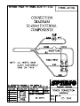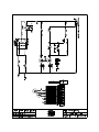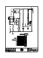
1
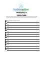
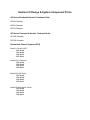
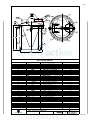
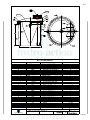
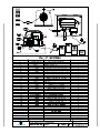
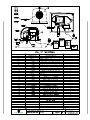
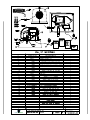
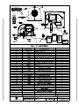
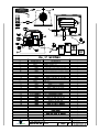
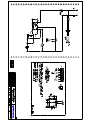
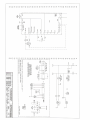
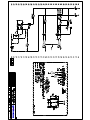
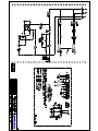
1
Table of Contents
Introduction
Plant Installation Instructions
Section 1.0 Off-loading/ Unpacking Instructions & Tank Installation
Section 2.0 OPS® (Operations/Control Center) Installation
Section 3.0 Anchored Diffuser Assembly Installation
Section 4.0 Hydro-Action® Air Pump
Section 5.0 OPS® Controls / Alarm System Testing
Section 6.0 Start-up Procedure
Section 7.0 Safety
Section 8.0 Installation Checklist
Section 9.0 Design & System Component Prints
Section 10.0 Electrical Schematics
Hydro-Action AP Series Wastewater Treatment Plant
The AP Series Aerobic Treatment Units
(ATUs) are now available through HydroAction®. Please read this introduction
before reviewing this manual.
Earth’s environment has purified water
through natural processes since the
beginning of time. Only recently, beginning
in the Twentieth Century, has man
developed a system to accelerate the
processes that Mother Nature uses. HydroAction® AP Series ATUs are just such
systems.
In 1916, the City of Houston, Texas, was
the first to use the activated sludge
wastewater treatment process as an
accepted, full-scale system process to purify
domestic wastewater. Since that time, the
United States and many other nations have
utilized this process and variations to
properly treat sewage. Federal Law 92-500
supports our nation’s commitment to
provide secondary treatment for all
domestic wastewater.
This commitment is presently being
extended to on-site sewage treatment
facilities. Hydro-Action® has been a visible
part of this effort since 1989. We have
manufactured numerous products to provide
individuals with a means of proper,
effective, efficient, and affordable on-site
wastewater treatment. Our professional
commitment to market needs and customer
service have enabled us to reach our goal
of providing effective products that assure a
safe, reusable effluent. We are helping
Mother Nature protect our environment and
our most valuable natural resource: water.
Our continuing mission is to develop and
manufacture individual on-site wastewater
treatment facilities that meet society’s needs
in the field. This manual is a part of that
dedication to customer service.
Hydro-Action® AP Series Aerobic
Treatment Units are among the most
advanced on-site products available today.
They are state-of-the-art extended aeration,
activated sludge wastewater treatment
facilities. The improvements in these units
make them not only extremely efficient
operational units but also the most easily
maintainable system in the industry.
By following the instructions in this manual,
you will be providing yourself with the best
on-site wastewater treatment and service.
We invite you to share in our pride of the AP
Series Treatment Units.
This manual includes information on the AP500, AP-600, AP-750, AP-1000G & AP1500G wastewater treatment plants. These
units may be installed with either a platform
mounted OPS® (operations/control center)
or a Remotely Located OPS®. Installation
needs vary, so your on-site wastewater
system may contain some of the following
auxiliary components along with the
treatment plant:
• Pretreatment tank
• Pump/holding tank
• Alarm systems
• Equipment for chosen effluent disposal
method (drip irrigation, spray irrigation,
gravel-filled drain field, pressure dosing,
etc.)
• Chlorinator / UV Disinfection Unit
The certified Hydro-Action® dealer or
installer of your Hydro-Action® AP Series
wastewater treatment plant is responsible
for completing and submitting to us the
Installation Warranty Information to properly
activate your Hydro-Action® Product
Warranty.
We are eager to assist you with any
questions or problems. Please contact
Hydro-Action® at 800.370.3749 to request
assistance from our Customer Service or
Engineering Departments
3
Off-Loading & Unpacking Instructions
Off-loading Instructions:
1. Insure that the system is un-strapped from the
delivery vehicle.
2. Mount the T-Bar assembly if Set-N-GoTM
System, otherwise insure proper off-loading by
means of forklift or machine capable of removing
without damage.
3. When system is off-loaded, inspect exterior
components for damage. Ops, Lids, tank, and
loose pallets should not have any evidence of
shipping damage.
4. Remove Covers for unpacking instructions.
Unpacking Instructions:
1. Remove all components that are shipped on
loose pallets.
2. Inventory components, and inspect for
damage during shipping. Pay special attention to
the diffusers, drops, and diffuser weights as they
are fragile and susceptible to shipping damage.
3. If a pump tank is included, inspect interior and
inventory components. Effluent pump, water
line, and wiring should all be intact and free of
defects.
4. Inspect Ops for any interior damage, and
check all connections to the control panel.
Vibration from shipping may cause wires and
airlines to become loose.
5. Close all covers and prepare tank to place
online.
Hydro-Action® AP SERIES
INSTALLATION INSTRUCTIONS:
To ensure proper installation of all components
of the Hydro-Action® AP Series wastewater
treatment plant, please read and follow all
instructions included in the following
sections. The AP Series WWTP with OPS®
must be installed according to these
instructions. Any modifications to the plant or
OPS® will result in loss of warranty and
invalidation of the plant’s NSF certification.
See Off-loading and Unpacking Instructions for
the Hydro-Action® AP Series WWTP from its
delivery means.
4
SECTION 1.0: Tank Installation
1.1: Locate plant in an area that provides good
ventilation and rainwater run-off. To decrease
the likelihood of hydraulic displacement (tank
flotation), choose a site that will minimize
possible groundwater saturation. Consider
seasonal water table and soil conditions in the
area of installation. Do not locate the plant in a
low spot in the ground where water tends to
pool or at the edge of any natural body of water.
If such a location cannot be avoided, call Hydro®
Action for technical advice. Prepare an
excavation with a width and a depth that will
allow any and all auxiliary tank inlets/ outlets to
align with the plant inlet/outlet. The plant access
cover should extend above the final surface
grade in such a way to prevent surface
watershed from entering the plant access riser.
Riser extensions may be required and are
added to provide adequate elevation for atgrade access. For plant dimensions see
drawings in Hydro-Action® O&M Manual.
1.2: Since the treatment plant must be level to
operate properly, using a transit leveling
instrument is recommended. If leveling
instrument is not available, a four (4) foot level
may be used. Use four (4) inches of sand or
fine-grained gradable material in the bottom
of the excavation to provide a solid flat base.
Be sure bottom of excavation is level before
lowering tanks.
1.3: When bottom of excavation is to grade,
smooth, tamped and level, gently place all
auxiliary tanks (if included) and plant into
excavation. While lowering treatment plant
into excavation, turn tank so four (4) inch
building outlet plumbing aligns with four (4) inch
inlet of treatment plant and the four (4)
inch treatment plant discharge line aligns with
effluent outfall plumbing.
1.4: The treatment plant and any other
associated tanks must be level to ensure proper
functioning. The connector pipe between any
and all tanks and plant should be between level
and one-eighth (1/8) inch per/foot-grade fall
toward plant outlet.
1.5: Once all tanks are level and properly
positioned, start filling them with clean water,
checking periodically for leaks. If a leak is
detected, stop filling and pump water level down
below leaking area and repair hole. When
leaking area has been repaired resume filling.
Continue this procedure until tanks are filled to
overflow and there are no leaks. During the
filling procedure, check periodically to make
certain tanks remain level.
1.6: While the tank is filling, run the incoming
sewage lines from a properly trapped and
vented building to the pretreatment tank first (if
used); then run plumbing from pretreatment
tank (if used) to the treatment plant tank inlet,
or from building directly to treatment plant tank.
Make sure that all plumbing meets building
codes. Also run the four (4) inch plant
outlet pipe to proper piping and/or equipment
to remove the treated effluent from the
immediate area. Once treatment tank is full and
leak free, make final connections to inlet and
outlet piping on plant.
plant installation could cause the tank to float.
Water sources may include rainfall, springs,
creeks, bayous, rivers, lakes, and coastal areas.
Proper precautions are therefore required to
prevent tank flotation due to hydraulic
displacement.
®
1.7: Hydro-Action OPS® (operations/control
center) installation can be accomplished at this
time. Follow the instruction given in section 2.0,
OPS® (Operations/Control Center) Installation.
• Whenever a tank is pumped, do not remove
more than one-half of the capacity of the
tank. It is recommended that you pump the
tank during dry seasons only. However, if
tank must be pumped during the wet
season, watch for upward movement of the
tank while pumping is being done. If upward
movement is detected during pumping,
immediately stop pumping water out of
the tank and refill the tank to stop
flotation. Each site must be evaluated on
a case by case basis to determine the best
time to remove water from the tank and
prevent flotation.
1.8: Hydro-Action ® diffuser assembly
installation can be accomplished at this time.
Follow the instructions given in section 3.0,
Anchored Diffuser Assembly Installation.
1.9: For installation below normal grades
Hydro-Action®s’ twenty-four (24)
inch (20” for models AP-1000G and AP-1500G)
diameter extension riser(s) must be used to
bring access above grade. Riser must be above
grade to provide plant ventilation. Extension
risers on AP Series units may be any
reasonable depth. Under no circumstances shall
the cover be buried. If installing Platform
Mounted OPS®, add an equal number of OPS®
base risers to bring it to the same grade as the
access risers.
1.10: After all tanks and plant have been filled
to outlet overflow, backfill the excavation using
a material that will settle well around the tanks.
Do not use large rocks or heavy clay. Place the
material around the tanks in layers, tamping
and watering each layer.
1.11: Before installation is complete, the access
cover and the Platform Mounted OPS®
enclosure must be in place and the tamperresistant screws, provided by Hydro-Action®,
must be installed and properly tightened to
prevent unauthorized personnel from gaining
entry inside plant.
Note: Any tank and plant must be filled to
overflow with water during and after installation
to prevent hydrostatic displacement (floating of
tanks).
Hydraulic displacement and tank flotation may
occur whenever water and solids are removed
from the tank when high groundwater conditions
exist. Any source of water in the soil around the
These precautions include, but are not limited
to, the following:
• Plant location — choose a site that will
minimize possible groundwater saturation
(see Section 1.1).
SECTION 2.0: OPS®
(Operations/Control Center) Installation
2.1: Following are all parts needed to complete
the installation of model AP-500, AP-600, AP750, AP-1000G, and AP-1500G WWTP using
the Platform Mounted or Remotely Located
OPS®. Should any part(s) be missing or off
specification, or if you encounter any problems
in completion of installation of the unit or with the
®
above listed parts, call the Hydro-Action
Customer Service Department at
800.370.3749 for assistance.
Item:
Quantity
1. AP Series Class I Aerobic WWTP ..…… 1 ea.
2. AP Series Hydro-Action® air pump…...... 1 ea.
3. Airline seal gasket, 1” diameter .............. 1 ea.
4. Air diffuser assembly w/4 sm. diffusers... 2 ea.
5. Airline drops, std. Length................…..... 2 ea.
6. Airline drops extension(s) ..…………...... 2 ea.
7. Airline drops retainer clamp.......….......... 2 ea.
8. Airline drops anchor ............................... 2 ea.
9. Electrical enclosure ................................ 1 ea.
10. Air pressure-tubing kit .......................... 1 ea.
11. Effluent Tee assembly, 4” diameter ..… 1 ea.
12. High-level alarm float ........................... 2 ea.
13. Unilet and coupling, ½” diameter.......… 1 ea.
®
14. OPS enclosure ................…................ 1 ea.
5
15. OPS® base screws, 7” long ....……...... 3 ea.
16. PVC airline header, ½” with fittings....... 1 ea.
17. Remote alarm box (optional)................. 1 ea.
2.4.1: Glue 5 5/8”-long ½” PVC pipe to 90degree PVC fitting that is connected to air
pump.
2.1.1: The parts listed above include all the
parts necessary for completion of the HydroAction® AP Series Class I Aerobic WWTP. By
following these simple instructions, your
assembly of the AP Series unit will be completed
in minimum time and with assurance of a
properly functional unit.
2.4.2: Connect electrical jacketed SO cables
from high-level float in plant and floats and
pump (if included) in pump tank by using
fishwire to pull cables through conduit into base
®
of OPS enclosure and up through sealing
assemblies. Conduit from pump tank to plant
should enter plant in the riser assembly above
the access, either directly above outlet or above
clarification compartment. This keeps SO cables
from interfering with removal of anchored
diffuser assemblies. Connect cables through
compression fitting into electrical enclosure as
shown on electrical schematics for each model
(see Hydro-Action® O&M Manual).
Note: Electrical schematics are included inside
each electrical enclosure and must remain in
this location at all times to ensure that system
is in compliance with required rules of
certification.
2.2: The AP-500, AP-600 and AP-750 plant
may be installed with either a Platform Mounted
®
®
OPS or Remotely Located OPS . The parts
provided assume a typical installation. If site
conditions are not normal and additional parts
are necessary for correct installation, be sure
that you have all necessary additional parts
before beginning installation of the AP Series
unit. The AP-1000G and AP-1500G use the
remotely located OPS®. Additional parts may
include access risers and equipment base
risers, flexible airline hose extensions, electrical
wiring, conduit, PVC pipe, and other items.
2.3: Properly install the AP Series WWTP in
the chosen site being sure that the plant is level
and backfilled correctly. Assemble all the
component parts per instructions in section 1.0,
Tank Installation. Make all necessary hose
connections, wiring connections, pipe
connections, and alarm connections prior to
testing with electrical power. If installing a
®
Platform Mounted OPS that has been factory
mounted, OPS® is pre-installed on top of tank.
Note: Whenever riser extensions are added to
bring the Platform Mounted OPS® base and
plant access cover to grade, remember to
provide enough length to all piping and wiring
to meet the needs of raised installation.
2.4: If installing a Platform Mounted OPS® that
has been shipped separately, remove OPS®
enclosure and glue 5 5/8”-long ½” PVC pipe
into airline coupling on platform. Set OPS® base
on top of platform aligning airline hole with ½”
PVC pipe. Align vapor and moisture sealing
assemblies on OPS® base with pre-drilled
gasketed holes in platform and push the vapor
and moisture sealing assemblies through
holes in platform. Be sure base is centered on
platform before proceeding. Attach base to
platform using three seven (7) inch screws; two
of the screws will replace smaller screws
holding air pump to OPS® base during shipping.
Place the third screw at marked location (near
corner of OPS® even with vapor and moisture
sealing assemblies). Be sure to drill screws
straight down.
6
Do not remove the schematic from electrical
enclosure.
2.5: Run electrical power in conduit from main
®
supply to OPS base. Thread wiring through
base and into OPS® enclosure. Make
connections through 3-wire compression fitting
into electrical enclosure.
2.6: Electrical power connection to electrical
controls in electrical enclosure is made by
connecting the wiring to the electrical controls
as shown in the electrical controls instructions.
See Hydro-Action® O&M Manual.
2.7: An optional remote alarm may be mounted
on the exterior of a house or garage, if desired.
This alarm is equipped with audible and visible
alarms.
2.8: When required, OPS® risers can be
stacked below OPS® base. The OPS®
enclosure is attached by four security screws.
Do not kink cables inside OPS® when attaching
the enclosure.
2.9: If the Remotely Located OPS® is being
installed, the OPS® enclosure simply sits on top
of a polyethylene base located away from the
plant (no more than 55 feet from plant location).
SECTION 3.0: Anchored Diffuser Assembly
Installation
3.1: Remove anchored diffuser assemblies with
attached flexible air hoses from OPS® shipping
box or OPS® enclosure.
Note: Before installing flexible air hoses with
anchored diffuser assemblies, air hoses and
plant air header must be purged of all debris.
This is accomplished by turning air pump on
for a few minutes. Air hoses must be free of
debris to ensure proper operation of the
diffusers, check valve, and aeration system.
3.2: Connect air hose to air header tee by
pushing hose securely onto barb fitting. Lower
anchored diffuser assembly to bottom of
aeration compartment through access opening.
3.3: Lift anchor a few inches off tank bottom
and bring air hose into retainer clamp. Steady
diffuser assembly and lower it to tank bottom,
making sure that diffuser assembly rests outside
circumference of access riser. See plant detail
drawings. Secure retainer clamp. Allow
minimum slack in the air hose. The air hose
should not be supporting the anchor. When
correctly installed, the anchor rests on the
bottom of the tank with a light tension on the
attached air hose at the point of the retainer
clamp.
Note: Diffuser stones are to be replaced on
the AP Series plants whenever the pressure
reading at the Schrader valve on the discharge
side of the air pump equals or exceeds a
reading of 3.5 psig.
SECTION 4.0: Hydro-Action® Air Pump
4.1: Hydro-Action® air pump models are
preinstalled in the OPS® (operations/control
center). See section 2.0 for instructions on
making electrical and airline connections to the
air pump.
®
4.2: Located in Hydro-Action O&M Manual is a
copy of Operation & Maintenance Technical
Manual for Hydro-Action® Air Pumps. It is
recommended that you review this data, which
includes important information for
troubleshooting, operating, and maintaining the
air pump.
SECTION 5.0: OPS® Controls/Alarm System
Testing
5.1: The alarms supplied with this wastewater
treatment plant provide the owner with a secure,
reliable, dependable, and economical means
of notification for most malfunctions of the plant
that would lead to producing an unsatisfactory
effluent. These alarms include notification for
problems of air pump failure, aeration piping
malfunctions, and high water level. These
alarms need to be inspected and tested after
installation and during each plant operation and
maintenance site visit. If an optional remote
alarm has been installed, it should also be
inspected and tested during each site visit.
5.2: To determine which model of OPS® is
being used, see model number on outside of
OPS® enclosure (example: OPS® model 5020). To gain access to the electrical controls and
air pump, remove the security screws holding
the OPS® enclosure to the base. Remember
that each model offers different control and
alarm functions.
5.3: The switch indicated “normal/silence” on
OPS® models 50-11, 50-20, 50-30, &
50-32 is used to test the alarms, silence an
alarm condition, or is left in the normal on
position. The normal position of the mode is
for normal operation of the plant and silence
is a mode that will disrupt the alarm horn.
Move the switch to the left and hold to
test the alarm. The switch will reset itself
automatically.
5.4: Test the low air pressure alarm. This alarm
will be activated whenever the air pump fails to
provide sufficient air to the diffuser assembly.
To test this alarm, remove the air tubing from
the barbed fitting on the electrical enclosure.
This loss of air pressure should cause the alarm
to signal. Silence the alarm and return the air
pressure tubing to original position. Another
simple check is to turn off the air pump
momentarily; the loss of air pressure should
cause the alarm to signal. If the alarm is not
activated whenever air pressure is low, check
alarms and replace light bulb or audible horn
as required.
5.5: Test the plant’s high-level float switch and
alarm. If the system also includes a pump/
holding tank to remove effluent, the HydroAction® electrical controls can be equipped with
a second high-level alarm. Test one or both of
these alarms by manually raising each float and
holding it up until you can see and hear the
alarms.
5.6: If installing OPS® models 50-30 set the
timer. The timer setting is covered in the O&M
manual. Please reference the timers section of
this manual for correct timer specifications.
SECTION 6.0: Start-up Procedure
6.1: Initial start-up of the AP Series WWTP is
very simple. No special procedures are required
for bringing the plant online. The unit should
be full of water from earlier leak testing. After
7
installation and checkout of the component
parts, all that is required for start-up is to turn
on electrical power and inform the owner that
the plant is operational and he or she may
commence use. There is no need to seed the
plant.
or chlorine tablets.
• Always wash with soap and water after
handling any contaminated item. The use
of good bactericide soap is strongly
recommended.
6.2: If the unit is to remain idle for a period of
time, please inform the owner that the unit is
operational and that the only requirement for
starting the plant is to turn on electrical power
and begin using the facilities. If any mechanical
or electrical problems are experienced when
attempting start-up, the owner should call the
dealer for service and assistance in start-up of
the plant.
• Always dispose of scum, rags, trash,
debris, or soiled material in a proper
waste container.
SECTION 7.0: Safety
• Treated effluent from a Hydro®
Action or other treatment unit may still
contain harmful microorganisms. Careful
attention must be used when dealing with
any form of wastewater or effluent.
7.1: Safety is an important issue in our business
since we deal with one of the more potentially
health hazardous materials known: raw
sewage. Domestic wastewater carries in it
members of a specialized group of life known
as microorganisms. Such microorganisms are
bacteria, viruses, algae, actinomycetes,
protozoa, fungi, rotifers, crustaceans, and other
members of both the plant and animal worlds.
The function of a wastewater treatment plant is
to treat the water to a degree that the effluent is
relatively free of pathogenic bacteria and
nuisance microorganisms. Until the wastewater
entering the plant has had sufficient time for
treatment and disinfection, it may contain any
number of the harmful organisms that cause
disease.
7.2: As raw wastewater may and usually does
contain some level of unsafe microorganisms,
proper respect and care must be given to safety.
When coming into contact with raw sewage,
do not fear the contact, but do take proper
precautions to avoid potential danger.
7.3: Follow these simple safety precautions
whenever exposed to wastewater:
• Wear disposable rubber gloves when
handling wastewater contaminated items
8
• If a wastewater spill or leak occurs in a
yard, flush area with plenty of clean
water and disinfect. If a spill or leak
occurs in the house, clean with a dilute
solution of bleach.
• If an illness or disease is suspected to
have come from exposure to sewage,
get proper medical attention immediately.
When proper treatment is given the remedy
and cure will be rapid and less of a problem.
There are some serious diseases that could
be transmitted by contact with raw sewage
-take the proper precautions and be safe!
• Report all accidents relating to sewage
exposure to the proper supervisory
personnel.
*Note: Homeowner should be advised of
all safety and operation of their new
Hydro-Action® system.
AK/HA Manufacturing, LLC
Installation Checklist
Hydro-action Industries' aerobic treatment systems should be serviced at least every six months
per NSF requirements. Please consult the Installation Manual while performing this checklist.
Chose site and soil condition, excavate
notes:
Install gradeable material and level system
notes:
Fill tanks with water and leak check while buring
notes:
Connect inlet and discharge piping
notes:
Install OPS as per instructions and run power conduit
notes:
Install diffuser assemblies
notes:
Install OPS and Tank Covers w/ supplied security screws
notes:
Follow start-up procedure and educate homeowner on their system
notes:
Perform system check to insure proper operation
notes:
Fill out installation / warranty sheet
notes:
Give copy of homeowners manual to homeowner
notes:
Give homeowner copy of service contract and warranty sheet
notes:
Send in installation warranty sheet to Manufacturer
notes:
Section 9.0 Design & System Component Prints
AP Series Residential Aerobic Treatment Units
AP500 Complete
AP600 Complete
AP750 Complete
AP Series Commercial Aerobic Treatment Units
AP1000 Complete
AP1500 Complete
Operational Control Systems (OPS)
Model 11 Gravity OPS
100L Model
150L Model
1/4R Model
3/4R Model
Model 20 On Demand
100L Model
150L Model
1/4R Model
3/4R Model
Model 30 24Hr Timed
100L Model
150L Model
1/4R Model
3/4R Model
Model 32 Micro-dosed Timed
100L Model
150L Model
1/4R Model
3/4R Model
10/13
J-J2
K-K5
H1-H3
I-I1
A2
A4-A8
B
C
Ø73
Ø66
3/4"
A D A P T -X A
EL-F
F- A
TP
- X
LE
S
A DA
I ND U S T R
IE
7
Ø24 8
D
F
AK
D
E
G
AD A PT- A
A3
I ND U S T R
S
A PT- A - F
-F
LE
X
AK
AD
X
LE
IE
64
1
Ø24 2
A
3/4"
I
A1
H
AK
70 1
4
3/4"
Ø76
Ø70
66
BILL OF MATERIALS
ITEM
P/N
HA-AP500-P
QTY:
DESCRIPTION
AP500, W/ PLATFORM COMPLETE
1
A1
180075
TANK, BODY AP500-P
1
A2
180080
DOME, AP500-P RTM
1
A3
240050
CONE, POLY AP500
200095
SCREW, 5/16" X 2" HWH SDS 410
A5
760068
BOLT, 3/8"-16 X 1 1/2" TAMPERPROOF
A6
200013
NUT, 3/8"-16 SS
A7
200006
WASHER, 3/8" STD SS
A8
160030
CONSEAL, 3/8" X 1"
A4
1
29
2
2
4
1 ROLL
B
120001
ASSEMBLY, EYEBOLT
C
100065-35
PIPE STUB, PLUMBING & CONNECTING SCH35
1
D
240062
GROMMET, 4"
2
E
100010
GROMMET, 4" DUAL TITE
1
F
100103-35
ASSEMBLY, TEE AP SERIES OUTLET SCH35
1
G
100067-35
PIPE STUB, OUTLET AP500 SCH35
1
H
100058-3DRP
ASSEMBLY, DIFFUSER 3 DROP
H1
H2
H3
180103
ELL, .50 90° PVC SCH40
1
240058
GROMMET, 1/2" ADAPT-A-FLEX
1
200059
AKR30505
J2
HYDRO-ACTION, PLATFORM DARK GREEN
1
SCREW, 1.50" X #12 SELF-TAPPING
4
1
SCREW, 1" #10 SELF-TAP PPH SS
6
CONSEAL, 1/2" X 21'
LID, TANK RISER 24"
241024
K
(1) 5" LONG
RISER, TANK 24" X 6" PL
241022
J
J1
1
PIPE, .50 PVC SCH40
200094
I1
ADAPT-A-FLEX SCH35
180114
AKC10052-A
I
2
.333
PL
1
200070
SCREW, 1 1/2" TRIGROOVE SM
4
K2
N/A
SCREW, LID (SUPPLIED W/LID)
4
K3
120000
ASSEMBLY, MUSHROOM CAP
1
K4
760050
TAG, SERIAL NUMBER AP500
1
K5
200025
RIVET, 1/8" GRIP 1/8" DIA. POP
4
K1
N/A
1 TUBE
SIKAFLEX
AP500 W/PLATFORM COMPLETE
hydro action
green from the ground up
APPROVED BY:
R
SIGNATURE
DRAWN BY: A.DAVIS
PART#
REV.
DATE:
APPROVED
1/31/13
4
HA-AP500-P
Page 101
10/13
J-J2
H1-H2
I-I1
Ø73
K-K5
Ø66
A1
A3-A7
B
Ø24 7
8
C
D
F
AD A PT- A
-F
X
LE
E
Ø24 21
G
A
3/4"
AK
D
I
A2
70 1
4
64
Ø76
Ø70
A
H
66
BILL OF MATERIALS
ITEM
P/N
QTY:
DESCRIPTION
AP600, W/ PLATFORM COMPLETE
AP600-P
1
A
180076
TANK, BODY AP600-P
1
A1
180030
DOME, AP600-P
1
A2
180041
CONE, FIBERGLASS AP600
A3
200095
SCREW, 5/16" X 2" HWH SDS 410
1
33
A4
760068
BOLT, 3/8"-16 X 1 1/2" TAMPERPROOF
2
A5
200013
NUT, 3/8"-16 SS
2
A6
200006
WASHER, 3/8" STD SS
A7
160030
CONSEAL, 3/8" X 1"
ASSEMBLY, EYEBOLT
120001
B
4
1 ROLL
2
C
100065-35
PIPE STUB, PLUMBING & CONNECTING SCH35
1
D
240062
GROMMET, 4"
2
100010
E
100103-35
F
100068-35
G
100058-3DRP
H
ADAPT-A-FLEX SCH35
GROMMET, 4" DUAL TITE
1
ASSEMBLY, TEE AP SERIES OUTLET SCH35
1
PIPE STUB, OUTLET AP600 SCH35
1
ASSEMBLY, DIFFUSER 3 DROP
1
H1
180114
PIPE, .50 PVC SCH40
H2
240058
GROMMET, 1/2" ADAPT-A-FLEX
I
AKC10052-A
HYDRO-ACTION, PLATFORM DARK GREEN
1
I1
200094
SCREW, 1.50" X #12 SELF-TAPPING
4
J2
K
K1
RISER, TANK 24" X 6" PL
1
SCREW, 1" #10 SELF-TAP PPH ZINC
6
AKR30505
CONSEAL, 1/2" X 21'
241024
LID, TANK RISER 24"
200070
SCREW, 1 1/2" TRIGROOVE SM
4
N/A
SCREW, LID (SUPPLIED W/LID)
4
ASSEMBLY, MUSHROOM CAP
1
K2
120000
K3
1
200059
241022
J
J1
(1) 5" LONG
.333
PL
1
K4
160018
TAG, SERIAL NUMBER AP600
1
K5
200025
RIVET, 1/8" GRIP 1/8" DIA. POP
4
N/A
SIKAFLEX
1/4 TUBE
AP600 W/PLATFORM COMPLETE
hydro action
green from the ground up
APPROVED BY:
R
SIGNATURE
DRAWN BY: A.DAVIS
PART#
REV.
DATE:
APPROVED
08/27/13
7
HA-AP600-P
Page 102
10/13
J-J2
H1-H2
K-K5
A2
I-I1
Ø79
A4-A8
B
E
C
D
Ø24 7
8
D
F
G
A3
1
Ø24 2
64
A
I
A1
AK
70 41
Ø72
H
Ø82
Ø76
72
BILL OF MATERIALS
ITEM
P/N
HA-AP750-P
QTY:
DESCRIPTION
AP750, W/ PLATFORM COMPLETE
1
A1
180077
TANK, BODY AP750-P
1
A2
760070
DOME, AP750-P RTM
1
A3
180042
CONE, FIBERGLASS AP750
A4
200095
SCREW, 5/16" X 2" HWH SDS 410
1
34
A5
760068
BOLT, 3/8"-16 X 1 1/2" TAMPERPROOF
2
A6
200013
NUT, 3/8"-16 SS
2
A7
200006
WASHER, 3/8" STD SS
A8
160030
CONSEAL, 3/8" X 1"
2
2 ROLL
B
120001
ASSEMBLY, EYEBOLT
C
100065-35
PIPE STUB, PLUMBING & CONNECTING SCH35
1
D
240062
GROMMET, 4"
2
E
100010
GROMMET, 4" DUAL TITE
1
F
100103-35
ASSEMBLY, TEE AP SERIES OUTLET SCH35
1
G
100069-35
PIPE STUB, OUTLET AP750 SCH35
1
H
100058-3DRP-750
ASSEMBLY, DIFFUSER 3 DROP AP750
180114
H1
240058
H2
AKC10052-A
I
200094
I1
200059
AKR30505
J2
1
PIPE, .50 PVC SCH40
(1) 5" LONG
GROMMET, 1/2" ADAPT-A-FLEX
1
HYDRO-ACTION, PLATFORM DARK GREEN
1
SCREW, 1.50" X #12 SELF-TAPPING
4
1
SCREW, 1" #10 SELF-TAP PPH ZINC
6
CONSEAL, 1/2" X 21'
LID, TANK RISER 24"
241024
K
ADAPT-A-FLEX SCH35
RISER, TANK 24" X 6" PL
241022
J
J1
2
.333
PL
1
200070
SCREW, 1 1/2" TRIGROOVE SM
4
K2
N/A
SCREW, LID (SUPPLIED W/LID)
4
K3
120000
ASSEMBLY, MUSHROOM CAP
1
K4
160019
TAG, SERIAL NUMBER AP750
1
K5
200025
RIVET, 1/8" GRIP 1/8" DIA. POP
4
K1
N/A
1/4 TUBE
SIKAFLEX
AP750 W/PLATFORM COMPLETE
hydro action
green from the ground up
APPROVED BY:
R
SIGNATURE
DRAWN BY: A.DAVIS
PART#
REV.
DATE:
APPROVED
04/22/13
5
HA-AP750-P
Page 103
10/13
I-I2
J-J5
A4-A8
5
Ø82 8
A2
B
K-K1
C
L-L1
Ø21
D
D
F
E
1
8
Ø20 3
4
G
A3
70"
H-H2
A1
A
AK
I
Ø79 5
8
5
Ø85 8
66
BILL OF MATERIALS
ITEM
P/N
HA-AP1000-P
QTY:
DESCRIPTION
AP1000, W/ PLATFORM COMPLETE
1
A1
180038
TANK, BODY AP1000-P
1
A2
180032
DOME, AP1000-P
1
A3
180043
CONE, POLY AP1000
A4
200095
SCREW, 5/16" X 2" HWH SDS 410
1
28
A5
760068
BOLT, 3/8"-16 X 1 1/2" TAMPERPROOF
2
A6
200013
NUT, 3/8"-16 SS
2
A7
200006
WASHER, 3/8" STD SS
A8
160030
CONSEAL, 3/8" X 1"
ASSEMBLY, EYEBOLT
120001
B
2
2 ROLL
2
C
100065-35
PIPE STUB, PLUMBING & CONNECTING SCH35
1
D
240062
GROMMET, 4"
2
100010
E
100103-35
F
100070-35
G
100058-3DRP-1000
H
180114
H1
ADAPT-A-FLEX SCH35
GROMMET, 4" DUAL TITE
1
ASSEMBLY, TEE AP SERIES OUTLET SCH35
1
PIPE STUB, OUTLET AP1000 SCH35
1
ASSEMBLY, DIFFUSER AP1000 3 DROP
1
PIPE, .50 PVC SCH40
(1) 5" LONG
H2
240058
GROMMET, 1/2" ADAPT-A-FLEX
I
241023
RISER, TANK 20" X 6" PL
I1
200059
SCREW, 1" #10 SELF-TAP PPH ZINC
I2
AKR30505
CONSEAL, 1/2" X 21'
J
241025
LID, TANK RISER 20"
J1
200070
SCREW, 1 1/2" TRIGROOVE SM
8
J2
N/A
SCREW, LID (SUPPLIED W/LID)
4
J3
120000
ASSEMBLY, MUSHROOM CAP
1
J4
760050
TAG, SERIAL NUMBER AP1000
1
J5
200025
RIVET, 1/8" GRIP 1/8" DIA. POP
4
K1
240058
240058
L1
.667
PL
1
1
GROMMET, 1/2" ADAPT-A-FLEX
1
ASSEMBLY, COMMERCIAL AIRLINE
100080
L
1
12
ASSEMBLY, FLOAT COMMERCIAL
100075
K
1
N/A
1
GROMMET, 1/2" ADAPT-A-FLEX
1
SIKAFLEX
1/4 TUBE
AP1000 W/PLATFORM COMPLETE
hydro action
green from the ground up
APPROVED BY:
R
SIGNATURE
DRAWN BY: A.DAVIS
PART#
REV.
DATE:
APPROVED
08/27/13
6
HA-AP1000-P
Page 104
10/13
J-J2
K-K5
A3-A8
B
A1
Ø91
I-I1
12
C
L-L1
Ø82
FLOW LINE
Ø21 81
D
F
D
G
Ø20 3
4
25
E
92
81 21
80
A
3/4"
AK
I
Ø75
A2
Ø94
H
Ø88
11
A
87 1
2
BILL OF MATERIALS
ITEM
P/N
HA-AP1500G
180040
TANK, BODY AP1500
180053
DOME, AP1500
A
A1
QTY:
DESCRIPTION
AP1500G, SYSTEM COMPLETE
1
1
1
180045
CONE, FIBERGLASS AP1500G
A3
200095
SCREW, 5/16" X 2" HWH SDS 410
A4
760068
BOLT, 3/8"-16 X 1 1/2" TAMPERPROOF
2
A5
200013
NUT, 3/8"-16 SS
2
A6
200006
WASHER, 3/8" STD SS
A8
160032
CONSEAL, 3/8" X 1 1/2"X 8'
A2
2
3 1/4 ROLLS
ASSEMBLY, EYEBOLT
B
120001
C
100065-35
240062
D
100010
E
2
PIPE STUB, PLUMBING & CONNECTING SCH35
GROMMET, 4"
1
ADAPT-A-FLEX SCH35
2
GROMMET, 4" DUALTITE
ASSEMBLY,
100103-35
F
1
30
1
TEE AP SERIES OUTLET SCH35
1
G
100073-35
PIPE STUB, OUTLET AP1500 SCH35
1
H
100058-3DRP
ASSEMBLY, DIFFUSER AP1500 3 DROP
1
I
100075
ASSEMBLY, FLOAT
1
COMMERCIAL
240058
GROMMET, 1/2" ADAPT-A-FLEX
1
241023
RISER, TANK 20" X 6" PL
2
J1
200059
SCREW, 1" #10 SELF-TAP PPH ZINC
J2
AKR30505
CONSEAL, 1/2" X 21'
241025
LID, TANK RISER 20"
200070
SCREW, 1 1/2" TRIGROOVE SM
8
N/A
SCREW, LID (SUPPLIED W/LID)
8
I1
J
K
K1
K2
K3
16
1.334
PL
2
ASSEMBLY, MUSHROOM CAP
120000
2
K4
160010
TAG, SERIAL NUMBER AP1500
1
K5
200025
RIVET, 1/8" GRIP 1/8" DIA. POP
4
ASSEMBLY, COMMERCIAL AIRLINE
100080
L
240058
L1
1
GROMMET, 1/2" ADAPT-A-FLEX
1
N/A
SIKAFLEX
N/A
RISER STICKER
1
N/A
CHECK PRODUCT STICKER
1
1/4 TUBE
AP1500G, SYSTEM COMPLETE
hydro action
green from the ground up
R
DRAWN BY: A.DAVIS
APPROVED
APPROVED BY:
SIGNATURE
DATE:
09/13/13
REV.
PART#
7
HA-AP1500G
Page 105
I
G-G6
E-E4
C-C3
D
hydro action
R
green from the ground up
F-F2
MANUAL
AIR PUMP
MANUAL
WATER
PUMP
*IF
ORDERED*
MANUAL
OWNER
AP-SERIES
B-B4
WARRANTY
CARD
A
BILL OF MATERIALS
P/N
ITEM
HA-EC50-11-L-100
A
240026-GREEN
B
200033
DESCRIPTION
QTY:
OPS, EC50-11-LINEAR 100
1
BASE, OPS 6" PLATFORM RISER- GREEN
1
ASSEMBLY, CONDUIT 1 1/4"
1
B1
180129
ADAPTER, FEMALE 1-1/4" PVC (TXS)
1
B2
700039
COUPLING, 1-1/4" CONDUIT PVC (SXS)
1
B3
180130
ELBOW, 1.25 SWEEPING PVC CONDUIT SCH80
1
B4
240053
FITTING, 1-1/4 (6) HOLE CORD GRIP
1
C
100122
PUMP, AIR LINEAR 100
1
C1
200067
STRAPPING, 3/4" X 10'
(2) 3 1/2" INCHES
C2
200059
SCREW, 1" #10 SELF TAP PPH ZINC
2
C3
200051
WASHER, 1" x #10 FENDER
2
D
120129-L
E
122126
KIT, AIR PRESSURE SWITCH LINEAR
1
PANEL, 50-11
1
E1
200116
BRACKET, 5" X 11" SLOTTED
2
E2
200059
SCREW, 1" #10 SELF TAP PPH ZINC
4
E3
200102
SCREW, THUMB 1/4"-20 X 3/8"
2
E4
200056
WASHER, 5/16" BONDED SS
2
200050
F
F1
ASSEMBLY, CONDUIT OPS POWER SUPPLY
100213
F2
700036
HA-240027-H-GREEN
G
1
PIPE, 3/4" CONDUIT BEND
(1) 10 1/8" LONG
COUPLING, 3/4" CONDUIT
2
COVER, OPS & AIR PUMP KIT W/ HOLES
1
G1
200025
RIVET, 1/8" GRIP 1/8" DIA. POP
G2
760059
TAG, NORMAL SILENCE OPS
1
G3
200036
SCREW, 7" #12 ROOF GRIP
4
G4
200082
WASHER, #10 COMMON FLAT SS
4
G5
200069
SCREW, 1/2" #10-24 TRIGROOVE
4
G6
200051
WASHER, 1" X #10 FENDER
4
4
WARRANTY CARD W/ SALES ORDER
1
OWNERS MANUAL
1
AIR PUMP MANUAL
1
WATER PUMP MANUAL (IF ORDERED)
1
OPS, EC50-11-LINEAR 100
hydro action
green from the ground up
DRAWN BY: A.DAVIS
PART#
R
APPROVED BY: STEVE DAVIS
SIGNATURE
DATE:
8/20/10
REV.
1
HA-EC50-11-L-100
I
G-G6
E-E4
C-C3
D
hydro action
R
green from the ground up
F-F2
MANUAL
AIR PUMP
MANUAL
WATER
PUMP
*IF
ORDERED*
MANUAL
OWNER
AP-SERIES
B-B4
WARRANTY
CARD
A
BILL OF MATERIALS
P/N
ITEM
HA-EC50-11-L-150
A
240026-GREEN
B
200033
DESCRIPTION
QTY:
OPS, EC50-11-LINEAR 150
1
BASE, OPS 6" PLATFORM RISER- GREEN
1
ASSEMBLY, CONDUIT 1 1/4"
1
B1
180129
ADAPTER, FEMALE 1-1/4" PVC (TXS)
1
B2
700039
COUPLING, 1-1/4" CONDUIT PVC (SXS)
1
B3
180130
ELBOW, 1.25 SWEEPING PVC CONDUIT SCH80
1
B4
240053
FITTING, 1-1/4 (6) HOLE CORD GRIP
1
C
100124
PUMP, AIR LINEAR 150
1
C1
200067
STRAPPING, 3/4" X 10'
(2) 3 1/2" INCHES
C2
200059
SCREW, 1" #10 SELF TAP PPH ZINC
2
C3
200051
WASHER, 1" x #10 FENDER
2
D
120129-L COMM
E
122126
KIT, AIR PRESSURE SWITCH 3/4" COMMERCIAL
1
PANEL, 50-11
1
E1
200116
BRACKET, 5" X 11" SLOTTED
2
E2
200059
SCREW, 1" #10 SELF TAP PPH ZINC
4
E3
200102
SCREW, THUMB 1/4"-20 X 3/8"
2
E4
200056
WASHER, 5/16" BONDED SS
2
200050
F
F1
ASSEMBLY, CONDUIT OPS POWER SUPPLY
100213
F2
700036
HA-240027-H-GREEN
G
1
PIPE, 3/4" CONDUIT BEND
(1) 10 1/8" LONG
COUPLING, 3/4" CONDUIT
2
COVER, OPS & AIR PUMP KIT W/ HOLES
1
G1
200025
RIVET, 1/8" GRIP 1/8" DIA. POP
G2
760059
TAG, NORMAL SILENCE OPS
1
G3
200036
SCREW, 7" #12 ROOF GRIP
4
G4
200082
WASHER, #10 COMMON FLAT SS
4
G5
200069
SCREW, 1/2" #10-24 TRIGROOVE
4
G6
200051
WASHER, 1" X #10 FENDER
4
4
WARRANTY CARD W/ SALES ORDER
1
OWNERS MANUAL
1
AIR PUMP MANUAL
1
WATER PUMP MANUAL (IF ORDERED)
1
OPS, EC50-11-LINEAR 150
hydro action
green from the ground up
DRAWN BY: A.DAVIS
PART#
R
APPROVED BY: STEVE DAVIS
SIGNATURE
DATE:
8/20/10
REV.
1
HA-EC50-11-L-150
I
G-G6
E-E4
C-C3
hydro action
D
R
green from the ground up
D1,D2
F-F2
MANUAL
AIR PUMP
MANUAL
WATER
PUMP
*IF
ORDERED*
MANUAL
OWNER
AP-SERIES
B-B4
WARRANTY
CARD
A
BILL OF MATERIALS
P/N
ITEM
HA-EC50-11-RV-.25
A
240026-GREEN
B
200033
DESCRIPTION
QTY:
OPS, EC50-11-RV-.25
1
BASE, OPS 6" PLATFORM RISER- GREEN
1
ASSEMBLY, CONDUIT 1 1/4"
1
B1
180129
ADAPTER, FEMALE 1-1/4" PVC (TXS)
1
B2
700039
COUPLING, 1-1/4" CONDUIT PVC (SXS)
1
B3
180130
ELBOW, 1.25 SWEEPING PVC CONDUIT SCH80
1
B4
240053
FITTING, 1-1/4 (6) HOLE CORD GRIP
1
121068
C
PUMP, AIR ROTARY VANE 1/4HP
1
C1
200067
STRAPPING, 3/4" X 10'
(2) 17" INCHES
C2
200059
SCREW, 1" #10 SELF TAP PPH ZINC
4
C3
200051
WASHER, 1" x #10 FENDER
4
KIT, AIR PRESSURE SWITCH 1/2" STD RV
1
D
120139-RV
E
122126
PANEL, 50-11
1
E1
200116
BRACKET, 5" X 11" SLOTTED
2
E2
200059
SCREW, 1" #10 SELF TAP PPH ZINC
4
E3
200102
SCREW, THUMB 1/4"-20 X 3/8"
2
E4
200056
WASHER, 5/16" BONDED SS
2
122126
F
F1
ASSEMBLY, CONDUIT OPS POWER SUPPLY
200050
F2
700036
HA-240027-H-GREEN
G
1
PIPE, 3/4" CONDUIT BEND
(1) 10 1/8" LONG
COUPLING, 3/4" CONDUIT
2
COVER, OPS & AIR PUMP KIT W/ HOLES
1
G1
200025
RIVET, 1/8" GRIP 1/8" DIA. POP
G2
760059
TAG, NORMAL SILENCE OPS
1
G3
200036
SCREW, 7" #12 ROOF GRIP
4
G4
200082
WASHER, #10 COMMON FLAT SS
4
G5
200069
SCREW, 1/2" #10-24 TRIGROOVE
4
G6
200051
WASHER, 1" X #10 FENDER
4
4
WARRANTY CARD W/ SALES ORDER
1
OWNERS MANUAL
1
AIR PUMP MANUAL
1
WATER PUMP MANUAL (IF ORDERED)
1
0
OPS, EC50-11-RV-.25
hydro action
green from the ground up
DRAWN BY: A.DAVIS
PART#
R
APPROVED BY: STEVE DAVIS
SIGNATURE
DATE:
8/20/10
REV.
1
HA-EC50-11-RV-.25
I
G-G6
E-E4
C-C3
hydro action
D
R
green from the ground up
D1,D2
F-F2
MANUAL
AIR PUMP
MANUAL
WATER
PUMP
*IF
ORDERED*
MANUAL
OWNER
AP-SERIES
B-B4
WARRANTY
CARD
A
BILL OF MATERIALS
P/N
ITEM
HA-EC50-11-RV-.75
A
240026-GREEN
B
200033
DESCRIPTION
QTY:
OPS, EC50-11-RV-.75 COMMERCIAL
1
BASE, OPS 6" PLATFORM RISER- GREEN
1
ASSEMBLY, CONDUIT 1 1/4"
1
B1
180129
ADAPTER, FEMALE 1-1/4" PVC (TXS)
1
B2
700039
COUPLING, 1-1/4" CONDUIT PVC (SXS)
1
B3
180130
ELBOW, 1.25 SWEEPING PVC CONDUIT SCH80
1
B4
240053
FITTING, 1-1/4 (6) HOLE CORD GRIP
1
121100
C
PUMP, AIR ROTARY VANE 3/4HP
1
C1
200067
STRAPPING, 3/4" X 10'
(2) 21" INCHES
C2
200059
SCREW, 1" #10 SELF TAP PPH ZINC
4
C3
200051
WASHER, 1" x #10 FENDER
4
D
120132-RV
E
122126
KIT, AIR PRESSURE SWITCH COMMERCIAL RV
1
PANEL, 50-11
1
E1
200116
BRACKET, 5" X 11" SLOTTED
2
E2
200059
SCREW, 1" #10 SELF TAP PPH ZINC
4
E3
200102
SCREW, THUMB 1/4"-20 X 3/8"
2
E4
200056
WASHER, 5/16" BONDED SS
2
200050
F
F1
ASSEMBLY, CONDUIT OPS POWER SUPPLY
100213
F2
700036
HA-240027-H-GREEN
G
1
PIPE, 3/4" CONDUIT BEND
(1) 10 1/8" LONG
COUPLING, 3/4" CONDUIT
2
COVER, OPS & AIR PUMP KIT W/ HOLES
1
G1
200025
RIVET, 1/8" GRIP 1/8" DIA. POP
G2
760059
TAG, NORMAL SILENCE OPS
1
G3
200036
SCREW, 7" #12 ROOF GRIP
4
G4
200082
WASHER, #10 COMMON FLAT SS
4
G5
200069
SCREW, 1/2" #10-24 TRIGROOVE
4
G6
200051
WASHER, 1" X #10 FENDER
4
4
WARRANTY CARD W/ SALES ORDER
1
OWNERS MANUAL
1
AIR PUMP MANUAL
1
WATER PUMP MANUAL (IF ORDERED)
1
0
OPS, EC50-11-RV-.75 COMMERCIAL
hydro action
green from the ground up
DRAWN BY: A.DAVIS
PART#
R
APPROVED BY: STEVE DAVIS
SIGNATURE
DATE:
8/20/10
REV.
1
HA-EC50-11-RV-.75
I
G-G6
E-E4
C-C3
D
hydro action
R
green from the ground up
F-F2
MANUAL
AIR PUMP
MANUAL
WATER
PUMP
*IF
ORDERED*
MANUAL
OWNER
AP-SERIES
B-B4
WARRANTY
CARD
A
BILL OF MATERIALS
P/N
ITEM
HA-EC50-20-L-100
A
240026-GREEN
B
200033
DESCRIPTION
QTY:
OPS, EC50-20-LINEAR 100
1
BASE, OPS 6" PLATFORM RISER- GREEN
1
ASSEMBLY, CONDUIT 1 1/4"
1
B1
180129
ADAPTER, FEMALE 1-1/4" PVC (TXS)
1
B2
700039
COUPLING, 1-1/4" CONDUIT PVC (SXS)
1
B3
180130
ELBOW, 1.25 SWEEPING PVC CONDUIT SCH80
1
B4
240053
FITTING, 1-1/4 (6) HOLE CORD GRIP
1
C
100122
PUMP, AIR LINEAR 100
1
C1
200067
STRAPPING, 3/4" X 10'
(2) 3 1/2" INCHES
C2
200059
SCREW, 1" #10 SELF TAP PPH ZINC
2
C3
200051
WASHER, 1" x #10 FENDER
2
D
120129-L
E
122118
KIT, AIR PRESSURE SWITCH LINEAR
1
PANEL, 50-20
1
E1
200116
BRACKET, 5" X 11" SLOTTED
2
E2
200059
SCREW, 1" #10 SELF TAP PPH ZINC
4
E3
200102
SCREW, THUMB 1/4"-20 X 3/8"
2
E4
200056
WASHER, 5/16" BONDED SS
2
200050
F
F1
ASSEMBLY, CONDUIT OPS POWER SUPPLY
100213
F2
700036
HA-240027-H-GREEN
G
1
PIPE, 3/4" CONDUIT BEND
(1) 10 1/8" LONG
COUPLING, 3/4" CONDUIT
2
COVER, OPS & AIR PUMP KIT W/ HOLES
1
G1
200025
RIVET, 1/8" GRIP 1/8" DIA. POP
G2
760059
TAG, NORMAL SILENCE OPS
1
G3
200036
SCREW, 7" #12 ROOF GRIP
4
G4
200082
WASHER, #10 COMMON FLAT SS
4
G5
200069
SCREW, 1/2" #10-24 TRIGROOVE
4
G6
200051
WASHER, 1" X #10 FENDER
4
4
WARRANTY CARD W/ SALES ORDER
1
OWNERS MANUAL
1
AIR PUMP MANUAL
1
WATER PUMP MANUAL (IF ORDERED)
1
OPS, EC50-20-LINEAR 100
hydro action
green from the ground up
DRAWN BY: A.DAVIS
PART#
R
APPROVED BY: STEVE DAVIS
SIGNATURE
DATE:
8/20/10
REV.
1
HA-EC50-20-L-100
I
G-G6
E-E4
C-C3
D
hydro action
R
green from the ground up
F-F2
MANUAL
AIR PUMP
MANUAL
WATER
PUMP
*IF
ORDERED*
MANUAL
OWNER
AP-SERIES
B-B4
WARRANTY
CARD
A
BILL OF MATERIALS
P/N
ITEM
HA-EC50-20-L-150
A
240026-GREEN
B
200033
DESCRIPTION
QTY:
OPS, EC50-20-LINEAR 150
1
BASE, OPS 6" PLATFORM RISER- GREEN
1
ASSEMBLY, CONDUIT 1 1/4"
1
B1
180129
ADAPTER, FEMALE 1-1/4" PVC (TXS)
1
B2
700039
COUPLING, 1-1/4" CONDUIT PVC (SXS)
1
B3
180130
ELBOW, 1.25 SWEEPING PVC CONDUIT SCH80
1
B4
240053
FITTING, 1-1/4 (6) HOLE CORD GRIP
1
C
100124
PUMP, AIR LINEAR 150
1
C1
200067
STRAPPING, 3/4" X 10'
(2) 3 1/2" INCHES
C2
200059
SCREW, 1" #10 SELF TAP PPH ZINC
2
C3
200051
WASHER, 1" x #10 FENDER
2
D
120129-L COMM
E
122118
KIT, AIR PRESSURE SWITCH 3/4" COMMERCIAL
1
PANEL, 50-20
1
E1
200116
BRACKET, 5" X 11" SLOTTED
2
E2
200059
SCREW, 1" #10 SELF TAP PPH ZINC
4
E3
200102
SCREW, THUMB 1/4"-20 X 3/8"
2
E4
200056
WASHER, 5/16" BONDED SS
2
200050
F
F1
ASSEMBLY, CONDUIT OPS POWER SUPPLY
100213
F2
700036
HA-240027-H-GREEN
G
1
PIPE, 3/4" CONDUIT BEND
(1) 10 1/8" LONG
COUPLING, 3/4" CONDUIT
2
COVER, OPS & AIR PUMP KIT W/ HOLES
1
G1
200025
RIVET, 1/8" GRIP 1/8" DIA. POP
G2
760059
TAG, NORMAL SILENCE OPS
1
G3
200036
SCREW, 7" #12 ROOF GRIP
4
G4
200082
WASHER, #10 COMMON FLAT SS
4
G5
200069
SCREW, 1/2" #10-24 TRIGROOVE
4
G6
200051
WASHER, 1" X #10 FENDER
4
4
WARRANTY CARD W/ SALES ORDER
1
OWNERS MANUAL
1
AIR PUMP MANUAL
1
WATER PUMP MANUAL (IF ORDERED)
1
OPS, EC50-20-LINEAR 150
hydro action
green from the ground up
DRAWN BY: A.DAVIS
PART#
R
APPROVED BY: STEVE DAVIS
SIGNATURE
DATE:
8/20/10
REV.
1
HA-EC50-20-L-150
I
G-G6
E-E4
C-C3
hydro action
D
R
green from the ground up
D1,D2
F-F2
MANUAL
AIR PUMP
MANUAL
WATER
PUMP
*IF
ORDERED*
MANUAL
OWNER
AP-SERIES
B-B4
WARRANTY
CARD
A
BILL OF MATERIALS
P/N
ITEM
HA-EC50-20-RV-.25
A
240026-GREEN
B
200033
DESCRIPTION
QTY:
OPS, EC50-20-RV-.25
1
BASE, OPS 6" PLATFORM RISER- GREEN
1
ASSEMBLY, CONDUIT 1 1/4"
1
B1
180129
ADAPTER, FEMALE 1-1/4" PVC (TXS)
1
B2
700039
COUPLING, 1-1/4" CONDUIT PVC (SXS)
1
B3
180130
ELBOW, 1.25 SWEEPING PVC CONDUIT SCH80
1
B4
240053
FITTING, 1-1/4 (6) HOLE CORD GRIP
1
121068
C
PUMP, AIR ROTARY VANE 1/4HP
1
C1
200067
STRAPPING, 3/4" X 10'
(2) 17" INCHES
C2
200059
SCREW, 1" #10 SELF TAP PPH ZINC
4
C3
200051
WASHER, 1" x #10 FENDER
4
KIT, AIR PRESSURE SWITCH 1/2" STD RV
1
D
120139-RV
E
122118
PANEL, 50-20
1
E1
200116
BRACKET, 5" X 11" SLOTTED
2
E2
200059
SCREW, 1" #10 SELF TAP PPH ZINC
4
E3
200102
SCREW, THUMB 1/4"-20 X 3/8"
2
E4
200056
WASHER, 5/16" BONDED SS
2
200050
F
F1
ASSEMBLY, CONDUIT OPS POWER SUPPLY
100213
F2
700036
HA-240027-H-GREEN
G
1
PIPE, 3/4" CONDUIT BEND
(1) 10 1/8" LONG
COUPLING, 3/4" CONDUIT
2
COVER, OPS & AIR PUMP KIT W/ HOLES
1
G1
200025
RIVET, 1/8" GRIP 1/8" DIA. POP
G2
760059
TAG, NORMAL SILENCE OPS
1
G3
200036
SCREW, 7" #12 ROOF GRIP
4
G4
200082
WASHER, #10 COMMON FLAT SS
4
G5
200069
SCREW, 1/2" #10-24 TRIGROOVE
4
G6
200051
WASHER, 1" X #10 FENDER
4
4
WARRANTY CARD W/ SALES ORDER
1
OWNERS MANUAL
1
AIR PUMP MANUAL
1
WATER PUMP MANUAL (IF ORDERED)
1
OPS, EC50-20-RV-.25
hydro action
green from the ground up
DRAWN BY: A.DAVIS
PART#
R
APPROVED BY: STEVE DAVIS
SIGNATURE
DATE:
8/20/10
REV.
1
HA-EC50-20-RV-.25
I
G-G6
E-E4
C-C3
hydro action
D
R
green from the ground up
D1,D2
F-F2
MANUAL
AIR PUMP
MANUAL
WATER
PUMP
*IF
ORDERED*
MANUAL
OWNER
AP-SERIES
B-B4
WARRANTY
CARD
A
BILL OF MATERIALS
P/N
ITEM
HA-EC50-20-RV-.75
A
240026-GREEN
B
200033
DESCRIPTION
QTY:
OPS, EC50-20-RV-.75 COMMERCIAL
1
BASE, OPS 6" PLATFORM RISER- GREEN
1
ASSEMBLY, CONDUIT 1 1/4"
1
B1
180129
ADAPTER, FEMALE 1-1/4" PVC (TXS)
1
B2
700039
COUPLING, 1-1/4" CONDUIT PVC (SXS)
1
B3
180130
ELBOW, 1.25 SWEEPING PVC CONDUIT SCH80
1
B4
240053
FITTING, 1-1/4 (6) HOLE CORD GRIP
1
121100
C
PUMP, AIR ROTARY VANE 3/4HP
1
C1
200067
STRAPPING, 3/4" X 10'
(2) 21" INCHES
C2
200059
SCREW, 1" #10 SELF TAP PPH ZINC
4
C3
200051
WASHER, 1" x #10 FENDER
4
D
120132-RV
E
122118
KIT, AIR PRESSURE SWITCH COMMERCIAL RV
1
PANEL, 50-20
1
E1
200116
BRACKET, 5" X 11" SLOTTED
2
E2
200059
SCREW, 1" #10 SELF TAP PPH ZINC
4
E3
200102
SCREW, THUMB 1/4"-20 X 3/8"
2
E4
200056
WASHER, 5/16" BONDED SS
2
200050
F
F1
ASSEMBLY, CONDUIT OPS POWER SUPPLY
100213
F2
700036
HA-240027-H-GREEN
G
1
PIPE, 3/4" CONDUIT BEND
(1) 10 1/8" LONG
COUPLING, 3/4" CONDUIT
2
COVER, OPS & AIR PUMP KIT W/ HOLES
1
G1
200025
RIVET, 1/8" GRIP 1/8" DIA. POP
G2
760059
TAG, NORMAL SILENCE OPS
1
G3
200036
SCREW, 7" #12 ROOF GRIP
4
G4
200082
WASHER, #10 COMMON FLAT SS
4
G5
200069
SCREW, 1/2" #10-24 TRIGROOVE
4
G6
200051
WASHER, 1" X #10 FENDER
4
4
WARRANTY CARD W/ SALES ORDER
1
OWNERS MANUAL
1
AIR PUMP MANUAL
1
WATER PUMP MANUAL (IF ORDERED)
1
0
OPS, EC50-20-RV-.75 COMMERCIAL
hydro action
green from the ground up
DRAWN BY: A.DAVIS
PART#
R
APPROVED BY: STEVE DAVIS
SIGNATURE
DATE:
8/20/10
REV.
1
HA-EC50-20-RV-.75
I
H
G-G6
E-E4
C-C3
D
hydro action
R
green from the ground up
F-F2
MANUAL
AIR PUMP
MANUAL
WATER
PUMP
*IF
ORDERED*
MANUAL
OWNER
AP-SERIES
B-B4
WARRANTY
CARD
A
BILL OF MATERIALS
P/N
ITEM
HA-EC50-30-L-100
A
240026-GREEN
B
200033
DESCRIPTION
QTY:
OPS, EC50-30-LINEAR 100
1
BASE, OPS 6" PLATFORM RISER- GREEN
1
ASSEMBLY, CONDUIT 1 1/4"
1
B1
180129
ADAPTER, FEMALE 1-1/4" PVC (TXS)
1
B2
700039
COUPLING, 1-1/4" CONDUIT PVC (SXS)
1
B3
180130
ELBOW, 1.25 SWEEPING PVC CONDUIT SCH80
1
B4
240053
FITTING, 1-1/4 (6) HOLE CORD GRIP
1
C
100122
PUMP, AIR LINEAR 100
1
C1
200067
STRAPPING, 3/4" X 10'
(2) 3 1/2" INCHES
C2
200059
SCREW, 1" #10 SELF TAP PPH ZINC
2
C3
200051
WASHER, 1" x #10 FENDER
2
D
120129-L
E
122122
KIT, AIR PRESSURE SWITCH LINEAR
1
PANEL, 50-30
1
E1
200116
BRACKET, 5" X 11" SLOTTED
2
E2
200059
SCREW, 1" #10 SELF TAP PPH ZINC
4
E3
200102
SCREW, THUMB 1/4"-20 X 3/8"
2
E4
200056
WASHER, 5/16" BONDED SS
2
200050
F
F1
ASSEMBLY, CONDUIT OPS POWER SUPPLY
100213
F2
700036
HA-240027-H-GREEN
G
1
PIPE, 3/4" CONDUIT BEND
(1) 10 1/8" LONG
COUPLING, 3/4" CONDUIT
2
COVER, OPS & AIR PUMP KIT W/ HOLES
1
G1
200025
RIVET, 1/8" GRIP 1/8" DIA. POP
G2
760059
TAG, NORMAL SILENCE OPS
1
G3
200036
SCREW, 7" #12 ROOF GRIP
4
G4
200082
WASHER, #10 COMMON FLAT SS
4
G5
200069
SCREW, 1/2" #10-24 TRIGROOVE
4
G6
200051
WASHER, 1" X #10 FENDER
4
SWITCH, FLOAT JMN 25' YELLOW ***(INSTALLED)***
1
WARRANTY CARD W/ SALES ORDER
1
120046
H
4
OWNERS MANUAL
1
AIR PUMP MANUAL
1
WATER PUMP MANUAL (IF ORDERED)
1
OPS, EC50-30-LINEAR 100
hydro action
green from the ground up
DRAWN BY: A.DAVIS
PART#
R
APPROVED BY: STEVE DAVIS
SIGNATURE
DATE:
8/20/10
REV.
1
HA-EC50-30-L-100
I
H
G-G6
E-E4
C-C3
D
hydro action
R
green from the ground up
F-F2
MANUAL
AIR PUMP
MANUAL
WATER
PUMP
*IF
ORDERED*
MANUAL
OWNER
AP-SERIES
B-B4
WARRANTY
CARD
A
BILL OF MATERIALS
P/N
ITEM
HA-EC50-30-L-150
A
240026-GREEN
B
200033
DESCRIPTION
QTY:
OPS, EC50-30-LINEAR 150
1
BASE, OPS 6" PLATFORM RISER- GREEN
1
ASSEMBLY, CONDUIT 1 1/4"
1
B1
180129
ADAPTER, FEMALE 1-1/4" PVC (TXS)
1
B2
700039
COUPLING, 1-1/4" CONDUIT PVC (SXS)
1
B3
180130
ELBOW, 1.25 SWEEPING PVC CONDUIT SCH80
1
B4
240053
FITTING, 1-1/4 (6) HOLE CORD GRIP
1
C
100124
PUMP, AIR LINEAR 150
1
C1
200067
STRAPPING, 3/4" X 10'
(2) 3 1/2" INCHES
C2
200059
SCREW, 1" #10 SELF TAP PPH ZINC
2
C3
200051
WASHER, 1" x #10 FENDER
2
D
120129-L COMM
E
122122
KIT, AIR PRESSURE SWITCH 3/4" COMMERCIAL
1
PANEL, 50-30
1
E1
200116
BRACKET, 5" X 11" SLOTTED
2
E2
200059
SCREW, 1" #10 SELF TAP PPH ZINC
4
E3
200102
SCREW, THUMB 1/4"-20 X 3/8"
2
E4
200056
WASHER, 5/16" BONDED SS
2
200050
F
F1
ASSEMBLY, CONDUIT OPS POWER SUPPLY
100213
F2
700036
HA-240027-H-GREEN
G
1
PIPE, 3/4" CONDUIT BEND
(1) 10 1/8" LONG
COUPLING, 3/4" CONDUIT
2
COVER, OPS & AIR PUMP KIT W/ HOLES
1
G1
200025
RIVET, 1/8" GRIP 1/8" DIA. POP
G2
760059
TAG, NORMAL SILENCE OPS
1
G3
200036
SCREW, 7" #12 ROOF GRIP
4
G4
200082
WASHER, #10 COMMON FLAT SS
4
G5
200069
SCREW, 1/2" #10-24 TRIGROOVE
4
G6
200051
WASHER, 1" X #10 FENDER
4
SWITCH, FLOAT JMN 25' YELLOW ***(INSTALLED)***
1
WARRANTY CARD W/ SALES ORDER
1
120046
H
4
OWNERS MANUAL
1
AIR PUMP MANUAL
1
WATER PUMP MANUAL (IF ORDERED)
1
OPS, EC50-30-LINEAR 150
hydro action
green from the ground up
DRAWN BY: A.DAVIS
PART#
R
APPROVED BY: STEVE DAVIS
SIGNATURE
DATE:
8/20/10
REV.
1
HA-EC50-30-L-150
H
I
G-G6
E-E4
C-C3
hydro action
D
R
green from the ground up
D1,D2
F-F2
MANUAL
AIR PUMP
MANUAL
WATER
PUMP
*IF
ORDERED*
MANUAL
OWNER
AP-SERIES
B-B4
WARRANTY
CARD
A
BILL OF MATERIALS
P/N
ITEM
HA-EC50-30-RV-.25
A
240026-GREEN
B
200033
DESCRIPTION
QTY:
OPS, EC50-30-RV-.25
1
BASE, OPS 6" PLATFORM RISER- GREEN
1
ASSEMBLY, CONDUIT 1 1/4"
1
B1
180129
ADAPTER, FEMALE 1-1/4" PVC (TXS)
1
B2
700039
COUPLING, 1-1/4" CONDUIT PVC (SXS)
1
B3
180130
ELBOW, 1.25 SWEEPING PVC CONDUIT SCH80
1
B4
240053
FITTING, 1-1/4 (6) HOLE CORD GRIP
1
121068
C
PUMP, AIR ROTARY VANE 1/4HP
1
C1
200067
STRAPPING, 3/4" X 10'
(2) 17" INCHES
C2
200059
SCREW, 1" #10 SELF TAP PPH ZINC
4
C3
200051
WASHER, 1" x #10 FENDER
4
KIT, AIR PRESSURE SWITCH 1/2" STD RV
1
D
120139-RV
E
122122
PANEL, 50-30
1
E1
200116
BRACKET, 5" X 11" SLOTTED
2
E2
200059
SCREW, 1" #10 SELF TAP PPH ZINC
4
E3
200102
SCREW, THUMB 1/4"-20 X 3/8"
2
E4
200056
WASHER, 5/16" BONDED SS
2
200050
F
F1
ASSEMBLY, CONDUIT OPS POWER SUPPLY
100213
F2
700036
HA-240027-H-GREEN
G
1
PIPE, 3/4" CONDUIT BEND
(1) 10 1/8" LONG
COUPLING, 3/4" CONDUIT
2
COVER, OPS & AIR PUMP KIT W/ HOLES
1
G1
200025
RIVET, 1/8" GRIP 1/8" DIA. POP
G2
760059
TAG, NORMAL SILENCE OPS
1
G3
200036
SCREW, 7" #12 ROOF GRIP
4
G4
200082
WASHER, #10 COMMON FLAT SS
4
G5
200069
SCREW, 1/2" #10-24 TRIGROOVE
4
G6
200051
WASHER, 1" X #10 FENDER
4
SWITCH, FLOAT JMN 25' YELLOW ***(INSTALLED)***
1
WARRANTY CARD W/ SALES ORDER
1
120046
H
4
OWNERS MANUAL
1
AIR PUMP MANUAL
1
WATER PUMP MANUAL (IF ORDERED)
1
0
OPS, EC50-30-RV-.25
hydro action
green from the ground up
DRAWN BY: A.DAVIS
PART#
R
APPROVED BY: STEVE DAVIS
SIGNATURE
DATE:
8/20/10
REV.
1
HA-EC50-30-RV-.25
H
I
G-G6
E-E4
C-C3
hydro action
D
R
green from the ground up
D1,D2
F-F2
MANUAL
AIR PUMP
MANUAL
WATER
PUMP
*IF
ORDERED*
MANUAL
OWNER
AP-SERIES
B-B4
WARRANTY
CARD
A
BILL OF MATERIALS
P/N
ITEM
HA-EC50-30-RV-.75
A
240026-GREEN
B
200033
DESCRIPTION
QTY:
OPS, EC50-30-RV-.75 COMMERCIAL
1
BASE, OPS 6" PLATFORM RISER- GREEN
1
ASSEMBLY, CONDUIT 1 1/4"
1
B1
180129
ADAPTER, FEMALE 1-1/4" PVC (TXS)
1
B2
700039
COUPLING, 1-1/4" CONDUIT PVC (SXS)
1
B3
180130
ELBOW, 1.25 SWEEPING PVC CONDUIT SCH80
1
B4
240053
FITTING, 1-1/4 (6) HOLE CORD GRIP
1
121100
C
PUMP, AIR ROTARY VANE 3/4HP
1
C1
200067
STRAPPING, 3/4" X 10'
(2) 21" INCHES
C2
200059
SCREW, 1" #10 SELF TAP PPH ZINC
4
C3
200051
WASHER, 1" x #10 FENDER
4
D
120132-RV
E
122122
KIT, AIR PRESSURE SWITCH COMMERCIAL RV
1
PANEL, 50-30
1
E1
200116
BRACKET, 5" X 11" SLOTTED
2
E2
200059
SCREW, 1" #10 SELF TAP PPH ZINC
4
E3
200102
SCREW, THUMB 1/4"-20 X 3/8"
2
E4
200056
WASHER, 5/16" BONDED SS
2
200050
F
F1
ASSEMBLY, CONDUIT OPS POWER SUPPLY
100213
F2
700036
HA-240027-H-GREEN
G
1
PIPE, 3/4" CONDUIT BEND
(1) 10 1/8" LONG
COUPLING, 3/4" CONDUIT
2
COVER, OPS & AIR PUMP KIT W/ HOLES
1
G1
200025
RIVET, 1/8" GRIP 1/8" DIA. POP
G2
760059
TAG, NORMAL SILENCE OPS
1
G3
200036
SCREW, 7" #12 ROOF GRIP
4
G4
200082
WASHER, #10 COMMON FLAT SS
4
G5
200069
SCREW, 1/2" #10-24 TRIGROOVE
4
G6
200051
WASHER, 1" X #10 FENDER
4
SWITCH, FLOAT JMN 25' YELLOW ***(INSTALLED)***
1
WARRANTY CARD W/ SALES ORDER
1
120046
H
4
OWNERS MANUAL
1
AIR PUMP MANUAL
1
WATER PUMP MANUAL (IF ORDERED)
1
0
OPS, EC50-30-RV-.75 COMMERCIAL
hydro action
green from the ground up
DRAWN BY: A.DAVIS
PART#
R
APPROVED BY: STEVE DAVIS
SIGNATURE
DATE:
8/20/10
REV.
1
HA-EC50-30-RV-.75
I
H
G-G6
E-E4
C-C3
D
hydro action
R
green from the ground up
F-F2
MANUAL
AIR PUMP
MANUAL
WATER
PUMP
*IF
ORDERED*
MANUAL
OWNER
AP-SERIES
B-B4
WARRANTY
CARD
A
BILL OF MATERIALS
P/N
ITEM
HA-EC50-32-L-100
A
240026-GREEN
B
200033
DESCRIPTION
QTY:
OPS, EC50-32-LINEAR 100
1
BASE, OPS 6" PLATFORM RISER- GREEN
1
ASSEMBLY, CONDUIT 1 1/4"
1
B1
180129
ADAPTER, FEMALE 1-1/4" PVC (TXS)
1
B2
700039
COUPLING, 1-1/4" CONDUIT PVC (SXS)
1
B3
180130
ELBOW, 1.25 SWEEPING PVC CONDUIT SCH80
1
B4
240053
FITTING, 1-1/4 (6) HOLE CORD GRIP
1
C
100122
PUMP, AIR LINEAR 100
1
C1
200067
STRAPPING, 3/4" X 10'
(2) 3 1/2" INCHES
C2
200059
SCREW, 1" #10 SELF TAP PPH ZINC
2
C3
200051
WASHER, 1" x #10 FENDER
2
D
120129-L
122124
E
KIT, AIR PRESSURE SWITCH LINEAR
1
PANEL, 50-32
1
E1
200116
BRACKET, 5" X 11" SLOTTED
2
E2
200059
SCREW, 1" #10 SELF TAP PPH ZINC
4
E3
200102
SCREW, THUMB 1/4"-20 X 3/8"
2
E4
200056
WASHER, 5/16" BONDED SS
2
200050
F
F1
ASSEMBLY, CONDUIT OPS POWER SUPPLY
100213
F2
700036
HA-240027-H-GREEN
G
1
PIPE, 3/4" CONDUIT BEND
(1) 10 1/8" LONG
COUPLING, 3/4" CONDUIT
2
COVER, OPS & AIR PUMP KIT W/ HOLES
1
G1
200025
RIVET, 1/8" GRIP 1/8" DIA. POP
G2
760059
TAG, NORMAL SILENCE OPS
1
G3
200036
SCREW, 7" #12 ROOF GRIP
4
G4
200082
WASHER, #10 COMMON FLAT SS
4
G5
200069
SCREW, 1/2" #10-24 TRIGROOVE
4
G6
200051
WASHER, 1" X #10 FENDER
4
SWITCH, FLOAT JMN 25' YELLOW ***(INSTALLED)***
1
WARRANTY CARD W/ SALES ORDER
1
120046
H
4
OWNERS MANUAL
1
AIR PUMP MANUAL
1
WATER PUMP MANUAL (IF ORDERED)
1
OPS, EC50-32-LINEAR 100
hydro action
green from the ground up
DRAWN BY: A.DAVIS
PART#
R
APPROVED BY: STEVE DAVIS
SIGNATURE
DATE:
8/20/10
REV.
1
HA-EC50-32-L-100
I
H
G-G6
E-E4
C-C3
D
hydro action
R
green from the ground up
F-F2
MANUAL
AIR PUMP
MANUAL
WATER
PUMP
*IF
ORDERED*
MANUAL
OWNER
AP-SERIES
B-B4
WARRANTY
CARD
A
BILL OF MATERIALS
P/N
ITEM
HA-EC50-32-L-150
A
240026-GREEN
B
200033
DESCRIPTION
QTY:
OPS, EC50-32-LINEAR 150
1
BASE, OPS 6" PLATFORM RISER- GREEN
1
ASSEMBLY, CONDUIT 1 1/4"
1
B1
180129
ADAPTER, FEMALE 1-1/4" PVC (TXS)
1
B2
700039
COUPLING, 1-1/4" CONDUIT PVC (SXS)
1
B3
180130
ELBOW, 1.25 SWEEPING PVC CONDUIT SCH80
1
B4
240053
FITTING, 1-1/4 (6) HOLE CORD GRIP
1
C
100124
PUMP, AIR LINEAR 150
1
C1
200067
STRAPPING, 3/4" X 10'
(2) 3 1/2" INCHES
C2
200059
SCREW, 1" #10 SELF TAP PPH ZINC
2
C3
200051
WASHER, 1" x #10 FENDER
2
D
120129-L COMM
E
122124
KIT, AIR PRESSURE SWITCH 3/4" COMMERCIAL
1
PANEL, 50-32
1
E1
200116
BRACKET, 5" X 11" SLOTTED
2
E2
200059
SCREW, 1" #10 SELF TAP PPH ZINC
4
E3
200102
SCREW, THUMB 1/4"-20 X 3/8"
2
E4
200056
WASHER, 5/16" BONDED SS
2
200050
F
F1
ASSEMBLY, CONDUIT OPS POWER SUPPLY
100213
F2
700036
HA-240027-H-GREEN
G
1
PIPE, 3/4" CONDUIT BEND
(1) 10 1/8" LONG
COUPLING, 3/4" CONDUIT
2
COVER, OPS & AIR PUMP KIT W/ HOLES
1
G1
200025
RIVET, 1/8" GRIP 1/8" DIA. POP
G2
760059
TAG, NORMAL SILENCE OPS
1
G3
200036
SCREW, 7" #12 ROOF GRIP
4
G4
200082
WASHER, #10 COMMON FLAT SS
4
G5
200069
SCREW, 1/2" #10-24 TRIGROOVE
4
G6
200051
WASHER, 1" X #10 FENDER
4
SWITCH, FLOAT JMN 25' YELLOW ***(INSTALLED)***
1
WARRANTY CARD W/ SALES ORDER
1
120046
H
4
OWNERS MANUAL
1
AIR PUMP MANUAL
1
WATER PUMP MANUAL (IF ORDERED)
1
OPS, EC50-32-LINEAR 150
hydro action
green from the ground up
DRAWN BY: A.DAVIS
PART#
R
APPROVED BY: STEVE DAVIS
SIGNATURE
DATE:
8/20/10
REV.
1
HA-EC50-32-L-150
H
I
G-G6
E-E4
C-C3
hydro action
D
R
green from the ground up
D1,D2
F-F2
MANUAL
AIR PUMP
MANUAL
WATER
PUMP
*IF
ORDERED*
MANUAL
OWNER
AP-SERIES
B-B4
WARRANTY
CARD
A
BILL OF MATERIALS
P/N
ITEM
HA-EC50-32-RV-.25
A
240026-GREEN
B
200033
DESCRIPTION
QTY:
OPS, EC50-32-RV-.25
1
BASE, OPS 6" PLATFORM RISER- GREEN
1
ASSEMBLY, CONDUIT 1 1/4"
1
B1
180129
ADAPTER, FEMALE 1-1/4" PVC (TXS)
1
B2
700039
COUPLING, 1-1/4" CONDUIT PVC (SXS)
1
B3
180130
ELBOW, 1.25 SWEEPING PVC CONDUIT SCH80
1
B4
240053
FITTING, 1-1/4 (6) HOLE CORD GRIP
1
121068
C
PUMP, AIR ROTARY VANE 1/4HP
1
C1
200067
STRAPPING, 3/4" X 10'
(2) 17" INCHES
C2
200059
SCREW, 1" #10 SELF TAP PPH ZINC
4
C3
200051
WASHER, 1" x #10 FENDER
4
KIT, AIR PRESSURE SWITCH 1/2" STD RV
1
D
120139-RV
E
120106
PANEL, 50-32
1
E1
200116
BRACKET, 5" X 11" SLOTTED
2
E2
200059
SCREW, 1" #10 SELF TAP PPH ZINC
4
E3
200102
SCREW, THUMB 1/4"-20 X 3/8"
2
E4
200056
WASHER, 5/16" BONDED SS
2
200050
F
F1
ASSEMBLY, CONDUIT OPS POWER SUPPLY
100213
F2
700036
HA-240027-H-GREEN
G
1
PIPE, 3/4" CONDUIT BEND
(1) 10 1/8" LONG
COUPLING, 3/4" CONDUIT
2
COVER, OPS & AIR PUMP KIT W/ HOLES
1
G1
200025
RIVET, 1/8" GRIP 1/8" DIA. POP
G2
760059
TAG, NORMAL SILENCE OPS
1
G3
200036
SCREW, 7" #12 ROOF GRIP
4
G4
200082
WASHER, #10 COMMON FLAT SS
4
G5
200069
SCREW, 1/2" #10-24 TRIGROOVE
4
G6
200051
WASHER, 1" X #10 FENDER
4
SWITCH, FLOAT JMN 25' YELLOW ***(INSTALLED)***
1
WARRANTY CARD W/ SALES ORDER
1
120046
H
4
OWNERS MANUAL
1
AIR PUMP MANUAL
1
WATER PUMP MANUAL (IF ORDERED)
1
0
OPS, EC50-32-RV-.25
hydro action
green from the ground up
DRAWN BY: A.DAVIS
PART#
R
APPROVED BY: STEVE DAVIS
SIGNATURE
DATE:
8/20/10
REV.
1
HA-EC50-32-RV-.25
H
I
G-G6
E-E4
C-C3
hydro action
D
R
green from the ground up
D1,D2
F-F2
MANUAL
AIR PUMP
MANUAL
WATER
PUMP
*IF
ORDERED*
MANUAL
OWNER
AP-SERIES
B-B4
WARRANTY
CARD
A
BILL OF MATERIALS
P/N
ITEM
HA-EC50-32-RV-.75
A
240026-GREEN
B
200033
DESCRIPTION
QTY:
OPS, EC50-32-RV-.75 COMMERCIAL
1
BASE, OPS 6" PLATFORM RISER- GREEN
1
ASSEMBLY, CONDUIT 1 1/4"
1
B1
180129
ADAPTER, FEMALE 1-1/4" PVC (TXS)
1
B2
700039
COUPLING, 1-1/4" CONDUIT PVC (SXS)
1
B3
180130
ELBOW, 1.25 SWEEPING PVC CONDUIT SCH80
1
B4
240053
FITTING, 1-1/4 (6) HOLE CORD GRIP
1
121100
C
PUMP, AIR ROTARY VANE 3/4HP
1
C1
200067
STRAPPING, 3/4" X 10'
(2) 21" INCHES
C2
200059
SCREW, 1" #10 SELF TAP PPH ZINC
4
C3
200051
WASHER, 1" x #10 FENDER
4
D
120132-RV
E
120106
KIT, AIR PRESSURE SWITCH COMMERCIAL RV
1
PANEL, 50-32
1
E1
200116
BRACKET, 5" X 11" SLOTTED
2
E2
200059
SCREW, 1" #10 SELF TAP PPH ZINC
4
E3
200102
SCREW, THUMB 1/4"-20 X 3/8"
2
E4
200056
WASHER, 5/16" BONDED SS
2
200050
F
F1
ASSEMBLY, CONDUIT OPS POWER SUPPLY
100213
F2
700036
HA-240027-H-GREEN
G
1
PIPE, 3/4" CONDUIT BEND
(1) 10 1/8" LONG
COUPLING, 3/4" CONDUIT
2
COVER, OPS & AIR PUMP KIT W/ HOLES
1
G1
200025
RIVET, 1/8" GRIP 1/8" DIA. POP
G2
760059
TAG, NORMAL SILENCE OPS
1
G3
200036
SCREW, 7" #12 ROOF GRIP
4
G4
200082
WASHER, #10 COMMON FLAT SS
4
G5
200069
SCREW, 1/2" #10-24 TRIGROOVE
4
G6
200051
WASHER, 1" X #10 FENDER
4
SWITCH, FLOAT JMN 25' YELLOW ***(INSTALLED)***
1
WARRANTY CARD W/ SALES ORDER
1
120046
H
4
OWNERS MANUAL
1
AIR PUMP MANUAL
1
WATER PUMP MANUAL (IF ORDERED)
1
0
OPS, EC50-32-RV-.75 COMMERCIAL
hydro action
green from the ground up
DRAWN BY: A.DAVIS
PART#
R
APPROVED BY: STEVE DAVIS
SIGNATURE
DATE:
8/20/10
REV.
1
HA-EC50-32-RV-.75
Section 10.0 Electrical Controls Schematics
Rhombus Panels: Used prior to ’08 (No longer use nor have parts available)
Model 11 Electrical Controls Schematics.........................................................EC-11 / CP-11
Model 20 Electrical Controls Schematics.........................................................EC-20 / CP-20
Model 30 Electrical Controls Schematics.........................................................EC-30 / CP-30
Model 32 Electrical Controls Schematics.........................................................EC-32 / CP-32
SPI Panels: Used ’08 to Present
Model 11 Electrical Controls Schematics.........................................................EC-11 / CP-11
Model 20 Electrical Controls Schematics.........................................................EC-20 / CP-20
Model 30 Electrical Controls Schematics.........................................................EC-30 / CP-30
Model 32 Electrical Controls Schematics.........................................................EC-32 / CP-32
OEC Panels: Used ’09 to Present
Model 11 Electrical Controls Schematics.........................................................EC-11 / CP-11
Model 20 Electrical Controls Schematics.........................................................EC-20 / CP-20
Model 30 Electrical Controls Schematics.........................................................EC-30 / CP-30
Model 32 Electrical Controls Schematics.........................................................EC-32 / CP-32
AK/HA Manufacturing LLC.
2055 Pidco Dr. / P.O. Box 640
Plymouth, IN. 46563
Toll Free: 800.370.3749
Phone:(574) 936-2542
Fax: (574) 936-2298
www.hydro-action.com
rev. 07/10
10