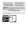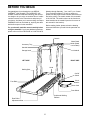
1
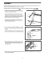
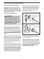
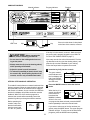
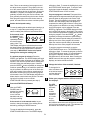
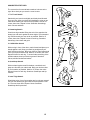
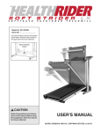
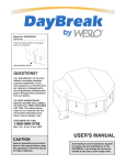
®
Model No. 831.297100
Serial No.
Serial
Number
Decal
CAUTION
Read all precautions and instructions in this manual before using
this equipment. Save this manual
for future reference.
USER'S MANUAL
SEARS, ROEBUCK AND CO., HOFFMAN ESTATES, IL 60179
®
TABLE OF CONTENTS
IMPORTANT PRECAUTIONS . . . . . . . . . . . . . . . . . . . . . . . . . . . . . . . . . . . . . . . . . . . . . . . . . . . . . . . . . . . . . . . . .3
BEFORE YOU BEGIN . . . . . . . . . . . . . . . . . . . . . . . . . . . . . . . . . . . . . . . . . . . . . . . . . . . . . . . . . . . . . . . . . . . . . . .5
ASSEMBLY . . . . . . . . . . . . . . . . . . . . . . . . . . . . . . . . . . . . . . . . . . . . . . . . . . . . . . . . . . . . . . . . . . . . . . . . . . . . . . .6
OPERATION AND ADJUSTMENT . . . . . . . . . . . . . . . . . . . . . . . . . . . . . . . . . . . . . . . . . . . . . . . . . . . . . . . . . . . . .7
HOW TO FOLD AND MOVE THE TREADMILL . . . . . . . . . . . . . . . . . . . . . . . . . . . . . . . . . . . . . . . . . . . . . . . . . .10
MAINTENANCE AND TROUBLE-SHOOTING . . . . . . . . . . . . . . . . . . . . . . . . . . . . . . . . . . . . . . . . . . . . . . . . . . .12
CONDITIONING GUIDELINES . . . . . . . . . . . . . . . . . . . . . . . . . . . . . . . . . . . . . . . . . . . . . . . . . . . . . . . . . . . . . . .14
ORDERING REPLACEMENT PARTS . . . . . . . . . . . . . . . . . . . . . . . . . . . . . . . . . . . . . . . . . . . . . . . . . .Back Cover
FULL 90 DAY WARRANTY . . . . . . . . . . . . . . . . . . . . . . . . . . . . . . . . . . . . . . . . . . . . . . . . . . . . . . . . . . .Back Cover
Note: An EXPLODED DRAWING and PART LIST are attached to the center of this manual. Please save them for
future reference.
2
IMPORTANT PRECAUTIONS
WARNING:
To reduce the risk of burns, fire, electric shock, or injury to persons, read the
following important precautions and information before operating the treadmill.
1. It is the responsibility of the owner to ensure
that all users of this treadmill are adequately
informed of all warnings and precautions.
surge suppressor (TVSS). The surge suppressor must have a UL suppressed voltage rating
of 400 volts or less and a minimum surge dissipation of 450 joules. The surge suppressor
must be electrically rated for 120 volts AC and
15 amps.
2. Use the treadmill only as described in this
manual.
3. Place the treadmill on a level surface, with at
least eight feet of clearance behind it. Do not
place the treadmill on any surface that blocks
air openings. To protect the floor or carpet
from damage, place a mat under the treadmill.
12. Keep the power cord and the surge suppressor away from heated surfaces.
4. Keep the treadmill indoors, away from moisture and dust. Do not put the treadmill in a
garage or covered patio, or near water.
13. Never move the walking belt while the power
is turned off. Do not operate the treadmill if
the power cord or plug is damaged, or if the
treadmill is not working properly. (See
BEFORE YOU BEGIN on page 5 if the treadmill is not working properly.)
5. Do not operate the treadmill where aerosol
products are used or where oxygen is being
administered.
14. Never start the treadmill while you are standing on the walking belt. Always hold the
handrails while using the treadmill.
6. Keep children under the age of 12 and pets
away from the treadmill at all times.
15. The treadmill is capable of high speeds.
Adjust the speed in small increments to avoid
sudden jumps in speed.
7. The treadmill should not be used by persons
weighing more than 250 pounds.
16. To reduce the possibility of the treadmill
overheating, do not operate the treadmill
continuously for longer than 1 hour.
8. Never allow more than one person on the
treadmill at a time.
17. Never leave the treadmill unattended while it
is running. Always remove the key and move
the on/off switch to the “off” position when
the treadmill is not in use. (See the drawing on
page 5 for the location of the on/off switch.)
9. Wear appropriate exercise clothing when
using the treadmill. Do not wear loose clothing that could become caught in the treadmill.
Athletic support clothes are recommended for
both men and women. Always wear athletic
shoes. Never use the treadmill with bare feet,
wearing only stockings, or in sandals.
18. Do not attempt to raise, lower, or move the
treadmill until it is properly assembled. (See
ASSEMBLY on page 6, and HOW TO MOVE
THE TREADMILL on page 11.) You must be
able to safely lift 45 pounds (20 kg) in order to
raise, lower, or move the treadmill.
10. When connecting the power cord (see page 7),
plug the power cord into a surge suppressor
(not included) and plug the surge suppressor
into a grounded circuit capable of carrying 15
or more amps. No other appliance should be
on the same circuit. Do not use an extension
cord.
19. When folding or moving the treadmill, make
sure that the storage latch is fully closed.
20. Inspect and tighten all parts of the treadmill
regularly.
11. Use only a single-outlet surge suppressor
that is UL 1449 listed as a transient voltage
3
21. Never insert any object into any opening.
tive. Servicing other than the procedures in
this manual should be performed by an authorized service representative only.
22. Always unplug the power cord before performing the maintenance and adjustment
procedures described in this manual. Never
remove the motor hood unless instructed to
do so by an authorized service representa-
23. This treadmill is intended for in-home use
only. Do not use this treadmill in any commercial, rental, or institutional setting.
WARNING:
Before beginning this or any exercise program, consult your physician. This
is especially important for persons over the age of 35 or persons with pre-existing health problems.
Read all instructions before using. SEARS assumes no responsibility for personal injury or property
damage sustained by or through the use of this product.
SAVE THESE INSTRUCTIONS
The decal shown below has been placed on your treadmill. If the decal is missing, or if it is not legible,
please call our toll-free HELPLINE to order a free replacement decal (see the back cover of this manual).
Apply the decal in the location shown.
4
BEFORE YOU BEGIN
Congratulations for purchasing the new WESLO
CADENCE® LX45 treadmill. The CADENCE LX45
treadmill combines advanced technology with innovative design to let you enjoy an excellent form of cardiovascular exercise in the convenience and privacy of
your home. And when you’re not exercising, the unique
CADENCE LX45 can be folded up, requiring less than
half the floor space of other treadmills.
Monday through Saturday, 7 a.m. until 7 p.m. Central
Time (excluding holidays). To help us assist you,
please note the product model number and serial number before calling. The model number of the treadmill
is 831.297100. The serial number can be found on a
decal attached to the treadmill (see the front cover of
this manual for the location).
Before reading further, please review the drawing
below and familiarize yourself with the parts that are
labeled.
For your benefit, read this manual carefully before
using the treadmill. If you have additional questions,
please call our toll-free HELPLINE at 1-800-736-6879,
Console
Water Bottle
Holder (Bottle
not included)
Accessory Tray
Handrail
Storage Latch
Key/Clip
Handrail
LEFT SIDE
RIGHT SIDE
Hood
Walking Belt
On/Off
Switch
Circuit
Breaker
Foot Rails
Power Cord
Front Wheel
Cushioned Walking
Platform
Rear Roller
Adjustment Bolts
5
ASSEMBLY
Assembly requires two people. Set the treadmill in a cleared area and remove all packing materials. Do not
dispose of the packing materials until assembly is completed.
Assembly requires the included allen wrench
and your own phillips screwdriver
1. With the help of a second person, carefully lay the
treadmill on its right side as shown (refer to the drawing
on page 5 to identify the right side).
34
1
Remove the two Extension Leg Screws (34) from the
treadmill. Insert the Extension Legs (41) into the treadmill. Make sure that the Extension Legs are turned so the
Base Pads (36) are on the indicated side. Attach each
Extension Leg with an Extension Leg Screw.
.
41
36
With the help of a second person, carefully raise the
treadmill to the upright position so the Extension Legs
(41) are resting flat on the floor.
41
34
36
2. Refer to HOW TO LOWER THE TREADMILL FOR USE
on page 11. Follow the instructions in step 2 to lower the
treadmill.
2
Attach the Storage Latch (12) to the left Upright (14) with
two Screws (30). Be careful not to overtighten the Screws.
14
30
12
3. Remove the backing from the Adhesive Clip (74). Press
the Adhesive Clip onto the base of the Uprights (14) in
the indicated location. Press the Allen Wrench (73) into
the Adhesive Clip.
3
14
73
74
4. Make sure that all parts are tightened before you use the treadmill. To protect the floor or carpet, place
a mat under the treadmill.
6
OPERATION AND ADJUSTMENT
THE PERFORMANT LUBETM WALKING BELT
This product is for use on a nominal 120-volt circuit,
and has a grounding plug that looks like the plug illustrated in drawing 1 below. A temporary adapter that
looks like the adapter illustrated in drawing 2 may be
used to connect the surge suppressor to a 2-pole
receptacle as shown in drawing 2 if a properly
grounded outlet is not available.
Your treadmill features a walking belt coated with
PERFORMANT LUBETM, a high-performance lubricant.
IMPORTANT: Never apply silicone spray or other
substances to the walking belt or the walking platform. Such substances will deteriorate the walking
belt and cause excessive wear.
1
HOW TO PLUG IN THE POWER CORD
Grounded Outlet Box
Surge Suppressor
DANGER: Improper connection
Grounding Pin
of the equipment-grounding conductor can
result in an increased risk of electric shock.
Check with a qualified electrician or serviceman if you are in doubt as to whether the
product is properly grounded. Do not modify
the plug provided with the product—if it will
not fit the outlet, have a proper outlet
installed by a qualified electrician.
Grounding Pin
Grounded Outlet
Grounding Plug
2
Grounded Outlet Box
Adapter
Your treadmill, like any other type of sophisticated
electronic equipment, can be seriously damaged by
sudden voltage changes in your home’s power.
Voltage surges, spikes, and noise interference can
result from weather conditions or from other appliances
being turned on or off. To decrease the possibility of
your treadmill being damaged, always use a surge
suppressor with your treadmill (see drawing 1 at
the right).
Surge Suppressor
Lug
Metal Screw
Surge suppressors are sold at most hardware stores
and department stores. Use only a single-outlet surge
suppressor that is UL 1449 listed as a transient voltage
surge suppressor (TVSS). The surge suppressor must
have a UL suppressed voltage rating of 400 volts or
less and a minimum surge dissipation of 450 joules.
The surge suppressor must be electrically rated for
120 volts AC and 15 amps.
The temporary adapter should be used only until a
properly grounded outlet (drawing 1) can be installed
by a qualified electrician.
The green-colored rigid ear, lug, or the like extending
from the adapter must be connected to a permanent
ground such as a properly grounded outlet box cover.
Whenever the adapter is used it must be held in place
by a metal screw. Some 2-pole receptacle outlet box
covers are not grounded. Contact a qualified electrician to determine if the outlet box cover is
grounded before using an adapter.
This product must be grounded. If it should malfunction or break down, grounding provides a path of least
resistance for electric current to reduce the risk of electric shock. This product is equipped with a cord having
an equipment-grounding conductor and a grounding
plug. Plug the power cord into a surge suppressor,
and plug the surge suppressor into an appropriate
outlet that is properly installed and grounded in
accordance with all local codes and ordinances.
7
CONSOLE DIAGRAM
Program Indicator
Manual Indicator
LED Track
Clip
Key
CAUTION:
• Do not stand on the walking belt when turning on the power.
Next, step onto the foot rails of the treadmill. Find the
clip attached to the key (see the drawing above), and
slide the clip onto the waistband of your clothing.
Follow the steps below to operate the console.
• Always wear the clip (see the drawing above)
while operating the treadmill.
• Adjust the speed in small increments.
1
• To reduce the possibility of electric shock, keep
the console dry. Avoid spilling liquids on the
console, and use only a sealed water bottle.
Insert the key fully into the console.
The green manual
mode indicator and
the four displays will
light. One indicator
will begin to flash in
the LED track.
STEP-BY-STEP CONSOLE OPERATION
The treadmill console features a manual mode and four
workout programs. When the manual mode is selected,
the speed and incline of the treadmill can be changed
with a touch of a button. As you exercise, the LED track
and the four displays will provide continuous exercise
feedback. When one of the workout programs is
selected, the console will automatically control the
speed as it guides you through an effective workout.
“On”
Position
If there is a thin sheet of clear plastic
on the face of the console, remove it.
If the key is in the console, remove it. Make sure that
the power cord is properly plugged in (see HOW TO
PLUG IN THE POWER CORD on page 7).
Before operating the
console, read the following precautions.
Before operating the
console, make sure
that the on/off switch
near the power cord
is in the “on” position.
Displays
2
Press the MODE button to select the desired
mode.
When the key is inserted, the manual
mode will be selected and the
MANUAL indicator
will be lit. If a workout program has been selected, press the MODE
button repeatedly to select the manual mode.
OFF
If you want to select one of the four workout programs, press the MODE button. The upper program
indicator will light. To select one of the other three
programs, press the MODE button repeatedly.
ON
8
Note: There are two twenty-minute programs and
two thirty-minute programs. The graphs in the center of the console show how the speed of the walking belt will change during the programs. During the
AEROBIC 1 program, for example, the speed will
gradually increase during the first ten minutes, and
then gradually decrease during the last ten minutes.
Each program begins with a two-minute warm-up
period, and ends with a two-minute cool-down period.
3
will begin to flash. To restart the walking belt, press
the START/PAUSE button again. To stop the walking belt and reset the displays, hold down the
START/PAUSE button for two seconds.
If a preset program is selected: The speed of the
walking belt will change automatically during the program as shown by the graphs in the center of the
console. The time remaining in the program will be
shown in the TIME display. When the program is
completed, the walking belt will slow to a stop. Note:
If the program is too difficult or too easy, the difficulty
level of the program can be adjusted. Press the
SPEED ▲ or ▼ button. The SPEED display will flash
and a number will appear in the display. This number
is the maximum speed that the walking belt will reach
during the program. Press the SPEED ▲ or ▼ button
repeatedly to change the maximum speed setting.
When the maximum speed setting is increased, the
difficulty level of the entire program will increase.
When the maximum speed setting is decreased, the
difficulty level of the entire program will decrease.
Set the desired speed setting.
To start the walking belt at default speed settings, go
to step 4. To adjust the speed setting before you
start the walking belt, follow the instructions below.
If the manual mode
is selected: Press
the SPEED ▲ button
repeatedly to select
the desired speed
setting. Note: The
TIME display will flash to indicate that the console
has been paused. The walking belt will not begin to
move until the START/PAUSE button is pressed
(see step 4). IMPORTANT: Select a low speed
setting when starting the walking belt.
To stop the program momentarily, press the
START/PAUSE button once. The SPEED display
will begin to flash. To restart the program, press the
START/PAUSE button again. To stop the program
and reset the displays, hold down the START/
PAUSE button for two seconds. Note: Pressing the
MODE button will also stop the program, reset the
displays, and select a different mode.
If a workout program is selected: Press the
SPEED ▲ or ▼ button. The SPEED display will begin
to flash and a number will appear in the display. This
number is the maximum speed that the walking belt
will reach during the selected program. If desired,
press the SPEED ▲ button repeatedly to change the
maximum speed setting. If the maximum speed setting is increased, the difficulty level of the entire program will increase. If the maximum speed setting is
decreased, the difficulty level of the entire program
will decrease. Note: The TIME display will flash to indicate that the console has been paused. The walking belt will not begin to move until the
START/PAUSE button is pressed (see step 4).
4
5
Change the incline of the treadmill, if desired.
To change the incline, hold down one
of the incline buttons
until the desired incline is reached.
6
Press the START/PAUSE button.
Follow your progress with the LED track and the
four displays.
The LED
Track—The
LED track
on the
console
represents
a distance
of 1/4 mile.
As you
exercise,
the indicators around the track will light one at a time
until you have completed 1/4 mile. The indicators will
then darken and another lap will begin.
After the START/
PAUSE button is
pressed, the walking
belt will begin to
move. Hold the
handrails and carefully begin walking.
If the console is in the manual mode: As you
exercise, change the speed of the walking belt as
desired by pressing the SPEED buttons.
To stop the walking belt momentarily, press the
START/PAUSE button once. The SPEED display
9
• DISTANCE/LAPS
display—This display shows the
total distance that
you have walked
and the number of
laps you have completed (one lap equals 1/4
mile). The display will alternate between one number and the other every seven seconds. An “L” will
appear in the display when the number of laps is
shown.
• TIME display—
When the manual
mode is selected,
the elapsed time
will be shown.
When one of the
preset programs is selected, the time remaining in
the program will be displayed.
hour) or an “M” for “Metric” (kilometers per hour)
will appear in the DISTANCE/LAPS display. Press
the MODE button twice to change the unit of measurement. Remove and then reinsert the key.
• CALS./FAT CALS.
display—This display shows the approximate numbers of calories
and fat calories
you have burned (see FAT BURNING on page 14
for an explanation of fat calories). Every seven
seconds, the display will change from one number
to the other. An “F” will appear in the display when
the number of fat calories is shown.
7
When you are finished, remove the key.
Step onto the foot
rails and remove the
key from the console. Store the key
in a secure place. In
addition, move the
on/off switch to the
“off” position. (See the drawing near the bottom of
page 8.)
• SPEED display—
This display shows
the speed of the
walking belt, in
miles per hour or
kilometers per
hour. An MPH or a KPH will appear in the display
to show which unit of measurement is selected.
To change the unit of measurement, hold down
the START/PAUSE button while inserting the key
into the console. An “E” for “English” (miles per
HOW TO FOLD AND MOVE THE TREADMILL
HOW TO FOLD THE TREADMILL FOR STORAGE
Unplug the power cord. Caution: You must be able to
safely lift 45 pounds (20 kg) in order to raise, lower, or
move the treadmill.
1. Hold the treadmill with your hands in the locations shown
at the right. Caution: To decrease the possibility of injury, bend your legs and keep your back straight. As
you raise the treadmill, make sure to lift with your legs
rather than your back. Raise the treadmill about halfway
to the vertical position.
10
2. Move your right hand to the position shown and hold the
treadmill firmly. Raise the treadmill until the storage latch
closes over the catch. Make sure that the storage latch
is fully engaged over the catch.
To protect the floor or carpet from damage, place a
mat under the treadmill. Keep the treadmill out of direct sunlight. Do not leave the treadmill in the storage
position in temperatures above 85° Fahrenheit.
Storage
Latch
Closed
Catch
HOW TO MOVE THE TREADMILL
Before moving the treadmill, convert the treadmill to the storage position as described above. Make sure that the storage latch is closed fully over the catch.
1. Hold the handrails and place one foot on the base as
shown.
2. Tilt the treadmill back until it rolls freely on the front wheels.
Carefully move the treadmill to the desired location. Never
move the treadmill without tipping it back, or the base
pads may come off. To reduce the risk of injury, use
extreme caution while moving the treadmill. Do not attempt to move the treadmill over an uneven surface.
Base
3. Place one foot on the base, and carefully lower the treadmill until it is resting in the storage position.
Front Wheels
HOW TO LOWER THE TREADMILL FOR USE
1. Hold the upper end of the treadmill with your right hand as
shown. Using your left thumb, press the storage latch and
hold it. Pivot the treadmill until the frame and foot rail are
past the storage latch.
Opened
Storage
Latch
2. Hold the treadmill firmly with both hands, and lower the
treadmill to the floor. Caution: To decrease the possibility of injury, bend your legs and keep your back
straight.
11
MAINTENANCE AND TROUBLE-SHOOTING
Most treadmill problems can be solved by following the simple steps below. If further assistance is
needed, call our toll-free HELPLINE at 1-800-736-6879, Monday through Saturday, 7 a.m. until 7 p.m.
Central Time (excluding holidays).
PROBLEM: The power does not turn on
SOLUTION: a. Make sure that the power cord is plugged into a surge suppressor, and that the surge suppressor
is plugged into a properly grounded outlet (see page 7). Use only a single-outlet surge suppressor
that is UL 1449 listed as a transient voltage surge suppressor (TVSS). The surge suppressor
must have a UL suppressed voltage rating of 400 volts or less and a minimum surge dissipation
of 450 joules. The surge suppressor must be electrically rated for 120 volts AC and 15 amps.
b. After the power cord has been plugged in, make sure that the key is fully inserted into the console. (See step 1 on page 8.)
c. Check the circuit breaker located on the treadmill
near the power cord. If the switch protrudes as
shown, the circuit breaker has tripped. To reset the
circuit breaker, wait for five minutes and then press
the switch back in.
c
Tripped
Reset
Tripped
Reset
d
d. Check the on/off switch located at the front of the
treadmill near the power cord. The switch must be
in the “on” position.
“On”
Position
OFF
ON
PROBLEM: The power turns off during use
SOLUTION: a. Check the circuit breaker located on the treadmill frame near the power cord (see 1. c. above). If
the circuit breaker has tripped, wait for five minutes and then press the switch back in.
b. Make sure that the power cord is plugged in.
c. Remove the key from the console. Reinsert the key fully into the console. (See step 1 on page 8.)
d. Make sure that the on/off switch is in the “on” position. (See 1. d. above.)
d. If the treadmill still will not run, please call our toll-free HELPLINE.
PROBLEM: The displays of the console do not function properly
SOLUTION: a. Remove the six screws from the hood. Carefully remove the hood. Locate the Reed Switch (86) and the
Magnet (87) on the left side of the Pulley (85). Turn
the Pulley until the Magnet is aligned with the Reed
Switch. Make sure that the gap between the
Magnet and the Reed Switch is about 1/8”. If necessary, loosen the Screw (35) and move the Reed
Switch slightly. Retighten the Screw. Re-attach the
hood, and run the treadmill for a few minutes to check
for a correct speed reading.
12
1/8”
86
85
87
35
Top
View
PROBLEM: The walking belt slows when walked on
SOLUTION: a. Use only a single-outlet surge suppressor that is UL 1449 listed as a transient voltage surge suppressor (TVSS). The surge suppressor must have a UL suppressed voltage rating of 400 volts or
less and a minimum surge dissipation of 450 joules. The surge suppressor must be electrically
rated for 120 volts AC and 15 amps.
b. If the walking belt is overtightened, treadmill performance may decrease and the walking belt may be
permanently damaged. Remove the key and UNPLUG THE POWER CORD. Using the allen wrench,
turn both rear roller adjustment bolts counterclockwise, 1/4 of a turn. When the walking belt is properly
tightened, you should be able to lift each side of the
walking belt 3 to 4 inches off the walking platform. Be
careful to keep the walking belt centered. Plug in the
power cord, insert the key and run the treadmill for a
few minutes. Repeat until the walking belt is properly
tightened.
b
3”–4”
Rear Roller Adjustment Bolts
c. If the walking belt still slows when walked on, please call our toll-free HELPLINE.
PROBLEM: The walking belt is off-center when walked on
SOLUTION: a. If the walking belt has shifted to the left, first remove
the key and UNPLUG THE POWER CORD. Using
the allen wrench, turn the left rear roller adjustment
bolt clockwise, and the right bolt counterclockwise,
1/4 of a turn each. Be careful not to overtighten the
walking belt. Plug in the power cord, insert the key
and run the treadmill for a few minutes. Repeat until
the walking belt is centered.
b. If the walking belt has shifted to the right, first remove
the key and UNPLUG THE POWER CORD. Using
the allen wrench, turn the left rear roller adjustment
bolt counterclockwise, and the right bolt clockwise,
1/4 of a turn each. Be careful not to overtighten the
walking belt. Plug in the power cord, insert the key
and run the treadmill for a few minutes. Repeat until
the walking belt is centered.
c. If the walking belt slips when walked on, first remove
the key and UNPLUG THE POWER CORD. Using
the allen wrench, turn both rear roller adjustment
bolts clockwise, 1/4 of a turn. When the walking belt
is correctly tightened, you should be able to lift each
side of the walking belt 3 to 4 inches off the walking
platform. Be careful to keep the walking belt centered. Plug in the power cord, insert the key and run
the treadmill for a few minutes. Repeat until the walking belt is properly tightened.
13
a
b
c
CONDITIONING GUIDELINES
prolonged periods of time. This increases the demand
on the heart to pump blood to the muscles, and on the
lungs to oxygenate the blood. For aerobic exercise,
adjust the speed and incline of the treadmill until your
heart rate is near the higher number in your training
zone.
WARNING:
Before beginning
this or any exercise program, consult your
physician. This is especially important for individuals over the age of 35 or individuals
with pre-existing health problems.
HOW TO MEASURE YOUR HEART RATE
To measure
your heart rate,
stop exercising
and place two
fingers on your
wrist as shown.
Take a sixsecond heartbeat count, and
multiply the result by 10 to find
your heart rate.
For example, if your six-second heartbeat count is 14,
your heart rate is 140 beats per minute. (A six-second
count is used because your heart rate will drop rapidly
when you stop exercising.) Adjust the intensity of your
exercise until your heart rate is at the proper level.
The following guidelines will help you to plan your exercise program. Remember—these are general guidelines only. For more detailed exercise information, obtain a reputable book or consult your physician.
EXERCISE INTENSITY
Whether your goal is to burn fat or to strengthen your
cardiovascular system, the key to achieving the desired
results is to exercise with the proper intensity. The
proper intensity level can be found by using your heart
rate as a guide. The chart below shows recommended
heart rates for fat burning and aerobic exercise.
WORKOUT GUIDELINES
Each workout should include the following three parts:
A Warm-up—Start each workout with 5 to 10 minutes
of stretching and light exercise. A proper warm-up increases your body temperature, heart rate, and circulation in preparation for more strenuous exercise.
To find the proper heart rate for you, first find your age
at the bottom of the chart (ages are rounded off to the
nearest ten years). Next, find the three numbers above
your age. The three numbers are your “training zone.”
The lower two numbers are recommended heart rates
for fat burning; the higher number is the recommended
heart rate for aerobic exercise.
Training Zone Exercise—After warming up, increase
the intensity of your exercise until your heart rate is in
your training zone for 20 to 60 minutes. (During the
first few weeks of your exercise program, do not keep
your heart rate in your training zone for longer than 20
minutes.)
Fat Burning
To burn fat effectively, you must exercise at a relatively
low intensity level for a sustained period of time. During
the first few minutes of exercise, your body uses easily
accessible carbohydrate calories for energy. Only after
the first few minutes does your body begin to use
stored fat calories for energy. If your goal is to burn fat,
adjust the speed and incline of the treadmill until your
heart rate is near one of the lower two numbers in your
training zone.
A Cool-down—Finish each workout with 5 to 10 minutes of stretching to cool down. This will increase the
flexibility of your muscles and will help to prevent postexercise problems.
Exercise Frequency
To maintain or improve your condition, complete three
workouts each week, with at least one day of rest between workouts. After a few months of regular exercise, you may complete up to five workouts each week
if desired.
Aerobic Exercise
If your goal is to strengthen your cardiovascular system, your exercise must be “aerobic.” Aerobic exercise
is activity that requires large amounts of oxygen for
14
SUGGESTED STRETCHES
The correct form for several basic stretches is shown at the
right. Move slowly as you stretch—never bounce.
1
1. Toe Touch Stretch
Stand with your knees bent slightly and slowly bend forward
from your hips. Allow your back and shoulders to relax as you
reach down toward your toes as far as possible. Hold for 15
counts, then relax. Repeat 3 times. Stretches: Hamstrings,
back of knees and back.
2
2. Hamstring Stretch
Sit with one leg extended. Bring the sole of the opposite foot
toward you and rest it against the inner thigh of your extended
leg. Reach toward your toes as far as possible. Hold for 15
counts, then relax. Repeat 3 times for each leg. Stretches:
Hamstrings, lower back and groin.
3
3. Calf/Achilles Stretch
With one leg in front of the other, reach forward and place your
hands against a wall. Keep your back leg straight and your
back foot flat on the floor. Bend your front leg, lean forward and
move your hips toward the wall. Hold for 15 counts, then relax.
Repeat 3 times for each leg. To cause further stretching of the
achilles tendons, bend your back leg as well. Stretches:
Calves, achilles tendons and ankles.
4
4. Quadriceps Stretch
With one hand against a wall for balance, reach back and
grasp one foot with your other hand. Bring your heel as close
to your buttocks as possible. Hold for 15 counts, then relax.
Repeat 3 times for each leg. Stretches: Quadriceps and hip
muscles.
5. Inner Thigh Stretch
Sit with the soles of your feet together and your knees outward.
Pull your feet toward your groin area as far as possible. Hold
for 15 counts, then relax. Repeat 3 times. Stretches:
Quadriceps and hip muscles.
15
5
PART LIST—Model No. 831.297100
Key No. Qty.
1
2
3
4
5
6
7
8
9
10
11*
12
13
14
15
16
17
18
19*
20
21
22
23
24
25
26
27
28
29
30
31
32
33
34
35
36
37
38
39
40
41
42
43
44
45
46
47
48
49
50
51
52
53
54
1
2
2
2
4
1
4
6
1
1
1
1
1
1
2
5
1
1
1
1
1
6
1
1
1
1
2
1
1
9
1
2
2
2
38
4
2
2
1
1
2
1
1
1
2
4
14
1
1
2
1
4
4
1
Description
Key/Clip
Handrail Arm
Upright Endcap
Handrail Pivot Bolt
Rear Isolator Screw
Console Base
Lower Handrail Cap
Handrail Nut
Battery Cover
Incline Motor
Console Assembly
Storage Latch
Belly Pan Connector
Upright/Base
Handrail Bolt
Handrail Washer
Motor Belt
Motor Swivel Nut
Motor/Pulley/Flywheel/Fan
Pulley/Flywheel/Fan
Motor
Motor Tension Bolt/Incline Bolt
Motor Tension Washer
Motor Tension Star Washer
Motor Swivel Bolt
Wire Harness
Ground Wire Screw
Hood
Hood Shield
Screw
Latch Decal
Handrail
Frame Pivot Bolt
Extension Leg Screw
Electronics Screw
Base Pad
Wheel Bolt
Wheel
23” Cable Tie
Controller
Extension Leg
Circuit Breaker
Power Cord Grommet
Power Cord
Upright Spacer
Isolator
Belly Pan Fastener
Choke
Motor Locknut
Belt Guide
Belly Pan
Releasable Tie
Cable Tie Clamp
Motor Belly Pan
R0198A
Key No. Qty.
55
56
57
58
59
60
61
62
63
64
65
66
67
68
69
70
71
72
73
74
75
76
77
78
79
80
81
82
83
84
85
86
87
88
89
90
91
92
93
94
95
96
#
#
#
#
#
#
#
#
4
4
1
1
1
4
1
2
9
2
2
2
1
1
1
2
2
1
1
1
1
1
4
1
1
1
1
1
1
1
1
1
1
1
1
1
4
2
2
2
1
2
1
1
1
1
1
1
1
1
Description
Handrail Washer
8” Cable Tie
On/Off Switch
Lift Board
Electronics Plate
Plastic Stand-Off
Console Wire Harness
Solid Isolator
Incline Nut
Incline Wheel Bolt
Incline Wheel
Incline Wheel Nut
Belly Pan Extension
Ground Wire
Incline Leg
Upright Pivot Washer
Rear Roller Adj. Bolt
Rear Roller Endcap
Allen Wrench
Adhesive Clip
Left Foot Rail
Rear Roller
Platform Screw
Latch Catch
Walking Platform
Walking Belt
Front Roller Adjustment Bolt
Shock
Right Foot Rail
Sensor Clip
Front Roller/Pulley
Reed Switch
Magnet
Strain Relief Clip
Incline Extension
Frame
3/4” Screw
Upright Endcap Bolt
Upright Endcap Nut
Upper Handrail Pivot Nut
Grommet
Upright Plug
14” White Wire, Male/Female
8” White Wire, 2 Female
8” Blue Wire, 2 Female
8” Blue Wire, 2 Female
4” Blue Wire, 2 Female
8” Red Wire, Male/Female
8” Green Ground Wire
User’s Manual
* Includes all parts shown in the box
# These parts are not illustrated
7
71
55
4
74
16
32
55
94
7
71
72
73
8
22
55
16
64
31
47
63
3
91
76
62
89
8
90
75
22
2
15
5
10
65
22
22
66
30
6
35
35
68
27
63
78
63
35
8
66
69
63
67
46
47
35
13
62
5
77
47
46
65
35
EXPLODED DRAWING—Model No. 831.297100
47
64
22
77
47
85
38
35
37
11*
87 86
61
77 45 63
9
R0198A
46
79
47
84
80
35
63
41
1
53
35
52
51
39
35
50
47
16
56
30
30
48
30
14
35
81
82
16
30
36
16
77
83
12
92
63
46
45
54
35
34
22 24
96
36 38
63
17
23
93
44
49
18
96
30
42
20
30
36
16
43
21
19*
92
25
16
3
41
93
8
35
58
30
34
60
26
95
30
36
30
70
35
33
59
35
8
7
8
40
57
28
29
7
32
2
55
94
55
35
4
55
15
91
35
35
The model number and serial number of your WESLO CADENCE®
LX45 treadmill are listed on a decal attached to the treadmill. See
the front cover of this manual to find the location of the decal.
Model No. 831.297100
QUESTIONS?
All replacement parts are available for immediate purchase or
special order when you visit your nearest SEARS Service Center.
To request service or to order parts by telephone, call the toll-free
numbers listed at the left.
If you find that:
• you need help assembling or
operating the WESLO
CADENCE® LX45 TREADMILL
• a part is missing
• you need to schedule repair
service
call our toll-free HELPLINE
1-800-736-6879
Monday–Saturday, 7 am–7 pm
Central Time (excluding holidays)
When requesting help or service, or ordering parts, please be
prepared to provide the following information:
• The NAME OF THE PRODUCT (WESLO CADENCE® LX45
treadmill)
• The MODEL NUMBER OF THE PRODUCT (831.297100)
• The KEY NUMBER AND DESCRIPTION OF THE PART (see
the EXPLODED DRAWING and PART LIST included in this
manual)
REPLACEMENT
PARTS
If parts become worn and need
to be replaced, call the following
toll-free number
1-800-FON-PART
(1-800-366-7278)
FULL 90 DAY WARRANTY
For 90 days from the date of purchase, if failure occurs due to defect in material or workmanship in this
SEARS TREADMILL EXERCISER, contact the nearest SEARS Service Center throughout the United
States and SEARS will repair or replace the TREADMILL EXERCISER, free of charge.
This warranty does not apply when the TREADMILL EXERCISER is used commercially or for rental purposes.
This warranty gives you specific legal rights, and you may also have other rights which vary from state
to state.
SEARS, ROEBUCK AND CO., DEPT. 817WA, HOFFMAN ESTATES, IL 60179
Part No. 144078 H00117-C R0198A
Printed in USA © 1998 Sears, Roebuck and Co.