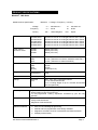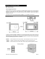
1
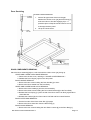
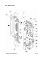
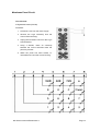
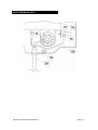
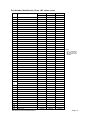
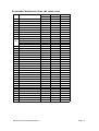
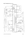
S E R V I C E
M A N U A L
For all MC-Series models manufactured from January 2001
Part No. 32Z3329e Issue No. 5
SERVICE MANUAL
MC-SERIES
CAUTION MICROWAVE EMISSIONS
DO NOT BECOME EXPOSED TO EMISSIONS FROM THE MICROWAVE
GENERATOR OR PARTS CONDUCTING MICROWAVE ENERGY
MC Series Ovens 32Z3329 Issue 4
Page 1
Table of Contents
Safety Code...........................................................................3
Product Specifications MC Series .........................................4
Installation Instructions ..........................................................5
Error Codes and Diagnostics.................................................6
A - Power Output Testing to BS EN 60335-2-25:1996 ..........7
B - Power Output Testing ......................................................8
C - Power Transformer Test ..................................................8
D - High Voltage Capacitor Test............................................9
E - High Voltage Rectifier Test ..............................................9
F - Interlock Operation.........................................................10
Exploded View MC Series ...................................................11
Door Assembly ....................................................................12
Door Replacement and Adjustment.....................................13
Door Servicing .....................................................................14
Interlock Details ...................................................................15
Membrane Panel Circuit ......................................................16
Input Wiring Details .............................................................17
Part Number Identification List ...................................... 18-19
Wiring Diagram MC-series ..................................................20
Manual Corrections and Modifications ................................21
Merrychef Limited,
Station Road West,
Ash Vale, Aldershot,
Hampshire, GU12 5XA
United Kingdom
Tel: +44 (0)1252 371000 Fax: +44 (0)1252 371007
Internet address: http://www.merrychef.co.uk
E-mail: [email protected] or [email protected]
MC Series Ovens 32Z3329 Issue 4
Page 2
SAFETY CODE
This manual is designed to assist engineers who have been on a recognised product familiarisation
and training course run by Merrychef Limited. It has been prepared to offer technical guidance for the
Merrychef MC Series Commercial Microwave Ovens.
Please remember that it is wiser not to attempt a service task if you are unsure of being able to
complete it competently, quickly, and above all safely.
To avoid injury to yourself, and to protect the appliance from possible damage, please follow this
Safety Code when servicing these ovens.
Before attempting to repair the oven, check it for microwave leakage.
Check that the oven is not emitting microwaves, even when supposedly not in operation.
Check that the oven is not operating continuously, whether the display indicates cooking or
not.
Always discharge the HT capacitors before working on the oven using a suitably insulated 10
MΩ Resistor
Before removing the rear cover from the oven, do all of the following:
• Switch off the mains supply and remove the plug from the wall socket.
or
• If the oven is hard wired, ensure that the power is turned off at the isolator switch.
Note: the oven does NOT have an On/Off switch.
Upon completion of a service on an MC Series oven, or before reconnecting the appliance to the
mains supply for testing, check all of the following points:
•
•
•
•
•
•
•
All internal electrical connections are correct.
All wiring insulation is correct and is not touching a sharp edge.
All Earth connections are electrically and mechanically secure.
All four door safety interlocks are secure and mechanically sound.
The door operation is smooth.
The door activates all four of the door interlock switches in the correct order.
All fuse-holder safety covers are correctly fitted.
Before finishing the service call, recheck the following points:
•
•
•
•
All of the electronics are functioning correctly, and all of the touch pads are working.
The power output of the oven is correct (see pages 7 & 8 ).
Microwave emission is below permissible limit - 5 mW/cm² (see BS EN 60335-2-90:1998).
Oven has correct 50 mm air gap all round. Air flow should not be restricted.
MC Series Ovens 32Z3329 Issue 4
Page 3
PRODUCT SPECIFICATIONS
Model No. MC-Seies
Model No. + Voltage + Frequency + Country
Model Number Specification:
Voltage
2 =
220-230V a.c.
4=
230-240V a.c.
Frequency
5 =
50 Hz
6=
60 Hz
Country
UK =
EX =
Export
United Kingdom
Power Requirements
MC1000C45UK
MC1000C25EX
MC1400C45UK
MC1400C25EX
MC1800C45UK
MC1800C25EX
230-240V ac 50 Hz 13.0A Single Phase 2 Wire + Earth
220-230V ac 50 Hz 14.2A Single Phase 2 Wire + Earth
230-240V ac 50 Hz 13.0A Single Phase 2 Wire + Earth
220-230V ac 50 Hz 14.2A Single Phase 2 Wire + Earth
230-240V ac 50 Hz 13.0A Single Phase 2 Wire + Earth
220-230V ac 50 Hz 14.2A Single Phase 2 Wire + Earth
Power Output
Microwave 100%
MC1000
MC1400
MC1800
1000W ( IEC 705 )
1400W ( IEC 705 )
1800W ( IEC 705 )
External Dimensions
Height
Width
Depth
335 mm ( Plus 50 mm minimum clearance above )
510 mm ( Plus 50 mm minimum clearance each side )
415 mm ( Plus 50 mm clearance behind )
Internal Dimensions
Height
Width
Depth
Capacity
210 mm
330 mm
330 mm
23 litres (0.81 ft³)
Weight
Nett
Gross packed
30 kg
35 kg
Construction
C a v i t y
Settings
Microwave
Timer
& 304 Stainless Steel
100%, 75%, 50%, progressive Defrost
Up to 9 minutes 59 seconds
Up to 3 cooking stages of up to 9 minutes 59 seconds
each (Programmed)
Control System
Wipe-clean touch pad operating microprocessor based control system.
Direct readout of time and power set.
10 Pre-programmed cooking sequences accessed by just two key
presses.
Safety Features
Four door interlock switches.
Cavity Overheat Sensor.
Magnetron Overheat Sensor.
Additional Features
•
•
•
•
Easy-to-use multistage programming.
Manual and Pre-programmed mode always available
Magnetron soft-start circuit for increased life and faster activation.
Multiple product facility.
MC Series Ovens 32Z3329 Issue 4
Page 4
INSTALLATION INSTRUCTIONS
MC Series Ovens
Power Supply Requirements
The MC–Series oven should be connected to a suitable electricity supply, which can cope with the
switching-on surge that occurs with certain types of catering equipment, such as microwaves.
Because of this requirement, we strongly recommend that a separate, suitably rated supply is
installed for the oven.
The supply for the oven should be fitted with a Type "C" circuit breaker, rated at 16A.
Positioning the Oven
In order to maintain adequate ventilation for air intake and exhaust, and to allow access for
cleaning filters, you must allow a minimum of 50 mm clearance all around the oven. Air intake
temperature should not exceed 35°C - excessive temperature can lead to reduced operating duty
cycle or premature ageing of internal components.
ALWAYS
Place containers in the cavity carefully - impact damage may chip the oven shelf
NEVER
Install an oven above fryers, grills, griddles or any other major heat source
NEVER
Stack machines on top of each other without using the stacking adapter provided.
Stacking Adapter
maximum
3 ovens
In a stack
MC Series Ovens 32Z3329 Issue 4
Page 5
Error Codes and Diagnostics
The MC–Series oven will identify some of the most common problems by flashing an error message
code in the time display window.
These are the error messages, and suggestions for repairing them.
MC Series Ovens 32Z3329 Issue 4
1
Door not fully shut.
Close door fully.
2
Possible electrical fault
Door switch inoperative.
1
No time has been set.
Set a time.
2
Invalid time has been set.
Set a valid time.
3
Invalid program has been Use call-back
set.
program.
to
check
Page 6
Procedure A - Power Output Test in accordance with
BS EN 60335-2-25:1996 Annex AA
This test is given in the BSI test standard for microwave ovens. It is reproduced below - not so that
you can follow it, but to show you why it is impractical in normal conditions. A simplified procedure,
which gives a good approximation to the BSI power output, is given in Procedure B which follows.
Note: This test can only be carried out on a COLD oven. If the oven has been operating, even for
only a few seconds, the power given will be lower than the oven rating. This test must also be
carried out at a stable voltage - the voltage in most kitchens varies considerably even within the
period of the test. If the oven has been operating, go to Procedure B.
You will need:
A thermometer capable of reading to ±0.1°C.
A cylindrical borosilicate glass container, 190 mm diameter, with a wall thickness
of 3 mm or less.
A calculator.
A set of scales capable of reading 1 kg to an accuracy of ± 1 g.
A glass or plastic stirrer.
A jug capable of holding over 1 litre of water.
Drinkable water which is at a temperature of 10°C ± 1°C.
A “Variac” or similar variable transformer capable of supplying the oven to ensure
a stable voltage.
WARNING: The Borosilicate Glass container has thin walls and is therefore fragile
- take care not to break it during use.
Method
A cylindrical container of borosilicate glass is used for the test. It has a maximum thickness of
3 mm, an external diameter of approximately 190 mm and a height of approximately 90 mm. The
mass of the container is determined.
At the start of the test, the oven and the empty container are at ambient temperature. Potable water
having an initial temperature of 10°C ± 1°C is used for the test. The temperature of the water is
measured immediately before it is poured into the container.
A quantity of 1000 g ± 5g of water is added to the container and its actual mass obtained. The
container is then immediately placed in the middle of the oven shelf which is in its lowest normal
position. The appliance is supplied at rated voltage and operated at the maximum power setting.
The time for the water temperature to attain 20°C ± 2°C is measured. The oven is then switched off
and the final water temperature is measured within 60’s.
NOTES:
1
2
The water is stirred before its temperature is measured.
Stirring and measuring devices are to have a low heat capacity.
The microwave power output is calculated from the formula:
P=
where
P
MW
MC
T0
T1
T2
t
4.187 MW (T2-T1) + 0.55 MC (T2-T0)
t
is the microwave power output, in watts;
is the mass of the water, in grams;
is the mass of the container, in grams;
is the ambient temperature, in °C;
is the initial temperature of the water, in °C;
is the final temperature of the water, in °C;
is the heating time in seconds, excluding the magnetron filament heat-up time.
MC Series Ovens 32Z3329 Issue 4
Page 7
Procedure B - Simplified Power Test
You will need:
A thermometer capable of reading to ±0.1°C.
A Polypropylene tray approximately 200 mm x 200 mm.
A measuring jug.
A calculator.
Water which is at a temperature of 10°C ± 2°C.
1
2
3
4
5
6
7
8
Measure 1 litre of cold water into the tray using the measuring jug.
Measure the water temperature, and record it as T[s].
Place the tray in the oven and close the door.
Turn the oven on.
Set the timer to 1:02.
Press the “100%” pad.
When the oven bleeps, open the door and remove the tray.
Stir the water thoroughly, and measure its temperature. Record this as T[e].
Calculation:
1 T[r] = T[s] - T[e].
2 Power = 78.5 x T[r]. Power is in Watts.
The power given by the above test should be within ±15% of the rated power.
Procedure C - Power Transformer Test
You will need:
A Digital Multi-meter (D.M.M.)
A Megger or similar resistance meter using 500V d.c.
1 Isolate the oven from the mains supply.
WARNING: High voltages and large currents are present at the secondary winding and filament
winding of the Power Transformer. It is very dangerous to work near this part when the
oven is on. NEVER make any voltage measurements at the High Voltage circuits,
including the magnetron filament.
WARNING: Even when the oven is not cooking, the Power Transformer has High Voltages present
because of the Soft Start circuit. Isolate the oven before testing.
2
3
4
Ensure that the High Voltage Capacitor is discharged before commencing work.
Remove all connections from the Power Transformer.
Using a D.M.M., check the continuity of the windings. Results should be as follows:
Mains winding (between tags)
Approximately 1.3 Ω
High Voltage winding (between tag & chassis)
Approximately 82 Ω
Filament winding (between terminals)
5
Less than 1 Ω
Using a Megger, test the insulation resistance between:
Primary winding and chassis
Pass if over 10 MΩ
Filament winding and chassis
Pass if over 10 MΩ
One end of the High Voltage winding is connected to the chassis, so this is not tested.
MC Series Ovens 32Z3329 Issue 4
Page 8
Procedure D - High Voltage Capacitor Test
You will need:
A Digital Multi-meter (D.M.M.)
A Megger or similar resistance meter using 500V d.c.
1 Isolate the oven from the mains supply.
2 Ensure that the High Voltage Capacitor is discharged before commencing work.
WARNING: High voltages and large currents are present at the High Voltage Capacitor. It is very
dangerous to work near this part when the oven is on. NEVER make any voltage
measurements at the High Voltage circuits, including the magnetron filament .
WARNING: Even when the oven is not cooking, the High Voltage Capacitor has High Voltages
present because of the Soft Start circuit. Isolate the oven before testing.
3 Remove all connections from the High Voltage Capacitor.
4 Using a D.M.M., check for continuity between the terminals & compare results with table.
5 Using a Megger, test the insulation resistance between the terminals and the case.
Between Terminals
Between Terminals and Case
Pass if approximately 10 MΩ
Pass if open circuit
Procedure E - High Voltage Rectifier Test
You will need:
A Megger or similar resistance meter using 500V d.c.
WARNING: High voltages and large currents are present at the High Voltage Rectifier. It is very
dangerous to work near this part when the oven is on. NEVER make any voltage
measurements at the High Voltage circuits, including the magnetron filament .
WARNING: Even when the oven is not cooking, the High Voltage Rectifier has High Voltages
present because of the Soft Start circuit. Isolate the oven before testing.
1
2
3
4
Isolate the oven from the mains supply.
Ensure that the High Voltage Capacitor is discharged before commencing work.
Remove all connections from the High Voltage Rectifier.
Using the Megger, test for continuity in both directions. Compare results with following table.
Open Circuit both ways
FAIL
Conducts one way only
PASS
Short Circuit both ways
FAIL
Conducts one way, leaks the other
FAIL
MC Series Ovens 32Z3329 Issue 4
Page 9
DOOR INTERLOCK OPERATION
Door Interlock Operation
The door on the oven is monitored by four microswitches. Three of these are used in the
conventional “Primary, Secondary and Monitor” switch arrangement shown below, while the fourth is
a low-voltage switch linked directly to the control circuitry.
MC– Series
Door Interlock Arrangement
66d
L
66a
Power In
66c
6 6
Power Out
N
The switches operate as follows:
1.
Monitor Switch [66b , Top ]. As the door is closed, the monitor switch is opened.
2.
Primary Interlock Switch [ 66a , Lower Middle ]. The Primary switch is then closed.
3.
Secondary Interlock Switch [ 66c , Upper Middle ]. The Secondary Switch then closes.
4.
Low voltage Switch [ 66d , Bottom ]. The Low voltage switch operates concurrently with the
Primary and Secondary switches.
When the door is opened, the switches operate in the reverse order.
MC Series Ovens 32Z3329 Issue 4
Page 10
Exploded View – MC Series
Note: Model MC1000 has only one Magnetron assembly parts 51, 61
MC Series Ovens 32Z3329 Issue 4
Page 11
Door Assembly
MC Series Ovens 32Z3329 Issue 4
Page 12
Door Replacement and Door Adjustment
DOOR REPLACEMENT
1.
2.
3.
Remove four screws holding the Upper and Lower Hinge Plate [14] to the oven cavity.
Remove Door Assembly [80] by pulling it forward.
On re-installing new door assembly, secure the upper and lower oven hinges with the four
mounting screws to the oven cavity. Make sure the door is parallel with the bottom line of
the oven cavity face and the catches pass through the catch holes correctly.
Note: After any service to the door, the oven should be checked for leakage.
DOOR ADJUSTMENT
When removing and/or loosening hinges during door adjustment or replacement, the following
adjustment criteria must be met. The door is adjusted to meet the following three conditions by
keeping the hinge screws slack.
1.
2.
3.
4.
Adjust door interlock block to a position where it smoothly locates with the catches through
the catch holes. Refer to Door Catch Adjustment.
Deviation of door alignment from horizontal line of cavity front is to be less than 1.0 mm.
The door is positioned so that it touches the cavity front.
Reinstall outer case and check for microwave leakage around the door with an approved
microwave leakage meter
MC Series Ovens 32Z3329 Issue 4
Page 13
Door Servicing
CHOKE COVER REMOVAL
1. Insert a flat type screw driver into the gap
between the Choke Cover [16] and Door Body [7]
as shown below to free the engaging clips. A
protective piece of tape should be used so as not
to damage the door panel.
2. Lift up the Choke Cover.
DOOR COMPONENTS REMOVAL
Place the Door Assembly [80] on a soft cloth with the Choke Cover [16] facing up.
UPPER AND LOWER OVEN HINGE REMOVAL
1. Remove the Choke Cover, referring to "CHOKE COVER REMOVAL".
2. Release the Door Hinges [14] from the door panel.
DOOR HANDLE REMOVAL
1. Remove the two screws holding the Door Handle [1] to door.
2. Remove the Door Handle from the Door Body.
UPPER AND LOWER DOOR CATCH REMOVAL
1. Remove the Inner Handle [3] from the door assembly.
2. Remove the three screws holding the Door Catch Bracket [8] to the Door Body.
3. Release the Door Spring [11] from the tab of the Door Catch Link Rod [10] and Door
Catch Bracket.
4. Release the Catches [9] from Door Catch Link Rod and Door Catch Bracket.
DOOR OUTER SKIN REMOVAL
1. Set the four tabs of the Door Outer Skin [4] upright.
2. Remove the Door Outer Skin from the Door Body [7].
DOOR GLASS REMOVAL
1. Remove the four screws holding the two Glass Locators [5] to the Door Body [7].
MC Series Ovens 32Z3329 Issue 4
Page 14
Door Interlock Details
MC Series Ovens 32Z3329 Issue 4
Page 15
Membrane Panel Circuit
You will need:
A Digital Multi-meter (D.M.M.)
Procedure:
1. Isolate the oven from the mains supply.
2. Remove the Logic Assembly from the
Control Panel Housing.
3. Unplug the membrane “tail” from the Logic
PCB Assembly.
4. Using a D.M.M., check for continuity
between the correct terminals when the
pads are pressed.
5. When the panel has been tested, reassemble and re-test the control housing.
MC Series Ovens 32Z3329 Issue 4
Page 16
INPUT WIRING DETAILS
MC Series Ovens 32Z3329 Issue 4
Page 17
Part Number Identification Chart: MC series ovens
No
Description
MC1000
MC1400
MC1800
Part No.
Part No.
Part No.
1
Outer Handle
30M0001
30M0001
30M0001
2
Handle Bearing (4)
30M0002
30M0002
30M0002
3
Inner Handle
30M0003
30M0003
30M0003
4
Door Outer Skin
30M0004
30M0004
30M0004
5
Glass Locator
30M0005
30M0005
30M0005
6
Outer Door Glass
30M0006
30M0006
30M0006
7
Door Body
30M0007
30M0007
30M0007
8
Door Catch Bracket
30M0008
30M0008
30M0008
9
Door Catch (2)
30M0009
30M0009
30M0009
10
Door Catch Link Rod
30M0010
30M0010
30M0010
11
Door Spring
30M0011
30M0011
30M0011
12
Oven Cavity MC-1000
30M0012
30M0036
30M0036
13
Door Catch Crank
30M0013
30M0013
30M0013
14
Upper / Lower Hinge Plate
30M0014
30M0014
30M0014
15
Inner Door Film
30M0015
30M0015
30M0015
16
Choke Cover
30M0016
30M0016
30M0016
17
Control Pnl Cover ( see note 1.)
30M0017
30M0017
30M0017
18
MC-Series Membrane
40M0956
40M0956
40M0956
19
Display Screen
30M0019
30M0019
30M0019
20
Control Housing Moulding
30M0020
30M0020
30M0020
21
MC Series Logic PCB Assy
11M0326
11M0326
11M0326
22
Housing Support Bracket
30M0022
30M0022
30M0022
23
MC Series Relay PCB Assy
11M0327
11M0327
11M0327
24
10 Way Ribbon Cable Assy
11E0051
11E0051
11E0051
25
Insulating Sheet
30M0025
30M0025
30M0025
26
Mains Cable Assy
31Z0220
31Z0220
31Z0220
27
Mica Plate
30M0027
30M0027
30M0027
28
Stirrer
30M0028
30M0028
30M0028
29
Decorative Trim LH
30M0029
30M0029
30M0029
30
Decorative Trim Top
30M0030
30M0030
30M0030
31
Air Inlet Filter
30M0031
30M0031
30M0031
32
Chassis
30M0032
30M0032
30M0032
HV Transformer J1342
30M0035
————
————
HV Transformer J1338
————
30M0033
30M0033
34
Decorative Trim RH
30M0034
30M0034
30M0034
35
Strain Relief Bush
31Z1036
31Z1036
31Z1036
36
Oven Cavity MC1400/1800
30M0036
30M0036
30M0036
37
Lamp Cover Film
30M0037
30M0037
30M0037
38
Lamp
30M0038
30M0038
30M0038
39
Lamp Holder
30M0039
30M0039
30M0039
40
Lamp Bracket
30M0040
30M0040
30M0040
41
Air Outlet Duct
30M0041
30M0041
30M0041
42
Temp Sensor
30M0042
30M0042
30M0042
43
Thermal Fuse
30M0043
30M0043
30M0043
44
Lamp Cover
30M0044
30M0044
30M0044
45
Back Case
30M0045
30M0045
30M0045
33
MC Series Ovens 32Z3329 Issue 4
Note 1.
Part 17 supplied as
MC 1800, remove
label for MC1000 &
MC1400
Page 18
Part Number Identification Chart: MC series ovens
No
Description
MC1000
MC1400
MC1800
Part No
Part No
Part No
46
Rear Air Guide
30M0046
30M0046
30M0046
47
Upper Air Duct
30M0047
30M0047
30M0047
48
Cooling Fan Assembly
30M0048
30M0048
30M0048
49
Gold Resistor
30Z0283
30Z0283
30Z0283
51
Magnetron Thermostat
30M0051
30M0051
30M0051
52
10A Fuse In-line Assembly
11M0330
11M0330
11M0330
56
Fan Scroll
30M0056
30M0056
30M0056
57
Main Capacitor Bracket
30M0057
30M0057
30M0057
58
Capacitor Clamp
30M0058
30M0058
30M0058
HV Capacitor 0.74uF
————
30Z0377
————
HV Capacitor 0.88uF
————
30Z0987
————
HV Capacitor 1.0uF
30M0059
————
30M0059
HV Capacitor 1.1uF
————
————
30Z0989
60
Rear Panel
30M0060
30M0060
30M0060
61
Magnetron
30M0061
30M0061
30M0061
62
Magnetron Air Splitter
30M0062
30M0062
30M0062
63
Magnetron Cooling Duct
30M0063
30M0063
30M0063
64
Cooling Duct Cover
30M0064
30M0064
30M0064
65
Interlock Holder
30M0065
30M0065
30M0065
Microswitch V5A010CB (4)
30Z0233
30Z0233
30Z0233
59
66 a-d
67
Fuse Cover
30Z1080
30Z1080
30Z1080
68
Spring 1
30M0068
30M0068
30M0068
69
Spring 2
30M0069
30M0069
30M0069
70
Top Lever
30M0070
30M0070
30M0070
71
Middle Lever
30M0071
30M0071
30M0071
72
Bottom Lever
30M0072
30M0072
30M0072
73
Filter Bracket
40M0961
40M0961
40M0961
74
16A Mains Filter
30Z0997
30Z0997
30Z0997
75
Fuse Holder
30Z0231
30Z0231
30Z0231
76
Fuse 13A Anti surge
30Z0168
30Z0168
30Z0168
77
——–
————
78
HV Diode Assy
30M0078
30M0078
30M0078
79
Self-Adhesive Foot
30M0079
30M0079
30M0079
80
Door Assembly
11M0334
11M0334
11M0334
81
Power Relay
30M0081
30M0081
30M0081
82
Oven Shelf
30M0082
30M0082
30M0082
83
HT Lead 1
30M0083
30M0083
30M0083
84
HT Lead 2
————
30M0084
30M0084
91
Mains Filter Bracket
30M0091
30M0091
30M0091
MC Series Ovens 32Z3329 Issue 4
Page 19
CIRCUIT DIAGRAM: MC Series ovens
MC Series Ovens 32Z3329 Issue 4
Page 20
Manual Corrections and Modifications
Whilst every effort has been made to ensure that the information contained in this manual is accurate
and complete, if you believe that an error has been made, or if you have any suggestions for how the
manual could be improved, please fill in and return this form. A review of any forms returned will be
made on a regular basis, and the manual will be updated if required.
Name
Address
Page on which error occurs (if appl) - MC Series:
Description of error
Suggestion for improvement to manual
Please return this form to:
Or Fax it on:
E-Mail
Quality Department
Merrychef Ltd
Station Road West
Ash Vale
Aldershot
Hampshire
GU12 5XA
+44 (0) 1252 371007
[email protected]
MC Series Ovens 32Z3329 Issue 4
Page 21