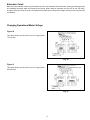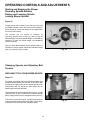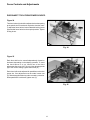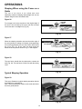
1
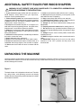
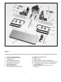
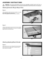
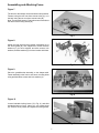
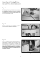
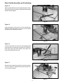
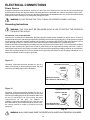
1 HP Professional
Wood Shaper
(Model 43-290C)
Part No. 1235200
Dated 8-30-01
Copyright © 2001 Delta Machinery
A Pentair Company
To learn more about DELTA MACHINERY
visit our website at: www.deltamachinery.com.
For Parts, Service, Warranty or other Assistance,
please call 1-800-GO-DELTA (463-3582)
INSTRUCTION MANUAL
Français au verso
TABLE OF CONTENTS
SAFETY INSTRUCTIONS ......................................... 3,4
UNPACKING MACHINE ............................................. 4,5
ASSEMBLY INSTRUCTIONS
Attaching Extensions Wing ................................................... 6
Attaching Adjusting Wrench and Bracket .............................. 6
Assembling and Attaching Fence ......................................... 7
Assembling and Changing Spindles ..................................... 8
Stock Guide Assembly and Positioning ................................ 9
ELECTRICAL CONNECTIONS
Power Source ..................................................................... 10
Grounding Instructions ....................................................... 10
Extension Cords ................................................................. 11
Changing Operational Motor Voltage ................................. 11
OPERATING CONTROLS
AND ADJUSTMENTS
Starting and Stopping the Shaper ...................................... 12
Reversing Spindle Rotation ................................................ 12
Raising and Lowering Spindle ............................................ 12
Locking the Shaper Spindle................................................ 12
Changing Speeds and Adjusting Belt Tension .................... 12
Fence Controls and Adjustments........................................ 13
OPERATIONS
Shaping When Using the Fence as a Guide ...................... 14
Typical Shaping Operations................................................ 14
ACCESSORIES ............................................................... 15
PARTS, SERVICE AND WARRANTY ................... 16
2
SAFETY RULES
Woodworking can be dangerous if safe and proper
operating procedures are not followed. As with all machinery,
there are certain hazards involved with the operation of
the product. Using the machine with respect and caution
will considerably lessen the possibility of personal injury.
However, if normal safety precautions are over- looked or
ignored, personal injury to the operator may result. Safety
equipment such as guards, push sticks, hold-downs,
featherboards, goggles, dust masks and hearing protection
can reduce your potential for injury. But even the best guard
won’t make up for poor judgment, careless or inattention.
Always use common sense and exercise caution in the
workshop. If a procedure feels dangerous, don’t try it.
Figure out an alternative procedure that feels safer.
REMEMBER: Your personal safety is your responsibility.
This machine was designed for certain applications only.
Delta Machinery strongly recommends that this machine
not be modified and /or used for any application other than
for which it was designed. If you have any questions relative
to a particular application, DO NOT use the machine until
you have first contacted Delta to determine if it can or
should be performed on the product.
Technical Service Manager
505 Southgate Drive
Guelph, ONTARIO N1H 6M7
WARNING: FAILURE TO FOLLOW THESE RULES MAY RESULT IN SERIOUS PERSONAL INJURY.
1. For your own safety, read instruction manual before
operating the tool. Learn the tool’s application and
limitations as well as the specific hazards peculiar to it.
2. Keep guards in place and in working order.
3. Always wear eye protection. Wear safety glasses.
Everyday eyeglasses only have impact resistant lenses;
they are not safety glasses. Also use face or dust mask if
cutting operation is dusty. These safety glasses must
conform to ANSI Z87.1 requirements. Note: Approved
glasses have Z87 printed or stamped on them.
4. Remove adjusting keys and wrenches. Form a habit
of checking to see that keys and adjusting wrenches are
removed from tool before turning it “ON”.
5. Keep work area clean. Cluttered areas and benches
invite accidents.
6. Don’t use in dangerous environment. Don’t use
power tools in damp or wet locations, or expose them to
rain. Keep work area welllighted.
7. Keep children and visitors away. All children and
visitors should be kept a safe distance from work area.
8. Make workshop childproof – with padlocks, master
switches, or by removing starter keys.
9. Don’t force tool. It will do the job better and safer at
the rate for which it was designed.
10. Use the right tool. Don’t force tool or attachment to do
a job fro which it was not designed.
11. Wear proper apparel. No loose clothing, gloves,
neckties, rings, bracelets, or other jewelry to get caught in
moving parts. Nonslip footwear is recommended. Wear
protective hair covering to contain long hair.
12. Secure work. Use clamps or a vise to hold work when
practical. It’s safer than using your hand and frees both
hands to operate tool.
13. Don’t overreach. Keep proper footing and balance at all
times.
14. Maintain tools in top condition. Keep tools sharp and
clean for best and safest performance. Follow instructions
for lubricating and changing accessories.
15. Disconnect tools before servicing and when changing
accessories such as blades, bits, cutters, etc.
16. Use recommended accessories. The use of
accessories and attachments not recommended by Delta
may cause hazards or risk of injury to persons.
17. Reduce the risk of unintentional starting. Make sure
switch is in “OFF” position before plugging in power cord.
In the event of a power failure, move switch to the “OFF”
position.
18. Never stand on tool. Serious injury could occur if the
tool is tipped or if the cutting tool is accidentally contacted.
19. Check damaged parts. Before futher use of the tool,
a guard or other part that is damaged should be carefully
checked to ensure that it will operate properly and perform
its intended function - check for alignment of moving parts,
binding of moving parts, breakage of parts, mounting, and
any other conditions that may affect its operation. A guard
or other part that is damaged should be properly repaired
or replaced.
20. Direction of feed. Feed work into a blade or cutter
against the direction of rotation of the blade or cutter only.
21. Never leave tool running unattended. Turn power
off. Don’t leave tool until it comes to a complete stop.
22. Stay alert, watch what you are doing, and use
common sense when operating a power tool. Do not
use tool while tired or under the influence of drugs,
alcohol, or medication. A moment of inattentioin while
operating power tools may result in serious personal injury.
23. Make sure tool is disconnected from power supply
while motor is being mounted, connected or reconnected.
24. The dust generated by certain woods and wood
products can be injurious to your health. Always operate
machinery in well ventilated areas and provide for proper
dust removal. Use wood dust collection systems whenever
possible.
WARNING: Some dust created by power
25.
sanding, sawing, grinding, drilling, and other
construction activities contains chemicals known to cause
cancer, birth defects or other reproductive harm. Some
examples of these chemicals are:
• Lead from lead-base paints
• Crystalline silica form bricks and cement and other masonry
products.
• Arsenic and chromium from chemically-treated lumber.
Your risk from these exposures varies, depending on how
often you do this type of work. to reduce your exposure to
these chemicals: work in a well ventilated area, and work
with approved safety equipment, such as those dust masks
that are specially designed to filter out microscopic particles.
SAVE THESE INSTRUCTIONS
Refer to them often and use them to instruct others.
3
ADDITIONAL SAFETY RULES FOR WOOD SHAPERS
WARNING: DO NOT OPERATE YOUR WOOD SHAPER UNTIL IT IS COMPLETELY ASSEMBLED AND
INSTALLED ACCORDING TO THE INSTRUCTIONS.
1. If you are not throughly familiar with the operation of
Wood Shapers, obtain advice form your supervisor,
instructor or other qualified person.
2. Follow all wiring codes and recommended electrical
connections. Make certain that the tool is properly grounded.
3. Never turn the tool “ON” before clearing the table of all
objects (tools, scraps of wood, etc.).
4. Do not process materials less than 12” in length or 4” in
width without special supporting fixtures. Use push sticks,
featherboards, or hold downs whenever possible.
5. Always use a miter gauge and a clamp attachment when
edge shaping work less than 6” wide. Remove the fence
during this operation.
6. Avoid awkward hand positions. A sudden slip could allow
the hand to contact the cutter.
7. Keep hands away from cutting tool.
8. Never run the stock between the fence and the cutter.
9. Do not feed material that is warped, contains knots, or is
embedded with foreign objects, such as nails or staples.
10. Never start the tool with the stock in contact with the
cutter.
11. Never reach under the table while the tool is running.
12. Never perform layout, assembly, or set-up work on the
table while the tools is operating.
13. Keep cutters sharp and free from rust and pitch.
14. Adjust the fence halves so that the cutter opening is
never more than is required to clear the cutter.
15. Always lock the fence hardware after making fence
adjustments.
16. Properly secure the cutters before starting the tool.
17. Do not perform any operation freehand. Always use
the fence for straight shaping and the miter gauge for edge
shaping.
18. Always keep the motor access panels closed while
operating the tool.
19. Before leaving the machine, make sure the work area is
clean.
20. IMPORTANT: When the tool is not in use, the switch
should be in the “OFF” position and the power cord
disconnected.
UNPACKING THE MACHINE
Carefully unpack the Delta Shaper and all loose items from the shipping containers. Check to see that you have all of the
items listed in this manual. Do not turn the machine ON if any of these items are missing. You may cause injury to yourself
and also damage the machine.
Figure 2
The basic shaper unit is shipped as shown here. The table
top, table inserts, and operating controls are already
installed. Remove any packing material and tape from inside
and outside of machine.
Fig. 2
4
Fig. 3
Figure 3
The following shaper parts require assembly. Please be sure all of the listed parts are included before starting assembly.
1.
2.
3.
4.
5.
6.
7.
8.
9.
Center Guard and Dust Chute
1/2” and 3/4” Spindles w/collars
Tie Rod and Nut
Fence Bracket Assembly (2)
Adjusting Wrench and Bracket
Adjustable Fence Halves (2)
Stock Guide Rods (2)
Stock Guide Brackets (4)
Stock Guide Allen Lock Screws (6)
10.
11.
12.
13.
14.
15.
Stock Guide Spring Bars (4)
Tools (3)
Extension Wing
Wing Hex Screws (3) and Lock Washers (3)
Fence Bracket Hex Screws (2) and Lock Washers (2)
Fence Adjuster Allen Screws (2), Lock Washers (2),
and Flat Washers (2)
16. Fence Assembly Allen Screws (2) and Lock
Washers(2)
5
ASSEMBLY INSTRUCTIONS
WARNING: FOR YOUR OWN SAFETY, DO NOT PLUG SHAPER IN OUTLET UNTIL THE TOOL IS
COMPLETELY ASSEMBLED AND YOU READ AND UNDERSTAND THE ENTIRE INSTRUCTION MANUAL.
Attaching Extension Wing to Shaper Table
Figure 4
Using supplied hex head screws and washers (A), attach
the extension wing (B) to shaper table.
Note: Loosely tighten screws until next step is complete.
Fig. 4
Figure 5
Using a straight edge (A),check the level of the extension
wing (B) with the shaper table (C). Once this is completed,
tighten all three hex head screws.
Fig. 5
Attaching Adjusting Wrench Bracket
Figure 6
Attach bracket (A) to rear of shaper table using supplied
allen screw and lock washer (B). The wrench (C) will
slide in and out as needed.
Fig. 6
6
Assembling and Attaching Fence
Figure 7
The fence for this shaper can be mounted in two positions.
Forward, using the two front fence mount holes (A), or in
the back using the two rear fence mount holes (B).
Note: The two table inserts (C) have been removed to show
the three insert leveling screws (D).
Fig. 7
Figure 8
Attach the right and left fence bracket assemblies (A) to
the center guard (B). Use supplied hex screws and lock
washers (C) for fence adjuster and allen screws, lock
washers, and flat washers (D) for fence bracket lockdown.
Fig. 8
Figure 9
Place the guard/bracket assembly on the shaper table.
Fasten assembly to the front or rear fence mounting holes
using provided allen screws and lock washers (A).
Fig. 9
Figure 10
Loosen indexable locking levers ( B in Fig. 9 ) and slide
extruded aluminum fence halves (C) over locking dogs
(D). Select a fence position and tighten the locking levers.
Fig. 10
7
Assembling and Changing Spindles
DISCONNECT TOOL FROM POWER SOURCE.
Figure 11
Thread the end of the tie rod with the shorter threads (A)
into the spindle bottom (B). Insert tie rod and spindle into
the spindle cartridge, making sure the notches in the spindle
(C) engage with the pins (D) on the spindle cartridge. Thread
nut (E) on the bottom end of tie rod.
Fig. 11
Figure 12
Place the special wrench on top spindle flats (A). Tighten
tie rod nut (B) with supplied open end wrench.
Fig. 12
Figure 13
There are four different collars supplied with both the 1/2”
spindle and the 3/4” spindle. These collars allow the cutter
to be positioned at various locations on the spindle. When
assembling cutters to a spindle, place the cutter as close
to the bottom as possible. This reduces the chance of
spindle run-out. With the cutter and collar selections in place,
thread the RIGHT threaded hold down nut (A) onto spindle
and tighten. Next thread the LEFT threaded locking nut (B)
onto spindle and tighten.
Fig. 13
8
Stock Guide Assembly and Positioning
Figure 14
Slide two guide brackets (A) onto a guide assembly rod (B).
Thread two allen lock screws(C) into threaded holes on guide
brackets and hand tighten.
Fig. 14
Figure 15
Insert stock guide rod (A) thru hole in fence bracket (B).
Thread an allen lock screw (C) into top of fence bracket
and tighten with adjusting hex wrench.
Fig. 15
Figure 16
Loosen the two allen lock screws (A), slide spring bars (B)
under bracket lock screws and over guide rod. Position the
guide spring bars and guide brackets, then tighten lock
screws with adjusting hex wrench.
Fig. 16
Figure 17
Assemble the remaining stock guide in the same manner.
This view shows the complete stock guide assembly setup for a typical operation.
9
Fig. 17
ELECTRICAL CONNECTIONS
Power Source
A seperate electrical circuit should be used for your tool. This circuit should not be less than #12 wire and should be
protected with a 20 amp time lag fuse. Before connecting the motor to the power line, make sure the switch is in the “OFF”
position and be sure the electric current is of the same characteristics as indicated on the tool. All line connections should
make good contact. Running on low voltage will damage the motor.
WARNING: DO NOT EXPOSE THE TOOL TO RAIN OR OPERATE IN DAMP LOCATIONS.
Grounding Instructions
WARNING: THIS TOOL MUST BE GROUNDED WHILE IN USE TO PROTECT THE OPERATOR
FROM ELECTRIC SHOCK.
All grounded, cord-connected tools:
In the event of a malfunction or breakdown, grounding provides a path of least resistance for electric shock. This tool is
equipped with an electric cord having an equipment-grounding conductor and a grounding plug. The plug must be plugged
into a matching outlet that is properly installed and grounded in accordance with all local codes and ordinances. Do not
modify the plug provided - if it will not fit the outlet, have the proper outlet installed by a qualified electrician.
Improper connection of the equipment-grounding conductor can result in risk of electric shock. The conductor with insulation
having an outer surface that is green with or without yellow stripes is the equipment-grounding conductor. If repair or
replacement of the electric cord or plug is necessary, do not connect the equipment grounding conductor to a live terminal.
Check with a qualified electrician or service personnel if the grounding instructions are not completely understood, or if in
doubt as to whether the tool is properly grounded.
Figure 18
Grounded, cord-connected tools intended for use on a
supply circuit having a nominal rating less than 150 volts
will have a grounding plug similar to illustration.
GROUNDED OUTLET BOX
CURRENT
CARRYING
PRONGS
GROUNDING BLADE IS
THE LONGEST OF THE 3 BLADES
Fig. 18
Figure 19
GROUNDED OUTLET BOX
Grounded, cord-connected tools intended for use on a
supply circuit having a nominal rating between 150-250 volts
will have a grounding plug similar to illustration. Make sure
the tool is connected to an outlet having the same
configurations as the plug. No adapter is
available or should be used with this tool. If the tool must
be reconnected for use on a different type of electric circuit,
the change should be made by qualified servicing
personnel.
CURRENT CARRYING
PRONGS
GROUNDING BLADE IS
THE LONGEST OF THE 3 BLADES
Fig. 19
WARNING: IN ALL CASES, MAKE SURE THE RECEPTACLE IN QUESTION IS PROPERLY GROUNDED.
10
Extension Cords
Make sure your extension cord is in good condition an is a 3-wire extension cord which has a 3-prong grounding type plug
and matching receptacle which will accept the tool’s plug. When using an extension cord, be sure to use one heavy
enough to carry the current of the tool. An undersized cord will cause a drop in line voltage, resulting in loss of power and
overheating.
Changing Operational Motor Voltage
Figure 20
This chart shows correct power input for single phase
110-120 VAC.
Fig. 20
Figure 21
This chart shows correct power input for single phase
220-230 VAC.
Fig. 21
11
OPERATING CONTROLS AND ADJUSTMENTS
Starting and Stopping the Shaper
Reversing Spindle Rotation
Raising and Lowering Spindle
Locking Shaper Spindle
Figure 22
To apply power to the machine, turn knob (A) to the right
for forward operation, and to the left for reverse operation.
Never attempt to reverse the rotation of the spindle while
the motor is still running.
The spindle can be raised or lowered by
unlocking spindle locking lever (C) and turning the
handwheel (B). To raise the spindle height, turn handwheel
clockwise. To lower the spindle height, turn handwheel
counter clockwise.
Once you have determined the proper spindle height, it is
important to lock the spindle. Rotate the indexable locking
lever (C) toward lock until it is tight.
Fig. 22
Changing Speeds and Adjusting Belt
Tension
DISCONNECT TOOL FROM POWER SOURCE.
Figure 23
The shaper is supplied with a two-step spindle pulley that
provides spindle speeds of 8,000 and 10,000 RPM. With
the belt on the upper pulley (A), the spindle speed will be
10,000 RPM. With the belt on the lower pulley (B), the
spindle speed will be 8,000 RPM.
To change speeds, loosen indexable locking lever (C), and
release tension on belt. Position belt on desired spindle
pulley, reapply tension to belt, and tighten locking lever (C).
To check for correct belt tension, use light finger pressure
on the belt between the spindle pulley and the motor drum.
A deflection of no more than 3/32” should be noted.
12
Fig. 23
Fence Controls and Adjustments
DISCONNECT TOOL FROM POWER SOURCE.
Figure 24
The fence halves (A) should be adjusted so that the opening
at the spindle is no more than is required to clear the cutter.
To adjust the fence halves, loosen indexable locking levers
(B) and slide fence halves to the required position. Tighten
locking levers.
Fig. 24
Figure 25
Each fence half can be moved independently, forward or
backward, depending on the shaping operation. To move
the fence halves in or out, loosen one of the fence
adjustment allen screw (A). Turn one of the adjusting knobs
(B) to the correct setting. Tighten allen screw (A).
Each fence half can be adjusted for parallelism to the miter
gauge slot. If an adjustment must be made, loosen nuts
(C) and with supplied allen key make necessary correction.
When parallelism is achieved, tighten nuts (C).
Fig. 25
13
OPERATIONS
Shaping When using the Fence as a
Guide
The use of the fence is the safest and most
satisfactory method of shaping. Most straight work can be
shaped using the fence described below.
Figure 26
For average work, where a portion of the original edge of
the work is not touched by the cutter, both the front and
rear fences are in a straight line (Fig. 26).
Fig. 26
Figure 27
When the shaping operation removes the entire edge of
the work (jointing or making a full bead), the shaped edge
will not be supported by the rear fence when both fences
are in line (Fig. 27). In this case, the work should be
advanced to the position shown in Fig. 27 and stopped.
Fig. 27
Figure 28
The rear fence should then be advanced to contact the
work (Fig. 28). The rear fence will be in line with the cutting
circle.
Fig. 28
Typical Shaping Operation
Figure 29
This set-up illustrates a typical shaping operation with the
fence halves in a straight line.
Note: The fence placement relative to the cutter and notice
the stock guide position.
Fig. 29
14
ACCESSORIES
A complete line of accessories is available form your Delta Supplier, Porter-Cable • Delta Factory Service Centers, and
Delta Authorized Service Stations. Please visit our Web Site www.deltamachinery.com for a catalog or for the
name of your nearest supplier.
WARNING: Since accessories other than those offered by Delta have not been tested with this product, use of
such accessories could be hazardous. For safest operation, only Delta recommended accessories should be used
with this product.
15
PARTS, SERVICE, AND WARRANTY ASSISTANCE
All Delta Machines and accessories are manufactured to high quality standards and are serviced by a network of PorterCable • Delta Factory Service Centers and Delta Authorized Service Stations. To obtain additional information regarding your
Delta quality product or to obtain accessories, parts, service, warranty assistance, or the location of the nearest service
outlet, please call 1-800-463-3582.
Two Year Limited Warranty
Delta will repair or replace, at its expense and at its option, any Delta machine,
machine part, or machine accessory which in normal use has proven to be defective
in workmanship or material, provided that the customer returns the product prepaid
to a Delta factory service center or authorized service station with proof of purchase
of the product within two years and provides Delta with reasonable opportunity to
verify the alleged defect by inspection. Delta may require that electric motors be
returned prepaid to a motor manufacturer’s authorized station for inspection and
repair or replacement. Delta will not be responsible for any asserted defect which
has resulted from normal wear, misuse, abuse or repair or alteration made or
specifically authorized by anyone other than an authorized Delta Service facility or
representative. Under no circumstances will Delta be liable for incidental or
consequential damages resulting from defective products. This warranty is Delta’s
sole warranty and sets forth the customer’s exclusive remedy, with respect to
defective products; all other warranties, express or implied, whether of
merchantability, fitness for purpose, or otherwise, are expressly disclaimed by Delta.