1
2005
YP250R
SERVICE MANUAL
1C0-F8197-E0
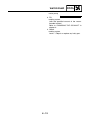
EAS00000
YP250R 2005
SERVICE MANUAL
©2007 by Yamaha Motor España, S.A.
First edition, February 2007
All rights reserved.
Any reproduction or unauthorized use
without the written permission of
Yamaha Motor España, S.A.
is expressly prohibited.
EAS00002
NOTICE
This manual was produced by the Yamaha Motor España S.A. primarily for use by Yamaha dealers
and their qualified mechanics. It is not possible to include all the knowledge of a mechanic in one
manual. Therefore, anyone who uses this book to perform maintenance and repairs on Yamaha
vehicles should have a basic understanding of mechanics and the techniques to repair these types
of vehicles. Repair and maintenance work attempted by anyone without this knowledge is likely to
render the vehicle unsafe and unfit for use.
Yamaha Motor España S.A. is continually striving to improve all of its models. Modifications and significant changes in specifications or procedures will be forwarded to all authorized Yamaha dealers
and will appear in future editions of this manual where applicable.
NOTE:
Designs and specifications are subject to change without notice.
_
EAS00005
IMPORTANT MANUAL INFORMATION
Particularly important information is distinguished in this manual by the following.
The Safety Alert Symbol means ATTENTION! BECOME ALERT! YOUR
SAFETY IS INVOLVED!
WARNING
CAUTION:
NOTE:
Failure to follow WARNING instructions could result in severe injury or death to
the vehicle operator, a bystander or a person checking or repairing the vehicle.
A CAUTION indicates special precautions that must be taken to avoid damage
to the vehicle.
A NOTE provides key information to make procedures easier or clearer.
EAS00007
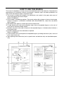
HOW TO USE THIS MANUAL
This manual is intended as a handy, easy-to-read reference book for the mechanic. Comprehensive
explanations of all installation, removal, disassembly, assembly, repair and check procedures are
laid out with the individual steps in sequential order.
1 The manual is divided into chapters. An abbreviation and symbol in the upper right corner of
each page indicate the current chapter.
Refer to “SYMBOLS”.
2 Each chapter is divided into sections. The current section title is shown at the top of each page,
except in Chapter 3 (“PERIODIC CHECKS AND ADJUSTMENTS”), where the sub-section
title(s) appears.
3 Sub-section titles appear in smaller print than the section title.
4 To help identify parts and clarify procedure steps, there are exploded diagrams at the start of
each removal and disassembly section.
5 Numbers are given in the order of the jobs in the exploded diagram. A circled number indicates a
disassembly step.
6 Symbols indicate parts to be lubricated or replaced.
Refer to “SYMBOLS”.
7 A job instruction chart accompanies the exploded diagram, providing the order of jobs, names of
parts, notes in jobs, etc.
8 Jobs requiring more information (such as special tools and technical data) are described sequentially.
1
EAS00008
2
GEN
INFO
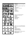
SYMBOLS
The following symbols are not relevant to
every vehicle.
Symbols 1 to 9 indicate the subject of each
chapter.
SPEC
3
4
CHK
ADJ
1 General information
2 Specifications
3 Periodic checks and adjustments
4 Chassis
5 Engine
6 Cooling system
7 Carburetor
8 Electrical system
9 Troubleshooting
CHAS
5
6
ENG
COOL
7
8
–
ELEC
CARB
9
Symbols 0 to G indicate the following.
0
0 Serviceable with engine mounted
A Filling fluid
B Lubricant
C Special tool
D Tightening torque
E Wear limit, clearance
F Engine speed
G Electrical data
TRBL
SHTG
A
B
C
D
+
T.
R.
E
F
G
H
I
J
G
E
K
M
L
B
M
M
LS
N
Symbols H to M in the exploded diagrams
indicate the types of lubricants and lubrication
points.
Symbols N to O in the exploded diagrams
indicate the following.
O
LT
H Engine oil
I Gear oil
J Molybdenum-disulfide oil
K Wheel-bearing grease
L Lithium-soap- based grease
M Molybdenum-disulfide grease
New
N Apply locking agent (LOCTITE®)
O Replace the part
EAS00010
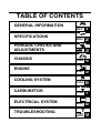
TABLE OF CONTENTS
GENERAL INFORMATION
SPECIFICATIONS
PERIODIC CHECKS AND
ADJUSTMENTS
CHASSIS
ENGINE
COOLING SYSTEM
CARBURETOR
GEN
INFO
1
SPEC
2
CHK
ADJ
3
CHAS
4
ENG
5
COOL
6
CARB
7
–
ELECTRICAL SYSTEM
TROUBLESHOOTING
+
ELEC
8
TRBL
SHTG
9
GEN
INFO
CHAPTER 1
GENERAL INFORMATION
IDENTIFICATION ............................................................................................ 1-1
VEHICLE IDENTIFICATION NUMBER .....................................................1-1
MODEL LABEL.......................................................................................... 1-1
MULTI-FUNCTION DISPLAY..........................................................................1-2
IMPORTANT INFORMATION ......................................................................... 1-5
PREPARATION FOR REMOVAL AND DISASSEMBLY........................... 1-5
REPLACEMENT PARTS...........................................................................1-5
GASKETS, OIL SEALS AND O-RINGS .................................................... 1-5
LOCK WASHERS/PLATES AND COTTER PINS ..................................... 1-6
BEARINGS AND OIL SEALS .................................................................... 1-6
CIRCLIPS ..................................................................................................1-6
CHECKING THE CONNECTIONS ..................................................................1-7
SPECIAL TOOLS ............................................................................................ 1-8
IDENTIFICATION
GEN
INFO
EAS00015
GENERAL INFORMATION
IDENTIFICATION
EAS00017
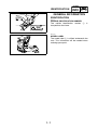
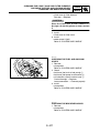
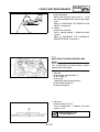
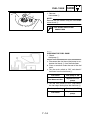
VEHICLE IDENTIFICATION NUMBER
The vehicle identification number 1
stamped into the frame.
is
1
EAS00018
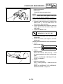
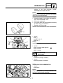
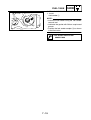
MODEL LABEL
The model label 1 is affixed underneath the
seat. This information will be needed when
ordering spare parts.
1
1-1
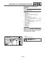
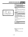
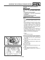
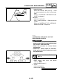
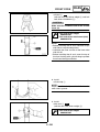
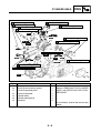
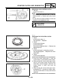
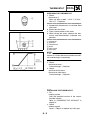
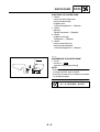
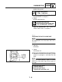
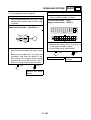
MULTI-FUNCTION DISPLAY
GEN
INFO
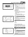
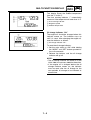
MULTI-FUNCTION DISPLAY
The multi-function display is equipped with the
following:
• an odometer (which shows the total distance traveled)
• two tripmeters (which show the distance
traveled since they were last set to zero, the
time passed since the tripmeters were set
to zero, and the average speed traveled
during this time)
1 “MODE” button
2 Multi-function display
3 “SET” button
• a fuel reserve tripmeter (which shows the
distance traveled since the fuel level warning light came on)
• a clock
• an ambient temperature display
• an oil change indicator (which comes on
when the engine oil should be changed)
NOTE:
• For the UK, the distance traveled is displayed in miles and the temperature reading
is displayed in °F.
• For other countries, the distance traveled is
displayed in kilometers and the temperature
reading is displayed in °C.
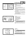
1 Total
2 Trip 1
3 Trip 2
4 Trip/Fuel
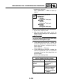
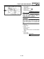
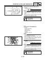
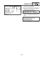
Odometer and tripmeter modes
Pushing the “MODE” button switches the display between the odometer mode “Total” and
the tripmeter modes “Trip” in the following
order:
Total → Trip 1 → Trip 2 → Trip/fuel → Total
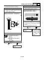
1 Distance
2 Time
3 Average speed
NOTE:
• The Trip/fuel odometer is only activated if the
fuel level warning light comes on.
• The Trip 2 odometer is automatically reset
after turning the key to “OFF” and two hours
have passed.
1-2
MULTI-FUNCTION DISPLAY
GEN
INFO
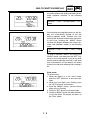
Pushing the “SET” button when in the tripmeter mode switches the display between the different tripmeter functions in the following
order:
Distance → Time → Average speed → Distance
If the fuel level warning light comes on, the display will automatically change to the fuel
reserve tripmeter mode “Trip/fuel” and start
counting the distance traveled from that point.
In that case, pushing the “MODE” button
switches the display between the various tripmeter and odometer modes in the following
order:
Trip/Fuel → Trip 1 → Trip 2 → Total → Trip/
fuel
To reset a tripmeter, select it by pushing the
“MODE” button, and then push the “SET” button for at least one second. If you do not reset
the fuel reserve tripmeter manually, it will reset
itself automatically and the display will return
to the prior mode after refueling and traveling 5
km.
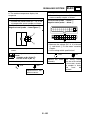
Clock mode
To set the clock:
1. When the display is in the “Total” mode,
push the “SET” button for at least two seconds.
2. When the hour digits start flashing, push
the “SET” button to set the hours.
3. Push the “MODE” button, and the minute
digits will start flashing.
4. Push the “SET” button to set the minutes.
5. Push the “MODE” button and then release it
to start the clock. The display will return to
the “Total” mode.
1-3
MULTI-FUNCTION DISPLAY
GEN
INFO
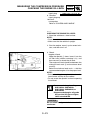
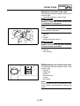
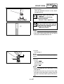
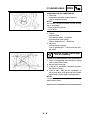
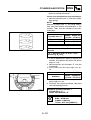
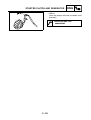
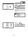
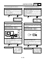
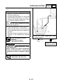
Ambient temperature display
This display shows the ambient temperature
from -30 °C to 50 °C.
The frost warning indicator “*” automatically
comes on if the temperature is lower than 3 °C.
1 Frost warning indicator
2 Negative symbol
3 Ambient temperature
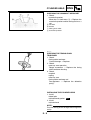
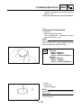
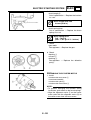
Oil change indicator “OIL”
The engine oil should be changed when this
indicator comes on. The indicator stays on
until it is reset. After changing the engine oil,
reset the indicator as follows.
1 Oil change indicator “OIL”
To reset the oil change indicator:
1. Set the main switch to “ON” while holding
the “MODE” and “SET” buttons pushed for
two to five seconds.
2. Release the buttons, and the oil change
indicator will go off.
NOTE:
• The oil change indicator will come on at the
initial 1000 km and every 3000 km thereafter.
• If the engine oil is changed before the oil
change indicator comes on, the indicator
must be reset after the oil change for the
next periodic oil change to be indicated at
correct time.
1-4
IMPORTANT INFORMATION
GEN
INFO
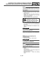
EAS00020
IMPORTANT INFORMATION
PREPARATION FOR REMOVAL AND
DISASSEMBLY
1. Before removal and disassembly, remove all
dirt, mud, dust and foreign material.
2. Use only the proper tools and cleaning
equipment.
Refer to “SPECIAL TOOLS”.
3. When disassembling, always keep mated
parts together. This includes gears, cylinders, pistons and other parts that have been
“mated” through normal wear. Mated parts
must always be reused or replaced as an
assembly.
4. During disassembly, clean all of the parts
and place them in trays in the order of disassembly. This will speed up assembly and
allow for the correct installation of all parts.
5. Keep all parts away from any source of fire.
EAS00021
REPLACEMENT PARTS
Use only genuine Yamaha parts for all
replacements. Use oil and grease recommended by Yamaha for all lubrication jobs.
Other brands may be similar in function and
appearance, but inferior in quality.
EAS00022
GASKETS, OIL SEALS AND O-RINGS
1. When overhauling the engine, replace all
gaskets, seals and O-rings. All gasket surfaces, oil seal lips and O-rings must be
cleaned.
2. During reassembly, properly oil all mating
parts and bearings and lubricate the oil seal
lips with grease.
1-5
IMPORTANT INFORMATION
GEN
INFO
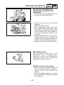
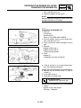
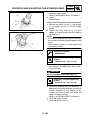
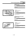
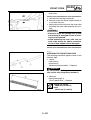
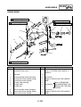
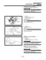
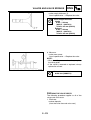
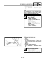
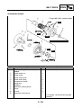
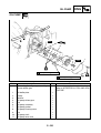
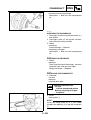
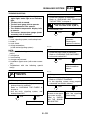
EAS00023
LOCK WASHERS/PLATES AND COTTER
PINS
After removal, replace all lock washers/plates
1 and cotter pins. After the bolt or nut has
been tightened to specification, bend the lock
tabs along a flat of the bolt or nut.
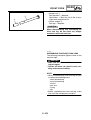
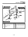
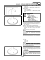
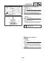
EAS00024
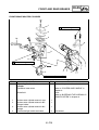
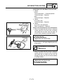
BEARINGS AND OIL SEALS
Install bearings and oil seals so that the manufacturer’s marks or numbers are visible. When
installing oil seals, lubricate the oil seal lips
with a light coat of lithium-soap-based grease.
Oil bearings liberally when installing, if appropriate.
1 Oil seal
CAUTION:
_
Do not spin the bearing with compressed
air because this will damage the bearing
surfaces.
2 Bearing
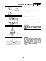
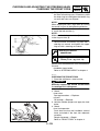
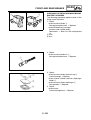
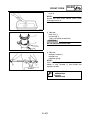
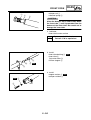
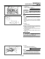
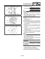
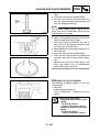
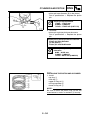
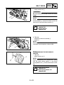
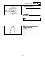
EAS00025
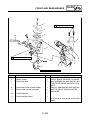
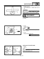
CIRCLIPS
Before reassembly, check all circlips carefully
and replace damaged or distorted circlips.
Always replace piston pin clips after one use.
When installing a circlip 1, make sure the
sharp-edged corner 2 is positioned opposite
the thrust 3 that the circlip receives.
4 Shaft
1-6
CHECKING THE CONNECTIONS
GEN
INFO
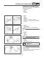
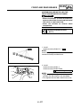
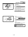
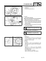
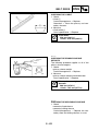
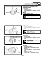
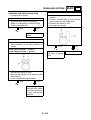
EAS00026
CHECKING THE CONNECTIONS
Check the leads, couplers, and connectors for
stains, rust, moisture, etc.
1. Disconnect:
• lead
• coupler
• connector
2.
•
•
•
Check:
lead
coupler
connector
Moisture → Dry with an air blower.
Rust/stains → Connect and disconnect several times.
3. Check:
• all connections
Loose connection → Connect properly.
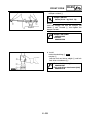
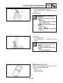
NOTE:
If the pin 1 on the terminal is flattened, bend it
up.
_
4.
•
•
•
Connect:
lead
coupler
connector
NOTE:
Make sure all connections are tight.
_
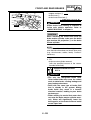
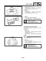
5. Check:
• continuity
(with the pocket tester)
Pocket tester
90890-03112
NOTE:
• If there is no continuity, clean the terminals.
• When checking the wire harness, perform
steps (1) to (3).
• As a quick remedy, use a contact revitalizer
available at most part stores.
_
1-7
SPECIAL TOOLS
GEN
INFO
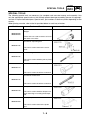
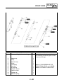
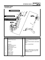
EAS00027
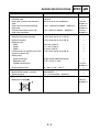
SPECIAL TOOLS
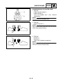
The following special tools are necessary for complete and accurate tune-up and assembly. Use
only the appropriate special tools as this will help prevent damage caused by the use of inappropriate tools or improvised techniques. Special tools, part numbers or both may differ depending on the
country.
When placing an order, refer to the list provided below to avoid any mistakes.
Tool No.
Tool name/Function
Slide hammer bolt
Weight
90890-01083
90890-01084
These tools are used to remove or install
the rocker arm shafts.
Crankshaft separating tool
90890-01135
This tool is used to remove the crankshaft.
Rotor holding tool
90890-01235
This tool is used to hold the primary fixed
sheave.
Crankshaft installer pot
90890-01274
This tool is used to install the crankshaft.
Crankshaft installer bolt
90890-01275
This tool is used to install the crankshaft.
Damper rod holder
90890-01294
This tool is used to hold the damper rod
when removing or installing the damper
rod.
Piston pin puller set
90890-01304
This tool is used to remove the piston
pins.
1-8
Illustration
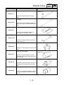
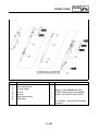
SPECIAL TOOLS
Tool No.
Tool name/Function
Tappet adjusting tool
90890-01311
This tool is used to adjust valve clearance.
T-handle
90890-01326
This tool is used to hold the damper rod
when removing or installing the damper
rod.
Clutch spring holder
90890-01337
This tool is used to disassembly and
assembly the secondary sheave.
Locknut wrench
90890-01348
This tool is used to remove or install the
clutch carrier nut.
Flywheel puller
90890-01362
This tool is used to remove the generator
rotor.
Fork seal driver weight
90890-01367
This tool is used to install the oil seal,
dust seal, and the outer tube bushing of a
front fork leg.
Fork seal driver attachment (ø36)
90890-01370
This tool is used to install the oil seal and
the outer tube bushing of the front fork
leg.
Oil seal guide (ø41)
90890-01396
This tool is used for protecting the oil seal
lip when installing the secondary sliding
sheave.
1-9
GEN
INFO
Illustration
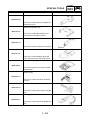
SPECIAL TOOLS
Tool No.
Tool name/Function
Steering nut wrench
90890-01403
This tool is used to loosen or tighten the
steering ring nuts.
Clutch spring holder arm
90890-01464
This tool is used to disassembly and
assembly the secondary sheave.
Adapter (M14)
90890-01478
This tool is used to install the crankshaft.
Sheave holder
90890-01701
This tool is used to hold the generator
rotor, clutch housing, and clutch carrier.
Compression gauge
90890-03081
This tool is used to measure the engine
compression.
Pocket tester
90890-03112
This tool is used to check the electrical
system.
Exhaust attachment
90890-03134
This tool is used to measure the CO density.
Timing light
90890-03141
This tool is used to check the ignition timing.
1 - 10
GEN
INFO
Illustration
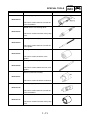
SPECIAL TOOLS
Tool No.
Tool name/Function
Valve spring compressor
90890-04019
This tool is used to remove or install the
valve assemblies.
Middle driven shaft bearing driver
90890-04058
This tool is used to install the water pump
seal.
Valve guide remover (ø6)
90890-04064
This tool is used to remove or install the
valve guides.
Valve guide installer (ø6)
90890-04065
This tool is used to install the valve
guides.
Valve guide reamer (ø6)
90890-04066
This tool is used to rebore the new valve
guides.
Spacer (crankshaft installer)
90890-04081
This tool is used to install the crankshaft.
Valve spring compressor attachment
90890-04108
This tool is used to remove or install the
valve assemblies.
Mechanical seal installer
90890-04132
This tool is used to install the water pump
seal.
1 - 11
GEN
INFO
Illustration
SPECIAL TOOLS
Tool No.
Tool name/Function
Ignition checker
90890-06754
This tool is used to check the ignition system components.
Vacuum/pressure pump gauge set
90890-06756
This tool is used to check the air cut-off
valve.
Fuel sender removal tool
90890-11098
This tool are used to remove the fuel
sender.
Yamaha bond No. 1215
90890-85505
This bond is used to seal two mating surfaces (e.g., crankcase mating surfaces).
1 - 12
GEN
INFO
Illustration
SPEC
CHAPTER 2
SPECIFICATIONS
GENERAL SPECIFICATIONS ........................................................................ 2-1
ENGINE SPECIFICATIONS ............................................................................2-2
CHASSIS SPECIFICATIONS ........................................................................2-11
ELECTRICAL SPECIFICATIONS .................................................................2-15
CONVERSION TABLE .................................................................................. 2-18
GENERAL TIGHTENING TORQUE SPECIFICATIONS...............................2-18
TIGHTENING TORQUES .............................................................................. 2-19
ENGINE TIGHTENING TORQUES......................................................... 2-19
CHASSIS TIGHTENING TORQUES.......................................................2-21
LUBRICATION POINTS AND LUBRICANT TYPES .................................... 2-23
ENGINE LUBRICATION POINTS AND LUBRICANT TYPES ................ 2-23
CHASSIS LUBRICATION POINTS AND LUBRICANT TYPES .............. 2-24
COOLING SYSTEM DIAGRAMS .................................................................. 2-25
CABLE ROUTING ......................................................................................... 2-26
GENERAL SPECIFICATIONS
SPEC
SPECIFICATIONS
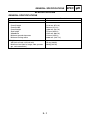
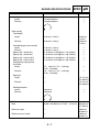
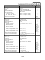
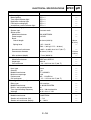
GENERAL SPECIFICATIONS
Item
Standard
Model code
Dimensions
Overall length
Overall width
Overall height
Seat height
Wheelbase
Minimum ground clearance
Minimum turning radius
Weight
Wet (with oil and a full fuel tank)
Maximum load (total of cargo, rider, passenger, and accessories)
1C01
2,210 mm (87.0 in)
790 mm (31.1 in)
1,380 mm (54.3 in)
775 mm (30.5 in)
1,545 mm (60.8 in)
113 mm (4.45 in)
3,600 mm (143.7 in)
176 kg (388 lb)
180 kg (397 lb)
2-1
ENGINE SPECIFICATIONS
SPEC
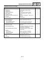
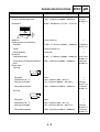
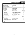
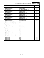
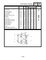
ENGINE SPECIFICATIONS
Item
Engine
Engine type
Displacement
Cylinder arrangement
Bore × stroke
Compression ratio
Standard compression pressure (at
sea level)
Starting system
Fuel
Recommended fuel
Fuel tank capacity
Total (including reserve)
Fuel reserve amount
Engine oil
Lubrication system
Recommended oil type
Recommended engine oil grade
Quantity
Total amount
Periodic oil change
Oil temperature
Final transmission oil
Type
Oil quantity
Standard
Limit
Liquid cooled 4-stroke, SOHC
249.7 cm3
Forward-inclined single cylinder
69.0 × 66.8 mm (2.72 × 2.63 in)
10.00 :1
1,400 kPa (14.0 kgf/cm2, 199.1 psi) at
500 r/min
Electric starter
-------------------
Regular unleaded gasoline only
----
13.0 L (2.86 Imp.gal, 3.43 US gal)
2.0 L (0.44 Imp.gal, 0.53 US gal)
-------
Wet sump
SAE10W30, SAE10W40, SAE15W40,
SAE20W40, or SAE20W50
API service SG type or higher, JASO
standard MA
-------
1.40 L (1.23 Imp.qt, 1.48 US qt)
1.20 L (1.06 Imp.qt, 1.27 US qt)
65 ~ 75 °C (149 ~ 167 °F)
----------
SAE10W30 type SE motor oil
0.25 L (0.22 Imp.qt, 0.26 US qt)
-------
2-2
----
----
ENGINE SPECIFICATIONS
Item
Oil pump
Oil pump type
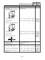
Inner-rotor-to-outer-rotor-tip clearance
Outer-rotor-to-oil-pump-housing
clearance
Oil-pump-housing-to-inner-andouter-rotor clearance
Cooling system
Radiator and engine capacity
Radiator capacity
Radiator core
Width
Height
Depth
Coolant reservoir capacity (up to the
maximum level mark)
Water pump
Water pump type
Reduction ratio
Impeller shaft tilt limit
Coolant temperature
Spark plug
Manufacturer/model × quantity
Spark plug gap
Cylinder head
Maximum warpage
SPEC
Standard
Trochoid
Less than 0.15 mm (0.0059 in)
0.013 ~ 0.036 mm (0.0005 ~ 0.0014 in)
0.04 ~ 0.09 mm (0.0016 ~ 0.0035 in)
Limit
---0.23 mm
(0.0091 in)
0.106 mm
(0.0042 in)
0.16 mm
(0.0063 in)
0.70 L (0.62 Imp.qt, 0.74 US qt)
0.34 L (0.30 Imp.qt, 0.36 US qt)
-------
229.0 mm (9.02 in)
111.5 mm (4.39 in)
33.0 mm (1.30 in)
0.26 L (0.23 Imp.qt, 0.28 US qt)
-------------
Single suction centrifugal pump
37/22 × 25/37 (1.136)
---80 ~ 90 °C (176 ~ 194 °F)
NGK/DR8EA × 1
0.6 ~ 0.7 mm (0.024 ~ 0.028 in)
----
------0.15 mm
(0.0059 in)
---------0.05 mm
(0.0020 in)
2-3
ENGINE SPECIFICATIONS
Item
Standard
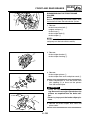
Camshaft
Drive system
Intake camshaft lobe dimensions
Chain drive (left)
SPEC
Limit
----
A
B
Measurement A
37.051 ~ 37.151 mm (1.4587 ~ 1.4626 in) 36.956 mm
(1.4550 in)
30.074 ~ 30.174 mm (1.1840 ~ 1.1880 in) 29.973 mm
(1.1800 in)
Measurement B
Exhaust camshaft lobe dimensions
A
B
Measurement A
Measurement B
Maximum camshaft runout
Timing chain
Model/number of links
Tensioning system
Rocker arms/rocker arm shafts
Rocker arm inside diameter
Rocker arm shaft outside diameter
Rocker-arm-to-rocker-arm-shaft
clearance
37.053 ~ 37.153 mm (1.4588 ~ 1.4627 in) 36.956 mm
(1.4550 in)
30.091 ~ 30.191 mm (1.1847 ~ 1.1886 in) 29.194 mm
(1.1494 in)
---0.030 mm
(0.0012 in)
DID SC.A-0404A SV/104
Automatic
-------
12.000 ~ 12.018 mm (0.4724 ~ 0.4731 in) 12.030 mm
(0.4736 in)
11.981 ~ 11.991 mm (0.4717 ~ 0.4721 in) 11.950 mm
(0.4705 in)
0.009 ~ 0.037 mm (0.0004 ~ 0.0015 in)
0.080 mm
(0.0031 in)
2-4
ENGINE SPECIFICATIONS
Item
SPEC
Standard
Valves, valve seats, valve guides
Valve clearance (cold)
Intake
Exhaust
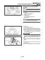
Valve dimensions
Limit
0.08 ~ 0.12 mm (0.0031 ~ 0.0047 in)
0.16 ~ 0.20 mm (0.0063 ~ 0.0079 in)
B
-------
C
D
A
Head Diameter
Face Width
Valve head diameter A
Intake
Exhaust
Valve face width B
Intake
Exhaust
Valve seat width C
Intake
Exhaust
Valve margin thickness D
Intake
Exhaust
Valve stem diameter
Intake
Exhaust
Valve guide inside diameter
Intake
Exhaust
Valve-stem-to-valve-guide clearance
Intake
Exhaust
Seat Width
Margin Thickness
33.90 ~ 34.10 mm (1.3346 ~ 1.3425 in)
28.40 ~ 28.60 mm (1.1181 ~ 1.1260 in)
-------
3.394 ~ 3.960 mm (0.1336 ~ 0.1559 in)
3.394 ~ 3.960 mm (0.1336 ~ 0.1559 in)
-------
0.90 ~ 1.10 mm (0.0354 ~ 0.0433 in)
0.90 ~ 1.10 mm (0.0354 ~ 0.0433 in)
0.80 ~ 1.20 mm (0.0315 ~ 0.0472 in)
0.80 ~ 1.20 mm (0.0315 ~ 0.0472 in)
5.975 ~ 5.990 mm (0.2352 ~ 0.2358 in)
5.960 ~ 5.975 mm (0.2346 ~ 0.2352 in)
6.000 ~ 6.012 mm (0.2362 ~ 0.2367 in)
6.000 ~ 6.012 mm (0.2362 ~ 0.2367 in)
0.010 ~ 0.037 mm (0.0004 ~ 0.0015 in)
0.025 ~ 0.052 mm (0.0010 ~ 0.0020 in)
2-5
1.6 mm
(0.06 in)
1.6 mm
(0.06 in)
0.5 mm
(0.02 in)
0.5 mm
(0.02 in)
5.940 mm
(0.2339 in)
5.920 mm
(0.2331 in)
6.050 mm
(0.2382 in)
6.050 mm
(0.2382 in)
0.080 mm
(0.0031 in)
0.100 mm
(0.0039 in)
ENGINE SPECIFICATIONS
Item
SPEC
Standard
Limit
Valve stem runout
----
0.010 mm
(0.0004 in)
Cylinder head valve seat width
Intake
0.90 ~ 1.10 mm (0.0354 ~ 0.0433 in)
1.6 mm
(0.06 in)
1.6 mm
(0.06 in)
Exhaust
Valve springs
Inner spring
Free length
Intake
Exhaust
Installed length (valve closed)
Intake
Exhaust
Spring rate - intake (K1)
Spring rate - intake (K2)
Spring rate - exhaust (K1)
Spring rate - exhaust (K2)
Compression spring force
(installed)
Intake
Exhaust
0.90 ~ 1.10 mm (0.0354 ~ 0.0433 in)
38.10 mm (1.50 in)
38.10 mm (1.50 in)
36.10 mm
(1.42 in)
36.10 mm
(1.42 in)
30.10 mm (1.19 in)
30.10 mm (1.19 in)
10.29 N/mm (1.05 kgf/mm, 58.75 lb/in)
13.37 N/mm (1.36 kgf/mm, 76.34 lb/in)
10.29 N/mm (1.05 kgf/mm, 58.75 lb/in)
13.37 N/mm (1.36 kgf/mm, 76.34 lb/in)
-------------------
76 ~ 88 N
(7.80 ~ 9.00 kgf, 17.20 ~ 19.85 lbf)
76 ~ 88 N
(7.80 ~ 9.00 kgf, 17.20 ~ 19.85 lbf)
-------
Spring tilt
Intake
----
Exhaust
----
2.5°/1.7 mm
(2.5°/0.067 in)
2.5°/1.7 mm
(2.5°/0.067 in)
2-6
ENGINE SPECIFICATIONS
Item
Winding direction (top view)
Intake
Exhaust
Outer spring
Free length
Intake
Exhaust
Installed length (valve closed)
Intake
Exhaust
Spring rate - intake (K1)
Spring rate - intake (K2)
Spring rate - exhaust (K1)
Spring rate - exhaust (K2)
Compression spring force
(installed)
Intake
Exhaust
Standard
Counterclockwise
Counterclockwise
36.93 mm (1.45 in)
36.93 mm (1.45 in)
-------
35.00 mm
(1.38 in)
35.00 mm
(1.38 in)
-------------------
115 ~ 133 N (11.73 ~ 13.56 kgf,
25.85 ~ 29.90 lbf)
115 ~ 133 N (11.73 ~ 13.56 kgf,
25.85 ~ 29.90 lbf)
----
----
Exhaust
----
Cylinder
Bore
Limit
31.60 mm (1.24 in)
31.60 mm (1.24 in)
23.18 N/mm (2.36 kgf/mm, 132.36 lb/in)
31.66 N/mm (3.23 kgf/mm, 180.78 lb/in)
23.18 N/mm (2.36 kgf/mm, 132.36 lb/in)
31.66 N/mm (3.23 kgf/mm, 180.78 lb/in)
Spring tilt
Intake
Winding direction
Intake
Exhaust
SPEC
2.5°/1.6 mm
(2.5°/0.063 in)
2.5°/1.6 mm
(2.5°/0.063 in)
Clockwise
Clockwise
69.000 ~ 69.005 mm (2.7165 ~ 2.7167 in)
Maximum taper
----
Maximum out of round
----
----
2-7
-------
69.100 mm
(2.7205 in)
0.050 mm
(0.0020 in)
0.030 mm
(0.0012 in)
ENGINE SPECIFICATIONS
Item
SPEC
Standard
Piston
Piston-to-cylinder clearance
Limit
0.020 ~ 0.040 mm (0.0008 ~ 0.0016 in)
0.15 mm
(0.0059 in)
68.965 ~ 68.980 mm (2.7152 ~ 2.7157 in)
----
Diameter D
H
D
Height H
Piston pin bore (in the piston)
Diameter
5.0 mm (0.20 in)
----
17.004 ~ 17.015 mm (0.6694 ~ 0.6699 in) 17.045 mm
(0.6711 in)
0.50 mm (0.0197 in)
---Intake side
----
Offset
Offset direction
Piston pin
Outside diameter
Piston-pin-to-piston-pin-bore clearance
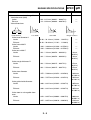
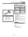
Piston rings
Top ring
16.991 ~ 17.000 mm (0.6689 ~ 0.6693 in) 16.971 mm
(0.6681 in)
0.004 ~ 0.024 mm (0.0002 ~ 0.0009 in)
0.074 mm
(0.0029 in)
B
T
Ring type
Dimensions (B × T)
End gap (installed)
Barrel
1.00 × 2.60 mm (0.04 × 0.10 in)
0.15 ~ 0.30 mm (0.0059 ~ 0.0118 in)
Ring side clearance
0.040 ~ 0.080 mm (0.0016 ~ 0.0031 in)
------0.45 mm
(0.0177 in)
0.120 mm
(0.0047 in)
2nd ring
B
T
Ring type
Dimensions (B × T)
End gap (installed)
Taper
1.00 × 2.90 mm (0.04 × 0.11 in)
0.30 ~ 0.45 mm (0.0118 ~ 0.0177 in)
Ring side clearance
0.030 ~ 0.070 mm (0.0012 ~ 0.0028 in)
2-8
------0.70 mm
(0.0276 in)
0.120 mm
(0.0047 in)
ENGINE SPECIFICATIONS
Item
SPEC
Standard
Limit
Oil ring
B
T
Dimensions (B × T)
End gap (installed)
Ring side clearance
Crankshaft
C
1.50 × 2.50 mm (0.06 × 0.10 in)
0.20 ~ 0.70 mm (0.0079 ~ 0.0276 in)
0.060 ~ 0.150 mm (0.0024 ~ 0.0059 in)
----------
C
E
D
A
Width A
Maximum runout C
Big end side clearance D
Big end radial clearance E
Automatic centrifugal clutch
Clutch type
Clutch shoe thickness
59.75 ~ 59.80 mm (2.352 ~ 2.354 in)
---0.350 ~ 0.850 mm (0.0138 ~ 0.0335 in)
0.010 ~ 0.025 mm (0.0004 ~ 0.0010 in)
Dry, centrifugal automatic
3.3 mm (0.13 in)
Clutch shoe spring free length
Clutch housing inside diameter
31.3 mm (1.23 in)
145.0 mm (5.71 in)
Compression spring free length
102.4 mm (4.03 in)
Primary sheave weight outside diameter
Clutch-in revolution
Clutch-stall revolution
V-belt
V-belt width
Transmission
Transmission type
Primary reduction system
Primary reduction ratio
Secondary reduction system
Secondary reduction ratio
Operation
Single speed automatic
20.0 mm (0.79 in)
2,250 ~ 2,850 r/min
3,700 ~ 4,700 r/min
23.0 mm (0.91 in)
V-belt automatic
Helical gear
40/15 (2.666)
Helical gear
40/14 (2.857)
Centrifugal automatic type
2.44 ~ 0.83 : 1
2-9
---0.030 mm
(0.0012 in)
---------2.0 mm
(0.08 in)
---145.5 mm
(5.73 in)
90.0 mm
(3.54 in)
19.5 mm
(0.77 in)
------21.0 mm
(0.83 in)
----------------------
ENGINE SPECIFICATIONS
Item
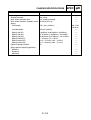
Air filter
Air filter element
Fuel pump
Pump type
Model/manufacturer
Output pressure
Carburetor
Type × quantity
Manufacturer
ID mark
Main jet
Main air jet
Jet needle
Needle jet
Pilot air jet 1
Pilot outlet
Pilot jet
Bypass 1
Bypass 2
Bypass 3
Bypass 4
Pilot screw turns out
Valve seat size
Starter jet 1
Throttle valve size
Float height
Idling condition
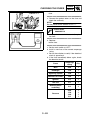
Engine idling speed
CO density (when air induction system is operating)
CO density (when air induction system is not operating)
Throttle cable free play
Standard
SPEC
Limit
Oil-coated paper element
----
Electrical
2GV0/MITSUBISHI
12.5 kPa (0.13 kgf/cm2, 1.8 psi)
----------
1C0 × 1
KEIHIN
1C0D
#122
#90
N425-DVD00
2.6
#125
0.85
#35
0.7
0.7
0.7
0.7
2
1.6
#38
10
17.5 mm (0.69 in)
----------------------------------------------------------
1,550 ~ 1,650 r/min
4.0%
-------
6.0%
----
4.0 ~ 6.0 mm (0.16 ~ 0.24 in)
----
2 - 10
CHASSIS SPECIFICATIONS
SPEC
CHASSIS SPECIFICATIONS
Item
Frame
Frame type
Caster angle
Trail
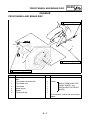
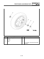
Front wheel
Wheel type
Rim
Size
Material
Wheel travel
Wheel runout
Maximum radial wheel runout
Maximum lateral wheel runout
Wheel axle bending limit
Rear wheel
Wheel type
Rim
Size
Material
Wheel travel
Wheel runout
Maximum radial wheel runout
Maximum lateral wheel runout
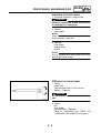
Front tire
Tire type
Size
Manufacturer/model
Tire pressure (cold)
0 ~ 90 kg (0 ~ 198 lb)
90 ~ 235 kg (198 ~ 518 lb)
Maximum tire tread depth
Standard
Limit
Steel tube underbone
28.00°
100.0 mm (3.94 in)
----------
Cast wheel
----
15 × MT3.50
Aluminum
94.0 mm (3.70 in)
----------
----
1.0 mm
(0.04 in)
0.5 mm
(0.02 in)
0.03 mm
(0.0012 in)
-------
Cast wheel
----
14 × MT3.75
Aluminum
83.0 mm (3.27 in)
----------
----
1.0 mm
(0.04 in)
0.5 mm
(0.02 in)
----
Tubeless
120/70-15 M/C 56S or 56P
MICHELIN/GOLD STANDARD
PIRELLI/GTS23
190 kPa (1.90 kgf/cm2, 28 psi)
210 kPa (2.10 kgf/cm2, 30 psi)
----
2 - 11
----------
------1.6 mm
(0.06 in)
CHASSIS SPECIFICATIONS
Item
Rear tire
Tire type
Size
Manufacturer/model
Tire pressure (cold)
0 ~ 90 kg (0 ~ 198 lb)
90 ~ 180 kg (198 ~ 397 lb)
Maximum tire tread depth
Front brake
Brake type
Operation
Recommended fluid
Brake disc
Diameter × thickness
Minimum thickness
Standard
Tubeless
140/70-14 M/C 68S or 68P
MICHELIN/GOLD STANDARD
PIRELLI/GTS24
220 kPa (2.20 kgf/cm2, 32 psi)
250 kPa (2.50 kgf/cm2, 36 psi)
----
Single disc brake
Right hand operation
DOT 4
267.0 × 5.0 mm (10.51 × 0.20 in)
----
Maximum deflection
----
Brake pad lining thickness (inner)
4.5 mm (0.18 in)
Brake pad lining thickness (outer)
4.5 mm (0.18 in)
Master cylinder inside diameter
Caliper cylinder inside diameter
Rear brake
Brake type
Operation
Recommended fluid
Brake disc
Diameter × thickness
Minimum thickness
12.70 mm (0.50 in)
25.00 mm × 1 and 28.00 mm × 1 (0.98 in
× 1 and 1.10 in × 1)
Single disc brake
Left hand operation
DOT 4
240.0 × 5.0 mm (9.45 × 0.20 in)
----
Maximum deflection
----
Brake pad lining thickness (inner)
5.3 mm (0.21 in)
Brake pad lining thickness (outer)
5.3 mm (0.21 in)
Master cylinder inside diameter
Caliper cylinder inside diameter
SPEC
11.0 mm (0.43 in)
22.20 mm × 2 (0.87 in × 2)
2 - 12
Limit
----------
------1.6 mm
(0.06 in)
------------4.5 mm
(0.18 in)
0.20 mm
(0.0079 in)
0.5 mm
(0.02 in)
0.5 mm
(0.02 in)
-------
------------4.5 mm
(0.18 in)
0.20 mm
(0.0079 in)
0.8 mm
(0.03 in)
0.8 mm
(0.03 in)
-------
CHASSIS SPECIFICATIONS
Item
Steering
Steering bearing type
Center to lock angle (left)
Center to lock angle (right)
Front suspension
Suspension type
Front fork type
Front fork travel
Spring
Free length
SPEC
Standard
Limit
Angular bearing
62.0°
62.0°
----------
Telescopic fork
Coil spring/oil damper
110.0 mm (4.33 in)
----------
308.0 mm (12.126 in)
Installed length
Spring rate (K1)
Spring rate (K2)
Spring stroke (K1)
Spring stroke (K2)
Inner tube outer diameter
Inner tube bending limit
277.4 mm (10.921 in)
8.00 N/mm (0.82 kgf/mm, 45.68 lb/in)
13.60 N/mm (1.39 kgf/mm, 77.65 lb/in)
0 ~ 80.0 mm (0 ~ 3.15 in)
80.0 ~ 110.0 mm (3.15 ~ 4.33 in)
36.0 mm (1.42 in)
----
Optional spring available
Fork oil
Recommended oil
Quantity (each front fork leg)
Level (from the top of the inner
tube, with the inner tube fully compressed, and without the fork
spring)
No
Fork oil 15W or equivalent
195.0 cm3 (6.86 Imp.oz, 6.59 US oz)
105.0 mm (4.13 in)
2 - 13
301.87 mm
(11.885 in)
------------------0.2 mm
(0.008 in)
-------------
CHASSIS SPECIFICATIONS
Item
Rear suspension
Suspension type
Rear shock absorber type
Rear shock absorber assembly travel
Spring
Free length
Installed length
Spring rate (K1)
Spring rate (K2)
Spring rate (K3)
Spring stroke (K1)
Spring stroke (K2)
Spring stroke (K3)
Optional spring available
Spring preload adjusting positions
Minimum
Standard
Maximum
SPEC
Standard
Unit swing
Coil spring/oil damper
95.0 mm (3.74 in)
270.1 mm (10.63 in)
249 mm (9.80 in)
8.00 N/mm (0.82 kgf/mm, 45.68 lb/in)
13.70 N/mm (1.40 kgf/mm, 78.23 lb/in)
20.30 N/mm (2.07 kgf/mm, 115.91 lb/in)
0 ~ 42.0 mm (0 ~ 1.65 in)
42.0 ~ 72.5 mm (1.65 ~ 2.85 in)
72.5 ~ 95.0 mm (2.85 ~ 3.74 in)
No
1
1
4
Limit
---------264.7 mm
(10.42 in)
----------------------------------
2 - 14
ELECTRICAL SPECIFICATIONS
SPEC
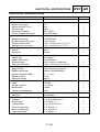
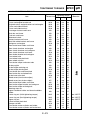
ELECTRICAL SPECIFICATIONS
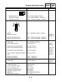
Item
System voltage
Ignition system
Ignition system type
Ignition timing (B.T.D.C.)
Advancer type
Pickup coil resistance
CDI unit model/manufacturer
Ignition coil
Model/manufacturer
Minimum ignition spark gap
Primary coil resistance
Secondary coil resistance
Spark plug cap
Material
Resistance
Charging system
System type
Model/manufacturer
Standard output
Stator coil resistance
Rectifier/regulator
Regulator type
Model/manufacturer
No-load regulated voltage
Rectifier capacity
Withstand voltage
Battery
Model
Voltage, capacity
Manufacturer
Ten hour rate amperage
Headlight
Bulb type
Bulb (voltage, wattage × quantity)
Headlight
Auxiliary light
Tail/brake light
Front turn signal light
Rear turn signal light
License plate light
Standard
Limit
12 V
CDI
10.0°
Digital
130 ~ 150 Ω
5510-F/MITSUBA
-------------------
4719/MITSUBA
6 mm (0.24 in)
0.225 ~ 0.275 Ω at 25 °C (77 °F)
1.89 ~ 2.31 kΩ at 25 °C (77 °F)
-------------
Resin
10.0 kΩ
-------
AC magneto
5425-H/Mitsuba
14.0 V, 235 W at 5,000 r/min
0.385 ~ 0.415 Ω at 20 °C (68 °F)
----------
Semi conductor-short circuit
SH678-11/SHINDENGEN
14.1 ~ 14.9 V
22.0 A
200.0 V
----------------
YTX9-BS
12 V, 8.0 Ah
YUASA
0.8 A
-------------
Halogen bulb
----
12 V, 35.0 W/35.0 W × 2
12 V, 5.0 W × 2
12 V, 5.0 W/21.0 W × 2
12 V, 10.0 W × 2
12 V, 10.0 W × 2
12 V, 5.0 W × 1
-------------------
2 - 15
ELECTRICAL SPECIFICATIONS
Item
Indicator light
Meter lighting
Turn signal indicator light
High beam indicator light
Fuel level warning light
Immobilizer system indicator light
Electric starting system
System type
Starter motor
Model/manufacturer
Power output
Brush
Overall length
Spring force
Armature coil resistance
Commutator diameter
Mica undercut (depth)
Starter relay
Model/manufacturer
Amperage
Coil resistance
Horn
Horn type
Quantity
Model/manufacturer
Maximum amperage
Performance
Coil resistance
Turn signal/hazard relay
Relay type
Model/manufacturer
Built-in, self-canceling device
Turn signal blinking frequency
Wattage
Fuel sender
Model/manufacturer
Sender unit resistance (full)
Sender unit resistance (empty)
Standard
SPEC
Limit
LED × 1
LED × 2
LED × 1
LED × 1
LED × 1
----------------
Constant mesh
----
SM-13/MITSUBA
0.65 kW
-------
10.0 mm (0.39 in)
4.0 mm
(0.16 in)
----
7.65 ~ 10.01 N
(780 ~ 1,021 gf, 27.5 ~ 36.0 oz)
0.0012 ~ 0.0022 Ω at 20 °C (68 °F)
28.0 mm (1.10 in)
0.7 mm (0.028 in)
---27.0 mm
(1.06 in)
----
MS5F-631/JIDECO
180.0 A
4.18 ~ 4.62 Ω at 20 °C (68 °F)
----------
Plane
1 pc
YF-12/NIKKO
3.0 A
105 ~ 113 dB/2 m
1.15 ~ 1.25 Ω at 20 °C (68 °F)
-------------------
Full transistor
01 8610A/GUILERA
No
70.0 ~ 100.0 cycles/min
10 W × 2.0 + 1.2 W
----------------
1C0/BITRON
0~7Ω
90 ~ 103 Ω
----------
2 - 16
ELECTRICAL SPECIFICATIONS
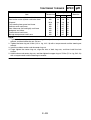
Item
Starting circuit cut-off relay
Model/manufacturer
Coil resistance
Headlight relay
Model/manufacturer
Coil resistance
Fuel pump relay
Model/manufacturer
Coil resistance
Radiator fan motor relay
Model/manufacturer
Coil resistance
Coolant temperature sensor
Model/manufacturer
Resistance at 80 °C (176 °F)
Resistance at 100 °C (212 °F)
Speed sensor
Output voltage
When sensor is on
When sensor is off
Fuses
Main fuse
Headlight fuse
Signaling system fuse
Ignition fuse
Radiator fan motor fuse
CDI unit fuse
Backup fuse (meter assembly)
Reserve fuse
Reserve fuse
Reserve fuse
Reserve fuse
Standard
SPEC
Limit
ACA12115 M02
72 ~ 88 Ω at 20 °C (68 °F)
-------
ACM33211 M05
96 Ω at 20 °C (68 °F)
-------
ACM33211 M05
96 Ω at 20 °C (68 °F)
-------
ACM33211 M05
96 Ω at 20 °C (68 °F)
-------
C40 1734/PRICOL
69.0 Ω
37.2 Ω
----------
DC 4.8 V or more
DC 0.6 V or less
-------
30.0 A
15.0 A
15.0 A
5.0 A
10.0 A
5.0 A
5.0 A
30.0 A
15.0 A
10.0 A
5.0 A
----------------------------------
2 - 17
CONVERSION TABLE/
GENERAL TIGHTENING TORQUE SPECIFICATIONS
SPEC
EAS00028
EAS00029
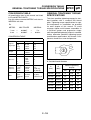
CONVERSION TABLE
GENERAL TIGHTENING TORQUE
SPECIFICATIONS
All specification data in this manual are listed
in SI and METRIC UNITS.
Use this table to convert METRIC unit data to
IMPERIAL unit data.
Ex.
METRIC
MULTIPLIER
IMPERIAL
** mm
×
0.03937
=
** in
2 mm
×
0.03937
=
0.08 in
CONVERSION TABLE
METRIC TO IMPERIAL
Metric unit
m·kg
Tightening torque m·kg
cm·kg
cm·kg
Weight
kg
g
Multiplier
Imperial unit
7.233
86.794
0.0723
0.8679
ft·lb
in·lb
ft·lb
in·lb
2.205
0.03527
lb
oz
Speed
km/hr
0.6214
mph
Distance
km
m
m
cm
mm
0.6214
3.281
1.094
0.3937
0.03937
mi
ft
yd
in
in
Volume/
Capacity
cc (cm3)
cc (cm3)
lt (liter)
lt (liter)
0.03527
0.06102
0.8799
0.2199
oz (IMP lip.)
cu.in
qt (IMP liq.)
gal (IMP liq.)
Misc.
kg/mm
kg/cm2
Centigrade
(°C)
55.997
14.2234
9/5+32
lb/in
psi (lb/in2)
Fahrenheit (°F)
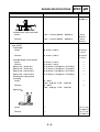
This chart specifies tightening torques for standard fasteners with a standard ISO thread
pitch. Tightening torque specifications for special components or assemblies are provided
for each chapter of this manual. To avoid
warpage, tighten multi-fastener assemblies in
a crisscross pattern and progressive stages
until the specified tightening torque is reached.
Unless otherwise specified, tightening torque
specifications require clean, dry threads. Components should be at room temperature.
A: Distance between flats
B: Outside thread diameter
A
(nut)
2 - 18
B
(bolt)
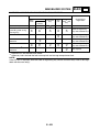
General tightening
torques
Nm
m · kg
ft · lb
10 mm
6 mm
6
0.6
4.3
12 mm
8 mm
15
1.5
11
14 mm
10 mm
30
3.0
22
17 mm
12 mm
55
5.5
40
19 mm
14 mm
85
8.5
61
22 mm
16 mm
130
13.0
94
TIGHTENING TORQUES
SPEC
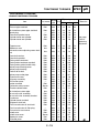
TIGHTENING TORQUES
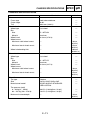
ENGINE TIGHTENING TORQUES
Item
Part name
Thread
Q’ty
size
Tightening torque
Nm m · kg ft · lb
Oil check bolt
Exhaust pipe stud bolt
Air induction system pipe stud bolt
Spark plug
Camshaft sprocket cover
Cylinder head and cylinder
Cylinder head and cylinder
Bolt
Bolt
Bolt
—
Bolt
Nut
Bolt
M6
M8
M6
M12
M6
M8
M6
1
2
2
1
2
4
2
7
13
10
18
10
22
10
0.7
1.3
1.0
1.8
1.0
2.2
1.0
5.1
9.4
7.2
13
7.2
16
7.2
Tappet cover
Generator rotor
Valve clearance adjusting screw locknut
Camshaft retainer
Camshaft sprocket
Timing chain tensioner
Timing chain tensioner cap bolt
Timing chain guide (intake side)
Water pump housing cover
Water pump housing
Coolant drain bolt
Water pump outlet pipe
Thermostat cover
Oil pump assembly
Oil strainer cover
Intake manifold
Carburetor clamp screw
Throttle cable bracket
Air induction system pipe
Air cut-off valve assembly
Air cut-off valve assembly bracket
Crankcase
Cylinder head stud bolt
Engine oil drain bolt
Final transmission oil drain bolt
Final transmission oil filler plug
Transmission case cover
V-belt case
V-belt case cover
Generator cover
Oil baffle plate
Bolt
Nut
M6
M16
5
1
10
80
1.0
8.0
7.2
58
Nut
M6
2
14
1.4
10
Bolt
Bolt
Bolt
Bolt
Bolt
Bolt
Bolt
Bolt
Bolt
Bolt
Bolt
—
Bolt
Screw
Bolt
Nut
Bolt
Bolt
Bolt
Bolt
Bolt
Bolt
—
Bolt
Bolt
Screw
Bolt
Bolt
M6
M10
M6
M8
M6
M6
M6
M6
M6
M6
M6
M35
M6
M6
M5
M6
M6
M6
M6
M8
M12
M8
M14
M8
M6
M6
M6
M6
2
1
2
1
1
2
2
1
2
2
2
1
2
1
2
2
2
2
7
4
1
1
1
6
11
4
10
2
8
60
10
8
10
10
10
10
7
10
7
32
10
2
11
12
10
10
10
13
20
22
3
16
10
7
10
12
0.8
6.0
1.0
0.8
1.0
1.0
1.0
1.0
0.7
1.0
0.7
3.2
1.0
0.2
1.1
1.2
1.0
1.0
1.0
1.3
2.0
2.2
0.3
1.6
1.0
0.7
1.0
1.2
5.8
43
7.2
5.8
7.2
7.2
7.2
7.2
5.1
7.2
5.1
23
7.2
1.4
8.0
8.7
7.2
7.2
7.2
9.4
14
16
1.4
11
7.2
5.1
7.2
8.7
2 - 19
Remarks
See page
2-20 for
tightening
sequence.
LT
TIGHTENING TORQUES
Item
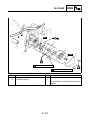
Timing mark accessing plug
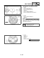
Starter clutch
Secondary sheave
Primary sheave cap
Primary sheave
Clutch carrier
Secondary sheave bracket
Stator coil
Pickup coil
Starter motor
Coolant temperature sensor
Air filter case mounting bolt
Exhaust pipe nut
Muffler mounting bolt
Muffler joint bolt
Coolant reservoir
Radiator
Thermo switch (auto choke)
Thermo switch (radiator fan motor)
Part name
—
Bolt
Nut
Screw
Nut
Nut
Bolt
Bolt
Bolt
Bolt
—
Bolt
Nut
Bolt
Bolt
Bolt
Bolt
—
—
SPEC
Thread
Q’ty
size
Tightening torque
M16
M8
M14
M4
M14
M36
M8
M6
M5
M6
Pt 1/8
M6
M8
M12
M8
M6
M6
M18
M18
8
30
60
3
80
90
22
10
7
10
8
9
20
65
14
7
10
30
30
Cylinder head tightening sequence:
2 - 20
1
3
1
4
1
1
4
3
2
2
1
2
2
3
1
2
2
1
1
Nm m · kg ft · lb
0.8
3.0
6.0
0.3
8.0
9.0
2.2
1.0
0.7
1.0
0.8
0.9
2.0
6.5
1.4
0.7
1.0
3.0
3.0
5.8
22
43
2.2
58
65
16
7.2
5.1
7.2
5.8
6.5
14
47
10
5.1
7.2
22
22
Remarks
LT
LT
LT
LT
LT
TIGHTENING TORQUES
SPEC
CHASSIS TIGHTENING TORQUES
Item
Thread size
Frame and engine bracket
Frame and engine bracket rod
Engine bracket, engine bracket rod and engine
Frame and sidestand bolt
Frame and sidestand nut
Passenger footrest and frame
Grab bar and frame
Fuel tank and frame
Sidestand switch
Battery bracket and frame
Seat lock cable bracket and frame
Swingarm and engine
Rear brake hose holder and frame
Rear shock absorber and engine
Rear shock absorber and swingarm
Rear shock absorber and frame
Rear fender bracket and swingarm
Front wheel axle
Front wheel axle pinch bolt
Rear wheel axle nut
Front brake caliper and outer tube
Brake pad pin
Brake caliper retaining nut
Brake caliper housing bolt
Front brake disc and wheel hub
Rear brake disc and wheel hub
Brake hose union bolt
Bleed screw (front brake caliper)
Bleed screw (rear brake caliper)
Rear brake hose holder and frame
Rear brake caliper bracket and swingarm
Rear brake caliper retaining bolt
Steering stem nut
Upper handlebar holder and lower handlebar
holder
Lower ring nut (initial tightening torque)
Lower ring nut (final tightening torque)
Upper ring nut
Lower bracket pinch bolt
Damper rod bolt
Front brake master cylinder and holder
Front brake master cylinder and brake lever
2 - 21
Tightening torque
Nm m · kg ft · lb
M12
M10
M10
M10
M10
M8
M8
M6
M5
M8
M6
M10
M6
M8
M8
M10
M8
M14
M6
M14
M8
M8
M8
M10
M6
M8
M10
M7
M7
M6
M10
M10
M20
59
64
32
23
40
25
23
7
6
23
10
59
7
18
18
32
16
59
9
135
23
12
22
45
12
23
23
6
6
7
40
27
120
5.9
6.4
3.2
2.3
4.0
2.5
2.3
0.7
0.6
2.3
1.0
5.9
0.7
1.8
1.8
3.2
1.6
5.9
0.9
13.5
2.3
1.2
2.2
4.5
1.2
2.3
2.3
0.6
0.6
0.7
4.0
2.7
12.0
43
46
23
17
29
18
17
5.1
4.3
17
7.2
43
5.1
13
13
23
11
43
6.5
98
17
8.7
16
32
8.7
17
17
4.3
4.3
5.1
29
19
85
M8
23
2.3
17
M25
M25
M25
M8
M10
M6
M6
38
22
75
22
28
7
10
3.8
2.2
7.5
2.2
2.8
0.7
1.0
27
16
54
16
20
5.1
7.2
Remarks
LT
LT
See “NOTE”.
See “NOTE”.
See “NOTE”.
TIGHTENING TORQUES
Item
Thread size
Rear brake master cylinder and holder
Rear brake master cylinder and brake lever
Grip end
Front cowling inner panel and frame
Radiator cover and frame
Rear side cover (left and right) and frame
Mudguard and frame
Footrest board and frame
Storage compartment and frame
M6
M6
M16
M6
M6
M6
M6
M6
M6
SPEC
Tightening torque
Nm m · kg ft · lb
7
10
26
7
7
7
7
7
7
0.7
1.0
2.6
0.7
0.7
0.7
0.7
0.7
0.7
Remarks
5.1
7.2
19
5.1
5.1
5.1
5.1
5.1
5.1
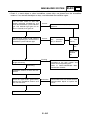
NOTE:
1. Tighten the lower ring nut 38 Nm (3.8 m · kg, 27 ft · lb) with a torque wrench and the steering nut
wrench, and then loosen the nut 1/4 turn.
2. Tighten the lower ring nut 22 Nm (2.2 m · kg, 16 ft · lb) with a torque wrench and the steering nut
wrench.
3. Install the rubber washer and the center ring nut.
4. Finger tighten the center ring nut, align the slots of both ring nuts, and then install the lock
washer.
5. Hold the lower and center ring nuts, and then tighten the upper ring nut 75 Nm (7.5 m · kg, 54 ft · lb)
with a torque wrench and the steering nut wrench.
2 - 22
LUBRICATION POINTS AND LUBRICANT TYPES
SPEC
EAS00031
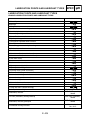
LUBRICATION POINTS AND LUBRICANT TYPES
ENGINE LUBRICATION POINTS AND LUBRICANT TYPES
Lubrication point
Oil seal lips
Lubricant
LS
Bearings
E
O-rings
LS
Cylinder head nut mounting surface
E
Crankshaft pin
E
Connecting rod big end thrust surface
E
Rotary filter inner surface
E
Oil pump drive gear inner surface
E
Timing chain sprocket inner surface
E
Piston pin
E
Piston, ring grooves, and piston rings
E
Cylinder inner surface
E
Camshaft lobes
M
Valve stems (intake and exhaust)
M
Valve stem ends (intake and exhaust)
M
Valve stem seals
M
Rocker arm shafts
E
Rocker arm inner surface
M
Oil pump assembly shaft
E
Oil pump assembly gasket
LS
Oil pump rotors (inner and outer)
E
Starter clutch idle gear thrust surfaces
E
Starter clutch idle gear shaft
E
Starter clutch gear thrust surfaces
E
Starter clutch gear inner surface
E
Main axle thrust surfaces
G
Main and drive axle serration
G
O-ring and collar (clutch housing)
LS
Primary sheave weights
Shell BT grease 3®
Secondary sheave
BEL-RAY assembly
lube®
Oil seal (secondary sliding sheave)
BEL-RAY assembly
lube®
Secondary sheave guide pins
BEL-RAY assembly
lube®
Yamaha bond
No. 1215
Crankcase mating surfaces
2 - 23
LUBRICATION POINTS AND LUBRICANT TYPES
Lubrication point
SPEC
Lubricant
Yamaha bond
No. 1215
Pickup coil/stator assembly lead grommet
EAS00032
CHASSIS LUBRICATION POINTS AND LUBRICANT TYPES
Lubrication Point
Symbol
Engine mounting bolt
LS
Swingarm oil seal lips
LS
Steering bearings (upper and lower)
LS
Throttle cable end
LS
Handlebar grip inner surface
Rubber adhesive
Throttle grip inner surface and throttle cables
LS
Seat hinge pin
LS
Seat damper
LS
Front wheel oil seal lip
LS
Speed sensor oil seal lip
LS
Sidestand pivoting point and metal-to-metal moving parts
LS
Centerstand shaft pivoting point and metal-to-metal moving parts
LS
Centerstand stopper pivoting point
LS
Centerstand and sidestand spring hook metal-to-metal moving parts
LS
2 - 24
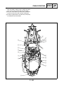
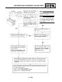
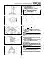
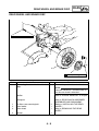
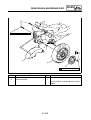
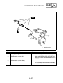
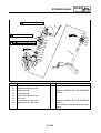
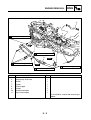
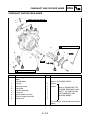
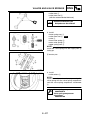
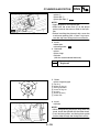
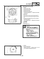
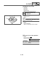
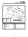
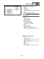
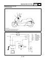
COOLING SYSTEM DIAGRAMS
SPEC
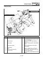
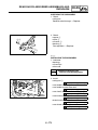
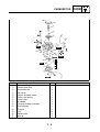
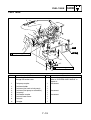
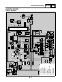
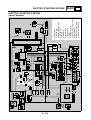
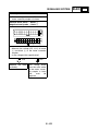
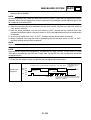
COOLING SYSTEM DIAGRAMS
1 Radiator filler hose
2 Radiator
3 Coolant reservoir hose
4 Coolant reservoir
5 Thermostat inlet hose
6 Thermostat outlet hose
7 Water pump
8 Radiator inlet/outlet pipe
9 Radiator inlet hose
0 Radiator outlet hose
A Radiator cap
B Water pump inlet hose
È 3 ~ 4 mm (0.12 ~ 0.16 in)
4
3
2
1
5
A
6
A
7
0
9
8
8
È
A
3
È
6
B
B
A
1
6
2
0
9
8
8
2 - 25
B
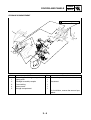
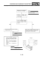
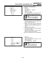
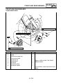
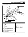
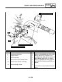
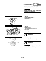
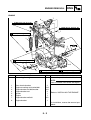
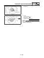
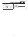
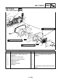
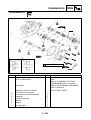
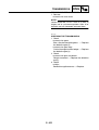
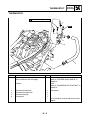
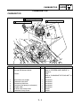
CABLE ROUTING
SPEC
EAS00035
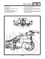
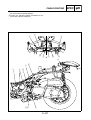
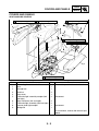
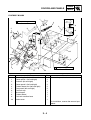
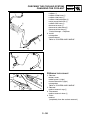
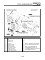
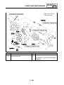
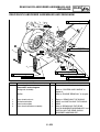
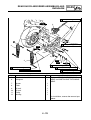
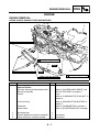
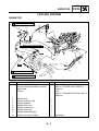
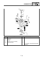
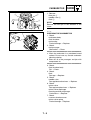
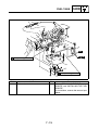
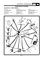
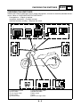
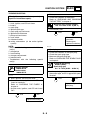
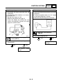
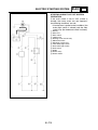
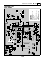
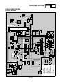
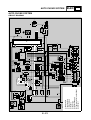
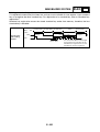
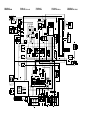
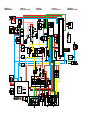
CABLE ROUTING
1 Front brake hose
2 Rear brake hose
3 Rear brake light switch lead
4 Front turn signal light coupler (left)
5 Handlebar upper cover left switches coupler
6 Handlebar upper cover right switches coupler
7 Front turn signal light coupler (right)
8 Front brake light switch lead
9 Throttle cable (decelerator cable)
1
0 Throttle cable (accelerator cable)
È Connect the air temperature sensor coupler, and
then place the air temperature sensor in the
steering head pipe.
É Connect the meter assembly coupler, and then
install the rubber cover.
Ê Apply grease to the throttle cable ends and rubber covers.
2
È É
3
0
B
A
9
4
8
7
6
5
Ë
0
C
Ê
0
9
Ê
C
9
3
2
1
8
A
B
C-C
0
9
4
7
6
5
2
1
2 - 26
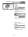
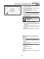
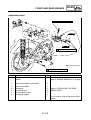
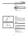
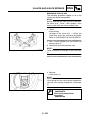
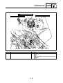
CABLE ROUTING
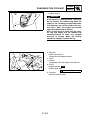
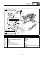
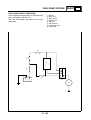
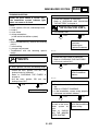
Ë After connecting the throttle cables, check the
operation of the throttle grip and make sure that
it returns to its home position easily after being
released.
1
2
È É
3
0
B
A
9
4
8
7
6
5
Ë
0
C
Ê
0
9
Ê
C
9
3
2
1
8
A
B
C-C
0
9
4
7
6
5
2
1
2 - 27
SPEC
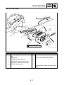
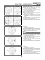
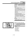
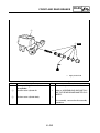
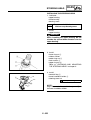
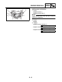
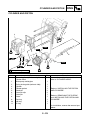
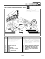
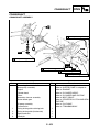
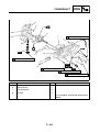
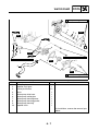
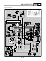
CABLE ROUTING
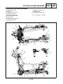
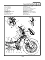
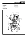
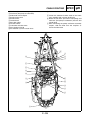
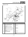
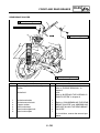
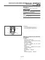
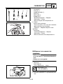
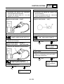
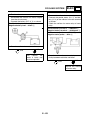
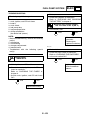
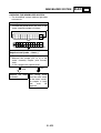
1 Wire harness
2 Rear brake hose
3 Front brake hose
4 Turn signal relay
5 Fuse box
6 Seat lock cable
7 Headlight assembly coupler
8 Starter motor lead
9 Headlight relay
0 Radiator fan motor relay
A Speed sensor lead
B Radiator filler hose
C Radiator fan motor coupler
D Fuel pump coupler
E Thermo switch (radiator fan motor)
F Thermo switch (auto choke)
G Coolant reservoir hose
H Fuel pump
I Fuel hose (fuel tank to fuel pump)
J Fuel hose (fuel pump to carburetor)
K Ground lead
L Fuel sender lead
P
O
SPEC
Q
1
3
Ö
È
1
2
×
A
A
B 3
Ø
1
B
4
5
È
A
6 7
P
O
N
8
9
0
AÉ
Õ
M
Ô
K L Ñ
Ò Ó
Ê
Ì
B
C
D
Í
Ð
J I H
G
Ï Î F
E
2 - 28
Ë
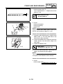
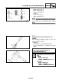
CABLE ROUTING
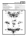
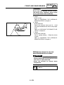
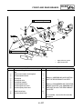
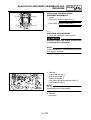
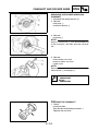
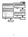
É Be sure to leave a little slack in the speed sensor
lead since the front fork moves 10 mm (0.040 in)
vertically.
Ê Fasten the front brake hose and speed sensor
lead with a holder, making sure to fasten the
front brake hose at the white tape.
Ë 15 mm (0.60 in)
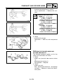
Ì To horn, and rectifier/regulator
Í Connect each thermo switch connectors (radiator fan motor) to the switch terminals of the
same color.
M Starting circuit cut-off relay
N Fuel pump relay
O Main switch coupler
P immobilizer antenna coupler
Q Throttle cables
È Fasten the wire harness with a plastic locking
tie, making sure to fasten the wire harness at the
tape.
P
O
SPEC
Q
1
3
Ö
È
1
2
×
A
A
B 3
Ø
1
B
4
5
È
A
6 7
P
O
N
8
9
0
AÉ
Õ
M
Ô
K L Ñ
Ò Ó
Ê
Ì
B
C
D
Í
Ð
J I H
G
Ï Î F
E
2 - 29
Ë
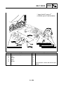
CABLE ROUTING
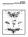
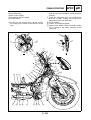
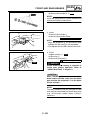
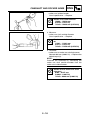
Ò Fasten the wire harness and starter motor lead
to the frame with a plastic locking tie.
Ó Fasten the rear brake pipe with a plastic locking
tie.
Ô Fasten the wire harness, relay leads (headlight
relay, radiator fan motor relay, fuel pump relay
and starting circuit cut-off relay), starter motor
lead and radiator filler hose with a plastic locking
tie.
Î Connect each thermo switch connectors (auto
choke) to the switch terminals of the same color.
Ï Fasten the coolant reservoir hose, fuel pump
lead, radiator fan motor lead and thermo switch
leads (radiator fan motor and auto choke unit) to
the frame with a plastic locking tie.
Ð Fasten the coolant reservoir hose to the frame
with a plastic locking tie.
Ñ Fasten the wire harness, rear brake pipe, starter
motor lead and sidestand switch lead with a
plastic locking tie.
P
O
SPEC
Q
1
3
Ö
È
1
2
×
A
A
B 3
Ø
1
B
4
5
È
A
6 7
P
O
N
8
9
0
AÉ
Õ
M
Ô
K L Ñ
Ò Ó
Ê
Ì
B
C
D
Í
Ð
J I H
G
Ï Î F
E
2 - 30
Ë
CABLE ROUTING
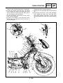
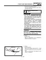
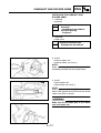
× Fasten the speed sensor lead with a plastic locking tie, making sure to install the tie around the
protective sleeve of the lead, not the lead itself,
and then connect the speed sensor coupler
Ø Cover the anti-theft alarm LED connector
(OPTION) and auxiliary DC jack fuse connector
(OPTION) with the protector.
Õ Fasten the wire harness, rear brake pipe, starter
motor lead and speed sensor lead to the frame
with a plastic locking tie, making sure to fasten
the wire harness at the tape.
Ö Fasten the main switch lead, immobilizer
antenna lead, speed sensor lead and wire harness to the frame with a plastic locking tie, making sure to position the tie between the blue tape
sections of the wire harness and to fasten the tie
around the lead protectors, not the leads themselves.
P
O
SPEC
Q
1
3
Ö
È
1
2
×
A
A
B 3
Ø
1
B
4
5
È
A
6 7
P
O
N
8
9
0
AÉ
Õ
M
Ô
K L Ñ
Ò Ó
Ê
Ì
B
C
D
Í
Ð
J I H
G
Ï Î F
E
2 - 31
Ë
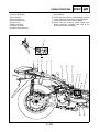
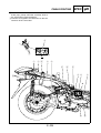
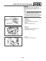
CABLE ROUTING
SPEC
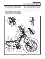
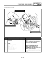
È Route the license plate light lead as shown in
the illustration.
É Fasten the wire harness, tail/brake light lead and
license plate light lead with a plastic locking tie.
Ê Fasten the wire harness with the holder
Ë Fasten the wire harness, starter motor lead,
pickup coil/stator assembly lead with to the
frame with a plastic locking tie.
1 Tail/brake light assembly coupler (right)
2 License plate light
3 Wire harness
4 Rear brake hose
5 Starter motor lead
6 Ignition coil
7 Spark plug lead
8 Coolant reservoir
9 Coolant reservoir hose
6
Í
A
1
2 É
3
4
Ê
Ë
Ì
5 6
È
7
A
9
2 - 32
8
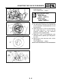
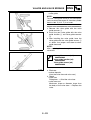
CABLE ROUTING
SPEC
Ì Fasten the wire harness, starter motor lead, rear
brake pipe, pickup coil/stator assembly lead to
the frame with a plastic locking tie.
Í Connect each ignition coil connectors to the coil
terminals of the same color.
6
Í
A
1
2 É
3
4
Ê
Ë
Ì
5 6
È
7
A
9
2 - 33
8
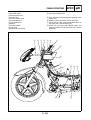
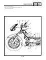
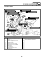
CABLE ROUTING
1 Headlight assembly coupler
2 Seat lock cable
3 Starter motor lead
4 Starter relay
5 Positive battery lead
6 Front brake hose
7 Rear brake hose
8 Battery
9 Throttle cables
0 Horn lead
A Sidestand switch lead
SPEC
B Fuel hose (fuel pump to carburetor)
C Fuel tank overflow hose
È Pass the battery lead through the opening in the
battery box.
É Route the horn lead to the rear of the frame.
Ê Fasten the seat lock cable and throttle cables to
the frame with a plastic locking tie.
Ë Fasten the seat lock cable, throttle cables and
sidestand switch lead to the frame with a plastic
locking tie.
1
2 3
4 5 6
7
È
8
9
0É
Ë A B
Ê
C Í
2 - 34
Ì
CABLE ROUTING
SPEC
Ì Fasten the sidestand switch lead to the frame
with a plastic locking tie.
Í Pass the fuel tank overflow hose through the
hole in the under cover.
1
2 3
4 5 6
7
È
8
9
0É
Ë A B
Ê
C Í
2 - 35
Ì
CABLE ROUTING
SPEC
È Fasten the seat lock cable and throttle cables
with a plastic locking tie, making sure to fasten
the throttle cables at the mark
É Pass the seat lock cable through the frame tube.
Ê Route the carburetor overflow hose to the outside of the water pump.
Ë Fasten the anti-theft alarm lead (OPTION) and
tail/brake light assembly lead (left) to the frame
with a plastic locking tie.
1 Fuel hose (fuel pump to carburetor)
2 Throttle cables
3 Seat lock cable
4 Tail/brake light assembly coupler (left)
5 Water pump
6 Carburetor overflow hose
7 Tail/brake light assembly coupler (right)
8 Anti-theft alarm lead (OPTION)
9 Anti-theft alarm (OPTION)
3
7
4
Í Ì
A
9
Ë
8
4
É
3
1
2
A
È
Ê6
5
2 - 36
CABLE ROUTING
SPEC
Ì Fasten the tail/brake light assembly lead (left) to
the frame with a plastic locking tie.
Í Fasten the anti-theft coupler (OPTION) to the
frame with a plastic locking tie.
3
7
4
Í Ì
A
9
Ë
8
4
É
3
1
2
A
È
Ê6
5
2 - 37
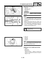
CABLE ROUTING
1 Fuse box
2 Wire harness
3 Rear brake hose
4 Throttle cables
5 Front brake hose
6 CDI unit
7 Starter relay
8 Ground coupler
9 Headlight assembly coupler
0 Rectifier/regulator
A Horn
SPEC
B Speed sensor coupler
C Main switch coupler
D Turn signal relay
E Seat lock cable
È To wire harness
É Pass the speed sensor lead through the hole in
the inner fender.
1
2 3
4
5 6
7
E
8
D
9
C
B
É
0
A
È
2 - 38
SPEC
CABLE ROUTING
1 Fuel hose (fuel tank to fuel pump)
2 Fuel hose (fuel pump to carburetor)
3 Sidestand switch coupler
4 Starter motor lead
5 Starter motor
6 Ground lead
7 Seat lock cable
8 Throttle cables
9 Carburetor overflow hose
0 Auto choke unit lead
A Air induction system vacuum hose
B Fuel sender lead
È Fasten the sidestand switch lead to the frame
cross member with a plastic locking tie.
É Route the fuel hose (fuel tank to fuel pump) and
fuel hose (fuel pump to carburetor) over the fuel
sender lead.
Ê After connecting the pickup coil/stator assembly
coupler, slide the boot over the couplers as
shown the illustration
È
1
2
B
3
Í
Ì
É
A
0
Ê
9
Ë
8
4
5
6
7
2 - 39
SPEC
CABLE ROUTING
Ë Fasten the starter motor lead and ground lead
with the holder, making sure to align the white
tape on the starter motor lead with the holder.
Ì Pass the auto choke unit lead and air induction
system vacuum hose with a plastic locking tie.
Í Fasten the grommet on the fuel hose (fuel pump
to carburetor) with the holder.
È
1
2
B
3
Í
Ì
É
A
0
Ê
9
Ë
8
4
5
6
7
2 - 40
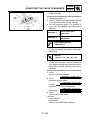
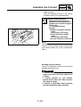
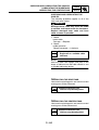
CHK
ADJ
CHAPTER 3
PERIODIC CHECKS AND ADJUSTMENTS
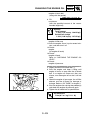
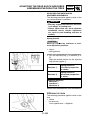
INTRODUCTION.............................................................................................. 3-1
PERIODIC MAINTENANCE AND LUBRICATION CHART ............................ 3-1
COVERS AND PANELS.................................................................................. 3-3
SEAT AND SIDE COVERS ....................................................................... 3-3
FOOTREST BOARD ................................................................................. 3-4
HANDLEBAR COVERS ............................................................................3-5
STORAGE COMPARTMENT.................................................................... 3-6
AIR FILTER CASE .......................................................................................... 3-7
ENGINE ...........................................................................................................3-8
ADJUSTING THE VALVE CLEARANCE .................................................. 3-8
ADJUSTING THE ENGINE IDLING SPEED ...........................................3-11
CHECKING THE EXHAUST GAS AT IDLE ............................................3-12
CHECKING AND ADJUSTING THE EXHAUST GAS AT IDLE .............. 3-13
ADJUSTING THE THROTTLE CABLE FREE PLAY ..............................3-15
CHECKING THE SPARK PLUG ............................................................. 3-16
CHECKING THE IGNITION TIMING.......................................................3-17
MEASURING THE COMPRESSION PRESSURE..................................3-19
CHECKING THE ENGINE OIL LEVEL....................................................3-21
CHANGING THE ENGINE OIL ...............................................................3-22
CHANGING THE FINAL TRANSMISSION OIL....................................... 3-24
REPLACING THE AIR FILTER ELEMENT ............................................. 3-25
CLEANING THE V-BELT CASE AIR FILTER ELEMENT .......................3-26
CHECKING THE FUEL AND VACUUM HOSES .................................... 3-27
CHECKING THE BREATHER HOSES ...................................................3-27
CHECKING THE EXHAUST SYSTEM....................................................3-28
CHECKING THE COOLANT LEVEL.......................................................3-29
CHECKING THE COOLING SYSTEM ....................................................3-29
CHANGING THE COOLANT................................................................... 3-30
CHK
ADJ
CHASSIS ....................................................................................................... 3-34
CHECKING THE BRAKE FLUID LEVEL................................................. 3-34
CHECKING THE FRONT AND REAR BRAKE PADS ............................ 3-35
CHECKING THE FRONT AND REAR BRAKE HOSES.......................... 3-35
BLEEDING THE HYDRAULIC BRAKE SYSTEM ................................... 3-36
CHECKING AND ADJUSTING THE STEERING HEAD ......................... 3-37
CHECKING THE FRONT FORK ............................................................. 3-39
ADJUSTING THE REAR SHOCK ABSORBER ASSEMBLIES .............. 3-40
CHECKING THE TIRES..........................................................................3-40
CHECKING THE WHEELS ..................................................................... 3-43
CHECKING AND LUBRICATING THE CABLES .................................... 3-44
LUBRICATING THE SIDESTAND........................................................... 3-44
LUBRICATING THE CENTERSTAND ....................................................3-44
ELECTRICAL SYSTEM................................................................................. 3-45
CHECKING AND CHARGING THE BATTERY....................................... 3-45
CHECKING THE FUSES ........................................................................3-51
REPLACING THE HEADLIGHT BULBS ................................................. 3-53
ADJUSTING THE HEADLIGHT BEAM ...................................................3-54
INTRODUCTION/
PERIODIC MAINTENANCE AND LUBRICATION CHART
CHK
ADJ
EAS00036
PERIODIC CHECKS AND ADJUSTMENTS
INTRODUCTION
This chapter includes all information necessary to perform recommended checks and adjustments.
If followed, these preventive maintenance procedures will ensure more reliable vehicle operation, a
longer service life and reduce the need for costly overhaul work. This information applies to vehicles
already in service as well as to new vehicles that are being prepared for sale. All service technicians
should be familiar with this entire chapter.
EAU17705
PERIODIC MAINTENANCE AND LUBRICATION CHART
NOTE:
• The annual checks must be performed every year, except if a kilometer-based maintenance
is performed instead.
• From 50000 km, repeat the maintenance intervals starting from 10000 km.
• Items marked with an asterisk should be performed by a Yamaha dealer as they require special
tools, data and technical skills.
No
1 * Fuel line
2
Spark plug
ODOMETER READING (× 1000 Km)
10
20
30
40
ANNUAL
CHECK
• Check fuel and vacuum hoses for cracks or damage.
√
√
√
√
√
• Check condition.
• Clean and regap.
√
ITEM
CHECK OR MAINTENANCE JOB
1
√
• Replace.
√
√
3 * Valves
• Check valve clearance.
• Adjust.
√
√
4
Air filter element
• Replace.
√
√
5 *
V-belt case air filter elements
• Clean.
√
6 * Front brake
• Check operation, fluid level and vehicle for fluid
leakage.
7 * Rear brake
• Check operation, fluid level and vehicle for fluid
leakage.
√
• Replace brake pads.
√
√
√
√
√
√
√
√
√
√
√
• Check for cracks or damage.
• Replace.
√
√
√
√
√
√
√
10 * Tires
•
•
•
•
√
√
√
√
11 * Wheel bearings
• Check bearing for looseness or damage.
√
√
√
√
√
√
√
14
√
Every 4 years
• Check runout and for damage.
13 * Chassis fasteners
√
Whenever worn to the limit
9 * Wheels
12 * Steering bearings
√
Whenever worn to the limit
• Replace brake pads.
8 * Brake hose
√
√
• Replace.
Check tread depth and for damage.
Replace if necessary.
Check air pressure.
Correct if necessary.
• Check bearing play and steering for roughness.
√
√
• Lubricate with lithium-soap-based grease.
• Make sure that all nuts, bolts and screws are
properly tightened.
Sidestand, center- • Check operation.
• Lubricate.
stand
3-1
√
Every 20000 km
√
√
√
√
√
√
√
√
√
√
CHK
ADJ
PERIODIC MAINTENANCE AND LUBRICATION CHART
No
ITEM
CHECK OR MAINTENANCE JOB
ODOMETER READING (× 1000 Km)
1
10
20
30
40
ANNUAL
CHECK
√
√
15 * Sidestand switch
• Check operation.
√
√
√
√
16 * Front fork
• Check operation and for oil leakage.
√
√
√
√
• Check operation and shock absorbers for oil leakage.
√
√
√
√
√
√
√
√
17 *
Shock absorber
assemblies
18 * Carburetor
19
Engine oil
√
• Adjust engine idling speed.
√
• Change.
• Check oil level and vehicle for oil leakage.
• Check coolant level and vehicle for coolant leakage.
√
• Change.
22
• Replace.
Front and rear
24 *
brake switches
• Check operation.
√
√
√
√
Every 3 years
√
Final transmission • Check vehicle for oil leakage.
oil
• Change.
23 * V-belt
√
Every 3000 km
√
20 * Engine oil strainer • Clean.
21 * Cooling system
√
When the oil change
indicator light comes on (every 3000 km)
√
√
√
√
√
Every 20000 km
√
25
Moving parts and
cables
26 *
• Check operation and free play.
Throttle grip hous• Adjust the throttle cable free play if necessary.
ing and cable
• Lubricate the throttle grip housing and cable.
27 *
Muffler and
exhaust pipe
28 *
Lights, signals and • Check operation.
• Adjust headlight beam.
switches
√
√
√
√
√
√
√
√
√
√
√
√
√
√
√
√
√
√
√
√
√
√
√
√
√
• Lubricate.
• Check the screw clamp for looseness.
√
EAU18660
NOTE:
• The air filter needs more frequent service if you are riding in unusually wet or dusty areas.
• Hydraulic brake service
• Regularly check and, if necessary, correct the brake fluid level.
• Every two years replace the internal components of the brake master cylinder and caliper, and
change the brake fluid.
• Replace the brake hoses every four years and if cracked or damaged.
3-2
COVERS AND PANELS
CHK
ADJ
EAS00038
COVERS AND PANELS
SEAT AND SIDE COVERS
8
1
3
7 Nm (0.7 m • kg, 5.1 ft • Ib)
R.
R.
R.
7 Nm (0.7 m • kg, 5.1 ft • Ib)
T.
T.
T.
23 Nm (2.3 m • kg, 17 ft • Ib)
7
9
5
4
2
6
T.
R.
23 Nm (2.3 m • kg, 17 ft • Ib)
T.
R.
3
7 Nm (0.7 m • kg, 5.1 ft • Ib)
5 7
6
(4)
T.
R.
Order
1
2
3
4
5
6
7
8
9
7 Nm (0.7 m • kg, 5.1 ft • Ib)
Job/Part
Q’ty
Remarks
Removing the seat and side covers
Remove the parts in the order listed.
Seat
1
Storage box
1
Grab bar
2
Rear cover
1
Tail/brake light assembly coupler (left
2
Disconnect.
and right)
Rear side cover (left and right)
2
Tail/brake light assembly (left and right)
2
License plate light coupler
1
Disconnect.
Mudguard
1
For installation, reverse the removal procedure.
3-3
CHK
ADJ
COVERS AND PANELS
EAS00040
FOOTREST BOARD
1
T.
R.
4
7 Nm (0.7 m • kg, 5.1 ft • Ib)
6
9
3
2
8
5
LS
1
8
7
4
3
2
5
T.
R.
7 Nm (0.7 m • kg, 5.1 ft • Ib)
10
Order
1
2
3
4
5
6
7
8
9
10
Job/Part
Removing the footrest board
Center panel 1 (left and right)
Protector (left and right)
Center panel 2 (left and right)
Footrest board mat (left and right)
Front panel (left and right)
Fuel tank cap
Seat damper
Footrest board
Fuel tank overflow hose
Under cover
Q’ty
Remarks
Remove the parts in the order listed.
2
2
2
2
2
1
1
1
1
1
For installation, reverse the removal procedure.
3-4
COVERS AND PANELS
CHK
ADJ
EAS00042
HANDLEBAR COVERS
4
4
3
7
(5)
9
5
8
6
(4)
1
2
2
Order
1
2
3
4
5
6
7
8
9
Job/Part
Removing the handlebar covers
Front turn signal light assembly
Front turn signal light coupler
Windshield
Rearview mirror (left and right)
Handlebar upper cover right switch
coupler
Handlebar upper cover left switch coupler
Handlebar upper cover (with meter
assembly)
Meter assembly coupler
Handlebar lower cover
Q’ty
Remarks
Remove the parts in the order listed.
1
2
1
2
1
Disconnect.
1
Disconnect.
Disconnect.
1
1
1
Disconnect.
For installation, reverse the removal procedure.
3-5
COVERS AND PANELS
CHK
ADJ
EAS00043
STORAGE COMPARTMENT
T.
R.
7 Nm (0.7 m • kg, 5.1 ft • Ib)
1
5
4
2
3
Order
1
2
3
4
5
Job/Part
Removing the storage compartment
Upper panel
Headlight assembly coupler
Front cowling
Battery cover
Storage compartment
Q’ty
1
1
1
1
1
Remarks
Remove the parts in the order listed.
Disconnect.
For installation, reverse the removal procedure.
3-6
CHK
ADJ
AIR FILTER CASE
AIR FILTER CASE
2
1
(6)
3
(3)
T.
R.
Order
1
2
3
9 Nm (0.9 m • kg, 6.5 ft • Ib)
Job/Part
Removing the air filter case assembly
Storage box
Cylinder head breather hose
Air induction system hose (air filter
case to air cut-off valve assembly)
Air filter case assembly
Q’ty
Remarks
Remove the parts in the order listed.
Refer to “COVERS AND PANELS”.
1
1
1
For installation, reverse the removal procedure.
3-7
ADJUSTING THE VALVE CLEARANCE
CHK
ADJ
EAS00049
ENGINE
ADJUSTING THE VALVE CLEARANCE
The following procedure applies to all of the
valves.
NOTE:
• Valve clearance adjustment should be made
on a cold engine, at room temperature.
• When the valve clearance is to be measured
or adjusted, the piston must be at top dead
center (TDC) on the compression stroke.
1. Remove:
• storage box
• footrest board
Refer to “COVERS AND PANELS”.
2. Remove:
• V-belt case air filter cover 1
3.
•
•
•
1
Remove:
spark plug
tappet covers (intake and exhaust) 1
camshaft sprocket cover 2
2
1
4. Remove:
• timing mark accessing plug 1
1
3-8
ADJUSTING THE VALVE CLEARANCE
CHK
ADJ
5. Measure:
• valve clearance
Out of specification → Adjust.
Valve clearance (cold)
Intake valve
0.08 ~ 0.12 mm
(0.0031 ~ 0.0047 in)
Exhaust valve
0.16 ~ 0.20 mm
(0.0063 ~ 0.0079 in)
▼▼▼▼▼▼▼▼▼▼▼▼▼▼▼▼▼▼▼▼▼▼▼▼▼▼▼▼▼▼▼▼
a. Turn the primary sheave nut on the left side
of the crankshaft counterclockwise to turn
the crankshaft.
b. When the piston is at TDC on the compression stroke, align the “I” mark a on the
camshaft sprocket with the stationary
pointer b on the cylinder head.
c. Align the “I” mark c on the generator rotor
with the stationary pointer d on the generator cover.
d. Measure the valve clearance with a thickness gauge 1.
Out of specification → Adjust.
b
a
▲▲▲▲▲▲▲▲▲▲▲▲▲▲▲▲▲▲▲▲▲▲▲▲▲▲▲▲▲▲▲▲
3-9
ADJUSTING THE VALVE CLEARANCE
CHK
ADJ
6. Adjust:
• valve clearance
▼▼▼▼▼▼▼▼▼▼▼▼▼▼▼▼▼▼▼▼▼▼▼▼▼▼▼▼▼▼▼▼
a. Loosen the locknut 1.
b. Insert a thickness gauge between the end
of the adjusting screw and the valve tip.
c. Turn the adjusting screw 2 in direction a
or b until the specified valve clearance is
obtained.
Direction a
Valve clearance is
increased.
Direction b
Valve clearance is
decreased.
Tappet adjusting tool
90890-01311
d. Hold the adjusting screw to prevent it from
moving and tighten the locknut to the specified torque.
T.
Locknut
14 Nm (1.4 m · kg, 1.0 ft · lb)
R.
e. Measure the valve clearance again.
f. If the valve clearance is still out of specification, repeat all of the valve clearance adjustment steps until the specified clearance is
obtained.
▲▲▲▲▲▲▲▲▲▲▲▲▲▲▲▲▲▲▲▲▲▲▲▲▲▲▲▲▲▲▲▲
7. Install:
• timing mark accessing plug
T.
R.
8 Nm (0.8 m · kg, 5.8 ft · lb)
8. Install:
• camshaft sprocket cover
T.
R.
10 Nm (1.0 m · kg, 7.2 ft · lb)
• O-rings New
• tappet covers (intake and exhaust)
T.
R.
10 Nm (1.0 m · kg, 7.2 ft · lb)
T.
18 Nm (1.8 m · kg, 13 ft · lb)
• spark plug
9. Install:
• V-belt case air filter cover
10.Install:
• footrest board
• storage box
Refer to “COVERS AND PANELS”.
R.
3 - 10
ADJUSTING THE ENGINE IDLING SPEED
CHK
ADJ
EAS00054
ADJUSTING THE ENGINE IDLING SPEED
NOTE:
Prior to adjusting the engine idling speed, the
air filter element should be cleaned, and the
engine should have adequate compression.
1. Remove:
• storage box
Refer to “COVERS AND PANELS”.
2. Start the engine and warm it up for several
minutes.
3. Connect:
• engine tachometer
(to the spark plug lead)
4. Check:
• engine idling speed
Out of specification → Adjust.
Engine idling speed
1,550 ~ 1,650 r/min
2
a
5. Adjust:
• engine idling speed
b
▼▼▼▼▼▼▼▼▼▼▼▼▼▼▼▼▼▼▼▼▼▼▼▼▼▼▼▼▼▼▼▼
1
a. Turn the pilot screw 1 in or out until it is
lightly seated.
b. Turn the pilot screw out the specified number of turns.
Pilot screw
2 turns out
c. Turn the throttle stop screw 2 in direction
a or b until the specified engine idling
speed is obtained.
Direction a
Engine idling speed is
increased.
Direction b
Engine idling speed is
decreased.
▲▲▲▲▲▲▲▲▲▲▲▲▲▲▲▲▲▲▲▲▲▲▲▲▲▲▲▲▲▲▲▲
3 - 11
ADJUSTING THE ENGINE IDLING SPEED/
CHECKING THE EXHAUST GAS AT IDLE
CHK
ADJ
6. Adjust:
• throttle cable free play
Refer to “ADJUSTING THE THROTTLE
CABLE FREE PLAY”.
Throttle cable free play
(at the flange of the throttle grip)
4.0 ~ 6.0 mm (0.16 ~ 0.24 in)
CHECKING THE EXHAUST GAS AT IDLE
Check the exhaust gas at idle when the air
induction system is operating.
1. Stand the vehicle on a level surface.
NOTE:
• Place the vehicle on a suitable stand.
• Make sure that the vehicle is upright.
2. Remove:
• storage box
Refer to “COVERS AND PANELS”.
3. Remove:
• exhaust pipe bolt 1
1
4. Connect:
• temperature probe tester 1
(to the engine oil drain bolt)
• engine tachometer
(to the spark plug lead)
• exhaust attachment 2
(to the exhaust pipe)
Exhaust attachment
90890-03134
5. Start the engine and warm it up until the
specified oil temperature is reached.
Oil temperature
65 ~ 75 °C (149 ~ 167 °F)
2
3 - 12
CHECKING THE EXHAUST GAS AT IDLE/CHECKING
AND ADJUSTING THE EXHAUST GAS AT IDLE
CHK
ADJ
6. Measure:
• engine idling speed
Out of specification → Adjust.
Refer to “ADJUSTING THE
IDLING SPEED”.
ENGINE
Engine idling speed
1,550 ~ 1,650 r/min
7. Connect:
• CO tester 1
(to the exhaust attachment)
8. Measure:
• CO density
Out of specification → Check air induction
system.
Refer to “AIR INDUCTION SYSTEM” in
chapter 7.
CO density (when air induction
system is operating)
4.0%
(Reference value)
CHECKING AND ADJUSTING THE
EXHAUST GAS AT IDLE
Check the exhaust gas at idle when the air
induction system is not operating.
1. Stand the vehicle on a level surface.
NOTE:
• Place the vehicle on a suitable stand.
• Make sure that the vehicle is upright.
• The air filter element should be cleaned, and
the engine should have adequate compression.
1
2. Remove:
• footrest board
Refer to “COVERS AND PANELS”.
3. Remove:
• exhaust pipe bolt 1
3 - 13
CHECKING AND ADJUSTING THE EXHAUST GAS AT
IDLE
CHK
ADJ
4. Connect:
• temperature probe tester 1
(to the engine oil drain bolt)
• engine tachometer
(to the spark plug lead)
• exhaust attachment 2
(to the exhaust pipe)
Exhaust attachment
90890-03134
2
5. Stop air induction system operation.
NOTE:
Crimp the hose a running from the lead valve
to the air cut-off valve to prevent the air cut-off
valve from operating.
Be sure not to damage the hose while crimping
it.
a
6. Start the engine and warm it up until the
specified oil temperature is reached.
Oil temperature
65 ~ 75 °C (149 ~ 167 °F)
7. Measure:
• engine idling speed
Out of specification → Adjust.
Refer to “ADJUSTING THE
IDLING SPEED”.
Engine idling speed
1,550 ~ 1,650 r/min
8. Connect:
• CO tester 1
(to the exhaust attachment)
3 - 14
ENGINE
CHECKING AND ADJUSTING THE EXHAUST GAS AT
IDLE/ADJUSTING THE THROTTLE CABLE FREE PLAY
CHK
ADJ
9. Measure:
• CO density
Out of specification → Adjust.
Within specification → Checking the air
induction system.
Refer to “AIR INDUCTION SYSTEM” in
chapter 7.
CO density (when air induction
system is not operating)
6.0%
10.Adjust:
• pilot screw 1
Pilot screw
2 turns out
1
If the CO density cannot be adjusted by adjusting the pilot screw, overhaul the carburetor
and check the air filter.
If there are no problems found with the carburetor or air filter, replace the muffler assembly.
11.Install:
• footrest board
Refer to “COVERS AND PANELS”.
EAS00058
a
ADJUSTING THE THROTTLE CABLE FREE
PLAY
1. Check:
• throttle cable free play a
Out of specification → Adjust.
Throttle cable free play
(at the flange of the throttle grip)
4.0 ~ 6.0 mm (0.16 ~ 0.24 in)
3 - 15
ADJUSTING THE THROTTLE CABLE FREE PLAY/
CHECKING THE SPARK PLUG
2
1
a
CHK
ADJ
2. Remove:
• front turn signal light assembly
Refer to “COVERS AND PANELS”.
▼▼▼▼▼▼▼▼▼▼▼▼▼▼▼▼▼▼▼▼▼▼▼▼▼▼▼▼▼▼▼▼
b
3
a. Slide back the rubber cover 1.
b. Loosen the locknut 2.
c. Turn the adjusting nut 3 in direction a or
b until the specified throttle cable free play
is obtained.
Direction a
Throttle cable free play
is increased.
Direction b
Throttle cable free play
is decreased.
d. Tighten the locknut.
e. Slide the rubber cover to its original position.
WARNING
After adjusting the throttle cable free play,
start the engine and turn the handlebar to
the right or left to ensure that this does not
cause the engine idling speed to change.
▲▲▲▲▲▲▲▲▲▲▲▲▲▲▲▲▲▲▲▲▲▲▲▲▲▲▲▲▲▲▲▲
3. Install:
• front turn signal light assembly
Refer to “COVERS AND PANELS”.
EAS00060
CHECKING THE SPARK PLUG
1. Remove:
• storage box
Refer to “COVERS AND PANELS”.
2. Disconnect:
• spark plug cap
3. Remove:
• spark plug
CAUTION:
Before removing the spark plug, blow away
any dirt accumulated in the spark plug well
with compressed air to prevent it from falling into the cylinder.
3 - 16
CHECKING THE SPARK PLUG/
CHECKING THE IGNITION TIMING
CHK
ADJ
4. Check:
• spark plug type
Incorrect → Change.
Spark plug type (manufacturer)
DR8EA (NGK)
5. Check:
• electrode 1
Damage/wear → Replace the spark plug.
• insulator 2
Abnormal color → Replace the spark plug.
Normal color is medium-to-light tan.
6. Clean:
• spark plug
(with a spark plug cleaner or wire brush)
7. Measure:
• spark plug gap a
(with a wire thickness gauge)
Out of specification → Regap.
Spark plug gap
0.6 ~ 0.7 mm (0.024 ~ 0.028 in)
T.
R.
8. Install:
• spark plug
18 Nm (1.8 m · kg, 13 ft · lb)
NOTE:
Before installing the spark plug, clean the
spark plug and gasket surface.
9. Connect:
• spark plug cap
10.Install:
• storage box
Refer to “COVERS AND PANELS”.
EAS00064
CHECKING THE IGNITION TIMING
NOTE:
Prior to checking the ignition timing, check the
wiring connections of the entire ignition system. Make sure that all connections are tight
and free of corrosion.
1. Stand the vehicle on a level surface.
NOTE:
Place a vehicle on the centerstand.
3 - 17
CHECKING THE IGNITION TIMING
1
CHK
ADJ
2. Remove:
• storage box
Refer to “COVERS AND PANELS”.
3. Remove:
• timing mark accessing plug 1
4. Connect:
• timing light 1
• engine tachometer
(to the spark plug lead)
Timing light
90890-03141
5. Check:
• ignition timing
▼▼▼▼▼▼▼▼▼▼▼▼▼▼▼▼▼▼▼▼▼▼▼▼▼▼▼▼▼▼▼▼
a. Start the engine, warm it up for several minutes, and then let it run at the specified
engine idling speed.
Engine idling speed
1,550 ~ 1,650 r/min
b. Check that the stationary pointer a on the
generator cover is within the firing range b
on the generator rotor.
Incorrect firing range → Check the ignition
system.
NOTE:
The ignition timing is not adjustable.
▲▲▲▲▲▲▲▲▲▲▲▲▲▲▲▲▲▲▲▲▲▲▲▲▲▲▲▲▲▲▲▲
6. Install:
• timing mark accessing plug
T.
R.
8 Nm (0.8 m · kg, 5.8 ft · lb)
7. Install:
• storage box
Refer to “COVERS AND PANELS”.
3 - 18
MEASURING THE COMPRESSION PRESSURE
CHK
ADJ
EAS00067
MEASURING THE COMPRESSION
PRESSURE
NOTE:
Insufficient compression pressure will result in
a loss of performance.
1. Remove:
• storage box
Refer to “COVERS AND PANELS”.
2. Measure:
• valve clearance
Out of specification → Adjust.
Refer to “ADJUSTING THE VALVE
CLEARANCE”.
3. Start the engine, warm it up for several minutes, and then turn it off.
4. Disconnect:
• spark plug cap
5. Remove:
• spark plug
CAUTION:
Before removing the spark plug, use compressed air to blow away any dirt accumulated in the spark plug well to prevent it
from falling into the cylinder.
1
6. Install:
• compression gauge 1
Compression gauge
90890-03081
3 - 19
MEASURING THE COMPRESSION PRESSURE
CHK
ADJ
7. Measure:
• compression pressure
Out of specification → Refer to steps (c)
and (d).
Compression pressure
(at sea level)
Minimum
1,120 kPa
(11.2 kg/cm2, 159.3 psi)
Standard
1,400 kPa
(14.0 kg/cm2, 199.1 psi)
Maximum
1,570 kPa
(15.7 kg/cm2, 223.3 psi)
▼▼▼▼▼▼▼▼▼▼▼▼▼▼▼▼▼▼▼▼▼▼▼▼▼▼▼▼▼▼▼▼
a. Set the main switch to “ON”.
b. With the throttle wide open, crank the
engine until the reading on the compression
gauge stabilizes.
WARNING
To prevent sparking, ground the spark plug
lead before cranking the engine.
c. If the compression pressure is above the
maximum specification, check the cylinder
head, valve surfaces, and piston crown for
carbon deposits.
Carbon deposits → Eliminate.
d. If the compression pressure is below the
minimum specification, pour a teaspoonful
of engine oil into the spark plug bore and
measure again.
Refer to the following table.
Compression pressure
(with oil applied into the cylinder)
Reading
Diagnosis
Higher than without oil
Piston ring(s) wear
or damage →
Repair.
Same as without
oil
Piston, valves, cylinder head gasket
or piston ring(s)
possibly defective
→ Repair.
▲▲▲▲▲▲▲▲▲▲▲▲▲▲▲▲▲▲▲▲▲▲▲▲▲▲▲▲▲▲▲▲
3 - 20
MEASURING THE COMPRESSION PRESSURE/
CHECKING THE ENGINE OIL LEVEL
CHK
ADJ
T.
8. Install:
18 Nm (1.8 m · kg, 13 ft · lb)
• spark plug
9. Connect:
• spark plug cap
10.Install:
• storage box
Refer to “COVERS AND PANELS”.
R.
EAS00070
CHECKING THE ENGINE OIL LEVEL
1. Stand the vehicle on a level surface.
NOTE:
• Place the vehicle on a centerstand.
• Make sure that the vehicle is upright.
2. Start the engine, warm it up for several minutes, and then turn it off.
3. Check:
• engine oil level
Wipe the dipstick 1 clean, insert it into the
oil filler hole (without screwing it in), and
then remove it to check the oil level.
The engine oil level should be between the
minimum level mark a and maximum level
mark b.
Below the minimum level mark → Add the
recommended engine oil to the proper level.
NOTE:
• Before checking the engine oil level, wait a
few minutes until the oil has settled.
• Do not screw the dipstick in when inspecting
the oil level.
Recommended engine oil type
SAE10W30, SAE10W40,
SAE15W40, SAE20W40, or
SAE20W50
Recommended engine oil grade
API service SG type or higher,
JASO standard MA
CAUTION:
Do not allow foreign materials to enter the
crankcase.
3 - 21
CHECKING THE ENGINE OIL LEVEL/
CHANGING THE ENGINE OIL
CHK
ADJ
4. Start the engine, warm it up for several minutes, and then turn it off.
5. Check the engine oil level again.
NOTE:
Before checking the engine oil level, wait a few
minutes until the oil has settled.
EAS00076
CHANGING THE ENGINE OIL
1. Remove:
• storage box
• footrest board
Refer to “COVERS AND PANELS”.
2. Start the engine, warm it up for several minutes, and then turn it off.
3. Place a container under the engine oil drain
bolt.
4. Remove:
• engine oil filler cap 1
• engine oil drain bolt 2
(along with the gasket)
5. Drain:
• engine oil
(completely from the crankcase)
6. If the oil strainer is also to be cleaned, perform the following procedure.
▼▼▼▼▼▼▼▼▼▼▼▼▼▼▼▼▼▼▼▼▼▼▼▼▼▼▼▼▼▼▼▼
a. Remove the oil strainer cover 1 and oil
strainer 2.
b. Install new O-ring 3.
c. Install the oil strainer cover.
T.
Oil strainer cover
32 Nm (3.2 m · kg, 23 ft · lb)
R.
▲▲▲▲▲▲▲▲▲▲▲▲▲▲▲▲▲▲▲▲▲▲▲▲▲▲▲▲▲▲▲▲
7. Check:
• engine oil drain bolt gasket
Damage → Replace.
3 - 22
CHANGING THE ENGINE OIL
CHK
ADJ
8. Install:
• engine oil drain bolt
(along with the gasket)
T.
R.
20 Nm (2.0 m · kg, 14 ft · lb)
9. Fill:
• crankcase
(with the specified amount of the recommended engine oil)
Quantity
Total amount
1.40 L (1.23 Imp qt, 1.48 US qt)
Periodic oil change
1.20 L (1.06 Imp qt, 1.27 US qt)
10.Install:
• engine oil filler cap
11.Start the engine, warm it up for several minutes, and then turn it off.
12.Check:
• engine
(for engine oil leaks)
13.Check:
• engine oil level
Refer to “CHECKING THE ENGINE OIL
LEVEL”.
14.Check:
• engine oil pressure
▼▼▼▼▼▼▼▼▼▼▼▼▼▼▼▼▼▼▼▼▼▼▼▼▼▼▼▼▼▼▼▼
1
a. Slightly loosen the oil check bolt 1.
b. Start the engine and keep it idling until
engine oil starts to seep from the oil check
bolt. If no engine oil comes out after one
minute, turn the engine off so that it will not
seize.
c. Check the engine oil passages, the oil filter
element and the oil pump for damage or
leakage. Refer to “OIL PUMP” in chapter 5.
d. Start the engine after solving the problem(s)
and check the engine oil pressure again.
e. Tighten the oil check bolt to specification.
T.
Oil check bolt
7 Nm (0.7 m · kg, 5.1 ft · lb)
R.
▲▲▲▲▲▲▲▲▲▲▲▲▲▲▲▲▲▲▲▲▲▲▲▲▲▲▲▲▲▲▲▲
3 - 23
CHANGING THE ENGINE OIL/
CHANGING THE FINAL TRANSMISSION OIL
CHK
ADJ
15.Reset:
• oil change indicator
▼▼▼▼▼▼▼▼▼▼▼▼▼▼▼▼▼▼▼▼▼▼▼▼▼▼▼▼▼▼▼▼
a. Set the main switch to “ON” while holding
the “MODE” and “SET” buttons pushed for
two to five seconds.
b. Release the buttons and the oil change indicator will go off.
NOTE:
If the engine oil is changed before the oil
change indicator comes on (i.e., before the
periodic maintenance and lubrication interval
has been reached), the oil change indicator
must be reset as soon as possible so that it
comes on for the next periodic maintenance
and lubrication interval.
▲▲▲▲▲▲▲▲▲▲▲▲▲▲▲▲▲▲▲▲▲▲▲▲▲▲▲▲▲▲▲▲
16.Install:
• footrest board
• storage box
Refer to “COVERS AND PANELS”.
1
2
1
CHANGING THE FINAL TRANSMISSION
OIL
1. Stand the vehicle on a level surface.
NOTE:
• Place the vehicle on a centerstand.
• Make sure that the vehicle is upright.
2. Start the engine, warm it up for several minutes, and then turn it off.
3. Place a container under the transmission oil
drain bolt.
4. Remove:
• final transmission oil filler cap 1
• O-ring 2
• transmission oil drain bolt 3
5. Drain:
• final transmission oil
(completely from the transmission case)
3 - 24
CHANGING THE FINAL TRANSMISSION OIL/
REPLACING THE AIR FILTER ELEMENT
CHK
ADJ
6. Install:
• final transmission oil drain bolt
T.
R.
22 Nm (2.2 m · kg, 16 ft · lb)
7. Fill:
• transmission case
(with the specified amount of the recommended transmission oil)
Recommended oil
SAE 10W30 type SE motor oil
Oil quantity
0.25 L (0.22 Imp qt, 0.26 US qt)
8.
•
•
9.
Install:
final transmission oil filler cap
O-ring
Start the engine, warm it up for several minutes, and then turn it off.
10.Check:
• transmission case
(for transmission oil leaks)
EAS00089
REPLACING THE AIR FILTER ELEMENT
NOTE:
On the bottom of the air filter case is a check
hoses. If dust or water or both collects in this
hose, remove the clamp from it, and then
remove the plug to drain the hose and clean
the air filter case.
2
1. Remove:
• air filter case cover 1
• air filter element 2
1
3 - 25
REPLACING THE AIR FILTER ELEMENT/
CLEANING THE V-BELT CASE AIR FILTER ELEMENT
CHK
ADJ
2. Check:
• air filter element
Damage → Replace.
NOTE:
• Replace the air filter element every
20,000 km of operation.
• The air filter needs more frequent service if
you are riding in unusually wet or dusty
areas.
3. Install:
• air filter element
• air filter case cover
CAUTION:
Never operate the engine without the air filter element installed. Unfiltered air will
cause rapid wear of engine parts and may
damage the engine. Operating the engine
without the air filter element will also affect
the carburetor tuning, leading to poor
engine performance and possible overheating.
EAS00091
CLEANING THE V-BELT CASE AIR FILTER
ELEMENT
1. Remove:
• center panel 1 (left)
Refer to “COVERS AND PANELS”.
2. Remove:
• V-belt case air filter cover 1
3. Clean:
• V-belt case air filter element 1
Blow the compressed air to the outer surface of the V-belt case air filter element.
3 - 26
CLEANING THE V-BELT CASE AIR FILTER ELEMENT/
CHECKING THE FUEL AND VACUUM HOSES/
CHECKING THE BREATHER HOSES
CHK
ADJ
4. Check:
• V-belt case air filter element
Damage → Replace.
CAUTION:
Since the V-belt case air filter element is a
dry type, do not let grease or water contact
it.
5.
•
6.
•
Install:
V-belt case air filter cover
Install:
center panel 1 (left)
Refer to “COVERS AND PANELS”.
EAS00096
1
3
2
CHECKING THE FUEL AND VACUUM
HOSES
1. Remove:
• storage box
Refer to “COVERS AND PANELS”.
2. Check:
• fuel hose (fuel tnak to fuel pump) 1
• fuel hose (fuel pump to carburetor) 2
• air induction system vacuum hose 3
Cracks/damage → Replace.
Loose connection → Connect properly.
3. Install:
• storage box
Refer to “COVERS AND PANELS”.
EAS00098
CHECKING THE BREATHER HOSES
1. Remove:
• storage box
Refer to “COVERS AND PANELS”.
3 - 27
CHECKING THE BREATHER HOSES/
CHECKING THE EXHAUST SYSTEM
1
CHK
ADJ
2. Check:
• cylinder head breather hose 1
• transmission case breather hose 2
Cracks/damage → Replace.
Loose connection → Connect properly.
CAUTION:
Make sure the cylinder head breather hose
and transmission case breather hose are
routed correctly.
2
3. Install:
• storage box
Refer to “COVERS AND PANELS”.
EAS00100
CHECKING THE EXHAUST SYSTEM
1. Remove:
• center panel 1 (right)
Refer to “COVERS AND PANELS”.
2. Check:
• exhaust pipe 1
• muffler 2
Cracks/damage → Replace.
• gaskets
Exhaust gas leaks → Replace.
3. Check:
• tightening torque
5
T.
R.
2
4
5
Exhaust pipe nut 3
20 Nm (2.0 m · kg, 14 ft · lb)
Muffler joint bolt 4
14 Nm (1.4 m · kg, 10 ft · lb)
Muffler mounting bolt 5
65 Nm (6.5 m · kg, 47 ft · lb)
4. Install:
• center panel 1 (right)
Refer to “COVERS AND PANELS”.
3 - 28
CHECKING THE COOLANT LEVEL/
CHECKING THE COOLING SYSTEM
CHK
ADJ
EAS00103
CHECKING THE COOLANT LEVEL
1. Stand the vehicle on a level surface.
NOTE:
• Place the vehicle on a centerstand.
• Make sure that the vehicle is upright.
2. Check:
• coolant level
The coolant level should be between the
maximum level mark a and minimum level
mark b.
Below the minimum level mark → Add the
recommended coolant to the proper level.
CAUTION:
• Adding water instead of coolant lowers
the antifreeze content of the coolant. If
water is used instead of coolant check
and, if necessary, correct the antifreeze
concentration of the coolant.
• Use only distilled water. However, if distilled water is not available, soft water
may be used.
3. Start the engine, warm it up for several minutes, and then turn it off.
4. Check:
• coolant level
NOTE:
Before checking the coolant level, wait a few
minutes until it settles.
EAS00104
CHECKING THE COOLING SYSTEM
1. Remove:
• footrest board
• storage box
Refer to “COVERS AND PANELS”.
3 - 29
CHECKING THE COOLING SYSTEM/
CHANGING THE COOLANT
CHK
ADJ
2.
•
•
•
•
•
•
•
•
•
6
1
5
3
Check:
radiator 1
radiator outlet hose 2
radiator inlet hose 3
radiator inlet/outlet pipe 4
water pump inlet hose 5
radiator filler hose 6
thermostat cover 7
thermostat outlet hose 8
thermostat inlet hose 9
Cracks/damage → Replace.
3. Install:
• storage box
• footrest board
Refer to “COVERS AND PANELS”.
4
2
9
8
7
EAS00105
1
2
CHANGING THE COOLANT
1. Remove:
• battery cover
• center panel 1 (right)
• footrest board mat (right)
• storage box
Refer to “COVERS AND PANELS”.
2. Remove:
• coolant reservoir cap 1
3. Disconnect:
• coolant reservoir hose 2
4. Drain:
• coolant
(completely from the coolant reservoir)
3 - 30
CHANGING THE COOLANT
CHK
ADJ
5. Remove:
• radiator cap 1
WARNING
A hot radiator is under pressure. Therefore,
do not remove the radiator cap when the
engine is hot. Scalding hot fluid and steam
may be blown out, which could cause serious injury. When the engine has cooled,
open the radiator cap as follows:
Place a thick rag or a towel over the radiator cap and slowly turn the radiator cap
counterclockwise to allow any residual
pressure to escape. When the hissing
sound has stopped, remove the cap.
1
1
6. Remove:
• coolant drain bolt 1
(along with the copper washer)
7. Drain:
• coolant
(completely from the engine and radiator)
8. Install:
• copper washer New
• coolant drain bolt
T.
R.
10 Nm (1.0 m · kg, 7.2 ft · lb)
9. Connect:
• coolant reservoir hose
3 - 31
CHANGING THE COOLANT
CHK
ADJ
10.Fill:
• cooling system
(with the specified amount of the recommended coolant to the specified level)
Recommended antifreeze
High-quality ethylene glycol
antifreeze containing corrosion
inhibitors for aluminum engines
Mixing ratio
1:1 (antifreeze:water)
Quantity
Radiator and engine capacity
0.70 L
(0.62 Imp qt, 0.74 US qt)
Coolant reservoir capacity
0.26 L
(0.23 Imp qt, 0.28 US qt)
Up to the maximum level mark
1
NOTE:
The specified amount of coolant is a standard
amount. Fill the cooling system with coolant
until coolant comes out of the air bleed bolt
hole 1.
Handling notes for coolant
Coolant is potentially harmful and should be
handled with special care.
WARNING
• If coolant splashes in your eyes, thoroughly wash them with water and consult
a doctor.
• If coolant splashes on your clothes,
quickly wash it away with water and then
with soap and water.
• If coolant is swallowed, induce vomiting
and get immediate medical attention.
3 - 32
CHANGING THE COOLANT
CHK
ADJ
CAUTION:
• Adding water instead of coolant lowers
the antifreeze content of the coolant. If
water is used instead of coolant check,
and if necessary, correct the antifreeze
concentration of the coolant.
• Use only distilled water. However, if distilled water is not available, soft water
may be used.
• If coolant comes into contact with painted
surfaces, immediately wash them with
water.
• Do not mix different types of antifreeze.
11.Install:
• radiator cap
a
12.Fill:
• coolant reservoir
(with the recommended coolant to the maximum level mark a)
13.Tighten:
• air bleed bolt (coolant)
14.Install:
• coolant reservoir cap
15.Start the engine, warm it up for several minutes, and then turn it off.
16.Check:
• coolant level
Refer to “CHECKING THE COOLANT
LEVEL”.
NOTE:
Before checking the coolant level, wait a few
minutes until the coolant has settled.
17.Install:
• storage box
• footrest board mat (right)
• center panel 1 (right)
• battery cover
Refer to “COVERS AND PANELS”.
3 - 33
CHECKING THE BRAKE FLUID LEVEL
CHK
ADJ
EAS01160
CHASSIS
CHECKING THE BRAKE FLUID LEVEL
1. Stand the vehicle on a level surface.
NOTE:
• Place the vehicle on the centerstand.
• Make sure the vehicle is upright.
2. Check:
• brake fluid level
Below the minimum level mark a → Add
the recommended brake fluid to the proper
level.
È
a
Recommended brake fluid
DOT 4
È Front brake
É Rear brake
É
WARNING
a
• Use only the designated brake fluid.
Other brake fluids may cause the rubber
seals to deteriorate, causing leakage and
poor brake performance.
• Refill with the same type of brake fluid
that is already in the system. Mixing
brake fluids may result in a harmful
chemical reaction, leading to poor brake
performance.
• When refilling, be careful that water does
not enter the brake fluid reservoir. Water
will significantly lower the boiling point of
the brake fluid and could cause vapor
lock.
CAUTION:
Brake fluid may damage painted surfaces
and plastic parts. Therefore, always clean
up any spilt brake fluid immediately.
NOTE:
In order to ensure a correct reading of the
brake fluid level, make sure the top of the
brake master cylinder reservoir is horizontal.
3 - 34
CHECKING THE FRONT AND REAR BRAKE PADS/
CHECKING THE FRONT AND REAR BRAKE HOSES
CHK
ADJ
EAS01220
È
a
CHECKING THE FRONT AND REAR BRAKE
PADS
The following procedure applies to all of the
brake pads.
1. Operate the brake.
2. Check:
• front brake pad
Wear limit a reached → Replace the brake
pads as a set.
É
Brake pad lining thickness limit
0.5 mm (0.02 in)
Refer to “REPLACING THE FRONT
BRAKE PADS” in chapter 4.
• rear brake pad
Wear limit a reached → Replace the brake
pads as a set.
Brake pad lining thickness limit
0.8 mm (0.03 in)
Refer to “REPLACING THE REAR BRAKE
PADS” in chapter 4.
È Front brake
É Rear brake
EAS01320
È
1
CHECKING THE FRONT AND REAR BRAKE
HOSES
The following procedure applies to all of the
brake hoses and brake hose clamps.
1. Check:
• brake hoses 1
Cracks/damage/wear → Replace.
È Front brake
É Rear brake
É
2. Check:
• brake hose clamps
Loose → Tighten the clamp bolt.
3. Hold the vehicle upright and apply the brake
several times.
4. Check:
• brake hoses
Brake fluid leakage → Replace the damaged hose.
Refer to “FRONT AND REAR BRAKES” in
chapter 4.
3 - 35
BLEEDING THE HYDRAULIC BRAKE SYSTEM
CHK
ADJ
EAS01350
BLEEDING THE HYDRAULIC BRAKE
SYSTEM
WARNING
Bleed the hydraulic brake system whenever:
• the system is disassembled.
• a brake hose is loosened, disconnected
or replaced.
• the brake fluid level is very low.
• brake operation is faulty.
NOTE:
• Be careful not to spill any brake fluid or allow
the brake master cylinder reservoir to overflow.
• When bleeding the hydraulic brake system,
make sure there is always enough brake
fluid before applying the brake. Ignoring this
precaution could allow air to enter the
hydraulic brake system, considerably lengthening the bleeding procedure.
• If bleeding is difficult, it may be necessary to
let the brake fluid settle for a few hours.
Repeat the bleeding procedure when the tiny
bubbles in the hose have disappeared.
NOTE:
1. Bleed:
• hydraulic brake system
È
▼▼▼▼▼▼▼▼▼▼▼▼▼▼▼▼▼▼▼▼▼▼▼▼▼▼▼▼▼▼▼▼
1
2
a. Fill the brake master cylinder reservoir to
the proper level with the recommended
brake fluid.
b. Install the brake master cylinder reservoir
diaphragm.
c. Connect a clear plastic hose 1 tightly to the
bleed screw 2.
È Front brake caliper
É Rear brake caliper
É
d. Place the other end of the hose into a container.
e. Slowly apply the brake several times.
f. Fully squeeze the brake lever and hold it in
position.
3 - 36
BLEEDING THE HYDRAULIC BRAKE SYSTEM/
CHECKING AND ADJUSTING THE STEERING HEAD
CHK
ADJ
g. Loosen the bleed screw.
NOTE:
Loosening the bleed screw will release the
pressure and cause the brake lever to contact
the handlebar.
h. Tighten the bleed screw and then release
the brake lever.
i. Repeat steps (e) to (h) until all of the air
bubbles have disappeared from the brake
fluid in the plastic hose.
j. Tighten the bleed screw to specification.
T.
R.
Bleed screw (front brake caliper)
6 Nm (0.6 m · kg, 4.3 ft · lb)
Bleed screw (rear brake caliper)
6 Nm (0.6 m · kg, 4.3 ft · lb)
k. Fill the brake master cylinder reservoir to
the proper level with the recommended
brake fluid.
Refer to “CHECKING THE BRAKE FLUID
LEVEL”.
WARNING
After bleeding the hydraulic brake system,
check the brake operation.
▲▲▲▲▲▲▲▲▲▲▲▲▲▲▲▲▲▲▲▲▲▲▲▲▲▲▲▲▲▲▲▲
EAS01480
CHECKING AND ADJUSTING THE
STEERING HEAD
1. Stand the vehicle on a level surface.
WARNING
Securely support the vehicle so that there
is no danger of it falling over.
NOTE:
Place the vehicle on a suitable stand so that
the front wheel is elevated.
2. Check:
• steering head
Grasp the bottom of the front fork legs and
gently rock the front fork.
Binding/looseness → Adjust the steering
head.
3 - 37
CHECKING AND ADJUSTING THE STEERING HEAD
CHK
ADJ
3. Remove:
• handlebar lower holder
Refer to “STEERING HEAD” in chapter 4.
4. Adjust:
• steering head
▼▼▼▼▼▼▼▼▼▼▼▼▼▼▼▼▼▼▼▼▼▼▼▼▼▼▼▼▼▼▼▼
a. Remove the upper ring nut 1, lock washer
2, the center ring nut 3 and the rubber
washer.
b. Loosen the lower ring nut 4 and then
tighten it to specification with the steering
nut wrench 5.
NOTE:
• Be sure to install all the ring nuts with the
broad side of the inner tapered section facing
down.
• Set the torque wrench at a right angle to the
steering nut wrench.
NOTE:
Steering nut wrench
90890-01403
T.
R.
Lower ring nut (initial tightening
torque)
38 Nm (3.8 m · kg, 27 ft · lb)
c. Loosen the lower ring nut 4 1/4 of turn and
then tighten it to specification with a steering nut wrench.
WARNING
Do not overtighten the lower ring nut.
T.
R.
Lower ring nut (final tightening
torque)
22 Nm (2.2 m · kg, 16 ft · lb)
d. Check the steering head for looseness or
binding by turning the front fork all the way
in both directions. If any binding is felt,
remove the lower bracket and check the
upper and lower bearings.
Refer to “STEERING HEAD” in chapter 4.
e. Install the rubber washer.
f. Install the center ring nut.
3 - 38
CHECKING AND ADJUSTING THE STEERING HEAD/
CHECKING THE FRONT FORK
CHK
ADJ
g. Finger tighten the center ring nut, then align
the slots of both ring nuts. If necessary, hold
the lower ring nut and tighten the center ring
nut until their slots are aligned.
NOTE:
When aligning the slots, align them by turning
the center ring nut in the tightening direction.
h. Install the lock washer 2.
NOTE:
Make sure the lock washer tabs a sit correctly
in the ring nut slots b.
i. Hold the lower and center ring nuts with a
steering nut wrench and tighten the upper
ring nut with a steering nut wrench.
Steering nut wrench
90890-01403
T.
Upper ring nut
75 Nm (7.5 m · kg, 54 ft · lb)
R.
▲▲▲▲▲▲▲▲▲▲▲▲▲▲▲▲▲▲▲▲▲▲▲▲▲▲▲▲▲▲▲▲
5.Install:
• handlebar lower holder
Refer to “STEERING HEAD” in chapter 4.
EAS01510
CHECKING THE FRONT FORK
1. Stand the vehicle on a level surface.
WARNING
Securely support the vehicle so that there
is no danger of it falling over.
2. Check:
• inner tube
Damage/scratches → Replace.
• oil seal
Oil leakage → Replace.
3. Hold the vehicle upright and apply the front
brake.
4. Check:
• front fork operation
Push down hard on the handlebar several
times and check if the front fork rebounds
smoothly.
Rough movement → Repair.
Refer to “FRONT FORK” in chapter 4.
3 - 39
ADJUSTING THE REAR SHOCK ABSORBER
ASSEMBLIES/CHECKING THE TIRES
CHK
ADJ
EAS01600
ADJUSTING THE REAR SHOCK
ABSORBER ASSEMBLIES
The following procedure applies to both of the
rear shock absorber assemblies.
WARNING
• Securely support the vehicle so that there
is no danger of it falling over.
• Always adjust both rear shock absorber
assemblies evenly. Uneven adjustment
can result in poor handling and loss of
stability.
Spring preload
CAUTION:
Never go beyond the maximum or minimum adjustment positions.
1. Adjust:
• spring preload
▼▼▼▼▼▼▼▼▼▼▼▼▼▼▼▼▼▼▼▼▼▼▼▼▼▼▼▼▼▼▼▼
a. Turn the adjusting ring 1 in direction a or
b.
Align the desired position on the adjusting
ring with the stopper 2.
Direction a
Spring preload is
increased (suspension
is harder).
Direction b
Spring preload is
decreased (suspension
is softer).
Adjusting positions
Minimum: 1
Standard: 1
Maximum: 4
▲▲▲▲▲▲▲▲▲▲▲▲▲▲▲▲▲▲▲▲▲▲▲▲▲▲▲▲▲▲▲▲
EAS01630
CHECKING THE TIRES
The following procedure applies to both of the
tires.
1. Check:
• tire pressure
Out of specification → Regulate.
3 - 40
CHECKING THE TIRES
CHK
ADJ
WARNING
• The tire pressure should only be checked
and regulated when the tire temperature
is at ambient air temperature.
• The tire pressure and the suspension
must be adjusted according to the total
weight (including cargo, rider, passenger
and accessories) and the anticipated
riding speed.
• Operation of an overloaded vehicle could
cause tire damage, an accident or an
injury.
NEVER OVERLOAD THE VEHICLE.
Basic weight
(with oil and
a full fuel
tank)
176 kg (388 lb)
Maximum
load*
180 kg (397 lb)
Cold tire
pressure
Front
Rear
Up to 90 kg
(198 lb) load*
190 kPa
(1.90 kgf/cm2,
28 psi)
220 kPa
(2.20 kgf/cm2,
32 psi)
90 kg (198 lb)
~ maximum
load*
210 kPa
(2.10 kgf/cm2,
30 psi)
250 kPa
(2.50 kgf/cm2,
36 psi)
* Total weight of rider, passenger, cargo and
accessories
WARNING
It is dangerous to ride with a worn-out tire.
When the tire tread reaches the wear limit,
replace the tire immediately.
2. Check:
• tire surfaces
Damage/wear → Replace the tire.
Minimum tire tread depth
1.6 mm (0.06 in)
1 Tire tread depth
2 Sidewall
3 Wear indicator
3 - 41
CHECKING THE TIRES
CHK
ADJ
WARNING
È
É
• Do not use a tubeless tire on a wheel
designed only for tube tires to avoid tire
failure and personal injury from sudden
deflation.
• When using tube tires, be sure to install
the correct tube.
• Always replace a new tube tire and a new
tube as a set.
• To avoid pinching the tube, make sure the
wheel rim band and tube are centered in
the wheel groove.
• Patching a punctured tube is not recommended. If it is absolutely necessary to
do so, use great care and replace the tube
as soon as possible with a good quality
replacement.
È Tire
É Wheel
Tube wheel
Tube tire only.
Tubeless wheel
Tube or tubeless tire.
• After extensive tests, the tires listed
below have been approved by Yamaha
Motor España, S.A. Ltd. for this model.
The front and rear tires should always be
by the same manufacturer and of the
same design. No guarantee concerning
handling characteristics can be given if a
tire combination other than one approved
by Yamaha is used on this vehicle.
Front tire
Manufacturer
Model
Size
MICHELIN
GOLD
STANDARD
120/70-15
M/C 56S
PIRELLI
GTS23
120/70-15
M/C 56P
Manufacturer
Model
Size
MICHELIN
GOLD
STANDARD
140/70-14
M/C 68S
PIRELLI
GTS24
140/70-14
M/C 68P
Rear tire
3 - 42
CHECKING THE TIRES/
CHECKING THE WHEELS
CHK
ADJ
WARNING
New tires have a relatively low grip on the
road surface until they have been slightly
worn. Therefore, approximately 100 km
should be traveled at normal speed before
any high-speed riding is done.
NOTE:
For tires with a rotation direction mark 1:
Install the tire with the mark pointing in the
direction of the wheel rotation.
EAS01680
CHECKING THE WHEELS
The following procedure applies to both of the
wheels.
1. Check:
• wheel
Damage/out-of-round → Replace.
WARNING
Never attempt to make any repairs to the
wheel.
NOTE:
After a tire or wheel has been changed or
replaced, always balance the wheel.
3 - 43
CHECKING AND LUBRICATING THE CABLES/
LUBRICATING THE SIDESTAND/
LUBRICATING THE CENTERSTAND
CHK
ADJ
EAS01700
CHECKING AND LUBRICATING THE
CABLES
The following procedure applies to all of the
inner and outer cables.
WARNING
Damaged outer cable may cause the cable
to corrode and interfere with its movement.
Replace damaged outer cable and inner
cable as soon as possible.
1. Check:
• outer cable
Damage → Replace.
2. Check:
• cable operation
Rough movement → Lubricate.
Recommended lubricant
Engine oil or a suitable cable
lubricant
NOTE:
Hold the cable end upright and pour a few
drops of lubricant into the cable sheath or use
a suitable lubricating device.
EAS01720
LUBRICATING THE SIDESTAND
Lubricate the pivoting point and metal-to-metal
moving parts of the sidestand.
Recommended lubricant
Lithium-soap-based grease
EAS01730
LUBRICATING THE CENTERSTAND
Lubricate the pivoting point and metal-to-metal
moving parts of the centerstand.
Recommended lubricant
Lithium-soap-based grease
3 - 44
CHECKING AND CHARGING THE BATTERY
CHK
ADJ
EAS01790
ELECTRICAL SYSTEM
CHECKING AND CHARGING THE
BATTERY
WARNING
Batteries generate explosive hydrogen gas
and contain electrolyte which is made of
poisonous and highly caustic sulfuric acid.
Therefore, always follow these preventive
measures:
• Wear protective eye gear when handling
or working near batteries.
• Charge batteries in a well-ventilated area.
• Keep batteries away from fire, sparks or
open flames (e.g., welding equipment,
lighted cigarettes).
• DO NOT SMOKE when charging or handling batteries.
• KEEP BATTERIES AND ELECTROLYTE
OUT OF REACH OF CHILDREN.
• Avoid bodily contact with electrolyte as it
can cause severe burns or permanent eye
injury.
FIRST AID IN CASE OF BODILY CONTACT:
EXTERNAL
• Skin — Wash with water.
• Eyes — Flush with water for 15 minutes
and get immediate medical attention.
INTERNAL
• Drink large quantities of water or milk followed with milk of magnesia, beaten egg
or vegetable oil. Get immediate medical
attention.
CAUTION:
• This is a sealed battery. Never remove the
sealing caps because the balance
between cells will not be maintained and
battery performance will deteriorate.
• Charging time, charging amperage and
charging voltage for an MF battery are different from those of conventional batteries. The MF battery should be charged as
explained in the charging method illustrations. If the battery is overcharged, the
electrolyte level will drop considerably.
Therefore, take special care when charging the battery.
3 - 45
CHECKING AND CHARGING THE BATTERY
CHK
ADJ
NOTE:
Since MF batteries are sealed, it is not possible to check the charge state of the battery by
measuring the specific gravity of the electrolyte. Therefore, the charge of the battery has to
be checked by measuring the voltage at the
battery terminals.
NOTE:
1. Remove:
• battery cover
Refer to “COVERS AND PANELS”.
2. Remove:
• battery bracket 1
1
2
3. Disconnect:
• battery leads
(from the battery terminals)
CAUTION:
CAUTION:
1
First, disconnect the negative battery lead
1, and then the positive battery lead 2.
4.
•
5.
•
Remove:
battery
Check:
battery charge
▼▼▼▼▼▼▼▼▼▼▼▼▼▼▼▼▼▼▼▼▼▼▼▼▼▼▼▼▼▼▼▼
a. Connect a pocket tester to the battery terminals.
Positive tester probe →
positive battery terminal
Negative tester probe →
negative battery terminal
NOTE:
• The charge state of an MF battery can be
checked by measuring its open-circuit voltage (i.e., the voltage when the positive terminal is disconnected).
• No charging is necessary when the open-circuit voltage equals or exceeds 12.8 V.
NOTE:
3 - 46
CHECKING AND CHARGING THE BATTERY
Open-circuit voltage (V)
Relationship between the open-circuit voltage and the charging time at 20 °C.
CHK
ADJ
b. Check the charge of the battery, as shown
in the charts and the following example.
Example
c. Open-circuit voltage = 12.0 V
d. Charging time = 6.5 hours
e. Charge of the battery = 20 ~ 30%
▲▲▲▲▲▲▲▲▲▲▲▲▲▲▲▲▲▲▲▲▲▲▲▲▲▲▲▲▲▲▲▲
Charging time (hours)
These values vary with the temperature, the condition of the battery plates, and the electrolyte level.
Ambient temperature 20 °C
WARNING
Open-circuit voltage (V)
Charging
6. Charge:
• battery
(Refer to the appropriate charging method
illustration.)
Do not quick charge a battery.
CAUTION:
CAUTION:
Time (minutes)
Check the open-circuit
voltage.
Open-circuit voltage (V)
Ambient temperature 20 °C
Charging condition of the battery (%)
• Never remove the MF battery sealing
caps.
• Do not use a high-rate battery charger
since it forces a high-amperage current
into the battery quickly and can cause
battery overheating and battery plate
damage.
• If it is impossible to regulate the charging
current on the battery charger, be careful
not to overcharge the battery.
• When charging a battery, be sure to
remove it from the vehicle. (If charging
has to be done with the battery mounted
on the vehicle, disconnect the negative
battery lead from the battery terminal.)
• To reduce the chance of sparks, do not
plug in the battery charger until the battery charger leads are connected to the
battery.
• Before removing the battery charger lead
clips from the battery terminals, be sure
to turn off the battery charger.
• Make sure the battery charger lead clips
are in full contact with the battery terminal and that they are not shorted. A corroded battery charger lead clip may
generate heat in the contact area and a
weak clip spring may cause sparks.
3 - 47
CHECKING AND CHARGING THE BATTERY
CHK
ADJ
• If the battery becomes hot to the touch at
any time during the charging process,
disconnect the battery charger and let the
battery cool before reconnecting it. Hot
batteries can explode!
• As shown in the following illustration, the
open-circuit voltage of an MF battery stabilizes about 30 minutes after charging
has been completed. Therefore, wait 30
minutes after charging is completed
before measuring the open-circuit voltage.
3 - 48
CHECKING AND CHARGING THE BATTERY
CHK
ADJ
Charging method using a variable-current (voltage) charger
Charger
Ammeter
Measure the open-circuit
voltage prior to charging.
NOTE:
Leave the battery unused for more
than 30 minutes before measuring
its open-circuit voltage.
Connect a charger and
ammeter to the battery and
start charging.
NOTE:
Set the charging voltage to 16 ~
17 V. (If the charging voltage is
lower charging will be insufficient,
if it is higher, the battery will be
over-charged.)
Is the amperage higher
than the standard charging
amperage written on the
battery?
NO
YES
Adjust the charging voltage to
20 ~ 25 V.
Adjust the voltage to obtain the
standard charging amperage.
YES
Monitor the amperage for 3 ~ 5
minutes. Is the standard charging amperage exceeded?
NO
Set the timer to the charging
time determined by the opencircuit voltage.
Refer to “CHECKING AND
CHARGING THE BATTERY”.
If the amperage does not
exceed the standard charging
amperage after 5 minutes,
replace the battery.
If the required charging time exceeds 5 hours, it is advisable to check
the charging amperage after 5 hours. If there is any charge in the
amperage, readjust the voltage to obtain the standard charging
amperage.
Leave the battery unused for more than 30 minutes before measuring
its open-circuit voltage.
12.8 V → Charging is complete.
12.0 ~ 12.7 V → Recharging is required.
Under 12.0 V → Replace the battery.
3 - 49
CHECKING AND CHARGING THE BATTERY
CHK
ADJ
Charging method using a constant voltage charger
Measure the open-circuit
voltage prior to charging.
NOTE:
Leave the battery unused for more
than 30 minutes before measuring
its open-circuit voltage.
Connect a charger and
ammeter to the battery and
start charging.
Is the amperage higher
than the standard charging
amperage written on the
battery?
YES
NO
Charge the battery until the charging
voltage reaches 15 V.
This type of battery charger cannot
charge an MF battery. A variable voltage charger is recommended.
NOTE:
Set the charging time to a maximum of 20 hours.
Leave the battery unused for
more than 30 minutes before
measuring its open-circuit voltage.
12.8 V → Charging is complete.
12.0 ~ 12.7 V → Recharging is
required.
Under 12.0 V → Replace the
battery.
Charger
Ammeter
Voltmeter
CAUTION:
Constant amperage chargers are not
suitable for charging MF batteries.
3 - 50
CHECKING AND CHARGING THE BATTERY/
CHECKING THE FUSES
1
7.
•
8.
•
2
CHK
ADJ
Install:
battery
Connect:
battery leads
(to the battery terminals)
CAUTION:
First, connect the positive battery lead 1,
and then the negative battery lead 2.
9. Check:
• battery terminals
Dirt → Clean with a wire brush.
Loose connection → Connect properly.
10.Lubricate:
• battery terminals
Recommended lubricant
Dielectric grease
11.Install:
• battery bracket
T.
R.
23 Nm (2.3 m · kg, 17 ft · lb)
12.Install:
• battery cover
Refer to “COVERS AND PANELS”.
EAS01810
CHECKING THE FUSES
The following procedure applies to all of the
fuses.
CAUTION:
To avoid a short circuit, always set the
main switch to “OFF” when checking or
replacing a fuse.
1. Remove:
• upper panel
Refer to “COVERS AND PANELS”.
3 - 51
CHECKING THE FUSES
CHK
ADJ
2. Check:
• fuse
▼▼▼▼▼▼▼▼▼▼▼▼▼▼▼▼▼▼▼▼▼▼▼▼▼▼▼▼▼▼▼▼
a. Connect the pocket tester to the fuse and
check the continuity.
NOTE:
Set the pocket tester selector to “Ω × 1”.
Pocket tester
90890-03112
b. If the pocket tester indicates “∞”, replace
the fuse.
▲▲▲▲▲▲▲▲▲▲▲▲▲▲▲▲▲▲▲▲▲▲▲▲▲▲▲▲▲▲▲▲
3. Replace:
• blown fuse
▼▼▼▼▼▼▼▼▼▼▼▼▼▼▼▼▼▼▼▼▼▼▼▼▼▼▼▼▼▼▼▼
a. Set the main switch to “OFF”.
b. Install a new fuse of the correct amperage
rating.
c. Set on the switches to verify if the electrical
circuit is operational.
d. If the fuse immediately blows again, check
the electrical circuit.
3 - 52
Fuses
Amperage
rating
Q’ty
Main
30 A
1
Headlight
15 A
1
Signaling system
15 A
1
Radiator fan motor
10 A
1
Ignition
5A
1
CDI unit
5A
1
Backup (meter
assembly)
5A
1
Reserve
30 A
15 A
10 A
5A
1
1
1
1
CHECKING THE FUSES/
REPLACING THE HEADLIGHT BULBS
CHK
ADJ
WARNING
Never use a fuse with an amperage rating
other than that specified. Improvising or
using a fuse with the wrong amperage rating may cause extensive damage to the
electrical system, cause the lighting and
ignition systems to malfunction and could
possibly cause a fire.
▲▲▲▲▲▲▲▲▲▲▲▲▲▲▲▲▲▲▲▲▲▲▲▲▲▲▲▲▲▲▲▲
4. Install:
• upper panel
Refer to “COVERS AND PANELS”.
EAS01830
1
1
2
2
REPLACING THE HEADLIGHT BULBS
The following procedure applies to both of the
headlight bulbs.
1. Remove:
• upper panel
Refer to “COVERS AND PANELS”.
2. Disconnect:
• headlight coupler 1
3. Remove:
• headlight bulb cover 2
4.
•
5.
•
Detach:
headlight bulb holder 1
Remove:
headlight bulb
WARNING
1
Since the headlight bulb gets extremely
hot, keep flammable products and your
hands away from the bulb until it has
cooled down.
3 - 53
REPLACING THE HEADLIGHT BULBS/
ADJUSTING THE HEADLIGHT BEAM
CHK
ADJ
6. Install:
• headlight bulb New
Secure the new headlight bulb with the
headlight bulb holder.
CAUTION:
Avoid touching the glass part of the headlight bulb to keep it free from oil, otherwise
the transparency of the glass, the life of the
bulb and the luminous flux will be
adversely affected. If the headlight bulb
gets soiled, thoroughly clean it with a cloth
moistened with alcohol or lacquer thinner.
7. Attach:
• headlight bulb holder
8. Install:
• headlight bulb cover
9. Connect:
• headlight coupler
10.Install:
• upper panel
Refer to “COVERS AND PANELS”.
EAS01860
ADJUSTING THE HEADLIGHT BEAM
1. Adjust:
• headlight beam (vertically)
▼▼▼▼▼▼▼▼▼▼▼▼▼▼▼▼▼▼▼▼▼▼▼▼▼▼▼▼▼▼▼▼
1
b
a. Turn the adjusting screw 1 in direction a
or b.
a
Direction a
Headlight beam is
raised.
Direction b
Headlight beam is lowered.
▲▲▲▲▲▲▲▲▲▲▲▲▲▲▲▲▲▲▲▲▲▲▲▲▲▲▲▲▲▲▲▲
3 - 54
CHAS
CHAPTER 4
CHASSIS
FRONT WHEEL AND BRAKE DISC............................................................... 4-1
REMOVING THE FRONT WHEEL............................................................ 4-3
CHECKING THE FRONT WHEEL ............................................................ 4-3
CHECKING THE BRAKE DISC.................................................................4-5
ADJUSTING THE FRONT WHEEL STATIC BALANCE ........................... 4-6
INSTALLING THE FRONT WHEEL .......................................................... 4-8
REAR WHEEL AND BRAKE DISC.................................................................4-9
REMOVING THE REAR WHEEL ............................................................ 4-11
CHECKING THE REAR WHEEL............................................................. 4-11
ADJUSTING THE REAR WHEEL STATIC BALANCE............................ 4-12
INSTALLING THE REAR WHEEL........................................................... 4-12
FRONT AND REAR BRAKES....................................................................... 4-13
FRONT BRAKE PADS ............................................................................4-13
REAR BRAKE PADS............................................................................... 4-14
REPLACING THE FRONT BRAKE PADS .............................................. 4-15
REPLACING THE REAR BRAKE PADS................................................. 4-17
FRONT BRAKE MASTER CYLINDER....................................................4-19
REAR BRAKE MASTER CYLINDER ......................................................4-22
DISASSEMBLING THE FRONT BRAKE MASTER CYLINDER ............. 4-25
DISASSEMBLING THE REAR BRAKE MASTER CYLINDER................ 4-25
CHECKING THE FRONT AND REAR BRAKE MASTER
CYLINDERS ........................................................................................... 4-26
ASSEMBLING AND INSTALLING THE FRONT BRAKE MASTER
CYLINDER ............................................................................................. 4-27
ASSEMBLING AND INSTALLING THE REAR BRAKE MASTER
CYLINDER ............................................................................................. 4-29
FRONT BRAKE CALIPER....................................................................... 4-33
REAR BRAKE CALIPER .........................................................................4-36
DISASSEMBLING THE FRONT BRAKE CALIPER ................................4-38
DISASSEMBLING THE REAR BRAKE CALIPER ..................................4-39
CHECKING THE FRONT AND REAR BRAKE CALIPERS ....................4-40
ASSEMBLING AND INSTALLING THE FRONT BRAKE CALIPER ....... 4-41
ASSEMBLING AND INSTALLING THE REAR BRAKE CALIPER..........4-43
FRONT FORK................................................................................................4-47
REMOVING THE FRONT FORK LEGS.................................................. 4-50
DISASSEMBLING THE FRONT FORK LEGS ........................................ 4-50
CHECKING THE FRONT FORK LEGS .................................................. 4-52
ASSEMBLING THE FRONT FORK LEGS .............................................. 4-53
INSTALLING THE FRONT FORK LEGS ................................................ 4-58
HANDLEBAR ................................................................................................4-59
REMOVING THE HANDLEBAR..............................................................4-61
CHECKING THE HANDLEBAR ..............................................................4-61
CHAS
INSTALLING THE HANDLEBAR ............................................................ 4-61
STEERING HEAD.......................................................................................... 4-64
LOWER BRACKET ................................................................................. 4-64
REMOVING THE LOWER BRACKET.....................................................4-66
CHECKING THE STEERING HEAD .......................................................4-67
INSTALLING THE STEERING HEAD .....................................................4-68
REAR SHOCK ABSORBER ASSEMBLIES AND SWINGARM................... 4-69
REMOVING THE REAR SHOCK ABSORBER ASSEMBLIES ............... 4-71
CHECKING THE REAR SHOCK ABSORBER ASSEMBLIES................ 4-71
INSTALLING THE REAR SHOCK ABSORBER ASSEMBLIES.............. 4-72
REMOVING THE SWINGARM................................................................4-72
CHECKING THE SWINGARM ................................................................4-73
INSTALLING THE SWINGARM ..............................................................4-73
FRONT WHEEL AND BRAKE DISC
CHAS
EAS05130
CHASSIS
FRONT WHEEL AND BRAKE DISC
T.
R.
9 Nm (0.9 m • kg, 6.5 ft • Ib)
1
LS
4
(5)
2
LT
6
5
R.
59 Nm (5.9 m • kg, 43 ft • Ib)
T.
R.
12 Nm (1.2 m • kg, 8.7 ft • Ib)
Order
1
2
3
4
5
6
T.
3
Job/Part
Removing the front wheel and brake
disc
Front wheel axle pinch bolt
Front wheel axle
Front wheel
Speed sensor
Spacer
Front brake disc
Q’ty
2
1
1
1
1
1
Remarks
Remove the parts in the order listed.
Loosen.
Refer to “REMOVING THE
FRONT WHEEL” and
“INSTALLING THE FRONT
WHEEL”.
For installation, reverse the removal procedure.
4-1
FRONT WHEEL AND BRAKE DISC
CHAS
EAS05130
Order
1
2
3
Job/Part
Disassembling the front wheel
Oil seal
Bearing
Collar
Q’ty
Remarks
Remove the parts in the order listed.
1
2
1
For assembly, reverse the disassembly
procedure.
4-2
FRONT WHEEL AND BRAKE DISC
CHAS
EAS05200
REMOVING THE FRONT WHEEL
1. Stand the vehicle on a level surface.
WARNING
Securely support the vehicle so that there
is no danger of it falling over.
2. Elevate:
• front wheel
NOTE:
Place the vehicle on a suitable stand so that
the front wheel is elevated.
3.
•
•
•
Remove:
front wheel
speed sensor
spacer
NOTE:
Do not squeeze the front brake lever when
removing the front wheel.
NOTE:
EAS05250
CHECKING THE FRONT WHEEL
1. Check:
• wheel axle
Roll the wheel axle on a flat surface.
Bends → Replace.
WARNING
Do not attempt to straighten a bent wheel
axle.
2. Check:
• tire
• front wheel
Damage/wear → Replace.
Refer to “CHECKING THE TIRES” and
“CHECKING THE WHEELS” in chapter 3.
4-3
FRONT WHEEL AND BRAKE DISC
CHAS
3. Measure:
• radial wheel runout 1
• lateral wheel runout 2
Over the specified limits → Replace.
Radial wheel runout limit
1.0 mm (0.04 in)
Lateral wheel runout limit
0.5 mm (0.02 in)
4. Check:
• wheel bearings
Front wheel turns roughly or is loose →
Replace the wheel bearings.
• oil seal
Damage/wear → Replace.
5. Replace:
• wheel bearings New
• oil seal New
▼▼▼▼▼▼▼▼▼▼▼▼▼▼▼▼▼▼▼▼▼▼▼▼▼▼▼▼▼▼▼▼
a. Clean the outside of the front wheel hub.
b. Remove the oil seal 1 with a flat-head
screwdriver.
NOTE:
To prevent damaging the wheel, place a rag 2
between the screwdriver and the wheel surface.
c. Remove the wheel bearings 3 with a general bearing puller.
d. Install the new wheel bearings and oil seal
in the reverse order of disassembly.
CAUTION:
Do not contact the wheel bearing inner race
4 or ball 5. Contact should be made only
with the outer race 6.
NOTE:
Use a socket 7 that matches the diameter of
the wheel bearing outer race and oil seal.
▲▲▲▲▲▲▲▲▲▲▲▲▲▲▲▲▲▲▲▲▲▲▲▲▲▲▲▲▲▲▲▲
4-4
FRONT WHEEL AND BRAKE DISC
CHAS
EAS05280
CHECKING THE BRAKE DISC
1. Check:
• brake disc
Damage/galling → Replace.
2. Measure:
• brake disc deflection
Out of specification → Correct the brake
disc deflection or replace the brake disc.
Brake disc deflection limit (maximum)
Front: 0.10 mm (0.0039 in)
Rear: 0.15 mm (0.0059 in)
▼▼▼▼▼▼▼▼▼▼▼▼▼▼▼▼▼▼▼▼▼▼▼▼▼▼▼▼▼▼▼▼
a. Place the vehicle on a suitable stand so that
the front wheel is elevated.
b. Before measuring the front brake disc
deflection, turn the handlebar to the left or
right to ensure that the front wheel is stationary.
c. Remove the brake caliper.
d. Hold the dial gauge at a right angle against
the brake disc surface.
e. Measure the deflection 1.5 mm (0.059 in)
below the edge of the brake disc.
▲▲▲▲▲▲▲▲▲▲▲▲▲▲▲▲▲▲▲▲▲▲▲▲▲▲▲▲▲▲▲▲
3. Measure:
• brake disc thickness
Measure the brake disc thickness at a few
different locations.
Out of specification → Replace.
Brake disc thickness limit (minimum)
Front: 4.5 mm (0.18 in)
Rear: 4.5 mm (0.18 in)
4-5
FRONT WHEEL AND BRAKE DISC
CHAS
4. Adjust:
• brake disc deflection
▼▼▼▼▼▼▼▼▼▼▼▼▼▼▼▼▼▼▼▼▼▼▼▼▼▼▼▼▼▼▼▼
a. Remove the brake disc.
b. Rotate the brake disc by one bolt hole.
c. Install the brake disc.
NOTE:
• Install the brake disc with the recessed bolt
holes facing outward. (For front brake disc)
• Tighten the brake disc bolts in stages and in
a crisscross pattern.
T.
R.
Brake disc bolt
12 Nm (1.2 m · kg, 8.7 ft · lb)
LOCTITE®
d. Measure the brake disc deflection.
e. If out of specification, repeat the adjustment
steps until the brake disc deflection is within
specification.
f. If the brake disc deflection cannot be
brought within specification, replace the
brake disc.
▲▲▲▲▲▲▲▲▲▲▲▲▲▲▲▲▲▲▲▲▲▲▲▲▲▲▲▲▲▲▲▲
EAS05480
ADJUSTING THE FRONT WHEEL STATIC
BALANCE
NOTE:
• After replacing the tire, wheel or both, the
front wheel static balance should be
adjusted.
• Adjust the front wheel static balance with the
brake disc installed.
1.
•
2.
•
Remove:
balancing weight(s)
Find:
front wheel’s heavy spot
NOTE:
Place the front wheel on a suitable balancing
stand.
4-6
FRONT WHEEL AND BRAKE DISC
CHAS
▼▼▼▼▼▼▼▼▼▼▼▼▼▼▼▼▼▼▼▼▼▼▼▼▼▼▼▼▼▼▼▼
a. Spin the front wheel.
b. When the front wheel stops, put an “X1”
mark at the bottom of the wheel.
c. Turn the front wheel 90° so that the “X1”
mark is positioned as shown.
d. Release the front wheel.
e. When the wheel stops, put an “X2” mark at
the bottom of the wheel.
f. Repeat steps (d) through (f) several times
until all the marks come to rest at the same
spot.
g. The spot where all the marks come to rest
is the front wheel’s heavy spot “X”.
▲▲▲▲▲▲▲▲▲▲▲▲▲▲▲▲▲▲▲▲▲▲▲▲▲▲▲▲▲▲▲▲
3. Adjust:
• front wheel static balance
▼▼▼▼▼▼▼▼▼▼▼▼▼▼▼▼▼▼▼▼▼▼▼▼▼▼▼▼▼▼▼▼
a. Install a balancing weight 1 onto the rim
exactly opposite the heavy spot “X”.
NOTE:
Start with the lightest weight.
b. Turn the front wheel 90° so that the heavy
spot is positioned as shown.
c. If the heavy spot does not stay in that position, install a heavier weight.
d. Repeat steps (b) and (c) until the front
wheel is balanced.
▲▲▲▲▲▲▲▲▲▲▲▲▲▲▲▲▲▲▲▲▲▲▲▲▲▲▲▲▲▲▲▲
4. Check:
• front wheel static balance
▼▼▼▼▼▼▼▼▼▼▼▼▼▼▼▼▼▼▼▼▼▼▼▼▼▼▼▼▼▼▼▼
a. Turn the front wheel and make sure it stays
at each position shown.
b. If the front wheel does not remain stationary
at all of the positions, rebalance it.
▲▲▲▲▲▲▲▲▲▲▲▲▲▲▲▲▲▲▲▲▲▲▲▲▲▲▲▲▲▲▲▲
4-7
FRONT WHEEL AND BRAKE DISC
CHAS
EAS05420
INSTALLING THE FRONT WHEEL
1. Lubricate:
• oil seal lips
• speed sensor
Recommended lubricant
Lithium-soap-based grease
2.
•
•
•
a
Install:
spacer
speed sensor
front wheel
NOTE:
• Make sure that the speed sensor and the
wheel hub are installed with the projection a
of the wheel hub inserted in a slot b of the
speed sensor.
• When installing the speed sensor, make sure
that the projection on the wheel hub does not
damage the lip of the speed sensor oil seal.
• Make sure that the slot c in the speed sensor fits over the stopper d on the outer tube.
b
c
d
3. Tighten:
• front wheel axle
T.
R.
59 Nm (5.9 m · kg, 43 ft · lb)
• front wheel axle pinch bolts
T.
R.
9 Nm (0.9 m · kg, 6.5 ft · lb)
WARNING
Make sure the brake hose is routed properly.
CAUTION:
Before tightening the wheel axle, push
down hard on the handlebar several times
and check if the front fork rebounds
smoothly.
4-8
CHAS
REAR WHEEL AND BRAKE DISC
EAS05520
REAR WHEEL AND BRAKE DISC
1
T.
R.
9 Nm (0.9 m • kg, 6.5 ft • Ib)
LS
5
4
LT
(4)
2
3
6
T.
R.
Order
Job/Part
Removing the rear wheel and brake
disc
Q’ty
23 Nm (2.3 m • kg, 17 ft • Ib)
Remarks
Remove the parts in the order listed.
NOTE:
Place the vehicle on a suitable stand so
that the rear wheel is elevated.
Muffler
Swingarm
1
2
3
Air filter case mounting bolt
Rear fender
Rear wheel
2
1
1
4
Spacer
1
4-9
Refer to “ENGINE REMOVAL” in chapter
5.
Refer to “REAR SHOCK ABSORBER
ASSEMBLIES AND SWINGARM”.
Refer to “INSTALLING THE REAR
WHEEL”.
Refer to “REMOVING THE REAR
WHEEL”.
CHAS
REAR WHEEL AND BRAKE DISC
1
T.
R.
9 Nm (0.9 m • kg, 6.5 ft • Ib)
LS
5
4
LT
(4)
2
3
6
T.
R.
Order
5
6
Job/Part
Washer
Rear brake disc
Q’ty
1
1
23 Nm (2.3 m • kg, 17 ft • Ib)
Remarks
For installation, reverse the removal procedure.
4 - 10
REAR WHEEL AND BRAKE DISC
CHAS
REMOVING THE REAR WHEEL
1. Stand the vehicle on a level surface.
WARNING
Securely support the vehicle so that there
is no danger of it falling over.
NOTE:
Place the vehicle on a centerstand so that the
rear wheel is elevated.
2.
•
•
•
Remove:
brake caliper
rear wheel axle nut
swingarm
Refer to “REAR SHOCK ABSORBER
ASSEMBLIES AND SWINGARM”.
NOTE:
Do not squeeze the rear brake lever when
removing the rear brake caliper.
3. Remove:
• rear wheel
EAS05650
CHECKING THE REAR WHEEL
1. Check:
• tire
• rear wheel
Damage/wear → Replace.
Refer to “CHECKING THE TIRES” and
“CHECKING THE WHEELS” in chapter 3.
2. Measure:
• radial wheel runout
• lateral wheel runout
Refer to “CHECKING THE FRONT
WHEEL”.
4 - 11
REAR WHEEL AND BRAKE DISC
CHAS
EAS05750
ADJUSTING THE REAR WHEEL STATIC
BALANCE
NOTE:
• After replacing the tire, wheel or both, the
rear wheel static balance should be adjusted.
• Adjust the rear wheel static balance with the
brake disc installed.
1. Adjust:
• rear wheel static balance
Refer to “ADJUSTING THE
WHEEL STATIC BALANCE”.
FRONT
INSTALLING THE REAR WHEEL
1. Install:
• rear fender
• air filter case mounting bolts
T.
R.
9 Nm (0.9 m · kg, 6.5 ft · lb)
NOTE:
Place the rear fender between the air filter
case and the crankcase, and then install the
air filter case mounting bolts.
4 - 12
FRONT AND REAR BRAKES
CHAS
EAS05770
FRONT AND REAR BRAKES
FRONT BRAKE PADS
1
T.
R.
23 Nm (2.3 m • kg, 17 ft • Ib)
T.
R.
6 Nm (0.6 m • kg, 4.3 ft • Ib)
2
New 4
8
5
6
7
6
3
T.
R.
Order
1
2
3
4
5
6
7
8
12 Nm (1.2 m • kg, 8.7 ft • Ib)
Job/Part
Removing the front brake pads
Holder
Front brake caliper bolt
Front brake caliper
Brake pad clip
Brake pad pin
Brake pad
Brake pad spring
Brake pad support
Q’ty
1
2
1
1
1
2
1
1
Remarks
Remove the parts in the order listed.
Refer to “REPLACING THE FRONT
BRAKE PADS”.
For installation, reverse the removal procedure.
4 - 13
CHAS
FRONT AND REAR BRAKES
EAS05780
REAR BRAKE PADS
T.
R.
4
6 Nm (0.6 m • kg, 4.3 ft • Ib)
3
5
6
2
6
1
4
T.
R.
27 Nm (2.7 m • kg, 19 ft • Ib)
* Apply silicone grease.
T.
R.
40 Nm (4.0 m • kg, 29 ft • Ib)
Order
Job/Part
Removing the rear brake pads
Muffler
Q’ty
1
2
3
4
5
6
Rear brake caliper retaining bolt
Rear brake caliper
Brake pad
Brake pad shim
Brake caliper bracket
Brake pad support
2
1
2
4
1
2
Remarks
Remove the parts in the order listed.
Refer to “ENGINE REMOVAL” in chapter
5.
Refer to “REPLACING THE REAR
BRAKE PADS”.
For installation, reverse the removal procedure.
4 - 14
FRONT AND REAR BRAKES
CHAS
EAS00579
CAUTION:
_
Disc brake components rarely require disassembly.
Therefore, always follow these preventive
measures:
• Never disassemble brake components
unless absolutely necessary.
• If any connection on the hydraulic brake
system is disconnected, the entire brake
system must be disassembled, drained,
cleaned, properly filled, and bled after
reassembly.
• Never use solvents on internal brake
components.
• Use only clean or new brake fluid for
cleaning brake components.
• Brake fluid may damage painted surfaces
and plastic parts. Therefore, always clean
up any spilt brake fluid immediately.
• Avoid brake fluid coming into contact
with the eyes as it can cause serious
injury.
FIRST AID FOR BRAKE FLUID ENTERING
THE EYES:
• Flush with water for 15 minutes and get
immediate medical attention.
EAS05820
1
REPLACING THE FRONT BRAKE PADS
NOTE:
When replacing the brake pads, it is not necessary to disconnect the brake hose or disassemble the brake caliper.
2
5
3
4
1.
•
•
•
•
•
•
•
4 - 15
Remove:
brake caliper bolts 1
brake caliper 2
brake pad clip 3
brake pad pin 4
brake pads 5
brake pad spring
brake pad support
FRONT AND REAR BRAKES
CHAS
2. Measure:
• brake pad wear limit a
Out of specifications → Replace the brake
pads as a set.
a
1
Brake pad wear limit
0.5 mm (0.02 in)
3.
•
•
•
2
Install:
brake pad support
brake pad spring
brake pads
NOTE:
Always install new brake pads, brake pad
spring, and brake pad support as a set.
▼▼▼▼▼▼▼▼▼▼▼▼▼▼▼▼▼▼▼▼▼▼▼▼▼▼▼▼▼▼▼▼
a. Connect a clear plastic hose 1 tightly to the
bleed screw 2. Put the other end of the
hose into an open container.
b. Loosen the bleed screw and push the brake
caliper pistons into the brake caliper with
your finger.
c. Tighten the bleed screw.
a
T.
Bleed screw
6 Nm (0.6 m · kg, 4.3 ft · lb)
R.
d. Install the new brake pads, new brake pad
spring, and new brake pad support.
NOTE:
The arrow mark a on the brake pad spring
must point in the direction of disc rotation.
▲▲▲▲▲▲▲▲▲▲▲▲▲▲▲▲▲▲▲▲▲▲▲▲▲▲▲▲▲▲▲▲
4. Install:
• brake caliper bolts
T.
R.
4 - 16
23 Nm (2.3 m · kg, 17 ft · lb)
FRONT AND REAR BRAKES
a
CHAS
5. Check:
• brake fluid level
Below the minimum level mark a → Add
the recommended brake fluid to the proper
level.
Refer to “CHECKING THE BRAKE FLUID
LEVEL” in chapter 3.
6. Check:
• brake lever operation
Soft or spongy feeling → Bleed the brake
system.
Refer to “BLEEDING THE HYDRAULIC
BRAKE SYSTEM” in chapter 3.
EAS05830
REPLACING THE REAR BRAKE PADS
NOTE:
When replacing the brake pads, it is not necessary to disconnect the brake hose or disassemble the brake caliper.
1.
•
•
•
Remove:
brake caliper retaining bolts 1
brake caliper 2
brake pads
(along with the brake pad shims)
• brake caliper bracket 3
• brake pad supports
2. Measure:
• brake pad wear limit a
Out of specification → Replace the brake
pads as a set.
Brake pad wear limit
0.8 mm (0.03 in)
4 - 17
FRONT AND REAR BRAKES
CHAS
3. Install:
• brake pad supports
• brake pads
(along with the brake pad shims)
2
1
NOTE:
Always install new brake pads, brake pad
shims, and a brake pad supports as a set.
▼▼▼▼▼▼▼▼▼▼▼▼▼▼▼▼▼▼▼▼▼▼▼▼▼▼▼▼▼▼▼▼
a. Connect a clear plastic hose 1 tightly to the
bleed screw 2. Put the other end of the
hose into an open container.
b. Loosen the bleed screw and push the brake
caliper pistons into the brake caliper with
your finger.
c. Tighten the bleed screw.
T.
Bleed screw
6 Nm (0.6 m · kg, 4.3 ft · lb)
R.
d. Install new brake pad shims onto each new
brake pads.
e. Install new brake pad supports and new
brake pads.
▲▲▲▲▲▲▲▲▲▲▲▲▲▲▲▲▲▲▲▲▲▲▲▲▲▲▲▲▲▲▲▲
4. Install:
• brake caliper bolts
T.
R.
40 Nm (4.0 m · kg, 29 ft · lb)
• brake caliper retaining bolts
T.
R.
a
27 Nm (2.7 m · kg, 19 ft · lb)
5. Check:
• brake fluid level
Below the minimum level mark a → Add
the recommended brake fluid to the proper
level.
Refer to “CHECKING THE BRAKE FLUID
LEVEL” in chapter 3.
6. Check:
• brake lever operation
Soft or spongy feeling → Bleed the brake
system.
Refer to “BLEEDING THE HYDRAULIC
BRAKE SYSTEM” in chapter 3.
4 - 18
CHAS
FRONT AND REAR BRAKES
EAS05840
FRONT BRAKE MASTER CYLINDER
1
T.
R.
7 Nm (0.7 m • kg, 5.1 ft • Ib)
2
3
10
8
9
11
T.
R.
10 Nm (1.0 m • kg, 7.2 ft • Ib)
7
6 New
5
T.
R.
Order
Job/Part
Removing the front brake master
cylinder
Handlebar lower cover
4
23 Nm (2.3 m • kg, 17 ft • Ib)
Q’ty
Refer to “COVERS AND PANELS” in
chapter 3.
Drain.
Refer to “BLEEDING THE HYDRAULIC
BRAKE SYSTEM” in chapter 3.
Brake fluid
1
2
3
4
Brake master cylinder reservoir cap
Brake master cylinder reservoir diaphragm holder
Brake master cylinder reservoir diaphragm
Front brake light switch connector
Remarks
Remove the parts in the order listed.
1
1
1
2
4 - 19
Disconnect.
CHAS
FRONT AND REAR BRAKES
1
T.
R.
7 Nm (0.7 m • kg, 5.1 ft • Ib)
2
3
10
8
9
11
T.
R.
10 Nm (1.0 m • kg, 7.2 ft • Ib)
7
6 New
5
T.
R.
Order
5
6
7
Job/Part
Brake hose union bolt
Copper washer
Front brake hose
4
23 Nm (2.3 m • kg, 17 ft • Ib)
Q’ty
1
2
1
8
9
Front brake master cylinder holder
Brake master cylinder assembly
1
1
10
11
Front brake lever
Front brake light switch
1
1
Remarks
Refer to “DISASSEMBLING THE
FRONT BRAKE MASTER CYLINDER”
and “ASSEMBLING AND INSTALLING
THE FRONT BRAKE MASTER CYLINDER”.
Refer to “ASSEMBLING AND INSTALLING THE FRONT BRAKE MASTER
CYLINDER”.
For installation, reverse the removal procedure.
4 - 20
FRONT AND REAR BRAKES
CHAS
1 New
2
** Apply brake fluid
Order
1
Job/Part
Disassembling the front brake master cylinder
Brake master cylinder kit
2
Brake master cylinder body
Q’ty
1
Remarks
Remove the parts in the order listed.
Refer to “ASSEMBLING AND INSTALLING THE FRONT BRAKE MASTER CYLINDER”.
1
For assembly, reverse the disassembly
procedure.
4 - 21
CHAS
FRONT AND REAR BRAKES
EAS05860
REAR BRAKE MASTER CYLINDER
T.
R.
7 Nm (0.7 m • kg, 5.1 ft • Ib)
1
2
9
3
10
5
New 7
11
8
New 7
4
6
T.
R.
T.
R.
Order
1
2
3
4
10 Nm (1.0 m • kg, 7.2 ft • Ib)
23 Nm (2.3 m • kg, 17 ft • Ib)
Job/Part
Q’ty
Remarks
Removing the rear brake master cylRemove the parts in the order listed.
inder
Handlebar lower cover
Refer to “COVERS AND PANELS” in
chapter 3.
Brake fluid
Drain.
Refer to “BLEEDING THE HYDRAULIC
BRAKE SYSTEM” in chapter 3.
Brake master cylinder reservoir cap
1
Brake master cylinder reservoir dia1
phragm holder
Brake master cylinder reservoir dia1
phragm
Rear brake lever
1
4 - 22
CHAS
FRONT AND REAR BRAKES
T.
R.
7 Nm (0.7 m • kg, 5.1 ft • Ib)
1
2
9
3
10
5
New 7
11
8
New 7
4
6
T.
R.
10 Nm (1.0 m • kg, 7.2 ft • Ib)
T.
R.
23 Nm (2.3 m • kg, 17 ft • Ib)
Order
5
6
7
8
Job/Part
Rear brake light switch connector
Brake hose union bolt
Copper washer
Rear brake hose
9
10
Rear brake master cylinder holder
Brake master cylinder assembly
11
Rear brake light switch
Q’ty
Remarks
2
Disconnect.
1
Refer to “DISASSEMBLING THE REAR
BRAKE MASTER CYLINDER” and
2
“ASSEMBLING AND INSTALLING THE
1
REAR BRAKE MASTER CYLINDER”.
1
Refer to “ASSEMBLING AND INSTALLING THE REAR BRAKE MASTER CYL1
INDER”.
1
For installation, reverse the removal procedure.
4 - 23
FRONT AND REAR BRAKES
CHAS
EAS05870
2
1 New
** Apply brake fluid
Order
1
Job/Part
Disassembling the rear brake master cylinder
Brake master cylinder kit
2
Brake master cylinder body
Q’ty
1
Remarks
Remove the parts in the order listed.
Refer to “ASSEMBLING AND INSTALLING THE REAR BRAKE MASTER CYLINDER”.
1
For assembly, reverse the disassembly
procedure.
4 - 24
FRONT AND REAR BRAKES
CHAS
EAS05880
DISASSEMBLING THE FRONT BRAKE
MASTER CYLINDER
NOTE:
Before disassembling the front brake master
cylinder, drain the brake fluid from the entire
brake system.
3
1.
•
•
•
Remove:
brake hose union bolt 1
copper washers 2
brake hose 3
NOTE:
To collect any remaining brake fluid, place a
container under the master cylinder and the
end of the brake hose.
2
1
EAS05890
DISASSEMBLING THE REAR BRAKE
MASTER CYLINDER
NOTE:
Before disassembling the rear brake master
cylinder, drain the brake fluid from the entire
brake system.
1.
•
•
•
2
3
1
Remove:
brake hose union bolt 1
copper washers 2
brake hose 3
NOTE:
To collect any remaining brake fluid, place a
container under the master cylinder and the
end of the brake hose.
4 - 25
FRONT AND REAR BRAKES
È
EAS05920
É
1
CHAS
1
CHECKING THE FRONT AND REAR BRAKE
MASTER CYLINDERS
The following procedure applies to both of the
brake master cylinders.
1. Check:
• brake master cylinder 1
Damage/scratches/wear → Replace.
• brake fluid delivery passages
(brake master cylinder body)
Obstruction → Blow out with compressed
air.
È Front
É Rear
1
2. Check:
• brake master cylinder kit 1
Damage/scratches/wear → Replace.
3. Check:
• brake master cylinder reservoir cap 1
Cracks/damage → Replace.
• brake master cylinder reservoir diaphragm
holder 2
• brake master cylinder diaphragm 3
Damage/wear → Replace.
4. Check:
• brake hoses
Cracks/damage/wear → Replace.
4 - 26
FRONT AND REAR BRAKES
CHAS
EAS06000
ASSEMBLING AND INSTALLING THE
FRONT BRAKE MASTER CYLINDER
WARNING
• Before installation, all internal brake components should be cleaned and lubricated
with clean or new brake fluid.
• Never use solvents on internal brake
components.
Recommended brake fluid
DOT 4
1. Install:
• brake master cylinder kit 1 New
NOTE:
Install the spring with its smaller diameter end
towards the circlip and dust boot.
1
2. Install:
• brake master cylinder 1
• brake master cylinder holder
T.
R.
b
a
7 Nm (0.7 m · kg, 5.1 ft · lb)
NOTE:
• Align the projection a on the brake master
cylinder with the hole b in the handlebar.
• First tighten the front bolt, then the rear bolt.
4 - 27
FRONT AND REAR BRAKES
2
a
3.
•
•
•
CHAS
Install:
copper washers 1 New
brake hose 2
brake hose union bolt 3
T.
R.
23 Nm (2.3 m · kg, 17 ft · lb)
WARNING
New 1
3
Proper brake hose routing is essential to
insure safe vehicle operation. Refer to
“CABLE ROUTING” in chapter 2.
CAUTION:
When installing the brake hose onto the
brake master cylinder, make sure the brake
pipe touches the projection a on the brake
master cylinder.
NOTE:
Turn the handlebar to the left and right to make
sure the brake hose does not touch other parts
(e.g., wire harness, cables, leads). Correct if
necessary.
4. Fill:
• brake master cylinder reservoir
(with the specified amount of the recommended brake fluid)
Recommended brake fluid
DOT 4
WARNING
• Use only the designated brake fluid.
Other brake fluids may cause the rubber
seals to deteriorate, causing leakage and
poor brake performance.
• Refill with the same type of brake fluid
that is already in the system. Mixing
brake fluids may result in a harmful
chemical reaction, leading to poor brake
performance.
• When refilling, be careful that water does
not enter the brake master cylinder reservoir. Water will significantly lower the
boiling point of the brake fluid and could
cause vapor lock.
4 - 28
FRONT AND REAR BRAKES
CHAS
CAUTION:
Brake fluid may damage painted surfaces
and plastic parts. Therefore, always clean
up any spilt brake fluid immediately.
a
5. Bleed:
• brake system
Refer to “BLEEDING THE HYDRAULIC
BRAKE SYSTEM” in chapter 3.
6. Check:
• brake fluid level
Below the minimum level mark a → Add
the recommended brake fluid to the proper
level.
Refer to “CHECKING THE BRAKE FLUID
LEVEL” in chapter 3.
7. Check:
• brake lever operation
Soft or spongy feeling → Bleed the brake
system.
Refer to “BLEEDING THE HYDRAULIC
BRAKE SYSTEM” in chapter 3.
EAS06001
ASSEMBLING AND INSTALLING THE
REAR BRAKE MASTER CYLINDER
WARNING
• Before installation, all internal brake components should be cleaned and lubricated
with clean or new brake fluid.
• Never use solvents on internal brake
components.
Recommended brake fluid
DOT 4
4 - 29
FRONT AND REAR BRAKES
CHAS
1. Install:
• brake master cylinder kit 1 New
NOTE:
Install the spring with its smaller diameter end
towards the circlip and dust boot.
2. Install:
• brake master cylinder 1
• brake master cylinder holder
1
T.
R.
b
a
NOTE:
• Align the projection a on the brake master
cylinder with the hole b in the handlebar.
• First tighten the front bolt, then the rear bolt.
3.
•
•
•
a
Install:
copper washers 1 New
brake hose 2
brake hose union bolt 3
T.
R.
1 New
2
3
7 Nm (0.7 m · kg, 5.1 ft · lb)
23 Nm (2.3 m · kg, 17 ft · lb)
WARNING
Proper brake hose routing is essential to
insure safe vehicle operation. Refer to
“CABLE ROUTING” in chapter 2.
CAUTION:
When installing the brake hose onto the
brake master cylinder, make sure the brake
pipe touches the projection a on the brake
master cylinder.
NOTE:
Turn the handlebar to the left and right to make
sure the brake hose does not touch other parts
(e.g., wire harness, cables, leads). Correct if
necessary.
4 - 30
FRONT AND REAR BRAKES
CHAS
4. Fill:
• brake master cylinder reservoir
(with the specified amount of the recommended brake fluid)
Recommended brake fluid
DOT 4
WARNING
• Use only the designated brake fluid.
Other brake fluids may cause the rubber
seals to deteriorate, causing leakage and
poor brake performance.
• Refill with the same type of brake fluid
that is already in the system. Mixing
brake fluids may result in a harmful
chemical reaction, leading to poor brake
performance.
• When refilling, be careful that water does
not enter the brake master cylinder reservoir. Water will significantly lower the
boiling point of the brake fluid and could
cause vapor lock.
CAUTION:
Brake fluid may damage painted surfaces
and plastic parts. Therefore, always clean
up any spilt brake fluid immediately.
5. Bleed:
• brake system
Refer to “BLEEDING THE HYDRAULIC
BRAKE SYSTEM” in chapter 3.
a
6. Check:
• brake fluid level
Below the minimum level mark a → Add
the recommended brake fluid to the proper
level.
Refer to “CHECKING THE BRAKE FLUID
LEVEL” in chapter 3.
4 - 31
FRONT AND REAR BRAKES
CHAS
7. Check:
• brake lever operation
Soft or spongy feeling → Bleed the brake
system.
Refer to “BLEEDING THE HYDRAULIC
BRAKE SYSTEM” in chapter 3.
4 - 32
FRONT AND REAR BRAKES
CHAS
EAS06120
FRONT BRAKE CALIPER
T.
R.
4
6 Nm (0.6 m • kg, 4.3 ft • Ib)
6
1
2
3 New
5
T.
R.
23 Nm (2.3 m • kg, 17 ft • Ib)
T.
R.
Order
1
2
3
4
5
6
Job/Part
Removing the front brake caliper
Brake fluid
Holder
Brake hose union bolt
Copper washer
Front brake hose
Front brake caliper bolt
Front brake caliper
Q’ty
1
1
2
1
2
1
23 Nm (2.3 m • kg, 17 ft • Ib)
Remarks
Remove the parts in the order listed.
Drain.
Refer to “BLEEDING THE HYDRAULIC
BRAKE SYSTEM” in chapter 3.
Refer to “DISASSEMBLING THE
FRONT BRAKE CALIPER” and
“ASSEMBLING AND INSTALLING THE
FRONT BRAKE CALIPER”.
For installation, reverse the removal procedure.
4 - 33
FRONT AND REAR BRAKES
*
CHAS
Apply silicone grease
** Apply brake fluid
Order
1
2
3
4
5
6
7
8
9
0
Job/Part
Disassembling the front brake caliper
Brake pad clip
Brake pad pin
Brake pad
Brake pad support
Brake pad spring
Brake caliper bracket
Brake caliper housing
Brake caliper piston
Brake caliper dust seal
Brake caliper piston seal
Q’ty
1
1
2
1
1
1
1
2
2
2
4 - 34
Remarks
Remove the parts in the order listed.
Refer to “ASSEMBLING AND INSTALLING THE FRONT BRAKE CALIPER”.
Refer to “DISASSEMBLING THE
FRONT BRAKE CALIPER” and
“ASSEMBLING AND INSTALLING THE
FRONT BRAKE CALIPER”.
FRONT AND REAR BRAKES
*
CHAS
Apply silicone grease
** Apply brake fluid
Order
A
B
Job/Part
Bleed screw/cap
Brake caliper body
Q’ty
1/1
1
Remarks
For assembly, reverse the disassembly
procedure.
4 - 35
FRONT AND REAR BRAKES
CHAS
EAS06160
REAR BRAKE CALIPER
T.
R.
23 Nm (2.3 m • kg, 17 ft • Ib)
T.
R.
6 Nm (0.6 m • kg, 4.3 ft • Ib)
4
1
2
6
T.
3 New
R.
7 Nm (0.7 m • kg, 5.1 ft • Ib)
5
T.
R.
Order
Job/Part
Removing the rear brake caliper
Muffler
Q’ty
Brake fluid
1
2
3
4
5
6
Brake hose holder
Brake hose union bolt
Copper washer
Rear brake hose
Rear brake caliper bolt
Rear brake caliper
1
1
2
1
3
1
40 Nm (4.0 m • kg, 29 ft • Ib)
Remarks
Remove the parts in the order listed.
Refer to “ENGINE REMOVAL” in
chapter5.
Drain.
Refer to “BLEEDING THE HYDRAULIC
BRAKE SYSTEM” in chapter 3.
Refer to “DISASSEMBLING THE REAR
BRAKE CALIPER” and “ASSEMBLING
AND INSTALLING THE REAR BRAKE
CALIPER”.
For installation, reverse the removal procedure.
4 - 36
FRONT AND REAR BRAKES
CHAS
2
T.
R.
6 Nm (0.6 m • kg, 4.3 ft • Ib)
9
0
6
7 New
8 New
1
1
5
T.
4
R.
27 Nm (2.7 m • kg, 19 ft • Ib)
3
5
4
*
Apply silicone grease
** Apply brake fluid
Order
Q’ty
1
2
3
4
5
6
7
8
Job/Part
Disassembling the rear brake caliper
Rear brake caliper retaining bolt
Brake caliper bracket
Brake pad
Brake pad shim
Brake pad support
Brake caliper piston
Brake caliper dust seal
Brake caliper piston seal
9
0
Bleed screw/cap
Brake caliper body
1/1
1
2
1
2
4
2
2
2
2
Remarks
Remove the parts in the order listed.
Refer to “ASSEMBLING AND INSTALLING THE REAR BRAKE CALIPER”.
Refer to “DISASSEMBLING THE REAR
BRAKE CALIPER” and “ASSEMBLING
AND INSTALLING THE REAR BRAKE
CALIPER”.
For assembly, reverse the disassembly
procedure.
4 - 37
FRONT AND REAR BRAKES
CHAS
EAS06190
4
3
DISASSEMBLING THE FRONT BRAKE
CALIPER
NOTE:
Before disassembling the brake caliper, drain
the brake fluid from the entire brake system.
1
2
5
1.
•
•
•
•
•
Remove:
brake hose union bolt 1
copper washers 2
brake hose 3
brake caliper bolts 4
brake caliper 5
NOTE:
Put the end of the brake hose into a container
and pump out the brake fluid carefully.
1
2. Remove:
• brake caliper bracket 1
• brake caliper housing 2
2
3. Remove:
• brake caliper pistons 1
• brake caliper dust seals and piston seals 2
2
▼▼▼▼▼▼▼▼▼▼▼▼▼▼▼▼▼▼▼▼▼▼▼▼▼▼▼▼▼▼▼▼
a. Blow compressed air into the brake hose
joint opening a to force out the pistons
from the brake caliper.
1
2
WARNING
a
• Cover the brake caliper pistons with a
rag. Be careful not to get injured when the
pistons are expelled from the brake caliper.
• Never try to pry out the brake caliper pistons.
b. Remove the brake caliper dust seals and
piston seals.
▲▲▲▲▲▲▲▲▲▲▲▲▲▲▲▲▲▲▲▲▲▲▲▲▲▲▲▲▲▲▲▲
4 - 38
FRONT AND REAR BRAKES
CHAS
EAS00627
DISASSEMBLING THE REAR BRAKE
CALIPER
NOTE:
Before disassembling the brake caliper, drain
the brake fluid from the entire brake system.
1.
•
•
•
•
•
Remove:
brake hose union bolt 1
copper washers 2
brake hose 3
brake caliper retaining bolts
brake caliper
NOTE:
Put the end of the brake hose into a container
and pump out the brake fluid carefully.
2. Remove:
• brake caliper pistons 1
• brake caliper dust seals and piston seals 2
▼▼▼▼▼▼▼▼▼▼▼▼▼▼▼▼▼▼▼▼▼▼▼▼▼▼▼▼▼▼▼▼
a. Blow compressed air into the brake hose
joint opening a to force out the pistons
from the brake caliper.
WARNING
a
• Cover the brake caliper pistons with a
rag. Be careful not to get injured when the
pistons are expelled from the brake caliper.
• Never try to pry out the brake caliper pistons.
b. Remove the brake caliper dust seals and
piston seals.
▲▲▲▲▲▲▲▲▲▲▲▲▲▲▲▲▲▲▲▲▲▲▲▲▲▲▲▲▲▲▲▲
4 - 39
FRONT AND REAR BRAKES
CHAS
EAS06330
CHECKING THE FRONT AND REAR BRAKE
CALIPERS
Recommended brake component
replacement schedule
È
2
1
É
Brake pads
If necessary
Dust seals, Piston
seals
Every two years
Brake hose
Every four years
Brake fluid
Every two years
and whenever the
brake is disassembled
3
1. Check:
• brake caliper pistons 1
Rust/scratches/wear → Replace the brake
caliper pistons.
• brake caliper cylinders 2
Scratches/wear → Replace the brake caliper assembly.
• brake caliper body 3
Cracks/damage → Replace the brake caliper assembly.
• brake fluid delivery passages (brake caliper
body)
Obstruction → Blow out with compressed
air.
WARNING
Whenever a brake caliper is disassembled,
replace the brake caliper piston seals.
È Front
É Rear
2. Check:
• brake caliper bracket
Cracks/damage → Replace.
4 - 40
FRONT AND REAR BRAKES
CHAS
EAS06350
ASSEMBLING AND INSTALLING THE
FRONT BRAKE CALIPER
WARNING
• Before installation, all internal brake components should be cleaned and lubricated
with clean or new brake fluid.
• Never use solvents on internal brake
components as they will cause the piston
seals to swell and distort.
• Whenever a brake caliper is disassembled, replace the brake caliper dust seals
and piston seals.
New 1
Recommended brake fluid
DOT 4
2
1 New
1. Install:
• brake caliper dust seals
seals 1 New
• brake calliper pistons 2
2. Install:
• brake caliper housing
and
piston
T.
R.
45 Nm (4.5 m · kg, 32 ft · lb)
• brake caliper bracket
3
1
4
3. Install:
• brake caliper 1
(temporarily)
• copper washers 2 New
• brake hose 3
• brake hose union bolt 4
T.
R.
New 2
23 Nm (2.3 m · kg, 17 ft · lb)
WARNING
Proper brake hose routing is essential to
insure safe vehicle operation. Refer to
“CABLE ROUTING” in chapter 2.
45˚ ± 2˚
CAUTION:
While holding the brake hose, tighten the
union bolt within the range shown in the
illustration.
4 - 41
FRONT AND REAR BRAKES
CHAS
4.
•
5.
•
•
•
Remove:
brake caliper
Install:
brake pad support
brake pad spring
brake pads
Refer to “REPLACING
BRAKE PADS”.
6. Install:
• brake caliper
• brake caliper bolts
THE
FRONT
T.
R.
23 Nm (2.3 m · kg, 17 ft · lb)
7. Fill:
• brake master cylinder reservoir
(with the specified amount of the recommended brake fluid)
Recommended brake fluid
DOT 4
WARNING
• Use only the designated brake fluid.
Other brake fluids may cause the rubber
seals to deteriorate, causing leakage and
poor brake performance.
• Refill with the same type of brake fluid
that is already in the system. Mixing
brake fluids may result in a harmful
chemical reaction, leading to poor brake
performance.
• When refilling, be careful that water does
not enter the brake master cylinder reservoir. Water will significantly lower the
boiling point of the brake fluid and could
cause vapor lock.
CAUTION:
Brake fluid may damage painted surfaces
and plastic parts. Therefore, always clean
up any spilt brake fluid immediately.
8. Bleed:
• brake system
Refer to “BLEEDING THE HYDRAULIC
BRAKE SYSTEM” in chapter 3.
4 - 42
FRONT AND REAR BRAKES
a
CHAS
9. Check:
• brake fluid level
Below the minimum level mark a → Add
the recommended brake fluid to the proper
level.
Refer to “CHECKING THE BRAKE FLUID
LEVEL” in chapter 3.
10.Check:
• brake lever operation
Soft or spongy feeling → Bleed the brake
system.
Refer to “BLEEDING THE HYDRAULIC
BRAKE SYSTEM” in chapter 3.
EAS06351
ASSEMBLING AND INSTALLING THE
REAR BRAKE CALIPER
WARNING
• Before installation, all internal brake components should be cleaned and lubricated
with clean or new brake fluid.
• Never use solvents on internal brake
components.
• Whenever a brake caliper is disassembled, replace the brake caliper dust seals
and piston seals.
Recommended brake fluid
DOT 4
1. Install:
• brake caliper dust seals
seals 1 New
• brake calliper pistons 2
2. Install:
• brake pad supports
• brake caliper bracket
T.
R.
4 - 43
and
piston
40 Nm (4.0 m · kg, 29 ft · lb)
FRONT AND REAR BRAKES
CHAS
3. Install:
• brake caliper 1
(temporarily)
• copper washers 2 New
• brake hose 3
• brake hose union bolt 4
T.
R.
23 Nm (2.3 m · kg, 17 ft · lb)
WARNING
Proper brake hose routing is essential to
insure safe vehicle operation. Refer to
“CABLE ROUTING” in chapter 2.
CAUTION:
When installing the brake hose onto the
brake caliper, make sure the brake pipe
touches the projection a on the brake caliper.
4.
•
5.
•
•
Remove:
brake caliper
Install:
brake pad shims
brake pads
Refer to “REPLACING THE REAR BRAKE
PADS”.
6. Install:
• brake caliper
• brake caliper retaining bolts
T.
R.
4 - 44
27 Nm (2.7 m · kg, 19 ft · lb)
FRONT AND REAR BRAKES
CHAS
7. Fill:
• brake master cylinder reservoir
(with the specified amount of the recommended brake fluid)
Recommended brake fluid
DOT 4
WARNING
• Use only the designated brake fluid.
Other brake fluids may cause the rubber
seals to deteriorate, causing leakage and
poor brake performance.
• Refill with the same type of brake fluid
that is already in the system. Mixing
brake fluids may result in a harmful
chemical reaction, leading to poor brake
performance.
• When refilling, be careful that water does
not enter the brake master cylinder reservoir. Water will significantly lower the
boiling point of the brake fluid and could
cause vapor lock.
CAUTION:
Brake fluid may damage painted surfaces
and plastic parts. Therefore, always clean
up any spilt brake fluid immediately.
8. Bleed:
• brake system
Refer to “BLEEDING THE HYDRAULIC
BRAKE SYSTEM” in chapter 3.
a
9. Check:
• brake fluid level
Below the minimum level mark a → Add
the recommended brake fluid to the proper
level.
Refer to “CHECKING THE BRAKE FLUID
LEVEL” in chapter 3.
4 - 45
FRONT AND REAR BRAKES
CHAS
10.Check:
• brake lever operation
Soft or spongy feeling → Bleed the brake
system.
Refer to “BLEEDING THE HYDRAULIC
BRAKE SYSTEM” in chapter 3.
4 - 46
FRONT FORK
CHAS
EAS06460
FRONT FORK
New 3
T.
R.
22 Nm (2.2 m • kg, 16 ft • Ib)
4
T.
R.
23 Nm (2.3 m • kg, 17 ft • Ib)
1
2
5
Order
Job/Part
Removing the front fork legs
Q’ty
Front cowling
Front wheel
1
Front brake caliper
1
2
3
4
5
Front fender
Clip
Lower bracket pinch bolt
Front fork leg
1
1
2
1
4 - 47
Remarks
Remove the parts in the order listed.
The following procedure applies to both
of the front fork legs.
Refer to “COVERS AND PANELS” in
chapter 3.
Refer to “FRONT WHEEL AND BRAKE
DISC”.
Refer to “REMOVING THE FRONT
FORK LEGS”.
Refer to “REMOVING THE FRONT
FORK LEGS” and “INSTALLING THE
FRONT FORK LEGS”.
For installation, reverse the removal procedure.
FRONT FORK
Order
1
2
3
4
5
6
7
8
9
0
A
Job/Part
Disassembling the front fork legs
Rubber cap
Circlip
Front fork cap
O-ring
Fork spring
Dust seal
Oil seal clip
Damper rod bolt
Copper washer
Damper rod
Rebound spring
Q’ty
1
1
1
1
1
1
1
1
1
1
1
4 - 48
CHAS
Remarks
Remove the parts in the order listed.
The following procedure applies to both
of the front fork legs.
Refer to “DISASSEMBLING THE
FRONT FORK LEGS” and “ASSEMBLING THE FRONT FORK LEGS”.
FRONT FORK
Order
B
C
D
E
F
G
H
Job/Part
Inner tube
Inner tube bushing
Oil flow stopper
Oil seal
Washer
Outer tube bushing
Outer tube
Q’ty
1
1
1
1
1
1
1
CHAS
Remarks
Refer to “DISASSEMBLING THE
FRONT FORK LEGS” and “ASSEMBLING THE FRONT FORK LEGS”.
For assembly, reverse the disassembly
procedure.
4 - 49
FRONT FORK
CHAS
EAS06490
REMOVING THE FRONT FORK LEGS
The following procedure applies to both of the
front fork legs.
1. Stand the vehicle on a level surface.
WARNING
Securely support the vehicle so that there
is no danger of it falling over.
NOTE:
Place the vehicle on a suitable stand so that
the front wheel is elevated.
2.
•
3.
•
1
2
Remove:
clip 1
Loosen:
lower bracket pinch bolts 2
WARNING
Support the front fork leg while loosening
the lower bracket pinch bolts.
4. Remove:
• front fork leg
EAS06520
1
1
2
DISASSEMBLING THE FRONT FORK LEGS
The following procedure applies to both of the
front fork legs.
1. Remove:
• rubber cap
• circlip 1
• front fork cap 2
• O-ring
• fork spring
NOTE:
Push the front fork cap in the direction of the
arrow shown in the illustration to remove the
circlip.
4 - 50
FRONT FORK
CHAS
2. Drain:
• fork oil
NOTE:
Stroke the inner tube several times while
draining the fork oil.
1
3. Remove:
• dust seal 1
• oil seal clip 2
(with a flat-head screwdriver)
CAUTION:
2
Do not scratch the inner tube.
4.
•
•
•
Remove:
damper rod bolt 1
damper rod
rebound spring
NOTE:
Hold the damper rod with the damper rod
holder 2 and T-handle 3, then loosen the
damper rod bolt.
Damper rod holder
90890-01294
T-handle
90890-01326
4 - 51
FRONT FORK
CHAS
5. Remove:
• inner tube
▼▼▼▼▼▼▼▼▼▼▼▼▼▼▼▼▼▼▼▼▼▼▼▼▼▼▼▼▼▼▼▼
a. Hold the front fork leg horizontally.
b. Securely clamp the brake caliper bracket in
a vise with soft jaws.
c. Separate the inner tube from the outer tube
by pulling the inner tube forcefully but carefully.
CAUTION:
• Excessive force will damage the oil seal
and bushing. A damaged oil seal or bushing must be replaced.
• Avoid bottoming the inner tube into the
outer tube during the above procedure,
as the oil flow stopper will be damaged.
▲▲▲▲▲▲▲▲▲▲▲▲▲▲▲▲▲▲▲▲▲▲▲▲▲▲▲▲▲▲▲▲
EAS06560
CHECKING THE FRONT FORK LEGS
The following procedure applies to both of the
front fork legs.
1. Check:
• inner tube 1
• outer tube 2
Bends/damage/scratches → Replace.
WARNING
Do not attempt to straighten a bent inner
tube as this may dangerously weaken it.
2. Measure:
• spring free length a
Out of specification → Replace.
Spring free length
308.0 mm (12.126 in)
Limit
301.87 mm (11.885 in)
4 - 52
FRONT FORK
1
2
CHAS
3. Check:
• damper rod 1
Damage/wear → Replace.
Obstruction → Blow out all of the oil passages with compressed air.
• oil flow stopper 2
Damage → Replace.
CAUTION:
When disassembling and assembling the
front fork leg, do not allow any foreign
material to enter the front fork.
EAS06590
ASSEMBLING THE FRONT FORK LEGS
The following procedure applies to both of the
front fork legs.
WARNING
• Make sure the oil levels in both front fork
legs are equal.
• Uneven oil levels can result in poor handling and a loss of stability.
NOTE:
• When assembling the front fork leg, be sure
to replace the following parts:
- outer tube bushing
- inner tube bushing
- oil seal
- dust seal
- O-ring
- clip
• Before assembling the front fork leg, make
sure all of the components are clean.
4 - 53
FRONT FORK
2 1
CHAS
1. Install:
• damper rod 1
• rebound spring 2
3
CAUTION:
Allow the damper rod to slide slowly down
the inner tube 3 until it protrudes from the
bottom of the inner tube. Be careful not to
damage the inner tube.
2. Lubricate:
• inner tube’s outer surface
Recommended lubricant
Fork oil 15 W or equivalent
2
4
3. Install:
• inner tube bushing 1 New
• inner tube 2
(into outer tube 3)
• oil flow stopper 4
1 New
3
4. Install:
• copper washer 1 New
• damper rod bolt 2
New 1
2
4 - 54
FRONT FORK
CHAS
5. Tighten:
• damper rod bolt 1
T.
Damper rod bolt
28 Nm (2.8 m · kg, 20 ft · lb)
R.
NOTE:
Hold the damper rod with the damper rod
holder 2 and T-handle 3, then tighten the
damper rod bolt.
Damper rod holder
90890-01294
T-handle
90890-01326
6. Install:
• outer tube bushing 1 New
• washer 2
(with the fork seal driver weight 3 and fork
seal driver attachment 4)
Fork seal driver weight
90890-01367
Fork seal driver attachment (ø36)
90890-01370
4 - 55
FRONT FORK
CHAS
7. Install:
• oil seal 1 New
(with the fork seal driver weight 2 and fork
seal driver attachment 3)
CAUTION:
Make sure the numbered side of the oil seal
faces up.
Fork seal driver weight
90890-01367
Fork seal driver attachment (ø36)
90890-01370
NOTE:
• Before installing the oil seal, lubricate its lips
with lithium-soap-based grease.
• Lubricate the outer surface of the inner tube
with fork oil.
• Before installing the oil seal, cover the top of
the front fork leg with a plastic bag to protect
the oil seal during installation.
8. Install:
• oil seal clip 1
NOTE:
Adjust the oil seal clip so that it fits into the
outer tube’s groove.
9. Install:
• dust seal 1 New
(with the fork seal driver weight 2)
Fork seal driver weight
90890-01367
4 - 56
FRONT FORK
CHAS
10.Fill:
• front fork leg
(with the specified amount of the recommended fork oil)
Quantity (each front fork leg)
195.0 cm3
(6.86 Imp oz, 6.59 US oz)
Recommended oil
Fork oil 15 W or equivalent
Front fork leg oil level a (from
the top of the inner tube, with the
inner tube fully compressed and
without the fork spring)
105.0 mm (4.13 in)
NOTE:
• While filling the front fork leg, keep it upright.
• After filling, slowly pump the front fork leg up
and down to distribute the fork oil.
11.Install:
• fork spring 1
a
1
NOTE:
Install the spring with the smaller pitch a facing up.
12.Install:
• O-ring New
(to front fork cap)
• front fork cap
• circlip New
NOTE:
• Before installing the cap, lubricate its O-ring
with grease.
• Insert the front fork cap into the inner tube,
and then install the circlip, making sure that
the cap is securely held in place with the circlip.
4 - 57
FRONT FORK
CHAS
EAS06630
INSTALLING THE FRONT FORK LEGS
The following procedure applies to both of the
front fork legs.
1. Install:
• front fork leg 1
• lower bracket pinch bolts 2
T.
R.
22 Nm (2.2 m · kg, 16 ft · lb)
NOTE:
Pull up the inner tube until it stops, and then
tighten the lower bracket pinch bolts.
2. Install:
• clip 3 New
New 3
2
4 - 58
CHAS
HANDLEBAR
EAS06640
HANDLEBAR
T.
R.
23 Nm (2.3 m • kg, 17 ft • Ib)
T.
R.
7 Nm (0.7 m • kg, 5.1 ft • Ib)
T.
7 Nm (0.7 m • kg, 5.1 ft • Ib)
R.
T.
26 Nm (2.6 m • kg, 19 ft • Ib)
R.
7
5
12
9
1
3
LS
13
5
11
6
LS
1
6
2
10
4
8
T.
R.
26 Nm (2.6 m • kg, 19 ft • Ib)
Order
Job/Part
Removing the handlebar
Handlebar lower cover
Q’ty
1
2
3
4
5
6
7
Grip end
Front brake light switch connector
Front brake master cylinder holder
Front brake master cylinder
Throttle cable housing
Throttle cable
Throttle grip
2
2
1
1
2
2
1
8
9
10
Rear brake light switch connector
Rear brake master cylinder holder
Rear brake master cylinder
2
1
1
4 - 59
Remarks
Remove the parts in the order listed.
Refer to “COVERS AND PANELS” in
chapter 3.
Disconnect.
Refer to “INSTALLING THE HANDLEBAR”.
Refer to “REMOVING
Disconnect. THE HANDLEBAR” and
“INSTALLING THE HANDLEBAR”.
Disconnect.
Refer to “INSTALLING THE HANDLEBAR”.
CHAS
HANDLEBAR
T.
R.
23 Nm (2.3 m • kg, 17 ft • Ib)
T.
R.
7 Nm (0.7 m • kg, 5.1 ft • Ib)
T.
7 Nm (0.7 m • kg, 5.1 ft • Ib)
R.
T.
26 Nm (2.6 m • kg, 19 ft • Ib)
R.
7
5
12
9
1
3
LS
13
5
11
6
LS
1
6
2
10
8
T.
R.
26 Nm (2.6 m • kg, 19 ft • Ib)
Order
11
12
13
4
Job/Part
Handlebar grip
Upper handlebar holder
Handlebar
Q’ty
Remarks
1
Refer to “REMOVING THE HANDLEBAR” and “INSTALLING THE HANDLEBAR”.
2
Refer to “INSTALLING THE HANDLEBAR”.
1
For installation, reverse the removal procedure.
4 - 60
HANDLEBAR
CHAS
EAS06660
REMOVING THE HANDLEBAR
1. Stand the vehicle on a level surface.
WARNING
Securely support the vehicle so that there
is no danger of it falling over.
1
4
3
2
2.
•
•
•
Remove:
throttle cable housings 1
throttle cables 2
throttle grip 3
NOTE:
While removing the throttle cable housing, pull
back the rubber cover 4.
1
3. Remove:
• handlebar grip 1
NOTE:
Blow compressed air between the handlebar
and the handlebar grip, and gradually push the
grip off the handlebar.
EAS06680
CHECKING THE HANDLEBAR
1. Check:
• handlebar 1
Bends/cracks/damage → Replace.
WARNING
Do not attempt to straighten a bent handlebar as this may dangerously weaken it.
EAS06700
INSTALLING THE HANDLEBAR
1. Stand the vehicle on a level surface.
WARNING
Securely support the vehicle so that there
is no danger of it falling over.
4 - 61
HANDLEBAR
1
2
CHAS
2. Install:
• handlebar 1
• upper handlebar holders 2
T.
b
R.
23 Nm (2.3 m · kg, 17 ft · lb)
CAUTION:
First, tighten the bolt on the front side of
the handlebar holders, and then on the rear
side.
NOTE:
• The upper handlebar holders should be
installed with the arrow marks a facing forward È.
• Align the match mark b on the handlebar
with the upper surface of the lower handlebar
holder.
3. Install:
• handlebar grip
▼▼▼▼▼▼▼▼▼▼▼▼▼▼▼▼▼▼▼▼▼▼▼▼▼▼▼▼▼▼▼▼
a. Apply a thin coat of rubber adhesive onto
the left end of the handlebar.
b. Slide the handlebar grip over the left end of
the handlebar.
c. Wipe off any excess rubber adhesive with a
clean rag.
WARNING
Do not touch the handlebar grip until the
rubber adhesive has fully dried.
▲▲▲▲▲▲▲▲▲▲▲▲▲▲▲▲▲▲▲▲▲▲▲▲▲▲▲▲▲▲▲▲
4. Install:
• rear brake master cylinder 1
• rear brake master cylinder holder
1
T.
R.
b
a
7 Nm (0.7 m · kg, 5.1 ft · lb)
NOTE:
• Align the projection a on the brake master
cylinder with the hole b in the handlebar.
• First tighten the front bolt, then the rear bolt.
4 - 62
HANDLEBAR
3
a
1
b
2
3
1
5
•
•
•
Install:
throttle grip 1
throttle cables 2
throttle cable housings 3
NOTE:
• Lubricate the inside of the throttle grip with a
thin coat of lithium-soap-based grease and
install it onto the handlebar.
• Align the projection a on the throttle cable
housing with the hole b in the handlebar.
• Be sure to slide the throttle cable rubber
cover to its original position.
6. Install:
• front brake master cylinder 1
• front brake master cylinder holder
T.
R.
b
a
CHAS
7 Nm (0.7 m · kg, 5.1 ft · lb)
NOTE:
• Align the projection a on the brake master
cylinder with the hole b in the handlebar.
• First tighten the front bolt, then the rear bolt.
7. Adjust:
• throttle cable free play
Refer to “ADJUSTING THE THROTTLE
CABLE FREE PLAY” in chapter 3.
Throttle cable free play (at the
flange of the throttle grip)
4.0 ~ 6.0 mm (0.16 ~ 0.24 in)
4 - 63
CHAS
STEERING HEAD
EAS06750
STEERING HEAD
LOWER BRACKET
T.
R.
120 Nm (12.0 m • kg, 85 ft • Ib)
1
2
3
T.
R.
75 Nm (7.5 m • kg, 54 ft • Ib)
T.
R.
1st 38 Nm (3.8 m • kg, 27 ft • Ib)
2nd 22 Nm (2.2 m • kg, 16 ft • Ib)
LS
Order
LS
17
14
15
4
5
6
7
8
9
11
12
13
18
Job/Part
Removing the lower bracket
Handlebar lower cover
16
10
Q’ty
Front fork
1
2
3
4
5
6
7
8
9
10
Handlebar
Air temperature sensor
Steering stem nut
Lower handlebar holder
Woodruff key
Upper ring nut
Lock washer
Center ring nut
Rubber washer
Lower ring nut
Lower bracket
1
1
1
1
1
1
1
1
1
1
4 - 64
Remarks
Remove the parts in the order listed.
Refer to “COVERS AND PANELS” in
chapter 3.
Refer to “FRONT WHEEL AND BRAKE
DISC”.
Refer to “HANDLEBAR”.
Refer to “REMOVING THE LOWER
BRACKET” and “INSTALLING THE
STEERING HEAD”.
CHAS
STEERING HEAD
T.
R.
120 Nm (12.0 m • kg, 85 ft • Ib)
1
2
3
T.
R.
75 Nm (7.5 m • kg, 54 ft • Ib)
T.
R.
1st 38 Nm (3.8 m • kg, 27 ft • Ib)
2nd 22 Nm (2.2 m • kg, 16 ft • Ib)
LS
Order
11
12
13
14
15
16
17
18
Job/Part
Upper bearing cover
Upper bearing inner race
Upper bearing
Lower bearing
Lower bearing outer race
Dust seal
Lower bearing inner race
Upper bearing outer race
LS
17
14
15
4
5
6
7
8
9
11
12
13
18
16
10
Q’ty
1
1
1
1
1
1
1
1
4 - 65
Remarks
Refer to “INSTALLING THE STEERING
HEAD”.
Refer to “INSTALLING THE STEERING
HEAD”.
For installation, reverse the removal procedure.
STEERING HEAD
CHAS
EAS06780
REMOVING THE LOWER BRACKET
1. Stand the vehicle on a level surface.
WARNING
Securely support the vehicle so that there
is no danger of it falling over.
2. Remove:
• lower handlebar holder 1
• woodruff key 2
1
2
3. Remove:
• upper ring nut 1
(with the steering nut wrench 2)
• lock washer
• center ring nut
• rubber washer
2
Steering nut wrench
90890-01403
1
4. Remove:
• lower ring nut 1
(with the steering nut wrench 2)
• lower bracket
Steering nut wrench
90890-01403
WARNING
Securely support the lower bracket so that
there is no danger of it falling.
4 - 66
STEERING HEAD
CHAS
EAS06810
CHECKING THE STEERING HEAD
1. Wash:
• bearings
• bearing races
Recommended cleaning solvent
Kerosene
2. Check:
• bearings
• bearing races
Damage/pitting → Replace.
3. Replace:
• bearings
• bearing races
▼▼▼▼▼▼▼▼▼▼▼▼▼▼▼▼▼▼▼▼▼▼▼▼▼▼▼▼▼▼▼▼
a. Remove the bearing races from the steering
head pipe with a long rod 1 and a hammer.
b. Remove the bearing race from the lower
bracket with a floor chisel 2 and a hammer.
c. Install a new rubber seal and new bearing
races.
CAUTION:
If the bearing race is not installed properly,
the steering head pipe could be damaged.
NOTE:
• Always replace the bearings and bearing
races as a set.
• Whenever the steering head is disassembled, replace the dust seal.
▲▲▲▲▲▲▲▲▲▲▲▲▲▲▲▲▲▲▲▲▲▲▲▲▲▲▲▲▲▲▲▲
4. Check:
• lower handlebar holder
• lower bracket
(along with the steering stem)
Bends/cracks/damage → Replace.
4 - 67
STEERING HEAD
CHAS
EAS06840
INSTALLING THE STEERING HEAD
1. Lubricate:
• upper bearing
• lower bearing
• bearing races
Recommended lubricant
Lithium-soap-based grease
2. Install:
• upper bearing
WARNING
When installing the upper bearing, do not
mistake the up and down directions for the
upper bearing.
2
3.
•
•
•
•
•
Install:
lower ring nut 1
rubber washer
center ring nut 2
lock washer 3
upper ring nut 4
Refer to “CHECKING AND ADJUSTING
THE STEERING HEAD” in chapter 3.
4.
•
•
•
Install:
woodruff key 1
lower handlebar holder 2
steering stem nut
T.
R.
a
1
120 Nm (12.0 m · kg, 85 ft · lb)
NOTE:
Align the woodruff key with the groove a in
the lower handlebar holder.
4 - 68
REAR SHOCK ABSORBER ASSEMBLIES AND
SWINGARM
CHAS
EAS06850
REAR SHOCK ABSORBER ASSEMBLIES AND SWINGARM
T.
59 Nm (5.9 m • kg, 43 ft • Ib)
R.
LS
8
3
2
10
T.
R.
4
7 Nm (0.7 m • kg, 5.1 ft • Ib)
New
LS
12
6
5
New 11
4
New 9
T.
R.
T.
R.
R.
R.
Job/Part
Removing the rear shock absorber
assemblies and swingarm
Mudguard assembly
Q’ty
Muffler
1
2
3
4
Rear wheel axle nut
Brake hose holder
Rear brake caliper
Rear shock absorber assembly
135 Nm (13.5 m • kg, 98 ft • lb)
T.
T.
Order
32 Nm (3.2 m • kg, 23 ft • Ib)
1
1
1
2
4 - 69
LS
16 Nm (1.6 m • kg, 11 ft • Ib)
T.
R.
18 Nm (1.8 m • kg, 13 ft • Ib)
7 1
40 Nm (4.0 m • kg, 29 ft • Ib)
Remarks
Remove the parts in the order listed.
Refer to “COVERS AND PANELS” in
chapter 3.
Refer to “ENGINE REMOVAL” in chapter
5.
Refer to “REMOVING THE SWINGARM” and “INSTALLING THE SWINGARM”.
Refer to “REMOVING THE REAR
SHOCK ABSORBER ASSEMBLIES” and
“INSTALLING THE REAR SHOCK
ABSORBER ASSEMBLIES”.
REAR SHOCK ABSORBER ASSEMBLIES AND
SWINGARM
59 Nm (5.9 m • kg, 43 ft • Ib)
T.
R.
LS
8
3
2
10
T.
R.
4
CHAS
7 Nm (0.7 m • kg, 5.1 ft • Ib)
New
LS
12
6
5
New 11
4
New 9
T.
R.
T.
Spacer
Collar
Oil seal
Oil seal
Circlip
Bearing
R.
Job/Part
Rear fender bracket
Swingarm
135 Nm (13.5 m • kg, 98 ft • lb)
T.
R.
7
8
9
10
11
12
R.
T.
Order
5
6
32 Nm (3.2 m • kg, 23 ft • Ib)
Q’ty
1
1
LS
16 Nm (1.6 m • kg, 11 ft • Ib)
T.
R.
18 Nm (1.8 m • kg, 13 ft • Ib)
7 1
40 Nm (4.0 m • kg, 29 ft • Ib)
Remarks
Refer to “REMOVING THE SWINGARM” and “INSTALLING THE SWINGARM”.
1
1
1
1
1
1
For installation, reverse the removal procedure.
4 - 70
REAR SHOCK ABSORBER ASSEMBLIES AND
SWINGARM
CHAS
EAS06930
REMOVING THE REAR SHOCK ABSORBER
ASSEMBLIES
1. Stand the vehicle on a level surface.
WARNING
Securely support the vehicle so that there
is no danger of it falling over.
NOTE:
Place the vehicle on a centerstand so that the
rear wheel is elevated.
2
2
1
1
2. Remove:
• rear shock absorber lower bolts 1
• rear shock absorber upper bolts 2
EAS06960
CHECKING THE REAR SHOCK ABSORBER
ASSEMBLIES
1. Check:
• rear shock absorber rod
Bends/damage → Replace the rear shock
absorber assembly.
• rear shock absorber
Oil leaks → Replace the rear shock
absorber assembly.
• spring
Damage/wear → Replace the rear shock
absorber assembly.
• bushings
Damage/wear → Replace.
• bolts
Bends/damage/wear → Replace.
4 - 71
REAR SHOCK ABSORBER ASSEMBLIES AND
SWINGARM
CHAS
EAS06990
1
INSTALLING THE REAR SHOCK
ABSORBER ASSEMBLIES
1. Install:
• rear shock absorber upper nuts 1
1
T.
R.
32 Nm (3.2 m · kg, 23 ft · lb)
• rear shock absorber lower bolts 2
2
T.
2
R.
18 Nm (1.8 m · kg, 13 ft · lb)
EAS07030
REMOVING THE SWINGARM
1. Stand the vehicle on a level surface.
WARNING
Securely support the vehicle so that there
is no danger of it falling over.
NOTE:
Place the vehicle on a centerstand so that the
rear wheel is elevated.
3
5
2
4
1
2.
•
•
•
•
•
Remove:
rear wheel axle nut 1
brake hose holder 2
rear brake caliper 3
rear shock absorber lower bolt (right) 4
rear fender bracket 5
NOTE:
Do not squeeze the rear brake lever when
removing the rear brake caliper.
3. Remove:
• swingarm
4 - 72
REAR SHOCK ABSORBER ASSEMBLIES AND
SWINGARM
CHAS
EAS07070
CHECKING THE SWINGARM
1. Check:
• swingarm
Bends/cracks/damage → Replace.
2
2.
•
•
•
•
3
4
3
Check:
spacer 1
collar 2
oil seals 3
bearing 4
Damage/wear → Replace.
1
EAS07120
INSTALLING THE SWINGARM
1. Lubricate:
• bearings
• oil seal lips
• drive axle
Recommended lubricant
Lithium-soap-based grease
2. Install:
• swingarm 1
4
2
T.
R.
59 Nm (5.9 m · kg, 43 ft · lb)
• rear fender bracket 2
• rear fender bracket lower bolt
5
T.
R.
16 Nm (1.6 m · kg, 11 ft · lb)
• rear shock absorber lower bolt (right) 3
R.
6
T.
3
1
18 Nm (1.8 m · kg, 13 ft · lb)
• rear brake caliper 4
T.
R.
40 Nm (4.0 m · kg, 29 ft · lb)
• brake hose holder 5
T.
R.
7 Nm (0.7 m · kg, 5.1 ft · lb)
• rear wheel axle nut 6
T.
R.
4 - 73
135 Nm (13.5 m · kg, 98 ft · lb)
ENG
CHAPTER 5
ENGINE
ENGINE REMOVAL ........................................................................................5-1
LEADS, HOSES, EXHAUST PIPE AND MUFFLER .................................5-1
ENGINE..................................................................................................... 5-3
INSTALLING THE ENGINE....................................................................... 5-4
CYLINDER HEAD............................................................................................ 5-5
REMOVING THE CYLINDER HEAD.........................................................5-7
CHECKING THE CYLINDER HEAD .........................................................5-8
CHECKING THE CAMSHAFT SPROCKET..............................................5-9
CHECKING THE TIMING CHAIN TENSIONER........................................ 5-9
INSTALLING THE CYLINDER HEAD .......................................................5-9
CAMSHAFT AND ROCKER ARMS ..............................................................5-13
REMOVING THE ROCKER ARMS AND CAMSHAFT............................ 5-14
CHECKING THE CAMSHAFT.................................................................5-14
CHECKING THE ROCKER ARMS AND ROCKER ARM SHAFTS ........ 5-15
INSTALLING THE CAMSHAFT AND ROCKER ARMS .......................... 5-17
VALVES AND VALVE SPRINGS.................................................................. 5-19
REMOVING THE VALVES...................................................................... 5-20
CHECKING THE VALVES AND VALVE GUIDES ..................................5-21
CHECKING THE VALVE SEATS ............................................................ 5-23
CHECKING THE VALVE SPRINGS........................................................ 5-25
INSTALLING THE VALVES .................................................................... 5-26
CYLINDER AND PISTON.............................................................................. 5-29
REMOVING THE PISTON ...................................................................... 5-30
CHECKING THE CYLINDER AND PISTON ...........................................5-30
CHECKING THE PISTON RINGS........................................................... 5-32
CHECKING THE PISTON PIN ................................................................5-33
INSTALLING THE PISTON AND CYLINDER .........................................5-34
ENG
BELT DRIVE.................................................................................................. 5-36
V-BELT CASE COVER ...........................................................................5-36
V-BELT, PRIMARY SHEAVE AND SECONDARY SHEAVE .................. 5-37
SECONDARY SHEAVE ..........................................................................5-39
REMOVING THE PRIMARY SHEAVE....................................................5-40
REMOVING THE SECONDARY SHEAVE AND V-BELT .......................5-40
DISASSEMBLING THE SECONDARY SHEAVE.................................... 5-41
CHECKING THE V-BELT........................................................................5-42
CHECKING THE PRIMARY SHEAVE WEIGHTS................................... 5-42
CHECKING THE SECONDARY SHEAVE .............................................. 5-42
CHECKING THE CLUTCH SHOES ........................................................ 5-43
ASSEMBLING THE PRIMARY SHEAVE ................................................ 5-44
ASSEMBLING THE SECONDARY SHEAVE..........................................5-45
INSTALLING THE SECONDARY SHEAVE, V-BELT, AND PRIMARY
SHEAVE .................................................................................................5-46
STARTER CLUTCH AND GENERATOR......................................................5-49
GENERATOR COVER AND STATOR COIL ..........................................5-49
STARTER CLUTCH ................................................................................ 5-51
REMOVING THE GENERATOR ............................................................. 5-52
REMOVING THE STARTER CLUTCH ...................................................5-53
CHECKING THE STARTER CLUTCH ....................................................5-53
INSTALLING THE STARTER CLUTCH .................................................. 5-54
INSTALLING THE GENERATOR............................................................ 5-54
OIL PUMP...................................................................................................... 5-56
CHECKING THE OIL PUMP ................................................................... 5-58
ASSEMBLING THE OIL PUMP...............................................................5-59
INSTALLING THE OIL PUMP ASSEMBLY............................................. 5-59
TRANSMISSION ........................................................................................... 5-60
REMOVING THE TRANSMISSION ........................................................ 5-62
CHECKING THE TRANSMISSION ......................................................... 5-62
CRANKSHAFT ..............................................................................................5-63
CRANKSHAFT ASSEMBLY.................................................................... 5-63
DISASSEMBLING THE CRANKCASE....................................................5-65
REMOVING THE CRANKSHAFT ASSEMBLY ....................................... 5-65
CHECKING THE TIMING CHAIN AND TIMING CHAIN GUIDE............. 5-66
CHECKING THE CRANKSHAFT AND CONNECTING ROD ................. 5-67
CHECKING THE CRANKCASE ..............................................................5-68
CHECKING THE BEARINGS.................................................................. 5-68
INSTALLING THE CRANKSHAFT .......................................................... 5-68
ASSEMBLING THE CRANKCASE.......................................................... 5-70
ENGINE REMOVAL
ENG
EAS00188
ENGINE
ENGINE REMOVAL
LEADS, HOSES, EXHAUST PIPE AND MUFFLER
11 10
5
2
4
10
3
T.
R.
40 Nm (4.0 m • kg, 29 ft • Ib)
6
T.
R.
7 Nm (0.7 m • kg, 5.1 ft • Ib)
8
T.
R.
65 Nm (6.5 m • kg, 47 ft • Ib)
New 9
1
7 New
T.
R.
T.
R.
Order
Job/Part
Removing the leads, hoses, exhaust
pipe and muffler
Seat/rear side covers/footrest board/air
filter case assembly
Coolant
Q’ty
Carburetor
Starter motor
Spark plug cap
Coolant temperature sensor connector
Pickup coil/stator assembly coupler
Remarks
Remove the parts in the order listed.
Refer to “COVERS AND PANELS” and
“AIR FILTER CASE” in chapter 3.
Drain.
Refer to “CHANGING THE COOLANT” in
chapter 3.
Refer to “AIR INDUCTION SYSTEM” in
chapter 7.
Refer to “CARBURETOR” in chapter 7.
Refer to “STARTER MOTOR” in chapter
8.
Air cut-off valve
1
2
3
20 Nm (2.0 m • kg, 14 ft • Ib)
14 Nm (1.4 m • kg, 10 ft • Ib)
1
1
2
5-1
Disconnect.
Disconnect.
ENGINE REMOVAL
ENG
11 10
5
2
10
4
3
T.
R.
40 Nm (4.0 m • kg, 29 ft • Ib)
6
T.
R.
7 Nm (0.7 m • kg, 5.1 ft • Ib)
8
T.
R.
65 Nm (6.5 m • kg, 47 ft • Ib)
New 9
1
7 New
T.
R.
T.
R.
Order
4
5
6
7
8
9
10
11
Job/Part
Thermostat outlet hose
Water pump inlet hose
Muffler
Gasket
Exhaust pipe
Gasket
Brake hose holder
Rear brake caliper
20 Nm (2.0 m • kg, 14 ft • Ib)
14 Nm (1.4 m • kg, 10 ft • Ib)
Q’ty
Remarks
1
Disconnect.
1
1
1
1
1
1
1
For installation, reverse the removal procedure.
5-2
ENGINE REMOVAL
ENG
EAS00191
ENGINE
7
8
T.
R.
32 Nm (3.2 m • kg, 23 ft • Ib)
T.
R.
59 Nm (5.9 m • kg, 43 ft • Ib)
7
T.
R.
18 Nm (1.8 m • kg, 13 ft • Ib)
1
7
1
LS
2
3
3
T.
R.
32 Nm (3.2 m • kg, 23 ft • Ib)
2
4
5
6
Q’ty
R.
64 Nm (6.4 m • kg, 46 ft • Ib)
T.
R.
Job/Part
Removing the engine
T.
3
Order
5
64 Nm (6.4 m • kg, 46 ft • Ib)
Remarks
Remove the parts in the order listed.
NOTE:
Place a suitable stand under the engine.
1
2
3
4
5
6
7
8
Rear shock absorber
Engine mounting nut/washer/bolt
Engine bracket rod bolt/washer
Engine bracket rod
Spacer
Engine
Engine bracket nut/bolt
Engine bracket
2
1/2/1
2/4
2
1
1
2/2
1
Refer to “INSTALLING THE ENGINE”.
For installation, reverse the removal procedure.
5-3
ENGINE REMOVAL
ENG
EAS00192
1
5
INSTALLING THE ENGINE
1. Install:
• engine bracket 1
• engine bracket rods 2
5
4
2
NOTE:
Engine bracket bolts and rod bolts should be
temporarily tightened.
2
3
2.
•
3.
•
Install:
engine
Tighten:
engine bracket rod bolts 3
T.
R.
64 Nm (6.4 m · kg, 46 ft · lb)
• engine mounting nut 4
T.
R.
32 Nm (3.2 m · kg, 23 ft · lb)
• engine bracket nuts 5
T.
R.
5-4
59 Nm (5.9 m · kg, 43 ft · lb)
ENG
CYLINDER HEAD
EAS00221
CYLINDER HEAD
T.
R.
18 Nm (1.8 m • kg, 13 ft • Ib)
T.
R.
8 Nm (0.8 m • kg, 5.8 ft • Ib)
T.
R.
22 Nm (2.2 m kg, 16 ft Ib)
•
•
R.
10 Nm (1.0 m • kg, 7.2 ft • Ib)
T.
R.
2
T.
R.
8 Nm (0.8 m • kg, 5.8 ft • Ib)
New
T.
LT
LT
10 Nm (1.0 m • kg, 7.2 ft • Ib)
1
LS
4
R.
LS
T.
New
13
8
10 Nm (1.0 m • kg, 7.2 ft • Ib)
T.
R.
60 Nm (6.0 m • kg, 43 ft • Ib)
New
5
12
T.
R.
E
11
8 Nm (0.8 m • kg, 5.8 ft • Ib)
8 New
New 6
7
LS
New
9
New
LS
T.
R.
10 Nm (1.0 m • kg, 7.2 ft • Ib)
10 New
T.
R.
10 Nm (1.0 m • kg, 7.2 ft • Ib)
T.
R.
7 Nm (0.7 m • kg, 5.1 ft • Ib)
New 14
3
15
Order
1
2
3
4
5
6
7
8
Job/Part
Removing the cylinder head
Engine
Coolant temperature sensor
Intake manifold
V-belt case air filter cover
Timing mark accessing plug
Spark plug
Oil check bolt
Camshaft sprocket cover
Tappet cover
Q’ty
1
1
1
1
1
1
1
2
5-5
Remarks
Remove the parts in the order listed.
Refer to “ENGINE REMOVAL”.
ENG
CYLINDER HEAD
T.
R.
18 Nm (1.8 m • kg, 13 ft • Ib)
T.
R.
8 Nm (0.8 m • kg, 5.8 ft • Ib)
T.
R.
22 Nm (2.2 m kg, 16 ft Ib)
•
•
R.
10 Nm (1.0 m • kg, 7.2 ft • Ib)
T.
R.
2
T.
R.
8 Nm (0.8 m • kg, 5.8 ft • Ib)
New
T.
LT
LT
10 Nm (1.0 m • kg, 7.2 ft • Ib)
1
LS
4
R.
LS
T.
New
13
8
10 Nm (1.0 m • kg, 7.2 ft • Ib)
T.
R.
60 Nm (6.0 m • kg, 43 ft • Ib)
New
5
12
T.
R.
E
11
8 Nm (0.8 m • kg, 5.8 ft • Ib)
8 New
New 6
7
LS
New
9
New
LS
T.
R.
10 Nm (1.0 m • kg, 7.2 ft • Ib)
10 New
T.
R.
10 Nm (1.0 m • kg, 7.2 ft • Ib)
T.
R.
7 Nm (0.7 m • kg, 5.1 ft • Ib)
New 14
3
15
Order
9
10
11
12
13
14
15
Job/Part
Timing chain tensioner
Timing chain tensioner gasket
Camshaft sprocket plate
Camshaft sprocket
Cylinder head
Cylinder head gasket
Dowel pin
Q’ty
1
1
1
1
1
1
2
Remarks
Refer to “REMOVING THE CYLINDER
HEAD” and INSTALLING THE CYLINDER HEAD”.
For installation, reverse the removal procedure.
5-6
CYLINDER HEAD
ENG
EAS00225
REMOVING THE CYLINDER HEAD
1. Remove:
• camshaft sprocket cover
• V-belt case air filter cover
2. Align:
• “I” mark a on the generator rotor
(with the stationary pointer b on the generator cover)
▼▼▼▼▼▼▼▼▼▼▼▼▼▼▼▼▼▼▼▼▼▼▼▼▼▼▼▼▼▼▼▼
a. Turn the primary sheave nut on the left side
of the crankshaft counterclockwise to turn
the crankshaft.
b. When the piston is at TDC on the compression stroke, align the “I” mark c on the
camshaft sprocket with the alignment mark
d on the cylinder head.
▲▲▲▲▲▲▲▲▲▲▲▲▲▲▲▲▲▲▲▲▲▲▲▲▲▲▲▲▲▲▲▲
3. Remove:
• camshaft sprocket bolt 1
• timing chain tensioner
(along with the gasket)
• camshaft sprocket plate 2
• camshaft sprocket 3
• timing chain 4
NOTE:
• To prevent the timing chain from falling into
the crankcase, fasten it with a wire.
• While holding the primary sheave nut with a
wrench, remove the camshaft sprocket bolt
1.
4. Remove:
• cylinder head
NOTE:
• Loosen the cylinder head nuts and bolts in
the proper sequence as shown.
• Loosen each cylinder head nut 1/2 of a turn
at a time. After all of the cylinder head nuts
are fully loosened, remove them.
5-7
CYLINDER HEAD
ENG
EAS00229
CHECKING THE CYLINDER HEAD
1. Eliminate:
• combustion chamber carbon deposits
(with a rounded scraper)
NOTE:
Do not use a sharp instrument to avoid damaging or scratching:
• spark plug bore threads
• valve seats
2. Check:
• cylinder head
Damage/scratches → Replace.
• cylinder head water jacket
Mineral deposits/rust → Eliminate.
3. Measure:
• cylinder head warpage
Out of specification → Resurface the cylinder head.
Maximum cylinder head warpage
0.05 mm (0.0020 in)
▼▼▼▼▼▼▼▼▼▼▼▼▼▼▼▼▼▼▼▼▼▼▼▼▼▼▼▼▼▼▼▼
a. Place a straightedge and a thickness gauge
across the cylinder head.
b. Measure the warpage.
c. If the limit is exceeded, resurface the cylinder head as follows.
d. Place a 400 ~ 600 grit wet sandpaper on
the surface plate and resurface the cylinder
head using a figure-eight sanding pattern.
NOTE:
To ensure an even surface, rotate the cylinder
head several times.
▲▲▲▲▲▲▲▲▲▲▲▲▲▲▲▲▲▲▲▲▲▲▲▲▲▲▲▲▲▲▲▲
5-8
CYLINDER HEAD
ENG
EAS00207
CHECKING THE CAMSHAFT SPROCKET
1. Check:
• camshaft sprocket
More than 1/4 tooth wear a → Replace the
camshaft sprocket and the timing chain as a
set.
a 1/4 tooth
b Correct
1 Timing chain roller
2 Camshaft sprocket
EAS00210
CHECKING THE TIMING CHAIN
TENSIONER
1. Check:
• timing chain tensioner
Cracks/damage → Replace.
2. Check:
• one-way cam operation
Rough movement → Replace the timing
chain tensioner housing.
3. Check:
• cap bolt
• spring
• one-way cam
• timing chain tensioner rod
Damage/wear → Replace the defective
part(s).
INSTALLING THE CYLINDER HEAD
1. Install:
• dowel pins
• cylinder head gasket New
2. Install:
• cylinder head
NOTE:
Pass the timing chain through the timing chain
cavity.
5-9
CYLINDER HEAD
ENG
3. Tighten:
• cylinder head nuts 1
T.
R.
22 Nm (2.2 m · kg, 16 ft · lb)
• cylinder head bolts 2
T.
R.
10 Nm (1.0 m · kg, 7.2 ft · lb)
NOTE:
• Apply engine oil to the threads of the cylinder
head nuts.
• Tighten the cylinder head nuts and bolts in
the proper tightening sequence as shown
and torque them in two stages.
4. Install:
• camshaft sprocket 1
• timing chain 2
▼▼▼▼▼▼▼▼▼▼▼▼▼▼▼▼▼▼▼▼▼▼▼▼▼▼▼▼▼▼▼▼
a. Turn the primary sheave nut on the left side
of the crankshaft counterclockwise to turn
the crankshaft.
b. Align the “I” mark a on the generator rotor
with the stationary pointer b on the generator cover.
c. Align the “I” mark c on the camshaft
sprocket with the stationary pointer d on
the cylinder head.
d. Place the timing chain onto the camshaft
sprocket, and then install the camshaft
sprocket onto the camshaft.
NOTE:
• When installing the camshaft sprocket, be
sure to keep the timing chain as tight as possible on the exhaust side.
• Align the pin e on the camshaft with the slot
in the camshaft sprocket.
CAUTION:
Do not turn the crankshaft when installing
the camshaft to avoid damage or improper
valve timing.
e. While holding the camshaft, temporarily
tighten the camshaft sprocket bolt.
f. Remove the wire from the timing chain.
▲▲▲▲▲▲▲▲▲▲▲▲▲▲▲▲▲▲▲▲▲▲▲▲▲▲▲▲▲▲▲▲
5 - 10
CYLINDER HEAD
5.
•
•
•
ENG
Install:
camshaft sprocket plate 1
washer 2
camshaft sprocket bolt 3
6. Install:
• timing chain tensioner
▼▼▼▼▼▼▼▼▼▼▼▼▼▼▼▼▼▼▼▼▼▼▼▼▼▼▼▼▼▼▼▼
a. Remove the cap bolt 1 and spring 2.
b. Release the timing chain tensioner one-way
cam 3 and push the timing chain tensioner
rod 4 all the way into the timing chain tensioner housing.
c. Install the timing chain tensioner and gasket
5 onto the cylinder.
T.
Timing chain tensioner bolt
10 Nm (1.0 m · kg, 7.2 ft · lb)
R.
d. Install the spring 2 and cap bolt 1.
T.
Timing chain tensioner cap bolt
8 Nm (0.8 m · kg, 5.8 ft · lb)
R.
▲▲▲▲▲▲▲▲▲▲▲▲▲▲▲▲▲▲▲▲▲▲▲▲▲▲▲▲▲▲▲▲
7. Turn:
• crankshaft
(turn the primary sheave nut on the left side
of the crankshaft several turns counterclockwise several times)
8. Check:
• “I” mark
Align the “I” mark a on the generator rotor
with the stationary pointer b on the generator cover.
• “I” mark
Align the “I” mark c on the camshaft
sprocket with the stationary pointer d on
the cylinder head.
Out of alignment → Correct.
Refer to the installation steps above.
5 - 11
CYLINDER HEAD
ENG
9. Tighten:
• camshaft sprocket bolt
T.
R.
60 Nm (6.0 m · kg, 43 ft · lb)
CAUTION:
Be sure to tighten the camshaft sprocket
bolt to the specified torque to avoid the
possibility of the bolt coming loose and
damaging the engine.
10.Measure:
• valve clearance
Out of specification → Adjust.
Refer to “ADJUSTING THE
CLEARANCE” in chapter 3.
5 - 12
VALVE
CAMSHAFT AND ROCKER ARMS
ENG
EAS00195
CAMSHAFT AND ROCKER ARMS
T.
R.
1
2
14 Nm (1.4 m • kg, 10 ft • Ib)
8
T.
R.
5
8 Nm (0.8 m • kg, 5.8 ft • Ib)
4
8
7
3
6
New
2
1
T.
R.
Order
1
2
3
4
5
6
7
8
14 Nm (1.4 m • kg, 10 ft • Ib)
Job/Part
Removing the camshaft and rocker
arms
Cylinder head
Locknut
Adjusting screw
Lock plate
Camshaft retainer
Camshaft
Intake rocker arm shaft
Exhaust rocker arm shaft
Rocker arm
Q’ty
2
2
1
1
1
1
1
2
Remarks
Remove the parts in the order listed.
Refer to “CYLINDER HEAD”.
Loosen.
Loosen.
Refer to “REMOVING THE
ROCKER ARMS AND CAMSHAFT” and “INSTALLING
THE CAMSHAFT AND
ROCKER ARMS”.
For installation, reverse the removal procedure.
5 - 13
CAMSHAFT AND ROCKER ARMS
ENG
EAS00202
REMOVING THE ROCKER ARMS AND
CAMSHAFT
1. Straighten the lock plate tabs a.
2. Remove:
• lock plate 1
• camshaft retainer 2
3. Remove:
• camshaft 1
NOTE:
Screw a 10 mm bolt 2 into the threaded end
of the camshaft, and then pull the camshaft
out.
4.
•
•
•
Remove:
intake rocker arm shaft
exhaust rocker arm shaft
rocker arms
NOTE:
Remove the rocker arm shafts with the slide
hammer bolt 1 and weight 2.
Slide hammer bolt
90890-01083
Weight
90890-01084
EAS00205
CHECKING THE CAMSHAFT
1. Check:
• camshaft lobes
Blue discoloration/pitting/scratches →
Replace the camshaft.
5 - 14
CAMSHAFT AND ROCKER ARMS
ENG
2. Measure:
• camshaft lobe dimensions a and b
Out of specification → Replace the camshaft.
Camshaft lobe dimensions
Intake
a 37.051 ~ 37.151 mm
(1.4587 ~ 1.4626 in)
<Limit>: 36.956 mm (1.4550 in)
b 30.074 ~ 30.174 mm
(1.1840 ~ 1.1880 in)
<Limit>: 29.973 mm (1.1800 in)
Exhaust
a 37.053 ~ 37.153 mm
(1.4588 ~ 1.4627 in)
<Limit>: 36.956 mm (1.4550 in)
b 30.091 ~ 30.191 mm
(1.1847 ~ 1.1886 in)
<Limit>: 29.194 mm (1.1494 in)
3. Check:
• camshaft oil passage
Obstruction → Blow out with compressed
air.
EAS00206
CHECKING THE ROCKER ARMS AND
ROCKER ARM SHAFTS
The following procedure applies to all of the
rocker arms and rocker arm shafts.
1. Check:
• rocker arm (camshaft lobe contact surface
1)
• adjusting screw surface 2
Damage/wear → Replace.
2. Check:
• rocker arm shaft
Blue discoloration/excessive wear/pitting/
scratches → Replace or check the lubrication system.
5 - 15
CAMSHAFT AND ROCKER ARMS
ENG
3. Measure:
• rocker arm inside diameter
Out of specification → Replace.
Rocker arm inside diameter
12.000 ~ 12.018 mm
(0.4724 ~ 0.4731 in)
<Limit>: 12.030 mm (0.4736 in)
4. Measure:
• rocker arm shaft outside diameter
Out of specification → Replace.
Rocker arm shaft outside diameter
11.981 ~ 11.991 mm
(0.4717 ~ 0.4721 in)
<Limit>: 11.950 mm (0.4705 in)
5. Calculate:
• rocker-arm-to-rocker-arm-shaft clearance
Above 0.080 mm (0.0031 in) → Replace the
defective part(s).
NOTE:
Calculate the clearance by subtracting the
rocker arm shaft outside diameter from the
rocker arm inside diameter.
Rocker-arm-to-rocker-arm-shaft
clearance
0.009 ~ 0.037 mm
(0.0004 ~ 0.0015 in)
<Limit>: 0.080 mm (0.0031 in)
5 - 16
CAMSHAFT AND ROCKER ARMS
ENG
EAS00220
INSTALLING THE CAMSHAFT AND
ROCKER ARMS
1. Lubricate:
• camshaft
Recommended lubricant
Camshaft
Molybdenum disulfide oil
Camshaft bearing
Engine oil
2. Lubricate:
• rocker arms
Recommended lubricant
Molybdenum disulfide oil
3. Install:
• exhaust rocker arm
• exhaust rocker arm shaft 1
NOTE:
Make sure the exhaust rocker arm shaft is
completely pushed into the cylinder head.
4. Install:
• intake rocker arm
• intake rocker arm shaft 1
NOTE:
Insert a guide shaft (8 mm) 2 into the stud bolt
hole in the cylinder head and install the intake
rocker arm shaft as shown.
CAUTION:
Make sure the threaded part of the rocker
arm shaft faces out.
5 - 17
CAMSHAFT AND ROCKER ARMS
ENG
5. Install:
• camshaft 1
6.
•
•
•
Install:
camshaft retainer 1
lock plate 2 New
camshaft retainer bolts 3
T.
R.
8 Nm (0.8 m · kg, 5.8 ft · lb)
NOTE:
Bend the lock plate tab along a flat side of the
camshaft retainer bolts 3.
5 - 18
ENG
VALVES AND VALVE SPRINGS
EAS00236
VALVES AND VALVE SPRINGS
7 New
M
8
1
New 9
2
4
3
6
5
M
New 9
8
7 New
M
3
Order
1
2
3
4
5
6
7
8
9
Job/Part
Removing the valves and valve
springs
Cylinder head
Rocker arms and camshaft
Valve cotter
Upper spring seat
Outer valve spring
Inner valve spring
Intake valve
Exhaust valve
Valve stem seal
Lower spring seat
Valve guide
Q’ty
4
2
1
Remarks
Remove the parts in the order listed.
Refer to “CYLINDER HEAD”.
Refer to “CAMSHAFT AND ROCKER
ARMS”.
4
2
2
2
1
1
2
2
2
Refer to “REMOVING THE VALVES”
and “INSTALLING THE VALVES”.
For installation, reverse the removal procedure.
5 - 19
VALVES AND VALVE SPRINGS
ENG
EAS00237
REMOVING THE VALVES
The following procedure applies to all of the
valves and related components.
NOTE:
Before removing the internal parts of the cylinder head (e.g., valves, valve springs, valve
seats), make sure the valves properly seal.
1. Check:
• valve sealing
Leakage at the valve seat → Check the
valve face, valve seat, and valve seat width.
Refer to “CHECKING THE VALVE SEATS”.
▼▼▼▼▼▼▼▼▼▼▼▼▼▼▼▼▼▼▼▼▼▼▼▼▼▼▼▼▼▼▼▼
a. Pour a clean solvent into the intake and
exhaust ports a.
b. Check that the valves properly seal.
NOTE:
There should be no leakage at the valve seat
1.
▲▲▲▲▲▲▲▲▲▲▲▲▲▲▲▲▲▲▲▲▲▲▲▲▲▲▲▲▲▲▲▲
2. Remove:
• valve cotters 1
NOTE:
Remove the valve cotters by compressing the
valve spring with the valve spring compressor
and the valve spring compressor attachment
2.
Valve spring compressor
90890-04019
Valve spring compressor
attachment
90890-04108
5 - 20
VALVES AND VALVE SPRINGS
3.
•
•
•
•
•
•
ENG
Remove:
upper spring seat 1
outer valve spring 2
inner valve spring 3
valve 4
valve stem seal 5
lower spring seat 6
NOTE:
Identify the position of each part very carefully
so that they can be reinstalled in their original
place.
EAS00239
CHECKING THE VALVES AND VALVE
GUIDES
The following procedure applies to all of the
valves and valve guides.
1. Measure:
• valve-stem-to-valve-guide clearance
Out of specification → Replace the valve
guide.
Valve-stem-to-valve-guide clearance =
Valve guide inside diameter a –
Valve stem diameter b
Valve-stem-to-valve-guide clearance
Intake
0.010 ~ 0.037 mm
(0.0004 ~ 0.0015 in)
<Limit>: 0.080 mm (0.0031 in)
Exhaust
0.025 ~ 0.052 mm
(0.0010 ~ 0.0020 in)
<Limit>: 0.100 mm (0.0039 in)
5 - 21
VALVES AND VALVE SPRINGS
ENG
2. Replace:
• valve guide
NOTE:
To ease valve guide removal and installation,
and to maintain the correct fit, heat the cylinder
head to 100 °C (212 °F) in an oven.
▼▼▼▼▼▼▼▼▼▼▼▼▼▼▼▼▼▼▼▼▼▼▼▼▼▼▼▼▼▼▼▼
a. Remove the valve guide with the valve
guide remover 1.
b. Install the new valve guide with the valve
guide installer 2 and valve guide remover
1.
c. After installing the valve guide, bore the
valve guide with the valve guide reamer 3
to obtain the proper valve-stem-to-valveguide clearance.
NOTE:
After replacing the valve guide, reface the
valve seat.
Valve guide remover (ø6)
90890-04064
Valve guide installer (ø6)
90890-04065
Valve guide reamer (ø6)
90890-04066
▲▲▲▲▲▲▲▲▲▲▲▲▲▲▲▲▲▲▲▲▲▲▲▲▲▲▲▲▲▲▲▲
3. Eliminate:
• carbon deposits
(from the valve face and valve seat)
4. Check:
• valve face
Pitting/wear → Grind the valve face.
• valve stem end
Mushroom shape or diameter larger than
the body of the valve stem → Replace the
valve.
5 - 22
VALVES AND VALVE SPRINGS
ENG
5. Measure:
• valve margin thickness a
Out of specification → Replace the valve.
Valve margin thickness
Intake
0.80 ~ 1.20 mm
(0.0315 ~ 0.0472 in)
<Limit> 0.5 mm (0.02 in)
Exhaust
0.80 ~ 1.20 mm
(0.0315 ~ 0.0472 in)
<Limit> 0.5 mm (0.02 in)
6. Measure:
• valve stem runout
Out of specification → Replace the valve.
NOTE:
• When installing a new valve, always replace
the valve guide.
• If the valve is removed or replaced, always
replace the oil seal.
Valve stem runout
0.010 mm (0.0004 in)
EAS00240
CHECKING THE VALVE SEATS
The following procedure applies to all of the
valves and valve seats.
1. Eliminate:
• carbon deposits
(from the valve face and valve seat)
5 - 23
VALVES AND VALVE SPRINGS
ENG
2. Check:
• valve seat
Pitting/wear → Replace the cylinder head.
3. Measure:
• valve seat width a
Out of specification → Replace the cylinder
head.
Valve seat width
Intake
0.90 ~ 1.10 mm
(0.0354 ~ 0.0433 in)
<Limit>: 1.6 mm (0.06 in)
Exhaust
0.90 ~ 1.10 mm
(0.0354 ~ 0.0433 in)
<Limit>: 1.6 mm (0.06 in)
▼▼▼▼▼▼▼▼▼▼▼▼▼▼▼▼▼▼▼▼▼▼▼▼▼▼▼▼▼▼▼▼
a. Apply Mechanic’s blueing dye (Dykem) b to
the valve face.
b. Install the valve into the cylinder head.
c. Press the valve through the valve guide and
onto the valve seat to make a clear impression.
d. Measure the valve seat width.
NOTE:
Where the valve seat and valve face contacted
one another, the blueing will have been
removed.
▲▲▲▲▲▲▲▲▲▲▲▲▲▲▲▲▲▲▲▲▲▲▲▲▲▲▲▲▲▲▲▲
4. Lap:
• valve face
• valve seat
NOTE:
After replacing the cylinder head or replacing
the valve and valve guide, the valve seat and
valve face should be lapped.
▼▼▼▼▼▼▼▼▼▼▼▼▼▼▼▼▼▼▼▼▼▼▼▼▼▼▼▼▼▼▼▼
a. Apply a coarse lapping compound a to the
valve face.
CAUTION:
Do not let the lapping compound enter the
gap between the valve stem and the valve
guide.
5 - 24
VALVES AND VALVE SPRINGS
ENG
b. Apply molybdenum disulfide oil to the valve
stem.
c. Install the valve into the cylinder head.
d. Turn the valve until the valve face and valve
seat are evenly polished, and then clean off
all of the lapping compound.
NOTE:
For the best lapping results, lightly tap the
valve seat while rotating the valve back and
forth between your hands.
e. Apply a fine lapping compound to the valve
face and repeat the above steps.
f. After every lapping procedure, be sure to
clean off all of the lapping compound from
the valve face and valve seat.
g. Apply Mechanic’s blueing dye (Dykem) b to
the valve face.
h. Install the valve into the cylinder head.
i. Press the valve through the valve guide and
onto the valve seat to make a clear impression.
j. Measure the valve seat width again. If the
valve seat width is out of specification,
reface and lap the valve seat.
▲▲▲▲▲▲▲▲▲▲▲▲▲▲▲▲▲▲▲▲▲▲▲▲▲▲▲▲▲▲▲▲
EAS00241
CHECKING THE VALVE SPRINGS
The following procedure applies to all of the
valve springs.
1. Measure:
• valve spring free length a
Out of specification → Replace the valve
spring.
Valve spring free length
Intake and exhaust inner valve
spring
38.10 mm (1.50 in)
<Limit>: 36.10 mm (1.42 in)
Intake and exhaust outer valve
spring
36.93 mm (1.45 in)
<Limit>: 35.00 mm (1.38 in)
5 - 25
VALVES AND VALVE SPRINGS
ENG
2. Measure:
• compressed valve spring force a
Out of specification → Replace the valve
spring.
b Installed length
Compressed valve spring force
(installed)
Intake and exhaust inner valve
spring
76 ~ 88 N
(7.80 ~ 9.00 kg, 17.20 ~ 19.85 lb)
at 30.10 mm (1.19 in)
Intake and exhaust outer valve
spring
115 ~ 133 N
(11.73 ~ 13.56 kg,
25.85 ~ 29.90 lb) at 31.60 mm
(1.24 in)
3. Measure:
• valve spring tilt a
Out of specification → Replace the valve
spring.
Valve spring tilt limit
Intake and exhaust inner valve
spring
2.5°/1.7 mm (0.067 in)
Intake and exhaust outer valve
spring
2.5°/1.6 mm (0.063 in)
EAS00245
INSTALLING THE VALVES
The following procedure applies to all of the
valves and related components.
1. Deburr:
• valve stem end
(with an oil stone)
5 - 26
VALVES AND VALVE SPRINGS
ENG
2. Lubricate:
• valve stem 1
• valve stem seal 2
(with the recommended lubricant)
Recommended lubricant
Molybdenum disulfide oil
3.
•
•
•
•
•
•
Install:
lower spring seat 1
valve stem seal 2 New
valve 3
inner valve spring 4
outer valve spring 5
upper spring seat 6
NOTE:
Install the valve spring with the larger pitch a
facing up.
b Smaller pitch
4. Install:
• valve cotters 1
NOTE:
Install the valve cotters by compressing the
valve spring with the valve spring compressor
and the valve spring compressor attachment
2.
Valve spring compressor
90890-04019
Valve spring compressor
attachment
90890-04108
5 - 27
VALVES AND VALVE SPRINGS
ENG
5. To secure the valve cotters onto the valve
stem, lightly tap the valve tip with a soft face
hammer.
CAUTION:
Hitting the valve tip with excessive force
could damage the valve.
5 - 28
CYLINDER AND PISTON
ENG
EAS00251
CYLINDER AND PISTON
3
6 New
4 New
5
E
New
9
1
10
11
2
LS
8
7
6 New
New
LS
T.
R.
7 Nm (0.7 m • kg, 5.1 ft • Ib)
Order
1
2
3
4
5
6
7
8
9
10
11
E
E
Job/Part
Removing the cylinder and piston
Cylinder head
Water pump outlet pipe
Timing chain guide (exhaust side)
Cylinder
Cylinder gasket
Dowel pin
Piston pin clip
Piston pin
Piston
Top ring
2nd ring
Oil ring
Q’ty
1
1
1
1
2
2
1
1
1
1
1
Remarks
Remove the parts in the order listed.
Refer to “CYLINDER HEAD”.
Refer to “INSTALLING THE PISTON
AND CYLINDER”.
Refer to “REMOVING THE PISTON”
and “INSTALLING THE PISTON AND
CYLINDER”.
For installation, reverse the removal procedure.
5 - 29
CYLINDER AND PISTON
ENG
EAS00253
REMOVING THE PISTON
1. Remove:
• piston pin clips 1
• piston pin 2
• piston 3
CAUTION:
Do not use a hammer to drive the piston
pin out.
NOTE:
• Before removing the piston pin clip, cover the
crankcase opening with a clean rag to prevent the piston pin clip from falling into the
crankcase.
• Before removing the piston pin, deburr the
piston pin clip groove and the piston pin bore
area. If both areas are deburred and the piston pin is still difficult to remove, remove it
with the piston pin puller set 4.
Piston pin puller set
90890-01304
2.
•
•
•
Remove:
top ring
2nd ring
oil ring
NOTE:
When removing a piston ring, open the end
gap with your fingers and lift the other side of
the ring over the piston crown.
EAS00259
CHECKING THE CYLINDER AND PISTON
1. Check:
• piston wall
• cylinder wall
Vertical scratches → Rebore or replace the
cylinder, and replace the piston and piston
rings as a set.
5 - 30
CYLINDER AND PISTON
ENG
2. Measure:
• piston-to-cylinder clearance
▼▼▼▼▼▼▼▼▼▼▼▼▼▼▼▼▼▼▼▼▼▼▼▼▼▼▼▼▼▼▼▼
a. Measure cylinder bore “C” with the cylinder
bore gauge.
NOTE:
Measure cylinder bore “C” by taking side-toside and front-to-back measurements of the
cylinder. Then, find the average of the measurements.
Cylinder bore “C”
69.000 ~ 69.005 mm
(2.7165 ~ 2.7167 in)
Taper limit “T”
0.050 mm (0.0020 in)
Out of round “R”
0.030 mm (0.0012 in)
“C” = maximum of D1 ~ D2
“T” = maximum of D1 or D2 – maximum of
D5 or D6
“R” = maximum of D1, D3 or D5 – minimum of D2, D4 or D6
b. If out of specification, rebore or replace the
cylinder, and replace the piston and piston
rings as a set.
c. Measure piston skirt diameter “P” with the
micrometer.
a 5 mm (0.20 in) from the bottom edge of the piston
Piston size “P”
Standard
68.965 ~ 68.980 mm
(2.7152 ~ 2.7157 in)
d. If out of specification, replace the piston and
piston rings as a set.
e. Calculate the piston-to-cylinder clearance
with the following formula.
Piston-to-cylinder clearance =
Cylinder bore “C” –
Piston skirt diameter “P”
Piston-to-cylinder clearance
0.020 ~ 0.040 mm
(0.0008 ~ 0.0016 in)
<Limit>: 0.15 mm (0.0059 in)
5 - 31
CYLINDER AND PISTON
ENG
f. If out of specification, rebore or replace the
cylinder, and replace the piston and piston
rings as a set.
▲▲▲▲▲▲▲▲▲▲▲▲▲▲▲▲▲▲▲▲▲▲▲▲▲▲▲▲▲▲▲▲
EAS00264
CHECKING THE PISTON RINGS
1. Measure:
• piston ring side clearance
Out of specification → Replace the piston
and piston rings as a set.
NOTE:
Before measuring the piston ring side clearance, eliminate any carbon deposits from the
piston ring grooves and piston rings.
Piston ring side clearance
Top ring
0.040 ~ 0.080 mm
(0.0016 ~ 0.0031 in)
<Limit>: 0.120 mm (0.0047 in)
2nd ring
0.030 ~ 0.070 mm
(0.0012 ~ 0.0028 in)
<Limit>: 0.120 mm (0.0047 in)
2. Install:
• piston ring
(into the cylinder)
NOTE:
Level the piston ring into the cylinder with the
piston crown.
a 5 mm (0.20 in)
5 - 32
CYLINDER AND PISTON
ENG
3. Measure:
• piston ring end gap
Out of specification → Replace the piston
ring.
NOTE:
The end gap of the oil ring expander spacer
cannot be measured. If the oil ring rail gap is
excessive, replace all three piston rings.
Piston ring end gap
Top ring
0.15 ~ 0.30 mm
(0.0059 ~ 0.0118 in)
<Limit>: 0.45 mm (0.0177 in)
2nd ring
0.30 ~ 0.45 mm
(0.0118 ~ 0.0177 in)
<Limit>: 0.70 mm (0.0276 in)
Oil ring
0.20 ~ 0.70 mm
(0.0079 ~ 0.0276 in)
EAS00266
CHECKING THE PISTON PIN
1. Check:
• piston pin
Blue discoloration/grooves → Replace the
piston pin, and then check the lubrication
system.
2. Measure:
• piston pin outside diameter a
Out of specification → Replace the piston
pin.
Piston pin outside diameter
16.991 ~ 17.000 mm
(0.6689 ~ 0.6693 in)
<Limit>: 16.971 mm (0.6681 in)
5 - 33
CYLINDER AND PISTON
ENG
3. Measure:
• piston pin bore diameter b (in the piston)
Out of specification → Replace the piston
pin.
Piston pin bore diameter
17.004 ~ 17.015 mm
(0.6694 ~ 0.6699 in)
<Limit>: 17.045 mm (0.6711 in)
4. Calculate:
• piston-pin-to-piston-pin-bore clearance
Out of specification → Replace the piston
pin.
Piston-pin-to-piston-pin-bore clearance =
Piston pin bore diameter
(in the piston) –
Piston pin outside diameter
Piston-pin-to-piston-pin-bore
clearance
0.004 ~ 0.024 mm
(0.0002 ~ 0.0009 in)
<Limit>: 0.074 mm (0.0029 in)
EAS00267
INSTALLING THE PISTON AND CYLINDER
1. Install:
• top ring 1
• 2nd ring 2
• upper oil ring rail 3
• oil ring expander 4
• lower oil ring rail 5
NOTE:
Be sure to install the piston rings so that the
manufacturer’s marks or numbers a face up.
5 - 34
CYLINDER AND PISTON
2.
•
•
•
ENG
Install:
piston 1
piston pin 2
piston pin clips 3 New
NOTE:
• Apply engine oil to the piston pin.
• Make sure the arrow mark a on the piston
points towards the exhaust side of the cylinder.
• Before installing the piston pin clip, cover the
crankcase opening with a clean rag to prevent the clip from falling into the crankcase.
3.
•
•
4.
•
•
•
Install:
dowel pins
cylinder gasket New
Lubricate:
piston
piston rings
cylinder
(with the recommended lubricant)
Recommended lubricant
Engine oil
120˚
e
120˚
a
120˚
f f
d
c
È
b
5. Offset:
• piston ring end gaps
a Top ring
b Upper oil ring rail
c Oil ring expander
d Lower oil ring rail
e 2nd ring
f 20 mm (0.79 in)
È Intake side
6. Install:
• cylinder
NOTE:
• While compressing the piston rings with one
hand, install the cylinder with the other hand.
• Pass the timing chain and timing chain guide
(intake side) through the timing chain cavity.
5 - 35
ENG
BELT DRIVE
EAS00316
BELT DRIVE
V-BELT CASE COVER
6
6
T.
R.
7 Nm (0.7 m • kg, 5.1 ft • Ib)
New 5
4
New
T.
R.
10 Nm (1.0 m • kg, 7.2 ft • Ib)
3
T.
R.
7 Nm (0.7 m • kg, 5.1 ft • Ib)
New
2
1
Order
1
2
3
4
5
6
Job/Part
Removing the V-belt case cover
Center panel 1 (left)/air filter case
assembly
V-belt case air filter cover
V-belt case air filter element
V-belt case cover
V-belt case
V-belt case gasket
Dowel pin
Q’ty
Remarks
Remove the parts in the order listed.
Refer to “COVERS AND PANELS” in
chapter 3.
1
1
1
1
1
2
For installation, reverse the removal procedure.
5 - 36
BELT DRIVE
ENG
V-BELT, PRIMARY SHEAVE AND SECONDARY SHEAVE
* Apply Shell BT grease 3®
(YAMAHA grease G 90793-40016)
8
LS
6
New
7
E
LS
15
5
4
10
11
14 12
1
2
3
13
New
LS
T
R.
9
.
New
80 Nm (8.0 m • kg, 58 ft • Ib)
T.
R.
R.
R.
Order
T.
T.
3 Nm (0.3 m • kg, 2.2 ft • Ib)
22 Nm (2.2 m • kg, 16 ft • Ib)
LS
Q’ty
1
2
Job/Part
Removing the V-belt, primary
sheave and secondary sheave
Primary sheave nut/washer
Primary fixed sheave
3
4
5
6
7
8
9
10
Secondary sheave bracket
Secondary sheave nut
Collar
Clutch housing
Secondary sheave assembly
V-belt
Primary sliding sheave
Spacer
1
1
1/1
1
1
1
1
1
1/1
1
5 - 37
60 Nm (6.0 m • kg, 43 ft • Ib)
Remarks
Remove the parts in the order listed.
Refer to “REMOVING THE PRIMARY
SHEAVE” and “INSTALLING THE SECONDARY SHEAVE, V-BELT, AND PRIMARY SHEAVE”.
Refer to “REMOVING THE SECONDARY SHEAVE AND V-BELT” and
“INSTALLING THE SECONDARY
SHEAVE, V-BELT, AND PRIMARY
SHEAVE”.
BELT DRIVE
ENG
* Apply Shell BT grease 3®
(YAMAHA grease G 90793-40016)
8
LS
6
New
7
E
LS
15
5
4
10
11
14 12
1
2
3
13
New
LS
T
R.
9
.
New
80 Nm (8.0 m • kg, 58 ft • Ib)
T.
R.
Job/Part
Primary sheave cap
Cam
Weight
Slider
Spacer
R.
R.
Order
11
12
13
14
15
T.
T.
3 Nm (0.3 m • kg, 2.2 ft • Ib)
22 Nm (2.2 m • kg, 16 ft • Ib)
LS
Q’ty
1
1
8
4
4
60 Nm (6.0 m • kg, 43 ft • Ib)
Remarks
For installation, reverse the removal procedure.
5 - 38
BELT DRIVE
ENG
SECONDARY SHEAVE
** Apply BEL-RAY assembly lube®
6
5
New
4 New
2
1
A
7
7
New
3
4 New
New 0
Order
1
2
3
4
5
6
7
8
9
0
A
7
Job/Part
Disassembling the secondary
sheave
Clutch carrier nut
Clutch carrier
Clutch carrier plate
Clutch shoe spring
Compression spring
Spring seat
Guide pin
Secondary sliding sheave
O-ring
Oil seal
Secondary fixed sheave
R.
7
T.
8
90 Nm (9.0 m • kg, 65 ft • Ib)
0 New
9 New
Q’ty
Remarks
Remove the parts in the order listed.
1
1
1
3
1
1
4
1
2
2
1
For assembly, reverse the disassembly
procedure.
5 - 39
BELT DRIVE
ENG
EAS00317
REMOVING THE PRIMARY SHEAVE
1. Remove:
• V-belt case air filter cover
• V-belt case cover
• V-belt case
NOTE:
Loosen each V-belt case bolt 1/4 of a turn at a
time, in stages and in a crisscross pattern.
After all of the bolts are fully loosened, remove
them.
2.
•
•
•
Remove:
primary sheave nut 1
washer
primary fixed sheave 2
NOTE:
While holding the primary fixed sheave with
the rotor holding tool 3, loosen the primary
sheave nut.
Rotor holding tool
90890-01235
EAS00318
REMOVING THE SECONDARY SHEAVE
AND V-BELT
1. Remove:
• secondary sheave nut 1
• collar
• clutch housing 2
NOTE:
While holding the clutch housing with the
sheave holder 3, loosen the secondary
sheave nut.
Sheave holder
90890-01701
5 - 40
BELT DRIVE
2
ENG
2. Loosen:
• clutch carrier nut 1
CAUTION:
Do not remove the clutch carrier nut at this
stage.
3
1
NOTE:
While holding the clutch carrier with the
sheave holder 2, loosen the clutch carrier nut
one full turn with the locknut wrench 3.
Sheave holder
90890-01701
Locknut wrench
90890-01348
3. Remove:
• secondary sheave assembly 1
• V-belt 2
NOTE:
Remove the V-belt and secondary sheave
assembly from the primary sheave side.
2
1
EAS00319
DISASSEMBLING THE SECONDARY
SHEAVE
1. Remove:
• clutch carrier nut 1
NOTE:
While compressing the compression spring
with the clutch spring holder 2 and clutch
spring holder arm 3, remove the clutch carrier
nut.
Clutch spring holder
90890-01337
Clutch spring holder arm
90890-01464
5 - 41
BELT DRIVE
ENG
EAS00320
CHECKING THE V-BELT
1. Check:
• V-belt 1
Cracks/damage/wear → Replace.
Grease/oil → Clean the primary and secondary sheaves.
2. Measure:
• V-belt width 2
Out of specification → Replace.
V-belt width
23.0 mm (0.91 in)
<Limit>: 21.0 mm (0.83 in)
EAS00321
CHECKING THE PRIMARY SHEAVE
WEIGHTS
The following procedure applies to all of the
primary sheave weights.
1. Check:
• primary sheave weight
Cracks/damage/wear → Replace.
2. Measure:
• primary sheave weight outside diameter
Out of specification → Replace.
Primary sheave weight outside
diameter
20.0 mm (0.79 in)
<Limit>: 19.5 mm (0.77 in)
EAS00322
CHECKING THE SECONDARY SHEAVE
1. Check:
• secondary fixed sheave
• secondary sliding sheave
Cracks/damage/wear → Replace the secondary fixed and sliding sheaves as a set.
5 - 42
BELT DRIVE
ENG
2. Check:
• torque cam groove 1
Damage/wear → Replace the secondary
fixed and sliding sheaves as a set.
3. Check:
• guide pin 2
Damage/wear → Replace the secondary
fixed and sliding sheaves as a set.
4. Check:
• compression spring free length
Out of specification → Replace the spring.
Compression spring free length
102.4 mm (4.03 in)
<Limit>: 90.0 mm (3.54 in)
CHECKING THE CLUTCH SHOES
The following procedure applies to all of the
clutch shoes.
1. Check:
• clutch shoe
Damage/wear → Replace the clutch shoes
and springs as a set.
Glazed areas → Sand with coarse sandpaper.
NOTE:
After sanding the glazed areas, clean the
clutch with a cloth.
2. Measure:
• clutch shoe thickness
Out of specification → Replace the clutch
shoes and springs as a set.
Clutch shoe thickness
3.3 mm (0.13 in)
<Limit>: 2.0 mm (0.08 in)
5 - 43
BELT DRIVE
ENG
EAS00323
ASSEMBLING THE PRIMARY SHEAVE
1. Clean:
• primary fixed sheave 1
• primary sliding sheave 2
• spacer 3
• primary sheave weights 4
• primary sliding sheave cam face 5
2. Install:
• primary sheave weights 1
• spacer 2
NOTE:
Before installing the primary sheave weights,
lubricate the inside and outside of each weight
with Shell BT grease 3®.
Recommended lubricant
Shell BT grease 3®
3.
•
•
•
•
Install:
spacers 1
sliders 2
cam 3
primary sheave cap
T.
R.
5 - 44
3 Nm (0.3 m · kg, 2.2 ft · lb)
BELT DRIVE
ENG
EAS00324
ASSEMBLING THE SECONDARY SHEAVE
1. Lubricate:
• secondary fixed sheave’s inner surface 1
• secondary sliding sheave’s inner surface 2
• oil seals New
(with the recommended lubricant)
Recommended lubricant
BEL-RAY assembly lube®
2. Install:
• oil seals New
• secondary sliding sheave 1
3
NOTE:
Install the secondary sliding sheave onto the
secondary fixed sheave 2 with the oil seal
guide 3.
1
2
Oil seal guide (ø41)
90890-01396
New 3
1
3.
•
4.
•
•
2
Install:
guide pins 1
Lubricate:
guide pin grooves 2
O-rings 3 New
(with the recommended lubricant)
Recommended lubricant
BEL-RAY assembly lube®
5 - 45
BELT DRIVE
5.
•
•
•
•
ENG
Install:
spring seat
compression spring
clutch carrier 1
clutch carrier nut 2
NOTE:
While compressing the compression spring
with the clutch spring holder 3 and clutch
spring holder arm 4, install the clutch carrier
nut.
Clutch spring holder
90890-01337
Clutch spring holder arm
90890-01464
EAS00325
INSTALLING THE SECONDARY SHEAVE,
V-BELT, AND PRIMARY SHEAVE
1. Install:
• V-belt 1
• secondary sheave assembly 2
1
CAUTION:
2
Do not allow grease to contact the V-belt or
secondary sheave assembly.
NOTE:
• Install the V-belt with the printed arrow mark
on the V-belt facing in the direction shown in
the illustration.
• Install the V-belt onto the primary sheave
side.
5 - 46
BELT DRIVE
2
2. Install:
• clutch carrier nut 1
T.
R.
3
1
ENG
90 Nm (9.0 m · kg, 65 ft · lb)
NOTE:
While holding the clutch carrier with the
sheave holder 2, tighten the clutch carrier nut
with the locknut wrench 3.
Sheave holder
90890-01701
Locknut wrench
90890-01348
3.
•
•
•
Install:
clutch housing 1
collar
secondary sheave nut 2
T.
R.
60 Nm (6.0 m · kg, 43 ft · lb)
NOTE:
While holding the clutch housing with the
sheave holder 3, tighten the secondary
sheave nut.
Sheave holder
90890-01701
5 - 47
BELT DRIVE
4.
•
•
•
•
ENG
Install:
V-belt
primary fixed sheave 1
washer
primary sheave nut 2
T.
R.
80 Nm (8.0 m · kg, 58 ft · lb)
NOTE:
• Install the V-belt onto the primary sheave
(when the pulley is at its widest position) and
onto the secondary sheave (when the pulley
is at its narrowest position), and make sure
the V-belt is tight.
• While holding the primary fixed sheave with
the rotor holding tool, tighten the primary
sheave nut.
Rotor holding tool
90890-01235
5. Install:
• secondary sheave bracket
LT
T.
R.
6.
•
•
•
22 Nm (2.2 m · kg, 16 ft · lb)
Install:
dowel pins
V-belt case gasket New
V-belt case
NOTE:
• Make sure that the V-belt case gasket lip fits
properly around the V-belt case.
• Tighten the V-belt case bolts in stages and in
a crisscross pattern.
5 - 48
STARTER CLUTCH AND GENERATOR
ENG
EAS00341
STARTER CLUTCH AND GENERATOR
GENERATOR COVER AND STATOR COIL
T.
R.
7 Nm (0.7 m • kg, 5.1 ft • Ib)
1
LT
LT
5
New
LS
4
LT
T.
R.
10 Nm (1.0 m • kg, 7.2 ft • Ib)
2
6
New
New 3
4
T.
R.
Order
Job/Part
Removing the generator cover and
stator coil
Storage box/center panel 1
10 Nm (1.0 m • kg, 7.2 ft • Ib)
Q’ty
Engine oil
Muffler/exhaust pipe
Air cut-off valve assembly
1
2
3
4
5
Pickup coil/stator assembly coupler
Generator cover
Generator cover gasket
Dowel pin
Pickup coil
1/1
1
1
2
1
5 - 49
Remarks
Remove the parts in the order listed.
Refer to “COVERS AND PANELS” in
chapter 3.
Drain.
Refer to “CHANGING THE ENGINE OIL”
in chapter 3.
Refer to “ENGINE REMOVAL”.
Refer to “AIR INDUCTION SYSTEM” in
chapter 7.
Disconnect.
STARTER CLUTCH AND GENERATOR
ENG
T.
R.
7 Nm (0.7 m • kg, 5.1 ft • Ib)
1
LT
LT
5
New
LS
4
LT
T.
R.
10 Nm (1.0 m • kg, 7.2 ft • Ib)
2
6
New
New 3
4
T.
R.
Order
6
Job/Part
Stator coil
10 Nm (1.0 m • kg, 7.2 ft • Ib)
Q’ty
1
Remarks
For installation, reverse the removal procedure.
5 - 50
ENG
STARTER CLUTCH AND GENERATOR
EAS00342
STARTER CLUTCH
4
3
2
E
1
LT
E
8
E
7
6
LT
1
2
3
4
Job/Part
Removing the starter clutch
Generator rotor
Starter clutch
Woodruff key
Starter clutch gear
5
6
7
8
Circlip
Washer
Starter clutch idle gear shaft
Starter clutch idle gear
Q’ty
1
1
1
1
T
R.
R.
30 Nm (3.0 m • kg, 22 ft • Ib)
.
T.
Order
5 New
80 Nm (8.0 m • kg, 58 ft • Ib)
Remarks
Remove the parts in the order listed.
Refer to “REMOVING THE GENERATOR”, “REMOVING THE STARTER
CLUTCH”, “INSTALLING THE
STARTER CLUTCH” and “INSTALLING
THE GENERATOR”.
1
1
1
1
For installation, reverse the removal procedure.
5 - 51
STARTER CLUTCH AND GENERATOR
ENG
EAS00347
REMOVING THE GENERATOR
1. Remove:
• generator cover
NOTE:
Loosen each bolt 1/4 of a turn at a time, in
stages and in a crisscross pattern.
After all of the bolts are fully loosened, remove
them.
2. Remove:
• generator rotor nut 1
• washer
1
2
3
NOTE:
• While holding the generator rotor 2 with the
sheave holder 3, loosen the generator rotor
nut.
• Do not allow the sheave holder to touch the
projection on the generator rotor.
Sheave holder
90890-01701
3. Remove:
• generator rotor 1
(with the flywheel puller 2)
• woodruff key
CAUTION:
To protect the end of the crankshaft, place
an appropriate sized socket between the
flywheel puller set’s center bolt and the
crankshaft.
NOTE:
Make sure the flywheel puller is centered over
the generator rotor.
Flywheel puller
90890-01362
5 - 52
STARTER CLUTCH AND GENERATOR
ENG
EAS00344
REMOVING THE STARTER CLUTCH
1. Remove:
• starter clutch bolts 1
NOTE:
• While holding the generator rotor 2 with the
sheave holder 3, remove the starter clutch
bolts.
• Do not allow the sheave holder to touch the
projection on the generator rotor.
Sheave holder
90890-01701
EAS00351
1
CHECKING THE STARTER CLUTCH
1. Check:
• starter clutch rollers 1
Damage/wear → Replace.
2. Check:
• starter clutch idle gear
• starter clutch gear
Burrs/chips/roughness/wear → Replace the
defective part(s).
3. Check:
• starter clutch gear’s contacting surfaces
Damage/pitting/wear → Replace the starter
clutch gear.
4. Check:
• starter clutch operation
▼▼▼▼▼▼▼▼▼▼▼▼▼▼▼▼▼▼▼▼▼▼▼▼▼▼▼▼▼▼▼▼
a. Install the starter clutch gear 1 onto the
starter clutch 2 and hold the starter clutch.
b. When turning the starter clutch gear clockwise È, the starter clutch and the starter
clutch gear should engage, otherwise the
starter clutch is faulty and must be
replaced.
c. When turning the starter clutch gear counterclockwise É, it should turn freely, otherwise the starter clutch is faulty and must be
replaced.
▲▲▲▲▲▲▲▲▲▲▲▲▲▲▲▲▲▲▲▲▲▲▲▲▲▲▲▲▲▲▲▲
5 - 53
STARTER CLUTCH AND GENERATOR
ENG
EAS00355
INSTALLING THE STARTER CLUTCH
1. Install:
• starter clutch bolts 1
LT
T.
R.
30 Nm (3.0 m · kg, 22 ft · lb)
NOTE:
• While holding the generator rotor 2 with the
sheave holder 3, tighten the starter clutch
bolts.
• Do not allow the sheave holder to touch the
projection on the generator rotor.
Sheave holder
90890-01701
EAS00354
INSTALLING THE GENERATOR
1. Install:
• starter clutch gear
• woodruff key
• generator rotor
• washer
• generator rotor nut
NOTE:
• Clean the tapered portion of the crankshaft
and the generator rotor hub.
• When installing the generator rotor, make
sure the woodruff key is properly seated in
the keyway of the crankshaft.
1
2. Tighten:
• generator rotor nut 1
2
T.
R.
3
80 Nm (8.0 m · kg, 58 ft · lb)
NOTE:
• While holding the generator rotor 2 with the
sheave holder 3, tighten the generator rotor
nut.
• Do not allow the sheave holder to touch the
projection on the generator rotor.
Sheave holder
90890-01701
5 - 54
STARTER CLUTCH AND GENERATOR
ENG
3. Apply:
• sealant
(onto the pickup coil/stator assembly lead
grommet)
Yamaha bond No.1215
90890-85505
5 - 55
ENG
OIL PUMP
EAS00357
OIL PUMP
7 New
LS
6
8
10
12
11
13
9
4
3
2 New
1
5
E
T.
R.
7 Nm (0.7 m • kg, 5.1 ft • Ib)
LT
T.
R.
Order
1
2
3
4
5
6
7
8
9
10
11
Job/Part
Removing the oil pump assembly
Starter clutch gear
Oil baffle plate
Circlip
Washer
Oil pump driven gear
Pin
Oil pump assembly
Oil pump gasket
Oil pump housing cover
Pin
Oil pump shaft
Oil pump inner rotor
Q’ty
1
1
1
1
1
1
1
1
1
1
1
5 - 56
12 Nm (1.2 m • kg, 8.7 ft • Ib)
Remarks
Remove the parts in the order listed.
Refer to “STARTER CLUTCH AND GENERATOR”.
ENG
OIL PUMP
7 New
LS
6
8
10
12
11
13
9
4
3
2 New
1
5
E
T.
R.
7 Nm (0.7 m • kg, 5.1 ft • Ib)
LT
T.
R.
Order
12
13
Job/Part
Oil pump outer rotor
Oil pump housing
Q’ty
1
1
12 Nm (1.2 m • kg, 8.7 ft • Ib)
Remarks
For installation, reverse the removal procedure.
5 - 57
OIL PUMP
ENG
EAS00364
CHECKING THE OIL PUMP
1. Check:
• oil pump drive gear
• oil pump driven gear
• oil pump housing
• oil pump housing cover
Cracks/damage/wear → Replace the defective part(s).
2. Measure:
• inner-rotor-to-outer-rotor-tip clearance È
• outer-rotor-to-oil-pump-housing clearance
É
• oil-pump-housing-to-inner-rotor-and-outerrotor clearance Ê
Out of specification → Replace the oil pump
assembly.
1 Inner rotor
2 Outer rotor
3 Oil pump housing
Inner-rotor-to-outer-rotor-tip
clearance
Less than 0.15 mm (0.0059 in)
<Limit>: 0.23 mm (0.0091 in)
Outer-rotor-to-oil-pump-housing
clearance
0.013 ~ 0.036 mm
(0.0005 ~ 0.0014 in)
<Limit>: 0.106 mm (0.0042 in)
Oil-pump-housing-to-inner-rotorand-outer-rotor clearance
0.04 ~ 0.09 mm
(0.0016 ~ 0.0035 in)
<Limit>: 0.16 mm (0.0063 in)
3. Check:
• oil pump operation
Rough movement → Repeat steps (1) and
(2) or replace the defective part(s).
5 - 58
OIL PUMP
ENG
EAS00375
ASSEMBLING THE OIL PUMP
1. Lubricate:
• inner rotor
• outer rotor
• oil pump shaft
(with the recommended lubricant)
Recommended lubricant
Engine oil
2
1
a
2. Install:
• oil pump shaft 1
• pin 2
NOTE:
When installing the pin, align the pin with the
groove a in the inner rotor.
3. Check:
• oil pump operation
Refer to “CHECKING THE OIL PUMP”.
EAS00376
INSTALLING THE OIL PUMP ASSEMBLY
1. Install:
• oil pump gasket New
• oil pump assembly
T.
R.
7 Nm (0.7 m · kg, 5.1 ft · lb)
CAUTION:
After tightening the bolts, make sure the oil
pump turns smoothly.
5 - 59
ENG
TRANSMISSION
TRANSMISSION
LS
New
3
È
É
T.
R.
16 Nm (1.6 m • kg, 11 ft • Ib)
LS
New
Order
Job/Part
Removing the transmission
Final transmission oil
Q’ty
Rear wheel
1
2
3
4
5
6
7
Secondary sheave assembly
Transmission case cover
Transmission case cover gasket
Dowel pin
Primary drive gear
Washer
Washer
1st wheel gear
1
1
2
1
1
1
1
5 - 60
Remarks
Remove the parts in the order listed.
Drain.
Refer to “CHANGING THE FINAL
TRANSMISSION OIL” in chapter 3.
Refer to “REAR WHEEL AND BRAKE
DISC” in chapter 4.
Refer to “BELT DRIVE”.
ENG
TRANSMISSION
LS
New
3
È
É
T.
R.
16 Nm (1.6 m • kg, 11 ft • Ib)
LS
New
Order
8
9
10
11
12
13
Job/Part
Conical spring washer
Drive axle
Main axle
Conical spring washer
Primary driven gear
Washer
Q’ty
1
1
1
1
1
1
Remarks
For installation, reverse the removal procedure.
5 - 61
TRANSMISSION
ENG
REMOVING THE TRANSMISSION
1. Remove:
• transmission case cover
NOTE:
Loosen each bolt 1/4 of a turn at a time, in
stages and in a crisscross pattern. After all of
the bolts are fully loosened, removed them.
EAS00425
CHECKING THE TRANSMISSION
1. Check:
• transmission gears
Blue discoloration/pitting/wear → Replace
the defective gear(s).
• transmission gear dogs
Cracks/damage/rounded edges → Replace
the defective gear(s).
2. Check:
• transmission gear movement
Rough movement → Replace the defective
part(s).
3. Check:
• circlips
Bends/damage/looseness → Replace.
5 - 62
CRANKSHAFT
ENG
EAS00381
CRANKSHAFT
CRANKSHAFT ASSEMBLY
3
4
E
5
T.
7
R.
22 Nm (2.2 m • kg, 16 ft • Ib)
4
New
E
New
2
8
T.
R.
32 Nm (3.2 m • kg, 23 ft • Ib)
1
New
6
LS
T.
R.
New
10 Nm (1.0 m • kg, 7.2 ft • Ib)
T.
R.
20 Nm (2.0 m • kg, 14 ft • Ib)
T.
R.
Order
1
2
3
4
Job/Part
Removing the crankshaft
Water pump assembly
Engine
Cylinder head
Piston
Secondary sheave assembly
Starter clutch gear
Oil pump assembly
Transmission
Timing chain guide retaining bolt
Timing chain guide (intake side)
Right crankcase
Dowel pin
Q’ty
1
1
1
2
5 - 63
10 Nm (1.0 m • kg, 7.2 ft • Ib)
Remarks
Remove the parts in the order listed.
Refer to “WATER PUMP” in chapter 6.
Refer to “ENGINE”.
Refer to “CYLINDER HEAD”.
Refer to “CYLINDER AND PISTON”.
Refer to “BELT DRIVE”.
Refer to “STARTER CLUTCH AND GENERATOR”.
Refer to “OIL PUMP”.
Refer to “TRANSMISSION”.
CRANKSHAFT
ENG
3
4
E
5
T.
7
R.
22 Nm (2.2 m • kg, 16 ft • Ib)
4
New
E
New
2
8
T.
R.
32 Nm (3.2 m • kg, 23 ft • Ib)
1
New
6
LS
T.
R.
New
10 Nm (1.0 m • kg, 7.2 ft • Ib)
T.
R.
20 Nm (2.0 m • kg, 14 ft • Ib)
T.
R.
Order
5
6
7
8
Job/Part
Crankshaft assembly
Timing chain
Left crankcase
Oil seal
Q’ty
1
1
1
1
10 Nm (1.0 m • kg, 7.2 ft • Ib)
Remarks
For installation, reverse the removal procedure.
5 - 64
CRANKSHAFT
1
EAS00385
1
1
1
1
1
ENG
DISASSEMBLING THE CRANKCASE
1. Remove:
• crankcase bolts 1
NOTE:
Loosen each bolt 1/4 of a turn at a time, in
stages and in a crisscross pattern. After all of
the bolts are fully loosened, remove them.
1
2. Remove:
• right crankcase 1
NOTE:
• Remove the right crankcase with the crankcase separating tool 2.
• Make sure that the crankcase separating tool
is centered over the crankshaft assembly.
Crankcase separating tool
90890-01135
EAS00389
REMOVING THE CRANKSHAFT
ASSEMBLY
1. Remove:
• timing chain
NOTE:
• Before removing the crankshaft, remove the
timing chain from the crankshaft sprocket.
• The crankshaft cannot be removed if the timing chain is attached onto the crankshaft
sprocket.
5 - 65
CRANKSHAFT
ENG
2. Remove:
• crankshaft assembly 1
NOTE:
• Remove the crankshaft assembly with the
crankcase separating tool 2.
• Make sure that the crankcase separating tool
is centered over the crankshaft.
CAUTION:
Do not tap on the crankshaft.
Crankcase separating tool
90890-01135
EAS00207
CHECKING THE TIMING CHAIN AND
TIMING CHAIN GUIDE
1. Check:
• timing chain
Damage/stiffness → Replace the timing
chain and camshaft sprocket as a set.
2. Check:
• timing chain guide (intake side)
Damage/wear → Replace the defective
part(s).
5 - 66
CRANKSHAFT
ENG
EAS00394
CHECKING THE CRANKSHAFT AND
CONNECTING ROD
1. Measure:
• crankshaft runout
Out of specification → Replace the crankshaft.
NOTE:
Turn the crankshaft slowly.
Crankshaft runout
0.030 mm (0.0012 in)
2. Measure:
• big end side clearance
Out of specification → Replace the crankshaft.
Big end side clearance
0.350 ~ 0.850 mm
(0.0138 ~ 0.0335 in)
3. Measure:
• crankshaft width
Out of specification → Replace the crankshaft.
Crankshaft width
59.75 ~ 59.80 mm
(2.352 ~ 2.354 in)
4. Check:
• crankshaft sprocket 1
Damage/wear → Replace the crankshaft.
• bearing 2
Cracks/damage/wear → Replace the crankshaft.
• oil pump drive gear 3
Damage/wear → Replace the crankshaft.
5 - 67
CRANKSHAFT
ENG
5. Check:
• crankshaft journal oil passage
Obstruction → Blow out with compressed
air.
EAS00399
CHECKING THE CRANKCASE
1. Thoroughly wash the crankcase halves in a
mild solvent.
2. Thoroughly clean all the gasket surfaces
and crankcase mating surfaces.
3. Check:
• crankcase
Cracks/damage → Replace.
• oil delivery passages
Obstruction → Blow out with compressed
air.
EAS00401
CHECKING THE BEARINGS
1. Check:
• bearings
Clean and lubricate the bearings, and then
rotate the inner race with your finger.
Rough movement → Replace.
EAS00408
INSTALLING THE CRANKSHAFT
1. Lubricate:
• oil seals
• bearings
• oil pump drive gear
Recommended lubricant
Oil seal
Lithium-soap-based grease
Bearing, oil pump drive gear
Engine oil
2. Install:
• timing chain 1
NOTE:
Install the timing chain so it is not visible
through the opening a in the left crankcase
2.
5 - 68
CRANKSHAFT
2
ENG
3. Install:
• crankshaft assembly 1
• left crankcase 2
6
1
5
3
4
NOTE:
• Install the crankshaft assembly with the
crankshaft installer pot 3, crankshaft
installer bolt 4, adapter 5, and spacer 6.
• After installing the crankcase, make sure that
timing chain is securely meshed with the
crankshaft sprocket.
Crankshaft installer pot
90890-01274
Crankshaft installer bolt
90890-01275
Adapter (M14)
90890-01478
Spacer (crankshaft installer)
90890-04081
CAUTION:
To avoid scratching the crankshaft and to
ease the installation procedure, lubricate
the oil seal lips with lithium-soap-based
grease and each bearing with engine oil.
NOTE:
Hold the connecting rod at top dead center
(TDC) with one hand while turning the nut of
the crankshaft installer bolt with the other. Turn
the crankshaft installer bolt until the crankshaft
assembly bottoms against the bearing.
5 - 69
CRANKSHAFT
ENG
EAS00418
ASSEMBLING THE CRANKCASE
1. Thoroughly clean all the gasket mating surfaces and crankcase mating surfaces.
2. Apply:
• sealant
(onto the crankcase mating surfaces)
Yamaha bond No. 1215
90890-85505
NOTE:
Do not allow any sealant to come into contact
with the oil gallery.
1
2
3. Install:
• water pump assembly
• crankcase bolts
T.
R.
NOTE:
Tighten the crankcase bolts in stages and in a
crisscross pattern.
1
2
1
10 Nm (1.0 m · kg, 7.2 ft · lb)
2 1
• M6 × 100 mm (3.94 in) bolts: 1
• M6 × 70 mm (2.76 in) bolts: 2
5 - 70
COOL
CHAPTER 6
COOLING SYSTEM
RADIATOR ...................................................................................................... 6-1
CHECKING THE RADIATOR.................................................................... 6-3
INSTALLING THE RADIATOR..................................................................6-3
THERMOSTAT ................................................................................................6-4
CHECKING THE THERMOSTAT.............................................................. 6-5
INSTALLING THE THERMOSTAT............................................................ 6-5
WATER PUMP.................................................................................................6-6
DISASSEMBLING THE WATER PUMP.................................................... 6-8
CHECKING THE WATER PUMP .............................................................. 6-9
ASSEMBLING THE WATER PUMP.......................................................... 6-9
INSTALLING THE WATER PUMP .......................................................... 6-11
RADIATOR
COOL
EAS00454
COOLING SYSTEM
RADIATOR
T.
6 Nm (0.6 m • kg, 4.3 ft • Ib)
R.
2
3
1
4
T.
R.
30 Nm (3.0 m • kg, 22 ft • Ib)
13 9
10
14
(3)
New
11
6
7
New
T.
R.
30 Nm (3.0 m • kg, 22 ft • Ib)
T.
R.
10 Nm (1.0 m • kg, 7.2 ft • Ib)
Order
1
2
3
4
5
6
7
8
8
Job/Part
Removing the radiator
Storage compartment/footrest board/
under cover
Coolant
Radiator cap
Coolant reservoir hose
Coolant reservoir
Radiator filler hose
Radiator outlet hose
Radiator inlet hose
Radiator inlet/outlet pipe
Radiator fan motor coupler
5
(3)
12
Q’ty
1
1
1
1
1
1
1
1
6-1
Remarks
Remove the parts in the order listed.
Refer to “COVERS AND PANELS” in
chapter 3.
Drain.
Refer to “CHANGING THE COOLANT” in
chapter 3.
Disconnect.
RADIATOR
COOL
T.
6 Nm (0.6 m • kg, 4.3 ft • Ib)
R.
2
3
1
4
T.
R.
30 Nm (3.0 m • kg, 22 ft • Ib)
13 9
10
14
(3)
New
11
6
7
New
T.
R.
30 Nm (3.0 m • kg, 22 ft • Ib)
T.
R.
10 Nm (1.0 m • kg, 7.2 ft • Ib)
(3)
8
12
Order
9
Job/Part
Thermo switch connector (auto choke)
10
Thermo switch connector (radiator fan
motor)
Radiator
Radiator fan motor
Thermo switch (auto choke)
Thermo switch (radiator fan motor)
11
12
13
14
5
Q’ty
Remarks
2
Disconnect.
White.
2
Disconnect.
Green.
1
1
1
White.
1
Green.
For installation, reverse the removal procedure.
6-2
RADIATOR
COOL
EAS00455
CHECKING THE RADIATOR
1. Check:
• radiator fins
Obstruction → Clean.
Apply compressed air to the rear of the radiator.
Damage → Repair or replace.
NOTE:
Straighten any flattened fins with a thin, flathead screwdriver.
_
2.
•
•
•
•
•
Check:
radiator inlet hose
radiator outlet hose
radiator filler hose
coolant reservoir hose
radiator inlet/outlet pipe
Cracks/damage → Replace.
3. Check:
• radiator fan motor
Damage → Replace.
Malfunction → Check and repair.
Refer to “COOLING SYSTEM” in chapter 8.
EAS00456
INSTALLING THE RADIATOR
1. Fill:
• cooling system
(with the specified amount of the recommended coolant)
Refer to “CHANGING THE COOLANT” in
chapter 3.
2. Check:
• cooling system
Leaks → Repair or replace any faulty part.
6-3
THERMOSTAT
COOL
EAS00460
THERMOSTAT
T.
R.
10 Nm (1.0 m • kg, 7.2 ft • Ib)
1
New
3
1
4
2
Order
Job/Part
Removing the thermostat
Rear side cover (left and right)
Q’ty
Coolant
1
2
3
4
Thermostat inlet hose
Thermostat outlet hose
Thermostat cover
Thermostat
1
1
1
1
Remarks
Remove the parts in the order listed.
Refer to “COVERS AND PANELS” in
chapter 3.
Drain.
Refer to “CHANGING THE COOLANT” in
chapter 3.
Disconnect.
For installation, reverse the removal procedure.
6-4
THERMOSTAT
COOL
EAS00462
CHECKING THE THERMOSTAT
1. Check:
• thermostat 1
Does not open at 80.5 ~ 83.5 °C (176.9 ~
182.3 °F) → Replace.
▼▼▼▼▼▼▼▼▼▼▼▼▼▼▼▼▼▼▼▼▼▼▼▼▼▼▼▼▼▼▼▼
a. Suspend the thermostat in a container filled
with water.
b. Slowly heat the water.
c. Place a thermometer in the water.
d. While stirring the water, observe the thermostat and thermometer’s indicated temperature.
▲▲▲▲▲▲▲▲▲▲▲▲▲▲▲▲▲▲▲▲▲▲▲▲▲▲▲▲▲▲▲▲
1 Thermostat
2 Container
3 Thermometer
4 Water
È Fully closed
É Fully open
NOTE:
If the accuracy of the thermostat is in doubt,
replace it. A faulty thermostat could cause serious overheating or overcooling.
_
2. Check:
• thermostat cover
Cracks/damage → Replace.
3. Check:
• thermostat inlet hose
• thermostat outlet hose
Cracks/damage → Replace.
EAS00467
INSTALLING THE THERMOSTAT
1. Fill:
• cooling system
(with the specified amount of the recommended coolant)
Refer to “CHANGING THE COOLANT” in
chapter 3.
2. Check:
• cooling system
Leaks → Repair or replace any faulty part.
6-5
WATER PUMP
COOL
WATER PUMP
T.
R.
12 Nm (1.2 m • kg, 8.7 ft • Ib)
4
3
LS
2
New
New
1
LS
9
6
LT
New
LS
T.
R.
T.
R.
7 Nm (0.7 m • kg, 5.1 ft • Ib)
10 Nm (1.0 m • kg, 7.2 ft • Ib)
7
8 New
10
5
New
T.
R.
Order
Job/Part
Removing the water pump
Q’ty
10 Nm (1.0 m • kg, 7.2 ft • Ib)
Remarks
Remove the parts in the order listed.
NOTE:
It is not necessary to remove the water
pump unless the coolant level is
extremely low or the coolant contains
engine oil.
Center panel 2 (left)
Refer to “COVERS AND PANELS” in
chapter 3.
Drain.
Refer to “CHANGING THE COOLANT” in
chapter 3.
Refer to “STARTER CLUTCH AND GENERATOR” in chapter 5.
Coolant
Generator rotor
6-6
WATER PUMP
COOL
T.
R.
12 Nm (1.2 m • kg, 8.7 ft • Ib)
4
3
LS
2
New
New
1
LS
9
6
LT
New
LS
T.
R.
T.
R.
7 Nm (0.7 m • kg, 5.1 ft • Ib)
10 Nm (1.0 m • kg, 7.2 ft • Ib)
7
8 New
10
5
New
T.
R.
Order
1
2
3
4
5
6
7
8
9
10
Job/Part
Oil baffle plate
Impeller shaft gear
Dowel pin/Washer
Shaft
Water pump inlet hose
Water pump outlet pipe
Water pump housing cover
Water pump housing gasket
Water pump housing
Impeller shaft
Q’ty
1
1
1/1
1
1
1
1
1
1
1
10 Nm (1.0 m • kg, 7.2 ft • Ib)
Remarks
For installation, reverse the removal procedure.
6-7
WATER PUMP
COOL
EAS00471
DISASSEMBLING THE WATER PUMP
1. Remove:
• rubber damper holder 1
• rubber damper 2
(from the impeller with a thin, flathead
screwdriver)
NOTE:
Do not scratch the impeller shaft.
2. Remove:
• water pump seal 1
NOTE:
Remove the water pump seal from the inside
of the water pump housing.
1
3. Remove:
• oil seal 1
• bearing 2
(with a thin, flathead screwdriver)
2
NOTE:
Remove the oil seal and bearing from the outside of the water pump housing.
1
6-8
WATER PUMP
COOL
EAS00474
CHECKING THE WATER PUMP
1. Check:
• water pump housing cover
• water pump housing
• impeller shaft
Cracks/damage/wear → Replace.
2. Check:
• bearing
Rough movement → Replace.
3. Check:
• impeller shaft gear
Pitting/wear → Replace.
4. Check:
• water pump inlet hose
• water pump outlet pipe
Cracks/damage/wear → Replace.
EAS00475
ASSEMBLING THE WATER PUMP
1. Install:
• oil seal 1 New
(into the water pump housing)
1 New
NOTE:
• Before installing the oil seal, apply tap water
or coolant onto its outer surface.
• Install the oil seal with a socket that matches
its outside diameter.
a
Installed depth of oil seal a
8.1 ~ 8.7 mm (0.32 ~ 0.34 in)
6-9
WATER PUMP
COOL
2. Install:
• water pump seal 1 New
CAUTION:
Never lubricate the water pump seal surface with oil or grease.
NOTE:
• Install the water pump seal with the mechanical seal installer 2 and middle driven shaft
bearing driver 3.
• Before installing the water pump seal, apply
Yamaha bond No.1215 4 to the water pump
housing 5.
Mechanical seal installer
90890-04132
Middle driven shaft bearing driver
90890-04058
Yamaha bond No.1215
90890-85505
È Push down.
3. Install:
• rubber damper 1 New
• rubber damper holder 2 New
NOTE:
Before installing the rubber damper, apply tap
water or coolant onto its outer surface.
6 - 10
WATER PUMP
COOL
4. Measure:
• impeller shaft tilt
Out of specification → Repeat steps (3) and
(4).
CAUTION:
Make sure the rubber damper and rubber
damper holder are flush with the impeller.
Impeller shaft tilt limit
0.15 mm (0.0059 in)
1 Straightedge
2 Impeller
5. Install:
• impeller shaft 1
• circlip 2 New
NOTE:
After installation, check that the impeller shaft
rotates smoothly.
6. Install:
• water pump housing cover
T.
R.
10 Nm (1.0 m · kg, 7.2 ft · lb)
INSTALLING THE WATER PUMP
1. Install:
• shaft 1
NOTE:
Align the projection a on the shaft 1 with the
slot b in the impeller shaft.
6 - 11
WATER PUMP
COOL
2. Install:
• water pump
T.
R.
10 Nm (1.0 m · kg, 7.2 ft · lb)
3. Fill:
• cooling system
(with the specified amount of the recommended coolant)
Refer to “CHANGING THE COOLANT” in
chapter 3.
4. Check:
• cooling system
Leaks → Repair or replace any faulty part.
6 - 12
CARB
CHAPTER 7
CARBURETOR
CARBURETOR................................................................................................7-1
DISASSEMBLING THE CARBURETOR................................................... 7-5
CHECKING THE CARBURETOR ............................................................. 7-5
ASSEMBLING THE CARBURETOR.........................................................7-6
INSTALLING THE CARBURETOR ........................................................... 7-7
CHECKING THE AUTO CHOKE UNIT .....................................................7-8
AIR INDUCTION SYSTEM ............................................................................7-10
CHECKING THE AIR INDUCTION SYSTEM..........................................7-11
FUEL TANK................................................................................................... 7-12
REMOVING THE FUEL SENDER........................................................... 7-14
CHECKING THE FUEL PUMP................................................................7-14
INSTALLING THE FUEL SENDER ......................................................... 7-15
CARBURETOR
CARB
CARBURETOR
CARBURETOR
T.
R.
11 Nm (1.1 m • kg, 8.0 ft • Ib)
T.
R.
T.
R.
2 Nm (0.2 m • kg, 1.4 ft • Ib)
2 Nm (0.2 m • kg, 1.4 ft • Ib)
6
4
8
5
7
3
2
1
Order
Job/Part
Removing the carburetor
Storage box/footrest board
Q’ty
Coolant
1
2
3
4
5
6
7
Auto choke unit coupler
Carburetor inlet hose
Thermostat inlet hose
Fuel hose (fuel pump to carburetor)
Throttle cable
Air filter case clamp screw
Carburetor clamp screw
1
1
1
1
2
1
1
7-1
Remarks
Remove the parts in the order listed.
Refer to “COVERS AND PANELS” in
chapter 3.
Drain.
Refer to “CHANGING THE COOLANT” in
chapter 3.
Disconnect.
Disconnect
Disconnect
Disconnect
Disconnect
Loosen.
Loosen.
CARBURETOR
CARB
T.
R.
11 Nm (1.1 m • kg, 8.0 ft • Ib)
T.
R.
T.
R.
2 Nm (0.2 m • kg, 1.4 ft • Ib)
2 Nm (0.2 m • kg, 1.4 ft • Ib)
6
4
8
5
7
3
2
1
Order
8
Job/Part
Carburetor
Q’ty
Remarks
1
Refer to “INSTALLING THE CARBURETOR”
For installation, reverse the removal procedure.
7-2
CARBURETOR
CARB
EAS00483
(4)
4
5
7
6
8
New
1
New
E
F
D
C
B
0
2
3
New
New
A
G
New
9
(4)
H
New
Order
1
2
3
4
5
6
7
8
9
0
A
B
C
Job/Part
Disassembling the carburetor
Coolant hose joint
Auto choke unit
Pilot screw
Vacuum chamber cover
Piston valve spring
Piston valve
Jet needle
Coasting enricher assembly
Float chamber
Float pin
Float
Needle valve
Main jet
Q’ty
1
1
1
1
1
1
1
1
1
1
1
1
1
7-3
Remarks
Remove the parts in the order listed.
CARBURETOR
(4)
CARB
4
5
7
6
8
New
New
E
F
D
C
1
B
0
2
3
New
New
A
G
New
9
(4)
H
New
Order
D
E
F
G
H
Job/Part
Needle jet holder
Needle jet
Pilot jet
Accelerator pump assembly
Fuel drain screw
Q’ty
1
1
1
1
1
Remarks
For assembly, reverse the disassembly
procedure.
7-4
CARBURETOR
1
CARB
DISASSEMBLING THE CARBURETOR
1. Remove:
• float pin 1
• needle valve 2
• float 3
2
3
NOTE:
Remove the float pin in the direction of the
arrow.
EAS00485
CHECKING THE CARBURETOR
1. Check:
• carburetor body
• float chamber
• jet housing
Cracks/damage → Replace.
2. Check:
• fuel passages
Obstruction → Clean.
▼▼▼▼▼▼▼▼▼▼▼▼▼▼▼▼▼▼▼▼▼▼▼▼▼▼▼▼▼▼▼▼
a. Wash the carburetor in a petroleum-based
solvent. Do not use any caustic carburetor
cleaning solution.
b. Blow out all of the passages and jets with
compressed air.
▲▲▲▲▲▲▲▲▲▲▲▲▲▲▲▲▲▲▲▲▲▲▲▲▲▲▲▲▲▲▲▲
3. Check:
• float chamber body
Dirt → Clean.
4. Check:
• float
Damage → Replace.
5. Check:
• needle valve
Damage/obstruction/wear → Replace.
6. Check:
• piston valve
Damage/scratches/wear → Replace.
• piston valve diaphragm
• coasting enricher diaphragm
Cracks/tears → Replace.
7. Check:
• vacuum chamber cover
• piston valve spring
Cracks/damage → Replace.
7-5
CARBURETOR
1
8.
•
•
•
•
•
•
Check:
jet needle 1
main jet 2
needle jet holder 3
pilot jet 4
pilot screw 5
needle jet 6
Bends/damage/wear → Replace.
Obstruction → Clean.
Blow out the jets with compressed air.
9. Check:
• piston valve movement
Insert the piston valve into the carburetor
body and move it up and down.
Tightness → Replace the piston valve.
10.Check:
• fuel hoses
Cracks/damage/wear → Replace.
Obstruction → Clean.
Blow out the hoses with compressed air.
3
4
5
CARB
6
2
EAS00487
ASSEMBLING THE CARBURETOR
CAUTION:
• Before assembling the carburetor, wash
all of the parts in a petroleum-based solvent.
• Always use a new gasket.
1. Measure:
• float height a
Out of specification → Adjust.
Float height (F.H)
17.5 mm (0.69 in)
a
▼▼▼▼▼▼▼▼▼▼▼▼▼▼▼▼▼▼▼▼▼▼▼▼▼▼▼▼▼▼▼▼
a. Hold the carburetor in an upside down position.
7-6
CARBURETOR
CARB
b. Measure the distance from the front mating
surface of the float chamber (gasket
removed) to the top of the float.
NOTE:
The float arm should be resting on the needle
valve, but not compressing it.
_
c. If the float height is not within the specification, check the needle valve.
d. If it is worn, replace it.
e. If it is fine, adjust the float height by bending
the float tang 1 on the float.
f. Recheck the float height.
▲▲▲▲▲▲▲▲▲▲▲▲▲▲▲▲▲▲▲▲▲▲▲▲▲▲▲▲▲▲▲▲
2.
•
•
•
2
3
1
Install:
float 1
needle valve 2
float pin 3
NOTE:
Install the float pin in the direction of the arrow.
3.
•
•
•
Install:
float chamber rubber gasket
float chamber
pilot air screw
New
Pilot air screw
2 turns out
4.
•
5.
•
Install:
accelerator pump assembly
Install:
coasting enricher assembly
EAS00492
INSTALLING THE CARBURETOR
1. Install
• carburetor
b
NOTE:
Align the projection a on the carburetor with
the slot b on the intake manifold.
a
7-7
CARBURETOR
CARB
2. Adjust:
• engine idling speed
Engine idling speed
1,550 ~ 1,650 r/min
Refer to “ADJUSTING THE
IDLING SPEED” in chapter 3.
3. Adjust:
• throttle cable free play
ENGINE
Throttle cable free play
(at the flange of the throttle grip)
4.0 ~ 6.0 mm (0.16 ~ 0.24 in)
Refer to “ADJUSTING THE THROTTLE
CABLE FREE PLAY” in chapter 3.
EAS00503
CHECKING THE AUTO CHOKE UNIT
NOTE:
When checking the auto choke unit, the ambient temperature must be lower than 45 °C
(113 °F).
1. Remove:
• carburetor
2. Check:
• auto choke unit
▼▼▼▼▼▼▼▼▼▼▼▼▼▼▼▼▼▼▼▼▼▼▼▼▼▼▼▼▼▼▼▼
a. Connect a 3.3 mm (0.13 in) hose 2 to the
starter air passage 1 and blow into the
hose.
NOTE:
When the starter plunger is open, air should
come out of the other side of the starter air
passage.
Starter plunger opens
Perform step (3).
Starter plunger closes
Replace the auto choke unit.
▲▲▲▲▲▲▲▲▲▲▲▲▲▲▲▲▲▲▲▲▲▲▲▲▲▲▲▲▲▲▲▲
7-8
CARBURETOR
CARB
3. Check:
• auto choke unit (with battery)
▼▼▼▼▼▼▼▼▼▼▼▼▼▼▼▼▼▼▼▼▼▼▼▼▼▼▼▼▼▼▼▼
a. Connect the auto choke unit lead to a
12.0 V battery for five minutes.
Positive battery lead → yellow 1
Negative battery lead → green/black 2
b. Connect a 3.3 mm (0.13 in) hose 4 to the
starter air passage 3 and blow into the
hose.
Starter plunger opens
Replace the auto choke unit.
Starter plunger closes
Auto choke unit is OK.
▲▲▲▲▲▲▲▲▲▲▲▲▲▲▲▲▲▲▲▲▲▲▲▲▲▲▲▲▲▲▲▲
7-9
AIR INDUCTION SYSTEM
CARB
AIR INDUCTION SYSTEM
2
1
T.
R.
5
3
10 Nm (1.0 m • kg, 7.2 ft • Ib)
6
4
1
2
3
4
5
6
R.
R.
Order
T.
T.
10 Nm (1.0 m • kg, 7.2 ft • Ib)
New
12 Nm (1.2 m • kg, 8.7 ft • Ib)
Job/Part
Removing the air cut-off valve
Seat/right center panel 2/under cover
Air induction system vacuum hose
Air induction system hose (to air cut-off
valve assembly)
Air induction system hose (air cut-off
valve assembly to cylinder head)
Air induction system pipe (air cut-off
valve assembly to cylinder head)
Air cut-off valve bracket
Air cut-off valve assembly
Q’ty
Remarks
Remove the parts in the order listed.
Refer to “COVERS AND PANELS” in
chapter 3.
1
1
1
1
1
1
For installation, reverse the removal
procedure.
7 - 10
AIR INDUCTION SYSTEM
CARB
EAS00510
CHECKING THE AIR INDUCTION SYSTEM
1. Check:
• hoses
Loose connection → Connect properly.
Cracks/damage → Replace.
• pipe
Cracks/damage → Replace.
2. Check:
• air cut-off valve
Cracks/damage → Replace.
3. Check:
• air cut-off valve operation
Does not operate → Replace.
▼▼▼▼▼▼▼▼▼▼▼▼▼▼▼▼▼▼▼▼▼▼▼▼▼▼▼▼▼▼▼▼
a. Blow air through the end of the air induction
system hose (to air cut-off valve assembly)
and check that air flows from the pipe (air
cut-off valve assembly to cylinder head).
Air cut-off valve opens
Perform step (b).
Air cut-off valve closes
Replace the air cut-off valve.
b. Install a vacuum/pressure pump to the aircut off valve 1 and apply negative pressure
to the valve.
Vacuum/pressure pump gauge
set
90890-06756
1
c. Blow air through the end of the air induction
system hose (to air cut-off valve assembly)
and check that air does not flow and out
through the pipe (air cut-off valve assembly
to cylinder head).
Air cut-off valve opens
Replace the air cut-off valve.
Air cut-off valve closes
Air cut-off valve is OK.
▲▲▲▲▲▲▲▲▲▲▲▲▲▲▲▲▲▲▲▲▲▲▲▲▲▲▲▲▲▲▲▲
7 - 11
FUEL TANK
CARB
FUEL TANK
5
4
3
1
2
6
9
10
New
LS
T.
R.
7 Nm (0.7 m • kg, 5.1 ft • Ib)
8
7
T.
R.
Order
1
2
3
4
5
6
7
8
9
Job/Part
Removing the fuel tank
Storage box/under cover
Fuel pump coupler
Fuel hose holder
Fuel hose (fuel tank to fuel pump)
Fuel hose (fuel pump to carburetor)
Fuel pump
Fuel sender coupler
Fuel tank lower cover
Fuel tank
Fuel pipe
Q’ty
1
1
1
1
1
1
1
1
1
7 - 12
7 Nm (0.7 m • kg, 5.1 ft • Ib)
Remarks
Remove the parts in the order listed.
Refer to “COVERS AND PANELS” in
chapter 3.
Disconnect.
Disconnect.
Disconnect.
FUEL TANK
5
CARB
4
3
1
2
6
9
10
New
LS
T.
R.
7 Nm (0.7 m • kg, 5.1 ft • Ib)
8
7
T.
R.
Order
10
Job/Part
Fuel sender
7 Nm (0.7 m • kg, 5.1 ft • Ib)
Q’ty
Remarks
1
Refer to “REMOVING THE FUEL
SENDER” and “INSTALLING THE FUEL
SENDER”.
For installation, reverse the removal procedure.
7 - 13
FUEL TANK
2
1
CARB
REMOVING THE FUEL SENDER
1. Remove:
• fuel sender 1
NOTE:
Remove the fuel sender using the fuel sender
removal tool 2.
Fuel sender removal tool
90890-11098
EAS00504
CHECKING THE FUEL PUMP
1. Check:
• fuel pump 1
▼▼▼▼▼▼▼▼▼▼▼▼▼▼▼▼▼▼▼▼▼▼▼▼▼▼▼▼▼▼▼▼
a. Disconnect the fuel hose (fuel pump to carburetor fuel hose) 2 from the carburetor.
b. Place a container under the end of the fuel
hose.
c. Turn the main switch to “ON” and check if
fuel flows from the fuel hose 2.
Fuel flows.
Fuel pump is OK.
Fuel does not flow.
Replace the fuel
pump.
d. Turn the main switch to “OFF” and check if
the fuel stops flowing from the fuel hose 2.
Fuel stops flowing.
Fuel pump is OK.
Fuel flows.
Replace the fuel
pump.
▲▲▲▲▲▲▲▲▲▲▲▲▲▲▲▲▲▲▲▲▲▲▲▲▲▲▲▲▲▲▲▲
7 - 14
FUEL TANK
1
a
CARB
INSTALLING THE FUEL SENDER
1. Install:
• fuel sender 1
NOTE:
• Install the fuel sender using the fuel sender
removal tool.
• Lubricate the gasket with lithium-soap-based
grease.
• Position the fuel sender coupler a as shown
in the illustration.
Fuel sender removal tool
90890-11098
7 - 15
ELEC
CHAPTER 8
ELECTRICAL SYSTEM
ELECTRICAL COMPONENTS........................................................................ 8-1
CHECKING SWITCH CONTINUITY................................................................8-2
CHECKING THE SWITCHES..........................................................................8-3
CHECKING THE BULBS AND BULB SOCKETS .......................................... 8-4
TYPES OF BULBS .................................................................................... 8-4
CHECKING THE CONDITION OF THE BULBS ....................................... 8-5
CHECKING THE CONDITION OF THE BULB SOCKETS .......................8-6
IGNITION SYSTEM ......................................................................................... 8-7
CIRCUIT DIAGRAM .................................................................................. 8-7
TROUBLESHOOTING ..............................................................................8-8
ELECTRIC STARTING SYSTEM .................................................................. 8-12
CIRCUIT DIAGRAM ................................................................................ 8-12
STARTING CIRCUIT CUT-OFF SYSTEM OPERATION ........................ 8-13
TROUBLESHOOTING ............................................................................8-14
STARTER MOTOR ................................................................................. 8-17
CHECKING THE STARTER MOTOR .....................................................8-19
ASSEMBLING THE STARTER MOTOR................................................. 8-20
CHARGING SYSTEM....................................................................................8-21
CIRCUIT DIAGRAM ................................................................................ 8-21
TROUBLESHOOTING ............................................................................8-22
LIGHTING SYSTEM ......................................................................................8-24
CIRCUIT DIAGRAM ................................................................................ 8-24
TROUBLESHOOTING ............................................................................8-25
CHECKING THE LIGHTING SYSTEM....................................................8-27
SIGNALING SYSTEM ...................................................................................8-30
CIRCUIT DIAGRAM ................................................................................ 8-30
TROUBLESHOOTING ............................................................................8-32
CHECKING THE SIGNALING SYSTEM ................................................. 8-33
COOLING SYSTEM....................................................................................... 8-43
CIRCUIT DIAGRAM ................................................................................ 8-43
TROUBLESHOOTING ............................................................................8-44
–
+
ELEC
FUEL PUMP SYSTEM...................................................................................8-47
CIRCUIT DIAGRAM ................................................................................ 8-47
FUEL PUMP CIRCUIT OPERATION ......................................................8-48
TROUBLESHOOTING ............................................................................8-49
AUTO CHOKE SYSTEM ............................................................................... 8-51
CIRCUIT DIAGRAM ................................................................................ 8-51
TROUBLESHOOTING ............................................................................8-52
IMMOBILIZER SYSTEM................................................................................ 8-55
SYSTEM DIAGRAM ................................................................................ 8-55
CIRCUIT DIAGRAM ................................................................................ 8-56
GENERAL INFORMATION ..................................................................... 8-57
KEY CODE REGISTRATION .................................................................. 8-58
SELF-DIAGNOSIS MALFUNCTION CODES..........................................8-61
TROUBLESHOOTING ............................................................................8-62
CHECKING THE IMMOBILIZER SYSTEM ............................................. 8-63
PART REPLACEMENT KEY REGISTRATION REQUIREMENTS.........8-65
–
+
ELECTRICAL COMPONENTS
ELEC
–
+
EAS07290
ELECTRICAL SYSTEM
ELECTRICAL COMPONENTS
1 CDI unit
2 Turn signal relay
3 immobilizer antenna
4 Main switch
5 Air temperature sensor
6 Battery
7 Starter relay
8 Main fuse
9 Coolant temperature sensor
0 Pickup coil/stator assembly
A Spark plug cap
B Ignition coil
C Sidestand switch
D Radiator fan motor
E Horn
F Rectifier/regulator
G Starting circuit cut-off relay
H Fuel pump relay
I Radiator fan motor relay
J Headlight relay
K Wire harness
2
5
4
1
6
3
7
J
8
K
I
9
H
G
0
F
A
E
D
8-1
C
B
CHECKING SWITCH CONTINUITY
ELEC
–
+
EAS00730
CHECKING SWITCH CONTINUITY
Check each switch for continuity with the
pocket tester. If the continuity reading is incorrect, check the wiring connections and if necessary, replace the switch.
CAUTION:
_
Never insert the tester probes into the coupler terminal slots a. Always insert the
probes from the opposite end of the coupler, taking care not to loosen or damage
the leads.
Pocket tester
90890-03112
NOTE:
• Before checking for continuity, set the pocket
tester to “0” and to the “Ω × 1” range.
• When checking for continuity, switch back
and forth between the switch positions a few
times.
_
b
Br R
a
OFF
ON
The terminal connections for switches (e.g.,
main switch) are shown in an illustration similar to the one on the left.
The switch positions a are shown in the far
left column and the switch lead colors b are
shown in the top row in the switch illustration.
R
Br
NOTE:
“
” indicates a continuity of electricity
between switch terminals (i.e., a closed circuit
at the respective switch position).
_
The example illustration on the left shows
that:
There is continuity between red and brown
when the switch is set to “ON”.
8-2
CHECKING THE SWITCHES
–
ELEC
+
EAS00731
CHECKING THE SWITCHES
Check each switch for damage or wear, proper connections, and also for continuity between the terminals. Refer to “CHECKING SWITCH CONTINUITY”.
Damage/wear → Repair or replace.
Improperly connected → Properly connect.
Incorrect continuity reading → Replace the switch.
Br Br/B G/B
P
1
2
3
Y
B
4
5
R/Y G L/B
W/Y L/W
L/B Y G R/Y
B Br/W
Br/B Br G/B
P B
Br/W L/W
L/W
W/Y
B
P
R/Y G
0
L/B
Y
(RED)
Br/W
B
(BLACK)
W/Y B
Br Br/B G/B
(BLACK)
6
Br
Br
G/Y
G/Y
9
8
7
B
R
Br
1 Dimmer/pass switch
2 Horn switch
3 Turn signal switch
4 Start switch
5 Hazard switch
Br R
OFF
ON
6 Front brake light switch
7 Sidestand switch
8 Main switch
9 Fuse
0 Rear brake light switch
8-3
B
(BLUE)
CHECKING THE BULBS AND BULB SOCKETS
ELEC
–
+
EAS00733
CHECKING THE BULBS AND
BULB SOCKETS
NOTE:
Do not check any of the lights that use LEDs.
Check each bulb and bulb socket for damage
or wear, proper connections, and also for continuity between the terminals.
Damage/wear → Repair or replace the
bulb, bulb socket or both.
Improperly connected → Properly connect.
No continuity → Repair or replace the bulb,
bulb socket or both.
TYPES OF BULBS
The bulbs used on this vehicle are shown in
the illustration on the left.
• Bulbs a and b are used for the headlights
and usually use a bulb holder that must be
detached before removing the bulb. The
majority of these types of bulbs can be
removed from their respective socket by
turning them counterclockwise.
• Bulb c is used for turn signal and tail/brake
lights and can be removed from the socket
by pushing and turning the bulb counterclockwise.
• Bulbs d and e are used for meter and indicator lights and can be removed from their
respective socket by carefully pulling them
out.
8-4
CHECKING THE BULBS AND BULB SOCKETS
ELEC
–
+
CHECKING THE CONDITION OF THE
BULBS
The following procedure applies to all of the
bulbs.
1. Remove:
• bulb
WARNING
_
Since the headlight bulb gets extremely
hot, keep flammable products and your
hands away from the bulb until it has
cooled down.
CAUTION:
_
• Be sure to hold the socket firmly when
removing the bulb. Never pull the lead,
otherwise it may be pulled out of the terminal in the coupler.
• Avoid touching the glass part of the headlight bulb to keep it free from oil, otherwise the transparency of the glass, the
life of the bulb, and the luminous flux will
be adversely affected. If the headlight
bulb gets soiled, thoroughly clean it with
a cloth moistened with alcohol or lacquer
thinner.
2. Check:
• bulb (for continuity)
(with the pocket tester)
No continuity → Replace.
Pocket tester
90890-03112
NOTE:
Before checking for continuity, set the pocket
tester to “0” and to the “Ω × 1” range.
_
▼▼▼▼▼▼▼▼▼▼▼▼▼▼▼▼▼▼▼▼▼▼▼▼▼▼▼▼▼▼▼▼
a. Connect the positive tester probe to terminal 1 and the negative tester probe to terminal 2, and check the continuity.
b. Connect the positive tester probe to terminal 1 and the negative tester probe to terminal 3, and check the continuity.
c. If either of the readings indicate no continuity, replace the bulb.
▲▲▲▲▲▲▲▲▲▲▲▲▲▲▲▲▲▲▲▲▲▲▲▲▲▲▲▲▲▲▲▲
8-5
CHECKING THE BULBS AND BULB SOCKETS
ELEC
–
+
CHECKING THE CONDITION OF THE BULB
SOCKETS
The following procedure applies to all of the
bulb sockets.
1. Check:
• bulb socket (for continuity)
(with the pocket tester)
No continuity → Replace.
Pocket tester
90890-03112
NOTE:
Check each bulb socket for continuity in the
same manner as described in the bulb section;
however, note the following.
_
▼▼▼▼▼▼▼▼▼▼▼▼▼▼▼▼▼▼▼▼▼▼▼▼▼▼▼▼▼▼▼▼
a. Install a good bulb into the bulb socket.
b. Connect the pocket tester probes to the
respective leads of the bulb socket.
c. Check the bulb socket for continuity. If any
of the readings indicate no continuity,
replace the bulb socket.
▲▲▲▲▲▲▲▲▲▲▲▲▲▲▲▲▲▲▲▲▲▲▲▲▲▲▲▲▲▲▲▲
8-6
Br
W/L W/R
8-7
Gy
Gy/B
Gy/R
L
B
R
Gy
B
W/R
W
W/L
W
W
R
Br
R
Br/L
~
q
R/Y
B
1
R/Y
R
2
R/L
W
W
W
G/L
OFF
ON
6
B
R/L
Gy
B
B
Br/G
Br/G
Gy/R
Gy/B
Br/G
Br/G
Gy/B
Gy/R
G/L B Dg Y
u
s
Br/L
Br/L
R
Br/L
B
B
R
5
4
G/R B Gy/B Gy Br R/L
Sb O/W Br/G Br/G Ch Gy/R
Br/L
R
R/L
R/G
R
W W
B
3
W
2 Pickup coil
4 CDI unit fuse
6 Main switch
r
7 Ignition
| fuse
A Ground lead t
B Battery
C Main fuse
G Sidestand switch
S CDI unit
T Ignition coil
U Spark plug
}
R
W
å
R R
WW
Br
R/Y
R/W
R/B
Sb
A
B
G/R
yz{
vwx
0
9
8
7
R
R
p
Br
B
O/W
B
B
Dg
Ch
Y
B
L/Y
Br G
B Y
G
B
G L
Y B
G
G
B
B
Y G
L/W
G/B
W/Y B
B
_
R/Y
R/Y
n
G
Y
b
Br
L
L/Y
B
Br
N
B
Br
P
P
B/L
B
B
k
Br
B
(BLACK)
B
Dg
j
Dg
B
B
B
(GREEN) Dg
P
R/L
B/Y
B/Y
R/L
i
B G/Y
\
B
B
W
Ch
B Ch Dg
R/L
O
Br B
B
g
G/Y
Br G/Y
Br
R/L
Br/W
Br
R/L Dg
Ch P/W P/W
Br G/B Br/B Ch Dg
Ch Br
W Br
B
Br/W B
Br/B
B G/Y
h
G/B
Br
G/B
K
Br/B
Br
Br
O/W
Sb
Br/B G/B
Ch
d
(BLACK)
Br Br/B G/B
R/Y G L/B
Br Br/B G/B
P Y B
P Y B
Br Br/B G/B
R/Y G L/B
Br/W
B
B
Br/W
L/G
Sb O/W
L/G
B
Ch
Br/W
(BLACK)
B
B
J
L
L
L
R/G
B
]
l
L B
B Br
c
B
P
(RED)
W/Y
L/W
n o o
L
G
Y G
L/Y
L/B
R/Y
W/Y
L
B
I
(BLACK) (BLACK)
L/Y
H
R/B
R/B
R/G
Ch
Y/R
P/W
P/W
f
B
B
W
Dg
Y/R
B
g
G/Y
Br G/Y
Br
Br
G/Y
B
R
R/B
Q
[
(WHITE)
(WHITE)
e
Dg
B/Y
L/Y
W/B
Y/R
R/B
W Br
B G/Y
B G/Y
Dg Br
Z
G/B
Y
Y/R
R/B
W/R
W/L
Br
G/Y
B
S
G/W
G/W
G/L
L/Y
G/W G/W
B
P/G
(GREEN)
W/L
O
V
B W
G/W G/W
(BLACK)
O
(GREEN)
B
G/L W/B R/G R/B Y/R W/R L/G
G/W
G/W
L/G
O
R/B
P/G
X
U
T
B
Y
(GREEN)
R/W
L
L
W
B
B
R/B
R
L
R/W
L
B
P/G
(BLACK)
–
B
B
Y G
G
Y
L/B
L/B
R/Y
W/B W/B
Br/W L/W
L/W Br/W
B
L/W
L/W
L/W
F
M
L/W
G/B
G/B
G/Y
R/B
R/G
ELEC
Y
Y
R
L/W G/B
(BLACK)
L
R/Y G L/B Y
a
(BLUE)
B
B
m
B
R
D
C
R
R
E
(BLUE)
B
L/Y
B
B
R
G/B
(BLUE)
L/Y G/Y
R/B G/B
IGNITION SYSTEM
+
EAS00734
IGNITION SYSTEM
CIRCUIT DIAGRAM
IGNITION SYSTEM
EAS00736
ELEC
–
+
EAS00739
TROUBLESHOOTING
2. Battery
The ignition system fails to operate (no
spark or intermittent spark).
• Check the condition of the battery.
Refer to “CHECKING AND CHARGING
THE BATTERY” in chapter 3.
Check:
1. main, ignition, and CDI unit fuses
2. battery
3. spark plug
4. ignition spark gap
5. spark plug cap resistance
6. ignition coil resistance
7. pickup coil resistance
8. main switch
9. sidestand switch
10.wiring connections (of the entire ignition
system)
Minimum open-circuit voltage
12.8 V or more at 20 °C (68 °F)
• Is the battery OK?
YES
• Clean the battery
terminals.
• Recharge or
replace the battery.
NOTE:
• Before troubleshooting, remove the following
part(s):
1. storage box
2. front cowling
3. storage compartment
4. footrest board
• Troubleshoot with the following special
tool(s).
EAS00740
_
3. Spark plug
• Check the condition of the spark plug.
• Check the spark plug type.
• Measure the spark plug gap.
Refer to “CHECKING THE SPARK PLUG”
in chapter 3.
Standard spark plug
DR8EA (NGK)
Spark plug gap
0.6 ~ 0.7 mm (0.024 ~ 0.028 in)
Ignition checker
90890-06754
Pocket tester
90890-03112
• Is the spark plug in good condition, is it of
the correct type, and is its gap within specification?
EAS00738
1. Main, ignition, and CDI unit fuses
YES
• Check the main, ignition, and CDI unit
fuses for continuity.
Refer to “CHECKING THE FUSES” in
chapter 3.
• Are the main, ignition, and CDI unit fuses
OK?
YES
NO
NO
Regap or replace the
spark plug.
NO
Replace the fuse(s).
8-8
IGNITION SYSTEM
EAS00742
ELEC
–
+
EAS00744
4. Ignition spark gap
5. Spark plug cap resistance
• Disconnect the spark plug cap from the
spark plug.
• Connect the ignition checker 1 as shown.
• Remove the spark plug cap from the spark
plug lead.
• Connect the pocket tester (“Ω × 1k” range)
to the spark plug cap as shown.
• Measure the spark plug cap resistance.
2 Spark plug cap
• Set the main switch to “ON”.
• Measure the ignition spark gap a.
• Crank the engine by pushing the start
switch and gradually increase the spark
gap until a misfire occurs.
Spark plug cap resistance
10.0 kΩ
• Is the spark plug cap OK?
Minimum ignition spark gap
6 mm (0.24 in)
• Is there a spark and is the spark gap within
specification?
NO
NO
YES
Replace the
plug cap.
YES
The ignition system
is OK.
8-9
spark
ELEC
IGNITION SYSTEM
EAS00746
–
+
EAS00748
6. Ignition coil resistance
7. Pickup coil resistance
• Disconnect the ignition coil connectors
from the ignition coil terminals.
• Connect the pocket tester (Ω × 1) to the
ignition coil as shown.
Positive tester probe → orange
Negative tester probe → black
• Disconnect the pickup coil coupler from
the wire harness.
• Connect the pocket tester (Ω × 100) to the
pickup coil terminal as shown.
Positive tester probe → brown 1
Negative tester probe → red 2
• Measure the primary coil resistance.
• Measure the pickup coil resistance.
Primary coil resistance
0.225 ~ 0.275 Ω at 25 °C (77 °F)
Pickup coil resistance
130 ~ 150 Ω at 20 °C (68 °F)
• Connect the pocket tester (Ω × 1k) to the
ignition coil as shown.
• Is the pickup coil OK?
YES
Positive tester probe → orange 1
Negative tester probe → spark plug lead 2
NO
Replace pickup coil/
stator assembly.
• Measure the secondary coil resistance.
1
EAS00749
1k
8. Main switch
• Check the main switch for continuity.
Refer to “CHECKING THE SWITCHES”.
• Is the main switch OK?
2
YES
Secondary coil resistance
1.89 ~ 2.31 kΩ at 25 °C (77 °F)
Replace the main
switch/immobilizer
antenna.
• Is the ignition coil OK?
YES
NO
NO
Replace the ignition
coil.
8 - 10
IGNITION SYSTEM
EAS00752
9. Sidestand switch
• Check the sidestand switch for continuity.
Refer to “CHECKING THE SWITCHES”.
• Is the sidestand switch OK?
YES
NO
Replace the
stand switch.
side-
EAS00754
10.Wiring
• Check the entire ignition system wiring.
Refer to “CIRCUIT DIAGRAM”.
• Is the ignition system wiring properly connected and without defects?
YES
Replace the CDI unit.
NO
Properly connect or
repair the ignition
system wiring.
8 - 11
ELEC
–
+
Br
W/L W/R
8 - 12
Gy
B
B
Br/G
Br/G
Gy/R
Gy/B
}
R
W
|
Gy
Br/G
Br/G
Gy/B
Gy/R
Gy/B
Gy/R
L
B
R
W/R
W
W/L
W
W
R/L
W
W
W
B
Br/L
B
Br/L
Br/L
R
Br/L
B
R
5
4
G/R B Gy/B Gy Br R/L
Sb O/W Br/G Br/G Ch Gy/R
t u
r s
G/L
OFF
ON
R
R/L
R/G
W W
W
R/L
R
3
B
6
G/L B Dg Y
R
Br
R
Br/L
~
q
B
Gy
R/Y
B
1
2
R/Y
R
å
R R
WW
Br
R/Y
R/W
R/B
Sb
A
B
G/R
yz{
vwx
0
9
8
7
R
R
p
Br
B
O/W
B
B
Dg
Ch
Y
B
L/Y
Br G
B Y
G
B
G L
Y B
G
G
B
B
Y G
L/W
G/B
W/Y B
B
_
R/Y
R/Y
n
G
Y
b
Br
L
L/Y
B
Br
N
B
Br
P
P
B/L
B
B
k
Br
B
(BLACK)
B
Dg
j
Dg
B
B
B
(GREEN) Dg
P
R/L
B/Y
B/Y
R/L
i
B G/Y
\
B
B
W
Ch
B Ch Dg
R/L
O
Br B
B
g
G/Y
Br G/Y
Br
R/L
Br/W
Br
R/L Dg
Ch P/W P/W
Br G/B Br/B Ch Dg
Ch Br
W Br
B
Br/W B
Br/B
B G/Y
h
G/B
Br
G/B
K
Br/B
Br
Br
O/W
Sb
Br/B G/B
Ch
d
(BLACK)
Br Br/B G/B
R/Y G L/B
Br Br/B G/B
P Y B
P Y B
Br Br/B G/B
R/Y G L/B
Br/W
B
B
Br/W
L/G
Sb O/W
L/G
B
Ch
Br/W
(BLACK)
B
B
J
L
L
L
R/G
B
]
l
L B
B Br
c
B
P
(RED)
W/Y
L/W
n o o
L
G
Y G
L/Y
L/B
R/Y
W/Y
L
B
I
(BLACK) (BLACK)
L/Y
H
R/B
R/B
R/G
Ch
Y/R
P/W
P/W
f
B
B
W
Dg
Y/R
B
g
G/Y
Br G/Y
Br
Br
G/Y
B
R
R/B
Q
[
(WHITE)
(WHITE)
e
Dg
B/Y
L/Y
W/B
Y/R
R/B
W Br
B G/Y
B G/Y
Dg Br
Z
G/B
Y
Y/R
R/B
W/R
W/L
Br
G/Y
B
S
G/W
G/W
B
P/G
(GREEN)
W/L
R/B
P/G
X
U
T
B
Y
(GREEN)
R/W
L
L
W
B
B
R/B
R
L
R/W
L
B
P/G
(BLACK)
6 Main switch
7 Ignition fuse
0 Signaling system fuse
A Ground lead
B Battery
C Main fuse
D Starter relay
E Starter motor
F Diode
G Sidestand switch
H Starting circuit cut-off relay
M Start switch
Z Rear brake light switch
[ Front brake light switch
G/L
L/Y
G/W G/W
O
V
B W
G/W G/W
(BLACK)
O
(GREEN)
B
G/L W/B R/G R/B Y/R W/R L/G
G/W
G/W
L/G
O
–
B
B
Y G
G
Y
L/B
L/B
R/Y
W/B W/B
Br/W L/W
L/W Br/W
B
L/W
L/W
L/W
F
M
L/W
G/B
G/B
G/Y
R/B
R/G
ELEC
Y
Y
R
L/W G/B
(BLACK)
L
R/Y G L/B Y
a
L/Y
B
(BLUE)
m
B
R
D
C
R
R
E
B
B
B
(BLUE)
B
R
G/B
(BLUE)
L/Y G/Y
R/B G/B
ELECTRIC STARTING SYSTEM
+
EAS00755
ELECTRIC STARTING SYSTEM
CIRCUIT DIAGRAM
ELECTRIC STARTING SYSTEM
ELEC
–
+
EAS00756
STARTING CIRCUIT CUT-OFF SYSTEM
OPERATION
If the main switch is set to “ON” (switch is
closed), the starter motor can only operate if
the following conditions are met:
• A brake lever is pulled to the handlebar (the
brake light switch is closed) and the sidestand is up (the sidestand switch is closed).
1 Battery
2 Main fuse
3 Main switch
4 Ignition fuse
5 Starting circuit cut-off relay
6 Sidestand switch
7 Signaling system fuse
8 Front brake light switch
9 Rear brake light switch
0 Start switch
A Diode
B Starter relay
C Starter motor
8 - 13
ELECTRIC STARTING SYSTEM
EAS00757
ELEC
–
+
EAS00739
TROUBLESHOOTING
2. Battery
The starter motor fails to turn.
• Check the condition of the battery.
Refer to “CHECKING AND CHARGING
THE BATTERY” in chapter 3.
Check:
1. main, ignition, and signaling system fuses
2. battery
3. starter motor
4. starting circuit cut-off relay
5. starter relay
6. main switch
7. brake light switch (front and rear)
8. sidestand switch
9. start switch
10.wiring connections
(of the entire starting system)
Minimum open-circuit voltage
12.8 V or more at 20 °C (68 °F)
• Is the battery OK?
NO
YES
NOTE:
• Before troubleshooting, remove the following
part(s):
1. storage box
2. front cowling
3. storage compartment
4. handlebar upper cover (with meter assembly)
• Troubleshoot with the following special
tool(s).
• Clean the battery
terminals.
• Recharge or
replace the battery.
_
EAS00758
3. Starter motor
• Connect the positive battery terminal 1
and starter motor lead 2 with a jumper
lead 3.
Pocket tester
90890-03112
EAS00738
1. Main, ignition, and signaling system fuses
• Check the main, ignition, and signaling
system fuses for continuity.
Refer to “CHECKING THE FUSES” in
chapter 3.
• Are the main, ignition, and signaling system fuses OK?
YES
NO
WARNING
_
• A wire that is used as a jumper lead
must have at least the same capacity or
more as that of the battery lead, otherwise the jumper lead may burn.
• This check is likely to produce sparks,
therefore make sure nothing flammable
is in the vicinity.
Replace the fuse(s).
• Does the starter motor turn?
YES
NO
Repair or replace the
starter motor.
8 - 14
ELECTRIC STARTING SYSTEM
EAS00759
ELEC
–
+
EAS00761
5. Starter relay
4. Starting circuit cut-off relay
• Remove the starter relay.
• Connect the pocket tester (Ω × 1) and battery (12 V) to the starter relay terminal as
shown.
• Remove the starting circuit cut-off relay.
• Connect the pocket tester (Ω × 1) and battery (12 V) to the starting circuit cut-off
relay terminals as shown.
Positive battery terminal → red/black 1
Negative battery terminal → blue/yellow 2
Positive battery terminal → green/black 1
Negative battery terminal → blue/white 2
Positive tester probe → green/yellow 3
Negative tester probe → green/black 4
Positive tester probe → red 3
Negative tester probe → black 4
• Does the starter relay have continuity
between red and black?
• Does the starting circuit cut-off relay have
continuity between green/yellow and
green/black?
YES
YES
NO
NO
Replace the starter
relay.
Replace the starting
circuit cut-off relay.
EAS00749
6. Main switch
• Check the main switch for continuity.
Refer to “CHECKING THE SWITCHES”.
• Is the main switch OK?
YES
NO
Replace the main
switch/immobilizer
antenna.
8 - 15
ELECTRIC STARTING SYSTEM
EAS00751
ELEC
–
+
EAS00766
10.Wiring
7. Brake light switch (front and rear)
• Check the entire starting system wiring.
Refer to “CIRCUIT DIAGRAM”.
• Is the starting system wiring properly connected and without defects?
• Check the brake light switches for continuity.
Refer to “CHECKING THE SWITCHES”.
• Is each brake light switch OK?
NO
YES
YES
Replace the brake
light switch(es).
The starting system
circuit is OK.
EAS00752
8. Sidestand switch
• Check the sidestand switch for continuity.
Refer to “CHECKING THE SWITCHES”.
• Is the sidestand switch OK?
NO
YES
Replace the
stand switch.
side-
EAS00764
9. Start switch
• Check the start switch for continuity.
Refer to “CHECKING THE SWITCHES”.
• Is the start switch OK?
NO
YES
Replace
switch.
the
start
8 - 16
NO
Properly connect or
repair the starting
system wiring.
ELEC
ELECTRIC STARTING SYSTEM
–
+
STARTER MOTOR
T.
R.
7 Nm (0.7 m • kg, 5.1 ft • Ib)
1
T.
R.
10 Nm (1.0 m • kg, 7.2 ft • Ib)
2
A
3
B
7
C
8
0
9 New
3
4
6
1
New
LS
5 New
New
2 New
New
T.
R.
Order
1
2
3
Job/Part
Removing the starter motor
Air filter case assembly
Starter motor lead
Ground lead
Starter motor
Q’ty
1
1
1
5 Nm (0.5 m • kg, 3.6 ft • Ib)
Remarks
Remove the parts in the order listed.
Refer to “AIR FILTER CASE” in chapter
3.
Disconnect.
Disconnect.
For installation, reverse the removal procedure.
8 - 17
ELEC
ELECTRIC STARTING SYSTEM
–
+
T.
R.
7 Nm (0.7 m • kg, 5.1 ft • Ib)
1
T.
R.
10 Nm (1.0 m • kg, 7.2 ft • Ib)
2
A
3
B
7
C
8
0
9 New
3
4
6
1
New
LS
5 New
New
2 New
New
T.
R.
Order
1
2
3
4
5
6
7
8
9
0
A
B
C
Job/Part
Disassembling the starter motor
Starter motor front cover
O-ring
Shim
Lock washer
Oil seal
Bearing
Starter motor yoke
Armature assembly
O-ring
Shim
Brush holder set
Starter motor rear cover
Bushing
Q’ty
1
1
*
1
1
1
1
1
1
*
1
1
1
5 Nm (0.5 m • kg, 3.6 ft • Ib)
Remarks
Remove the parts in the order listed.
Refer to “ASSEMBLING THE STARTER
MOTOR”.
For assembly, reverse the disassembly
procedure.
8 - 18
ELECTRIC STARTING SYSTEM
ELEC
–
+
EAS00770
CHECKING THE STARTER MOTOR
1. Check:
• commutator
Dirt → Clean with 600 grit sandpaper.
2. Measure:
• commutator diameter a
Out of specification → Replace the starter
motor.
Commutator wear limit
27 mm (1.06 in)
3. Measure:
• mica undercut a
Out of specification → Scrape the mica to
the proper measurement with a hacksaw
blade that has been grounded to fit the
commutator.
Mica undercut
0.7 mm (0.028 in)
NOTE:
The mica of the commutator must be undercut
to ensure proper operation of the commutator.
4. Measure:
• armature assembly resistances (commutator and insulation)
Out of specification → Replace the starter
motor.
▼▼▼▼▼▼▼▼▼▼▼▼▼▼▼▼▼▼▼▼▼▼▼▼▼▼▼▼▼▼▼▼
a. Measure the armature assembly resistances with the pocket tester.
Pocket tester
90890-03112
Armature coil
Commutator resistance 1
0.0012 ~ 0.0022 Ω at 20 °C
(68 °F)
Insulation resistance 2
Above 1 MΩ at 20 °C (68 °F)
b. If any resistance is out of specification,
replace the starter motor.
▲▲▲▲▲▲▲▲▲▲▲▲▲▲▲▲▲▲▲▲▲▲▲▲▲▲▲▲▲▲▲▲
8 - 19
ELECTRIC STARTING SYSTEM
ELEC
–
+
5. Measure:
• brush length a
Out of specification → Replace the brushes
as a set.
Brush length wear limit
4.0 mm (0.16 in)
6. Measure:
• brush spring force
Out of specification → Replace the brush
springs as a set.
Brush spring force
7.65 ~ 10.01 N
(780 ~ 1,021 gf, 27.5 ~ 36.0 oz)
7. Check:
• gear teeth
Damage/wear → Replace the gear.
8.
•
•
•
Check:
bearing 1
oil seal 2
bushing 3
Damage/wear → Replace the defective
part(s).
EAS00772
ASSEMBLING THE STARTER MOTOR
1. Install:
• starter motor rear cover 1
• armature assembly
• starter motor yoke 2
• starter motor front cover 3
NOTE:
• To prevent damaging the brushes during
installation, push down on the brush springs.
• Align the alignment marks a on the starter
motor yoke with the alignment marks b on
the starter motor front and rear covers.
8 - 20
R
Br
W
W/L W/R
R/Y
B
B
1
2
R/Y
R
1 AC magneto
3 Rectifier/regulator
A Ground lead
B Battery
C Main fuse
å
R R
WW
8 - 21
R
Br
R
Br/L
~
W
W/L
W
W
W/R
W
W
W
OFF
ON
6
B
R/L
W W
W
Br/L
R
R/L
R/G
R
B
3
Br/L
R
Br/L
B
5
4
R
9
8
7
R
R
R/Y
R/W
R/B
A
B
B
B
G
B
B
L/Y
B
(BLUE)
(BLUE)
R
R
L/W G/B
L/W
G/B
L/W
Br/W L/W
W/Y B
B
W/Y
L/W
W/Y
B
L/W
L/W
G/Y
L
B
H
B/L
B
N
(BLACK) (BLACK)
L/Y
R/B
ELEC
B
L/W Br/W
G/B
F
M
L/W
G/B
(BLACK)
L
D
C
R
R
E
L/Y
B
B
B
B
B
R
G/B
(BLUE)
L/Y G/Y
R/B G/B
CHARGING SYSTEM
–
+
EAS00773
CHARGING SYSTEM
CIRCUIT DIAGRAM
CHARGING SYSTEM
EAS00774
ELEC
–
+
EAS00739
TROUBLESHOOTING
2. Battery
The battery is not being charged.
• Check the condition of the battery.
Refer to “CHECKING AND CHARGING
THE BATTERY” in chapter 3.
Check:
1. main fuse
2. battery
3. charging voltage
4. stator coil resistance
5. wiring connections
(of the entire charging system)
Minimum open-circuit voltage
12.8 V or more at 20 °C (68 °F)
• Is the battery OK?
YES
NOTE:
• Before troubleshooting, remove the following
part(s):
1. upper panel
2. storage box
3. battery cover
• Troubleshoot with the following special
tool(s).
NO
_
Pocket tester
90890-03112
EAS00738
1. Main fuse
• Check the main fuse for continuity.
Refer to “CHECKING THE FUSES” in
chapter 3.
• Is the main fuse OK?
YES
NO
Replace the fuse.
8 - 22
• Clean the battery
terminals.
• Recharge or
replace the battery.
CHARGING SYSTEM
EAS00775
ELEC
–
+
EAS00776
3. Charging voltage
4. Stator coil resistance
• Connect the pocket tester (DC 20 V) to the
battery as shown.
Positive tester probe →
positive battery terminal
Negative tester probe →
negative battery terminal
• Disconnect the stator coil coupler from the
wire harness.
• Connect the pocket tester (Ω × 1) to the
stator coil as shown.
Positive tester probe → red 1
Negative tester probe → red 2
Positive tester probe → red 1
Negative tester probe → red 3
3
1
R R
R
• Start the engine and let it run at approximately 5,000 r/min.
• Measure the charging voltage.
2
• Measure the stator coil resistances.
Charging voltage
14 V at 5,000 r/min
Stator coil resistance
0.385 ~ 0.415 Ω at 20 °C (68 °F)
NOTE:
Make sure the battery is fully charged.
• Is the stator coil OK?
_
YES
• Is the charging voltage within specification?
NO
NO
Replace the pickup
coil/stator assembly.
YES
EAS00779
The charging circuit
is OK.
5. Wiring
• Check the entire charging system wiring.
Refer to “CIRCUIT DIAGRAM”.
• Is the charging system wiring properly
connected and without defects?
YES
Replace the rectifier/
regulator.
8 - 23
NO
Properly connect or
repair the charging
system wiring.
Br
W/L W/R
8 - 24
Gy
B
B
Br/G
Br/G
Gy/R
Gy/B
}
R
W
|
Gy/R
R
Br/G
Br/G
Gy/B
Gy/R
Gy
Gy/B
L
B
Gy
B
W/R
W
W/L
W
W
R/L
W
W
W
B
R/L
Br/L
B
Br/L
Br/L
R
Br/L
B
R
5
4
G/R B Gy/B Gy Br R/L
Sb O/W Br/G Br/G Ch Gy/R
t u
r s
G/L
OFF
ON
R
R/L
R/G
R
W W
B
3
W
6
G/L B Dg Y
R
Br
R
Br/L
~
q
R/Y
B
1
2
R/Y
R
å
R R
WW
Br
R/Y
R/W
R/B
Sb
A
B
G/R
yz{
vwx
0
9
8
7
R
R
p
Br
B
O/W
B
B
Dg
Ch
Y
B
L/Y
Br G
B Y
G
B
G L
Y B
G
G
B
B
Y G
L/W
G/B
W/Y B
B
R/Y
R/Y
_
n
G
Y
b
Br
L
L/Y
B
Br
N
B
Br
P
P
B/L
B
B
k
Br
B
(BLACK)
B
Dg
j
Dg
B
B
B
(GREEN) Dg
P
R/L
B/Y
B/Y
R/L
i
B G/Y
\
B
B
W
Ch
B Ch Dg
R/L
O
Br B
B
g
G/Y
Br G/Y
Br
R/L
Br/W
Br
R/L Dg
Ch P/W P/W
Br G/B Br/B Ch Dg
Ch Br
W Br
B
Br/W B
Br/B
B G/Y
h
G/B
Br
G/B
K
Br/B
Br
Br
O/W
Sb
Br/B G/B
Ch
d
(BLACK)
Br Br/B G/B
R/Y G L/B
Br Br/B G/B
P Y B
P Y B
Br Br/B G/B
R/Y G L/B
Br/W
B
B
Br/W
L/G
Sb O/W
L/G
B
Ch
Br/W
(BLACK)
B
B
J
L
L
L
R/G
B
]
l
L B
B Br
c
B
P
(RED)
W/Y
L/W
n o o
L
G
Y G
L/Y
L/B
R/Y
W/Y
L
B
I
(BLACK) (BLACK)
L/Y
H
R/B
R/B
R/G
Ch
Y/R
P/W
P/W
f
B
B
W
Dg
Y/R
B
g
G/Y
Br G/Y
Br
Br
G/Y
B
R
R/B
Q
[
(WHITE)
(WHITE)
e
Dg
B/Y
L/Y
W/B
Y/R
R/B
W Br
B G/Y
B G/Y
Dg Br
Z
G/B
Y
Y/R
R/B
W/R
W/L
Br
G/Y
B
S
G/W
G/W
B
P/G
(GREEN)
W/L
R/B
P/G
X
U
T
B
Y
(GREEN)
R/W
L
L
W
B
B
R/B
R
4 CDI unit fuse
6 Main switch
9 Headlight fuse
0 Signaling system fuse
A Ground lead
B Battery
C Main fuse
G Sidestand switch
S CDI unit
_ Headlight relay
b Dimmer/pass switch
g Tail/brake light
l License plate light
n Headlight
o Auxiliary light
v Meter light
x High beam indicator light
G/L
L/Y
G/W G/W
O
V
B W
G/W G/W
(BLACK)
O
(GREEN)
B
G/L W/B R/G R/B Y/R W/R L/G
G/W
G/W
L/G
O
L
R/W
L
B
P/G
(BLACK)
–
B
B
Y G
G
Y
L/B
L/B
R/Y
W/B W/B
Br/W L/W
L/W Br/W
B
L/W
L/W
L/W
F
M
L/W
G/B
G/B
G/Y
R/B
R/G
ELEC
Y
Y
R
L/W G/B
(BLACK)
L
R/Y G L/B Y
a
(BLUE)
B
B
m
B
R
D
C
R
R
E
(BLUE)
B
L/Y
B
B
R
G/B
(BLUE)
L/Y G/Y
R/B G/B
LIGHTING SYSTEM
+
EAS00780
LIGHTING SYSTEM
CIRCUIT DIAGRAM
LIGHTING SYSTEM
EAS00781
ELEC
–
+
EAS00739
TROUBLESHOOTING
2. Battery
Any of the following fail to light: headlights, high beam indicator light, taillight,
license plate light, auxiliary lights or
meter light.
• Check the condition of the battery.
Refer to “CHECKING AND CHARGING
THE BATTERY” in chapter 3.
Minimum open-circuit voltage
12.8 V or more at 20 °C (68 °F)
Check:
1. main, headlight, signaling system, and CDI
unit fuses
2. battery
3. main switch
4. dimmer/pass switch
5. sidestand switch
6. headlight relay
7. wiring connections
(of the entire lighting system)
NOTE:
• Before troubleshooting, remove the following
part(s):
1. storage box
2. front cowling
3. storage compartment
4. handlebar upper cover (with meter assembly)
• Troubleshoot with the following special
tool(s).
_
• Is the battery OK?
YES
NO
• Clean the battery
terminals.
• Recharge or
replace the battery.
EAS00749
3. Main switch
• Check the main switch for continuity.
Refer to “CHECKING THE SWITCHES”.
• Is the main switch OK?
YES
NO
Replace the main
switch/immobilizer
antenna.
Pocket tester
90890-03112
EAS00784
EAS00738
4. Dimmer/pass switch
1. Main, headlight, signaling system, and
CDI unit fuses
• Check the main, headlight, signal system,
and CDI unit fuses for continuity.
Refer to “CHECKING THE FUSES” in
chapter 3.
• Are the main, headlight, signal system,
and CDI unit fuses OK?
YES
NO
Replace the fuse(s).
8 - 25
• Check the dimmer/pass switch for continuity.
Refer to “CHECKING THE SWITCHES”.
• Is the dimmer/pass switch OK?
YES
NO
Replace the dimmer/
pass switch.
LIGHTING SYSTEM
EAS00752
ELEC
–
+
EAS00787
5. Sidestand switch
7. Wiring
• Check the sidestand switch for continuity.
Refer to “CHECKING THE SWITCHES”.
• Is the sidestand switch OK?
YES
• Check the entire lighting system wiring.
Refer to “CIRCUIT DIAGRAM”.
• Is the lighting system wiring properly connected and without defects?
NO
YES
Replace the
stand switch.
side-
6. Headlight relay
• Remove the headlight relay.
• Connect the pocket tester (Ω × 1) and battery (12 V) to the headlight relay terminals
as shown.
• Check the headlight relay for continuity.
Check the condition
of each of the lighting
system circuits.
Refer to “CHECKING THE LIGHTING
SYSTEM”.
Positive battery terminal → white/black 1
Negative battery terminal → blue/yellow 2
Positive tester probe → red/yellow 3
Negative tester probe → blue/black 4
• Does the headlight relay have continuity
between red/yellow and blue/black?
YES
NO
NO
Replace the headlight relay.
8 - 26
Properly connect or
repair the lighting
system wiring.
ELEC
LIGHTING SYSTEM
EAS00788
CHECKING THE LIGHTING SYSTEM
1. The headlights and the high beam indicator
light fail to come on.
–
+
High beam indicator light
Positive tester probe → yellow 4
Negative tester probe → black 5
Meter assembly coupler
1. Headlight bulb and socket
• Check the headlight bulb and socket for
continuity.
Refer to “CHECKING THE BULBS AND
BULB SOCKETS”.
• Are the headlight bulb and socket OK?
4
G/L B Dg Y Sb O/W Br/G Br/G Ch Gy/R
NO
YES
G/R B Gy/B Gy Br R/L
5
Replace the headlight bulb, socket or
both.
• Set the main switch to “ON”.
• Start the engine.
• Set the dimmer/pass switch to “
” or
“
”.
• Measure the voltage (DC 12 V) of yellow
1 (green 2) on the headlight coupler
(wire harness side) and yellow 4 on the
meter assembly coupler.
• Is the voltage within specification?
2. Voltage
• Connect the pocket tester (DC 20 V) to the
headlight (wire harness side) and meter
assembly couplers as shown.
È When the dimmer/pass switch is set to “
É When the dimmer/pass switch is set to “
”
”
YES
Headlight
Positive tester probe →
yellow 1 or green 2
Negative tester probe → black 3
Replace the CDI unit
or meter assembly.
Headlight coupler
DC 20V
É
1
Y B
G Br
È
3
B Y
L G
2
8 - 27
NO
The wiring circuit
from the main switch
to the headlight coupler or meter assembly coupler is faulty
and must be repaired.
ELEC
LIGHTING SYSTEM
EAS00789
–
+
2. Voltage
2. The meter light fails to come on.
• Connect the pocket tester (DC 20 V) to the
tail/brake light assembly coupler (wire harness side) as shown.
1. Voltage
• Connect the pocket tester (DC 20 V) to the
meter assembly coupler as shown.
Positive tester probe → brown 1
Negative tester probe → black 2
È Tail/brake light (left)
É Tail/brake light (right)
Positive tester probe → brown 1
Negative tester probe → black 2
È
1
G/L B Dg Y Sb O/W Br/G Br/G Ch Gy/R
G/R B Gy/B Gy Br R/L
2
Ch B
2
É
1
NO
YES
Br G/Y
B W
Dg B
• Set the main switch to “ON”.
• Measure the voltage (DC 12 V) of brown
1 on the tail/brake light assembly coupler
(wire harness side).
• Is the voltage within specification?
3. The tail/brake light fails to come on.
YES
1. Tail/brake light bulbs and sockets (right
and left)
• Check the tail/brake light bulbs and sockets for continuity.
Refer to “CHECKING THE BULBS AND
BULB SOCKETS”.
• Are the tail/brake light bulbs and sockets
OK?
G/Y Br
2
The wiring circuit
from the main switch
to the meter assembly coupler is faulty
and must be repaired.
EAS00790
YES
Br G/Y
B W
1
• Set the main switch to “ON”.
• Measure the voltage (DC 12 V) of brown
1 on the meter assembly coupler.
• Is the voltage within specification?
Replace the meter
assembly.
G/Y Br
This circuit is OK.
NO
Replace the tail/
brake
light
bulb,
socket or both.
8 - 28
NO
The wiring circuit
from the main switch
to the tail/brake light
assembly coupler is
faulty and must be
repaired.
ELEC
LIGHTING SYSTEM
–
EAS00791
EAS00792
4. The auxiliary lights fail to come on.
5. The license plate light fails to come on.
1. Auxiliary light bulb and socket
1. License plate light bulb and socket
• Check the license plate light bulb and
socket for continuity.
Refer to “CHECKING THE BULBS AND
BULB SOCKETS”.
• Are the license plate light bulb and socket
OK?
• Check the auxiliary light bulb and socket
for continuity.
Refer to “CHECKING THE BULBS AND
BULB SOCKETS”.
• Are the auxiliary light bulb and socket OK?
NO
YES
+
NO
YES
Replace the auxiliary
light bulb, socket or
both.
Replace the license
plate
light
bulb,
socket or both.
2. Voltage
• Connect the pocket tester (DC 20 V) to the
headlight assembly coupler (wire harness
side) as shown.
Positive tester probe → brown 1
Negative tester probe → black 2
2. Voltage
• Connect the pocket tester (DC 20 V) to the
license plate coupler (wire harness side)
as shown.
Positive tester probe → brown 1
Negative tester probe → black 2
2
2
DC 20V
B Y
L G
Y B
G Br
• Set the main switch to “ON”.
• Measure the voltage (DC 12 V) of brown
1 on the headlight assembly coupler (wire
harness side).
• Is the voltage within specification?
L
Br
• Set the main switch to “ON”.
• Measure the voltage (DC 12 V) of brown
1 on the license plate coupler (wire harness side).
• Is the voltage within specification?
NO
YES
This circuit is OK.
B
1
1
YES
B
The wiring circuit
from the main switch
to
the
headlight
assembly coupler is
faulty and must be
repaired.
This circuit is OK.
8 - 29
NO
The wiring circuit
from the main switch
to the license plate
coupler is faulty and
must be repaired.
Br
W/L W/R
8 - 30
Gy
B
B
Br/G
Br/G
Gy/R
Gy/B
}
R
W
|
Gy/R
R
Br/G
Br/G
Gy/B
Gy/R
Gy
Gy/B
L
B
Gy
B
W/R
W
W/L
W
W
R/L
W
W
W
B
R/L
Br/L
B
Br/L
Br/L
R
Br/L
B
R
5
4
G/R B Gy/B Gy Br R/L
Sb O/W Br/G Br/G Ch Gy/R
t u
r s
G/L
OFF
ON
R
R/L
R/G
R
W W
B
3
W
6
G/L B Dg Y
R
Br
R
Br/L
~
q
R/Y
B
1
2
R/Y
R
å
R R
WW
Br
R/Y
R/W
R/B
Sb
A
B
G/R
yz{
vwx
0
9
8
7
R
R
p
Br
B
O/W
B
B
Dg
Ch
Y
B
L/Y
Br G
B Y
G
B
G L
Y B
G
G
B
B
Y G
L/W
G/B
W/Y B
B
_
R/Y
R/Y
n
Y
b
Br
L
L/Y
B
Br
N
B
Br
P
P
B/L
B
B
k
Br
B
(BLACK)
B
Dg
j
Dg
B
B
B
(GREEN) Dg
P
R/L
B/Y
B/Y
R/L
i
B G/Y
\
B
B
W
Ch
B Ch Dg
R/L
O
Br B
B
g
G/Y
Br G/Y
Br
R/L
Br/W
Br
R/L Dg
Ch P/W P/W
Br G/B Br/B Ch Dg
Ch Br
W Br
B
Br/W B
Br/B
B G/Y
h
G/B
Br
G/B
K
Br/B
Br
Br
O/W
Sb
Br/B G/B
Ch
d
(BLACK)
Br Br/B G/B
R/Y G L/B
Br Br/B G/B
P Y B
P Y B
Br Br/B G/B
R/Y G L/B
Br/W
B
B
Br/W
L/G
Sb O/W
L/G
B
Ch
Br/W
(BLACK)
B
B
J
L
L
L
R/G
B
]
l
L B
B Br
c
B
P
(RED)
W/Y
L/W
n o o
L
G
Y G
L/Y
L/B
R/Y
W/Y
L
B
I
(BLACK) (BLACK)
L/Y
H
R/B
R/B
R/G
Ch
Y/R
P/W
P/W
f
B
B
W
Dg
Y/R
B
g
G/Y
Br G/Y
Br
Br
G/Y
B
R
R/B
Q
[
(WHITE)
(WHITE)
e
Dg
B/Y
L/Y
W/B
Y/R
R/B
W Br
B G/Y
B G/Y
Dg Br
Z
G/B
Y
Y/R
R/B
W/R
W/L
Br
G/Y
B
S
G/W
G/W
G/L
L/Y
G/W G/W
B
P/G
(GREEN)
W/L
O
V
B W
G/W G/W
(BLACK)
O
(GREEN)
B
G/L W/B R/G R/B Y/R W/R L/G
G/W
G/W
L/G
O
R/B
P/G
X
U
T
B
Y
(GREEN)
R/W
L
L
W
B
B
R/B
R
L
R/W
L
B
P/G
(BLACK)
–
B
B
Y G
G
Y
L/B
L/B
R/Y
W/B W/B
Br/W L/W
L/W Br/W
B
L/W
L/W
L/W
F
M
L/W
G/B
G/B
G/Y
R/B
R/G
ELEC
Y
Y
R
L/W G/B
(BLACK)
L
R/Y G L/B Y
a
(BLUE)
B
B
m
B
R
D
C
R
R
E
(BLUE)
B
L/Y
B
B
R
G/B
(BLUE)
L/Y G/Y
R/B G/B
SIGNALING SYSTEM
+
EAS00793
SIGNALING SYSTEM
CIRCUIT DIAGRAM
SIGNALING SYSTEM
5 Backup fuse (meter assembly)
6 Main switch
0 Signaling system fuse
A Ground lead
B Battery
C Main fuse
K Fuel sender
N Hazard switch
Z Rear brake light switch
[ Front brake light switch
\ Turn signal/hazard relay
] Horn
c Horn switch
d Turn signal switch
f Rear turn signal light (right)
g Tail/brake light
i Rear turn signal light (left)
j Front turn signal light (right)
k Front turn signal light (left)
p Coolant temperature sensor
r Coolant temperature gauge
s Fuel level gauge
t Speedometer
u Multifunction meter
w Fuel level warning light
y Left turn signal indicator light
z Right turn signal indicator light
| Air temperature sensor
} Speed sensor
8 - 31
ELEC
–
+
SIGNALING SYSTEM
EAS00794
ELEC
–
+
EAS00739
TROUBLESHOOTING
2. Battery
• Any of the following fail to light: turn
signal light, brake light or an indicator
light.
• The horn fails to sound.
• The fuel level gauge fails to operate.
• The speedometer fails operate.
• The ambient temperature display fails
to operate.
• The coolant temperature gauge (meter
assembly) fails to indicate.
• Check the condition of the battery.
Refer to “CHECKING AND CHARGING
THE BATTERY” in chapter 3.
Minimum open-circuit voltage
12.8 V or more at 20 °C (68 °F)
• Is the battery OK?
YES
NO
• Clean the battery
terminals.
• Recharge or
replace the battery.
Check:
1. main, signaling system, and backup fuses
2. battery
3. main switch
4. wiring connections
(of the entire signaling system)
EAS00749
NOTE:
• Before troubleshooting, remove the following
part(s):
1. storage box
2. front cowling
3. storage compartment
4. handlebar upper cover (with meter assembly)
• Troubleshoot with the following special
tool(s).
3. Main switch
_
• Check the main switch for continuity.
Refer to “CHECKING THE SWITCHES”.
• Is the main switch OK?
YES
Replace the main
switch/immobilizer
antenna.
EAS00795
Pocket tester
90890-03112
4. Wiring
• Check the entire signaling system wiring.
Refer to “CIRCUIT DIAGRAM”.
• Is the signaling system wiring properly
connected and without defects?
EAS00738
1. Main, signaling system, and backup fuses
• Check the main, signaling system, and
backup fuses for continuity.
Refer to “CHECKING THE FUSES” in
chapter 3.
• Are the main, signaling system, and
backup fuses OK?
YES
NO
NO
Replace the fuse(s).
YES
Check the condition
of each of the signaling system circuits.
Refer to “CHECKING THE SIGNALING SYSTEM”.
8 - 32
NO
Properly connect or
repair the signaling
system wiring.
SIGNALING SYSTEM
EAS00796
ELEC
–
3. Horn
CHECKING THE SIGNALING SYSTEM
1. The horn fails to sound.
• Disconnect the pink connector at the horn
terminal.
• Connect a jumper lead 1 to the horn terminal and ground the jumper lead.
• Set the main switch to “ON”.
• Does the horn sound?
1. Horn switch
• Check the horn switch for continuity.
Refer to “CHECKING THE SWITCHES”.
• Is the horn switch OK?
NO
YES
Replace
switch.
the
horn
2. Voltage
• Connect the pocket tester (DC 20 V) to the
horn connector at the horn terminal as
shown.
Tester positive probe → brown 1
Tester negative probe → ground
YES
Repair or replace the
pink lead or ground
lead.
• Set the main switch to “ON”.
• Measure the voltage (12 V) of brown at the
horn terminal.
• Is the voltage within specification?
YES
+
NO
The wiring circuit
from the main switch
to the horn connector
is faulty and must be
repaired.
8 - 33
NO
Replace the horn.
SIGNALING SYSTEM
EAS00797
+
• Connect the pocket tester (DC 20 V) to the
tail/brake light assembly coupler (wire harness side) as shown.
1. Tail/brake light bulbs and sockets
• Check the tail/brake light bulbs and sockets for continuity.
• Are the tail/brake light bulbs and sockets
OK?
NO
È Tail/brake light (left)
É Tail/brake light (right)
Positive tester probe → green/yellow 1
Negative tester probe → black 2
È
É
Replace the tail/
brake
light
bulb,
socket or both.
2. Brake light switches
B G/Y
B G/Y
W Br
W Br
Ch Br
Dg Br
B G/Y
• Check the brake light switches for continuity.
Refer to “CHECKING THE SWITCHES”.
• Is the brake light switch OK?
YES
–
3. Voltage
2. The tail/brake light fails to come on.
YES
ELEC
2
B G/Y
1
2
1
• Set the main switch to “ON”.
• Pull in the brake levers.
• Measure the voltage (DC 12 V) of green/
yellow 1 on the tail/brake light assembly
coupler (wire harness side).
• Is the voltage within specification?
NO
Replace the brake
light switch(es).
YES
This circuit is OK.
8 - 34
NO
The wiring circuit
from the main switch
to the tail/brake light
assembly coupler is
faulty and must be
repaired.
SIGNALING SYSTEM
EAS00799
3. The turn signal light, turn signal indicator
light or both fail to blink.
YES
–
+
4. Voltage
• Connect the pocket tester (DC 20 V) to the
turn signal/hazard relay coupler as shown.
1. Turn signal light bulbs and sockets
• Check the turn signal light bulbs and sockets for continuity.
Refer to “CHECKING THE BULBS AND
BULB SOCKETS”.
• Are the turn signal light bulbs and sockets
OK?
ELEC
Turn signal function
Positive tester probe → brown 1
Negative tester probe → ground
Hazard function
Positive tester probe → red/blue 2
Negative tester probe → ground
NO
Replace the turn signal light bulb, socket
or both.
2. Turn signal switch
• Check the turn signal switch for continuity.
Refer to “CHECKING THE SWITCHES”.
• Is the turn signal switch OK?
YES
NO
Replace the turn signal switch.
3. Hazard switch
Turn signal function
• Set the main switch to “ON”.
• Measure the voltage (DC 12 V) on brown
1 at the turn signal/hazard relay coupler.
Hazard function
• Set the main switch to “ON”.
• Measure the voltage (DC 12 V) on red/
blue 2 at the turn signal/hazard relay coupler.
• Is the voltage within specification?
• Check the hazard switch for continuity.
Refer to “CHECKING THE SWITCHES”.
• Is the hazard switch OK?
YES
YES
NO
Replace the hazard
switch.
8 - 35
NO
The wiring circuit
from the main switch
to the turn signal/
hazard relay coupler
is faulty and must be
repaired for the turn
signal function.
The wiring circuit
from the battery to
the turn signal/hazard relay coupler is
faulty and must be
repaired for the hazard function.
SIGNALING SYSTEM
5. Voltage
• Connect the pocket tester (DC 20 V) to the
turn signal/hazard relay coupler as shown.
Turn signal function
Left turn signal light
Positive tester probe → chocolate 1
Negative tester probe → ground
Right turn signal light
Positive tester probe → dark green 2
Negative tester probe → ground
ELEC
–
+
Hazard function
• Set the main switch to “ON”.
• Set the hazard switch to “ ”.
• Measure the voltage (DC 12 V) on chocolate 1 at the turn signal/hazard relay coupler.
• Measure the voltage (DC 12 V) on dark
green 2 at the turn signal/hazard relay
coupler.
• Is the voltage within specification?
YES
Hazard function
Positive tester probe → chocolate 1
Positive tester probe → dark green 2
Negative tester probe → ground
NO
The turn signal/hazard relay is faulty and
must be replaced.
Turn signal function
• Set the main switch to “ON”.
• Set the turn signal switch to “ ”.
• Measure the voltage (DC 12 V) on chocolate 1 at the turn signal/hazard relay coupler.
• Set the turn signal switch to “ ”.
• Measure the voltage (DC 12 V) on dark
green 2 at the turn signal/hazard relay
coupler.
8 - 36
SIGNALING SYSTEM
6. Voltage
È Front turn signal light (left and right)
É Tail/brake light (left and right)
Ê Meter assembly
Right turn signal light
Positive tester probe → dark green 2
Negative tester probe → ground
È
1
Br
Ch
B
B
YES
Replace the meter
assembly.
2
Dg
Dg
B
B
É
1
B G/Y
B G/Y
W Br
W Br
2
Ch Br
Dg Br
B G/Y
B G/Y
Ê
2
–
+
• Set the main switch to “ON”.
• Set the turn signal switch to “ ” or “ ”.
• Measure the voltage (DC 12 V) of the
chocolate 1 or dark green 2 at the turn
signal light assembly coupler (wire harness side) or meter assembly coupler.
• Is the voltage within specification?
• Connect the pocket tester (DC 20 V) to the
turn signal light assembly coupler or meter
assembly coupler as shown.
Left turn signal light
Positive tester probe → chocolate 1
Negative tester probe → ground
ELEC
1
G/L B Dg Y Sb O/W Br/G Br/G Ch Gy/R
G/R B Gy/B Gy Br R/L
8 - 37
NO
The wiring circuit
from the turn signal
switch to the turn signal light coupler or
meter assembly coupler is faulty and
must be repaired.
SIGNALING SYSTEM
EAS00806
ELEC
–
+
2. Voltage
4. The speedometer fails to operate.
• Connect the pocket tester (DC 20 V) to the
meter assembly coupler as shown.
1. Speed sensor
• Connect the pocket tester (DC 20 V) to the
speed sensor coupler (wire harness side)
as shown.
Positive tester probe → gray 1
Negative tester probe → black 2
Positive tester probe → gray 1
Negative tester probe → gray/black 2
1
2
Gy
L
Gy/B
B
Gy/R
R
G/L B Dg Y Sb O/W Br/G Br/G Ch Gy/R
G/R B Gy/B Gy Br R/L
2
• Set the main switch to “ON”.
• Elevate the front wheel and slowly rotate
it.
• Measure the voltage (DC 5 V) of gray and
gray/black. With each full rotation of the
front wheel, the voltage reading should
cycle from 0.6 V to 4.8 V to 0.6 V to 4.8 V.
• Does the voltage reading cycle correctly?
YES
1
• Set the main switch to “ON”.
• Measure the voltage (DC 5 V) of gray 1
on the meter assembly coupler.
• Is the voltage within specification?
YES
This circuit is OK.
NO
Replace the speed
sensor.
8 - 38
NO
Replace the meter
assembly.
SIGNALING SYSTEM
EAS00804
ELEC
–
+
2. Voltage
5. The fuel level gauge fails to operate.
• Connect the pocket tester (DC 20 V) to the
meter assembly coupler as shown.
1. Fuel sender
• Remove the fuel sender from the fuel tank.
• Connect the pocket tester to the fuel
sender coupler as shown.
Positive tester probe → brown 1
Negative tester probe → black 2
Positive tester probe → sky blue 1
Negative tester probe → orange/white 2
G/L B Dg Y Sb O/W Br/G Br/G Ch Gy/R
G/R B Gy/B Gy Br R/L
È
2
1
1
• Set the main switch to “ON”.
• Measure the voltage (DC 12 V) of brown
1 and black 2 at the meter assembly
coupler.
• Is the voltage within specification?
Sb
O/W
2
YES
NO
É
Replace the meter
assembly.
• Measure the fuel sender resistances.
Fuel sender resistance
Full position of the float È
(Ω × 1)
0~7Ω
Empty position of the float É
(Ω × 10)
87 ~ 103 Ω
• Is the fuel sender OK?
NO
YES
Replace
sender.
the
fuel
8 - 39
The wiring circuit
from the main switch
to the meter assembly coupler is faulty
and
must
be
repaired.
SIGNALING SYSTEM
EAS00804
ELEC
–
+
2. Voltage
6. The ambient temperature display fails
to operate.
• Connect the pocket tester (DC 20 V) to the
meter assembly coupler as shown.
1. Air temperature sensor
• Connect the pocket tester (Ω × 1k) to the
air temperature sensor coupler as shown.
Positive tester probe → brown 1
Negative tester probe → black 2
Positive tester probe → brown/green 1
Negative tester probe → brown/green 2
1
G/L B Dg Y Sb O/W Br/G Br/G Ch Gy/R
B
Br/G
B
Br/G
G/R B Gy/B Gy Br R/L
2
2
• Set the main switch to “ON”.
• Measure the voltage (DC 12 V) of brown
1 and black 2 at the meter assembly
coupler.
• Is the voltage within specification?
• Measure the air temperature sensor resistances.
Air temperature sensor resistance
12.09 kΩ at 20 °C (68 °F)
8.31 kΩ at 30 °C (86 °F)
YES
Replace the meter
assembly.
• Is the air temperature sensor OK?
YES
1
NO
Replace the air temperature sensor.
8 - 40
NO
The wiring circuit
from the main switch
to the meter assembly coupler is faulty
and
must
be
repaired.
SIGNALING SYSTEM
ELEC
–
+
7. Coolant temperature gauge fails to operate.
EAS00812
1. Coolant temperature sensor
• Remove the coolant temperature sensor
from the cylinder head.
• Connect the pocket tester (Ω × 10k) to the
coolant temperature sensor 1 as shown.
• Immerse the coolant temperature sensor
in a container filled with coolant 2.
NOTE:
Make sure the coolant temperature sensor
terminals do not get wet.
_
• Place a thermometer 3 in the coolant.
• Slowly heat the coolant, and then let it cool
to the specified temperature indicated in
the table.
• Check the coolant temperature sensor for
continuity at the temperatures indicated
below.
Coolant temperature sensor
resistance
80 °C (176 °F): 69.0 Ω
100 °C (212 °F): 37.2 Ω
• Does the coolant temperature sensor
operate properly?
YES
NO
Replace the coolant
temperature sensor.
WARNING
_
• Handle the coolant temperature sensor
with special care.
• Never subject the coolant temperature
sensor to strong shocks. If the coolant
temperature sensor is dropped, replace
it.
T.
Coolant temperature sensor
8 Nm (0.8 m · kg, 5.8 ft · lb)
R.
8 - 41
SIGNALING SYSTEM
2. Voltage
• Connect the pocket tester (DC 20 V) to the
meter assembly coupler as shown.
Positive tester probe → brown 1
Negative tester probe → black 2
G/L B Dg Y Sb O/W Br/G Br/G Ch Gy/R
G/R B Gy/B Gy Br R/L
2
1
• Set the main switch to “ON”.
• Measure the voltage (DC 12 V) of brown
1 and black 2 at the meter assembly
coupler.
• Is the voltage within specification?
YES
Replace the meter
assembly.
NO
The wiring circuit
from the main switch
to the meter assembly coupler is faulty
and
must
be
repaired.
8 - 42
ELEC
–
+
Br
W/L W/R
8 - 43
Gy
B
B
Br/G
Br/G
Gy/R
Gy/B
}
R
W
|
Gy/R
R
Br/G
Br/G
Gy/B
Gy/R
Gy
Gy/B
L
B
Gy
B
W/R
W
W/L
W
W
R/L
W
W
W
B
R/L
Br/L
B
Br/L
Br/L
R
Br/L
B
R
5
4
G/R B Gy/B Gy Br R/L
Sb O/W Br/G Br/G Ch Gy/R
t u
r s
G/L
OFF
ON
R
R/L
R/G
R
W W
B
3
W
6
G/L B Dg Y
R
Br
R
Br/L
~
q
R/Y
B
1
2
R/Y
R
å
R R
WW
Br
R/Y
R/W
R/B
Sb
A
B
G/R
yz{
vwx
0
9
8
7
R
R
p
Br
B
O/W
B
B
Dg
Ch
Y
B
L/Y
Br G
B Y
G
B
G L
Y B
G
G
B
B
Y G
L/W
G/B
W/Y B
B
_
R/Y
R/Y
n
Y
b
Br
L
L/Y
B
Br
N
B
Br
P
P
B/L
B
B
k
Br
B
(BLACK)
B
Dg
j
Dg
B
B
B
(GREEN) Dg
P
R/L
B/Y
B/Y
R/L
i
B G/Y
\
B
B
W
Ch
B Ch Dg
R/L
O
Br B
B
g
G/Y
Br G/Y
Br
R/L
Br/W
Br
R/L Dg
Ch P/W P/W
Br G/B Br/B Ch Dg
Ch Br
W Br
B
Br/W B
Br/B
B G/Y
h
G/B
Br
G/B
K
Br/B
Br
Br
O/W
Sb
B
Ch
d
(BLACK)
Br Br/B G/B
R/Y G L/B
Br Br/B G/B
P Y B
P Y B
Br Br/B G/B
R/Y G L/B
Br/W
B
B
Br/W
L/G
Sb O/W
L/G
Br/B G/B
Ch
Br/W
(BLACK)
B
B
J
L
L
L
R/G
B
]
l
L B
B Br
c
B
P
(RED)
W/Y
L/W
n o o
L
G
Y G
L/Y
L/B
R/Y
W/Y
L
B
I
(BLACK) (BLACK)
L/Y
H
R/B
R/B
R/G
Ch
Y/R
P/W
P/W
f
B
B
W
Dg
Y/R
B
g
G/Y
Br G/Y
Br
Br
G/Y
B
R
R/B
Q
[
(WHITE)
(WHITE)
e
Dg
B/Y
L/Y
W/B
Y/R
R/B
W Br
B G/Y
B G/Y
Dg Br
Z
G/B
Y
Y/R
R/B
W/R
W/L
Br
G/Y
B
S
G/W
G/W
B
P/G
(GREEN)
W/L
R/B
P/G
X
U
T
B
Y
(GREEN)
R/W
L
L
W
B
B
R/B
R
L
R/W
L
B
P/G
(BLACK)
6 Main switch
7 Ignition fuse
8 Radiator fan motor fuse
A Ground lead
B Battery
C Main fuse
W Radiator fan motor
X Thermo switch (radiator fan
motor)
Y Radiator fan motor relay
G/L
L/Y
G/W G/W
O
V
B W
G/W G/W
(BLACK)
O
(GREEN)
B
G/L W/B R/G R/B Y/R W/R L/G
G/W
G/W
L/G
O
–
B
B
Y G
G
Y
L/B
L/B
R/Y
W/B W/B
Br/W L/W
L/W Br/W
B
L/W
L/W
L/W
F
M
L/W
G/B
G/B
G/Y
R/B
R/G
ELEC
Y
Y
R
L/W G/B
(BLACK)
L
R/Y G L/B Y
a
(BLUE)
B
B
m
B
R
D
C
R
R
E
(BLUE)
B
L/Y
B
B
R
G/B
(BLUE)
L/Y G/Y
R/B G/B
COOLING SYSTEM
+
EAS00807
COOLING SYSTEM
CIRCUIT DIAGRAM
COOLING SYSTEM
EAS00808
ELEC
–
+
EAS00739
TROUBLESHOOTING
2. Battery
The radiator fan motor fails to turn.
• Check the condition of the battery.
Refer to “CHECKING AND CHARGING
THE BATTERY” in chapter 3.
Check:
1. main, ignition, and radiator fan motor fuses
2. battery
3. main switch
4. radiator fan motor
5. radiator fan motor relay
6. thermo switch (radiator fan motor)
7. wiring connections
(the entire cooling system)
Minimum open-circuit voltage
12.8 V or more at 20 °C (68 °F)
• Is the battery OK?
YES
NOTE:
• Before troubleshooting, remove the following part(s):
1. storage box
2. front cowling
3. storage compartment
4. under cover
• Troubleshoot with the following special
tool(s).
• Clean the battery
terminals.
• Recharge or
replace the battery.
_
EAS00749
3. Main switch
Pocket tester
90890-03112
• Check the main switch for continuity.
Refer to “CHECKING THE SWITCHES”.
• Is the main switch OK?
YES
EAS00738
1. Main, ignition, and radiator fan motor fuses
• Check the main, ignition, and radiator fan
motor fuses for continuity.
Refer to “CHECKING THE FUSES” in
chapter 3.
• Are the main, ignition, and radiator fan
motor fuses OK?
YES
NO
NO
Replace the fuse(s).
8 - 44
NO
Replace the main
switch/immobilizer
antenna.
COOLING SYSTEM
EAS00809
ELEC
–
+
5. Radiator fan motor relay
4. Radiator fan motor
• Disconnect the radiator fan motor coupler
from the wire harness.
• Connect the battery (DC 12 V) as shown.
Positive battery lead → red 1
Negative battery lead → black 2
• Remove the radiator fan motor relay.
• Connect the pocket tester (Ω × 1) and battery (12 V) to the radiator fan motor terminal
as shown.
• Check the radiator fan motor relay of continuity.
Positive battery terminal → red/black 1
Negative battery terminal → pink/green 2
Positive tester probe → red/white 3
Negative tester probe → blue 4
• Does the radiator fan motor turn?
YES
NO
The
radiator
fan
motor is faulty and
must be replaced.
• Does the radiator fan motor relay have continuity between red/white and blue?
YES
NO
Replace the radiator
fan motor relay.
8 - 45
COOLING SYSTEM
ELEC
–
+
EAS00811
WARNING
6. Thermo switch (radiator fan motor)
• Remove the thermo switch (radiator fan
motor) from the radiator.
• Connect the pocket tester (Ω × 1) to the
thermo switch 1 as shown.
• Immerse the thermo switch in a container
filled with coolant 2.
• Handle the thermo switch with special
care.
• Never subject the thermo switch to
strong shocks. If the thermo switch is
dropped, replace it.
Test
step
Coolant temperature
Thermo switch
R.
• Place a thermometer 3 in the coolant.
• Slowly heat the coolant, and then let it cool
down to the specified temperature.
• Check the thermo switch for continuity at
the temperatures indicated in the table.
T.
NOTE:
Make sure that the thermo switch terminals
do not get wet.
thermo switch (radiator fan
motor)
30 Nm (3.0 m · kg, 22 ft · lb)
È The thermo switch circuit is open and the radiator fan is off.
É The thermo switch circuit is closed and the
radiator fan is on.
Continuity
1
Less than 105 ± 3 °C
(221 ± 5.4 °F)
NO
2
More than 105 ± 3 °C
(221 ± 5.4 °F)
YES
3
More than 98 ± 3 °C
(208.4 ± 5.4 °F)
YES
4
Less than 98 ± 3 °C
(208.4 ± 5.4 °F)
• Does the thermo switch operate properly
as described above?
YES
NO
NO
Replace the thermo
switch (radiator fan
motor).
Steps 1 and 2: Heating phase
Steps 3 and 4: Cooling phase
EAS00813
7. Wiring
• Check the entire cooling system wiring.
Refer to “CIRCUIT DIAGRAM”.
• Is the cooling system wiring properly connected and without defects?
YES
This circuit is OK.
8 - 46
NO
Properly connect or
repair the cooling
system wiring.
Br
W/L W/R
8 - 47
Gy
Gy/R
R
Gy/R
Gy
Gy/B
L
B
Gy
B
W/R
W
W/L
W
W
R/L
W
W
W
B
R/L
G/L
OFF
ON
B
B
Br/G
Br/G
Br/G
Br/G
Gy/B
u
s
Br/L
Br/L
R
Br/L
B
B
R
5
4
G/R B Gy/B Gy Br R/L
Sb O/W Br/G Br/G Ch Gy/R
Br/L
R
R/L
R/G
R
W W
B
3
W
6
G/L B Dg Y
R
Br
R
Br/L
~
q
R/Y
B
1
R/Y
R
2
4 CDI unit fuse
r
6 Main|switch
7 Ignition fuse
t
A Ground lead
B Battery
C Main fuse
I Fuel pump relay
J Fuel pump
S CDI unit
Gy/R
Gy/B
}
R
W
å
R R
WW
Br
R/Y
R/W
R/B
Sb
A
B
G/R
yz{
vwx
0
9
8
7
R
R
p
Br
B
O/W
B
B
Dg
Ch
Y
B
L/Y
Br G
B Y
G
B
G L
Y B
G
G
B
B
Y G
L/W
G/B
W/Y B
B
_
R/Y
R/Y
n
Y
b
Br
L
L/Y
B
Br
N
B
Br
P
P
B/L
B
B
k
Br
B
(BLACK)
B
Dg
j
Dg
B
B
B
(GREEN) Dg
P
R/L
B/Y
B/Y
R/L
i
B G/Y
\
B
B
W
Ch
B Ch Dg
R/L
O
Br B
B
g
G/Y
Br G/Y
Br
R/L
Br/W
Br
R/L Dg
Ch P/W P/W
Br G/B Br/B Ch Dg
Ch Br
W Br
B
Br/W B
Br/B
B G/Y
h
G/B
Br
G/B
K
Br/B
Br
Br
O/W
Sb
Br/B G/B
Ch
d
(BLACK)
Br Br/B G/B
R/Y G L/B
Br Br/B G/B
P Y B
P Y B
Br Br/B G/B
R/Y G L/B
Br/W
B
B
Br/W
L/G
Sb O/W
L/G
B
Ch
Br/W
(BLACK)
B
B
J
L
L
L
R/G
B
]
l
L B
B Br
c
B
P
(RED)
W/Y
L/W
n o o
L
G
Y G
L/Y
L/B
R/Y
W/Y
L
B
I
(BLACK) (BLACK)
L/Y
H
R/B
R/B
R/G
Ch
Y/R
P/W
P/W
f
B
B
W
Dg
Y/R
B
g
G/Y
Br G/Y
Br
Br
G/Y
B
R
R/B
Q
[
(WHITE)
(WHITE)
e
Dg
B/Y
L/Y
W/B
Y/R
R/B
W Br
B G/Y
B G/Y
Dg Br
Z
G/B
Y
Y/R
R/B
W/R
W/L
Br
G/Y
B
S
G/W
G/W
G/L
L/Y
G/W G/W
B
P/G
(GREEN)
W/L
O
V
B W
G/W G/W
(BLACK)
O
(GREEN)
B
G/L W/B R/G R/B Y/R W/R L/G
G/W
G/W
L/G
O
R/B
P/G
X
U
T
B
Y
(GREEN)
R/W
L
L
W
B
B
R/B
R
L
R/W
L
B
P/G
(BLACK)
–
B
B
Y G
G
Y
L/B
L/B
R/Y
W/B W/B
Br/W L/W
L/W Br/W
B
L/W
L/W
L/W
F
M
L/W
G/B
G/B
G/Y
R/B
R/G
ELEC
Y
Y
R
L/W G/B
(BLACK)
L
R/Y G L/B Y
a
(BLUE)
B
B
m
B
R
D
C
R
R
E
(BLUE)
B
L/Y
B
B
R
G/B
(BLUE)
L/Y G/Y
R/B G/B
FUEL PUMP SYSTEM
+
EAS00814
FUEL PUMP SYSTEM
CIRCUIT DIAGRAM
FUEL PUMP SYSTEM
ELEC
EB808010
FUEL PUMP CIRCUIT OPERATION
The fuel pump circuit consists of the fuel pump
relay, fuel pump, and CDI unit.
The CDI unit includes the control unit for the
fuel pump.
1 Battery
2 Main fuse
3 Main switch
4 Ignition fuse
5 CDI unit
6 CDI unit fuse
7 Fuel pump relay
8 Fuel pump
4
3
5
2
6
7
1
8
8 - 48
–
+
FUEL PUMP SYSTEM
EAS00816
ELEC
–
+
EAS00739
TROUBLESHOOTING
2. Battery
The fuel pump fails to operate.
• Check the condition of the battery.
Refer to “CHECKING AND CHARGING
THE BATTERY” in chapter 3.
Check:
1. main, ignition, and CDI unit fuses
2. battery
3. main switch
4. fuel pump relay
5. fuel pump operation
6. wiring connections
(the entire fuel system)
Minimum open-circuit voltage
12.8 V or more at 20 °C (68 °F)
• Is the battery OK?
YES
NOTE:
• Before troubleshooting, remove the following
part(s):
1. storage box
2. front cowling
3. storage compartment
4. footrest board
• Troubleshoot with the following special
tool(s).
NO
• Clean the battery
terminals.
• Recharge or
replace the battery.
EAS00749
3. Main switch
Pocket tester
90890-03112
• Check the main switch for continuity.
Refer to “CHECKING THE SWITCHES”.
• Is the main switch OK?
YES
NO
EAS00738
1. Main, ignition, and CDI unit fuses
• Check the main, ignition, and CDI unit
fuses for continuity.
Refer to “CHECKING THE FUSES” in
chapter 3.
• Are the main, ignition, and CDI unit fuses
OK?
YES
NO
Replace the fuse(s).
8 - 49
Replace the main
switch/immobilizer
antenna.
FUEL PUMP SYSTEM
EAS00759
ELEC
–
+
EAS00817
4. Fuel pump relay
5. Fuel pump operation
• Remove the fuel pump relay.
• Connect the pocket tester (Ω × 1) and battery (12 V) to the fuel pump relay terminals
as shown.
• Check the fuel pump relay for continuity.
• Check the fuel pump operation.
Refer to “CHECKING THE FUEL PUMP”
in chapter 7.
• Is the fuel pump OK?
NO
YES
Positive battery terminal → red/black 1
Negative battery terminal → blue/green 2
Replace
pump.
Positive tester probe → red/green 3
Negative tester probe → blue 4
the
fuel
EAS00818
6. Wiring
• Check the entire fuel pump system wiring.
Refer to “CIRCUIT DIAGRAM”.
• Is the fuel pump system wiring properly
connected and without defects?
YES
• Does the fuel pump relay have continuity
between red/green and blue?
YES
Replace the CDI unit.
NO
Replace the
pump relay.
fuel
8 - 50
NO
Properly connect or
repair the fuel pump
system wiring.
Br
W/L W/R
8 - 51
Gy
Gy/R
R
Gy/B
Gy/R
Gy
Gy/B
L
B
Gy
B
W/R
W
W/L
W
W
R/L
W
W
W
B
R/L
Br/L
Br/L
Br/L
R
Br/L
B
B
R
5
4
Sb O/W Br/G Br/G Ch Gy/R
G/L
OFF
ON
R
R/L
R/G
R
W W
B
3
W
6
G/L B Dg Y
R
Br
R
Br/L
~
q
R/Y
B
1
R/Y
R
2
Br
R/Y
R/W
R/B
Sb
A
vwx
0
9
8
7
R
R
Br
B
B
B
Br/G
Br/G
Br/G
Br/G
G/R B Gy/B Gy Br R/L
B
G/R
r s
6 Main|switch
7 Ignition fuse
t u
yz{
A Ground lead
B Battery
C Main fuse
p
Q Auto choke unit
R Thermo switch (auto choke)
S CDI unit
Gy/R
Gy/B
}
R
W
å
R R
WW
O/W
B
B
Dg
Ch
Y
B
L/Y
Br G
B Y
G
B
G L
Y B
G
G
B
B
Y G
L/W
G/B
W/Y B
B
_
R/Y
R/Y
n
Y
b
B
B
Y G
G
L
G
Y G
L/Y
Br
L/B
R/Y
L
L/Y
W/Y
B
L
B
B/L
B
Br
N
B
Br
P
P
k
Br
B
(BLACK)
B
B
j
Dg
B
B
B
(GREEN) Dg
Dg
Br/B
P
R/L
B/Y
B/Y
R/L
i
B G/Y
\
B
B
W
Ch
B Ch Dg
R/L
O
Br B
B
g
G/Y
Br G/Y
Br
R/L
Br/W
Br
R/L Dg
Ch P/W P/W
Br G/B Br/B Ch Dg
Ch Br
W Br
B
Br/W B
Br/B
B G/Y
h
G/B
Br
G/B
K
Br/B G/B
Br
Br
O/W
Sb
B
Ch
d
(BLACK)
Br Br/B G/B
R/Y G L/B
Br Br/B G/B
P Y B
P Y B
Br Br/B G/B
R/Y G L/B
Br/W
B
B
Br/W
L/G
Sb O/W
L/G
L
R/G
B
Ch
B
Br/W
(BLACK)
B
L
L
R/B
R/B
R/G
J
I
(BLACK) (BLACK)
L/Y
H
]
l
L B
B Br
c
B
P
(RED)
W/Y
L/W
n o o
Y
L/B
L/B
R/Y
W/B W/B
Br/W L/W
L/W Br/W
B
L/W
L/W
L/W
F
M
L/W
G/B
G/B
G/Y
R/B
Ch
Y/R
P/W
P/W
f
B
B
W
Dg
Y/R
B
g
G/Y
Br G/Y
Br
Br
G/Y
B
R
R/B
Q
[
(WHITE)
(WHITE)
e
Dg
B/Y
L/Y
W/B
Y/R
R/B
W Br
B G/Y
B G/Y
Dg Br
Z
G/B
Y
Y/R
R/B
W/R
W/L
Br
G/Y
B
S
R/G
G/W
G/W
G/L
L/Y
G/W G/W
B
P/G
(GREEN)
W/L
O
V
B W
G/W G/W
(BLACK)
O
(GREEN)
B
G/L W/B R/G R/B Y/R W/R L/G
G/W
G/W
L/G
O
R/B
P/G
X
U
T
B
Y
(GREEN)
R/W
L
L
W
B
B
R/B
R
L
R/W
L
B
P/G
(BLACK)
ELEC
Y
Y
R
L/W G/B
(BLACK)
L
R/Y G L/B Y
a
(BLUE)
B
B
m
B
R
D
C
R
R
E
(BLUE)
B
L/Y
B
B
R
G/B
(BLUE)
L/Y G/Y
R/B G/B
AUTO CHOKE SYSTEM
–
+
EAS00820
AUTO CHOKE SYSTEM
CIRCUIT DIAGRAM
AUTO CHOKE SYSTEM
EAS00821
ELEC
–
+
EAS00739
TROUBLESHOOTING
2. Battery
The auto choke system fails to operate.
• Check the condition of the battery.
Refer to “CHECKING AND CHARGING
THE BATTERY” in chapter 3.
Check:
1. main and ignition fuses
2. battery
3. main switch
4. thermo switch (auto choke)
5. auto choke unit
6. CDI unit
7. wiring connections
(of the entire carburetor heating system)
Minimum open-circuit voltage
12.8 V or more at 20 °C (68 ° F)
• Is the battery OK?
YES
NOTE:
• Before troubleshooting, remove the following
part(s):
1. storage box
2. front cowling
3. storage compartment
4. under cover
• Troubleshoot with the following special
tool(s).
• Clean the battery
terminals.
• Recharge or
replace the battery.
EAS00749
3. Main switch
Pocket tester
90890-03112
• Check the main switch for continuity.
Refer to “CHECKING THE SWITCHES”.
• Is the main switch OK?
YES
EAS00738
1. Main and ignition fuses
• Check the main and ignition fuses for continuity.
Refer to “CHECKING THE FUSES” in
chapter 3.
• Are the main and ignition fuses OK?
YES
NO
NO
Replace the fuse(s).
8 - 52
NO
Replace the main
switch/immobilizer
antenna.
AUTO CHOKE SYSTEM
4. Thermo switch (auto choke)
È The thermo switch circuit is open and the auto
choke is off.
É The thermo switch circuit is closed and the
auto choke is on.
Continuity
1
Less than 47 ± 3 °C
(116.6 ± 5.4 °F)
NO
2
More than 47 ± 3 °C
(116.6 ± 5.4 °F)
YES
3
More than 42 ± 3 °C
(107.6 ± 5.4 °F)
YES
Less than 42 ± 3 °C
(107.6 ± 5.4 °F)
NO
4
Thermo switch (auto choke)
30 Nm (3.0 m · kg, 22 ft · lb)
R.
• Place a thermometer 3 in the coolant.
• Slowly heat the coolant, then let it cool
down to the specified temperature.
• Check the thermo switch for continuity at
the temperatures indicated in the table.
Thermo switch
+
• Handle the thermo switch with special
care.
• Never subject the thermo switch to
strong shocks. If the thermo switch is
dropped, replace it.
T.
NOTE:
Make sure that the thermo switch terminals
do not get wet.
Coolant temperature
–
WARNING
• Remove the thermo switch (auto choke)
from the radiator.
• Connect the pocket tester (Ω × 1) to the
thermo switch 1 as shown.
• Immerse the thermo switch in a container
filled with coolant 2.
Test
step
ELEC
• Does the thermo switch operate properly
as described above?
YES
NO
Replace the thermo
switch (auto choke).
Steps 1 and 2: Heating phase
Steps 3 and 4: Cooling phase
8 - 53
AUTO CHOKE SYSTEM
EAS00825
5. Auto choke unit
• Remove the auto choke unit coupler from
the wire harness.
• Connect the pocket tester (Ω × 10) to the
auto choke unit coupler as shown.
Tester positive probe → green/black 1
Tester negative probe → yellow 2
• Measure the auto choke unit resistance.
Auto choke resistance
30 Ω at 20 °C (68 °F)
• Is the auto choke OK?
YES
NO
Replace the
choke unit.
auto
EAS00826
6. Wiring
• Check the entire auto choke system wiring.
Refer to “CIRCUIT DIAGRAM”.
• Is the auto choke system wiring properly
connected and without defects?
YES
Replace the CDI unit.
NO
Properly connect or
repair the auto choke
system wiring.
8 - 54
ELEC
–
+
IMMOBILIZER SYSTEM
ELEC
–
IMMOBILIZER SYSTEM
SYSTEM DIAGRAM
2
3
1
1 CDI unit
2 Main switch and immobilizer antenna
3 Immobilizer system indicator light
Main switch
Br/L
R.....
Br/L . . .
G/L . . .
G/W . . .
R/B . . .
R/G . . .
R/L. . . .
R
CDI unit fuse
Ignition fuse
R
Backup fuse
R
R/B
R/G
R
R/L
G/L
Main fuse
Meter
assembly
R
CDI unit
Immobilizer
system indicator light
G/W G/W
Battery
immobilizer antenna
8 - 55
Red
Brown/Blue
Green/Blue
Green/White
Red/Black
Red/Green
Red/Blue
+
Br
W/L W/R
8 - 56
Gy
B
B
Br/G
Br/G
Gy/R
Gy/B
}
R
W
|
Gy
Br/G
Br/G
Gy/B
Gy/R
Gy/B
Gy/R
B
R
L
W/R
W
W/L
W
W
R/L
W
W
W
B
R/L
Br/L
B
Br/L
Br/L
R
Br/L
B
R
5
4
G/R B Gy/B Gy Br R/L
Sb O/W Br/G Br/G Ch Gy/R
t u
r s
G/L
OFF
ON
R
R/L
R/G
R
W W
B
3
W
6
G/L B Dg Y
R
Br
R
Br/L
~
q
B
Gy
R/Y
B
1
2
R/Y
R
å
R R
WW
Br
R/Y
R/W
R/B
Sb
A
B
G/R
yz{
vwx
0
9
8
7
R
R
p
Br
B
O/W
B
B
Dg
Ch
Y
B
L/Y
Br G
B Y
G
B
G L
Y B
G
G
B
B
Y G
L/W
G/B
W/Y B
B
_
R/Y
R/Y
n
Y
b
Br
L
L/Y
B
Br
N
B
Br
P
P
B/L
B
B
k
Br
B
(BLACK)
B
Dg
j
Dg
B
B
B
(GREEN) Dg
P
R/L
B/Y
B/Y
R/L
i
B G/Y
\
B
B
W
Ch
B Ch Dg
R/L
O
Br B
B
g
G/Y
Br G/Y
Br
R/L
Br/W
Br
R/L Dg
Ch P/W P/W
Br G/B Br/B Ch Dg
Ch Br
W Br
B
Br/W B
Br/B
B G/Y
h
G/B
Br
G/B
K
Br/B
Br
Br
O/W
Sb
Br/B G/B
Ch
d
(BLACK)
Br Br/B G/B
R/Y G L/B
Br Br/B G/B
P Y B
P Y B
Br Br/B G/B
R/Y G L/B
Br/W
B
B
Br/W
L/G
Sb O/W
L/G
B
Ch
Br/W
(BLACK)
B
B
J
L
L
L
R/G
B
]
l
L B
B Br
c
B
P
(RED)
W/Y
L/W
n o o
L
G
Y G
L/Y
L/B
R/Y
W/Y
L
B
I
(BLACK) (BLACK)
L/Y
H
R/B
R/B
R/G
Ch
Y/R
P/W
P/W
f
B
B
W
Dg
Y/R
B
g
G/Y
Br G/Y
Br
Br
G/Y
B
R
R/B
Q
[
(WHITE)
(WHITE)
e
Dg
B/Y
L/Y
W/B
Y/R
R/B
W Br
B G/Y
B G/Y
Dg Br
Z
G/B
Y
Y/R
R/B
W/R
W/L
Br
G/Y
B
S
G/W
G/W
G/L
L/Y
G/W G/W
B
R/B
P/G
X
U
T
B
Y
(GREEN)
R/W
L
L
W
B
B
R/B
R
L
R/W
L
B
P/G
(BLACK)
4 CDI unit fuse
5 Backup fuse
(meter assembly)
6 Main switch
7 Ignition fuse
A Ground lead
B Battery
C Main fuse
S CDI unit
V immobilizer
antenna
{ Immobilizer system indicator light
P/G
(GREEN)
W/L
O
V
B W
G/W G/W
(BLACK)
O
(GREEN)
B
G/L W/B R/G R/B Y/R W/R L/G
G/W
G/W
L/G
O
–
B
B
Y G
G
Y
L/B
L/B
R/Y
W/B W/B
Br/W L/W
L/W Br/W
B
L/W
L/W
L/W
F
M
L/W
G/B
G/B
G/Y
R/B
R/G
ELEC
Y
Y
R
L/W G/B
(BLACK)
L
R/Y G L/B Y
a
(BLUE)
B
B
m
B
R
D
C
R
R
E
(BLUE)
B
L/Y
B
B
R
G/B
(BLUE)
L/Y G/Y
R/B G/B
IMMOBILIZER SYSTEM
+
CIRCUIT DIAGRAM
IMMOBILIZER SYSTEM
ELEC
–
+
GENERAL INFORMATION
This vehicle is equipped with an immobilizer system to help prevent theft by registering codes in
standard keys. This system consists of the following:
• a code re-registering key (with a red bow)
• two standard keys (with black bows) that can be re-registered with new codes
• transponders (one installed in each key bow)
• an immobilizer antenna
• a CDI unit
• an immobilizer system indicator light
The key with the red bow is used to register codes in each standard key. Do not use the key with the
red bow for driving. It should only be used for registering new codes in the standard keys. The
immobilizer system cannot be operated with a new standard key until a code is registered in the
key. If you lose the code re-registering key, the main switch, and CDI unit must be replaced. Therefore, always use a standard key for driving.
NOTE:
Each standard key is registered during production, therefore, registering the keys at purchase is not
necessary.
1 Code re-registering key (red bow)
2 Standard keys (black bow)
CAUTION:
• DO NOT LOSE THE CODE RE-REGISTERING KEY! If the code re-registering key is lost, registering new codes in the standard keys is impossible. The standard keys can still be used
to start the vehicle, however, if code re-registering is required (i.e., if a new standard key is
made or all keys are lost) the entire immobilizer system must be replaced. Therefore, it is
highly recommended to use either standard key and keep the code re-registering key in a
safe place.
• Do not submerse the keys in water.
• Do not expose the keys to excessively high temperatures.
• Do not place the keys close to magnets (this includes, but not limited to, products such as
speakers, etc.).
• Do not place heavy items on the keys.
• Do not grind the keys items or alter their shape.
• Do not disassemble the keys bows.
• Do not put two keys of any immobilizer system on the same key ring.
• Keep the standard keys as well as other immobilizer system keys away from the code reregistering key.
• Keep other immobilizer system keys away from the main switch as they may cause signal
interference.
8 - 57
IMMOBILIZER SYSTEM
ELEC
–
+
KEY CODE REGISTRATION
Code registration of the code re-registering key or standard keys may be required when CDI is
replaced or a standard key is lost.
NOTE:
Each standard key is registered during production, therefore, registering the keys at purchase is not
necessary.
Code re-registering key registration:
When the CDI unit is replaced, the code re-registering key must be re-registered.
To register a code re-registering key:
1. Turn the main switch to “ON” with the code re-registering key.
NOTE:
Check that the immobilizer system indicator light comes on for 2 seconds, then goes off. When the
indicator light goes off, the code re-registering key has been registered.
2. Check that the engine can be started, (after 3 seconds from switch to “ON”).
3. Register the standard keys. Refer to “Standard key registration:”.
Standard key registration:
A standard key should be registered or the other standard keys should be re-registered when a registered standard key has been lost. The standard keys must be re-registered when the CDI unit has
been replaced and the code re-registering key has been re-registered.
NOTE:
Do not start the engine with a standard key that has not been registered.
If the main switch is turned to “ON” with a standard key that has not been registered, the immobilizer
system indicator light flashes to indicate malfunction code 3. (Refer to “SELF-DIAGNOSIS MALFUNCTION CODES”.)
1. Check that the immobilizer system indicator light flashes to indicate the standby mode. To activate the standby mode, turn the main switch to “OFF”. The standby mode will be activated after
2.5 seconds. The indicator light stops flashing after 24 hours and the standby mode is deactivated.
2.5 s
Main
switch
Standby mode
24 h
ON
OFF
On
LED
Off
0.05 s
8 - 58
2.5 s
IMMOBILIZER SYSTEM
ELEC
–
+
2. Using the code re-registering key, turn the main switch to “ON”, then to “OFF”, and then remove
the key within 3 seconds.
NOTE:
All existing standard key codes will be erased from the memory when the key registration mode is
activated. When the key registration mode is activated, the immobilizer system indicator light is ON
for 2 seconds, then will be OFF.
3. Insert the standard key to be registered into the main switch, and then turn the main switch to
“ON” within 3 seconds.
4. After the above procedure, turn the main switch to “OFF”, remove the key and then insert the
second standard key and turn the main switch to “ON” to be registered into the main switch within
10 seconds.
5. Turn the main switch from “ON”, to “OFF”, and then remove the key within 3 seconds.
6. Within 5 seconds and using the code re-registering key turn the main switch to “ON”, to “OFF”,
and then remove the key within 3 seconds.
NOTE:
When the indicator light goes off, registration is complete.
NOTE:
Don’t make this registration procedure by standard key for virgin CDI unit. If main switch is turned
“ON” with a standard key and CDI unit is virgin, then, for the CDI unit, this standard key will be like
re-registering key.
7. Check that the engine can be started with the two registered standard keys.
less than 3.0 s
Standard key
registration
Main ON
switch
OFF
On
LED
Off
less than 10.0 s less than 3.0 s less than 10.0 s
First standard
key
Registration mode
Code re-registering key
0.5 s
8 - 59
0.5 s
Registration of the second standard key is
complete.
Second standard key
Immobilizer system indicator light stops flashing when the registration of the second standard key is complete.
IMMOBILIZER SYSTEM
ELEC
–
+
Voiding a standard key code:
If a registered standard key has been lost and you want to disable its use, register a new standard
key or re-register the other standard key. For registration of a standard key, refer to “Standard key
registration:”.
Standard key registration erases the stored standard key codes from memory, therefore, the lost
standard key is disabled.
Main
switch
Standard key
code voiding
method
ON
less than 3.0 s less than 10.0 s less than 3.0 s
Remaining
standard key
Registration mode
Code re-registering key
OFF
10.0 s
On
less than 3.0 s
Code re-registering key
LED
Off
0.5 s
8 - 60
0.5 s
If the immobilizer system indicator light
stops flashing 5 seconds after the first
standard key is registered, the second
standard key cannot be registered.
IMMOBILIZER SYSTEM
ELEC
–
+
SELF-DIAGNOSIS MALFUNCTION CODES
When a system malfunction occurs, the malfunction code number is signaled by the immobilizer
system indicator light flash patterns.
Malfunction code
Immobilizer system
condition
Symptom
Engine cannot start.
CDI unit is not receving any valid transponder code.
Malfunctioning
part
Action
Key
Key malfunction
Replace the standard
key.
CDI unit
CDI unit malfunction
Replace the CDI unit.
Others
Radio wave interference
caused by objects around
the keys and antenna.
Keep magnets, metal
objects, and other immobilizer system keys away
from the keys and
antenna.
Noise interference
Check for the possible
cause of the interference.
Disconnected leads
Check the leads.
Main switch and
immobilizer
antenna
2
Cause
Flash pattern:
Main
switch
ON
OFF
0.5 s
1.0 s
0.5 s
On
LED
Off
2.0 s
2.0 s
Engine cannot start.
Codes transmitted
between the key and
CDI unit do not
match.
Others
Signal received from
other transponder (failed
to recognize code after
consecutive attempts).
Place other keys at least
50 mm away from the
main switch.
Signal received from
unregistered standard
key.
Place other keys at least
50 mm away from the
main switch.
Flash pattern:
3
Main
switch
ON
OFF
0.5 s
1.0 s
0.5 s
0.5 s
On
LED
Off
2.0 s
8 - 61
2.0 s
IMMOBILIZER SYSTEM
EAS00794
ELEC
–
+
EAS00739
TROUBLESHOOTING
2. Battery
When the main switch is turned “ON”,
the immobilizer system indicator light
does not come on or flash.
• Check the condition of the battery.
Refer to “CHECKING AND CHARGING
THE BATTERY” in chapter 3.
Check:
1. main, ignition, CDI unit, and backup fuses
2. battery
3. main switch
4. wiring connections
(of the entire immobilizer system)
Minimum open-circuit voltage
12.8 V or more at 20 °C (68 °F)
• Is the battery OK?
YES
NOTE:
• Before troubleshooting, remove the following
part(s):
1. front cowling
2. storage compartment
• Troubleshoot with the following special
tool(s).
NO
• Clean the battery
terminals.
• Recharge or
replace the battery.
EAS00749
3. Main switch
• Check the main switch for continuity.
Refer to “CHECKING THE SWITCHES”.
• Is the main switch OK?
Pocket tester
90890-03112
EAS00738
YES
NO
1. Main, ignition, CDI unit, and backup fuses
• Check the main, ignition, CDI unit, and
backup fuses for continuity.
Refer to “CHECKING THE FUSES” in
chapter 3.
• Are the main, ignition, CDI unit, and
backup fuses OK?
YES
Replace the main
switch/immobilizer
antenna.
EAS00787
4. Wiring
NO
• Check the entire immobilizer system wiring.
Refer to “CIRCUIT DIAGRAM”.
• Is the immobilizer system wiring properly
connected and without defects?
Replace the fuse(s).
YES
Check the condition
of each of the immobilizer system circuits.
Refer to “CHECKING THE IMMOBILIZER SYSTEM”.
8 - 62
NO
Properly connect or
repair the immobilizer
system wiring.
IMMOBILIZER SYSTEM
EAS00788
CHECKING THE IMMOBILIZER SYSTEM
1. The immobilizer system indicator light does
not come on.
1. Voltage
• Connect the pocket tester (DC 20 V) to the
meter assembly coupler as shown.
G/L B Dg Y Sb O/W Br/G Br/G Ch Gy/R
G/R B Gy/B Gy Br R/L
2
1
Positive tester probe → red/blue 1
Negative tester probe → black 2
• Turn the main switch to “ON”.
• Measure the voltage (DC 12 V) at the
meter assembly coupler (wire harness
side).
• Is the voltage within specification?
YES
Replace the meter
assembly.
NO
The wiring circuit
from the main switch
to the meter assembly coupler is faulty
and
must
be
repaired.
8 - 63
ELEC
–
+
IMMOBILIZER SYSTEM
ELEC
–
+
2. When the main switch is turned to “ON”, the immobilizer system indicator light flashes.
• Check if a metal object or other immobilizer system keys are placed near the immobilizer
antenna. If so, remove the objects or keys, and then check the condition again.
Turn the main switch to “ON” with
another registered standard key and
check the immobilizer system indicator
light. The indicator light goes on for
about 2 seconds, then goes off.
Correct
First standard key (transponder) is
defective.
Correct
Second standard
key
(transponder) is defective.
Malfunction
Turn the main switch to “ON” with the
code re-registering key and check the
immobilizer system indicator light.
Malfunction
Re-register
the
standard key.
Malfunction
Replace the
standard
key.
Flashing
Check the immobilizer system indicator light is flashing.
Not flashing
Determine the malfunction code
according to the flash pattern and
check the corresponding part.
Refer to “SELF-DIAGNOSIS MALFUNCTION CODES”.
immobilizer antenna or CDI unit malfunction
Check the signal leads (green/white)
between the immobilizer antenna and
CDI unit connector.
Malfunction
Correct
Replace the CDI unit.
8 - 64
Green/white leads are disconnected or
short-circuited. Repair or replace the
circuit.
IMMOBILIZER SYSTEM
ELEC
–
+
PART REPLACEMENT KEY REGISTRATION REQUIREMENTS
Parts to be replaced
Main
switch
immobilizer
antenna
Standard
key
Standard key is lost
All keys have been lost
(including code re-registering key)
CDI
unit
Required key
registration
Accessory
lock*2 and
key
New standard key
Code re-registering
key and standard keys
*1
CDI unit is defective
Code re-registering
key and standard keys
immobilizer antenna is
defective
Code re-registering
key and standard keys
Main switch is defective
Code re-registering
key and standard keys
*1
Accessory lock*2 is
defective
*1
*2
Not required
Replace as a set with the main switch.
Accessory locks include the fuel tank cap lock and storage compartment lock.
NOTE:
If the CDI unit is replaced, both the code re-registering key and the standard keys need to be registered with the new unit(s).
8 - 65
TRBL
SHTG
CHAPTER 9
TROUBLESHOOTING
STARTING FAILURE/HARD STARTING .......................................................9-1
ENGINE..................................................................................................... 9-1
FUEL SYSTEM.......................................................................................... 9-1
ELECTRICAL SYSTEMS ..........................................................................9-2
INCORRECT ENGINE IDLING SPEED........................................................... 9-2
ENGINE..................................................................................................... 9-2
FUEL SYSTEM.......................................................................................... 9-2
ELECTRICAL SYSTEMS ..........................................................................9-2
POOR MEDIUM-AND-HIGH-SPEED PERFORMANCE .................................9-3
ENGINE..................................................................................................... 9-3
FUEL SYSTEM.......................................................................................... 9-3
FAULTY CLUTCH ........................................................................................... 9-3
ENGINE OPERATES BUT VEHICLE WILL NOT MOVE .......................... 9-3
CLUTCH SLIPS......................................................................................... 9-3
POOR STARTING PERFORMANCE........................................................9-3
POOR SPEED PERFORMANCE.............................................................. 9-3
OVERHEATING............................................................................................... 9-4
ENGINE..................................................................................................... 9-4
COOLING SYSTEM .................................................................................. 9-4
FUEL SYSTEM.......................................................................................... 9-4
CHASSIS...................................................................................................9-4
ELECTRICAL SYSTEMS ..........................................................................9-4
OVERCOOLING .............................................................................................. 9-4
COOLING SYSTEM .................................................................................. 9-4
POOR BRAKING PERFORMANCE................................................................9-4
FAULTY FRONT FORK LEGS........................................................................ 9-5
LEAKING OIL ............................................................................................ 9-5
MALFUNCTION......................................................................................... 9-5
TRBL
SHTG
FAULTY LIGHTING OR SIGNALING SYSTEM..............................................9-5
HEADLIGHT DOES NOT COME ON ........................................................9-5
HEADLIGHT BULB BURNT OUT.............................................................. 9-5
TAIL/BRAKE LIGHT DOES NOT COME ON ............................................9-5
TAIL/BRAKE LIGHT BULB BURNT OUT.................................................. 9-5
TURN SIGNAL DOES NOT COME ON .................................................... 9-5
TURN SIGNAL FLASHES SLOWLY .........................................................9-5
TURN SIGNAL REMAINS LIT...................................................................9-5
TURN SIGNAL FLASHES QUICKLY ........................................................9-5
HORN DOES NOT SOUND ...................................................................... 9-5
STARTING FAILURE/HARD STARTING
TRBL
SHTG
EAS00845
TROUBLESHOOTING
NOTE:
The following guide for troubleshooting does not cover all the possible causes of trouble. It should
be helpful, however, as a guide to basic troubleshooting. Refer to the relative procedure in this manual for checks, adjustments, and replacement of parts.
STARTING FAILURE/HARD STARTING
FUEL SYSTEM
Fuel tank
• Empty fuel tank
• Clogged fuel tank cap breather hole
• Deteriorated or contaminated fuel
• Clogged or damaged fuel hose
Carburetor
• Deteriorated or contaminated fuel
• Clogged pilot jet
• Clogged pilot air passage
• Sucked-in air
• Damaged float
• Worn needle valve
• Improperly installed needle valve seat
• Incorrect fuel level
• Improperly adjusted pilot screw
• Improperly installed pilot jet
• Clogged starter jet
• Clogged emulsion tube
Auto choke unit
• Faulty CDI unit
• Faulty thermo switch (auto choke)
ENGINE
Cylinder and cylinder head
• Loose spark plug
• Loose cylinder head or cylinder
• Damaged cylinder head gasket
• Damaged cylinder gasket
• Worn or damaged cylinder
• Incorrect valve clearance
• Improperly sealed valve
• Incorrect valve-to-valve-seat contact
• Incorrect valve timing
• Faulty valve spring
• Seized valve
Piston and piston ring(s)
• Improperly installed piston ring
• Damaged, worn or fatigued piston ring
• Seized piston ring
• Seized or damaged piston
Air filter
• Improperly installed air filter
• Clogged air filter element
Crankcase and crankshaft
• Improperly assembled crankcase
• Seized crankshaft
9-1
STARTING FAILURE/HARD STARTING/
INCORRECT ENGINE IDLING SPEED
ELECTRICAL SYSTEMS
Battery
• Discharged battery
• Faulty battery
Fuse(s)
• Blown, damaged or incorrect fuse
• Improperly installed fuse
Spark plug
• Incorrect spark plug gap
• Incorrect spark plug heat range
• Fouled spark plug
• Worn or damaged electrode
• Worn or damaged insulator
• Faulty spark plug cap
Ignition coil
• Cracked or broken ignition coil body
• Broken or shorted primary or secondary
coils
• Faulty spark plug lead
TRBL
SHTG
Ignition system
• Faulty CDI unit
• Faulty pickup coil
• Broken generator rotor woodruff key
Switches and wiring
• Faulty main switch
• Faulty engine stop switch
• Broken or shorted wiring
• Faulty front, rear or both brake light
switches
• Faulty start switch
• Faulty sidestand switch
• Improperly grounded circuit
• Loose connections
Starting system
• Faulty starter motor
• Faulty starter relay
• Faulty starting circuit cut-off relay
• Faulty starter clutch
EAS00847
INCORRECT ENGINE IDLING SPEED
ELECTRICAL SYSTEMS
Battery
• Discharged battery
• Faulty battery
Spark plug
• Incorrect spark plug gap
• Incorrect spark plug heat range
• Fouled spark plug
• Worn or damaged electrode
• Worn or damaged insulator
• Faulty spark plug cap
Ignition coil
• Faulty spark plug lead
Ignition system
• Faulty CDI unit
• Faulty pickup coil
ENGINE
Cylinder and cylinder head
• Incorrect valve clearance
• Damaged valve train components
Air filter
• Clogged air filter element
FUEL SYSTEM
Carburetor
• Loose or clogged pilot jet
• Damaged or loose carburetor joint
• Improperly adjusted engine idling speed
(throttle stop screw)
• Improper throttle cable free play
• Flooded carburetor
Auto choke unit
• Faulty CDI unit
9-2
POOR MEDIUM-AND-HIGH-SPEED PERFORMANCE/
FAULTY CLUTCH
TRBL
SHTG
EAS00849
POOR MEDIUM-AND-HIGH-SPEED PERFORMANCE
Refer to “STARTING FAILURE/HARD STARTING”.
ENGINE
Air filter
• Clogged air filter element
Air intake system
• Bent, clogged or disconnected carburetor
air vent hose
• Clogged or leaking air duct
FUEL SYSTEM
Carburetor
• Faulty diaphragm
• Incorrect fuel level
• Loose or clogged main jet
EAS00853
FAULTY CLUTCH
POOR STARTING PERFORMANCE
V-belt
• V-belt slips
• Oil or grease on the V-belt
Primary sliding sheave
• Faulty operation
• Worn pin groove
• Worn pin
Clutch shoe(s)
• Bent, damaged or worn clutch shoe
POOR SPEED PERFORMANCE
V-belt
• Oil or grease on the V-belt
Primary pulley weight(s)
• Faulty operation
• Worn primary pulley weight
Primary fixed sheave
• Worn primary fixed sheave
Primary sliding sheave
• Worn primary sliding sheave
Secondary fixed sheave
• Worn secondary fixed sheave
Secondary sliding sheave
• Worn secondary sliding sheave
ENGINE OPERATES BUT VEHICLE WILL
NOT MOVE
V-belt
• Bent, damaged or worn V-belt
• Slipping V-belt
Primary pulley cam and primary pulley
slider
• Damaged or worn primary pulley cam
• Damaged or worn primary pulley slider
Clutch spring(s)
• Damaged clutch spring
Transmission gear(s)
• Damaged transmission gear
CLUTCH SLIPS
Clutch shoe spring(s)
• Damaged, loose or worn clutch shoe spring
Clutch shoe(s)
• Damaged or worn clutch shoe
Primary sliding sheave
• Seized primary sliding sheave
9-3
OVERHEATING/OVERCOOLING/
POOR BRAKING PERFORMANCE
TRBL
SHTG
EAS00855
OVERHEATING
FUEL SYSTEM
Carburetor
• Incorrect main jet setting
• Incorrect fuel level
• Damaged or loose carburetor joint
Air filter
• Clogged air filter element
CHASSIS
Brake(s)
• Dragging brake
ELECTRICAL SYSTEMS
Spark plug
• Incorrect spark plug gap
• Incorrect spark plug heat range
Ignition system
• Faulty CDI unit
ENGINE
Clogged coolant passages
• Cylinder head and piston
• Heavy carbon buildup
Engine oil
• Incorrect oil level
• Incorrect oil viscosity
• Inferior oil quality
COOLING SYSTEM
Coolant
• Low coolant level
Radiator
• Damaged or leaking radiator
• Faulty radiator cap
• Bent or damaged radiator fin
Water pump
• Damaged or faulty water pump
• Thermostat
• Thermostat stays closed
• Hose(s) and pipe(s)
• Damaged hose
• Improperly connected hose
• Damaged pipe
• Improperly connected pipe
EAS00856
OVERCOOLING
COOLING SYSTEM
Thermostat
• Thermostat stays open
EAS00857
POOR BRAKING PERFORMANCE
•
•
•
•
•
•
•
•
•
•
•
Worn brake pad
Worn brake disc
Air in hydraulic brake system
Leaking brake fluid
Faulty brake caliper kit
Faulty brake caliper seal
Loose union bolt
Damaged brake hose
Oil or grease on the brake disc
Oil or grease on the brake pad
Incorrect brake fluid level
9-4
FAULTY FRONT FORK LEGS/
FAULTY LIGHTING OR SIGNALING SYSTEM
TRBL
SHTG
EAS00860
FAULTY FRONT FORK LEGS
MALFUNCTION
• Bent or damaged inner tube
• Bent or damaged outer tube
• Damaged fork spring
• Worn or damaged outer tube bushing
• Bent or damaged damper rod
• Incorrect oil viscosity
• Incorrect oil level
LEAKING OIL
• Bent, damaged or rusty inner tube
• Cracked or damaged outer tube
• Improperly installed oil seal
• Damaged oil seal lip
• Incorrect oil level (high)
• Loose damper rod assembly bolt
• Damaged damper rod assembly bolt copper
washer
• Loose drain bolt
• Damaged drain bolt gasket
EAS00866
FAULTY LIGHTING OR SIGNALING SYSTEM
TURN SIGNAL DOES NOT COME ON
• Faulty turn signal switch
• Faulty turn signal/hazard relay
• Burnt-out turn signal bulb
• Incorrect connection
• Damaged or faulty wire harness
• Improperly grounded circuit
• Faulty battery
• Blown, damaged or incorrect fuse
TURN SIGNAL FLASHES SLOWLY
• Faulty turn signal/hazard relay
• Faulty main switch
• Faulty turn signal switch
• Incorrect turn signal bulb
TURN SIGNAL REMAINS LIT
• Faulty turn signal/hazard relay
• Burnt-out turn signal bulb
TURN SIGNAL FLASHES QUICKLY
• Incorrect turn signal bulb
• Faulty turn signal/hazard relay
• Burnt-out turn signal bulb
HORN DOES NOT SOUND
• Improperly adjusted horn
• Damaged or faulty horn
• Faulty main switch
• Faulty horn switch
• Faulty battery
• Blown, damaged or incorrect fuse
• Faulty wire harness
HEADLIGHT DOES NOT COME ON
• Wrong headlight bulb
• Too many electrical accessories
• Hard charging
• Incorrect connection
• Improperly grounded circuit
• Poor contacts (main or dimmer/pass switch)
• Burnt-out headlight bulb
HEADLIGHT BULB BURNT OUT
• Wrong headlight bulb
• Faulty battery
• Faulty rectifier/regulator
• Improperly grounded circuit
• Faulty main switch
• Faulty dimmer/pass switch
• Headlight bulb life expired
TAIL/BRAKE LIGHT DOES NOT COME ON
• Wrong tail/brake light bulb
• Too many electrical accessories
• Incorrect connection
• Burnt-out tail/brake light bulb
TAIL/BRAKE LIGHT BULB BURNT OUT
• Wrong tail/brake light bulb
• Faulty battery
• Incorrectly adjusted front and rear brake
light switch
• Tail/brake light bulb life expired
9-5
YP250R 2005 WIRING DIAGRAM
1 AC magneto
2 Pickup coil
3 Rectifier/regulator
4 CDI unit fuse
5 Backup fuse (meter assembly)
6 Main switch
7 Ignition fuse
8 Radiator fan motor fuse
9 Headlight fuse
0 Signaling system fuse
A Ground lead
B Battery
C Main fuse
D Starter relay
E Starter motor
F Diode
G Sidestand switch
H Starting circuit cut-off relay
I Fuel pump relay
J Fuel pump
K Fuel sender
L Handlebar upper cover right
switches
M Start switch
N Hazard switch
O Anti-theft alarm (OPTION)
P Anti-theft alarm LED
(OPTION)
Q Auto choke unit
R Thermo switch (auto choke)
S CDI unit
T Ignition coil
U Spark plug
V immobilizer antenna
W Radiator fan motor
X Thermo switch (radiator fan
motor)
Y Radiator fan motor relay
Z Rear brake light switch
[ Front brake light switch
\ Turn signal/hazard relay
] Horn
_ Headlight relay
a Handlebar upper cover left
switches
b Dimmer/pass switch
c Horn switch
d Turn signal switch
e Tail/brake light assembly
(right)
f Rear turn signal light (right)
g Tail/brake light
h Tail/brake light assembly
(left)
i Rear turn signal light (left)
j Front turn signal light (right)
k Front turn signal light (left)
l License plate light
m Headlight assembly
n Headlight
o Auxiliary light
p Coolant temperature sensor
q Meter assembly
r Coolant temperature gauge
s Fuel level gauge
t Speedometer
u Multifunction meter
v Meter light
w Fuel level warning light
x High beam indicator light
y Left turn signal indicator light
z Right turn signal indicator
light
{ Immobilizer system indicator
light
| Air temperature sensor
} Speed sensor
~ Auxiliary DC jack fuse
(OPTION)
å Auxiliary DC jack (OPTION)
COLOR CODE
B ............Black
Br ...........Brown
Ch ..........Chocolate
Dg ..........Dark green
G ............Green
Gy ..........Gray
L.............Blue
O ............Orange
P ............Pink
R ............Red
Sb ..........Sky blue
W ...........White
Y ............Yellow
B/L .........Black/Blue
B/Y.........Black/Yellow
Br/B........Brown/Black
Br/G .......Brown/Green
Br/L ........Brown/Blue
Br/W.......Brown/White
G/B ........Green/Black
G/L .........Green/Blue
G/R ........Green/Red
G/W .......Green/White
G/Y ........Green/Yellow
Gy/B.......Gray/Black
Gy/R ......Gray/Red
L/B .........Blue/Black
L/G .........Blue/Green
L/W ........Blue/White
L/Y .........Blue/Yellow
O/W .......Orange/White
P/G ........Pink/Green
R/B.........Red/Black
R/G ........Red/Green
R/L .........Red/Blue
R/W........Red/White
R/Y.........Red/Yellow
W/B ........White/Black
W/L ........White/Blue
W/R........White/Red
W/Y ........White/Yellow
Y/R.........Yellow/Red
YAMAHA MOTOR ESPAÑA, S.A.
YP250R 2005
WIRING DIAGRAM
WW
R R
W
R
W/L W/R
Br
YP250R 2005
SCHALTPLAN
YP250R 2005
SCHÉMA DE CÂBLAGE
2
W/R
R/G
W/L
W
W
1
R
L/Y G/Y
R/B G/B
W
W
W
R
3
W
R/Y
B
B
L
R/B
R/B
R/B
R/G
G/B
B
R
W
W W
H
~
R
R
O
R/G
(BLUE)
B
R/Y
YP250R 2005
DIAGRAMA ELÉCTRICO
YP250R 2005
SCHEMA ELETTRICO
W/R
W/L
L/G
R/L Dg
R/G
R
L/W G/B
R/L
G/B
L
F
L/W
B
B
G/W G/W
Sb
B/Y
B
R
6
B
L
B
E
B
OFF
ON
L/G
Sb O/W
R
B
O
G/B
L/W
B
P/W
L/Y
G/B
D
5
B
P/W
L/G
G/Y
(BLACK)
R
Br
U
O
L
C
B
4
R/L
Br/L
T
B/Y
(BLACK)
å
R
Br B
I
R
R
R
(GREEN)
B
Ch P/W P/W
L/W
Ch
Y/R
Dg
K
J
B/L
B
R/L
Br
Q
B W
S
G/W
G/W
G/W
V
O/W
B
G/W
G/B
Y
(BLACK) (BLACK)
A
Y/R
R/B
R/B
Br/L
B
L/Y
7
W
L/Y
Br/L
R/B
L
8
R
G
R/W
(BLUE)
Br/W
B
L/W
W/Y
L/W
Y/R
B/Y
N
B
G/W G/W
O
L
B
B
G/L
R
B
Br/W
W/Y
Br/W
B
R/Y
Br/L
W/L
W/B
W/Y B
B
L/Y
(WHITE)
P
Br/W L/W
L/W Br/W
9
L
G/L W/B R/G R/B Y/R W/R L/G
Y/R
(BLACK)
M
(BLUE)
B
B
B
R
(BLACK)
L/Y
B
B
B
R/B
L/W
R/L
(GREEN)
(WHITE)
X
B
B
B
(GREEN)
P/G
L
P/G
R/W
Y
0
Br/L
R/W
Br
Br
R/Y
R/Y
W/B W/B
L/B
L/Y
Br
Br
R/Y G L/B
]
_
a
}
Gy/B
R/Y
L/B
Gy
B
Gy/B
R
Gy/R
R/L
G/L
B
Sb
Br
L/Y
L/B
[
Br
G/Y
B
P
(RED)
Br Br/B G/B
c
d
Br G/B Br/B Ch Dg
Br
Gy/R
Br/B
Gy/B
|
Y
r s
vwx
t u
yz{
Y
Ch
Y G
B
Br/B G/B
G
B
Br/B
G/B
Ch
Dg
B
B
h
Br/W
\
G/B
Gy
G/Y
R/L
Br/W B
(BLACK)
Gy
Gy/R
Z
R/Y G L/B
P
b
O/W
Br
Br Br/B G/B
P Y B
R/Y G L/B Y
q
P Y B
Br Br/B G/B
P
R/Y
L
R/L
B Ch Dg
Dg
Br/G
Br/G
B
Br/G
B
Br/G
m
B
G/L B Dg Y
Sb O/W Br/G Br/G Ch Gy/R
G/R B Gy/B Gy Br R/L
L
R/B
R/B
G
Y
G
B Br
Br
G/R
Y G
p
G
Y
B
Y G
L
(BLACK)
Ch
(GREEN) Dg
L B
B
B
l
Br
Dg
k
j
L
n o o
n
Br
Ch Br
B G/Y
B G/Y
Br
Ch
G/Y
W
Br G/Y
e
G/Y
W
Br G/Y
Br G
B Y
G L
Y B
B
B
B
i
g
f
g
B
B
B
B
B
B
B
B G/Y
B G/Y
W Br
W Br
G
Y
Dg Br
Br
Dg
B
B
P/G
YP250R 2005
WIRING DIAGRAM
YP250R 2005
SCHALTPLAN
YP250R 2005
SCHÉMA DE CÂBLAGE
YP250R 2005
SCHEMA ELETTRICO
YP250R 2005
DIAGRAMA ELÉCTRICO
2
1
(BLUE)
3
(GREEN)
H
T
I
U
(BLACK)
~
C
B
4
å
O
(BLACK)
D
5
F
K
J
6
E
OFF
ON
S
Q
V
(BLACK) (BLACK)
A
7
W
L
8
(BLACK)
(BLACK)
G
(BLUE)
M
(BLUE)
N
(WHITE)
P
R
9
(GREEN)
(WHITE)
X
(GREEN)
Y
0
]
_
[
a
}
(RED)
q
b
(BLACK)
c
d
\
|
r s
vwx
t u
yz{
h
m
p
(BLACK)
n
n o o
l
k
e
(GREEN)
j
i
g
f
g
Z