1
Cisco PIX Firewall and VPN
Configuration Guide
Version 6.3
Corporate Headquarters
Cisco Systems, Inc.
170 West Tasman Drive
San Jose, CA 95134-1706
USA
http://www.cisco.com
Tel: 408 526-4000
800 553-NETS (6387)
Fax: 408 526-4100
Customer Order Number: DOC-7815033=
Text Part Number: 78-15033-01
THE SPECIFICATIONS AND INFORMATION REGARDING THE PRODUCTS IN THIS MANUAL ARE SUBJECT TO CHANGE WITHOUT NOTICE. ALL
STATEMENTS, INFORMATION, AND RECOMMENDATIONS IN THIS MANUAL ARE BELIEVED TO BE ACCURATE BUT ARE PRESENTED WITHOUT
WARRANTY OF ANY KIND, EXPRESS OR IMPLIED. USERS MUST TAKE FULL RESPONSIBILITY FOR THEIR APPLICATION OF ANY PRODUCTS.
THE SOFTWARE LICENSE AND LIMITED WARRANTY FOR THE ACCOMPANYING PRODUCT ARE SET FORTH IN THE INFORMATION PACKET THAT
SHIPPED WITH THE PRODUCT AND ARE INCORPORATED HEREIN BY THIS REFERENCE. IF YOU ARE UNABLE TO LOCATE THE SOFTWARE LICENSE
OR LIMITED WARRANTY, CONTACT YOUR CISCO REPRESENTATIVE FOR A COPY.
The Cisco implementation of TCP header compression is an adaptation of a program developed by the University of California, Berkeley (UCB) as part of UCB’s public
domain version of the UNIX operating system. All rights reserved. Copyright © 1981, Regents of the University of California.
NOTWITHSTANDING ANY OTHER WARRANTY HEREIN, ALL DOCUMENT FILES AND SOFTWARE OF THESE SUPPLIERS ARE PROVIDED “AS IS” WITH
ALL FAULTS. CISCO AND THE ABOVE-NAMED SUPPLIERS DISCLAIM ALL WARRANTIES, EXPRESSED OR IMPLIED, INCLUDING, WITHOUT
LIMITATION, THOSE OF MERCHANTABILITY, FITNESS FOR A PARTICULAR PURPOSE AND NONINFRINGEMENT OR ARISING FROM A COURSE OF
DEALING, USAGE, OR TRADE PRACTICE.
IN NO EVENT SHALL CISCO OR ITS SUPPLIERS BE LIABLE FOR ANY INDIRECT, SPECIAL, CONSEQUENTIAL, OR INCIDENTAL DAMAGES, INCLUDING,
WITHOUT LIMITATION, LOST PROFITS OR LOSS OR DAMAGE TO DATA ARISING OUT OF THE USE OR INABILITY TO USE THIS MANUAL, EVEN IF CISCO
OR ITS SUPPLIERS HAVE BEEN ADVISED OF THE POSSIBILITY OF SUCH DAMAGES.
CCIP, CCSP, the Cisco Arrow logo, the Cisco Powered Network mark, the Cisco Systems Verified logo, Cisco Unity, Follow Me Browsing, FormShare, iQ Net Readiness
Scorecard, Networking Academy, and ScriptShare are trademarks of Cisco Systems, Inc.; Changing the Way We Work, Live, Play, and Learn, The Fastest Way to Increase
Your Internet Quotient, and iQuick Study are service marks of Cisco Systems, Inc.; and Aironet, ASIST, BPX, Catalyst, CCDA, CCDP, CCIE, CCNA, CCNP, Cisco, the
Cisco Certified Internetwork Expert logo, Cisco IOS, the Cisco IOS logo, Cisco Press, Cisco Systems, Cisco Systems Capital, the Cisco Systems logo, Empowering the
Internet Generation, Enterprise/Solver, EtherChannel, EtherSwitch, Fast Step, GigaStack, Internet Quotient, IOS, IP/TV, iQ Expertise, the iQ logo, LightStream, MGX,
MICA, the Networkers logo, Network Registrar, Packet, PIX, Post-Routing, Pre-Routing, RateMUX, Registrar, SlideCast, SMARTnet, StrataView Plus, Stratm, SwitchProbe,
TeleRouter, TransPath, and VCO are registered trademarks of Cisco Systems, Inc. and/or its affiliates in the U.S. and certain other countries.
All other trademarks mentioned in this document or Web site are the property of their respective owners. The use of the word partner does not imply a partnership relationship
between Cisco and any other company. (0303R)
Cisco PIX Firewall and VPN Configuration Guide
Copyright ©2001-2003, Cisco Systems, Inc.
All rights reserved.
CONTENTS
About This Guide
xix
Document Objectives
Audience
xix
xix
Document Organization
xx
Document Conventions
xxi
Obtaining Documentation xxi
Cisco.com xxi
Documentation CD-ROM xxii
Ordering Documentation xxii
Documentation Feedback xxii
Obtaining Technical Assistance xxiii
Cisco.com xxiii
Technical Assistance Center xxiii
Cisco TAC Website xxiii
Cisco TAC Escalation Center xxiv
Obtaining Additional Publications and Information
CHAPTER
1
Getting Started
xxiv
1-1
Controlling Network Access 1-1
How the PIX Firewall Works 1-2
Adaptive Security Algorithm 1-3
Multiple Interfaces and Security Levels 1-4
How Data Moves Through the PIX Firewall 1-4
Address Translation 1-5
Cut-Through Proxy 1-6
Supported Routing Protocols 1-6
Access Control 1-6
AAA Integration 1-6
Access Lists 1-7
TurboACL 1-7
Downloadable ACLs 1-7
Object Grouping 1-8
Conduits 1-8
VLAN Support 1-8
Cisco PIX Firewall and VPN Configuration Guide
78-15033-01
iii
Contents
Protecting Your Network from Attack 1-8
Unicast Reverse Path Forwarding 1-9
Mail Guard 1-9
Flood Guard 1-9
Flood Defender 1-9
FragGuard and Virtual Reassembly 1-10
DNS Control 1-10
ActiveX Blocking 1-10
Java Filtering 1-10
URL Filtering 1-10
Configurable Proxy Pinging 1-11
Supporting Specific Protocols and Applications 1-11
How Application Inspection Works 1-11
Voice over IP 1-12
CTIQBE (TAPI) 1-12
H.323 1-12
RAS Version 2 1-13
MGCP 1-13
SCCP 1-13
SIP 1-13
Multimedia Applications 1-13
LDAP Version 2 and ILS 1-14
NetBIOS over IP 1-14
Forwarding Multicast Transmissions 1-14
Creating a Virtual Private Network 1-15
Virtual Private Networks 1-15
IPSec 1-15
Internet Key Exchange (IKE) 1-16
Certification Authorities 1-17
Using a Site-to-Site VPN 1-17
Supporting Remote Access with a Cisco Easy VPN Server
1-18
Using PIX Firewall in a Small Office, Home Office Environment 1-19
Using the PIX Firewall as an Easy VPN Remote Device 1-19
PPPoE 1-19
DHCP Server 1-19
DHCP Relay 1-20
DHCP Client 1-20
Cisco PIX Firewall and VPN Configuration Guide
iv
78-15033-01
Contents
Accessing and Monitoring PIX Firewall 1-20
Connecting to the Inside Interface of a Remote PIX Firewall
Cisco PIX Device Manager (PDM) 1-21
Command Authorization 1-21
Telnet Interface 1-22
SSH Version 1 1-22
NTP 1-22
Auto Update 1-22
Capturing Packets 1-22
Using SNMP 1-22
XDMCP 1-23
Using a Syslog Server 1-23
FTP and URL Logging 1-23
Integration with Cisco IDS 1-23
PIX Firewall Failover
1-21
1-24
Upgrading the PIX Firewall OS and License
1-24
Using the Command-Line Interface 1-25
Access Modes 1-25
Accessing Configuration Mode 1-26
Abbreviating Commands 1-27
Backing Up Your PIX Firewall Configuration 1-27
Command Line Editing 1-28
Filtering Show Command Output 1-28
Command Output Paging 1-29
Comments 1-29
Configuration Size 1-29
Help Information 1-30
Viewing the Default Configuration 1-30
Resetting the Default Configuration 1-30
Clearing and Removing Configuration Settings 1-30
Before You Start Configuring PIX Firewall
CHAPTER
2
Where to Go from Here
1-31
Establishing Connectivity
2-1
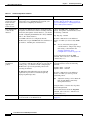
Initial Configuration Checklist
1-31
2-1
Setting Default Routes 2-3
Setting Default Routes for Network Routers 2-3
Setting the Default Route for Network Hosts 2-4
Cisco PIX Firewall and VPN Configuration Guide
78-15033-01
v
Contents
Configuring PIX Firewall Interfaces 2-4
Assigning an IP Address and Subnet Mask 2-5
Identifying the Interface Type 2-5
Changing Interface Names or Security Levels 2-6
Establishing Outbound Connectivity with NAT and PAT
Overview 2-7
How NAT and PAT Work 2-9
Configuring NAT and PAT 2-9
2-7
Configuring the PIX Firewall for Routing 2-12
Using RIP 2-12
Configuring RIP Static Routes on PIX Firewall 2-13
Using OSPF 2-14
Overview 2-14
Security Issues When Using OSPF 2-14
OSPF Features Supported 2-15
Restrictions and Limitations 2-16
Configuring OSPF on the PIX Firewall 2-17
Using OSPF in Public Networks 2-17
Using OSPF in Private and Public Networks 2-19
Viewing OSPF Configuration 2-20
Clearing OSPF Configuration 2-21
Testing and Saving Your Configuration
Testing Connectivity 2-22
Saving Your Configuration 2-24
2-21
Basic Configuration Examples 2-24
Two Interfaces Without NAT or PAT 2-25
Two Interfaces with NAT and PAT 2-27
Three Interfaces Without NAT or PAT 2-29
Three Interfaces with NAT and PAT 2-31
Using VLANs with the Firewall 2-33
Overview 2-33
Using Logical Interfaces 2-34
VLAN Security Issues 2-34
Configuring PIX Firewall with VLANs
Managing VLANs 2-36
Using Outside NAT 2-37
Overview 2-37
Simplifying Routing 2-38
Configuring Overlapping Networks
2-35
2-39
Cisco PIX Firewall and VPN Configuration Guide
vi
78-15033-01
Contents
Policy NAT 2-40
Limitations 2-42
Configuring Policy NAT 2-42
Configuring Global Translations 2-42
Configuring Static Translations 2-43
Enabling Stub Multicast Routing 2-43
Overview 2-44
Allowing Hosts to Receive Multicast Transmissions 2-44
Forwarding Multicasts from a Transmission Source 2-46
Configuring IGMP Timers 2-47
Setting the Query Interval 2-47
Setting Query Response Time 2-47
Clearing IGMP Configuration 2-47
Viewing and Debugging SMR 2-47
For More Information about Multicast Routing 2-48
CHAPTER
3
Controlling Network Access and Use
3-1
Enabling Server Access with Static NAT
Enabling Inbound Connections
3-1
3-2
Controlling Outbound Connectivity
3-4
Using the Static Command for Port Redirection
Overview 3-5
Port Redirection Configuration 3-6
Port Redirection Example 3-7
3-5
Using Authentication and Authorization 3-8
Configuring AAA 3-8
Enabling Secure Authentication of Web Clients
Configuring RADIUS Authorization 3-12
Using MAC-Based AAA Exemption 3-13
3-10
Access Control Configuration Example 3-14
Basic Configuration 3-14
Authentication and Authorization 3-16
Managing Access to Services 3-16
Adding Comments to ACLs 3-18
Using TurboACL 3-18
Overview 3-18
Globally Configuring TurboACL 3-19
Configuring Individual TurboACLs 3-19
Viewing TurboACL Configuration 3-20
Cisco PIX Firewall and VPN Configuration Guide
78-15033-01
vii
Contents
Downloading Access Lists 3-20
Configuring Downloadable ACLs 3-20
Downloading a Named Access List 3-21
Downloading an Access List Without a Name
Software Restrictions 3-23
3-22
Simplifying Access Control with Object Grouping 3-24
How Object Grouping Works 3-24
Using Subcommand Mode 3-25
Configuring and Using Object Groups with Access Control
Configuring Protocol Object Groups 3-28
Configuring Network Object Groups 3-28
Configuring Service Object Groups 3-28
Configuring ICMP-Type Object Groups 3-29
Nesting Object Groups 3-29
Displaying Configured Object Groups 3-30
Removing Object Groups 3-30
Filtering Outbound Connections 3-31
Filtering ActiveX Objects 3-31
Filtering Java Applets 3-32
Filtering URLs with Internet Filtering Servers 3-32
Overview 3-32
Identifying the Filtering Server 3-33
Buffering HTTP Replies for Filtered URLs 3-34
Filtering Long URLs with the Websense Filtering Server
Filtering HTTPS and FTP Sites 3-34
Configuring Filtering Policy 3-35
Filtering Long URLs 3-36
Viewing Filtering Statistics and Configuration 3-36
Configuration Procedure 3-38
CHAPTER
4
Using PIX Firewall in SOHO Networks
3-26
3-34
4-1
Using PIX Firewall as an Easy VPN Remote Device
Overview 4-2
Establishing Network Connectivity 4-4
Basic Configuration Procedure 4-4
Viewing Downloaded Configuration 4-5
Controlling Remote Administration 4-6
4-1
Cisco PIX Firewall and VPN Configuration Guide
viii
78-15033-01
Contents
Using Secure Unit Authentication 4-6
Overview 4-6
Establishing a Connection with SUA Enabled 4-7
Managing Connection Behavior with SUA 4-7
Using Individual User Authentication 4-8
Using X.509 Certificates 4-9
Verifying the DN of an Easy VPN Server 4-10
Using the PIX Firewall PPPoE Client 4-11
Overview 4-11
Configuring the PPPoE Client Username and Password
Enabling PPPoE on the PIX Firewall 4-13
Using PPPoE with a Fixed IP Address 4-13
Monitoring and Debugging the PPPoE Client 4-14
Using Related Commands 4-15
4-12
Using the PIX Firewall DCHP Server 4-15
Overview 4-15
Configuring the DHCP Server Feature 4-17
Using Cisco IP Phones with a DHCP Server 4-19
Using DHCP Relay
4-20
Using the PIX Firewall DHCP Client 4-21
Overview 4-21
Configuring the DHCP Client 4-21
Releasing and Renewing the DHCP Lease 4-22
Monitoring and Debugging the DHCP Client 4-22
CHAPTER
5
Configuring Application Inspection (Fixup)
How Application Inspection Works
Using the fixup Command
5-1
5-1
5-4
Basic Internet Protocols 5-6
DNS 5-6
FTP 5-7
HTTP 5-9
ICMP 5-9
IPSec 5-9
PPTP 5-10
SMTP 5-11
TFTP 5-11
Application Inspection 5-12
Sample Configuration 5-13
Cisco PIX Firewall and VPN Configuration Guide
78-15033-01
ix
Contents
Voice Over IP 5-14
CTIQBE 5-14
CU-SeeMe 5-15
H.323 5-16
Overview 5-16
Multiple Calls on One Call Signalling Connection 5-16
Viewing Connection Status 5-17
Technical Background 5-17
MGCP 5-18
Overview 5-18
Enabling MGCP Application Inspection 5-19
Configuration for Multiple Call Agents and Gateways 5-19
Viewing MGCP Information 5-20
SCCP 5-20
Overview 5-20
Using PAT with SCCP 5-21
Using SCCP with Cisco CallManager on a Higher Security Interface
Problems Occur with Fragmented SCCP Packets 5-22
Viewing SCCP Information 5-22
SIP 5-22
Overview 5-23
Allowing Outside Phones to Place an Inside Phone on Hold 5-23
Instant Messaging (IM) 5-24
Viewing SIP Information 5-24
Technical Background 5-24
Multimedia Applications 5-25
Netshow 5-25
UDP Stream 5-25
TCP Stream 5-26
Real Time Streaming Protocol (RTSP)
VDO LIVE 5-27
Database and Directory Support 5-27
ILS and LDAP 5-28
Network File System and Sun RPC
Oracle SQL*Net (V1/V2) 5-30
5-22
5-26
5-29
Management Protocols 5-30
Internet Control Message Protocol 5-31
Remote Shell 5-31
X Display Manager Control Protocol 5-31
Cisco PIX Firewall and VPN Configuration Guide
x
78-15033-01
Contents
CHAPTER
6
Configuring IPSec and Certification Authorities
How IPSec Works
6-1
6-1
Internet Key Exchange (IKE) 6-2
IKE Overview 6-2
Configuring IKE 6-4
Disabling IKE 6-6
Using IKE with Pre-Shared Keys
6-6
Using Certification Authorities 6-7
CA Overview 6-8
Public Key Cryptography 6-8
Certificates Provide Scalability 6-8
Supported CA Servers 6-9
Configuring the PIX Firewall to Use Certificates 6-9
Verifying the Distinguished Name of a Certificate 6-12
Configuring IPSec 6-13
IPSec Overview 6-14
Transform Sets 6-15
Crypto Maps 6-15
Applying Crypto Maps to Interfaces
Access Lists 6-17
IPSec SA Lifetimes 6-19
Basic IPSec Configuration 6-20
Diffie-Hellman Group 5 6-22
6-17
Using Dynamic Crypto Maps 6-23
Site-to-Site Redundancy 6-25
Using NAT Traversal 6-25
Manual Configuration of SAs
6-26
Viewing IPSec Configuration
6-29
Clearing SAs
CHAPTER
7
6-29
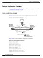
Site-to-Site VPN Configuration Examples
7-1
Using Pre-Shared Keys 7-1
Scenario Description 7-1
Configuring PIX Firewall 1 with VPN Tunneling 7-2
Configuring PIX Firewall 2 for VPN Tunneling 7-5
Cisco PIX Firewall and VPN Configuration Guide
78-15033-01
xi
Contents
Using PIX Firewall with a VeriSign CA 7-7
Scenario Description 7-7
Configuring PIX Firewall 1 with a VeriSign CA
Configuring PIX Firewall 2 with a VeriSign CA
Using PIX Firewall with an In-House CA 7-13
Scenario Description 7-14
Configuring PIX Firewall 1 for an In-House CA
Configuring PIX Firewall 2 for an In-House CA
7-8
7-11
7-15
7-18
Using an Encrypted Tunnel to Obtain Certificates 7-20
Establishing a Tunnel Using a Pre-Shared Key 7-21
PIX Firewall 1 Configuration 7-21
PIX Firewall 2 Configuration 7-23
Establishing a Tunnel with a Certificate 7-24
PIX Firewall 1 Configuration 7-24
PIX Firewall 2 Configuration 7-25
Connecting to a Catalyst 6500 and Cisco 7600 Series IPSec VPN Services Module
Scenario Description 7-25
Configuring IPSec Using a Trunk Port 7-26
Configuring IPSec Using a Routed Port 7-30
Verifying Your Configuration 7-35
7-25
Manual Configuration with NAT 7-35
PIX Firewall 1 Configuration 7-35
PIX Firewall 2 Configuration 7-37
CHAPTER
8
Managing VPN Remote Access
8-1
Using the PIX Firewall as an Easy VPN Server 8-1
Overview 8-2
Enabling Redundancy 8-4
Configuring Secure Unit Authentication 8-4
Configuring Individual User Authentication 8-4
Bypassing AAA Authentication 8-5
Configuring Extended Authentication (Xauth)
8-5
Configuring Easy VPN Remote Devices with IKE Mode Config
8-7
Using an Easy VPN Remote Device with Pre-Shared Keys 8-8
Scenario Description 8-8
Configuring the PIX Firewall 8-10
Configuring the Easy VPN Remote Software Client 8-13
Cisco PIX Firewall and VPN Configuration Guide
xii
78-15033-01
Contents
Using an Easy VPN Remote Device with Digital Certificates 8-13
Client Verification of the Easy VPN Server Certificate 8-14
Scenario Description 8-14
Configuring the PIX Firewall 8-16
Configuring the Easy VPN Remote Software Client 8-19
Using PPTP for Remote Access 8-20
Overview 8-20
PPTP Configuration 8-21
PPTP Configuration Example 8-21
CHAPTER
9
Accessing and Monitoring PIX Firewall
9-1
Connecting to PIX Firewall Over a VPN Tunnel
9-1
Command Authorization and LOCAL User Authentication 9-2
Privilege Levels 9-2
User Authentication 9-3
Creating User Accounts in the LOCAL Database 9-3
User Authentication Using the LOCAL Database 9-4
Viewing the Current User Account 9-5
Command Authorization 9-5
Overview 9-6
Configuring LOCAL Command Authorization 9-6
Enabling LOCAL Command Authorization 9-7
Viewing LOCAL Command Authorization Settings 9-7
TACACS+ Command Authorization 9-8
Recovering from Lockout 9-9
Configuring PIX Firewall Banners
9-10
Using Network Time Protocol 9-10
Overview 9-11
Enabling NTP 9-11
Viewing NTP Status and Configuration
9-12
Managing the PIX Firewall Clock 9-15
Viewing System Time 9-15
Setting the System Clock 9-15
Setting Daylight Savings Time and Timezones
9-15
Using Telnet for Remote System Management 9-16
Configuring Telnet Console Access to the Inside Interface
9-17
Cisco PIX Firewall and VPN Configuration Guide
78-15033-01
xiii
Contents
Allowing a Telnet Connection to the Outside Interface 9-18
Overview 9-18
Using Telnet with an Easy VPN Remote Device 9-18
Using Cisco Secure VPN Client Version 1.1 9-19
Using Telnet 9-20
Trace Channel Feature 9-21
Using SSH for Remote System Management 9-21
Overview 9-22
Obtaining an SSH Client 9-22
Identifying the Host Using an SSH Client 9-23
Configuring Authentication for an SSH Client 9-24
Connecting to the PIX Firewall with an SSH Client 9-24
Viewing SSH Status 9-24
Enabling Auto Update Support 9-25
Overview 9-25
Identifying the Auto Update Server 9-25
Managing Auto Update Support 9-26
Viewing the Auto Update Configuration 9-26
Capturing Packets 9-27
Overview 9-27
Configuration Procedure 9-27
Packet Capture Output Formats 9-29
Packet Capture Examples 9-30
Saving Crash Information to Flash Memory
9-31
Using Syslog 9-32
Enabling Logging to Syslog Servers 9-33
Changing Syslog Message Levels 9-33
Disabling Syslog Messages 9-34
Viewing Modified Message Levels 9-34
Logging Access Control List Activity 9-35
Overview 9-35
Configuration 9-35
Logging Behavior 9-37
Syslog Message Format 9-38
Managing IDS Syslog Messages 9-39
Using SNMP 9-41
Overview 9-41
MIB Support 9-42
SNMP CPU Utilization
9-42
Cisco PIX Firewall and VPN Configuration Guide
xiv
78-15033-01
Contents
SNMP Usage Notes 9-43
SNMP Traps 9-44
Receiving Requests and Sending Syslog Traps
Compiling Cisco Syslog MIB Files 9-45
Using the Firewall and Memory Pool MIBs 9-46
ipAddrTable Notes 9-46
Viewing Failover Status 9-47
Verifying Memory Usage 9-48
Viewing The Connection Count 9-49
Viewing System Buffer Usage 9-50
CHAPTER
10
Using PIX Firewall Failover
9-44
10-1
Failover System Requirements
10-2
Understanding Failover 10-3
Overview 10-3
Network Connections 10-4
Failover and State Links 10-4
Failover Link 10-4
State Link 10-5
Primary and Secondary Vs. Active and Standby
Configuration Replication 10-6
Failover Triggers 10-7
10-6
Failover Configuration Prerequisites 10-8
Configuring Switches to Support Failover 10-8
Preconfiguring the PIX Firewall for Failover 10-9
Configuring Cable-Based Failover
10-9
Configuring LAN-Based Failover 10-11
Configuring the Primary Unit 10-12
Configuring the Secondary Unit 10-15
Verifying the Failover Configuration 10-16
Using the Show Failover Command 10-17
Testing the Failover Functionality 10-19
Forcing Failover
Disabling Failover
10-20
10-20
Monitoring Failover 10-20
Failover Syslog Messages 10-21
SNMP 10-21
Debugging Command 10-21
ACTIVE Light 10-21
Cisco PIX Firewall and VPN Configuration Guide
78-15033-01
xv
Contents
Frequently Asked Failover Questions 10-21
Configuration Replication Questions 10-21
Basic Failover Questions 10-22
Cable-Based Failover Questions 10-23
LAN-Based Failover Questions 10-23
Stateful Failover Questions 10-24
Failover Configuration Examples 10-24
Cable-Based Failover Example 10-25
LAN-Based Failover Example 10-26
CHAPTER
11
Changing Feature Licenses and System Software
11-1
Upgrading Your License by Entering a New Activation Key
Obtaining an Activation Key 11-2
Entering a New Activation Key 11-2
Troubleshooting the License Upgrade 11-4
11-2
Using HTTP to Copy Software and Configurations 11-5
Copying PIX Firewall Configurations 11-6
Copying a PIX Firewall Image or PDM Software 11-6
Downloading the Current Software 11-6
Getting a TFTP Server 11-7
Downloading Software from the Web 11-7
Downloading Software with FTP 11-8
Installing and Recovering PIX Firewall Software 11-9
Installing Image Software from the Command Line 11-9
Using Monitor Mode to Recover the PIX Firewall Image 11-9
Using Boothelper 11-10
Get the Boothelper Binary Image 11-11
Preparing a Boothelper Diskette with UNIX, Solaris, or LINUX 11-11
Preparing a Boothelper Diskette on a Windows System 11-12
Downloading an Image with Boothelper 11-12
Downgrading to a Previous Software Version
11-13
Upgrading Failover Systems from a Previous Version 11-14
Upgrading Failover Systems Using Monitor Mode 11-14
Upgrading Failover Systems Using Boothelper 11-14
TFTP Download Error Codes
11-15
Cisco PIX Firewall and VPN Configuration Guide
xvi
78-15033-01
Contents
APPENDIX
A
Acronyms and Abbreviations
APPENDIX
B
Configuration Examples for Other Remote Access Clients
B-1
Xauth with RSA Ace/Server and RSA SecurID B-1
Terminology B-1
Introduction B-2
PIX Firewall Configuration B-3
SecurID with Cisco VPN Client Version 3.x B-4
Token Enabled B-4
Next Tokencode Mode B-4
New PIN Mode B-5
SecurID with Cisco VPN 3000 Client Version 2.5 B-5
Token Enabled B-6
Next Tokencode Mode B-6
New PIN Mode B-6
SecurID with Cisco Secure VPN Client Version 1.1 (3DES)
Token Enabled B-7
Next Tokencode Mode B-8
New PIN Mode B-8
L2TP with IPSec in Transport Mode B-8
L2TP Overview B-9
IPSec Transport and Tunnel Modes B-9
Configuring L2TP with IPSec in Transport Mode
Windows 2000 Client with IPSec and L2TP
Overview B-12
Configuring the PIX Firewall B-12
Enabling IPSec Debug B-15
Getting Additional Information B-15
B-1
B-7
B-10
B-11
Using Cisco VPN Client Version 1.1 B-16
Configuring the PIX Firewall B-17
Configuring the Cisco Secure VPN Client Version 1.1 B-19
Making an Exception to Xauth for a Site-to-Site VPN Peer B-21
Making an Exception to IKE Mode Config for Site-to-Site VPN Peers
APPENDIX
C
MS-Exchange Firewall Configuration
C-1
Configuring the Microsoft Exchange Servers
Configuring the PIX Firewall
Configuring the Outside Server
B-21
C-1
C-2
C-3
Cisco PIX Firewall and VPN Configuration Guide
78-15033-01
xvii
Contents
Configuring the Inside Server
C-3
Configuring Both Systems After Rebooting
APPENDIX
D
TCP/IP Reference Information
IP Addresses
Ports
C-4
D-1
D-1
D-2
Protocols and Applications D - 5
Supported Multimedia Applications D - 6
Supported Protocols and Applications D - 6
Using Subnet Masks D - 7
Masks D - 7
Uses for Subnet Information
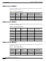
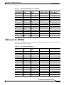
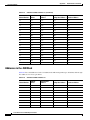
Using Limited IP Addresses
Addresses in the .128 Mask
Addresses in the .192 Mask
Addresses in the .224 Mask
Addresses in the .240 Mask
Addresses in the .248 Mask
Addresses in the .252 Mask
APPENDIX
E
D-9
D-9
D-9
D - 10
D - 10
D - 10
D - 11
D - 12
Supported VPN Standards and Security Proposals
IPSec
E-1
E-1
Internet Key Exchange (IKE)
E-2
Certification Authorities (CA)
Supported Easy VPN Proposals
E-3
E-3
INDEXndex
INDEX
Cisco PIX Firewall and VPN Configuration Guide
xviii
78-15033-01
About This Guide
This preface introduces the Cisco PIX Firewall and VPN Configuration Guide and contains the
following sections:
•
Document Objectives, page xix
•
Audience, page xix
•
Document Organization, page xx
•
Document Conventions, page xxi
•
Obtaining Documentation, page xxi
•
Obtaining Technical Assistance, page xxiii
•
Obtaining Additional Publications and Information, page xxiv
Document Objectives
This document describes how to configure the Cisco PIX Firewall to protect your network from
unauthorized use and to establish Virtual Private Networks (VPNs) to connect remote sites and users to
your network.
Audience
This guide is for network managers who perform any of the following tasks:
•
Managing network security
•
Installing and configuring firewalls
•
Managing default and static routes, and TCP and UDP services
Use this guide with the installation guide supplied with your PIX Firewall unit.
Cisco PIX Firewall and VPN Configuration Guide
78-15033-01
xix
About This Guide
Document Organization
Document Organization
This guide includes the following chapters and appendixes:
•
Chapter 1, “Getting Started,” describes the benefits provided by PIX Firewall and the technology
used to implement each feature.
•
Chapter 2, “Establishing Connectivity,” describes how to establish secure connectivity between an
unprotected network, such as the public Internet, and one or more protected networks.
•
Chapter 3, “Controlling Network Access and Use,” describes how to control connectivity between
unprotected and protected networks and how to control network use through filtering and other
PIX Firewall features.
•
Chapter 4, “Using PIX Firewall in SOHO Networks,” describes how to configure the PIX Firewall
as a Cisco Easy VPN Remote device and as a Point-to-Point-Protocol over Ethernet (PPPoE) client.
It also describes how to use the PIX Firewall as a Dynamic Host Configuration Protocol (DHCP)
server, client, and relay agent.
•
Chapter 5, “Configuring Application Inspection (Fixup),” describes how the application inspection
function enables the secure use of specific applications and services.
•
Chapter 6, “Configuring IPSec and Certification Authorities,” describes how to configure the
PIX Firewall to support Virtual Private Networks (VPNs).
•
Chapter 7, “Site-to-Site VPN Configuration Examples,” provides examples of using PIX Firewall to
establish site-to-site VPNs.
•
Chapter 8, “Managing VPN Remote Access,” describes how to configure the PIX Firewall as an
Easy VPN Server and how to configure Easy VPN Remote software clients. It also describes how to
configure the PIX Firewall to support remote PPTP clients.
•
Chapter 9, “Accessing and Monitoring PIX Firewall,” describes how to implement, configure, and
integrate PIX Firewall system management tools.
•
Chapter 10, “Using PIX Firewall Failover,” describes how to implement and configure the failover
feature.
•
Chapter 11, “Changing Feature Licenses and System Software,” describes how to upgrade or
downgrade your PIX Firewall software image and feature license.
•
Appendix A, “Acronyms and Abbreviations,” lists the acronyms and abbreviations used in this
guide.
•
Appendix B, “Configuration Examples for Other Remote Access Clients” describes how to use
PIX Firewall with different remote access clients, including MS Windows 2000/L2TP and Cisco
Secure VPN Client Version 1.1.
•
Appendix C, “MS-Exchange Firewall Configuration,” describes how to configure PIX Firewall to
handle mail transfers across the PIX Firewall from Windows NT Servers on protected and
unprotected networks.
•
Appendix D, “TCP/IP Reference Information,” lists the IP addresses associated with each subnet
mask value.
•
Appendix E, “Supported VPN Standards and Security Proposals,”lists the standards supported for
IPSec, IKE, and certification authorities (CA).
Cisco PIX Firewall and VPN Configuration Guide
xx
78-15033-01
About This Guide
Document Conventions
Document Conventions
Command descriptions use these conventions:
•
Braces ({ }) indicate a required choice.
•
Square brackets ([ ]) indicate optional elements.
•
Vertical bars ( | ) separate alternative, mutually exclusive elements.
•
Boldface indicates commands and keywords that are entered literally as shown.
•
Italics indicate arguments for which you supply values.
Examples use these conventions:
•
Examples depict screen displays and the command line in screen font.
•
Information you need to enter in examples is shown in boldface screen font.
•
Variables for which you must supply a value are shown in italic screen font.
Graphic user interface access uses these conventions:
•
Boldface indicates buttons and menu items.
•
Selecting a menu item (or screen) is indicated by the following convention:
Click Start>Settings>Control Panel.
Note
Means reader take note. Notes contain helpful suggestions or references to material not
covered in the manual.
Obtaining Documentation
Cisco provides several ways to obtain documentation, technical assistance, and other technical
resources. These sections explain how to obtain technical information from Cisco Systems.
Cisco.com
You can access the most current Cisco documentation on the World Wide Web at this URL:
http://www.cisco.com/univercd/home/home.htm
You can access the Cisco website at this URL:
http://www.cisco.com
International Cisco web sites can be accessed from this URL:
http://www.cisco.com/public/countries_languages.shtml
Cisco PIX Firewall and VPN Configuration Guide
78-15033-01
xxi
About This Guide
Obtaining Documentation
Documentation CD-ROM
Cisco documentation and additional literature are available in a Cisco Documentation CD-ROM
package, which may have shipped with your product. The Documentation CD-ROM is updated monthly
and may be more current than printed documentation. The CD-ROM package is available as a single unit
or through an annual subscription.
Registered Cisco.com users can order the Documentation CD-ROM (product number
DOC-CONDOCCD=) through the online Subscription Store:
http://www.cisco.com/go/subscription
Ordering Documentation
You can find instructions for ordering documentation at this URL:
http://www.cisco.com/univercd/cc/td/doc/es_inpck/pdi.htm
You can order Cisco documentation in these ways:
•
Registered Cisco.com users (Cisco direct customers) can order Cisco product documentation from
the Networking Products MarketPlace:
http://www.cisco.com/en/US/partner/ordering/index.shtml
•
Registered Cisco.com users can order the Documentation CD-ROM (Customer Order Number
DOC-CONDOCCD=) through the online Subscription Store:
http://www.cisco.com/go/subscription
•
Nonregistered Cisco.com users can order documentation through a local account representative by
calling Cisco Systems Corporate Headquarters (California, U.S.A.) at 408 526-7208 or, elsewhere
in North America, by calling 800 553-NETS (6387).
Documentation Feedback
You can submit comments electronically on Cisco.com. On the Cisco Documentation home page, click
Feedback at the top of the page.
You can e-mail your comments to [email protected].
You can submit your comments by mail by using the response card behind the front cover of your
document or by writing to the following address:
Cisco Systems
Attn: Customer Document Ordering
170 West Tasman Drive
San Jose, CA 95134-9883
We appreciate your comments.
Cisco PIX Firewall and VPN Configuration Guide
xxii
78-15033-01
About This Guide
Obtaining Technical Assistance
Obtaining Technical Assistance
Cisco provides Cisco.com, which includes the Cisco Technical Assistance Center (TAC) Website, as a
starting point for all technical assistance. Customers and partners can obtain online documentation,
troubleshooting tips, and sample configurations from the Cisco TAC website. Cisco.com registered users
have complete access to the technical support resources on the Cisco TAC website, including TAC tools
and utilities.
Cisco.com
Cisco.com offers a suite of interactive, networked services that let you access Cisco information,
networking solutions, services, programs, and resources at any time, from anywhere in the world.
Cisco.com provides a broad range of features and services to help you with these tasks:
•
Streamline business processes and improve productivity
•
Resolve technical issues with online support
•
Download and test software packages
•
Order Cisco learning materials and merchandise
•
Register for online skill assessment, training, and certification programs
To obtain customized information and service, you can self-register on Cisco.com at this URL:
http://www.cisco.com
Technical Assistance Center
The Cisco TAC is available to all customers who need technical assistance with a Cisco product,
technology, or solution. Two levels of support are available: the Cisco TAC website and the Cisco TAC
Escalation Center. The avenue of support that you choose depends on the priority of the problem and the
conditions stated in service contracts, when applicable.
We categorize Cisco TAC inquiries according to urgency:
•
Priority level 4 (P4)—You need information or assistance concerning Cisco product capabilities,
product installation, or basic product configuration.
•
Priority level 3 (P3)—Your network performance is degraded. Network functionality is noticeably
impaired, but most business operations continue.
•
Priority level 2 (P2)—Your production network is severely degraded, affecting significant aspects
of business operations. No workaround is available.
•
Priority level 1 (P1)—Your production network is down, and a critical impact to business operations
will occur if service is not restored quickly. No workaround is available.
Cisco TAC Website
You can use the Cisco TAC website to resolve P3 and P4 issues yourself, saving both cost and time. The
site provides around-the-clock access to online tools, knowledge bases, and software. To access the
Cisco TAC website, go to this URL:
http://www.cisco.com/tac
Cisco PIX Firewall and VPN Configuration Guide
78-15033-01
xxiii
About This Guide
Obtaining Additional Publications and Information
All customers, partners, and resellers who have a valid Cisco service contract have complete access to
the technical support resources on the Cisco TAC website. Some services on the Cisco TAC website
require a Cisco.com login ID and password. If you have a valid service contract but do not have a login
ID or password, go to this URL to register:
http://tools.cisco.com/RPF/register/register.do
If you are a Cisco.com registered user, and you cannot resolve your technical issues by using the Cisco
TAC website, you can open a case online at this URL:
http://www.cisco.com/en/US/support/index.html
If you have Internet access, we recommend that you open P3 and P4 cases through the Cisco TAC
website so that you can describe the situation in your own words and attach any necessary files.
Cisco TAC Escalation Center
The Cisco TAC Escalation Center addresses priority level 1 or priority level 2 issues. These
classifications are assigned when severe network degradation significantly impacts business operations.
When you contact the TAC Escalation Center with a P1 or P2 problem, a Cisco TAC engineer
automatically opens a case.
To obtain a directory of toll-free Cisco TAC telephone numbers for your country, go to this URL:
http://www.cisco.com/warp/public/687/Directory/DirTAC.shtml
Before calling, please check with your network operations center to determine the level of Cisco support
services to which your company is entitled: for example, SMARTnet, SMARTnet Onsite, or Network
Supported Accounts (NSA). When you call the center, please have available your service agreement
number and your product serial number.
Obtaining Additional Publications and Information
Information about Cisco products, technologies, and network solutions is available from various online
and printed sources.
•
The Cisco Product Catalog describes the networking products offered by Cisco Systems as well as
ordering and customer support services. Access the Cisco Product Catalog at this URL:
http://www.cisco.com/en/US/products/products_catalog_links_launch.html
•
Cisco Press publishes a wide range of networking publications. Cisco suggests these titles for new
and experienced users: Internetworking Terms and Acronyms Dictionary, Internetworking
Technology Handbook, Internetworking Troubleshooting Guide, and the Internetworking Design
Guide. For current Cisco Press titles and other information, go to Cisco Press online at this URL:
http://www.ciscopress.com
•
Packet magazine is the Cisco monthly periodical that provides industry professionals with the latest
information about the field of networking. You can access Packet magazine at this URL:
http://www.cisco.com/en/US/about/ac123/ac114/about_cisco_packet_magazine.html
•
iQ Magazine is the Cisco monthly periodical that provides business leaders and decision makers
with the latest information about the networking industry. You can access iQ Magazine at this URL:
http://business.cisco.com/prod/tree.taf%3fasset_id=44699&public_view=true&kbns=1.html
Cisco PIX Firewall and VPN Configuration Guide
xxiv
78-15033-01
About This Guide
Obtaining Additional Publications and Information
•
Internet Protocol Journal is a quarterly journal published by Cisco Systems for engineering
professionals involved in the design, development, and operation of public and private internets and
intranets. You can access the Internet Protocol Journal at this URL:
http://www.cisco.com/en/US/about/ac123/ac147/about_cisco_the_internet_protocol_journal.html
•
Training—Cisco offers world-class networking training, with current offerings in network training
listed at this URL:
http://www.cisco.com/en/US/learning/le31/learning_recommended_training_list.html
Cisco PIX Firewall and VPN Configuration Guide
78-15033-01
xxv
About This Guide
Obtaining Additional Publications and Information
Cisco PIX Firewall and VPN Configuration Guide
xxvi
78-15033-01
C H A P T E R
1
Getting Started
The Cisco PIX Firewall lets you establish stateful firewall protection and secure VPN access with a
single device. PIX Firewall provides a scalable security solution with failover support available for
selected models to provide maximum reliability. PIX Firewall uses a specialized operating system that
is more secure and easier to maintain than software firewalls that use a general-purpose operating
system, which are subject to frequent threats and attacks.
This chapter describes how you can use the PIX Firewall to protect your network assets and to establish
secure VPN access. It contains the following sections:
•
Controlling Network Access, page 1-1
•
Protecting Your Network from Attack, page 1-8
•
Supporting Specific Protocols and Applications, page 1-11
•
Creating a Virtual Private Network, page 1-14
•
Using PIX Firewall in a Small Office, Home Office Environment, page 1-19
•
Accessing and Monitoring PIX Firewall, page 1-20
•
PIX Firewall Failover, page 1-24
•
Upgrading the PIX Firewall OS and License, page 1-24
•
Using the Command-Line Interface, page 1-25
•
Before You Start Configuring PIX Firewall, page 1-31
•
Where to Go from Here, page 1-31
Controlling Network Access
This section describes the network firewall functionality provided by PIX Firewall. It includes the
following topics:
•
How the PIX Firewall Works, page 1-2
•
Adaptive Security Algorithm, page 1-3
•
Multiple Interfaces and Security Levels, page 1-4
•
How Data Moves Through the PIX Firewall, page 1-4
•
Address Translation, page 1-5
•
Cut-Through Proxy, page 1-6
Cisco PIX Firewall and VPN Configuration Guide
78-15033-01
1-1
Chapter 1
Getting Started
Controlling Network Access
•
Access Control, page 1-6
•
VLAN Support, page 1-8
Chapter 2, “Establishing Connectivity” provides configuration instructions for establishing network
connectivity through the PIX Firewall. Chapter 3, “Controlling Network Access and Use” provides
configuration instructions for using the PIX Firewall to control network connectivity.
How the PIX Firewall Works
The PIX Firewall protects an inside network from unauthorized access by users on an outside network,
such as the public Internet. Most PIX Firewall models can optionally protect one or more perimeter
networks, also known as demilitarized zones (DMZs). Access to the perimeter network is typically less
restricted than access to the inside network, but more restricted than access to the outside network.
Connections between the inside, outside, and perimeter networks are controlled by the PIX Firewall.
To effectively use a firewall in your organization, you need a security policy to ensure that all traffic from
the protected networks passes only through the firewall to the unprotected network. You can then control
who may access the networks with which services, and how to implement your security policy using the
features that the PIX Firewall provides.
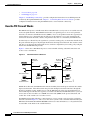
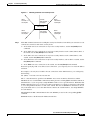
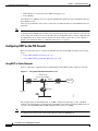
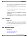
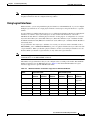
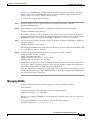
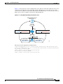
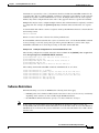
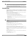
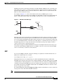
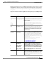
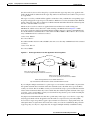
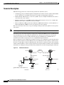
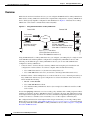
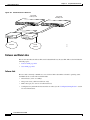
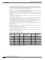
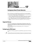
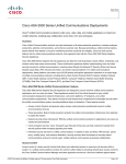
Figure 1-1 shows how a PIX Firewall protects a network while allowing outbound connections and
secure access to the Internet.
Figure 1-1
The PIX Firewall in a Network
Outbound
connections
OK
Router
Inside
No direct
inbound
connections
Internet
PIX
Firewall
Perimeter
Outside
Internet
attached router
Server 1
Protected clients
Server 2
Internet
accesible server
S6243
Protected servers
Within this architecture, the PIX Firewall forms the boundary between the protected networks and the
unprotected networks. All traffic between the protected and unprotected networks flows through the
firewall to maintain security. Traffic may not exit the PIX Firewall on the same network interface it
entered. The unprotected network is typically accessible to the Internet. The PIX Firewall lets you locate
servers such as those for Web access, SNMP, electronic mail (SMTP) in the protected network, and
control who on the outside can access these servers.
For PIX Firewall models with three or more interfaces, server systems can be located on a perimeter
network as shown in Figure 1-1, and access to the server systems can be controlled and monitored by the
PIX Firewall. The PIX 501 and PIX 506/506E each have two network interfaces, so all systems must be
located either on the inside or the outside interfaces.
Cisco PIX Firewall and VPN Configuration Guide
1-2
78-15033-01
Chapter 1
Getting Started
Controlling Network Access
The PIX Firewall also lets you implement your security policies for connection to and from the inside
network.
Typically, the inside network is an organization's own internal network, or intranet, and the outside
network is the Internet, but the PIX Firewall can also be used within an intranet to isolate or protect one
group of internal computing systems and users from another.
The perimeter network can be configured to be as secure as the inside network or with varying security
levels. Security levels are assigned numeric values from 0, the least secure, to 100, the most secure. The
outside interface is always 0 and the inside interface is always 100. The perimeter interfaces can be any
security level from 1 to 99.
Both the inside and perimeter networks are protected with the PIX Firewall's Adaptive Security
Algorithm (ASA). The inside, perimeter, and outside interfaces can listen to RIP routing updates, and
all interfaces can broadcast a RIP default route if required.
Adaptive Security Algorithm
The Adaptive Security Algorithm (ASA) is a stateful approach to security. Every inbound packet is
checked against the Adaptive Security Algorithm and against connection state information in memory.
This stateful approach to security is regarded in the industry as being far more secure than a stateless
packet screening approach.
ASA allows one way (inside to outside) connections without an explicit configuration for each internal
system and application. ASA is always in operation, monitoring return packets to ensure they are valid.
It actively randomizes TCP sequence numbers to minimize the risk of TCP sequence number attack.
Note
The PIX Firewall checks the TCP sequence number and ensures that it fits within an acceptable range.
ASA applies to the dynamic translation slots and static translation slots. You create static translation
slots with the static command and dynamic translation slots with the global command. Collectively,
both types of translation slots are referred to as “xlates.” ASA follows these rules:
•
No packets can traverse the PIX Firewall without a connection and state.
•
Traffic may not exit the PIX Firewall on the same network interface it entered.
•
Outbound connections or states are allowed, except those specifically denied by access control lists.
An outbound connection is one where the originator or client is on a higher security interface than
the receiver or server. The highest security interface is always the inside interface and the lowest is
the outside interface. Any perimeter interfaces can have security levels between the inside and
outside values.
•
Inbound connections or states are denied, except those specifically allowed. An inbound connection
or state is one where the originator or client is on a lower security interface/network than the receiver
or server. You can apply multiple exceptions to a single xlate (translation). This lets you permit
access from an arbitrary machine, network, or any host on the Internet to the host defined by the
xlate.
•
All ICMP packets are denied unless specifically permitted.
•
All attempts to circumvent the previous rules are dropped and a message is sent to the syslog.
Cisco PIX Firewall and VPN Configuration Guide
78-15033-01
1-3
Chapter 1
Getting Started
Controlling Network Access
PIX Firewall handles UDP data transfers in a manner similar to TCP. Special handling allows DNS,
archie, StreamWorks, H.323, and RealAudio to work securely. The PIX Firewall creates UDP
“connection” state information when a UDP packet is sent from the inside network. Response packets
resulting from this traffic are accepted if they match the connection state information. The connection
state information is deleted after a short period of inactivity.
For more information about how ASA works and how you can configure application inspection with
different types of applications, refer to Chapter 5, “Configuring Application Inspection (Fixup).”
Multiple Interfaces and Security Levels
All PIX Firewalls provide at least two interfaces, which by default, are called outside and inside, and are
assigned a security level of 0 and 100, respectively. A lower security level indicates that the interface is
relatively less protected than the higher security level. Typically, the outside interface is connected to the
public Internet, while the inside interface is connected to your private network and is protected from
public access.
Many PIX Firewall models provide up to eight interfaces, to let you create one or more perimeter
networks, also called bastion networks or demilitarized zones (DMZs). A DMZ is a network that is more
secure than the outside interface but less secure than the inside interface. You can assign security levels
to your perimeter networks from 0 to 100. Typically, you put mail servers or web servers that need to be
accessed by users on the public Internet in a DMZ to provide some protection, but without jeopardizing
the resources on your internal network.
How Data Moves Through the PIX Firewall
When an outbound packet arrives at a PIX Firewall higher security level interface (security levels can be
viewed with the show nameif command), the PIX Firewall checks to see if the packet is valid based on
the Adaptive Security Algorithm, and then whether or not previous packets have come from that host. If
not, then the packet is for a new connection, and PIX Firewall creates a translation slot in its state table
for the connection. The information that PIX Firewall stores in the translation slot includes the inside IP
address and a globally unique IP address assigned by Network Address Translation (NAT), Port Address
Translation (PAT), or Identity (which uses the inside address as the outside address). The PIX Firewall
then changes the packet's source IP address to the globally unique address, modifies the checksum and
other fields as required, and forwards the packet to the lower security level interface.
When an inbound packet arrives at an external interface such as the outside interface, it first passes the
PIX Firewall Adaptive Security criteria. If the packet passes the security tests, the PIX Firewall removes
the destination IP address, and the internal IP address is inserted in its place. The packet is forwarded to
the protected interface.
Note
Traffic may not exit the PIX Firewall on the same network interface it entered. This condition results in
the following message in the system log:
%PIX-7-106011: Deny inbound (No xlate) chars
Explanation
This is a connection-related message. This message occurs when a
packet is sent to the same interface that it arrived on. This usually indicates that a
security breach is occurring. When the PIX Firewall receives a packet, it tries to
establish a translation slot based on the security policy you set with the global and
conduit commands, and your routing policy set with the route command.
Cisco PIX Firewall and VPN Configuration Guide
1-4
78-15033-01
Chapter 1
Getting Started
Controlling Network Access
Address Translation
The Network Address Translation (NAT) feature works by substituting, or translating, host addresses on
one interface with a “global address” associated with another interface. This protects internal host
addresses from being exposed on other network interfaces. To understand whether you want to use NAT,
decide if you want to expose internal addresses on other network interfaces connected to the
PIX Firewall. If you choose to protect internal host addresses using NAT, you identify the pool of
addresses you want to use for translation.
Note
Beginning with Version 6.2 of the PIX Firewall, NAT is also available for translating outside addresses.
This helps to simplify network routing by controlling the addresses that can appear on the inside
network.
If the addresses that you want to protect access only other networks within your organization, you can
use any set of “private” addresses for the pool of translation addresses. For example, if you want to
protect the host addresses on the Finance Department’s network (connected to the inside interface on the
PIX Firewall) from exposure when connecting to the Sales Department network (connected to the
perimeter interface on the PIX Firewall), you can set up translation using any available set of addresses
on the Sales network. The effect is that hosts on the Finance network appear as local addresses on the
Sales network.
If the addresses that you want to protect require Internet access, you use only NIC-registered addresses
(official Internet addresses registered with the Network Information Center for your organization) for
the pool of translation addresses. For example, if you want to protect host addresses on the Sales network
(connected to a perimeter interface of the PIX Firewall) from exposure when making connections to the
Internet (accessible through the outside interface of the PIX Firewall), you can set up translation using
a pool of registered addresses on the outside interface. The effect is that hosts on the Internet see only
the Internet addresses for the Sales network, not the addresses on the perimeter interface.
If you are installing the PIX Firewall in an established network that has host- or network-registered
addresses, you might not want to perform translation for those hosts or networks because that would
require using another registered address for the translation.
When considering NAT, it is also important to consider whether you have an equal number of addresses
for internal hosts. If not, some internal hosts might not get network access when making a connection.
In this case you can either apply for additional NIC-registered addresses or use Port Address Translation
(PAT). PAT uses a single external address to manage up to 64,000 concurrent connections.
For inside systems, NAT translates the source IP address of outgoing packets (defined in RFC 1631). It
supports both dynamic and static translation. NAT allows inside systems to be assigned private addresses
(defined in RFC 1918), or to retain existing invalid addresses. NAT also provides additional security by
hiding the real network identity of internal systems from the outside network.
PAT uses port remapping, which allows a single valid IP address to support source IP address translation
for up to 64,000 active xlate objects. PAT minimizes the number of globally valid IP addresses required
to support private or invalid internal addressing schemes. PAT does not work with multimedia
applications that have an inbound data stream different from the outgoing control path. PAT provides
additional security by hiding the real network identity of internal systems from the outside network.
Another class of address translation on the PIX Firewall is static translation. Static translation lets you
substitute a fixed external IP address for an internal address. This is useful for servers that require fixed
IP addresses for access from the public Internet.
The PIX Firewall Identify feature allows address translation to be disabled. If existing internal systems
have valid globally unique addresses, the Identity feature allows NAT and PAT to be selectively disabled
for these systems. This feature makes internal network addresses visible to the outside network.
Cisco PIX Firewall and VPN Configuration Guide
78-15033-01
1-5
Chapter 1
Getting Started
Controlling Network Access
Cut-Through Proxy
Cut-through proxy is a feature unique to PIX Firewall that allows user-based authentication of inbound
or outbound connections. A proxy server analyzes every packet at layer seven of the OSI model, which
is a time- and processing-intensive function. By contrast, the PIX Firewall uses cut-through proxy to
authenticate a connection and then allow traffic to flow quickly and directly.
Cut-through proxy allows a much finer level of administrative control over connections than checking
source IP addresses. It allows security policies to be enforced based on individual user accounts.
Connections can be authenticated with a user ID and password before are established, and one-time
dynamic passwords or security tokens are supported for greater security. Authentication and
authorization are supported for HTTP, Telnet, or FTP connections.
Supported Routing Protocols
PIX Firewall Version 6.3 introduces support for Open Shortest Path First (OSPF), which allows
PIX Firewall to fully participate in dynamic routing updates with dedicated routing devices.
PIX Firewall before Version 6.3 only supports Routing Information Protocol (RIP) Version 2.
When using RIP, PIX Firewall only listens in passive mode and/or broadcasts a default route. The
PIX Firewall supports Cisco IOS software standards, which conform to RFC 1058, RFC 1388, and RFC
2082 of RIPv2 with text and keyed MD5 authentication. The PIX Firewall supports one key and key ID
per interface.
Access Control
This section describes the features implemented by the PIX Firewall to support authentication and
authorization of network users. It includes the following topics:
•
AAA Integration, page 1-6
•
Access Lists, page 1-7
•
TurboACL, page 1-7
•
Downloadable ACLs, page 1-7
•
Object Grouping, page 1-8
•
Conduits, page 1-8
Chapter 3, “Controlling Network Access and Use” provides configuration instructions for using the
features mentioned in this section.
AAA Integration
PIX Firewall provides integration with AAA (authentication, authorization, and accounting) services.
AAA services are provided by Terminal Access Controller Access Control System Plus (TACACS+) or
Remote Authentication Dial-In User Service (RADIUS) servers.
PIX Firewall lets you define separate groups of TACACS+ or RADIUS servers for specifying different
types of traffic. For example, you could identify one TACACS+ server for inbound traffic and another
for outbound traffic.
AAA server groups are defined by a tag name that directs different types of traffic to each authentication
server. If accounting is in effect, the accounting information goes to the active server.
Cisco PIX Firewall and VPN Configuration Guide
1-6
78-15033-01
Chapter 1
Getting Started
Controlling Network Access
The PIX Firewall allows a RADIUS server to send user group attributes to the PIX Firewall in the
RADIUS authentication response message. The PIX Firewall then matches an access list to the attribute
and determines RADIUS authorization from the access list. After the PIX Firewall authenticates a user,
it will apply an access list for the user that was returned by the AAA server using the Cisco acl attribute
(acl=<acl_name>).
For additional information about configuring AAA servers for use with the PIX Firewall see
Authentication and Command Authorization for PIX at the following URL:
http://www.cisco.com/en/US/products/hw/vpndevc/ps2030/products_tech_note09186a00800949d6.sht
ml
Access Lists
Beginning with Version 5.3, the PIX Firewall uses access lists to control connections between inside and
outside networks. Access lists are implemented with the access-list and access-group commands. These
commands are used instead of the conduit and outbound commands, which were used in earlier
versions of PIX Firewall software. In major software releases after Version 6.3, the conduit and
outbound commands are no longer supported. To migrate an obsolete PIX configuration file that
contains conduit and outbound commands to a supported configuration file that contains the equivalent
access-list commands, a tool is available to help with the conversion process:
Note
•
https://cco-dev.cisco.com/cgi-bin/Support/OutputInterpreter/home.pl (online tool)
•
http://www.cisco.com/cgi-bin/tablebuild.pl/pix (download tool)
PIX Firewall Version 6.3 improves your ability to log information about activity associated with specific
access control lists (ACLs). Version 6.3 also lets you add comments to each ACL, so you can describe
the purpose and expected effect of each entry.
You can use access lists to control connections based on source address, destination address, or protocol.
Configure access lists carefully to allow the minimum access required. When possible, make access lists
more restrictive by specifying a remote source address, local destination address, and protocol. The
access-list and access-group commands take precedence over the conduit and outbound commands in
your configuration.
TurboACL
A feature called TurboACL was introduced in PIX Firewall Version 6.2 that improves the way that the
PIX Firewall processes large access control lists. The method by which the PIX Firewall searches for an
access list entry has been improved to reduce the time spent searching large access lists. TurboACL
supports access lists with up to 16,000 access list entries.
Downloadable ACLs
When used with a AAA server, PIX Firewall lets you create access lists that control connections on a
per-user basis. Creating per-user access lists requires creating a user profile for the user on a RADIUS
server. In previous versions of PIX Firewall, you also had to configure an access list for each user locally
on each PIX Firewall. Beginning with PIX Firewall Version 6.2, the required per-user access list is
downloaded from the AAA server based on the user profile. No additional access list configuration is
required on any PIX Firewall. This new feature greatly reduces the complexity and improves the
scalability of per-user access lists.
Cisco PIX Firewall and VPN Configuration Guide
78-15033-01
1-7
Chapter 1
Getting Started
Protecting Your Network from Attack
Object Grouping
Object grouping, introduced in PIX Firewall Version 6.2, reduces the complexity of configuration and
improves scalability for large or complex networks. Object grouping lets you apply access rules to
logical groups of network objects. When you apply a PIX Firewall command to an object group, the
command affects all network objects defined within the group. This can reduce a very large number of
access rules to a manageable number, which reduces time spent configuring and troubleshooting access
rules in large or complex networks.
Conduits
Beginning with Version 5.3, the PIX Firewall uses access lists to control connections between inside and
outside networks. Access lists are implemented with the access-list and access-group commands. These
commands are used instead of the conduit and outbound commands, which were used in earlier
versions of PIX Firewall software. In major software releases after Version 6.3, the conduit and
outbound commands are no longer supported. To migrate an obsolete PIX configuration file that
contains conduit and outbound commands to a supported configuration file that contains the equivalent
access-list commands, a tool is available to help with the conversion process:
•
https://cco-dev.cisco.com/cgi-bin/Support/OutputInterpreter/home.pl (online tool)
•
http://www.cisco.com/cgi-bin/tablebuild.pl/pix (download tool)
VLAN Support
Virtual LANs (VLANs) are used to create separate broadcast domains within a single switched network.
PIX Firewall Version 6.3 can route traffic between these broadcast domains, while applying the firewall
policy for your network. PIX Firewall now supports 802.1Q, which allows traffic for multiple VLANs
to be exchanged over a single physical link. With Version 6.3, you can define multiple logical interfaces
for a single physical interface, and assign different VLANs to each logical interface.
Protecting Your Network from Attack
This section describes the firewall features provided by PIX Firewall. These firewall features control
network activity associated with specific kinds of attacks. This section includes the following topics:
•
Unicast Reverse Path Forwarding, page 1-9
•
Mail Guard, page 1-9
•
Flood Guard, page 1-9
•
FragGuard and Virtual Reassembly, page 1-9
•
FragGuard and Virtual Reassembly, page 1-9
•
DNS Control, page 1-9
•
ActiveX Blocking, page 1-10
•
Java Filtering, page 1-10
•
URL Filtering, page 1-10
•
Configurable Proxy Pinging, page 1-10
Cisco PIX Firewall and VPN Configuration Guide
1-8
78-15033-01
Chapter 1
Getting Started
Protecting Your Network from Attack
For more information about the PIX Firewall features used to protect your network against specific
attacks, refer to Chapter 5, “Configuring Application Inspection (Fixup).” For information about
configuring ActiveX Blocking, Java Filtering, and URL Filtering, refer to the “Filtering Outbound
Connections” section on page 3-31 in Chapter 3, “Controlling Network Access and Use.”
For information about features that allow using specific protocols and applications across the firewall,
refer to “Supporting Specific Protocols and Applications."
Unicast Reverse Path Forwarding
Unicast Reverse Path Forwarding (Unicast RPF), also known as “reverse route lookup,” provides
inbound and outbound filtering to help prevent IP spoofing. This feature checks inbound packets for IP
source address integrity, and verifies that packets destined for hosts outside the managed domain have
IP source addresses verifiable by routes in the enforcing entities local routing table.
Unicast RPF is limited to addresses for networks in the enforcing entities local routing table. If the
incoming packet does not have a source address represented by a route, it is impossible to know whether
the packet arrived on the best possible path back to its origin.
Mail Guard
The Mail Guard feature provides safe access for Simple Mail Transfer Protocol (SMTP) connections
from the outside to an inside messaging server. This feature allows a single mail server to be deployed
within the internal network without it being exposed to known security problems with some SMTP
server implementations. This eliminates the need for an external mail relay (or bastion host) system.
Mail Guard enforces a safe minimal set of SMTP commands to avoid an SMTP server system from being
compromised. This feature also logs all SMTP connections.
Flood Guard
The Flood Guard feature controls the AAA service's tolerance for unanswered login attempts. This helps
to prevent a denial of service (DoS) attack on AAA services in particular. This feature optimizes AAA
system use. It is enabled by default and can be controlled with the floodguard 1 command.
FragGuard and Virtual Reassembly
FragGuard and virtual reassembly is a feature that provides IP fragment protection. This feature
performs full reassembly of all ICMP error messages and virtual reassembly of the remaining IP
fragments that are routed through the PIX Firewall. Virtual reassembly is currently enabled by default.
This feature uses syslog to log any fragment overlapping and small fragment offset anomalies, especially
those caused by a teardrop attack.
DNS Control
The PIX Firewall identifies each outbound DNS (Domain Name System) resolve request, and only
allows a single DNS response. A host may query several servers for a response (in the case that the first
server is slow in responding), but only the first answer to the request is allowed. All additional responses
to the request are dropped by the firewall. The DNS fixup is configurable and enabled by default.
Cisco PIX Firewall and VPN Configuration Guide
78-15033-01
1-9
Chapter 1
Getting Started
Protecting Your Network from Attack
ActiveX Blocking
ActiveX controls, formerly known as OLE or OCX controls, are components that can be inserted into a
web page or other application. The PIX Firewall ActiveX blocking feature blocks HTML <object>
commands and comments them out of the HTML web page. As a technology, ActiveX creates many
potential problems for the network clients including causing workstations to fail, introducing network
security problems, being used to attack servers, or being used to host attacks against servers.
Java Filtering
The Java Filtering feature lets you prevent Java applets from being downloaded by a system on a
protected network. Java applets are executable programs that may be prohibited by some security
policies because they can enable certain methods of attacking a protected network.
URL Filtering
You can use access control lists to prevent outbound access to specific websites, but configuring and
managing web usage this way is not very practical because of the size and dynamic nature of the Internet.
The recommended solution is to use the PIX Firewall in conjunction with a separate server running one
of the following Internet filtering products:
•
Websense Enterprise web filtering application (supported by PIX Firewall Version 5.3 or higher)
•
Filtering by N2H2 for IFP-enabled devices (supported by PIX Firewall Version 6.2 or higher)
Compared to using access control lists, this reduces the administrative task and improves filtering
effectiveness. Also, because URL filtering is handled on a separate platform, the performance of the
PIX Firewall is much less affected.
The PIX Firewall checks outgoing URL requests with the policy defined on the URL filtering server.
PIX Firewall either permits or denies the connection, based on the response from the filtering server.
For further information, refer to either of the following websites:
http://www.websense.com
http://www.n2h2.com
Note
PIX Firewall Version 6.3 or higher supports filtering of HTTPS and FTP sites when using the Websense
filtering server. PIX Firewall Version 6.2 or higher supports filtering of long URLs, such as those
generated by search engines.
Configurable Proxy Pinging
The Configurable Proxy Pinging feature lets you control ICMP access to PIX Firewall interfaces. This
feature shields PIX Firewall interfaces from detection by users on an external network.
Note
We recommend that you grant permission for ICMP unreachable message type 3. Denying ICMP
unreachable messages disables ICMP Path MTU discovery, which can halt IPSec and PPTP traffic.
Cisco PIX Firewall and VPN Configuration Guide
1-10
78-15033-01
Chapter 1
Getting Started
Supporting Specific Protocols and Applications
Supporting Specific Protocols and Applications
This section describes how the PIX Firewall enables the secure use of specific protocols and
applications. It includes the following sections:
•
How Application Inspection Works, page 1-11
•
Voice over IP, page 1-11
•
Multimedia Applications, page 1-13
•
LDAP Version 2 and ILS, page 1-14
•
NetBIOS over IP, page 1-14
•
Forwarding Multicast Transmissions, page 1-14
For further information about application inspection and how it works with different applications, refer
to Chapter 5, “Configuring Application Inspection (Fixup).”
How Application Inspection Works
The behavior of certain Internet applications, such as FTP or multimedia applications, requires
PIX Firewall to make some adjustments to how it performs NAT or PAT, and for the ports it opens to
receive replies to outbound requests for services. Application inspection provides PIX Firewall with the
information it needs to make these adjustments.
As described in the “Address Translation” section, PIX Firewall applies NAT or PAT to the source
address of IP packets from hosts for which it is enabled. However, “badly behaved” applications create
IP packets with network addresses and other information in the user data portion of the packet. If this
information is left unchanged, the application will not work because the address in the source address
field will not match the address embedded in the user data field.
To solve this problem, when NAT or PAT is applied to these packets, the application inspection function
helps the PIX Firewall find the extra address information so address translation can be applied to it. After
changing this addressing information, the PIX Firewall uses application inspection to adjust other fields
in the packet that are affected, such as those containing packet length and checksum information.
By default, the PIX Firewall allows replies to outbound requests using many Internet applications, such
as HTTP. These services send requests and replies on well-known TCP ports.
However, some applications, such as FTP, use a well-known TCP port to negotiate the use of secondary
ports, which are used for the actual exchange of user data. To support the secure use of these
applications, PIX Firewall must monitor the negotiation that occurs on the first port to determine on
which port replies will be received. Again, it is application inspection that provides the information
required to identify and open ports required to receive replies from these applications.
Voice over IP
This section describes the support provided by the PIX Firewall for the transmission of Voice over IP
(VoIP) traffic and includes the following topics:
•
CTIQBE (TAPI), page 1-12
•
H.323, page 1-12
•
RAS Version 2, page 1-12
•
MGCP, page 1-12
Cisco PIX Firewall and VPN Configuration Guide
78-15033-01
1-11
Chapter 1
Getting Started
Supporting Specific Protocols and Applications
Note
•
SCCP, page 1-12
•
SIP, page 1-13
Version 6.2 of the PIX Firewall introduces PAT support for H.323 and SIP. This helps to expand your
address space to accommodate the large number of endpoints involved when implementing VoIP
networks.
CTIQBE (TAPI)
The Telephony API (TAPI) and Java Telephony API (JTAPI) are protocols used by Cisco VoIP
applications. PIX Firewall Version 6.3 introduces support for a specific protocol, Computer Telephony
Interface Quick Buffer Encoding (CTIQBE), which use Cisco TAPI Service Provider (TSP) to
communicate with Cisco CallManager.
H.323
PIX Firewall Version 6.3 introduces support for H.323 Version 3 and 4, including multiple calls on the
same call signaling channel. PIX Firewall Version 5.2 or higher supports the secure use of H.323 Version
2. H.323 is a suite of protocols defined by the International Telecommunication Union (ITU) for
multimedia conferences over LANs. Some of the features provided include the following:
•
Fast Connect or Fast Start Procedure for faster call setup
•
H.245 tunneling for resource conservation, call synchronization, and reduced set up time
•
Call redirection
•
Conferencing—The conference is not established until both endpoints agree to participate
•
Multiple calls on the same call signaling channel (Version 6.3)
RAS Version 2
The Registration, Admission, and Status (RAS) protocol is required by multimedia applications such as
video conferencing and Voice over IP that require video and audio encoding. A RAS channel carries
bandwidth change, registration, admission, and status messages (following the recommendations in
H.225) between endpoints and gatekeepers. Multimedia applications use a large number of dynamically
negotiated data and control channels to handle the various visual and auditory streams.
MGCP
Cisco Firewall Version 6.3 introduces support for application inspection of the Media Gateway Control
Protocol (MGCP). MGCP is used for controlling media gateways from external call control elements
called media gateway controllers or Call Agents.
SCCP
Skinny (or Simple) Client Control Protocol (SCCP) is a simplified protocol used in VoIP networks.
Secure handling of this protocol is required when using Cisco CallManager, Cisco IP Phones, and other
Cisco IP Telephony products.
Cisco PIX Firewall and VPN Configuration Guide
1-12
78-15033-01
Chapter 1
Getting Started
Supporting Specific Protocols and Applications
When coupled with an H.323 Proxy, an SCCP client can interoperate with H.323 compliant terminals.
Application inspection in the PIX Firewall works with SCCP Version 3.1.1. The functionality of
PIX Firewall application inspection ensures that all SCCP signalling and media packets can traverse the
Firewall by providing NAT of the SCCP signaling packets.
Note
PIX Firewall Version 6.3 introduces PAT support for SCCP.
SIP
Session Initiation Protocol (SIP) enables call handling sessions—particularly two-party audio
conferences, or “calls.” The PIX Firewall supports SIP VoIP gateways and VoIP proxy servers. It also
supports definition using SDP for dynamically allocated UDP ports. In addition, SIP supports the Instant
Messaging (IM) Chat feature on Windows XP using Windows Messenger RTC Client version 4.7.0105
only.
Multimedia Applications
Users increasingly make use of a wide range of multimedia applications, many of which require special
handling in a firewall environment. The PIX Firewall handles these without requiring client
reconfiguration and without becoming a performance bottleneck. The specific multimedia applications
supported by the PIX Firewall include the following:
Note
•
RealAudio
•
Streamworks
•
CU-SeeMe
•
Intel Internet Phone
•
IRC
•
Vxtreme
•
VDO Live
Traffic using specific protocols can be prevented using access lists.
The PIX Firewall allows the secure forwarding of Real Time Streaming Protocol (RTSP) packets. RTSP
is used by RealAudio, RealNetworks, Apple QuickTime 4, RealPlayer, and Cisco IP/TV connections.
This feature lets the firewall handle multimedia applications including Cisco IP/TV connections.
Note
PIX Firewall does not yet have the ability to recognize HTTP cloaking where an RTSP message is hidden
within an HTTP message. Also, RTSP is not supported with NAT.
Cisco PIX Firewall and VPN Configuration Guide
78-15033-01
1-13
Chapter 1
Getting Started
Creating a Virtual Private Network
LDAP Version 2 and ILS
PIX Firewall Version 6.2 or higher supports using NAT with Lightweight Directory Access Protocol
(LDAP) Version 2, used by the Internet Locator Service (ILS). Applications that depend on ILS include
Microsoft NetMeeting and SiteServer Active Directory. These applications use ILS to provide
registration and location of end points in the ILS directory.
Earlier versions of PIX Firewall supported NetMeeting, but did not provide support for using NAT with
ILS. With the addition of NAT support for LDAP Version 2, PIX Firewall supports NAT for H.323
sessions established by NetMeeting.
NetBIOS over IP
The PIX Firewall supports NetBIOS over IP connections from the internal network to the external
network. This lets Microsoft client systems on the internal network, possibly using NAT, access servers,
such as Windows NT, located on the external network. This lets security policies encompass Microsoft
environments across the Internet and inside an intranet. It lets you use access controls native to the
Microsoft environment.
Forwarding Multicast Transmissions
The Internet Group Management Protocol (IGMP) is used to dynamically register specific hosts in a
multicast group on a particular LAN with a multicast (MC) router. MC routers efficiently route multicast
data transmissions to the hosts on each LAN in an internetwork that are registered to receive specific
multimedia or other broadcasts.
PIX Firewall Version 6.2 or higher provides the Stub Multicast Routing (SMR) feature. SMR lets the
PIX Firewall function as a “stub router,” which is a device that acts as an IGMP proxy agent. A stub
router does not operate as a full MC router, but simply forwards IGMP messages between hosts and MC
routers.
Creating a Virtual Private Network
This section introduces Virtual Private Network (VPN) technology and describes how this technology is
implemented by the PIX Firewall. It contains the following topics:
•
Virtual Private Networks, page 1-15
•
IPSec, page 1-15
•
Internet Key Exchange (IKE), page 1-15
•
Certification Authorities, page 1-16
•
Using a Site-to-Site VPN, page 1-17
•
Supporting Remote Access with a Cisco Easy VPN Server, page 1-18
For basic configuration instructions for using IPSec to create a VPN, refer to Chapter 6, “Configuring
IPSec and Certification Authorities.” For configuration instructions and examples to establish site-to-site
VPNs and using certification authorities, refer to Chapter 7, “Site-to-Site VPN Configuration
Examples.” For configuration examples and instructions for creating a remote access VPN, refer to
Chapter 8, “Managing VPN Remote Access.”
Cisco PIX Firewall and VPN Configuration Guide
1-14
78-15033-01
Chapter 1
Getting Started
Creating a Virtual Private Network
Virtual Private Networks
Virtual Private Networks (VPNs) let you securely interconnect geographically distributed users and sites
over the public Internet. VPNs can provide lower cost, improved reliability, and easier administration
than traditional wide-area networks based on private Frame Relay or dial-up connections. VPNs
maintain the same security and management policies as a private network. With a VPN, customers,
business partners, and remote users, such as telecommuters, can access enterprise computing resources
securely.
IPSec is a standard that defines vendor-independent methods of establishing a VPN. As part of its
security functions, the PIX Firewall provides IPSec standards-based VPN capability. With IPSec, data
can be transmitted across a public network without fear of observation, modification, or spoofing.
Site-to-site and remote access VPNs are the two main types of VPN, both of which are supported by the
PIX Firewall.
IPSec
IPSec provides security for transmission of sensitive information over unprotected networks such as the
Internet. IPSec acts at the network layer, protecting and authenticating IP packets between participating
IPSec devices (peers), such as PIX Firewall units.
IPSec provides the following network security services:
Note
•
Data Confidentiality—The IPSec sender can encrypt packets before transmitting them across a
network.
•
Data Integrity—The IPSec receiver can authenticate packets sent by the IPSec sender to ensure that
the data has not been altered during transmission.
•
Data Origin Authentication—The IPSec receiver can authenticate the source of the IPSec packets
sent. This service is dependent upon the data integrity service.
•
Anti-Replay—The IPSec receiver can detect and reject replayed packets.
The term data authentication is generally used to mean data integrity and data origin authentication.
Within this chapter, it also includes anti-replay services, unless otherwise specified.
IPSec provides secure tunnels between two peers, such as two PIX Firewall units. You define which
packets are considered sensitive and should be sent through these secure tunnels, and you define the
parameters that should be used to protect these sensitive packets, by specifying the characteristics of
these tunnels. Then, when the IPSec peer sees such a sensitive packet, it sets up the appropriate secure
tunnel and sends the packet through the tunnel to the remote peer. The secure tunnel used to transmit
information is based on encryption keys and other security parameters, described by security
associations (SAs).
Note
PIX Firewall Version 6.3 introduces support for the Advanced Encryption Standard (AES) and
Diffie-Hellman Group 5.
Internet Key Exchange (IKE)
The process by which IPSec can automatically establish a secure tunnel is divided into two phases:
Cisco PIX Firewall and VPN Configuration Guide
78-15033-01
1-15
Chapter 1
Getting Started
Creating a Virtual Private Network
•
Phase 1—This phase, implemented through the Internet Key Exchange (IKE) protocol, establishes
a pair of IKE SAs. IKE SAs are used for negotiating one or more IPSec SAs, which are used for the
actual transmission of application data.
•
Phase 2—This phase uses the secure channel provided by the IKE SAs to negotiate the IPSec SAs.
At the end of this phase both peers have established a pair of IPSec SAs, which provide the secure
tunnel used for transmission of application data. One of the SA parameters is its lifetime, which
enhances IPSec security by causing the SA to automatically expire after a configurable length of
time.
The IKE protocol establishes a secure tunnel for negotiating IPSec SAs. It lets you implement IPSec
without manual configuration of every IPSec peer. Manual configuration of IPSec peers becomes
prohibitively complicated as the number of peers increase, because each peer requires a pair of SAs for
every other peer with which it communicates using IPSec.
Like IPSec, IKE uses a pair of SAs to establish a secure tunnel for communication between two peers.
However, IKE uses its SAs to securely negotiate SAs for IPSec tunnels, rather than for the transmission
of user information.
You can manually configure SAs to establish an IPSec tunnel between two peers. However, this method
is not as secure, because manually configured SAs do not automatically expire. In addition, a severe
problem of scalability occurs as the number of peers increases. A new pair of SAs is required on each
existing peer whenever you add a peer that uses IPSec to your network. For this reason, manual
configuration is only used when the remote peer does not support IKE.
IKE SAs can be established by using pre-shared keys, in a way similar to manual configuration of IPSec
SAs. This method, however, suffers from the same problems of scalability that affects manual
configuration of IPSec SAs. A certification authority (CA) provides a scalable method to share keys for
establishing IKE SAs.
Certification Authorities
Understanding how CAs help to configure IKE requires understanding something about public/private
key encryption. Public/private keys, also called asymmetric keys, are created in pairs. Data encrypted
with one key of this pair can only be unencrypted using the other key. One key is kept secret (called a
private key) and the other key is made easily available (the public key). When any peer needs to share a
secret with the owner of the private key, it simply encrypts the information using the public key. The only
way to unencrypt the original information is by using the private key. Using this method, encrypted
information can be shared over a non-secure network without transmitting the secret key required to
decipher the encrypted information.
This unique property of public/private key pairs also provides an excellent method of authentication. A
public key only unencrypts a message encrypted with the corresponding private key. If a message can be
read using a given public key, you know for certain that the sender of the message owns the
corresponding private key.
This is where the CA comes in. A public key certificate, or digital certificate, is used to associate a
public/private key pair with a given IP address or host name. A certification authority (CA) issues public
key certificates for a specific period of time. A CA can be a private (in-house) CA, run by your own
organization, or a public CA. A public CA, like VeriSign, is operated by a third party that you trust to
validate the identity of each client or server to which it issues a certificate.
Digital certificates are used by the IKE protocol to create the first pair of SAs, which provide a secure
channel for negotiating the IPSec SAs. To use certificates for negotiating IKE SAs, both IPSec peers
have to generate public/private key pairs, request and receive public key certificates, and be configured
to trust the CA that issues the certificates.
Cisco PIX Firewall and VPN Configuration Guide
1-16
78-15033-01
Chapter 1
Getting Started
Creating a Virtual Private Network
Most browsers, by default, trust certificates from well-known CAs, such as VeriSign, and provide
options for adding CAs, and for generating and requesting a digital certificate. You can also preconfigure
browser software before it is distributed to users with your CA and the necessary certificates.
The procedure for configuring PIX Firewall to use IKE with digital certificates is described in “Using
Certification Authorities” in Chapter 6, “Configuring IPSec and Certification Authorities.”
Using a Site-to-Site VPN
Site-to-site VPNs are an alternative WAN infrastructure that replace and augment existing private
networks using leased lines, Frame Relay, or ATM to connect small office, home office (SOHO)
environments. For site-to-site VPNs, the PIX Firewall can interoperate with any Cisco VPN-enabled
network device, such as a Cisco VPN router.
Site-to-site VPNs are established between the PIX Firewall and a remote IPSec security gateway. The
remote IPSec security gateway can be a PIX Firewall, a Cisco VPN concentrator or VPN-enabled router,
or any IPSec-compliant third-party device. For configuration instructions, refer to Chapter 6,
“Configuring IPSec and Certification Authorities,” and for example configurations, refer to Chapter 7,
“Site-to-Site VPN Configuration Examples.”
Cisco PIX Firewall and VPN Configuration Guide
78-15033-01
1-17
Chapter 1
Getting Started
Creating a Virtual Private Network
Supporting Remote Access with a Cisco Easy VPN Server
The PIX Firewall supports mixed VPN deployments, including both site-to-site and remote-access
traffic. A remote access VPN uses analog, dial, ISDN, DSL, mobile IP, and cable technologies to
securely connect mobile users, telecommuters, and other individual systems to a network protected by
the PIX Firewall. Using the PIX Firewall as an Easy VPN Server lets you configure your VPN policy in
a single location on the PIX Firewall and then push this configuration to multiple Easy VPN Remote
devices. You can use any PIX Firewall unit running Version 6.2 or higher as an Easy VPN Server.
The following are the different types of Cisco Easy VPN Remote devices you can use with a
PIX Firewall used as an Easy VPN Server:
•
Software clients—Connect directly to the Easy VPN Server but require prior installation and
configuration of client software on each host computer. These include the following:
– Cisco VPN Client Version 3.x (also known as Unity Client 3.x)
– Cisco VPN 3000 Client Version 2.5 (also known as the Altiga VPN Client Version 2.5)
•
Hardware clients—Allow multiple hosts on a remote network to access a network protected by an
Easy VPN Server without any special configuration or software installation on the remote hosts.
These include the following:
– Cisco PIX 501 or PIX 506/506E
– Cisco VPN 3002 Hardware Client
– Cisco IOS software-based Easy VPN Remote devices (for example, Cisco 800 series and 1700
series routers)
PIX Firewall Version 6.3 introduces support for the following features that improve security, reliability,
and scalability of remote access VPNs:
•
Individual User Authentication (IUA)—Allows authentication of users on remote access networks
protected by an Easy VPN Remote hardware client.
•
Secure Unit Authentication (SUA)—Allows additional authentication of an Easy VPN Remote
hardware client.
•
Configurable policy for Internet access—Provides a configurable policy for controlling access
through the Easy VPN Remote device when an IKE tunnel does not exist.
•
Easy VPN Server load balancing and redundancy—Allows the Easy VPN Remote device to be
directed to a server based on load balancing or availability.
•
X.509 certificate support—Allows the use of IPSec Main Mode by providing RSA-SIG support.
•
Advanced Encryption Standard (AES) and Diffie-Hellman group 5—Provides additional encryption
options for use by the Easy VPN Remote device.
PIX Firewall Version 6.3 introduces support for load balancing and redundancy among a cluster of Easy
VPN Servers. It also provides additional client authentication options, such as user-level authentication.
For further information about using PIX Firewall as an Easy VPN Server, see Chapter 8, “Managing
VPN Remote Access.” Chapter 8 also includes configuration instructions for using Point-to-Point
Protocol (PPTP).
For information about using a PIX 501 or PIX 506/506E as an Easy VPN Remote device, refer to
Chapter 4, “Using PIX Firewall in SOHO Networks.” For information about configuring remote access
for other VPN software clients, including L2TP, Windows 2000, and Cisco Secure VPN Client Version
1.1, refer to Appendix B, “Configuration Examples for Other Remote Access Clients.”
Cisco PIX Firewall and VPN Configuration Guide
1-18
78-15033-01
Chapter 1
Getting Started
Using PIX Firewall in a Small Office, Home Office Environment
Using PIX Firewall in a Small Office, Home Office Environment
This section describes features provided by the PIX Firewall that support its use in a small office, home
office (SOHO) environment. It includes the following topics:
•
Using the PIX Firewall as an Easy VPN Remote Device, page 1-19
•
PPPoE, page 1-19
•
DHCP Server, page 1-19
•
DHCP Client, page 1-20
For information about configuring the features in this section, refer to Chapter 4, “Using PIX Firewall
in SOHO Networks.”
Using the PIX Firewall as an Easy VPN Remote Device
You can use a PIX 501 or PIX 506/506E running PIX Firewall Version 6.2 or higher as an Easy VPN
Remote hardware client when connecting to an Easy VPN Server, such as a Cisco VPN 3000
Concentrator or another PIX Firewall. An Easy VPN Remote hardware client allows hosts running on
the LAN behind the PIX Firewall to connect to an Easy VPN Server without individually running any
VPN client software.
PPPoE
Point-to-Point Protocol over Ethernet (PPPoE) combines two widely accepted standards, Ethernet and
the Point-to-Point Protocol (PPP), to provide an authenticated method of assigning IP addresses to client
systems. PPPoE clients are typically personal computers connected to an ISP over a remote broadband
connection, such as DSL or cable service. ISPs deploy PPPoE because it provides a method of supporting
high-speed broadband access using the existing remote access infrastructure and that provides superior
ease of use to customers.
PIX Firewall Version 6.2 or higher provides PPPoE client functionality. This lets small office, home
office (SOHO) users of the PIX Firewall connect to ISPs using DSL modems.
Note
The PIX Firewall PPPoE client can only be enabled on the outside interface.
By using PPPoE, ISPs can deploy DSL without changing their existing infrastructure, which is typically
based on the use of PPP over dial-up connections.
DHCP Server
Dynamic Host Configuration Protocol (DHCP) is a protocol that supplies automatic configuration
parameters to Internet hosts. This protocol has two components:
•
Protocol for delivering host-specific configuration parameters from a DHCP server to a host (DHCP
client)
•
Mechanism for allocating network addresses to hosts
Cisco PIX Firewall and VPN Configuration Guide
78-15033-01
1-19
Chapter 1
Getting Started
Accessing and Monitoring PIX Firewall
A DHCP server is simply a computer that provides configuration parameters to a DHCP client, and a
DHCP client is a computer or network device that uses DHCP to obtain network configuration
parameters.
When functioning as a DHCP server, the PIX Firewall dynamically assigns IP addresses to DHCP clients
from a pool of designated IP addresses.
PIX Firewall Version 6.2 or higher supports DHCP option 66 and DHCP option 150 requests. This lets
DHCP clients, such as Cisco IP Phones, obtain the address of a designated TFTP server. Cisco IP Phones
typically obtain the configuration information required to connect to a Cisco CallManager server from
a TFTP server. A DHCP option 66 request causes the DHCP server to provide the address of a single
TFTP server; an option 150 request obtains a list of TFTP servers.
PIX Firewall Version 6.3 or higher allows the use of the DHCP server on any interface. Previous versions
only allowed the use of the DHCP server on the inside interface.
DHCP Relay
PIX Firewall Version 6.3 provides support for DHCP relay. The DHCP relay agent provided helps
dynamically assign IP addresses to hosts on the inside interfaces of the PIX Firewall. When the DHCP
relay agent receives a request from a host on an inside interface, it forwards the request to one of the
specified DHCP servers on an outside interface.
DHCP Client
DHCP client support within the PIX Firewall is designed for use within a small office, home office
(SOHO) environment using a PIX Firewall that is directly connected to a DSL or cable modem that
supports the DHCP server function.
Note
The PIX Firewall DHCP client can only be enabled on the outside interface.
With the DHCP client feature enabled on a PIX Firewall, the PIX Firewall functions as a DHCP client
to a DHCP server allowing the server to configure the outside interface with an IP address, subnet mask,
and optionally a default route.
Note
Use of the DHCP client feature to acquire an IP address from a generic DHCP server is not supported.
Also, the PIX Firewall DHCP client does not support failover configurations.
Accessing and Monitoring PIX Firewall
This section describes how you access and monitor the PIX Firewall system. It contains the following
topics:
•
Connecting to the Inside Interface of a Remote PIX Firewall, page 1-21
•
Cisco PIX Device Manager (PDM), page 1-21
•
Command Authorization, page 1-21
Cisco PIX Firewall and VPN Configuration Guide
1-20
78-15033-01
Chapter 1
Getting Started
Accessing and Monitoring PIX Firewall
•
Telnet Interface, page 1-22
•
SSH Version 1, page 1-22
•
NTP, page 1-22
•
Auto Update, page 1-22
•
Capturing Packets, page 1-22
•
Using SNMP, page 1-22
•
XDMCP, page 1-23
•
Using a Syslog Server, page 1-23
•
FTP and URL Logging, page 1-23
•
Integration with Cisco IDS
For information about configuring the features described in this section, refer to Chapter 9, “Accessing
and Monitoring PIX Firewall.”
Connecting to the Inside Interface of a Remote PIX Firewall
PIX Firewall Version 6.3 allows a remote management connection to the inside interface of a
PIX Firewall over a VPN tunnel. This feature is designed to allow an administrator to remotely manage
a PIX Firewall used as an Easy VPN Remote device, which typically has an IP address dynamically
assigned to its outside interface.
Cisco PIX Device Manager (PDM)
The Cisco PIX Device Manager (PDM) is a browser-based configuration tool that lets you set up,
configure, and monitor your PIX Firewall from a graphical user interface (GUI), without any extensive
knowledge of the PIX Firewall command-line interface (CLI). PDM provides a management interface
from Windows NT, Windows 95, Windows 2000, or Solaris web browsers. PDM access is password
protected, uses Secure Sockets Layer (SSL) for encryption, and restricts access to client systems with
designated IP addresses.
Command Authorization
PIX Firewall Version 6.2 or higher provides a more flexible method of authenticating and authorizing
administrative access to the PIX Firewall. Similar to Cisco IOS software command authorization,
PIX Firewall now supports up to 16 privilege levels to be assigned to CLI commands. You can create
user accounts or login contexts tied to these privilege levels either locally or using a TACACS+ server.
Additional information is also now provided regarding the usage of CLI commands, such as command
tracing by means of syslog messages.
Cisco PIX Firewall and VPN Configuration Guide
78-15033-01
1-21
Chapter 1
Getting Started
Accessing and Monitoring PIX Firewall
Telnet Interface
The PIX Firewall Telnet interface provides a command-line interface similar to Cisco IOS software. The
Telnet interface lets you remotely manage the PIX Firewall via the console interface. The Telnet
interface limits access of the Telnet interface to specified client systems within the inside network (based
on source address) and is password protected. If the inside network is not secure and sessions on the LAN
can be snooped, you should limit use of the Telnet interface. If IPSec is configured, you can also access
the PIX Firewall console from the outside interface.
SSH Version 1
PIX Firewall supports the SSH remote shell functionality as provided in SSH Version 1. SSH allows secure
remote configuration of a PIX Firewall, providing encryption and authentication capabilities.
NTP
PIX Firewall Version 6.2 or higher allows the PIX Firewall to function as a client for Network Time
Protocol (NTP) Version 3.0 servers. As an NTP client, the PIX Firewall can synchronize its time to a set
of distributed time servers operating in a self-organizing, hierarchical configuration. A precisely
coordinated time is required for validating certificate revocation lists (CRLs) when implementing a VPN
using Public Key Infrastructure (PKI). A more precise time also improves the accuracy of log entries
used for troubleshooting or monitoring security threats.
Auto Update
Auto Update is a protocol specification supported by PIX Firewall Version 6.2 or higher. This
specification lets the PIX Firewall download configurations, software images, and perform basic
monitoring from an Auto Update Server (AUS) in a centralized location.
Capturing Packets
PIX Firewall Version 6.2 or higher provides an enhanced and improved packet capture capability that
lets you capture packets, including ARP packets, to a linear buffer. You can use access lists to define
packets to capture on specific interfaces of the PIX Firewall. You can then display the captured packets
on any console or transfer the contents of the packet capture buffer to a TFTP server.
Using SNMP
The PIX Firewall provides support for network monitoring using Simple Network Management Protocol
(SNMP). The SNMP interface lets you monitor the PIX Firewall through traditional network
management systems. The PIX Firewall only supports the SNMP GET command, which allows
read-only access.
Cisco PIX Firewall and VPN Configuration Guide
1-22
78-15033-01
Chapter 1
Getting Started
Accessing and Monitoring PIX Firewall
The SNMP Firewall and Memory Pool MIBs extend the number of traps you can use to discover
additional information about the state of the PIX Firewall, including the following events:
Note
•
Buffer usage from the show block command
•
Connection count from the show conn command
•
Failover status
•
Memory usage from the show memory command
PIX Firewall Version 6.2 or higher supports monitoring CPU utilization through SNMP. This feature
allows network administrators to monitor the PIX Firewall CPU usage using SNMP management
software, such as HP OpenView, for capacity planning. This CPU usage information is the same as that
shown by the show cpu usage command.
XDMCP
The PIX Firewall supports connections using XDMCP (X Display Manager Control Protocol) using the
established command. This feature negotiates an XWindows session and creates an embryonic
connection at destination port 6000. XDMCP handling is enabled by default, like other UDP application
inspection functions.
Using a Syslog Server
The PIX Firewall sends messages in TCP and UDP Syslog messages to any existing syslog server and
provides a syslog server for use on a Windows NT system. The Windows NT Syslog server can provide
time-stamped syslog messages, accept messages on alternate ports, and be configured to stop
PIX Firewall traffic if messages cannot be received. You can also configure the Windows NT Syslog
server to stop PIX Firewall connections if the Windows NT log disk fills or if the server goes down.
FTP and URL Logging
The FTP and URL logging feature lets you view inbound and outbound FTP commands entered by your
users as well as the URLs they use to access other sites. You can use this feature to monitor user access
of internal and external sites. It provides data you can use to block access to problem sites. You enable
this feature with the logging trap debugging command statement. Note that this feature can generate a
huge amount of syslog data on a high-traffic PIX Firewall.
Integration with Cisco IDS
The PIX Firewall is interoperable with the Cisco Intrusion Detection System (Cisco IDS). The
PIX Firewall traps IDS signatures and sends these as syslog messages the Syslog server. This feature
supports only single-packet IDS signatures.
Cisco PIX Firewall and VPN Configuration Guide
78-15033-01
1-23
Chapter 1
Getting Started
PIX Firewall Failover
PIX Firewall Failover
The PIX Firewall failover feature lets you connect two identical PIX Firewall units with a special
failover cable to achieve a fully redundant firewall solution.
To configure the PIX Firewall failover feature, refer to Chapter 10, “Using PIX Firewall Failover.” For
instructions about upgrading failover from a previous version, refer to “Upgrading Failover Systems
from a Previous Version” in Chapter 11, “Changing Feature Licenses and System Software.”
Table 1-1 summarizes the support for the failover feature provided by different PIX Firewall models.
Table 1-1
Support for Failover
PIX Firewall Model
Support for Failover
PIX 501
Not supported
PIX 506/506E
Not supported
PIX 515/515E
Requires additional license
PIX 525
Ships with full support
PIX 535
Ships with full support
When implementing failover, one unit functions as the active unit, while the other assumes the role of
the standby unit. Both units require the same configuration and run the same software version.
PIX Firewall Version 6.2 or higher supports failover between two units connected over a dedicated
Ethernet interface (LAN-based failover). LAN-based failover eliminates the need for a special failover
cable and overcomes the distance limitations imposed by the failover cable required to implement
failover on earlier versions of PIX Firewall.
With failover, two PIX Firewall units synchronize configuration and session state information so that if
the active unit fails, the standby unit can assume its role without any interruption in network connectivity
or security.
Upgrading the PIX Firewall OS and License
The PIX Firewall software is a specialized, hardened operating system that is continuously being
improved to provide greater performance, security, and interoperability with Internet devices and
applications. For information about obtaining and installing the latest software release, refer to
Chapter 11, “Changing Feature Licenses and System Software.”
With PIX Firewall Version 6.2 or higher, you can upgrade your license without reinstalling the operating
system software. A new CLI command has been added to let you upgrade your activation key from the
command-line interface without reinstalling the software image and without entering monitor mode. For
detailed instructions, refer to Chapter 11, “Changing Feature Licenses and System Software.”
You can use a Trivial File Transfer Protocol (TFTP) configuration server to obtain configuration for
multiple PIX Firewall units from a central source. However, TFTP is inherently insecure so you should
not use it over networks where sharing privileged information in clear text is a violation of your network
security policy.
You can also use TFTP to download a .bin image from CCO to a PIX Firewall to upgrade or replace the
software image on the PIX Firewall. TFTP does not perform any authentication when transferring files,
so a username and password on the remote host are not required.
Cisco PIX Firewall and VPN Configuration Guide
1-24
78-15033-01
Chapter 1
Getting Started
Using the Command-Line Interface
Using the Command-Line Interface
This section includes the following topics, which describe how to use the PIX Firewall command-line
interface (CLI):
Note
•
Access Modes, page 1-25
•
Accessing Configuration Mode, page 1-26
•
Abbreviating Commands, page 1-27
•
Backing Up Your PIX Firewall Configuration, page 1-27
•
Command Line Editing, page 1-28
•
Filtering Show Command Output, page 1-28
•
Command Output Paging, page 1-29
•
Comments, page 1-29
•
Configuration Size, page 1-30
•
Help Information, page 1-30
•
Viewing the Default Configuration, page 1-30
•
Resetting the Default Configuration, page 1-30
•
Clearing and Removing Configuration Settings, page 1-31
The PIX Firewall CLI uses similar syntax and other conventions to the Cisco IOS CLI, but the
PIX Firewall operating system is not a version of Cisco IOS software. Do not assume that a Cisco IOS
CLI command works or has the same function with the PIX Firewall.
Access Modes
PIX Firewall Version 6.2 or higher supports for up to 16 levels of command authorization. This is similar
to what is available with Cisco IOS software. With this feature, you can assign specific PIX Firewall
commands to one of 16 levels. You can either assign separate passwords for each privilege level or
perform authentication using a local or remote AAA database of user accounts.
For information about configuring this feature, refer to the “Connecting to PIX Firewall Over a VPN
Tunnel” section in Chapter 9, “Accessing and Monitoring PIX Firewall.”
The PIX Firewall provides five administrative access modes:
•
Unprivileged mode—Available without entering a password, when you first access the PIX Firewall.
In this mode, the PIX Firewall displays the “>” prompt and lets you enter a small number of
commands. With PIX Firewall Version 6.2 or higher, commands in this mode are mapped to
privilege Level 0, by default.
•
Privileged mode—Displays the “#” prompt and lets you change configuration information. Any
unprivileged command also works in privileged mode. Use the enable command to start privileged
mode and the disable, exit, or quit commands to exit.
In PIX Firewall Version 6.2 or higher, all privileged mode commands are mapped to privilege Level
15, by default. You can assign enable passwords to other privilege levels and reassign specific
commands to each level.
Cisco PIX Firewall and VPN Configuration Guide
78-15033-01
1-25
Chapter 1
Getting Started
Using the Command-Line Interface
•
Configuration mode—Displays the prompt <pix_name>(config)#, where pixname is the host name
assigned to the PIX Firewall. You use configuration mode to change system configuration. All
privileged, unprivileged, and configuration commands work in this mode. Use the configure
terminal command to start configuration mode and the exit or quit commands to exit.
•
Subcommand mode—Displays the prompt <pix_name>(config-<main_cmd_name>)#,where
pixname is the host name assigned to the PIX Firewall and main_cmd_name is the object grouping
command used to enter subcommand mode. Object grouping is a way to simplify access control by
letting you apply access control statements to groups of network objects, such as protocols or hosts.
For further information about enabling and using this mode, refer to the “Simplifying Access
Control with Object Grouping” section in Chapter 3, “Controlling Network Access and Use.”
•
Monitor mode—This is a special mode that enables you to update the image over the network. While
in the monitor mode, you can enter commands specifying the location of the TFTP server and the
binary image to download. For information about using monitor mode to upgrade your PIX Firewall
software, refer to Chapter 11, “Changing Feature Licenses and System Software.”
Accessing Configuration Mode
Perform the following steps to access the PIX Firewall configuration mode:
Step 1
Start your terminal emulation program.
Step 2
Power on the PIX Firewall. On newer models, the switch is at the back, on older models, at the front.
Step 3
If you are configuring a PIX 506/506E, PIX 515/515E, PIX 525, or PIX 535 and your site downloads
configuration images from a central source with TFTP, look for the following prompt in the startup
messages:
Use BREAK or ESC to interrupt flash boot.
PIX Firewall displays this prompt for 10 seconds. To download an image, press the Escape key to start
boot mode. If you are not downloading an image, ignore the prompt or press the Space bar to start
immediately and PIX Firewall starts normally.
Step 4
After the startup messages appear, you are prompted with the following unprivileged mode prompt:
pixfirewall>
Enter the following command:
enable privilegelevel
Replace privilegelevel with a number from 0 to 15, indicating the privilege level to which you require
access. If you omit this parameter, the system assumes you are seeking access to privilege Level 15.
With PIX Firewall Version 6.2 or higher, you can configure up to fifteen different enable passwords for
different privilege levels. By default, all commands are assigned to Level 0 or Level 15, and only Level
15 is preconfigured with a password.
Cisco PIX Firewall and VPN Configuration Guide
1-26
78-15033-01
Chapter 1
Getting Started
Using the Command-Line Interface
Step 5
The following prompt appears:
Password:
Press the Enter key.
Step 6
You are now in privilege Level 15, which lets you use all the commands assigned to this privilege level.
The following prompt appears:
pixfirewall#
Type configure terminal and press Enter. You are now in configuration mode.
Note
If the Command Authorization feature (introduced in PIX Firewall Version 6.2) is enabled, the
commands you are permitted to enter are determined by the administrative privilege level to which your
user account has been assigned. For information about configuring this feature, refer to the “Connecting
to PIX Firewall Over a VPN Tunnel” section in Chapter 9, “Accessing and Monitoring PIX Firewall.”
Abbreviating Commands
You can abbreviate most commands down to the fewest unique characters for a command; for example,
you can enter wr t to view the configuration instead of entering the full command write terminal, or
you can enter en to start privileged mode and con te to start configuration mode. In addition, you can
enter 0 to represent 0.0.0.0.
Backing Up Your PIX Firewall Configuration
You should back up your configuration in at least one of the following ways:
•
Store the configuration in Flash memory with the write memory command. Should the need arise,
you can restore a configuration from Flash memory using the configure memory command.
•
Use the write terminal command to list the configuration. Then cut and paste the configuration into
a text file. Then archive the text file. You can restore a configuration from a text file using the
configure terminal command and pasting the configuration either line by line or as a whole.
•
Store the configuration on another system using the tftp-server command to initially specify a host
and the write net command to store the configuration.
•
If you have a PIX 520 or older model, store the configuration on a diskette using the write floppy
command. If you are using Windows, make sure the diskette is IBM formatted. If you are formatting
a disk, access the MS-DOS command prompt and use the format command. Do not back up your
configuration to the PIX Firewall boot disk.
Each image you store overwrites the last stored image.
Should the need arise, you can restore your configuration from Flash memory with the configure
memory command, or from diskette with the configure floppy command.
Cisco PIX Firewall and VPN Configuration Guide
78-15033-01
1-27
Chapter 1
Getting Started
Using the Command-Line Interface
Command Line Editing
PIX Firewall uses the same command-line editing conventions as Cisco IOS software. You can view all
previously entered commands with the show history command or individually with the up arrow or ^p
command. Once you have examined a previously entered command, you can move forward in the list
with the down arrow or ^n command. When you reach a command you wish to reuse, you can edit it or
press the Enter key to start it. You can also delete the word to the left of the cursor with ^w, or erase the
line with ^u.
PIX Firewall permits up to 512 characters in a command; additional characters are ignored.
Note
To use the question mark (?) within a command string, precede it with the CTL-V sequence. Otherwise,
it is interpreted as a request for command help.
Filtering Show Command Output
With PIX Firewall Version 6.3, you can use the “pipe” operator (|) with any show command and include
a filter option and filtering expression. The filtering is performed by matching each output line with a
regular expression, similar to Cisco IOS software. By selecting different filter options you can include
or exclude all output that matches the expression. You can also display all output beginning with the line
that matches the expression.
The syntax for using filtering options with the show command is as follows:
show command | <include|exclude|begin|grep <-v>> <regexp>
In this command string, the first vertical bar (|) is the pipe operator and must be included in the
command. This operator directs the output of the show command to the filter. In the syntax diagram, the
other vertical bars (|) indicate alternative options and are not part of the command.
The include option includes all output lines that match the regular expression. The grep option without
-v has the same effect. The exclude option excludes all output lines that match the regular expression.
The grep option with -v has the same effect. The begin option shows all the output lines starting with
the line that matches the regular expression.
Replace regexp with any Cisco IOS regular expression. The regular expression is not enclosed in quotes or
double-quotes, so be careful with trailing white spaces, which will be taken as part of the regular
expression.
When creating regular expressions, you can use any letter or number that you want to match. In addition,
certain keyboard characters have special meaning when used in regular expressions. Table 1-2 lists the
keyboard characters that have special meaning.
Table 1-2
Using Special Characters in Regular Expressions
Character Type
Character
Special Meaning
period
.
Matches any single character, including white space.
asterisk
*
Matches 0 or more sequences of the pattern.
plus sign
+
Matches 1 or more sequences of the pattern.
caret
^
Matches the beginning of the input string.
dollar sign
$
Matches the end of the input string.
Cisco PIX Firewall and VPN Configuration Guide
1-28
78-15033-01
Chapter 1
Getting Started
Using the Command-Line Interface
Table 1-2
Using Special Characters in Regular Expressions
Character Type
Character
Special Meaning
underscore
_
Matches a comma (,), left brace ({), right brace (}), left parenthesis,
right parenthesis, the beginning of the input string, the end of the
input string, or a space.
brackets
[]
Designates a range of single-character patterns.
hyphen
-
Separates the end points of a range.
parentheses
()
(Border Gateway Protocol (BGP) specific) Designates a group of
characters as the name of a confederation.
Command Output Paging
On commands such as help or?, show, show xlate, or other commands that provide long listings, you
can determine if the information displays a screenful and pauses, or lets the command run to completion.
The pager command lets you choose the number of lines to display before the More prompt appears.
When paging is enabled, the following prompt appears:
<--- More --->
The More prompt uses syntax similar to the UNIX more command:
•
To view another screenful, press the Space bar.
•
To view the next line, press the Enter key.
•
To return to the command line, press the q key.
Comments
You can precede a line with a colon ( : ) to create a comment. However, the comment only appears in the
command history buffer and not in the configuration. Therefore, you can view the comment with the
show history command or by pressing an arrow key to retrieve a previous command, but because the
comment is not in the configuration, the write terminal command does not display it.
You can also store configurations with comments preceded by a colon or exclamation mark on a server
and then use the configure net [[location]:[filename]] command to load the configuration from a TFTP
server to the PIX Firewall. Replace location with the TFTP server name and filename with the
configuration file name. The PIX Firewall will prune the comments and they will not be visible in the
PIX Firewall configuration listing.
To add comments to access lists use the access-list id [line line-num] remark text command. Replace
id with the identifier for the access list, replace text with up to 100 characters, and replace line-num
with the line number where you want to insert the text. The remark can be placed before or after an
access-list command statement, but place it in a consistent position so it is clear which access list the
remark describes. You can also add comments to object groups using the description text parameter
after the object-group command. For more information about access lists and object groups, refer to
Chapter 2, “Controlling Network Access and Use.
Cisco PIX Firewall and VPN Configuration Guide
78-15033-01
1-29
Chapter 1
Getting Started
Using the Command-Line Interface
Configuration Size
For PIX Firewall Version 5.3(2) and higher, the PIX 525 and PIX 535 support configurations up to 2 MB.
The maximum size for the PIX 501 is 256 KB. The maximum configuration size for all other
PIX Firewall platforms is 1 MB. For PIX Firewall models using software before Version 5.3(2), the
maximum configuration size is 350 KB.
Note
Regardless of the platform, smaller configuration sizes are recommended to ensure optimum
performance.
Use the UNIX wc command or a Windows word processing program, such as Microsoft Word, to view
the number of characters in the configuration.
Help Information
Help information is available from the PIX Firewall command line by entering help or a question mark
to list all commands, or after a command to list command syntax; for example, arp?.
The number of commands listed when you use the question mark or help command differs by access
mode so that unprivileged mode offers the least commands and configuration mode offers the greatest
number of commands.
In addition, you can enter any command by itself on the command line and then press Enter to view the
command syntax.
Viewing the Default Configuration
When you power on your PIX Firewall for the first time, the configuration comes with many of the basic
commands required to get started. The configuration you first receive is known as the default
configuration. You can use the write terminal command to view your configuration at any time. Also
use the write memory command frequently to save your configuration to Flash memory.
Resetting the Default Configuration
If you make a mistake configuring a PIX 501 or PIX 506/506E, or need to restore the default
configuration for any reason, enter the following command:
config factory default [inside-ip-address [address-mask]]
This command writes the factory default configuration to memory. If you specify the optional
inside-ip-address and address-mask parameters, the command adjusts the default configuration based on
the specified IP address and subnetwork mask.
If you enter this command on other PIX Firewall platforms that do not support it, you will receive the
following message:
The config factory default command is only supported on the PIX 501 or PIX 506E.
Cisco PIX Firewall and VPN Configuration Guide
1-30
78-15033-01
Chapter 1
Getting Started
Before You Start Configuring PIX Firewall
Note
The factory default setting for the DHCP address pool size is determined by your PIX Firewall platform
and your feature license. For information about the possible options, refer to “Using the PIX Firewall
DHCP Client” in Chapter 4, “Using PIX Firewall in SOHO Networks.”
Clearing and Removing Configuration Settings
To clear all the configuration for a specified command and all its subcommands, enter the following
command:
clear configurationcommand [subconfigurationcommand]
This command clears all the current configuration for the specified configuration command. If you only
want to clear the configuration for a specific subcommand, you can enter a value for
subconfigurationcommand.
To disable the specific parameters or options of a command or subcommand, enter the no form of the
command, as follows:
no configurationcommand [subconfigurationcommand] qualifier [...]
In this case, you use the no command to remove the specific configuration identified by qualifier.
Before You Start Configuring PIX Firewall
The key to successful implementation of your PIX Firewall is having a clear security policy that
describes how to control access and use of your organization’s network resources. You need to
understand your security policy to ensure that you implement and configure the PIX Firewall in a way
that supports this policy. Your security policy should have the support of the various departments and
administrators responsible for its implementation and should be well understood by network users.
Before you configure the PIX Firewall, sketch out a network diagram with IP addresses that you will
assign to the PIX Firewall and those of routers on each interface. If you have more than two interfaces
in the PIX Firewall, note the security level for each interface.
Where to Go from Here
•
To complete the configuration required to connect your PIX Firewall to your existing network, refer
to Chapter 2, “Establishing Connectivity.”
•
To allow or restrict specific types of network activity and access, refer to Chapter 3, “Controlling
Network Access and Use.”
•
To use the application inspection and the fixup command to control the secure use of specific
applications and services, refer to Chapter 5, “Configuring Application Inspection (Fixup).”
•
To use a PIX Firewall as an Easy VPN Remote device in relation to an Easy VPN Server or to use
it with DHCP or PPPoE, refer to Chapter 4, “Using PIX Firewall in SOHO Networks.”
•
To perform basic VPN configuration, refer to Chapter 6, “Configuring IPSec and Certification
Authorities.”
Cisco PIX Firewall and VPN Configuration Guide
78-15033-01
1-31
Chapter 1
Getting Started
Where to Go from Here
•
To configure or use PIX Firewall system management tools, refer to Chapter 9, “Accessing and
Monitoring PIX Firewall.”
•
To configure the PIX Firewall failover feature, refer to Chapter 10, “Using PIX Firewall Failover.”
•
To upgrade the software image on your PIX Firewall, refer to Chapter 11, “Changing Feature
Licenses and System Software.”
Cisco PIX Firewall and VPN Configuration Guide
1-32
78-15033-01
Chapter 1
Getting Started
Where to Go from Here
For more information on firewalls, refer to:
•
Bernstein, T., Bhimani, A.B., Schultz, E. and Siegel, C. A. Internet Security for Business. Wiley.
Information about this book is available at: http://www.wiley.com
•
Chapman, D. B. & Zwicky, E. D. Building Internet Firewalls. O’Reilly. Information on this book is
available at: http://www.ora.com/
•
Cheswick, W. and Bellovin, S. Firewalls & Internet Security. Addison-Wesley. Information about
this book is available at: http://www.aw.com
•
Garfinkel, S. and Spafford, G. Practical UNIX Security. O’Reilly. Information about this book is
available at: http://www.ora.com/
•
Stevens, W. R.TCP/IP Illustrated, Volume 1 The Protocols. Addison-Wesley. Information about this
book is available at: http://www.aw.com
•
Cisco’s Products and Technologies information on PIX Firewall is available at:
http://www.cisco.com/warp/public/cc/pd/fw/sqfw500/index.shtml
Cisco PIX Firewall and VPN Configuration Guide
78-15033-01
1-33
Chapter 1
Getting Started
Where to Go from Here
Cisco PIX Firewall and VPN Configuration Guide
1-34
78-15033-01
C H A P T E R
2
Establishing Connectivity
This chapter describes the basic preparation and configuration required to use the network firewall
features of the Cisco PIX Firewall. After completing this chapter, you will be able to establish basic
connectivity from your internal network to the public Internet or resources on your perimeter network.
The basic configuration described in this chapter lets protected network users start connections, but
prevents users on unprotected networks from accessing (or attacking) protected hosts.
This chapter contains the following sections:
•
Initial Configuration Checklist, page 2-1
•
Setting Default Routes, page 2-3
•
Configuring PIX Firewall Interfaces, page 2-4
•
Establishing Outbound Connectivity with NAT and PAT, page 2-8
•
Configuring the PIX Firewall for Routing, page 2-13
•
Testing and Saving Your Configuration, page 2-22
•
Basic Configuration Examples, page 2-25
•
Using VLANs with the Firewall, page 2-34
•
Using Outside NAT, page 2-38
•
Policy NAT, page 2-41
•
Enabling Stub Multicast Routing, page 2-45
Initial Configuration Checklist
Table 2-1 summarizes the tasks you should perform when you first configure your PIX Firewall to
establish unrestricted outbound connectivity through the firewall. For instructions for controlling
outbound connectivity or establishing inbound connectivity, see Chapter 3, “Controlling Network
Access and Use.”
Cisco PIX Firewall and VPN Configuration Guide
78-15033-01
2-1
Chapter 2
Establishing Connectivity
Initial Configuration Checklist
Table 2-1
Initial Configuration Checklist
Task
Explanation
Procedure
If you have
purchased a new
feature license,
upgrade your
feature license
If you have purchased (or need to purchase) a new
activation key for your PIX Firewall, upgrade your
license before configuring the firewall.
Refer to the “Upgrading Your License by
Entering a New Activation Key” section on
page 11-2 in Chapter 11, “Changing Feature
Licenses and System Software.”
Deny ICMP traffic By default, the PIX Firewall denies all inbound traffic
to the outside
through the outside interface. Before enabling inbound
interface
connectivity through the outside interface, you should
consider configuring the PIX Firewall to deny all ICMP
traffic to the outside interface.
To deny all ICMP traffic, including ping
requests, through the outside interface, enter
the following command:
icmp deny any outside
Enter this command for each additional
If no ICMP control list is configured, then the
PIX Firewall accepts all ICMP traffic that terminates at interface on which you want to deny ICMP
traffic.
any interface, including the outside interface.
Note
To test connectivity through the
outside interface, temporarily change
this setting, as described in the
“Testing and Saving Your
Configuration” section on page 2-22.
For more information about the icmp
command, refer to the Cisco PIX Firewall
Command Reference.
Prevent
fragmented
packets
By default, the PIX Firewall accepts up to 24 fragments
to reconstruct a full IP packet. Based on your network
security policy, you should consider configuring the
PIX Firewall to prevent fragmented packets from
traversing the firewall.
The PIX Firewall FragGuard feature provides IP
fragmentation protection even without explicitly
denying fragmented packets.
To prevent fragmented packets on the outside
and inside interfaces enter the following
command:
fragment chain 1 outside
fragment chain 1 inside
Enter this command for each additional
interface on which you want to prevent
fragmented packets.
Note
Adjust this setting to allow Network
File System (NFS) connectivity
through the interface.
Setting the limit to 1 means that all packets
must be unfragmented.
For more information about the fragment
command, refer to the Cisco PIX Firewall
Command Reference.
Set default routes
Configure the default routes on your routers and hosts
to forward traffic to the PIX Firewall.
Refer to the “Setting Default Routes” section
on page 2-3.
Cisco PIX Firewall and VPN Configuration Guide
2-2
78-15033-01
Chapter 2
Establishing Connectivity
Setting Default Routes
Table 2-1
Initial Configuration Checklist (continued)
Task
Explanation
Procedure
Configure
PIX Firewall
interfaces
Assign an IP address and subnet mask to each interface Refer to the “Configuring PIX Firewall
in your PIX Firewall that connects to another network. Interfaces” section on page 2-4.
All interfaces in a new PIX Firewall are shut down by
default. You need to explicitly enable each interface
you are using.
Security levels let you control access between systems
on different interfaces. You can use the default interface
names and security levels or change them according to
your security policy.
Configure the
PIX Firewall for
routing
You can configure each inside or perimeter
PIX Firewall interface for the Routing Information
Protocol (RIP) or Open Shortest Path First (OSPF)
routing protocol. You can also configure the
PIX Firewall to broadcast an inside or perimeter
interface as a “default” route.
Refer to the “Configuring the PIX Firewall for
Routing” section on page 2-13.
Establish
outbound
connectivity
Enable Network Address Translation (NAT) and Port
Refer to the “Testing and Saving Your
Address Translation (PAT) to establish outbound
Configuration” section on page 2-22.
connectivity from hosts on higher security interfaces to
hosts on lower security interfaces.
Test connectivity
Temporarily enable ICMP messages to test that a host
is reachable through the PIX Firewall.
Save your
configuration
When you complete entering commands in the
Refer to the “Saving Your Configuration”
configuration, save it to Flash memory and then reboot section on page 2-25.
the PIX Firewall.
Refer to the “Testing and Saving Your
Configuration” section on page 2-22.
Setting Default Routes
This section describes how to set default routes on devices and hosts that communicate with the
PIX Firewall. It includes the following topics:
•
Setting Default Routes for Network Routers, page 2-3
•
Setting the Default Route for Network Hosts, page 2-4
Setting Default Routes for Network Routers
A route, which is either statically defined or dynamically discovered, specifies the path used by a router
or host to forward IP packets. You must define a special route, called the default route, for forwarding
packets when no route is known. Packets destined for an unknown network are forwarded to the default
router, which is sometimes called the gateway of last resort.
Cisco PIX Firewall and VPN Configuration Guide
78-15033-01
2-3
Chapter 2
Establishing Connectivity
Configuring PIX Firewall Interfaces
To configure the default routes on a Cisco IOS router to forward traffic to the PIX Firewall complete the
following steps:
Step 1
Telnet to the router that connects to the inside interface of the PIX Firewall, or connect to the router’s
console port.
If you are using a Windows PC, you can connect to the console port using the HyperTerminal program.
You will need to know the password for the router.
Step 2
Access the Cisco IOS configuration mode.
Step 3
Set the default route to the inside interface of the PIX Firewall with the following Cisco IOS CLI
command:
ip route 0.0.0.0 0.0.0.0 if_address
For each PIX Firewall interface that is connected to a router, replace if_address with the IP address of
the PIX Firewall interface.
Step 4
Enter the show ip route command and make sure that the connected PIX Firewall interface is listed as
the “gateway of last resort.”
Step 5
Clear the ARP cache with the clear arp command. Then enter Cntrl-Z to exit configuration mode.
Step 6
From the router, if you changed the default route, use the write memory command to store the
configuration in Flash memory.
Step 7
Connect to other routers on the inside and each perimeter interface of the PIX Firewall and repeat Steps
1 through 6 for each PIX Firewall interface and router.
Step 8
If you have routers on networks subordinate to the routers that connect to the PIX Firewall’s interfaces,
configure them so that their default routes point to the router connected to the PIX Firewall and then
clear their ARP caches as well.
Setting the Default Route for Network Hosts
Each host on the same subnet as the inside or perimeter interfaces should have its default route pointing
to the PIX Firewall. Refer to the documentation for the operating system of a specific host for
instructions for setting the default route.
Configuring PIX Firewall Interfaces
This section includes the following topics, which describe the configuration required for each
PIX Firewall interface:
•
Assigning an IP Address and Subnet Mask, page 2-5
•
Identifying the Interface Type, page 2-5
•
Changing Interface Names or Security Levels, page 2-7
Cisco PIX Firewall and VPN Configuration Guide
2-4
78-15033-01
Chapter 2
Establishing Connectivity
Configuring PIX Firewall Interfaces
Assigning an IP Address and Subnet Mask
Assign an IP address to each interface in your PIX Firewall that connects to another network.
PIX Firewall interfaces do not have IP addresses until you assign them.
Note
Multiple IP addresses can be assigned on the outside interface for internal web servers.
The format for the ip address command is as follows:
ip address interface_name ip_address netmask
•
Replace interface_name with the name assigned to each PIX Firewall interface. By default, the
lowest security interface is named outside, while the highest security interface is named inside. Use
the nameif command to change the default name of an interface.
•
Replace ip_address with the IP address you specify for the interface.
The IP addresses that you assign should be unique for each interface. Do not use an address you
previously used for routers, hosts, or with any other PIX Firewall command, such as an IP address
in the global pool or for a static.
•
Replace netmask with the appropriate network mask for the IP subnetwork.
For example, 255.0.0.0 for a Class A address (those that begin with 1 to 127), use 255.255.0.0 for
Class B addresses (those that begin with 128 to 191), and 255.255.255.0 for Class C addresses (from
those that begin from 192 to 223). Do not use 255.255.255.255 for an interface connected to the
network because this will stop traffic on that interface. If subnetting is in use, use the subnet in the
mask; for example, 255.255.255.228.
Always specify a network mask with the ip address command. If you let PIX Firewall assign a network
mask based on the IP address, you may not be permitted to enter subsequent IP addresses if another
interface’s address is in the same range as the first address.
For example, if you specify an inside interface address of 10.1.1.1 without specifying a network mask
and then try to specify 10.1.2.2 for a perimeter interface address, PIX Firewall displays the error
message, “Sorry, not allowed to enter IP address on same network as interface n.” To fix this problem,
reenter the first command specifying the correct network mask for the inside interface. Then enter the
IP address command for the perimeter interface, including the network mask.
Use the show ip command to view the commands you entered. If you make a mistake while entering a
command, reenter the same command with new information.
An example ip address command follows:
ip address inside 192.168.1.1 255.255.255.0
Identifying the Interface Type
All interfaces in a new PIX Firewall are shut down by default. You need to use the interface command
to explicitly enable each interface you are using.
If you have Ethernet interfaces in the PIX Firewall, the default configuration provides the necessary
options for the interface command. If your PIX Firewall has Gigabit Ethernet, refer to the interface
command page in the Cisco PIX Firewall Command Reference for configuration information.
The format for the interface command is as follows:
interface hardware_id hardware_speed [shutdown]
Cisco PIX Firewall and VPN Configuration Guide
78-15033-01
2-5
Chapter 2
Establishing Connectivity
Configuring PIX Firewall Interfaces
Cisco PIX Firewall and VPN Configuration Guide
2-6
78-15033-01
Chapter 2
Establishing Connectivity
Configuring PIX Firewall Interfaces
Note
•
Replace hardware_id with the hardware name for the network interface card, such as ethernet2 and
ethernet3, and so forth. For details about the interface numbering of a specific PIX Firewall model,
refer to the Cisco PIX Firewall Hardware Installation Guide.
•
Replace hardware_speed with the speed of the interface, using the values shown in Table 2-2.
We recommend that you use the auto option to allow the PIX Firewall to automatically select the correct
speed and duplex setting. If you use a fixed setting and you later change the setting, the interface will
shut down.
The shutdown option disables use of the interface. When you first install PIX Firewall, all interfaces
have the shutdown option in effect.
Use the write terminal command to view the configuration and locate the interface command
information. If you make a mistake while entering an interface command, reenter the same command
with new information.
Table 2-2
Note
Values for the hardware_speed Parameter
Value
Description
10baset
10 Mbps Ethernet half-duplex communications.
100basetx
100 Mbps Ethernet half-duplex communications.
100full
100 Mbps Ethernet full-duplex communications.
1000full
1000 Mbps Gigabit Ethernet, autonegotiaties advertising full duplex only.
1000full
nonegotiate
1000 Mbps Gigabit Ethernet, forces speed to 1000 Mbps full duplex.
1000auto
1000 Mbps Gigabit Ethernet to auto-negotiate full or half duplex.
aui
10 Mbps Ethernet half-duplex communications for an AUI cable interface.
auto
Automatically sets Ethernet speed and duplex operation.
bnc
10 Mbps Ethernet half-duplex communications for a BNC cable interface.
Make sure the maximum transmission unit (MTU) is no more than 1500 bytes for Ethernet. To view the
MTU, use the show mtu command.
Changing Interface Names or Security Levels
Each interface has a unique name and security level that you can change using the nameif command. By
default, Ethernet0 is named outside and assigned the level security0. Ethernet1 is named inside with the
level security100. By default, perimeter interfaces are named intfn, where n represents the position of
the interface card in the PIX Firewall. The default security level of perimeter interfaces starts at
security10 for ethernet2 (intf2), and increments by 5 for each additional interface.
Note
You can skip this section if you are using the default interface names and security levels.
Cisco PIX Firewall and VPN Configuration Guide
78-15033-01
2-7
Chapter 2
Establishing Connectivity
Establishing Outbound Connectivity with NAT and PAT
Use the show nameif command to view the current names and security levels for each interface. The
results of this command for a PIX Firewall with three interfaces might be as follows.
nameif ethernet0 outside security0
nameif ethernet1 inside security100
nameif ethernet2 intf2 security10
Security levels let you control access between systems on different interfaces and the way you enable or
restrict access depends on the relative security level of the interfaces:
•
To enable access to a higher security level interface from a lower-level interface, use the static and
access-list commands
•
To enable access to a lower-level interface from a higher-level interface, use the nat and global
commands
An attacker who obtains access to an interface can easily attack other interfaces with a lower security
level. For this reason, locate public servers on a perimeter interface with the lowest security level.
However, the TFTP server from where you download PIX Firewall configurations should be kept on a
more secure interface to prevent unauthorized access.
The format for the nameif command is as follows:
nameif hardware_id interface security_level
•
Replace hardware_id with the value used in the interface command, such as ethernet0.
•
Replace interface with any meaningful name, such as dmz or perim for each perimeter interface.
You will need to enter this name frequently, so a shorter name is a better choice, although you can
use up to 48 characters. The default names are intfn, where n represents the position of the interface
card in the PIX Firewall.
•
Replace security_level with a value such as security40 or security60.
The default security levels for perimeter interfaces increment by 5 for each interface starting with
security10 for intf2 (the default name for the first perimeter interface). For example, intf3 =
security15, intf4 = security20, and intf5 = security25. You can choose any unique security level
between 1 and 99 for a perimeter interface.
Establishing Outbound Connectivity with NAT and PAT
This section describes how to use Network Address Translation (NAT) and Port Address Translation
(PAT) to establish outbound connectivity from hosts on higher security interfaces to hosts on lower
security interfaces. It includes the following topics:
•
Overview, page 2-8
•
How NAT and PAT Work, page 2-10
•
Configuring NAT and PAT, page 2-10
Overview
Network Address Translation (NAT) allows you to hide internal IP addresses, those behind the PIX
Firewall, from external networks. NAT is accomplished by mapping global IP addresses to local IP
addresses. Static NAT is described in the “Enabling Server Access with Static NAT” section in
Cisco PIX Firewall and VPN Configuration Guide
2-8
78-15033-01
Chapter 2
Establishing Connectivity
Establishing Outbound Connectivity with NAT and PAT
Chapter 3, “Controlling Network Access and Use.” Static NAT provides a permanent one-to-one map
between two addresses. Dynamic NAT uses a range or pool of global addresses to let you support a large
number of users with a limited number of global addresses.
Port Address Translation (PAT) maps a single global IP address to many local addresses. PAT extends
the range of available outside addresses at your site by dynamically assigning unique port numbers to
the outside address as a connection is requested. A single IP addresses has up to 65,535 ports that are
available for making connections. For PAT, the port number uniquely identifies each connection.
Usually, NAT and PAT apply to addresses of inside hosts that are initiating outbound connections
through the PIX Firewall. In this case, the global addresses are typically IP addresses registered with the
Network Information Center (NIC) for use on the public Internet. The local addresses are internal IP
addresses that you do not wish to use on the public Internet. You may wish to translate your internal
addresses because they are non-routable (private) or to discourage attacks from the public Internet.
PIX Firewall Version 6.2 and higher supports NAT and PAT of addresses on outside networks (lower
security interfaces) that initiate connections to hosts on higher security interfaces. Outside NAT is
occasionally useful for controlling routing and for connecting networks with overlapping addresses. For
more information about outside NAT, refer to the “Using Outside NAT” section on page 2-38.”
Table 2-3 summarizes the different functions and applications of NAT and PAT.
Table 2-3
Address Translation Types
Type of Address
Translation
Inside dynamic
NAT
Function
Translates between host addresses on more secure interfaces and a range or pool
of IP addresses on a less secure interface. This provides a one-to-one mapping
between internal and external addresses that allows internal users to share
registered IP addresses and hides internal addresses from view on the public
Internet.
Inside dynamic PAT Translates between host addresses on more secure interfaces and a single address
on a less secure interface. This provides a many-to-one mapping between internal
and external addresses. This allows internal users to share a single registered IP
address and hides internal addresses from view on the public Internet. PAT is
supported for fewer applications than is NAT. For restrictions on its use, refer to
the “How Application Inspection Works” section on page 5-1 in Chapter 5,
“Configuring Application Inspection (Fixup).”
Inside static NAT
Provides a permanent, one-to-one mapping between an IP address on a more
secure interface and an IP address on a less secure interface. This allows hosts to
access the inside host from the public Internet without exposing the actual IP
address.
Outside dynamic
NAT
Translates between a host address on a less secure interface and a range or pool
of IP addresses on a more secure interface. This provides a one-to-one mapping
between an external and an internal address. This is most useful for controlling
the addresses that appear on inside interfaces of the PIX Firewall and for
connecting private networks with overlapping addresses.
Cisco PIX Firewall and VPN Configuration Guide
78-15033-01
2-9
Chapter 2
Establishing Connectivity
Establishing Outbound Connectivity with NAT and PAT
Table 2-3
Address Translation Types
Type of Address
Translation
Function
Outside dynamic
PAT
Translates between host addresses on less secure interfaces and a single address
on a more secure interface. This provides a many-to-one mapping between
external addresses and an internal address.
Outside static NAT
Provides a permanent, one-to-one mapping between an IP address on a less
secure interface and an IP address on a more secure interface.
Policy NAT
Translates source and destination address pairs to different global statements,
even if the source address is the same. For example, traffic from IP address A to
server A can be translated to global address A, while traffic from IP address A to
server B can be translated to global address B.
How NAT and PAT Work
The PIX Firewall associates internal addresses with global addresses using a NAT identifier (NAT ID).
For example, if the inside interface has NAT ID 5, then hosts making connections from the inside
interface to another interface (perimeter or outside) get a substitute (translated) address from the pool of
global addresses associated with NAT ID 5.
If you decide not to use NAT to protect internal addresses from exposure on outside networks, assign
those addresses NAT ID 0, which indicates to the PIX Firewall that translation is not provided for those
addresses. Refer to the Cisco PIX Firewall Command Reference for configuration information.
For interfaces with a higher security level such as the inside interface, or a perimeter interface relative
to the outside interface, use the nat and global commands to let users on the higher security interface
access a lower security interface. For the opposite direction, from lower to higher, you use the access-list
command described in the Cisco PIX Firewall Command Reference.
As you enter the nat and global commands to let users start connections, you can use the show nat or
show global commands to list the existing commands. If you make a mistake, remove the old command
with the no form of the command, specifying all the options of the first command. This is where a
terminal with cut and paste capability is useful. After you use the show global command, you can cut
the old command, enter no and a space on the command line, paste the old line in, and press the Enter
key to remove it.
Configuring NAT and PAT
Follow these steps to let users on a higher security level interface start connections:
Step 1
Use the show nameif command to view the security level of each interface.
Step 2
Make a simple sketch of your network with each interface and its security level as shown in Figure 2-1.
Cisco PIX Firewall and VPN Configuration Guide
2-10
78-15033-01
Chapter 2
Establishing Connectivity
Establishing Outbound Connectivity with NAT and PAT
Figure 2-1
dmz1
192.168.1.1
security20
Sketching Interfaces and Security Levels
outside
209.165.201.1
security0
dmz3
192.168.3.1
security60
PIX Firewall
inside
192.168.0.1
security100
dmz4
192.168.4.1
security80
34787
dmz2
192.168.2.1
security40
Step 3
Add a nat command statement for each higher security level interface from which you want users to start
connections to interfaces with lower security levels:
a.
To let inside users start connections on any lower security interface, use the nat (inside) 1 0 0
command.
b.
To let dmz4 users start connections on any lower security interface such as dmz3, dmz2, dmz1, or
the outside, use the nat (dmz4) 1 0 0 command.
c.
To let dmz3 users start connections on any lower security interface such as dmz2, dmz1, or the
outside, use the nat (dmz3) 1 0 0 command.
d.
To let dmz2 users start connections on any lower security interface, such as dmz1 or outside, use the
nat (dmz2) 1 0 0 command.
e.
To let dmz1 users start connections to the outside, use the nat (dmz1) 1 0 0 command.
Instead of specifying “0 0,” to let all hosts start connections, you can specify a host or a network address
and mask.
For example, to let only host 192.168.2.42 start connections on the dmz2 interface, you could specify
the following:
nat (dmz2) 1 192.168.2.42 255.255.255.255
The “1” after the interface specifier is the NAT ID. You can use one ID for all interfaces and the
PIX Firewall sorts out which nat command statement pertains to which global command statement on
which interface, or you can specify a unique NAT ID to limit access to specific interface. Remember that
the nat command opens access to all lower security level interfaces so that if you want users on the inside
to access the perimeter interfaces as well as the outside, then use one NAT ID for all interfaces. If you
only want inside users to access the dmz1 interface but not the outside interface, use unique NAT IDs
for each interface.
The NAT ID in the nat command must be the same NAT ID you use for the corresponding global
command.
NAT ID 0 means to disable Network Address Translation.
Cisco PIX Firewall and VPN Configuration Guide
78-15033-01
2-11
Chapter 2
Establishing Connectivity
Establishing Outbound Connectivity with NAT and PAT
Step 4
Add a global command statement for each lower security interface which you want users to have access
to; for example, on the outside, dmz1, and dmz2. The global command creates a pool of addresses that
translated connections pass through.
There should be enough global addresses to handle the number of users on each interface simultaneously
accessing the lower security interface. You can specify a single PAT entry, which permits up to 64,000
hosts to use a single IP address. PAT has some restrictions in its use such as it cannot support H.323 or
caching nameserver use, so you may want to use it to augment a range of global addresses rather than
using it as your sole global address.
For example:
global (outside) 1 209.165.201.5 netmask 255.255.255.224
global (outside) 1 209.165.201.10-209.165.201.20 netmask 255.255.255.224
The first global command statement specifies a single IP address, which the PIX Firewall interprets as
a PAT. You can specify PAT using the IP address at the interface using the interface keyword.The PAT
lets up to 65,535 hosts start connections to the outside.
Note
PIX Firewall Version 5.2 and higher permits multiple PAT global command statements for each
interface.
The second global command statement configures a pool of global addresses on the outside interface.
When you define IP address pools for NAT and PAT in the same configuration for the same interface, the
PIX Firewall uses the NAT address pools first, regardless of the order of the statements in the
configuration. If there is more than one statement assigning IP address pools for NAT, the addresses are
used in the order of the statements. IP addresses assigned for PAT are used only after any NAT IP address
pools are exhausted. This minimizes the exposure of PAT in case users need to use H.323 applications.
global (dmz1) 1 192.168.1.10-192.168.1.100 netmask 255.255.255.0
global (dmz2) 1 192.168.2.10-192.168.2.100 netmask 255.255.255.0
The global command statement for dmz1 lets users on the inside,dmz2, dmz3, and dmz4 start
connections on the dmz1 interface.
The global command statement for dmz2 lets users on the inside, dmz3, and dmz4 start connections on
the dmz2 interface.
If you use network subnetting, specify the subnet mask with the netmask option.
You can track usage among different subnets by mapping different internal subnets to different PAT
addresses.
For example:
nat (inside) 1 10.1.0.0 255.255.0.0
nat (inside) 2 10.1.1.1 255.255.0.0
global (outside) 1 192.168.1.1
global (outside) 2 209.165.200.225
In this example, hosts on the internal network 10.1.0.0/16 are mapped to global address 192.168.1.1, and
hosts on the internal network 10.1.1.1/16 are mapped to global address 209.165.200.225 in global
configuration mode.
Cisco PIX Firewall and VPN Configuration Guide
2-12
78-15033-01
Chapter 2
Establishing Connectivity
Configuring the PIX Firewall for Routing
Another way to measure traffic is to back up your PAT address.
For example:
nat (inside) 1 10.1.0.0 255.255.0.0
global (outside) 1 209.165.200.225
global (outside) 1 192.168.1.1
In this example, two port addresses are configured for setting up PAT on hosts from the internal network
10.1.0.0/16 in global configuration mode.
Configuring the PIX Firewall for Routing
A route identifies the interface and router (gateway) to use to forward packets for a specific destination
network received by the PIX Firewall. This section describes how to configure the PIX Firewall to
correctly route traffic to and from adjacent networks. It includes the following topics:
•
Using RIP, page 2-13
•
Configuring RIP Static Routes on PIX Firewall, page 2-14
•
Using OSPF, page 2-15
•
Configuring OSPF on the PIX Firewall, page 2-18
•
Viewing OSPF Configuration, page 2-21
•
Clearing OSPF Configuration, page 2-22
Using RIP
Each inside or perimeter PIX Firewall interface is configurable for route and Routing Information
Protocol (RIP) information. To determine what route information is required, consider what routers are
in use in your network and are adjacent to the planned installation point of the PIX Firewall.
Specifying a route tells the PIX Firewall where to send information that is forwarded on a specific
interface and destined for a particular network address. You can specify more than one route per
interface, which lets you control where to send network traffic. Refer to the route command page in the
Cisco PIX Firewall Command Reference for more information.
If the PIX Firewall has RIP enabled, it learns where everything is on the network by “passively” listening
for RIP network traffic. When the PIX Firewall interface receives RIP traffic, the PIX Firewall updates
its routing tables. You can also configure the PIX Firewall to broadcast an inside or perimeter interface
as a “default” route. Broadcasting an interface as a default route is useful if you want all network traffic
on that interface to go out through that interface. Refer to the rip command page in the
Cisco PIX Firewall Command Reference for configuration information.
When defining a route, specify the IP address and network mask for the destination network. Use 0.0.0.0
as the default value for both the IP address and network mask when defining a default route.
The gateway IP address is the router that routes the traffic to the destination network IP address.
RIP configuration specifies whether the PIX Firewall updates its routing tables by passive listening to
RIP traffic, and whether the interface broadcasts itself as a default route for network traffic on that
interface.
Cisco PIX Firewall and VPN Configuration Guide
78-15033-01
2-13
Chapter 2
Establishing Connectivity
Configuring the PIX Firewall for Routing
Note
Before testing your configuration, flush the ARP caches on any routers that feed traffic into or from the
PIX Firewall and between the PIX Firewall and the Internet. For Cisco routers, use the clear arp
command to flush the ARP cache.
Configuring RIP Static Routes on PIX Firewall
Follow these steps to add static routes:
Step 1
Sketch out a diagram of your network as shown in Figure 2-2.
Figure 2-2
Sketch Network with Routes
Router
209.165.201.2
Router
192.168.1.2
dmz1
192.168.1.1
security20
outside
209.165.201.1
security0
Router
192.168.3.2
dmz3
192.168.3.1
security60
PIX Firewall
inside
192.168.0.1
security100
Router
192.168.2.2
dmz4
192.168.4.1
security80
Router
192.168.0.2
192.168.5.0
192.168.6.0
Step 2
Router
192.168.4.2
34789
dmz2
192.168.2.1
security40
192.168.8.0
192.168.7.0
Enter the default route:
route outside 0 0 209.165.201.2 1
Only one default route is permitted. This command statement sends any packets destined for the default
route, IP address 0.0.0.0 (abbreviated as 0, and 0 for the netmask), to the router 209.165.201.2. The “1”
at the end of the command statement indicates that the router is the router closest to the PIX Firewall;
that is, one hop away.
In addition, add static routes for the networks that connect to the inside router as follows:
route inside 192.168.5.0 255.255.255.0 192.168.0.2 1
route inside 192.168.6.0 255.255.255.0 192.168.0.2 1
These static route command statements can be read as “for packets intended for either network
192.168.5.0 or 192.168.6.0, ship them to the router at 192.168.0.2.” The router decides which packet
goes to which network. The PIX Firewall is not a router and cannot make these decisions.
Cisco PIX Firewall and VPN Configuration Guide
2-14
78-15033-01
Chapter 2
Establishing Connectivity
Configuring the PIX Firewall for Routing
The “1” at the end of the command statement specifies how many hops (routers) the router is from the
PIX Firewall. Because it is the first router, you use 1.
Step 3
Add the static routes for the dmz4 interface:
route dmz4 192.168.7.0 255.255.255.0 192.168.4.2 1
route dmz4 192.168.8.0 255.255.255.0 192.168.4.2 1
These command statements direct packets intended to the 192.168.6.0 and 192.168.7.0 networks back
through the router at 192.168.4.2.
Using OSPF
This section describes how the Open Shortest Path First (OSPF) routing protocols are implemented in
PIX Firewall Version 6.3. It includes the following topics:
•
Overview, page 2-15
•
Security Issues When Using OSPF, page 2-15
•
OSPF Features Supported, page 2-16
•
Restrictions and Limitations, page 2-17
Overview
PIX Firewall Version 6.3 introduces support for dynamic routing using the Open Shortest Path First
(OSPF) routing protocol. OSPF is widely deployed in large internetworks because of its efficient use of
network bandwidth and its rapid convergence after changes in topology.
Note
OSPF is not supported on the PIX Firewall 501.
The OSPF functionality in PIX Firewall Version 6.3 is similar to that provided by Cisco IOS
Release12.2(3a). For details about the syntax for each command and subcommand used to manage
OSPF, refer to the Cisco PIX Firewall Command Reference or to Cisco IOS software documentation.
Security Issues When Using OSPF
Authentication should be used with all routing protocols when possible because route redistribution
between OSPF and other protocols (like RIP) can potentially be used by attackers to subvert routing
information. If MD5 authentication is used on all segments, security should not be an issue with OSPF.
When using dynamic routing, the physical security of the PIX Firewall is of increased importance.
Access to the physical device and configuration information should be kept secure. Shared-keys should
be changed at a reasonable interval.
As part of its normal operation, OSPF advertises routes to networks, and this may not be desirable in
many PIX Firewall implementations. You may need to prevent networks from being advertised
externally when using private addressing or when required by your security policy.
If NAT is used, if OSPF is operating on public and private areas, and if address filtering is required, then
you need to run two OSPF processes—one process for the public areas and one for the private areas.
Cisco PIX Firewall and VPN Configuration Guide
78-15033-01
2-15
Chapter 2
Establishing Connectivity
Configuring the PIX Firewall for Routing
A router that has interfaces in multiple areas is called an Area Border Router (ABR). A router that
redistributes traffic or imports external routes (Type 1 or Type 2) between routing domains is called an
Autonomous System Boundary Router (ASBR).
An ABR uses link-state advertisements (LSA) to send information about available routes to other OSPF
routers. Using ABR type 3 LSA filtering, you can have separate private and public areas with the
PIX Firewall acting as an ABR. Type 3 LSAs (inter-area routes) can be filtered from one area to another.
This lets you use NAT and OSPF together without advertising private networks.
Note
Only type 3 LSAs can be filtered. If you configure PIX Firewall as an ASBR in a private network, it will
send type 5 LSAs describing private networks, which will get flooded to the entire AS including public
areas.
If NAT is employed but OSPF is only running in public areas, then routes to public networks can be
redistributed inside the private network, either as default or type 5 AS External LSAs. However, you
need to configure static routes for the private networks protected by the PIX Firewall. Also, you cannot
mix public and private networks on the same PIX Firewall interface.
OSPF Features Supported
The following is a list of OSPF features supported by PIX Firewall Version 6.3:
•
Support of intra-area, inter-area and External (Type I and Type II) routes
•
Support for virtual links
•
OSPF LSA flooding
•
Authentication for OSPF packets (both clear text and MD5 authentication)
•
Support for configuring the PIX Firewall as a designated router (DR) or ABR
•
Support for configuring the PIX Firewall as an ASBR, with route redistribution between OSPF
processes including OSPF, static, and connected routes
•
Support for stub areas and not so stubby areas (NSSA)
•
ABR type 3 LSA filtering
•
Load balancing among a maximum of three peers on a single interface, using Equal Cost Multipath
Routes (ECMP).
Note
If using ECMP, note that the default cost for a Fast Ethernet link on the PIX Firewall is consistent
with a Cisco Firewall Services Module (FWSM) but differs from a Cisco IOS router.
Table 2-4 summarizes the OSPF commands that are supported or that are not supported in PIX Firewall
Version 6.3. For the detailed syntax of each command, refer to the Cisco IOS Release 12.2(3a)
documentation or to the Cisco PIX Firewall Command Reference.
Table 2-4
Cisco IOS OSPF Commands Supported in PIX Firewall Version 6.3
OSPF Command1
Supported
OSPF Command
Supported
OSPF Command
Supported
area authentication
yes
ip ospf dead-interval
yes
show ip ospf flood-list
yes
area default-cost
yes
ip ospf flood-reduction
no
show ip ospf interface
yes
area filter-list
yes
ip ospf hello-interval
yes
show ip ospf neighbor
yes
Cisco PIX Firewall and VPN Configuration Guide
2-16
78-15033-01
Chapter 2
Establishing Connectivity
Configuring the PIX Firewall for Routing
Table 2-4
Cisco IOS OSPF Commands Supported in PIX Firewall Version 6.3 (continued)
OSPF Command1
Supported
OSPF Command
Supported
OSPF Command
Supported
area nssa
yes
ip ospf
message-digest-key
yes
show ip ospf
request-list
yes
area range
yes
ip ospf mtu-ignore
yes
show ip ospf
retransmission-list
yes
area stub
yes
ip ospf name-lookup
no
show ip ospf
summary-address
yes
area virtual-link
yes
ip ospf priority
yes
show ip ospf
virtual-links
yes
auto-cost
no (use
ospf cost)
ip ospf
retransmit-interval
yes
summary-address (OSPF)
yes
compatible rfc1583
yes
ip ospf transmit-delay
yes
timers lsa-group-pacing
yes
default-information
originate (OSPF)
yes
log-adj-changes
yes
timers spf
yes
distance ospf
yes
network area
yes
clear ip ospf
modified
ignore lsa mospf
yes
router-id
yes
default-metric (OSPF)
no
ip ospf authentication
yes
router ospf
yes
ip ospf demand-circuit
no
ip ospf
authentication-key
yes
show ip ospf
[process-id]
yes
ip ospf network
no
ip ospf cost
yes
show ip ospf
border-routers
yes
neighbor (OSPF)
no
ip ospf database-filter
yes
show ip ospf database
yes
1. The exact syntax for some commands used with PIX Firewall may differ slightly from the Cisco IOS software implementation. Refer to the Cisco PIX
Firewall Command Reference for the exact syntax of a specific command.
Note
PIX Firewall does not accept spaces within OSPF authentication keys or message digests but Cisco IOS
does. This may create compatibility issues when a PIX Firewall tries to exchange OSPF messages if an
adjacent router uses spaces within its authentication key or message digest.
Restrictions and Limitations
The PIX Firewall does not provide any filtering of OSPF in Version 6.3 beyond what is provided by
OSPF.
OSPF does not support dynamic routing over overlapping address spaces, so the PIX Firewall will not
support running OSPF on an interface from where it can learn overlapping addresses. To support
overlapping address networks, either configure static routes or use passive RIP.
Note
Running both OSPF and RIP concurrently on the same PIX Firewall is unsupported.
Only broadcast networks are supported by the implementation of OSPF in PIX Firewall Version 6.3. The
following summarizes the OSPF features that are not supported by PIX Firewall Version 6.3:
•
Point-to-point link/serial interface/nonbroadcast multiaccess (NBMA)
•
OSPF on demand Circuit
•
Flood Reduction
Cisco PIX Firewall and VPN Configuration Guide
78-15033-01
2-17
Chapter 2
Establishing Connectivity
Configuring the PIX Firewall for Routing
•
Redistribution of routes between non-OSPF routing protocols
•
Policy Routing
A maximum of two OSPF processes are allowed and PIX Firewall will only allow redistribution between
these OSPF processes.
Any topology in which the same router is connected to two different interfaces of the PIX Firewall is not
supported.
Note
When you configure OSPF on either IOS or the PIX Firewall using the default-information originate
command with the always keyword and a route-map with match clauses, there must be a route to match
in the routing table. If there is no match, then the route is not redistributed. If a system is configured with
the always keyword, it will not install a default route from another system. Also, do not configure a
default route with the IP address of a PIX Firewall interface as a gateway.
Configuring OSPF on the PIX Firewall
This section describes how to configure the PIX Firewall when using OSPF. It includes the following
topics:
•
Using OSPF in Public Networks, page 2-18
•
Using OSPF in Private and Public Networks, page 2-20
Using OSPF in Public Networks
Figure 2-3 illustrates an implementation of PIX Firewall using OSPF in public and private networks.
Figure 2-3
Using OSPF with PIX Firewall Version 6.3
PIX Firewall
Version 6.3 or higher
OSPF
OSPF
Router3
Internet
Router1
OSPF
Router2
DMZ
83961
Intranet
This example illustrates the PIX Firewall as an ABR, configured to filter Type 3 LSAs, with NAT
enabled on the inside interface, NAT disabled on the DMZ, and all interfaces running OSPF. Router1 is
a locally controlled ASBR running OSPF and Border Gateway Protocol (BGP).
Note
If NAT is enabled, but OSPF is running only in public areas, the only special configuration required is
to configure static routes for the private networks protected by the PIX Firewall.
Cisco PIX Firewall and VPN Configuration Guide
2-18
78-15033-01
Chapter 2
Establishing Connectivity
Configuring the PIX Firewall for Routing
In this configuration, the inside interface learns routes dynamically from all areas, but its private routes
are not propagated onto the backbone or public areas. The DMZ is visible to the backbone.
Follow these steps to configure this implementation on the PIX Firewall:
Step 1
To configure the PIX Firewall interfaces, enter the following commands:
nameif ethernet0 outside security0
nameif ethernet1 inside security100
nameif ethernet2 dmz security50
ip address outside 1.1.1.1 255.255.255.0
ip address inside 10.0.0.1 255.0.0.0
ip address dmz 1.1.2.1 255.255.255.0
Step 2
To configure the static routes, enter the following commands:
static (inside,outside) 1.1.1.2 10.1.1.2 255.255.255.255
static (dmz,outside)1.1.2.2 1.1.2.2 255.255.255.255
Step 3
Configure NAT by entering the following commands:
nat (inside) 1 0 0
nat (dmz)0 0 0
global (outside) 1 1.1.1.4-1.1.1.254
Step 4
Configure OSPF by entering the following commands:
router ospf 1
area 0 filter-list prefix ten in
network 1.1.1.0 255.255.255.0 area 0
network 1.1.2.0 255.255.255.0 area 1.1.2.0
network 10.0.0.0 255.0.0.0 area 10.0.0.0
prefix-list ten deny 10.0.0.0/8
prefix-list ten permit 1.1.2.0/24
Example 2-1
Moving a Network to a Different OSPF Process
Before reassigning a network to a new OSPF process ID, remove the OSPF configuration line for the
network that assigned it to the previous OSPF process ID. Then configure the new OSPF process ID
assignment for that network.
The following example shows the configuration for an existing network:
router ospf 10
distance ospf intra-area 130 inter-area 120
log-adj-changes
router ospf 50
network 10.130.12.0 255.255.255.0 area 10.130.12.0
network 10.132.12.0 255.255.255.0 area 0
network 10.139.12.0 255.255.255.0 area 50
area 50 stub
log-adj-changes
Cisco PIX Firewall and VPN Configuration Guide
78-15033-01
2-19
Chapter 2
Establishing Connectivity
Configuring the PIX Firewall for Routing
To move the network 10.130.12.0 255.255.255.0 area 10.130.12.0 to router ospf 10, enter the following
commands:
pixfirewall(config-router)# router ospf 50
pixfirewall(config-router)# no network 10.130.12.0 255.255.255.0 area 10.130.12.0
pixfirewall(config-router)# router ospf 10
pixfirewall(config-router)# network 10.130.12.0 255.255.255.0 area 10.130.12.0
pixfirewall(config-router)# s router
router ospf 10
network 10.130.12.0 255.255.255.0 area 10.130.12.0
distance ospf intra-area 130 inter-area 120
log-adj-changes
router ospf 50
network 10.132.12.0 255.255.255.0 area 0
network 10.139.12.0 255.255.255.0 area 50
area 50 stub
log-adj-changes
Using OSPF in Private and Public Networks
When NAT is used and OSPF is operating on public and private areas you need to run two OSPF
processes to prevent the advertising of private networks in public areas. This lets you use NAT and OSPF,
without advertising private networks.
In this implementation, the PIX Firewall is used as an ASBR with NAT enabled on both the inside
interface and on the DMZ, with all interfaces running OSPF. This configuration allows both the inside
and DMZ interfaces to learn routes dynamically from all areas, while preventing the private routes from
being propagated onto the backbone or public areas.
Follow these steps to configure this implementation on the PIX Firewall:
Step 1
To configure the PIX Firewall interfaces, enter the following commands:
nameif ethernet0 outside security0
nameif ethernet1 inside security100
nameif ethernet2 dmz security50
ip address outside 1.1.1.1 255.255.255.0
ip address inside 10.0.0.1 255.0.0.0
ip address dmz 192.168.1.1 255.255.255.0
Step 2
To configure the static routes, enter the following commands:
static (inside,outside) 1.1.1.2 10.1.1.2 255.255.255.255
static (dmz,outside)1.1.1.3 192.168.1.3 255.255.255.255
Step 3
Configure NAT by entering the following commands:
nat (inside) 1 0 0
nat (dmz)1 0 0
global (outside) 1 1.1.1.4-1.1.1.254
Step 4
Configure OSPF by entering the following commands:
router ospf 1 //public AS
network 1.1.1.0 255.255.255.0 area 0
router ospf 2 //private AS
redistribute ospf 1 //import the public external routes
network 10.0.0.0 255.0.0.0 area 10.0.0.0
network 192.168.1.0 255.255.255.0 area 192.168.1.0
Cisco PIX Firewall and VPN Configuration Guide
2-20
78-15033-01
Chapter 2
Establishing Connectivity
Configuring the PIX Firewall for Routing
Viewing OSPF Configuration
Table 2-5 lists some of the show commands that you can enter from privileged or configuration modes
to display information about OSPF on the PIX Firewall. Refer to the Cisco PIX Firewall Command
Reference or to the Cisco IOS documentation for all the options and the detailed syntax.
Table 2-5
OSPF show Commands
Command
Result
show routing [interface
interface-name]
Displays non-default routing configuration information. Use
the interface option to display information for a specific
interface and replace interface-name with the identifier for a
specific interface.
show ospf [process-id]
Displays general information about OSPF routing process IDs.
Use the process-ID option to display information for a specific
routing process.
show ospf border-routers
Displays the internal OSPF routing table entries to an Area
Border Router (ABR) and Autonomous System Boundary
Router (ASBR).
show ospf database
[router][network][external]
Displays lists of information related to the OSPF database for a
specific router. The different options display information about
different OSPF link-state advertisements (LSAs).
show ospf flood-list
interface-name
Displays a list of OSPF link-state advertisements (LSAs)
waiting to be flooded over an interface. Replace interface-name
with the identifier for a specific interface.
show ospf interface
interface-name
Displays OSPF-related interface information. Use the interface
option to display information for a specific interface and
replace interface-name with the identifier for a specific
interface.
show ospf neighbor
[interface-name] [neighbor-id]
[detail]
Displays OSPF neighbor information on a per-interface basis.
Replace interface-name with the identifier for a specific
interface. Use the neighbor-id option to display information
about a specific neighbor. Use the detail option to display
detailed information.
show ospf request-list
[neighbor-addr] [interface-name]
Displays a list of all link-state advertisements (LSAs) requested
by a router. Replace neighbor-addr with the IP address of a
neighbor. Replace interface-name with the identifier for a
specific interface.
Cisco PIX Firewall and VPN Configuration Guide
78-15033-01
2-21
Chapter 2
Establishing Connectivity
Testing and Saving Your Configuration
Table 2-5
OSPF show Commands (continued)
Command
Result
show ospf retransmission-list
[neighbor-addr] [interface-name]
Displays a list of all link-state advertisements (LSAs) waiting
to be resent. Replace neighbor-addr with the IP address of a
neighbor. Replace interface-name with the identifier for a
specific interface.
show ospf [process-id]
summary-address
Displays a list of all summary address redistribution
information configured under an OSPF process. Replace
process-ID with a process identifier for a specific OSPF area
ID.
show ospf virtual-links
Displays parameters and the current state of OSPF virtual links.
Clearing OSPF Configuration
This section describes how to clear OSPF configuration.
To clear the OSPF routing process ID, use the following command:
clear ospf [pid] {process | counters neighbor [neighbor-intf] [neighbor-id]}
This command only clears the process ID and does not clear any configuration. Replace pid with the
OSPF routing process ID. Replace neighbor-intf with the interface for a specific neighbor. Replace
neighbor-id with the IP address of a specific neighbor.
To clear the OSPF configuration, use one of the following commands:
no routing interface interface-name>
no router ospf id
Replace interface-name with the identifier for a specific interface. Replace id with the OSPF area
identifier.
Testing and Saving Your Configuration
This section describes how to make sure your configuration works by testing connectivity, and how to
save your configuration. It includes the following topics:
•
Testing Connectivity, page 2-23
•
Saving Your Configuration, page 2-25
Cisco PIX Firewall and VPN Configuration Guide
2-22
78-15033-01
Chapter 2
Establishing Connectivity
Testing and Saving Your Configuration
Testing Connectivity
You can use the access-list command to allow hosts on one interface to ping through to hosts on another
interface. This lets you test that a specific host is reachable through the PIX Firewall.
The ping program sends an ICMP echo request message to the IP address and then expects to receive an
ICMP echo reply. The ping program also measures how long it takes to receive the reply, which you can
use to get a relative sense of how far away the host is.
Note
We recommend that you only enable pinging during troubleshooting. When you are done testing the
interfaces, remove the ICMP access-list command statements.
To test your connectivity, perform the following steps:
Step 1
Start with a sketch of your PIX Firewall, with each interface connected to the inside, outside, and any
perimeter networks.
Figure 2-4 shows an example sketch:
Figure 2-4
Sketch a Network with Interfaces and Routers
Router
192.168.1.2
dmz1
192.168.1.1
security20
Router
209.165.201.2
Router
192.168.3.2
dmz3
192.168.3.1
security60
outside
209.165.201.1
security0
PIX Firewall
Router
192.168.2.2
Step 2
inside
192.168.0.1
security100
dmz4
192.168.4.1
security80
Router
192.168.0.2
Router
192.168.4.2
34788
dmz2
192.168.2.1
security40
Enable Pinging.
Enter an access-list command to permit ICMP access as follows:
access-list acl_out permit icmp any any
The “acl_out” is an access-list command ID and can be any name or a number you specify. Use the show
access-list command to view this command in the configuration.
You then need to specify an access-group command for each interface through which you want the
ICMP packets to pass. Use the show access-group command to view this command in the configuration.
Cisco PIX Firewall and VPN Configuration Guide
78-15033-01
2-23
Chapter 2
Establishing Connectivity
Testing and Saving Your Configuration
To ping from one interface to another, bind the access-list and access-group command statements to the
lower security interface, which lets the ICMP echo reply to return to the sending host.
For example, enter the following command statement to ping from the inside interface to the outside
interface:
access-group acl_out in interface outside
Step 3
Enable debugging.
Enter configuration mode and start the debug icmp trace command to monitor ping results through the
PIX Firewall. In addition, start syslog logging with the logging buffered debugging command to check
for denied connections or ping results. The debug messages display directly on the console session. You
can view syslog messages with the show logging command.
Before using the debug command, use the who command to see if there are any Telnet sessions to the
console. If the debug command finds a Telnet session, it automatically sends the debug output to the
Telnet session instead of the console. This will cause the serial console session to seem as though no
output is appearing when it is really going to the Telnet session.
Step 4
Ping around the PIX Firewall.
Ping from the PIX Firewall to a host or router on each interface. Then go to a host or router on each
interface and ping the PIX Firewall unit’s interface. In software Version 5.3 and higher, the PIX Firewall
ping command has been improved so you do not need to specify the interface name if the host’s IP
address is on the same subnet as a PIX Firewall interface. For the example, you would use these ping
commands from the PIX Firewall command line to ping hosts or routers.
ping
ping
ping
ping
ping
ping
192.168.0.2
192.168.1.2
192.168.2.2
192.168.3.2
192.168.4.2
209.165.201.2
Then ping the PIX Firewall interfaces from the hosts or routers with commands such as the following:
•
Ping the PIX Firewall’s outside interface with ping 209.165.201.1
•
Ping the PIX Firewall’s inside interface with ping 192.168.0.1
•
Ping the PIX Firewall’s dmz1 interface with ping 192.168.1.1
•
Ping the PIX Firewall’s dmz2 interface with ping 192.168.2.1
•
Ping the PIX Firewall’s dmz3 interface with ping 192.168.3.1
•
Ping the PIX Firewall’s dmz4 interface with ping 192.168.4.1
If the pings from the hosts or routers to the PIX Firewall interfaces are not successful, check the debug
messages, which should have displayed on the console. Successful ping debug messages appear as in this
example.
ICMP echo reply (len 32 id 1 seq 256) 209.165.201.1 > 209.165.201.2
ICMP echo request (len 32 id 1 seq 512) 209.165.201.2 > 209.165.201.1
Both the request and reply statements should appear, which shows that the PIX Firewall and the host
responded. If none of these messages appeared while pinging the interfaces, then there is a routing
problem between the host or router and the PIX Firewall that caused the ping (ICMP) packets to never
arrive at the PIX Firewall.
Cisco PIX Firewall and VPN Configuration Guide
2-24
78-15033-01
Chapter 2
Establishing Connectivity
Basic Configuration Examples
Also try the following to fix unsuccessful pings:
a.
Verify the physical connectivity of the affected interface(s). If there are switches or hubs between
the hosts and the PIX Firewall, verify that all the links are working. You can try connecting a host
directly to the PIX Firewall using a crossover cable.
b.
Make sure you have a default route command statement for the outside interface. For example:
route outside 0 0 209.165.201.2 1
c.
Use the show access-list command to ensure that you have access-list command statements in your
configuration to permit ICMP. Add these commands if they are not present.
d.
Except for the outside interface, make sure that the host or router on each interface has the
PIX Firewall as its default gateway. If so, set the host’s default gateway to the router and set the
router’s default route to the PIX Firewall.
If there is a single router between the host and the PIX Firewall, a default route on the router should
be unnecessary. However, you might want to try clearing the ARP cache of the router. If there are
multiple routers, you might need to set a default route on any router on the path from the
PIX Firewall to the host.
e.
Check to see if there is a router between the host and the PIX Firewall. If so, make sure the default
route on the router points to the PIX Firewall interface. If there is a hub between the host and the
PIX Firewall, make sure that the hub does not have a routing module. If there is a routing module,
configure its default route to point to the PIX Firewall.
Saving Your Configuration
When you complete entering commands in the configuration, save it to Flash memory with the
write memory command.
Then use the reload command to reboot the PIX Firewall. When you reboot, all traffic through the
PIX Firewall stops. Once the PIX Firewall unit is again available, connections can restart. After you
enter the reload command, PIX Firewall prompts you to confirm that you want to continue. Enter y and
the reboot occurs.
You are now done configuring the PIX Firewall. This basic configuration lets protected network users
start connections, but prevents users on unprotected networks from accessing (or attacking) protected
hosts.
Use the write terminal command to view your current configuration.
Basic Configuration Examples
This section illustrates and describes a number of common ways to implement the PIX Firewall. It
includes the following topics:
•
Two Interfaces Without NAT or PAT, page 2-26
•
Two Interfaces with NAT and PAT, page 2-28
•
Three Interfaces Without NAT or PAT, page 2-30
•
Three Interfaces with NAT and PAT, page 2-32
Cisco PIX Firewall and VPN Configuration Guide
78-15033-01
2-25
Chapter 2
Establishing Connectivity
Basic Configuration Examples
Two Interfaces Without NAT or PAT
When you first add a PIX Firewall to an existing network, it is easiest to implement if you do not have
to renumber all the inside and outside IP addresses. The configuration in Figure 2-5 illustrates this
scenario. All inside hosts can start connections. All external hosts are blocked from initiating
connections or sessions on inside hosts.
Figure 2-5
Two Interfaces Without NAT
Internet
209.165.201.1
Outside
209.165.201.3
Intranet
90189
209.165.202.129
The values given are examples only. You should change this configuration for the information and
requirements that are specific for your network.
The following steps describe the configuration procedure that is the same regardless of how you
implement your PIX Firewall:
Step 1
Identify the security level and names of each interface by entering the following commands:
nameif ethernet0 outside security0
nameif ethernet1 inside security100
Step 2
Identify the line speed of each interface by entering the following commands:
interface ethernet0 100basetx
interface ethernet1 100basetx
You may get better performance by changing the default auto option in the interface command to the
specific line speed for the interface card.
Step 3
Identify the IP addresses for each interface:
ip address outside 209.165.201.3 255.255.255.224
ip address inside 209.165.202.129 255.255.255.0
Step 4
Specify the host name for the PIX Firewall:
hostname pixfirewall
This name appears in the command line prompt.
Cisco PIX Firewall and VPN Configuration Guide
2-26
78-15033-01
Chapter 2
Establishing Connectivity
Basic Configuration Examples
Step 5
Set the ARP timeout to 14,400 seconds (four hours):
arp timeout 14400
With this command, entries are kept in the ARP table for four hours before they are flushed. Four hours
is the standard default value for ARP timeouts.
Step 6
Disable failover access:
no failover
Step 7
Enable the use of text strings instead of IP addresses:
names
This makes your configuration files more readable.
Step 8
Enable paging:
pager lines 24
When 24 lines of information display, PIX Firewall pauses the listing and prompts you to continue.
Step 9
Enable syslog messages, which provide diagnostic information and status for the PIX Firewall:
logging buffered debugging
PIX Firewall makes it easy to view syslog messages with the show logging command.
Step 10
Let inside IP addresses be recognized on the outside network and let inside users start outbound
connections:
nat (inside) 0 209.165.201.3 255.255.255.224
Step 11
Set the outside default route to the router attached to the Internet:
route outside 0.0.0.0 0.0.0.0 209.165.201.1 1
Step 12
Allow inbound and outbound pings:
access-list acl_out permit icmp any any
access-group acl_out in interface outside
These statements allow the PIX Firewall to forward ICMP replies received on the outside interface.
These replies are received in response to ping commands issued from the internal network.
Note
Step 13
When troubleshooting is complete, remove these statements.
Set the default values for the maximum duration that PIX Firewall resources can remain idle until being
freed:
timeout xlate 3:00:00
timeout conn 1:00:00 half-closed 0:10:00
udp 0:02:00 rpc 0:10:00 h323 0:05:00
sip 0:30:00 sip_media 0:02:00
timeout uauth 0:05:00 absolute
Additional users cannot make connections until a connection resource is freed either by a user dropping
a connection or by an xlate and conn timer time out.
Cisco PIX Firewall and VPN Configuration Guide
78-15033-01
2-27
Chapter 2
Establishing Connectivity
Basic Configuration Examples
Step 14
Disable SNMP access and SNMP traps generation:
no snmp-server location
no snmp-server contact
snmp-server community public
Step 15
Set the maximum transmission unit value for Ethernet access:
mtu outside 1500
mtu inside 1500
Example 2-2 shows the listing for the basic configuration required to implement a PIX Firewall with two
interfaces without NAT.
Example 2-2
Two Interfaces Without NAT
nameif ethernet0 outside security0
nameif ethernet1 inside security100
interface ethernet0 100basetx
interface ethernet1 100basetx
ip address outside 209.165.201.3 255.255.255.224
ip address inside 209.165.202.129 255.255.255.0
hostname pixfirewall
arp timeout 14400
no failover
names
pager lines 24
logging buffered debugging
nat (inside) 0 209.165.201.3 255.255.255.224
route outside 0.0.0.0 0.0.0.0 209.165.201.1 1
access-list acl_out permit icmp any any
access-group acl_out in interface outside
timeout xlate 3:00:00
timeout conn 1:00:00 half-closed 0:10:00
udp 0:02:00 rpc 0:10:00 h323 0:05:00
sip 0:30:00 sip_media 0:02:00
timeout uauth 0:05:00 absolute
no snmp-server location
no snmp-server contact
snmp-server community public
mtu outside 1500
mtu inside 1500
Two Interfaces with NAT and PAT
Use NAT if the network addresses in use on your internal network are not valid for use on the public
Internet, or when you want to hide your network addresses from potential attackers. Use PAT when you
do not have a large enough pool of registered IP addresses for all the users on your internal network that
require concurrent connectivity to the public Internet. Figure 2-6 illustrates a network using unregistered
IP addresses on the intranet, which requires NAT for connecting to the public Internet.
Cisco PIX Firewall and VPN Configuration Guide
2-28
78-15033-01
Chapter 2
Establishing Connectivity
Basic Configuration Examples
Figure 2-6
Two Interfaces with NAT or PAT
Internet
209.165.201.1
Outside
209.165.201.3
34784
192.168.3.1
Intranet
The following steps show how to change the example given in “Two Interfaces Without NAT or PAT”
for enabling NAT and PAT:
Step 1
Identify the IP addresses for each interface:
ip address outside 209.165.201.3 255.255.255.224
ip address inside 192.168.3.1 255.255.255.0
This step differs from “Two Interfaces Without NAT or PAT” because the inside IP addresses in this
example are unregistered.
Step 2
Enter the following command to enable NAT and PAT:
nat (inside) 1 0 0
This permits all inside users to start outbound connections using the translated IP addresses from a global
pool. This command replaces the command in Step 10 in “Two Interfaces Without NAT or PAT.”
Step 3
Create a pool of global addresses that translated addresses use when they exit the PIX Firewall from the
protected networks to the unprotected networks:
global (outside) 1 209.165.201.10-209.165.201.30
global (outside) 1 209.165.201.8
The global command statement is associated with a nat command statement by the NAT ID, which in
this example is 1. Because there are limited IP addresses in the pool, a PAT external (global) address is
added to handle overflow.
Example 2-3 shows the complete configuration for configuring two interfaces with NAT.
Example 2-3
Two Interfaces with NAT
nameif ethernet0 outside security0
nameif ethernet1 inside security100
interface ethernet0 100basetx
interface ethernet1 100basetx
ip address outside 209.165.201.3 255.255.255.224
ip address inside 192.168.3.1 255.255.255.0
hostname pixfirewall
arp timeout 14400
Cisco PIX Firewall and VPN Configuration Guide
78-15033-01
2-29
Chapter 2
Establishing Connectivity
Basic Configuration Examples
no failover
names
pager lines 24
logging buffered debugging
nat (inside) 1 0 0
global (outside) 1 209.165.201.10-209.165.201.30
global (outside) 1 209.165.201.8
route outside 0.0.0.0 0.0.0.0 209.165.201.1 1
access-list acl_out permit icmp any any
access-group acl_out in interface outside
timeout xlate 3:00:00
timeout conn 1:00:00 half-closed 0:10:00
udp 0:02:00 rpc 0:10:00 h323 0:05:00
sip 0:30:00 sip_media 0:02:00
timeout uauth 0:05:00 absolute
no snmp-server location
no snmp-server contact
snmp-server community public
mtu outside 1500
mtu inside 1500
Three Interfaces Without NAT or PAT
In Figure 2-7, the PIX Firewall has three interfaces configured without address translation.
Figure 2-7
Three-interface Configuration Without NAT or PAT
Internet
209.165.201.3
209.165.201.4
209.165.201.1
Outside
209.165.201.2
255.255.255.248
Router B
Inside
209.165.201.9
255.255.255.248
209.165.201.17
255.255.255.248
209.165.201.10
209.165.201.11
34781
DMZ
209.165.201.19
209.165.201.18
The network has the following IP addresses and network masks:
•
Outside network interface address: 209.165.201.2, network mask: 255.255.255.248
•
Inside network interface address: 209.165.201.9, network mask: 255.255.255.248
•
DMZ network interface address: 209.165.201.17, network mask: 255.255.255.248
In addition, the DMZ host 209.165.201.19 must be accessible from hosts on the outside interface.
Cisco PIX Firewall and VPN Configuration Guide
2-30
78-15033-01
Chapter 2
Establishing Connectivity
Basic Configuration Examples
The following procedure shows the way the configuration for this example differs from the example
shown in “Two Interfaces Without NAT or PAT.”
Step 1
Identify the security level and names of each interface by entering the following commands:
nameif ethernet0 outside security0
nameif ethernet1 inside security100
nameif ethernet2 dmz security50
An additional nameif command is required for the third interface in this example.
Step 2
Identify the line speed of each interface by entering the following commands:
interface ethernet0 100basetx
interface ethernet1 100basetx
interface ethernet2 100basetx
An additional interface command is required for the third interface in this example.
Step 3
Identify the IP addresses for each interface:
ip address outside 209.165.201.2 255.255.255.248
ip address inside 209.165.201.9 255.255.255.248
ip address dmz 209.165.201.17 255.255.255.248
An additional IP address is required for the third interface in this example.
Step 4
Map access to the 209.165.201.19 host on the dmz interface:
static (dmz,outside) 209.165.201.2 209.165.201.19 netmask 255.255.255.248
Step 5
Use the access-list command to let any outside user access the DMZ host on any port:
access-list acl_out permit tcp any host 209.165.201.19
access-group acl_out in interface outside
The access-list command lets any outside user access the host on any port.
Example 2-4 shows the complete configuration for three interfaces without NAT.
Example 2-4
Three Interfaces Without NAT or PAT
nameif ethernet0 outside security0
nameif ethernet1 inside security100
nameif ethernet2 dmz security50
hostname pixfirewall
names
access-list acl_out permit tcp any host 209.165.201.19
access-list acl_out permit icmp any any
access-list ping_acl permit icmp any any
pager lines 24
logging buffered debugging
interface ethernet0 100basetx
interface ethernet1 100basetx
interface ethernet2 100basetx
mtu outside 1500
mtu inside 1500
ip address outside 209.165.201.2 255.255.255.248
ip address inside 209.165.201.9 255.255.255.248
ip address dmz 209.165.201.17 255.255.255.248
Cisco PIX Firewall and VPN Configuration Guide
78-15033-01
2-31
Chapter 2
Establishing Connectivity
Basic Configuration Examples
no failover
arp timeout 14400
nat (inside) 0 209.165.201.8 255.255.255.248
static (dmz,outside) 209.165.201.2 209.165.201.19 netmask 255.255.255.248
access-group acl_out in interface outside
access-group ping_acl in interface inside
access-group ping_acl in interface dmz
route outside 0.0.0.0 0.0.0.0 209.165.201.1 1
timeout xlate 3:00:00
timeout conn 1:00:00 half-closed 0:10:00
udp 0:02:00 rpc 0:10:00 h323 0:05:00
sip 0:30:00 sip_media 0:02:00
timeout uauth 0:05:00 absolute
no snmp-server location
no snmp-server contact
snmp-server community public
Three Interfaces with NAT and PAT
In Figure 2-8, the PIX Firewall has three interfaces and these attributes:
•
Address translation is performed between the interfaces.
•
A web server on the DMZ interface is publicly accessible. The name command maps its host address
to the name “webserver.”
•
The inside network has private addresses (10.0.0.0), the DMZ interface has RFC 1597 addresses
(192.168.0.0), and the outside network has legal, registered addresses (209.165.201.0).
•
TCP and UDP connections from the inside are allowed to go out on the DMZ and outside.
•
An inside host has been given Telnet access to the PIX Firewall console.
Figure 2-8
Three Interfaces with NAT and PAT
209.165.201.2
209.165.201.1
209.165.201.3
Internet
Outside
209.165.201.4
DMZ
Inside
10.0.0.100
10.0.0.99
192.168.0.1
34782
10.0.0.3
192.168.0.2
192.168.0.3
The network has the following IP addresses and network masks:
•
Outside network interface address: 209.165.201.4, network mask: 255.255.255.224
•
Allowable global and static addresses on the outside network: 209.165.201.5-209.165.201.30,
network mask: 255.255.255.224
•
Inside network interface address: 10.0.0.3, network mask: 255.0.0.0
•
DMZ network interface address: 192.168.0.1, network mask: 255.255.255.0
Cisco PIX Firewall and VPN Configuration Guide
2-32
78-15033-01
Chapter 2
Establishing Connectivity
Basic Configuration Examples
The following procedure shows the commands that differ from the example shown in “Three Interfaces
Without NAT or PAT”:
Step 1
Enable Telnet access for a host on the inside interface of the PIX Firewall by entering the following
commands:
telnet 10.0.0.100 255.255.255.255
telnet timeout 15
Step 2
Create a pool of global addresses for the outside and DMZ interfaces. Because there are limited outside
IP addresses, add a PAT global to handle overflow. The global (dmz) command gives inside users access
to the web server on the DMZ interface.
global (outside) 1 209.165.201.10-209.165.201.30
global (outside) 1 209.165.201.5
global (dmz) 1 192.168.0.10-192.168.0.20
Step 3
Let inside users start connections on the DMZ and outside interfaces, and let DMZ users start
connections on the outside interface:
nat (inside) 1 10.0.0.0 255.0.0.0
nat (dmz) 1 192.168.0.0 255.255.255.0
Step 4
Give the IP address of the web server a label:
name 192.168.0.2 webserver
Step 5
Let any user on the outside interface access the web server on the DMZ interface:
static (dmz,outside) 209.165.201.6 webserver netmask 255.255.255.255
access-list acl_out permit tcp any host 209.165.201.6 eq 80
access-group acl_out in interface outside
The access-list command statement is bound to the outside interface by the access-group command
statement.
Example 2-5
Three Interfaces with NAT and PAT
nameif ethernet0 outside security0
nameif ethernet1 inside security100
nameif ethernet2 dmz security50
hostname pixfirewall
names
name 192.168.0.2 webserver
access-list acl_out permit icmp any any
access-list acl_out permit tcp any host 209.165.201.6 eq 80
access-list ping_acl permit icmp any any
pager lines 24
logging buffered debugging
interface ethernet0 100basetx
interface ethernet1 100basetx
interface ethernet2 100basetx
mtu outside 1500
mtu inside 1500
mtu dmz 1500
ip address outside 209.165.201.4 255.255.255.224
ip address inside 10.0.0.3 255.0.0.0
ip address dmz 192.168.0.1 255.255.255.0
no failover
arp timeout 14400
Cisco PIX Firewall and VPN Configuration Guide
78-15033-01
2-33
Chapter 2
Establishing Connectivity
Using VLANs with the Firewall
global (outside) 1 209.165.201.10-209.165.201.30
global (outside) 1 209.165.201.5
global (dmz) 1 192.168.0.10-192.168.0.20
nat (inside) 1 10.0.0.0 255.0.0.0
nat (dmz) 1 192.168.0.0 255.255.255.0
static (dmz,outside) 209.165.201.6 webserver netmask 255.255.255.255
access-group acl_out in interface outside
access-group ping_acl in interface inside
access-group ping_acl in interface dmz
no rip inside passive
no rip outside passive
no rip inside default
no rip outside default
route outside 0.0.0.0 0.0.0.0 209.165.201.1 1
timeout xlate 3:00:00
timeout conn 1:00:00 half-closed 0:10:00
udp 0:02:00 rpc 0:10:00 h323 0:05:00
sip 0:30:00 sip_media 0:02:00
timeout uauth 0:05:00 absolute
no snmp-server location
no snmp-server contact
snmp-server community public
telnet 10.0.0.100 255.255.255.255
telnet timeout 15
Using VLANs with the Firewall
PIX Firewall Version 6.3 introduces support for VLANs. This section describes how to use and
implement VLANs with firewall and includes the following topics:
•
Overview, page 2-34
•
Using Logical Interfaces, page 2-35
•
VLAN Security Issues, page 2-36
•
Configuring PIX Firewall with VLANs, page 2-36
•
Managing VLANs, page 2-37
Overview
Virtual LANs (VLANs) are used to create separate broadcast domains within a single switched network.
Some of the benefits of VLANs include the following:
•
Broadcast control
•
Improved security
•
Flexibility
•
Scalability
A VLAN can be created through software configuration whenever it is needed because no actual
separation is required in the physical or data link network. To create a VLAN, you simply assign ports
on each switch to the new VLAN. However, the VLAN must then be interconnected to the rest of your
network through a router or other device that can forward packets between the ports assigned to the
VLAN.
Cisco PIX Firewall and VPN Configuration Guide
2-34
78-15033-01
Chapter 2
Establishing Connectivity
Using VLANs with the Firewall
Note
When configuring failover for a VLAN interface, hello packets are sent over the physical interface, so
the physical interface must be configured with an ip address.
Using Logical Interfaces
With Version 6.3, you can assign VLANs to physical interfaces on the PIX Firewall, or you can configure
multiple logical interfaces on a single physical interface and assign each logical interface to a specific
VLAN.
A logical interface is similar in many respects to a so-called physical interface. Both logical and physical
interfaces are software objects (the actual physical object is the network interface card on the
PIX Firewall unit). What is called the physical interface for the purpose of configuration is a software
object that has both Layer 2 (Data link) and Layer 3 (Network) attributes. Layer 2 attributes include
maximum transmission unit (MTU) size and failover status, while Layer 3 attributes include IP address
and security level.
A logical interface has only Layer 3 attributes. As a result, you can issue certain commands, such as
failover link if_name or failover lan interface if_name on a physical interface that you cannot use with
a logical interface. When you disable a physical interface, all the associated logical interfaces are also
disabled. When you disable a logical interface, it only affects the logical interface.
Note
Failover is supported with VLAN interfaces. But the failover lan interface command does not support
VLAN interfaces or the failover link commands.
The number of logical interfaces that you can configure varies according to the model. The minimum
number of interfaces for any PIX Firewall is two. Table 2-6 lists the maximum number of logical
interfaces supported on a specific PIX Firewall model:
Table 2-6
Maximum Number of Interfaces Supported on PIX Firewall Models
Model
Restricted License1
Unrestricted License
Total
Interfaces
Physical
Interfaces
Logical
Interfaces
Total
Interfaces
Physical
Interfaces
Logical
Interfaces
PIX 5012
NA
NA
NA
2
2
Not
supported
PIX 506/506E
NA
NA
NA
4
2
2
PIX 515/515E
5
3
3
10
6
8
PIX 5203
NA
NA
NA
12
6
10
PIX 525
8
6
6
12
8
10
PIX 535
10
8
8
24
10
22
1. PIX 501 and PIX 506/506E do not support Restricted/Unrestricted licenses.
2. One interface of the PIX 501 connects to an integrated 4-port switch.
3. PIX 520 supports a connection license and the number of interfaces does not vary with the connection license.
Cisco PIX Firewall and VPN Configuration Guide
78-15033-01
2-35
Chapter 2
Establishing Connectivity
Using VLANs with the Firewall
Note
To determine the maximum number of logical interfaces that you can use, subtract the number of
physical interfaces in use on your PIX Firewall from the number of total interfaces.
VLAN Security Issues
By default, with no VLANs configured, the PIX Firewall sends untagged packets to any directly
connected switch. If an untagged packet is received by a switch on a trunk port, the switch forwards the
packet on the native VLAN assigned for that trunk port. By default, switches assign VLAN 1 to the
native VLAN.
In the attack called “jumping VLANs” an attacker injects packets onto other VLANs from the native
VLAN. To prevent this attack, never allow access to a native VLAN from any untrusted network. For
maximum security, we recommend avoiding the use of native VLANs altogether when deploying
VLANs in a secure environment. It is permitted to use native VLANs with the PIX Firewall, but you
should clearly understand the security implications.
To prevent the forwarding of traffic from the PIX Firewall onto the native VLAN of a switch, use the
interface physical command to assign a VLAN ID (other than VLAN 1) to the physical interface of the
PIX Firewall. Be careful to assign a VLAN ID that is different from whatever VLAN ID is assigned to
the native VLAN on the switch.
Configuring PIX Firewall with VLANs
PIX Firewall Version 6.3 introduces the capability to interconnect VLANs, as illustrated in Figure 2-9.
Figure 2-9
Using PIX Firewall (Version 6.3) to Interconnect VLANs
VLAN1
VLAN2
Internet
Distribution
layer switch
Trunking
Cisco PIX Firewall
83962
Access
layer switch
In Figure 2-9, two VLANs are configured on two switches. Workstations are connected to the access
layer switch, while servers are connected to the distribution layer switch. Links using the 802.1q
protocol interconnect the two switches and the PIX Firewall. The 802.1q protocol allows trunking
VLAN traffic between devices, which means that traffic to and from multiple VLANs can be transmitted
over a single physical link. Each packet contains a VLAN tag that identifies the source and destination
VLAN.
The PIX Firewall supports 802.1q, allowing it to send and receive traffic for multiple VLANs on a single
interface.
Cisco PIX Firewall and VPN Configuration Guide
2-36
78-15033-01
Chapter 2
Establishing Connectivity
Using VLANs with the Firewall
In Figure 2-9, the PIX Firewall is configured with one physical and one logical interface assigned to
VLAN 2 and VLAN 3. The PIX Firewall interconnects the two VLANs, while providing firewall
services, such as access lists, to improve network security.
To configure this example, follow these steps:
Step 1
Assign the interface speed to a physical interface by entering the following command:
interface ethernet0 auto
Step 2
Assign VLAN2 to the physical interface (ethernet0) by entering the following command:
interface ethernet0 vlan2 physical
By assigning a VLAN to the physical interface, you ensure that all frames forwarded on the interface
will be tagged. VLAN 1 is not used because that is the default native VLAN for Cisco switches. Without
the physical parameter, the default for the interface command is to create a logical interface.
Step 3
Create a new logical interface (VLAN3) and tie it to the physical interface (ethernet0) by entering the
following command:
interface ethernet0 vlan3 logical
This will allow the PIX Firewall to send and receive VLAN-tagged packets with a VLAN identifier equal
to 3 on the physical interface, ethernet0.
Step 4
Configure the logical and physical interfaces by entering the following commands:
nameif ethernet0 outside security0
nameif vlan3 dmz security50
ipaddress outside 192.168.101.1 255.255.255.0
ipaddress dmz 192.168.103.1 255.255.255.0
The first line assigns the name outside to ethernet0 (the physical interface) and sets the security level to
zero. The second line assigns the name dmz to vlan3 (the logical interface) and sets the security level to
50. The third and fourth lines assign IP addresses to both interfaces.
After this configuration is enabled, the outside interface sends packets with a VLAN identifier of 2, and
the dmz interface sends packets with a VLAN identifier of 3. Both types of packets are transmitted from
the same physical interface (ethernet0).
Managing VLANs
To display information about the VLAN configuration, enter the following command:
show interface
To temporarily disable a logical interface, enter the following command:
interface ethernet0 vlan_id shutdown
Replace vlan_id with the VLAN ID associated with the logical interface that you want to temporarily
shut down.
To change the VLAN ID of a logical interface, enter the following command:
interface change-vlan old_vlan_id new_vlan_id
Cisco PIX Firewall and VPN Configuration Guide
78-15033-01
2-37
Chapter 2
Establishing Connectivity
Using Outside NAT
Replace old_vlan_id with the existing VLAN ID and replace new_vlan_id with the new VLAN ID you
want to use.
This command lets you change the VLAN ID without removing the logical interface, which is helpful if
you have added a number of access-lists or firewall rules to the interface and you do not want to start
over.
To disable VLAN tagging on the interface, enter the following command:
no interface ethernet0 vlan_id physical
Replace vlan_id with the VLAN ID for which you want to disable VLAN tagging.
To remove the logical interface and remove all configuration, enter the following command:
no interface ethernet0 vlan_id logical
Replace vlan_id with the VLAN ID associated with the logical interface that you want to remove.
Caution
Using this command removes the interfaces and deletes all configuration rules applied to the interface.
Using Outside NAT
Starting with PIX Firewall Version 6.2, NAT and PAT can be applied to traffic from an outside or less
secure interface to an inside (more secure) interface. This functionality is called outside NAT and
provides the following benefits:
•
Provides transparent support for Domain Name System (DNS)
•
Simplifies routing by specifying the IP addresses that appear on the more secure interfaces of the
PIX Firewall
•
Enables connectivity between networks with overlapping IP addresses
For information about how outside NAT enhances support for DNS, refer to the “Basic Internet
Protocols” section in Chapter 5, “Configuring Application Inspection (Fixup).”
Note
Outside NAT does not work with application inspection (“fixup”) for Internet Locator Service (ILS).
This section describes the last two scenarios and includes the following topics:
•
Overview, page 2-38
•
Simplifying Routing, page 2-39
•
Configuring Overlapping Networks, page 2-40
Overview
Outside NAT/PAT is similar to inside NAT/PAT, only the address translation is applied to addresses of
hosts residing on the outer (less secure) interfaces of the PIX Firewall. To configure dynamic outside
NAT, specify the addresses to be translated on the less secure interface and specify the global address or
addresses on the inside (more secure) interface. To configure static outside NAT, use the static command
to specify the one-to-one mapping.
Cisco PIX Firewall and VPN Configuration Guide
2-38
78-15033-01
Chapter 2
Establishing Connectivity
Using Outside NAT
After you configure outside NAT, when a packet arrives at the outer (less secure) interface of the
PIX Firewall, the PIX Firewall attempts to locate an existing xlate (address translation entry) in the
connections database. If no xlate exists, it searches the NAT policy from the running configuration. If a
NAT policy is located, an xlate is created and inserted into the database. The PIX Firewall then rewrites
the source address to the mapped or global address and transmits the packet on the inside interface. Once
the xlate is established, the addresses of any subsequent packets can be quickly translated by consulting
the entries in the connections database.
To enable outside NAT, enter the following command:
nat interface natid access-list acl-name outside
Replace interface with the name of the lower security interface and replace natid with the identifier of
the NAT entry. Replace acl-name with the name of any access list you want to apply. The outside option
causes the translation of host addresses on the lower security interface. By default, address translation
occurs only for host addresses on the higher security or "inside" interface.
Note
If outside dynamic NAT is enabled on an interface, explicit NAT policy must be configured for all hosts
on the interface.
Use a natid of 0 with the outside option to disable address translation of hosts residing on the lower
security interface. Use this option only if outside dynamic NAT is configured on the interface. By
default, address translation is automatically disabled for hosts connected to the lower security interface.
Simplifying Routing
You can use outside NAT to simplify router configuration on your internal or perimeter networks by
controlling the addresses that appear on these networks. For example, in Figure 2-10, the security policy
allows clients in the network 209.165.201.0 to access only the servers on the internal network
192.168.101.0, including the web server 192.168.101.2.
Figure 2-10 Simplifying Routing with Outside NAT
209.165.201.1
192.168.100.1
192.168.100.2
Internet
Web client
PIX Firewall
Router
192.168.101.2
67583
209.165.201.2
192.168.101.1
This policy can be supported by using the following command statements:
nat (outside) 1 209.165.201.0 255.255.255.0 outside
global (inside) 1 192.168.100.3-192.168.100.128
Cisco PIX Firewall and VPN Configuration Guide
78-15033-01
2-39
Chapter 2
Establishing Connectivity
Using Outside NAT
These commands translate all the source addresses on the remote network to a range of internal IP
addresses (192.168.100.3-128).The router then automatically distributes the traffic from the inside
interface of the PIX Firewall along with traffic originating on the 192.168.100.0 subnetwork.
Configuring Overlapping Networks
In Figure 2-11, the PIX Firewall connects two private networks with overlapping address ranges.
Figure 2-11 Using Outside NAT with Overlapping Networks
192.168.100.2
192.168.100.2
209.165.200.225
209.165.200.225
192.168.100.0
192.168.100.0
PIX Firewall
209.165.200.226
209.165.200.226
192.168.100.3
67582
192.168.100.1
In Figure 2-11, two networks use an overlapping address space and two hosts with the same IP address
(192.168.100.2) must communicate. A router (209.165.200.225) connects the outside interface of the
PIX Firewall (209.165.200.226) to the network on the right. The following regular NAT and outside NAT
statements map each address in the private network 192.168.100.0 to the corresponding address in the
public network 209.165.201.0:
static (inside,outside) 209.165.201.0 192.168.100.0 netmask 255.255.255.0
static (outside, inside) 209.165.201.0 192.168.100.0 netmask 255.255.255.0
In this example, if host 192.168.100.2 on the right network initiates a connection to host 192.168.100.2
on the left network, it uses the IP address 209.165.201.2. When the PIX Firewall receives this message,
the destination address is translated from 209.165.200.2 to 192.168.100.2. Then the static that enables
outside NAT is applied, and the source address is changed from 192.168.100.2 to 209.165.201.2 and is
then forwarded.
The response is forwarded to the PIX Firewall with the destination address 209.165.201.2 so the outside
NAT static is applied and the destination address is changed to 192.168.100.2. Then the regular NAT
static is applied and the source address gets changed from 192.168.100.2 to 209.165.201.2.
Note
To enable connectivity between the two overlapping networks, the alias command can be used with
previous versions of PIX Firewall, or static outside NAT can be used with PIX Firewall Version 6.2 or
higher. We recommend using static outside NAT instead of the alias command because it allows the
isolation of address translation between two interfaces and optionally supports rewriting of DNS address
resource records.
The NAT command for regular NAT, which translates the inside hosts from 192.168.100.0/24 into
209.165.201.0/24 on the outside network, is as follows:
static (inside,outside) 209.165.201.0 192.168.100.0 netmask 255.255.255.0
Cisco PIX Firewall and VPN Configuration Guide
2-40
78-15033-01
Chapter 2
Establishing Connectivity
Policy NAT
The NAT command for outside NAT, which translates the outside hosts from 192.168.100.0/24 into
209.165.201.0/24 on the inside network, is as follows:
static (outside, inside) 209.165.201.0 192.168.100.0 netmask 255.255.255.0
In addition, the following routes need to be added in the PIX Firewall:
route outside 192.168.100.128 255.255.255.128 209.165.200.225 2
route outside 192.168.100.0 255.255.255.128 209.165.200.225 2
Note
Splitting the netmask is required because an overlapping route cannot exist with a connected route.
Policy NAT
Policy NAT lets you identify local traffic for address translation by specifying the source and destination
addresses (or ports) in an access list. Regular NAT uses source addresses/ports only, whereas policy NAT
uses both source and destination addresses/ports.
Note
All types of NAT support policy NAT, except for NAT exemption. NAT exemption uses an access list to
identify the local addresses, but differs from policy NAT in that the ports are not considered.
With policy NAT, you can create multiple NAT or static statements that identify the same local address
as long as the source/port and destination/port combination is unique for each statement. You can then
match different global addresses to each source/port and destination/port pair.
Cisco PIX Firewall and VPN Configuration Guide
78-15033-01
2-41
Chapter 2
Establishing Connectivity
Policy NAT
Figure 2-12 shows a host on the 10.1.2.0/24 network accessing two different servers. When the host
accesses the server at 209.165.201.11, the local address is translated to 209.165.202.129. When the host
accesses the server at 209.165.200.225, the local address is translated to 209.165.202.130.
Figure 2-12 Policy NAT with Different Destination Addresses
209.165.201.11
209.165.200.225
209.165.201.0/27
209.165.200.224/27
Internet
PIX
Firewall
Source Addr Translation
10.1.2.27
209.165.202.130
Source Addr Translation
10.1.2.27
209.165.202.129
Inside
Packet
Dest. Address:
209.165.201.11
Packet
Dest. Address:
209.165.200.225
97755
10.1.2.0/24
10.1.2.27
The syntax for using global translations for the hosts shown in Figure 2-12 follows:
access-list NET1 permit ip 10.1.2.0 255.255.255.0 209.165.201.0 255.255.255.224
access-list NET2 permit ip 10.1.2.0 255.255.255.0 209.165.200.224 255.255.255.224
nat (inside) 1 access-list NET1
global (outside) 1 209.165.202.129 255.255.255.255
nat (inside) 2 access-list NET2
global (outside) 2 209.165.202.130 255.255.255.255
The syntax for using static translations for the two hosts shown in Figure 2-12 follows:
access-list NET1 permit
access-list NET2 permit
static (inside,outside)
static (inside,outside)
Note
ip host 10.1.2.27 209.165.201.0 255.255.255.224
ip host 10.1.2.27 209.165.200.224 255.255.255.224
209.165.202.129 access-list NET1
209.165.202.130 access-list NET2
To prevent users from the 209.165.200.224/27 from accessing 209.165.202.129 on the PIX Firewall and
to prevent users from the 209.165.201.0/27 network from accessing 209.165.202.130 on the
PIX Firewall, the ip verify reverse-path interface outside command must be configured. This access
restriction can also be enforced with ACLs applied to the outside interface without the use of the ip
verify reverse-path command.
Cisco PIX Firewall and VPN Configuration Guide
2-42
78-15033-01
Chapter 2
Establishing Connectivity
Policy NAT
Figure 2-13 shows the use of source and destination ports. The host on the 10.1.2.0/24 network accesses
a single host for both web services and Telnet services. When the host accesses the server for web
services, the local address is translated to 209.165.202.129. When the host accesses the same server for
Telnet services, the local address is translated to 209.165.202.130.
Figure 2-13 Policy NAT with Different Destination Ports
Web and Telnet server:
209.165.201.11
Internet
PIX
Firewall
Source Addr Translation
10.1.2.27:80
209.165.202.129
Source Addr Translation
10.1.2.27:23
209.165.202.130
Inside
Web Packet
Dest. Address:
209.165.201.11:80
Telnet Packet
Dest. Address:
209.165.201.11:23
10.1.2.27
97756
10.1.2.0/24
The syntax for this configuration example follows:
access-list WEB permit tcp 10.1.2.0 255.255.255.0 209.165.201.11 255.255.255.255 eq 80
access-list TELNET permit tcp 10.1.2.0 255.255.255.0 209.165.201.11 255.255.255.255 eq 23
nat (inside) 1 access-list WEB
global (outside) 1 209.165.202.129 255.255.255.255
nat (inside) 2 access-list TELNET
global (outside) 2 209.165.202.130 255.255.255.255
Cisco PIX Firewall and VPN Configuration Guide
78-15033-01
2-43
Chapter 2
Establishing Connectivity
Policy NAT
Limitations
The following configuration limitations apply to policy NAT:
•
Access lists must contain permit statements only. Access lists for policy NAT cannot contain deny
statements.
•
An access list must be used only once with the nat command. For example, the following
configuration would produce an error:
nat (inside) 1 access-list mylist-A
nat (inside) 2 access-list mylist-A
Whereas, the following configuration would not produce an error:
nat (inside) 1 access-list mylist-A
nat (inside) 2 access-list mylist-B
•
Use an access list only once between the nat and static commands.
•
A global address cannot be used concurrently for NAT and PAT.
•
static commands are matched and executed before nat commands.
•
Policy NAT does not support SQL*Net, which is supported by regular NAT.
Configuring Policy NAT
This section describes how to configure both global translations and static translations. Refer to
Figure 2-12 on page 2-42 and proceed with the configuration that fits the needs of your network.
Configuring Global Translations
Step 1
Configure IP addresses for the inside and outside interfaces.
ip address inside 10.1.2.1 255.255.255.0
ip address outside 209.165.202.129 255.255.255.255
Step 2
Note
Configure access lists to define traffic for translation.
Access lists for policy NAT cannot contain deny statements.
access-list NET1 permit ip 10.1.2.0 255.255.255.0 209.165.201.0 255.255.255.224
access-list NET2 permit ip 10.1.2.0 255.255.255.0 209.165.200.224 255.255.255.224
Step 3
Enter nat commands that use the same identifier as those defined with the access-list statements in
Step 2.
nat (inside) 1 access-list NET1
nat (inside) 2 access-list NET2
Cisco PIX Firewall and VPN Configuration Guide
2-44
78-15033-01
Chapter 2
Establishing Connectivity
Enabling Stub Multicast Routing
Step 4
Enter global commands to associate the outside addresses for translation to the outside destination
networks.
global (outside) 1 209.165.202.129 255.255.255.255
global (outside) 2 209.165.202.130 255.255.255.255
Configuring Static Translations
Step 1
Configure IP addresses for the inside and outside interfaces.
ip address inside 10.1.2.1 255.255.255.0
ip address outside 209.165.202.129 255.255.255.255
Step 2
Note
Configure access lists to define traffic for translation.
Access lists for policy NAT cannot contain deny statements.
access-list NET1 permit ip host 10.1.2.27 209.165.201.0 255.255.255.224
access-list NET2 permit ip host 10.1.2.27 209.165.200.224 255.255.255.224
Step 3
Configure static translations to individual hosts.
static (inside,outside) 209.165.202.129 access-list NET1
static (inside,outside) 209.165.202.130 access-list NET2
Enabling Stub Multicast Routing
This section describes how to implement the Stub Multicast Routing (SMR) feature, introduced with
PIX Firewall Version 6.2. It includes the following topics:
•
Overview, page 2-46
•
Allowing Hosts to Receive Multicast Transmissions
•
Forwarding Multicasts from a Transmission Source, page 2-48
•
Configuring IGMP Timers, page 2-49
•
Clearing IGMP Configuration, page 2-49
•
Viewing and Debugging SMR, page 2-50
•
For More Information about Multicast Routing, page 2-51
Cisco PIX Firewall and VPN Configuration Guide
78-15033-01
2-45
Chapter 2
Establishing Connectivity
Enabling Stub Multicast Routing
Overview
SMR allows the PIX Firewall to function as a “stub router.” A stub router is a device that acts as an
Internet Group Management Protocol (IGMP) proxy agent. The IGMP is used to dynamically register
specific hosts in a multicast group on a particular LAN with a multicast (MC) router. MC routers route
multicast data transmissions to the hosts on each LAN in an internetwork that are registered to receive
specific multimedia or other broadcasts. A stub router forwards IGMP messages between hosts and MC
routers.
The Protocol Independent Multicast (PIM) protocol provides a scalable method for determining the best
paths in a network for distributing a specific multicast transmission to each host that has registered using
IGMP to receive the transmission. With PIM sparse mode (PIM/SM), which is the default for Cisco
routers, when the source of a multicast transmission begins broadcasting, the traffic is forwarded from
one MC router to the next until the packets reach every registered host. If a more direct path to the traffic
source exists, the last-hop router sends a join message toward the source that causes the traffic to be
rerouted along the better path.
Allowing Hosts to Receive Multicast Transmissions
When hosts that need to receive a multicast transmission are separated from the MC router by a
PIX Firewall, configure the PIX Firewall to forward IGMP reports from the downstream hosts and to
forward multicast transmissions from the upstream router. The upstream router is the next-hop interface
toward the transmission source from the outside interface of the PIX Firewall.
To allow hosts to receive multicast transmissions through the PIX Firewall, perform the following steps:
Step 1
Enable multicast forwarding on each interface by entering the following command:
multicast interface interface-name
This command enables multicast support on the specified interface and places the interface in multicast
promiscuous mode. When you enter this command, the CLI enters multicast subcommand mode and the
prompt changes to identify the interface you are configuring.
To use this command, replace interface-name with the name of the PIX Firewall interface on which you
wish to enable multicast forwarding.
Step 2
Configure the maximum number of IGMP groups, by entering the following command from multicast
subcommand mode:
igmp max-groups n
To use this command, replace n with the maximum number of IGMP groups you wish to allow on the
specified interface. The range of groups supported (max-groups) is from 1 to 2000. A value of 0 causes
no IGMP groups to be allowed.
Step 3
Enable IGMP forwarding on each PIX Firewall interface connected to hosts that will receive multicast
transmissions.
Enter the following subcommand for each multicast interface, which is typically an inside or more secure
interface.
igmp forward interface mc-source-if-name
Cisco PIX Firewall and VPN Configuration Guide
2-46
78-15033-01
Chapter 2
Establishing Connectivity
Enabling Stub Multicast Routing
Replace mc-source-if-name with the name of the PIX Firewall interface that is connected to the MC
router. This is typically the outside interface. For example, the following command enables the
forwarding of IGMP reports on the currently selected PIX Firewall interface, when the MC router is
connected to the interface named “outside.”
igmp forward interface outside
Step 4
(Optional) Define static IGMP entries by using the following command:
igmp join-group group-address
Enter this command on the downstream interface, which has receiving hosts in the multicast group.
This command configures the interface to be a statically connected member of the specified group. This
allows the PIX Firewall to act for a client that may not be able to respond via IGMP, but still requires
reception. This command is applied to the downstream interface toward the receiving hosts.
Step 5
Create an access list entry to permit inbound traffic to the multicast address:
access-list acl_ID permit udp host ip-address host group-address
Step 6
Apply the access list to the Outside interface for inbound multicast transmissions:
access-group acl_ID in interface outside
Note
Step 7
It is suggested that you narrow down the host that is sourcing the multicast stream.
(Optional) Configure the multicast groups that hosts can join:
access-list acl_ID permit igmp any destination_addr destination_mask
This command configures an access control list that allows IGMP traffic to permissible Class D
destination addresses.
Step 8
•
Replace acl_ID with the name of the access control list.
•
Replace destination_addr with the Class D address of the multicast group from which you wish to
allow hosts to receive multicast transmissions. To define many multicast groups with a single
command, use the object grouping feature, described in “Simplifying Access Control with Object
Grouping” in Chapter 3, “Controlling Network Access and Use.”
Apply the access list by entering the following command from the multicast subcommand mode:
igmp access-group acl_ID
This command applies the access list to the multicast interface that you are currently configuring.
Example 2-6
Inside Receiving Hosts
In the following example, inside clients must register with the multicast group with the Class D address
225.2.1.14:
multicast interface inside
igmp join-group 225.2.1.14
After entering these commands, the PIX Firewall will act as an interested host for 224.1.1.1 and act
accordingly on the interface to which the command was applied. Other downstream interfaces may be
added to the list dynamically via IGMP.
Cisco PIX Firewall and VPN Configuration Guide
78-15033-01
2-47
Chapter 2
Establishing Connectivity
Enabling Stub Multicast Routing
Example 2-7
Inside Receiving Hosts with Access Control
The following example configures the inside and DMZ receivers:
multicast interface outside
igmp access-group 1
multicast interface inside
igmp forward interface outside
igmp access-group 1
multicast interface dmz
igmp forward interface outside
igmp access-group 1
! The following permits igmp messages to 225.2.1.0/25 network
access-list 1 permit igmp any 225.2.1.0 255.255.255.128
access-list 1 deny ip any any
! The following permits multicast packets in the network 225.2.1.0/25 in the
! outside interface of the PIX
access-list 100 permit udp any 225.2.1.0 255.255.255.128
access-list 100 in interface outside
Forwarding Multicasts from a Transmission Source
When a multicast transmission source is on the inside (or more secure) interface of a PIX Firewall, you
must configure the PIX Firewall to enable multicast forwarding from the source. You enable multicast
forwarding on the PIX Firewall interfaces towards each network containing hosts that are registered to
receive multicast transmissions from the source.
To configure the PIX Firewall to forward multicast transmissions from a source, perform the following
steps:
Step 1
Enable multicast forwarding on each PIX Firewall interface by entering the following command:
multicast interface interface-name
This command enables multicast support on the specified interface and places the interface in multicast
promiscuous mode. When you enter this command, the CLI enters multicast subcommand mode and the
prompt changes to identify the interface you are configuring.
To use this command:
•
Step 2
Replace interface-name with the name of the PIX Firewall interface on which you wish to enable
multicast forwarding.
Create a static route from the transmission source to the next-hop router interface:
[no] mroute src smask in-if-name dst dmask out-if-name
•
Replace src and smask with the IP address and subnet mask of the multicast source.
•
Replace in-if-name with the name of the PIX Firewall interface connected to the multicast source.
This is typically the inside (or more secure) interface.
•
Replace dst and dmask with the Class D address and subnet mask for the multicast transmission from
the source.
Cisco PIX Firewall and VPN Configuration Guide
2-48
78-15033-01
Chapter 2
Establishing Connectivity
Enabling Stub Multicast Routing
•
Replace out-if-name with the name of the PIX Firewall interface connected to the next-hop router
interface toward the hosts registered to receive the transmission. This is typically the outside (or less
secure) interface.
Example 2-8
Inside Transmission Sources
The following example configures the inside and DMZ sources with no internal receivers:
multicast interface outside
multicast interface inside
multicast interface dmz
mroute 1.1.1.1 255.255.255.255 inside 230.1.1.2 255.255.255.255 outside
mroute 2.2.2.2 255.255.255.255 dmz 230.1.1.2 255.255.255.255 outside
Configuring IGMP Timers
This section describes how to change the default values for IGMP timers and includes the following
topics:
•
Setting the Query Interval, page 2-49
•
Setting Query Response Time, page 2-49
Setting the Query Interval
Use the following command to configure the frequency at which IGMP query messages are sent by the
interface:
[no] igmp query-interval seconds
The default is 60 seconds. To set the query interval back to the default, use the no igmp query-interval
command.
Setting Query Response Time
Use the following command to change the maximum query response time (for IGMP Version 2 only):
[no] igmp query-max-response-time seconds
The default is 10 seconds. To set the query response time back to the default, use the no igmp
query-max-response-time command.
Clearing IGMP Configuration
This section describes how to clear IGMP entries.
Use the following command to delete entries from the IGMP cache:
clear igmp group [group-addr | interface interface-name]
Replace group-addr with the multicast group IP address. Replace interface-name with the interface
name on your PIX Firewall on which IGMP is enabled.
Cisco PIX Firewall and VPN Configuration Guide
78-15033-01
2-49
Chapter 2
Establishing Connectivity
Enabling Stub Multicast Routing
Use the following command to clear static multicast routes:
clear mroute [src-addr | group-addr | interface interface_name]
Replace src-addr with the IP address of the multicast source. Replace group-addr with the address of
the receiving multicast group. Replace interface-name with the PIX Firewall interface on which
multicasts are enabled.
Viewing and Debugging SMR
This section describes commands that you can use to view the current Multicast and IGMP configuration
and for enabling debugging.
To display all or per-interface multicast settings, enter the following command:
show multicast [interface interface-name]
This also displays IGMP configuration for the interface. To use this command, replace interface-name
with the name of the interface for which you wish to view configuration settings.
To display multicast-related information about one or more groups, enter the following command:
show igmp groups [group-address|interface interface-name]
Replace group-address with the Class D IP address of the group and replace interface-name with the
name of the interface connected to the network where the groups are registered. The following is sample
output for a working configuration:
pix-2(config)# show igmp
IGMP is enabled on interface outside
IGMP querying router is 192.168.9.1
IGMP Connected Group Membership
Group Address
Interface
Uptime
Expires
IGMP is enabled on interface inside
Current IGMP version is 2
IGMP query interval is 60 seconds
IGMP querier timeout is 125 seconds
IGMP max query response time is 10 seconds
Last member query response interval is 1 seconds
Inbound IGMP access group is 1
IGMP max groups is 500
IGMP activity: 1 joins, 0 leaves
IGMP forwarding on interface outside
IGMP querying router is 10.10.10.161 (this system)
IGMP Connected Group Membership
Group Address
Interface
Uptime
Expires
225.2.1.14
inside
19:10:41 never
Last Reporter
Last Reporter
10.10.10.161
To show all static multicast routes, enter the following command:
show mroute [src-address | group-address | interface interface_name]
Replace src-address with the IP address of the multicast transmission source or replace group-address
with the Class D IP address of the group. Replace interface-name with the name of the interface
connected to the network where the groups are registered. The following is sample output for a working
configuration:
pix-2(config)# show mroute
IP Multicast Forwarding Information Base
Entry flags: C - Directly-Connected Check, S - Signal, D - Drop
Interface flags: F - Forward, A - Accept, IC - Internal Copy,
NS - Negate Signal, DP - Don't Preserve, SP - Signal Present,
Cisco PIX Firewall and VPN Configuration Guide
2-50
78-15033-01
Chapter 2
Establishing Connectivity
Enabling Stub Multicast Routing
EG - Egress
Forwarding Counts: Packets in/Packets out/Bytes out
Failure Counts: RPF / TTL / Empty Olist / Other
(*,225.2.1.14), Flags: S
Last Used: 0:00:16
Forwarding Counts: 3/1/188
Failure Counts: 0/0/2/0
inside Flags: F
(192.168.1.113,225.2.1.14), Flags:
Last Used: 0:00:00
Forwarding Counts: 1128/1128/212064
Failure Counts: 0/0/0/0
outside Flags: A SP
inside Flags: F
The following is sample output from the show mroute command for a non-working configuration:
pix-2(config)# show mroute
IP Multicast Forwarding Information Base
Entry flags: C - Directly-Connected Check, S - Signal, D - Drop
Interface flags: F - Forward, A - Accept, IC - Internal Copy,
NS - Negate Signal, DP - Don't Preserve, SP - Signal Present,
EG - Egress
Forwarding Counts: Packets in/Packets out/Bytes out
Failure Counts: RPF / TTL / Empty Olist / Other
(*,225.2.1.14), Flags: S
Last Used: 0:02:18
Forwarding Counts: 4/1/188
Failure Counts: 0/0/3/0
inside Flags: F
(192.168.1.113,225.2.1.14), Flags:
Last Used: 17:57:09
Forwarding Counts: 502/0/0
Failure Counts: 0/0/502/0
outside Flags: A SP
inside Flags: F
To enable (or disable) debugging for IGMP events, enter the following command:
[no] debug igmp
To enable (or disable) debugging for multicast forwarding events, enter the following command:
[no] debug mfwd
For More Information about Multicast Routing
The following Cisco public websites provide background information about multicast routing:
http://www.cisco.com/warp/public/cc/pd/iosw/prodlit/ipimt_ov.htm
http://www.cisco.com/warp/public/732/Tech/multicast/
The following RFCs from the IETF provide technical details about the IGMP and multicast routing
standards used for implementing the SMR feature:
•
RFC 2236 IGMPv2
•
RFC 2362 PIM-SM
•
RFC 2588 IP Multicast and Firewalls
•
RFC 2113 IP Router Alert Option
•
IETF draft-ietf-idmr-igmp-proxy-01.txt
Cisco PIX Firewall and VPN Configuration Guide
78-15033-01
2-51
Chapter 2
Establishing Connectivity
Enabling Stub Multicast Routing
Cisco PIX Firewall and VPN Configuration Guide
2-52
78-15033-01
C H A P T E R
3
Controlling Network Access and Use
This chapter describes how to establish and control network connectivity for different applications and
implementations after you have completed your basic configuration, described in Chapter 2,
“Establishing Connectivity.” This chapter contains the following sections:
•
Enabling Server Access with Static NAT, page 3-1
•
Enabling Inbound Connections, page 3-2
•
Controlling Outbound Connectivity, page 3-4
•
Using the Static Command for Port Redirection, page 3-5
•
Using Authentication and Authorization, page 3-8
•
Access Control Configuration Example, page 3-14
•
Using TurboACL, page 3-18
•
Downloading Access Lists, page 3-20
•
Simplifying Access Control with Object Grouping, page 3-24
•
Filtering Outbound Connections, page 3-31
Enabling Server Access with Static NAT
Static Network Address Translation (NAT) creates a permanent, one-to-one mapping between an address
on an internal network (a higher security level interface) and a perimeter or external network (lower
security level interface). For example, to share a web server on a perimeter interface with users on the
public Internet, use static address translation to map the server’s actual address to a registered IP address.
Static address translation hides the actual address of the server from users on the less secure interface,
making casual access by unauthorized users less likely. Unlike NAT or PAT, it requires a dedicated
address on the outside network for each host, so it does not save registered IP addresses.
If you use a static command to allow inbound connections to a fixed IP address, use the access-list and
access-group commands to create an access list and to bind it to the appropriate interface. For more
information, refer to “Enabling Inbound Connections.”
Note
Do not use the PIX Firewall interface address with the static command if Stateful Failover is enabled.
Doing this will prevent Stateful Failover from receiving its interface monitoring probes, which run over
IP protocol 105, and as a result, the interface will appear to be in a waiting state. For further information
about Stateful Failover, refer to Chapter 10, “Using PIX Firewall Failover.”
Cisco PIX Firewall and VPN Configuration Guide
78-15033-01
3-1
Chapter 3
Controlling Network Access and Use
Enabling Inbound Connections
The main options of the static command are as follows:
static [(internal_if_name, external_if_name)] global_ip local_ip [netmask network_mask]
[max_conns]
•
Replace internal_if_name with the internal network interface name. In general, this is the higher
security level interface you are accessing.
•
Replace external_if_name with the external network interface name. In general, this is the lower
security level interface you are accessing.
•
Replace global_ip with the outside (global) IP address. In general, this is the interface with the lower
security level. This address cannot be a PAT IP address.
•
Replace local_ip with the internal (local) IP address from the inside network. In general, this is the
interface with the higher security level.
•
Replace network_mask with the network mask that pertains to both global_ip and local_ip. For host
addresses, always use 255.255.255.255. For network addresses, use the appropriate subnet mask for
the network.
•
(Optional) replace max_conns with the maximum number of concurrent connections permitted
through the static address translation.
Note
To configure static translation for a host residing on the less secure interface (using outside NAT)
reverse the interface in the static command. Refer to the Cisco PIX Firewall Command
Reference for more information about the static command.
For example, the following command maps a server with an internal IP address of 10.1.1.3 to the
registered IP address 209.165.201.12:
static (inside, outside) 209.165.201.12 10.1.1.3 netmask 255.255.255.255
This command simply maps the addresses; make sure you also configure access using the access-list and
access-group commands, as described in the next section. Also, you must inform the DNS administrator
to create an MX record for the external address so that traffic sent to the server host name is directed to
the correct address.
Note
For more information about how to configure static translation without NAT, refer to the static command
in the Cisco PIX Firewall Command Reference.
Enabling Inbound Connections
By default, the PIX Firewall denies access to an internal or perimeter (more secure) network from an
external (less secure) network. You specifically allow inbound connections by using access lists. Access
lists work on a first-match basis, so for inbound access, you must deny first and then permit after.
Note
Beginning with Version 5.3, the PIX Firewall uses access lists to control connections between inside and
outside networks. Access lists are implemented with the access-list and access-group commands. These
commands are used instead of the conduit and outbound commands, which were used in earlier
versions of PIX Firewall. In PIX Firewall software releases later than Version 6.3, the conduit and
outbound commands are no longer supported. To help you with the conversion process, a tool is
available online at: https://cco-dev.cisco.com/cgi-bin/Support/OutputInterpreter/home.pl.
Cisco PIX Firewall and VPN Configuration Guide
3-2
78-15033-01
Chapter 3
Controlling Network Access and Use
Enabling Inbound Connections
You use the access-list and access-group commands to permit access based on source or destination IP
address, or by the protocol port number. Use the access-list command to create a single access list entry,
and use the access-group command to bind one or more access list entries to a specific interface. Only
specify one access-group command for each interface.
Note
To allow access only for specific users, set up authentication, as described in “Using Authentication and
Authorization.”
Before you can set up an access list for a host, set up address translation by using a global or static
command. Setting up address translation with the global command is described in Chapter 2,
“Establishing Connectivity.” Setting up address translation using the static command was described
earlier in the previous section “Enabling Server Access with Static NAT.”
The access-list command has many features, some of which are described in the following sections:
•
Using TurboACL, page 3-18
•
Downloading Access Lists, page 3-20
•
Simplifying Access Control with Object Grouping, page 3-24
For the complete syntax of the access-list command, see the Cisco PIX Firewall Command Reference.
The basic syntax for the access-list command is as follows:
access-list ID [line line-num] {deny|permit} protocol <source_address | interface if_name>
[operator port] destination_address [operator port]
•
Replace ID with a name or number you create to identify a group of access-list command
statements; for example, “acl_inbound,” which identifies that the permissions apply to access from
the outside interface.
•
To insert a remark or an access control entry (ACE), use the line keyword. Replace line-num with
the line number at which to make the insertion.
•
Use permit or deny depending on whether you want to permit or deny access to the server. By
default, all inbound access is denied, so you must permit access to a specific protocol or port.
•
Replace protocol with the protocol (tcp or udp). For most servers, such as HTTP or email, use tcp.
For a complete list of permitted keywords and well-known port assignments, see “Protocols and
Applications” in Appendix D, “TCP/IP Reference Information.”
•
Replace source_address with the host or network address for those systems on the lower security
level interface that must access the destination_address. Use any to let any host access the
destination_address. If you specify a single host, precede the address with host; for example host
192.168.1.2. If you specify a network address, also specify a network mask; for example,
192.168.1.0 255.255.255.0.
Use the interface keyword if the interface has a dynamically assigned IP address. Replace if_name
with the name of the interface configured using the nameif command.
•
Use an operator to match port numbers used by the source or destination. The permitted operators
are as follows:
– lt—less than
– gt—greater than
– eq—equal to
– negq—not equal to
– range—an inclusive range of values
Cisco PIX Firewall and VPN Configuration Guide
78-15033-01
3-3
Chapter 3
Controlling Network Access and Use
Controlling Outbound Connectivity
•
Use the first port parameter after an operator to identify the protocol port used by the source host
that initiates the connection.
•
Replace destination_address with the host or network global address that you specified with the
static command statement. For a host address, precede the address with host; for networks, specify
the network address and the appropriate network mask.
•
Use the second port parameter after an operator to specify the protocol port used by the destination
host. For example, to identify a web server, use eq http or eq 80. For an email server, use eq smtp
or eq 25. For a complete list of permitted keywords and well-known port assignments, see “Ports”
in Appendix D, “TCP/IP Reference Information.”
Two access-list command statement definitions are required to permit access to the following ports:
– DNS, Discard, Echo, Ident, NTP, RPC, SUNRPC, and Talk each require one definition for TCP
and one for UDP.
– TACACS+ requires one definition for port 49 on TCP.
The format for the access-group command is as follows:
access-group
ID in interface low_interface
Replace ID with the same identifier that you specified in the access-list command statement.
Replace low_interface with the lower security interface that you specified in the static command
statement. This is the interface through which users will access the external (global) address.
The following example illustrates the three commands required to enable access to a web server with the
external IP address 209.165.201.12:
static (inside, outside) 209.165.201.12 10.1.1.3 netmask 255.255.255.255 0 0
access-list acl_out permit tcp any host 209.165.201.12 eq www
access-group acl_out in interface outside
This example uses the same static command that was shown in the previous section.
Controlling Outbound Connectivity
By default, all connections initiated on a network with a higher security level are allowed out, and you
configure any restrictions required. You can control outbound access by IP address and protocol port, or
combine access control with user authentication, as described in “Using Authentication and
Authorization.” If you are not enforcing restrictions on outbound network traffic, outbound access lists
are not required.
An outbound access list lets you restrict hosts from starting outbound connections or lets you restrict
hosts from accessing specific destination addresses or networks. Access lists work on a first-match basis,
so for outbound access lists, you must permit first and then deny after.
For example, you could restrict some hosts from accessing web sites or permit others access. Define
access restrictions with the access-list command, and use the access-group command to bind the
access-list command statements to an interface.
When creating an outbound access list, the basic syntax for the access-list command statement is the
same as shown earlier in “Enabling Inbound Connections:”
access-list ID {deny|permit} protocol source_address [operator port] destination_address
[operator port]
Cisco PIX Firewall and VPN Configuration Guide
3-4
78-15033-01
Chapter 3
Controlling Network Access and Use
Using the Static Command for Port Redirection
Use the deny parameter to restrict specific types of access. For example, to prevent hosts belonging to
the 192.168.1.0 network on the inside interface from starting connections on the outside interface and to
permit all others, specify the 192.168.1.0 network address as the source address and the network
connected to the outside interface as the destination address. In the example that follows, the network
on the outside interface is 209.165.201.0. The access-list and access-group command statements are as
follows.
access-list acl_in deny tcp 192.168.1.0 255.255.255.224 209.165.201.0 255.255.255.224
access-list acl_in permit ip any any
access-group acl_in in interface inside
You can also use access lists to prevent access to a specific server. For example, if you want to restrict
hosts on the inside interface from accessing a website at address 209.165.201.29 on the outside interface,
use the following commands.
access-list acl_in deny tcp any host 209.165.201.29 eq www
access-list acl_in permit ip any any
access-group acl_in in interface inside
These commands let any hosts start connections, but not to 209.165.201.29. The access-group command
specifies that the hosts are on the inside interface.
Note
You can use URL filtering for greater control of outbound access to web sites, as described in the
“Filtering URLs with Internet Filtering Servers” section on page 3-32.”
Using the Static Command for Port Redirection
This section describes the port redirection feature, introduced in PIX Firewall Version 6.0. It includes
the following topics:
•
Overview, page 3-5
•
Port Redirection Configuration, page 3-6
•
Port Redirection Example, page 3-7
Overview
Port redirection allows hosts on a lower security interface to connect to a particular IP address and port
and to have the PIX Firewall redirect the traffic to the appropriate server on a higher security interface.
The shared address can be a unique address, a shared outbound PAT address, or an address shared with
the external interface. To implement port redirection, use the following command.
static [(internal_if_name, external_if_name)] {tcp|udp} {global_ip|interface} global_port
local_ip local_port [netmask mask]
For an explanation of this command syntax, refer to the Cisco PIX Firewall Command Reference.
Cisco PIX Firewall and VPN Configuration Guide
78-15033-01
3-5
Chapter 3
Controlling Network Access and Use
Using the Static Command for Port Redirection
Port Redirection Configuration
Figure 3-1 illustrates a typical network scenario in which the port redirection feature might be useful.
Port Redirection Using the Static Command
10.1.1.2
209.165.201.25
Inside
Outside
PAT address =
209.165.201.15
73601
Figure 3-1
In the configuration described in this section, port redirection occurs for hosts on external networks as
follows:
•
Telnet requests to unique IP address 209.165.201.5 are redirected to 10.1.1.6
•
FTP requests to unique IP address 209.165.201.5 are redirected to 10.1.1.3
•
Telnet requests to PAT address 209.165.201.15 are redirected to 10.1.1.4
•
Telnet requests to the PIX Firewall outside IP address 209.165.201.25 are redirected to 10.1.1.5
•
HTTP request to PIX Firewall outside IP address 209.165.201.25 are redirected to 10.1.1.5
•
HTTP port 8080 requests to PAT address 209.165.201.15 are redirected to 10.1.1.7 port 80
To implement this scenario, complete the following steps:
Step 1
Configure application inspection of FTP requests on port 21 by entering the following command:
fixup protocol ftp 21
Step 2
Configure the IP address of the lower and higher security interfaces of your PIX Firewall by entering the
following command:
ip address outside 209.165.201.25 255.255.255.0
ip address inside 10.1.1.2 255.255.255.0
Step 3
Identify a global PAT address for the lower security interface by entering the following command:
global (outside) 1 209.165.201.15
Step 4
Configure NAT and PAT by entering the following command:
nat (inside) 1 0.0.0.0 0.0.0.0 0 0
Step 5
Redirect Telnet requests for 209.165.201.5:
static (inside,outside) tcp 209.165.201.5 telnet 10.1.1.6 telnet netmask 255.255.255.255 0
0
This command causes Telnet requests to be redirected to 10.1.1.6.
Cisco PIX Firewall and VPN Configuration Guide
3-6
78-15033-01
Chapter 3
Controlling Network Access and Use
Using the Static Command for Port Redirection
Step 6
Redirect FTP requests for IP address 209.165.201.5:
static (inside,outside) tcp 209.165.201.5 ftp 10.1.1.3 ftp netmask 255.255.255.255 0 0
This command causes FTP requests to be redirected to 10.1.1.3.
Step 7
Redirect Telnet requests for PAT address 209.165.201.15:
static (inside,outside) tcp 209.165.201.15 telnet 10.1.1.4 telnet netmask 255.255.255.255
0 0
This command causes Telnet requests to be redirected to 10.1.1.4.
Step 8
Redirect Telnet requests for the PIX Firewall outside interface address:
static (inside,outside) tcp interface telnet 10.1.1.5 telnet netmask 255.255.255.255 0 0
This command causes Telnet requests to be redirected to 10.1.1.5.
Step 9
Redirect HTTP requests for the PIX Firewall outside interface address:
static (inside,outside) tcp interface www 10.1.1.5 www netmask 255.255.255.255 0 0
This command causes HTTP request to be redirected to 10.1.1.5.
Step 10
Redirect HTTP requests on port 8080 for PAT address 209.165.201.15:
static (inside,outside) tcp 209.165.201.15 8080 10.1.1.7 www netmask 255.255.255.255 0 0
This command causes HTTP port 8080 requests to be redirected to 10.1.1.7 port 80.
Port Redirection Example
Example 3-1 illustrates the configuration required to implement the port redirection described in this
scenario.
Example 3-1
Port Redirection with the static Command
fixup protocol ftp 21
ip address outside 209.165.201.25 255.255.255.0
ip address inside 10.1.1.2 255.255.255.0
global (outside) 1 209.165.201.15
nat (inside) 1 0.0.0.0 0.0.0.0 0 0
static (inside,outside) tcp 209.165.201.5 telnet 10.1.1.6 telnet netmask 255.255.255.255 0
0
static (inside,outside) tcp 209.165.201.5 ftp 10.1.1.3 ftp netmask 255.255.255.255 0 0
static (inside,outside) tcp 209.165.201.15 telnet 10.1.1.4 telnet netmask 255.255.255.255
0 0
static (inside,outside) tcp interface telnet 10.1.1.5 telnet netmask 255.255.255.255 0 0
static (inside,outside) tcp interface www 10.1.1.5 www netmask 255.255.255.255 0 0
static (inside,outside) tcp 209.165.201.15 8080 10.1.1.7 www netmask 255.255.255.255 0 0
Cisco PIX Firewall and VPN Configuration Guide
78-15033-01
3-7
Chapter 3
Controlling Network Access and Use
Using Authentication and Authorization
Using Authentication and Authorization
You can use access lists to control traffic based on IP address and protocol, but to control access and use
for specific users or groups, you must use authentication and authorization. Authentication, which is the
process of identifying users, is supported by the PIX Firewall for RADIUS and TACACS+ servers.
Authorization identifies the specific permissions for a given user.
If you want to apply authentication and authorization when an internal (local) host initiates a connection
to an external (lower security) network, enable it on the internal (higher security) interface. To set up
authentication and authorization to occur when an external host initiates a connection to an internal host,
enable it on the outside interface.
Note
If you want a host on an outside (lower security level) interface to initiate connections with a host on an
internal (higher security level) interface, create static and access-list command statements for the
connection.
This section includes the following topics:
•
Configuring AAA, page 3-8
•
Enabling Secure Authentication of Web Clients, page 3-10
•
Configuring RADIUS Authorization, page 3-12
•
Using MAC-Based AAA Exemption, page 3-13
Configuring AAA
To enable authentication and authorization, you must complete the following:
•
Identify the IP address of the authentication server that you will use and determine a server
encryption key to be shared by the authentication server and the PIX Firewall.
•
Configure the authentication server with the users that can access the network, the services that they
can use, and the hosts that they can access.
•
Configure the PIX Firewall to either enable or disable authentication or authorization.
In addition, you can configure the PIX Firewall to control user access to specific hosts or services.
However, it is easier to maintain this kind of access control in a single location, at the authentication
server. After you enable authentication and authorization, the PIX Firewall prompts users of FTP, Telnet,
or HTTP (Web) access. Controlling access to a specific system or service is handled by the
authentication and authorization server.
Note
When using PIX Firewall Version 6.3 or higher, you can enable authentication with a user database that
you configure locally on your PIX Firewall. The configuration steps are similar to those for configuring
a RADIUS/TACACS+ server. The differences are noted within each step in the following procedure. For
information about configuring the PIX Firewall local user database, refer to “User Authentication” in
Chapter 3, “Controlling Network Access and Use.”
Cisco PIX Firewall and VPN Configuration Guide
3-8
78-15033-01
Chapter 3
Controlling Network Access and Use
Using Authentication and Authorization
Follow these steps to enable the PIX Firewall to support user authentication and authorization:
Step 1
For inbound authentication, create the static and access-list command statements required to permit
outside hosts to access servers on the inside network.
Step 2
If the internal network connects to the Internet, create a global address pool of registered IP addresses.
Then specify the inside hosts that can start outbound connections with the nat command using the
access-list command.
Step 3
Identify the server that handles authentication or authorization using the aaa-server command. Create a
unique server group name.
For example:
aaa-server
aaa-server
aaa-server
aaa-server
Note
AuthInbound protocol tacacs+
AuthInbound (inside) host 10.1.1.1 TheUauthKey
AuthOutbound protocol tacacs+
AuthOutbound (inside) host 10.1.1.2 TheUauthKey
This step is not required when using the LOCAL database for authentication.
The first command statement creates the AuthInbound authentication group using TACACS+
authentication. The second command statement states that the AuthInbound server is on the inside
interface, that its IP address is 10.1.1.1, and the encryption key is “TheUauthKey.”
The third command statement creates the AuthOutbound authentication group using TACACS+
authentication. The fourth command statement states that the AuthOutbound server is on the inside
interface, that its IP address is 10.1.1.2, and the encryption key is “TheUauthKey.”
Note
Step 4
RADIUS authorization is provided with the access-list command statement as described in
“Configuring RADIUS Authorization.”
Enable authentication with the aaa authentication command:
aaa authentication include authen_service if_name 0 0 0 0 <server_tag|LOCAL>
Replace authen_service with an identifier that specifies the traffic to be included, such as ftp, telnet,
http or https. For details about this option, refer to the aaa authentication command in the Cisco PIX
Firewall Command Reference.
Replace if_name with the name of the interface on which you are enabling authentication, as configured
with the nameif command. To use the LOCAL database for authentication use the LOCAL keyword. To
use a AAA server, replace server_tag with the AAA server group name defined with the aaa-server
command. For example:
aaa
aaa
aaa
aaa
aaa
aaa
Note
authentication
authentication
authentication
authentication
authentication
authentication
include
include
include
include
include
include
ftp outside 0 0 0 0 AuthOutbound
telnet outside 0 0 0 0 AuthOutbound
http outside 0 0 0 0 AuthOutbound
ftp inside 0 0 0 0 AuthInbound
telnet inside 0 0 0 0 AuthInbound
http inside 0 0 0 0 AuthInbound
Be careful to apply authentication only to protocols that can be authenticated. Applying
authentication using the any keyword will prevent protocols such as SMTP from passing
through the PIX Firewall.
Cisco PIX Firewall and VPN Configuration Guide
78-15033-01
3-9
Chapter 3
Controlling Network Access and Use
Using Authentication and Authorization
Step 5
Enable authorization with the aaa authorization command. PIX Firewall checks the authorization
request with the AAA server, which makes the decision about what services a user can access.
aaa authorization include authen_service if_name 0 0 0 0
Replace authen_service with an identifier that specifies the traffic to be included, such as ftp, telnet, or
http.
Note
This step is not required when using the LOCAL database for authentication.
For example:
aaa
aaa
aaa
aaa
aaa
aaa
authorization
authorization
authorization
authorization
authorization
authorization
include
include
include
include
include
include
ftp outside 0 0 0 0
telnet outside 0 0 0 0
http outside 0 0 0 0
ftp inside 0 0 0 0
telnet inside 0 0 0 0
http inside 0 0 0 0
For further information about the different options available for the authorization and authentication
parameters, refer to the Cisco PIX Firewall Command Reference.
Enabling Secure Authentication of Web Clients
PIX Firewall Version 6.3 introduces a secured method of exchanging usernames and passwords between
a web client and a PIX Firewall by using HTTP over SSL (HTTPS). HTTPS encrypts the user name and
password and makes the transmission secure.
Previous versions of PIX Firewall, when authenticating a web browser using a AAA server, obtained the
user name and password from the HTTP client in clear text.
Add the following keyword to the aaa command to enable this feature:
aaa authentication secure-http-client
The keyword secure-http-client enables this feature so that username and password are exchanged
securely between HTTP clients and the PIX Firewall.
To enable this feature, you must configure AAA authentication, using the following command:
aaa authentication include authen_service if_name 0 0 0 0 <server_tag|LOCAL>
For the syntax of this command see the “Configuring AAA” section on page 3-8.
This feature also supports authentication of clients accessing secure (HTTPS) web sites.
Note
Enabling AAA authentication secure-http-client is not required to authenticate HTTPS sessions.
After enabling this feature, when a user accesses a web page requiring authentication, the PIX Firewall
displays the Authentication dialog box shown in Figure 3-2.
Cisco PIX Firewall and VPN Configuration Guide
3-10
78-15033-01
Chapter 3
Controlling Network Access and Use
Using Authentication and Authorization
Figure 3-2
Note
Secure Authentication Page
The Cisco Systems text field shown in this example was customized using the auth-prompt command.
For the detailed syntax of this command refer to the Cisco PIX Firewall Command Reference. If you do
not enter a string using the auth-prompt command, this field will be blank.
After the user enters a valid username and password, an “Authentication Successful” page appears and
closes automatically. If the user fails to enter a valid username and password, an “Authentication Failed”
page appears.
A maximum of 16 concurrent HTTPS authentications are allowed. If all 16 HTTPS authentication
processes are running, a new connection requiring authentication will not succeed. An authentication
process starts when the PIX Firewall receives the user name and password from the browser and ends
when it receives the authentication result from the AAA server. The length of time required to complete
each authentication process depends on the response time from the authentication source. If the LOCAL
database is used, it is very fast, while if a RADIUS or TACACS+ server is used, it will depend on the
server response time.
Note
Pre-PIX 6.3 configurations that include AAA authentication include tcp/0.. will inherit the HTTPS
Authentication Proxy feature enabled with a code upgrade to PIX 6.3 or later.
When using the uauth timeout 0 command, HTTPS authentication will not work if a browser initiates
multiple TCP connections to get a web page after HTTPS authentication. In this scenario, the first
connection is allowed, but the subsequent connections will trigger authentication because the uauth
timeout is set to 0. As a result, users will be presented authentication pages continuously even though
the correct username and password are entered each time. You can avoid this problem by setting the
uauth timeout to 1 second. However, this opens a 1-second window that could conceivably allow a
non-authenticated user to obtain access from the same source IP address.
If a web browser launches an HTTPS web page request while secure authentication is in process for a
previous HTTP request, the HTTPS request triggers a second secure authentication process, even if
secure authentication is not specifically enabled for HTTPS. Once the authentication process for either
web page is completed successful, the remaining request can be completed by reloading the page.
Cisco PIX Firewall and VPN Configuration Guide
78-15033-01
3-11
Chapter 3
Controlling Network Access and Use
Using Authentication and Authorization
Because HTTPS authentication occurs on the SSL port 443, do not use the access-list command to block
traffic from the HTTP client to HTTP server on port 443. Also, if you configure static PAT for web traffic
on port 80, you must also configure a static entry for SSL port 443.
Configuring RADIUS Authorization
PIX Firewall allows a RADIUS server to send user group attributes to the PIX Firewall in the RADIUS
authentication response message.
The administrator first defines access lists on the PIX Firewall for each user group. For example, there
could be access lists for each department in an organization, sales, marketing, engineering, and so on.
The administrator then lists the access list in the group profile in the Cisco version of RADIUS, called
CiscoSecure.
The PIX Firewall requests authentication of the user by the RADIUS server. If the user is authorized, the
RADIUS server returns a confirming authorization response message to the PIX Firewall with vendor
specific attribute 11 (filter-id) set to the access list for the given user's group. RADIUS attribute 11
cannot be used to pass this information.
To maintain consistency, PIX Firewall also provides the same functionality for TACACS+.
Note
Access lists can be used with either RADIUS or TACACS but authorizing FTP, HTTP, or Telnet is only
possible with TACACS+.
To restrict users in a department to three servers and deny everything else, the access-list command
statements are as follows:
access-list
access-list
access-list
access-list
eng
eng
eng
eng
permit ip any server1 255.255.255.255
permit ip any server2 255.255.255.255
permit ip any server3 255.255.255.255
deny ip any any
In this example, the vendor-specific attribute string in the CiscoSecure configuration has been set to
acl=eng. Use this field in the CiscoSecure configuration to identify the access list identification name.
The PIX Firewall gets the acl=acl_ID string from CiscoSecure, extracts the ACL identifier and puts it in
the user’s uauth entry.
When a user tries to open a connection, PIX Firewall checks the access list in the user’s uauth entry, and
depending on the permit or deny status of the access list match, permits or denies the connection. When a
connection is denied, PIX Firewall generates a corresponding syslog message. If there is no match, then the
implicit rule is to deny.
Because the source IP of a given user can vary depending on where they are logging in from, set the
source address in the access-list command statement to any, and the destination address to identify the
network services to which user is permitted or denied access.
Note
The aaa authorization command does not require a separate RADIUS option.
Cisco PIX Firewall and VPN Configuration Guide
3-12
78-15033-01
Chapter 3
Controlling Network Access and Use
Using Authentication and Authorization
Using MAC-Based AAA Exemption
PIX Firewall Versions 6.3 and higher let you use Media Access Control (MAC) addresses to bypass
authentication for devices, such as Cisco IP Phones, that do not support AAA authentication. To use this
feature, you identify the MAC addresses on the inside (higher security) interface. The PIX Firewall
bypasses the AAA server for traffic that matches using both the MAC address and the IP address that has
been dynamically assigned to the MAC address. Authorization services are automatically disabled when
you bypass authentication. Accounting records are still generated (if enabled), but the username is not
displayed.
To enable MAC-based AAA exemption, create a list of MAC addresses to be exempted from AAA
authentication and then assign the list to a AAA server.
Note
This feature cannot be applied on the outside or lower security level interface.
To define a list of MAC addresses, enter the following command:
mac-list mcl-id deny | permit mac mac-mask
Enter this command as many times as necessary to define all the MAC addresses you want to add to the
list.
Replace mcl-id with the identifier of the MAC list. Use the permit option to identify the MAC addresses
to be exempted from authentication. Use the deny option to prevent the bypassing of authentication.
Replace mac with a partial MAC address that can be used to select a group of devices based on a common
portion of the hardware address, such as the vendor ID. Replace mac-mask with a mask that identifies
the portion of the MAC address that should be used for matching.
For example, the following entry would bypass authentication for a single MAC address:
mypix(config)# mac-list adc permit 00a0.c95d.0282 ffff.ffff.ffff
In this example, the mask FFFF.FFFF.FFFF instructs the PIX Firewall to match all 12 digits (six bytes)
in the preceding hexadecimal address.
The following entry would bypass authentication for all Cisco IP Phones, which have the hardware ID
0003.E3:
mypix(config)# mac-list adc permit 0003.E300.0000 FFFF.FF00.0000
To apply the MAC list to the AAA server, enter the following command:
aaa mac-exempt match mcl-id
Replace mcl-id with the identifier for the MAC list that you want to apply.
For example, the following command applies the MAC-list adc to the AAA server.
aaa mac-exempt match adc
Cisco PIX Firewall and VPN Configuration Guide
78-15033-01
3-13
Chapter 3
Controlling Network Access and Use
Access Control Configuration Example
To view the current entries in a specific MAC list, enter the following command:
show mac-list [mcl-id]
If you omit the MAC list identifier, the system displays all currently configured MAC lists.
To clear all the entries on a MAC list, enter the following command:
clear mac-list [mclid]
If you omit the MAC list identifier, the system clears all the currently configured MAC lists.
Access Control Configuration Example
This section provides an example of how to implement access control and includes the following topics:
•
Basic Configuration, page 3-14
•
Authentication and Authorization, page 3-16
•
Managing Access to Services, page 3-16
•
Adding Comments to ACLs, page 3-18
Basic Configuration
Figure 3-3 illustrates the network configuration used in this example.
Figure 3-3
Two Interfaces with NAT—Access Control
Internet
Intel
Internet
Phone
209.165.201.2
209.165.201.3
209.165.201.4
209.165.201.5
Outside
Global pool
209.165.201.6-8
209.165.201.10 (PAT)
209.165.200.225-254
209.165.201.1
PIX Firewall
RIP
10.1.1.1
10.1.1.3
10.1.1.11
10.1.1.12
NT SNMP
Sun Mail host
BSDI
BSDI
NT TACACS+
server
34780
192.168.3.1
Cisco PIX Firewall and VPN Configuration Guide
3-14
78-15033-01
Chapter 3
Controlling Network Access and Use
Access Control Configuration Example
The following procedure shows the basic configuration required for this example. This procedure is
similar to the configuration shown in “Basic Configuration Examples:” in Chapter 2, “Establishing
Connectivity”:
Step 1
Identify the security level and names of each interface by entering the following commands:
nameif ethernet0 outside security0
nameif ethernet1 inside security100
Step 2
Identify the line speed of each interface by entering the following commands:
interface ethernet0 100basetx
interface ethernet1 100basetx
You may get better performance by changing the default auto option in the interface command to the
specific line speed for the interface card.
Step 3
Identify the IP addresses for each interface:
ip address inside 10.1.1.1 255.255.255.0
ip address outside 209.165.201.1 255.255.255.224
Step 4
Specify the host name for the PIX Firewall:
hostname pixfirewall
This name appears in the command-line prompt.
Step 5
Let inside IP addresses be recognized on the outside network and let inside users start outbound
connections:
nat (inside) 1 0.0.0.0 0.0.0.0
nat (inside) 2 192.168.3.0 255.255.255.0
global (outside) 1 209.165.201.6-209.165.201.8 netmask 255.255.255.224
global (outside) 1 209.165.201.10 netmask 255.255.255.224
global (outside) 2 209.165.200.225-209.165.200.254 netmask 255.255.255.224
Step 6
Set the outside default route to the router attached to the Internet:
route outside 0 0 209.165.201.4 1
Example 3-2 shows the basic configuration required to implement a PIX Firewall with two interfaces
with NAT.
Example 3-2
Two Interfaces with NAT—Basic Configuration
nameif ethernet0 outside security0
nameif ethernet1 inside security100
interface ethernet0 100basetx
interface ethernet1 100basetx
ip address inside 10.1.1.1 255.255.255.0
ip address outside 209.165.201.1 255.255.255.224
hostname pixfirewall
nat (inside) 1 0.0.0.0 0.0.0.0
nat (inside) 2 192.168.3.0 255.255.255.0
global (outside) 1 209.165.201.6-209.165.201.8 netmask 255.255.255.224
global (outside) 1 209.165.201.10 netmask 255.255.255.224
global (outside) 2 209.165.200.225-209.165.200.254 netmask 255.255.255.224
route outside 0 0 209.165.201.4 1
Cisco PIX Firewall and VPN Configuration Guide
78-15033-01
3-15
Chapter 3
Controlling Network Access and Use
Access Control Configuration Example
Authentication and Authorization
This section describes how to implement authentication and authorization for traffic through the
PIX Firewall, using a TACACS+ server. The commands used for this purpose are in addition to the basic
firewall configuration required, which is described in the previous section, “Basic Configuration.”
The aaa-server command specifies the IP address of the TACACS+ authentication server. The aaa
authentication command statement specifies that users on network 192.168.3.0 starting FTP, HTTP, and
Web connections from the inside interface be prompted for their usernames and passwords before being
permitted to access the servers on other interfaces. The aaa authorization command statement lets the
users on 192.168.3.0 access FTP, HTTP, or Telnet, and any TCP connections to anywhere as authorized
by the AAA server. Even though it appears that the aaa commands let the PIX Firewall set security
policy, the authentication server actually does the work to decide which users are authenticated and what
services they can access when authentication is permitted.
Example 3-3 shows the command listing for configuring access to services for the network illustrated in
Figure 3-3.
Example 3-3
Authentication and Authorization Commands
aaa-server TACACS+ (inside) host 10.1.1.12 1q2w3e
aaa authentication include ftp inside 192.168.3.0 255.255.255.0 0 0 TACACS+
aaa authorization include ftp inside 192.168.3.0 255.255.255.0 0 0
aaa authentication include http inside 192.168.3.0 255.255.255.0 0 0 TACACS+
aaa authorization include http inside 192.168.3.0 255.255.255.0 0 0
aaa authentication include telnet inside 192.168.3.0 255.255.255.0 0 0 TACACS+
aaa authorization include telnet inside 192.168.3.0 255.255.255.0 0 0
Managing Access to Services
Note
The commands in this section are used in addition to the basic firewall configuration required, which is
described in the previous section, “Basic Configuration.”
The following procedure shows the commands required to manage user access to H.323 and Web
services:
Step 1
Create outbound access lists to determine which hosts can access services:
access-list
access-list
access-list
access-list
acl_in
acl_in
acl_in
acl_in
deny tcp host 192.168.3.3 any eq 1720
permit tcp host 192.168.3.3 any eq 80
permit tcp host 10.1.1.11 any eq 80
deny tcp any any eq 80
The first access-list command statement denies host 192.168.3.3 from accessing H.323 (port 1720)
services such as MS NetMeeting or Intel Internet Phone. The next command statement permits host
192.168.3.3 to use the Web. The third access-list command statement permits host 10.1.1.11 access to
the Web (at port 80). The last command statement denies all other hosts from accessing the Web (port
80).
Cisco PIX Firewall and VPN Configuration Guide
3-16
78-15033-01
Chapter 3
Controlling Network Access and Use
Access Control Configuration Example
Step 2
Specify that the access-list group regulates the activities of inside hosts starting outbound connections:
access-group acl_in in interface inside
Note
Step 3
For information about logging activity associated with specific ACLs, see “Logging Access
Control List Activity” in Chapter 9, “Accessing and Monitoring PIX Firewall.”
Create static address mappings:
static (inside, outside) 209.165.201.16 192.168.3.16 netmask 255.255.255.240
This example maps IP addresses 209.165.201.17 through 209.165.201.30 to 192.168.3.17 through
192.168.3.30.
Step 4
Enable VoIP access:
access-list acl_out permit tcp any 209.165.201.16 255.255.255.240 eq h323
This command lets users on the Internet send Intel Internet Phone requests to users on the protected
network. A request can be sent to any IP address in the range from 209.165.201.16 through
209.165.201.31 and the PIX Firewall will translate this address to the next available IP address in the
range from 192.168.3.16 through 192.168.3.31.
Step 5
Establish an externally visible IP address for Web access:
static (inside, outside) 209.165.201.11 10.1.1.11
access-list acl_out permit tcp any host 209.165.201.11 eq 80
The static command statement with the access-list command statement establishes an externally visible
IP address for Web access (port 80 in the access-list command statement).
Example 3-4 shows the command listing for configuring access to services for the network illustrated in
Figure 3-3.
Example 3-4
Configuring Access to Services
access-list acl_in deny tcp host 192.168.3.3 any eq 1720
access-list acl_in permit tcp host 192.168.3.3 any eq 80
access-list acl_in permit tcp host 10.1.1.11 any eq 80
access-list acl_in deny tcp any any eq 80
access-group acl_in in interface inside
access-list acl_out permit tcp any 209.165.201.16 255.255.255.240 eq h323
static (inside, outside) 209.165.201.11 10.1.1.11
access-list acl_out permit tcp any host 209.165.201.11 eq 80
Cisco PIX Firewall and VPN Configuration Guide
78-15033-01
3-17
Chapter 3
Controlling Network Access and Use
Using TurboACL
Adding Comments to ACLs
PIX Firewall Version 6.3 and higher lets you include comments about entries in any ACL. The remarks
make the ACL easier to understand and scan. A remark can be up to 100 characters and can precede or
follow an access-list command. However, for clarity, comments should be placed consistently within an
access list. There is no run-time performance impact because remarks are stored within an access control
entry (ACE) data structure.
Following is the command syntax to specify a comment:
access-list acl_id remark text
Replace acl_id with the ACL identifier and text with up to 100 characters of text. If more than 100
characters are entered, it is truncated. The starting position of the text is 1 after the remark keyword and
leading spaces are allowed. Trailing spaces are ignored.
To remove a remark, precede the command with no; trailing spaces in the command line do not affect
the matching result.
To allow you to add ACL remarks at the top of an ACL, you can now create an “empty” ACL, containing
remarks without any access control entries. When all remarks are removed from this type of ACL, the
ACL is also removed.
Using TurboACL
This section describes how to use the TurboACL feature introduced with PIX Firewall Version 6.2. It
includes the following topics:
•
Overview, page 3-18
•
Globally Configuring TurboACL, page 3-19
•
Configuring Individual TurboACLs, page 3-19
•
Viewing TurboACL Configuration, page 3-20
Overview
An access list typically consists of multiple access list entries, organized internally by PIX Firewall as
a linked list. When a packet is subjected to access list control, the PIX Firewall searches this linked list
linearly to find a matching element. The matching element is then examined to determine if the packet
is to be transmitted or dropped. With a linear search, the average search time increases proportional to
the size of the list.
TurboACL is a feature introduced with PIX Firewall Version 6.2 that improves the average search time
for access control lists containing a large number of entries. The TurboACL feature causes the
PIX Firewall to compile tables for ACLs and this improves searching of long ACLs.
You can enable this feature for the entire PIX Firewall and then disable it for specific ACLs, or enable
it only for specific ACLs. For short ACLs, TurboACL does not improve performance. A TurboACL
search, no matter how short the ACL, requires about the same amount of time as a regular ACL search
of from twelve to eighteen entries. For this reason, even when enabled, the TurboACL feature is only
applied to ACLs with nineteen or more entries.
Cisco PIX Firewall and VPN Configuration Guide
3-18
78-15033-01
Chapter 3
Controlling Network Access and Use
Using TurboACL
Note
When you add or delete an element from a turbo-enabled ACL the internal data tables associated with
the ACL are regenerated, which produces an appreciable load on the PIX Firewall CPU.
The TurboACL feature requires significant amounts of memory and is most appropriate for high-end
PIX Firewall models, such as the PIX 525 or PIX 535. The minimum memory required for TurboACL
is 2.1 MB and approximately 1 MB of memory is required for every 2000 ACL elements. The actual
amount of memory required depends not only on the number of ACL elements but also on the complexity
of the entries.
Note
With PIX Firewall models having limited memory, such as the PIX 501, implementing the TurboACL
feature may cause problems, such as not being able to load Cisco PIX Device Manager (PDM). If
memory problems occur after enabling TurboACL, disable it using the no access-list compiled
command.
Globally Configuring TurboACL
The syntax for enabling TurboACL for the entire PIX Firewall is as follows:
access-list compiled
This configures TurboACL on all ACLs having 19 or more entries. This command causes the TurboACL
process to scan through all existing ACLs. During the scan, it marks and turbo-compiles any ACL which
has 19 or more access control entries (ACEs) and has not yet been turbo-compiled.
The command no access-list compiled, which is the default, causes the TurboACL process to scan
through all compiled ACLs and mark every one as non-turbo. It also deletes all existing TurboACL
structures.
When the PIX Firewall is running, the command access-list compiled marks every ACL to be
turbo-configured, and the command no access-list compiled marks every ACL as non-turbo.
Configuring Individual TurboACLs
The individual TurboACL command can be used to enable individual turbo configuration for individual
ACLs when TurboACL is not globally enabled. Also, after globally configuring TurboACL, you can
disable the turbo-compiled feature for individual ACLs by using the individual TurboACL command.
The syntax of this command is as follows.
access-list acl_name compiled
This command is used to individually enable or disable TurboACL on a specific ACL. The acl_name
must specify an existing ACL. This command will cause the TurboACL process to mark the ACL
specified by acl_name to be turbo-compiled if the ACL has 19 or more ACEs and has not yet been
turbo-compiled.
If you enter the no form of the command, the TurboACL process deletes the TurboACL structures
associated with the ACL and marks the ACL as non-turbo.
Cisco PIX Firewall and VPN Configuration Guide
78-15033-01
3-19
Chapter 3
Controlling Network Access and Use
Downloading Access Lists
Viewing TurboACL Configuration
The show access-list command displays the memory usage of each individually turbo-compiled ACL
and the shared memory usage for all the turbo-compiled ACLs. If no ACL is turbo-compiled, no
turbo-statistic is displayed. This command also shows the number of ACEs in an ACL and whether an
ACL is configured with TurboACL. Note that an ACL may be configured for turbo but it will not be
compiled unless the number of ACEs exceeds the threshold. In such a case, this command will show that
the ACL is turbo-configured, but there will not be any entry for the ACL in the TurboACL statistic
output.
Example 3-5 provides sample output from the show access-list command:
Example 3-5
TurboACL Statistics
pix# show access-list
TurboACL statistics:
ACL
State
Memory(KB)
--------------------- ----------- ---------acl_foo
Operational
5
Acl_bar
Operational
2
Shared memory usage: 2046 KB
access-list compiled
access-list acl_foo turbo-configured; 19 elements
access-list acl_foo permit tcp any host 10.0.0.252 (hitcnt=0)
access-list acl_foo permit tcp any host 10.0.0.255 (hitcnt=0)
access-list acl_foo permit tcp any host 10.0.0.253 (hitcnt=0)
access-list acl_foo permit tcp 10.1.0.0 255.0.0.0 host 10.0.0.254 eq telnet (hitcnt=2)
access-list acl_foo permit tcp 10.1.0.0 255.0.0.0 host 10.0.0.254 eq 1 (hitcnt=0)
Downloading Access Lists
PIX Firewall supports per-user access list authorization, by which a user is authorized to do only what
is permitted in the user’s individual access list entries. This section describes how to implement this
feature and includes the following topics:
•
Configuring Downloadable ACLs, page 3-20
•
Downloading a Named Access List, page 3-21
•
Downloading an Access List Without a Name, page 3-22
•
Software Restrictions, page 3-23
Configuring Downloadable ACLs
This feature lets you configure per-user access lists on a AAA server and then download the access list
to a PIX Firewall during user authentication.
Beginning with PIX Firewall Version 6.2, these access lists can be downloaded from a AAA server and
do not need to be configured separately on the PIX Firewall. This feature improves scalability when
using access lists for individual users.
Note
Downloadable ACLs are only supported with RADIUS servers and not with TACACS+ servers.
Cisco PIX Firewall and VPN Configuration Guide
3-20
78-15033-01
Chapter 3
Controlling Network Access and Use
Downloading Access Lists
The following are the two methods for downloading an access list from a AAA server to the
PIX Firewall:
•
Downloading a named access list—Configure a user (real) authentication profile to include a Shared
Profile Component (SPC) and then configure the SPC to include the access list name and the actual
access list. This method should be used when there are frequent requests for downloading a large
access list.
•
Downloading an access list without a name—Configure a user authentication profile on a AAA
server to include the PIX Firewall access list to be downloaded. This method should be used when
there are no frequent requests for the same access list.
Downloading a Named Access List
To download a named access list during a user authentication, the following procedure must be
performed on Cisco Secure ACS 3.0 or higher:
Step 1
Select Downloadable PIX ACLs from the Shared Profile Component (SPC) menu item.
Step 2
Click Add to add an ACL definition and enter the name, description, and the actual definitions for the
ACL.
The ACL definition consists of one or more PIX Firewall access-list commands with each command on
a separate line. Each command must be entered without the access-list keyword and the name for the
access list because they are not needed. The rest of the command line must conform to the syntax and
semantics rules of the PIX Firewall access-list command. A PIX Firewall Syslog message will be logged
if there is an error in a downloaded access-list command.
The following is an example of an ACL definition before it is downloaded to the PIX Firewall:
+--------------------------------------------+
| Shared profile Components
|
|
|
|
Downloadable PIX ACLs
|
|
|
| Name:
acs_ten_acl
|
| Description: 10 PIX access-list commands |
|
|
|
|
|
ACL Definitions
|
|
|
| permit tcp any host 10.0.0.254
|
| permit udp any host 10.0.0.254
|
| permit icmp any host 10.0.0.254
|
| permit tcp any host 10.0.0.253
|
| permit udp any host 10.0.0.253
|
| permit icmp any host 10.0.0.253
|
| permit tcp any host 10.0.0.252
|
| permit udp any host 10.0.0.252
|
| permit icmp any host 10.0.0.252
|
| permit ip any any
|
+--------------------------------------------+
Cisco PIX Firewall and VPN Configuration Guide
78-15033-01
3-21
Chapter 3
Controlling Network Access and Use
Downloading Access Lists
Step 3
Configure a Cisco Secure ACS user or a group through User Setup or Group Setup to include the
defined ACL in the user or group settings.
Once the configuration is properly configured, a user authentication request will first cause the access
list name to be sent to the PIX Firewall. The PIX Firewall will determine if the named ACL already
exists and if not, the PIX Firewall will request the ACL to be downloaded. A named ACL is not
downloaded again as long as it exists on the PIX Firewall.
If the download is successful, the ACL on the PIX Firewall will have the following name:
#ACSACL#-acl_name-12345678
Where acl_name is the name for the access list defined in the SPC and 12345678 is a unique version ID.
If the named access list is not configured on ACS or the download fails for any other reason, a Syslog
message will be logged.
After the ACL definition has been downloaded to the PIX Firewall, it looks like the following:
access-list
access-list
access-list
access-list
access-list
access-list
access-list
access-list
access-list
access-list
Step 4
#ACSACL#-PIX-acs_ten_acl-3b5385f7
#ACSACL#-PIX-acs_ten_acl-3b5385f7
#ACSACL#-PIX-acs_ten_acl-3b5385f7
#ACSACL#-PIX-acs_ten_acl-3b5385f7
#ACSACL#-PIX-acs_ten_acl-3b5385f7
#ACSACL#-PIX-acs_ten_acl-3b5385f7
#ACSACL#-PIX-acs_ten_acl-3b5385f7
#ACSACL#-PIX-acs_ten_acl-3b5385f7
#ACSACL#-PIX-acs_ten_acl-3b5385f7
#ACSACL#-PIX-acs_ten_acl-3b5385f7
permit
permit
permit
permit
permit
permit
permit
permit
permit
permit
tcp any host 10.0.0.254
udp any host 10.0.0.254
icmp any host 10.0.0.254
tcp any host 10.0.0.253
udp any host 10.0.0.253
icmp any host 10.0.0.253
tcp any host 10.0.0.252
udp any host 10.0.0.252
icmp any host 10.0.0.252
ip any any
Activate the use of downloadable ACLs by performing the following steps:
a.
Click Interface Configuration on the Cisco Secure ACS main menu.
b.
Click Advanced Options on the Interface Configuration menu.
c.
Select either or both of the following options:
– User-Level Downloadable ACLs
– Group-Level Downloadable ACLs
Downloading an Access List Without a Name
To download an access list without using a name during a user authentication, perform the following at
a AAA RADIUS server:
Configure CISCO-specific VSA (Attribute 26) string of a user authentication profile in the following
format:
ip:inacl#nnn=ACL_COMMAND
where:
•
ip:inacl# is the string that specifies an input ACL.
•
nnn is a number in the range from 0 to 999999999 that identifies the order of the access-list
command statement to be configured on the PIX Firewall. If this parameter is omitted, the
sequence value is 0.
•
ACL_COMMAND represents one ore more PIX Firewall access-list commands.
Cisco PIX Firewall and VPN Configuration Guide
3-22
78-15033-01
Chapter 3
Controlling Network Access and Use
Downloading Access Lists
Statements are separated by colons (:). Statements should not include the access-list command or the
access list name. You can configure multiple occurrences of the string “ip:inacl#nnn=” in the same user
authentication profile to define a PIX Firewall access list. If multiple entries have the same sequence
number, they will be configured in the same order as they appear in the Cisco-specific VSA attribute.
Multiple lines may be used to configure multiple elements, but an element must be completely contained
on a single line. For example, the permit tcp any any command cannot be broken into two separate
lines.
A downloadable ACL without a name is assigned a name by the PIX Firewall after it is downloaded in
the following format:
AAA-user-username
Where username is the name of the user that is being authenticated.
If an access-list command statement has a syntax or semantics error, or if the no access-list command
is used (an empty access list), Syslog messages will be generated. However, an error with a single
access-list command does not abort the processing of the entire downloaded ACL.
Example 3-6
Example Configuration for a Downloadable Access List
The following configuration would be entered for the user Admin in the [009\001] cisco-av-pair field
under Group Setup>Cisco IOS/PIX RADIUS Attributes:
ip:inacl#1=permit tcp 10.1.0.0 255.0.0.0 10.0.0.0 255.0.0.0
ip:inacl#99=deny tcp any any
ip:inacl#2=permit udp 10.1.0.0 255.0.0.0 10.0.0.0 255.0.0.0
ip:inacl#99=deny udp any any
ip:inacl#3=permit icmp 10.1.0.0 255.0.0.0 10.0.0.0 255.0.0.0
The resulting downloaded access-list commands on PIX Firewall are as follows:
access-list
access-list
access-list
access-list
access-list
access-list
AAA-user-foo; 5 elements
AAA-user-foo permit tcp 10.1.0.0 255.0.0.0 10.0.0.0 255.0.0.0
AAA-user-foo permit udp 10.1.0.0 255.0.0.0 10.0.0.0 255.0.0.0
AAA-user-foo permit icmp 10.1.0.0 255.0.0.0 10.0.0.0 255.0.0.0
AAA-user-foo deny tcp any any
AAA-user-foo deny udp any any
Software Restrictions
When downloading access lists via RADIUS, the following restrictions apply:
Note
•
RADIUS packet size is limited to 4096, but the actual size for the access list can vary considerably
depending on the existence of other variable-length, RADIUS attributes.
•
Each RADIUS attribute field used to specify access lists is limited to 253 bytes.
If there exists any incompatibility between the PIX Firewall and the Cisco IOS access list, the
incompatibility will also exist for the downloaded access list. In other words, an access list defined for
PIX Firewall on a AAA server may not be valid if the access list is downloaded to Cisco IOS software,
and vice versa.
Cisco PIX Firewall and VPN Configuration Guide
78-15033-01
3-23
Chapter 3
Controlling Network Access and Use
Simplifying Access Control with Object Grouping
Simplifying Access Control with Object Grouping
This section describes how to use object grouping, a feature introduced in PIX Firewall Version 6.2, for
simplifying complex access control policies. It includes the following topics:
•
How Object Grouping Works, page 3-24
•
Using Subcommand Mode, page 3-25
•
Configuring and Using Object Groups with Access Control, page 3-26
•
Configuring Protocol Object Groups, page 3-28
•
Configuring Network Object Groups, page 3-28
•
Configuring Service Object Groups, page 3-28
•
Configuring ICMP-Type Object Groups, page 3-29
•
Nesting Object Groups, page 3-29
•
Displaying Configured Object Groups, page 3-30
•
Removing Object Groups, page 3-30
How Object Grouping Works
Object grouping provides a way to reduce the number of access rules required to describe complex
security policies. An access rule can apply to the following types of objects:
•
Client host—Makes HTTP, Telnet, FTP, Voice over IP, and other service requests
•
Server host—Responds to service requests
•
Service type—Services are assigned to well-known, dynamically assigned, or secondary channel
TCP or UDP ports
•
Subnet—The network address of internal or external subnetworks where server or client hosts are
located
•
ICMP types—Such as ECHO-REPLY
An access rule allows or denies traffic matching a specific combination of these objects. For example,
an access rule might cause the PIX Firewall to allow a designated client to access a particular server host
for a specific service. When there is only one client, one host, and one service, only one access rule is
needed. However, as the number of clients, servers, and services increases, the number of rules required
may increase exponentially.
Object grouping provides a way to group objects of a similar type into a group so that a single access
rule can apply to all the objects in the group. For example, consider the following three object groups:
•
MyServices—Includes the TCP/UDP port numbers of the service requests that are allowed access
to the internal network
•
TrustedHosts—Includes the host and network addresses allowed access to the greatest range of
services and servers
•
PublicServers—Includes the host addresses of servers to which the greatest access is provided
Cisco PIX Firewall and VPN Configuration Guide
3-24
78-15033-01
Chapter 3
Controlling Network Access and Use
Simplifying Access Control with Object Grouping
After creating these groups, you could use a single access rule to allow trusted hosts to make specific
service requests to a group of public servers. Object groups can also contain other object groups or be
contained by other object groups.
Object grouping dramatically compresses the number of access rules required to implement a particular
security policy. For example, a customer policy that required 3300 access rules might only require 40
rules after hosts and services are properly grouped.
Using Subcommand Mode
The general syntax of the object-group command is as follows:
object-group object-type grp-id
Replace object-type with one of the following object types:
•
protocol—Group of IP protocols. It can be one of the keywords icmp, ip, tcp, or udp, or an integer
in the range 1 to 254 representing an IP protocol number. To match any Internet protocol, including
ICMP, TCP, and UDP, use the keyword ip.
•
service—Group of TCP or UDP port numbers assigned to different services.
•
icmp-type—Group of ICMP message types to which you permit or deny access.
•
network—Group of hosts or subnets
Replace grp-id with a descriptive name for the group.
When you enter the object-group command, the prompt changes to the subcommand mode appropriate
for the type of object. Commands entered in the subcommand mode apply to the object type and group
name identified in the object-group command.
The prompts in each subcommand mode are as follows:
pix(config-protocol)#
pix(config-service)#
pix(config-icmp-type)#
pix(config-network)#
Enter a question mark (?) in the subcommand mode to view the permitted subcommands.
In subcommand mode, you can enter object grouping subcommands as well as all other PIX Firewall
commands including show commands and clear commands. When you enter any valid configuration
command, such as access-list, the subcommand mode is terminated. You can also terminate the
subcommand mode by entering the exit or quit commands. Subcommands are indented when they are
shown or saved by any of the following commands:
•
show config
•
write
•
config
Cisco PIX Firewall and VPN Configuration Guide
78-15033-01
3-25
Chapter 3
Controlling Network Access and Use
Simplifying Access Control with Object Grouping
Configuring and Using Object Groups with Access Control
To configure an object group and to use it for configuring access lists, perform the following steps:
Step 1
Enter the appropriate subcommand mode for the type of group you want to configure.
The syntax of the object-group command is as follows:
pix(config)# object-group {protocol|network|icmp-type} grp-id
pix(config)# object-group service grp-id {tcp|udp|tcp-udp}
Use the first parameter to identify the type of object group you want to configure. Replace the second
parameter grp-id with a descriptive name for the group. When you enter the object-group command, the
system enters the appropriate subcommand mode for the type of object you are configuring.
For example, the following command identifies an object group containing trusted hosts:
pix(config)# object-group network TrustedHosts
When you enter this command, the system enters the network object subcommand mode and the
PIX Firewall system prompt appears as follows:
pix(config-network)#
All subcommands entered from this prompt apply to the object group identified by the object-group
command. In this example, the object group name is TrustedHosts.
Step 2
Define the members of the object group.
Use the subcommands permitted within the subcommand mode to define members of the object group.
Use the group-object subcommand to add a subgroup within the current object group.
For example:
pix(config)# object-group network ftp_servers
pix(config-network)# network-object host 209.165.201.3
pix(config-network)# network-object host 209.165.201.4
pix(config-network)# exit
pix(config)# object-group network TrustedHosts
pix(config-network)# network-object host sjc.eng.ftp
pix(config-network)# network-object host 209.165.201.1
pix(config-network)# network-object 192.168.1.0 255.255.255.0
pix(config-network)# group-object ftp_servers
These commands add the following objects to the group TrustedHosts:
Step 3
•
One host by host name
•
One host by network address
•
One subnetwork
•
One subgroup (ftp_servers)
(Optional) Describe the object group by entering the following command from the subcommand mode:
pix(config-network)# description text
This command lets you add a description of up to 200 characters to an object group. Replace text with
the descriptive information you wish to enter.
Step 4
Return to configuration mode by entering the following command:
pix(config-network)# exit
Cisco PIX Firewall and VPN Configuration Guide
3-26
78-15033-01
Chapter 3
Controlling Network Access and Use
Simplifying Access Control with Object Grouping
Step 5
(Optional) Verify that the object group has been configured successfully:
pix(config)# show object-group [network | services | icmp-type] [grp-id]
This command displays a list of the currently configured object groups of the specified type. Without a
parameter, the command displays all object groups.
For example:
pix(config)# show object-group
object-group network ftp_servers
description: This is a group of FTP servers
network-object host 209.165.201.3
network-object host 209.165.201.4
object-group network TrustedHosts
network-object host 209.165.201.1
network-object 192.168.1.0 255.255.255.0
group-object ftp_servers
Step 6
Apply the access-list command to the object group.
Note
Beginning with Version 5.3, the PIX Firewall uses access lists to control connections between
inside and outside networks. Access lists are implemented with the access-list and access-group
commands. These commands are used instead of the conduit and outbound commands, which
were used in earlier versions of PIX Firewall. In PIX Firewall software releases later than
Version 6.3, the conduit and outbound commands are no longer supported. To help you with
the conversion process, a tool is available online at:
https://cco-dev.cisco.com/cgi-bin/Support/OutputInterpreter/home.pl.
Replace the parameters of the access-list commands with the corresponding object group:
•
Replace the protocol parameter with a protocol object group.
•
Replace local and remote IP addresses and subnet masks with a network object group.
•
Replace the port parameter with a service object group.
•
Replace the icmp-type parameter with an icmp-type object group.
Note
Empty object groups cannot be used with any commands.
For example, the following command permits access to the members of the object group TrustedHosts:
pix(config)# access-list acl permit tcp object-group TrustedHosts host 1.1.1.1
Refer to the access-list commands in the Cisco PIX Firewall Command Reference for the detailed syntax
of these commands.
Step 7
(Optional) Use the show access-list command to display the expanded access list entries:
pix(config)# show access-list
access-list acl permit tcp host 209.165.201.1 host 1.1.1.1
access-list acl permit tcp 192.168.1.0 255.255.255.0 host 1.1.1.1
access-list acl permit tcp host 209.165.201.3 host 1.1.1.1
access-list acl permit tcp host 209.165.201.4 host 1.1.1.1
Cisco PIX Firewall and VPN Configuration Guide
78-15033-01
3-27
Chapter 3
Controlling Network Access and Use
Simplifying Access Control with Object Grouping
Note
The show config and write commands display the commands in the same way they are
configured.
Configuring Protocol Object Groups
This section describes the commands required to configure a protocol object group.
Enter the following command to enable the protocol object subcommand mode:
pix(config)# object-group protocol grp-id
Enter the following command to add a single protocol to the current protocol object group:
pix(config-protocol)# protocol-object protocol
Replace protocol with the numeric identifier of the specific IP protocol (1 to 254) or a literal keyword
identifier (icmp, tcp, or udp). If you wish to include all IP protocols, use the keyword ip.
Enter the following command to add the object group identified by grp-id to the current protocol object
group:
pix(config-protocol)# group-object grp-id
Configuring Network Object Groups
This section describes the commands required to configure a network object group.
Enter the following command to enable the network object subcommand mode:
pix(config)# object-group network grp-id
Enter the following command to add a single host name or IP address (with subnetwork mask) to the
current network object group:
pix(config-network)# network-object host host_addr | net_addr netmask
Replace host_addr with the IP address of the host you are adding to the group. Replace net_addr and
netmask with the network number and subnet mask for a subnetwork.
Enter the following command to add the object group identified by grp-id to the current protocol object
group:
pix(config-network)# group-object grp-id
Configuring Service Object Groups
This section describes the commands required to configure a service object group.
Enter the following command to enable the service object subcommand mode:
pix(config)# object-group service {tcp|udp|tcp-udp}
Cisco PIX Firewall and VPN Configuration Guide
3-28
78-15033-01
Chapter 3
Controlling Network Access and Use
Simplifying Access Control with Object Grouping
Enter the following command to add a single TCP or UDP port number to the service object group:
pix(config-service)# port-object eq service grp-id
Enter the following command to add a range of TCP or UDP port numbers to the service object group:
pix(config-service)# port-object range begin_service end_service
Enter the following command to add the object group identified by grp-id to the current service object
group:
pix(config-service)# group-object grp-id
Configuring ICMP-Type Object Groups
This section describes the commands required to configure an icmp-type object group.
Enter the following command to enable the icmp-type object subcommand mode:
pix(config)# object-group icmp-type grp-id
Enter the following command to add an ICMP type to the service object group:
pix(config-icmp-type)# icmp-object icmp-type
Replace icmp-type with a numeric value. Refer to the access-list command in the Cisco PIX Firewall
Command Reference for a definition of the permitted values.
Enter the following command to add the object group identified by grp-id to the current icmp-type object
group:
pix(config-icmp-type)# group-object grp-id
Nesting Object Groups
The object-group command allows logical grouping of the same type of objects and construction of
hierarchical object groups for structured configuration. To nest an object group within another object
group, perform the following steps:
Step 1
Assign a group ID to the object group that you want to nest within another object group, as in the
following example:
pix(config)# object-group protocol Group_A
Step 2
Add the appropriate type of objects to the object group:
pix(config-protocol)# protocol-object 1
pix(config-protocol)# protocol-object 2
pix(config-protocol)# protocol-object 3
Step 3
Assign a group identifier to the object group within which you want to nest another object group:
pix(config)# object-group protocol Group_B
Cisco PIX Firewall and VPN Configuration Guide
78-15033-01
3-29
Chapter 3
Controlling Network Access and Use
Simplifying Access Control with Object Grouping
Step 4
Add the first object group to the group that will contain that object:
pix(config-protocol)# group-object A
Step 5
Add any other objects to the group that are required:
pix(config-protocol)# protocol-object 4
The resulting configuration of Group_B in this example is equivalent to the following:
pix(config-protocol)#
pix(config-protocol)#
pix(config-protocol)#
pix(config-protocol)#
protocol-object
protocol-object
protocol-object
protocol-object
1
2
3
4
Displaying Configured Object Groups
To display a list of the currently configured object groups, use the show object-group command:
show object-group [ protocol | network | service | icmp-type ] | [id grp_id]
Use the listed parameters to restrict the display to specific object types or to identify a specific object
group by name. The system displays a list of the currently configured object groups identified by the
command. Replace grp_id with the name of a specific object group. If you enter the command without
any parameters, the system displays all configured object groups.
Example 3-7 shows sample output from the show object-group command.
Example 3-7
Show object-group Command Output
pix(config)# show object-group
object-group network ftp_servers
description: This is a group of FTP servers
network-object host 209.165.201.3
network-object host 209.165.201.4
object-group network TrustedHosts
network-object host 209.165.201.1
network-object 192.168.1.0 255.255.255.0
group-object ftp_servers
Removing Object Groups
To remove the object group configuration for all the groups of a specific type, use the clear object-group
command:
pix(config)# clear object-group [protocol | network | services | icmp-type]
If you enter the clear object-group command without any parameters, the system removes all
configured object groups.
Cisco PIX Firewall and VPN Configuration Guide
3-30
78-15033-01
Chapter 3
Controlling Network Access and Use
Filtering Outbound Connections
To remove a specific object group, use the following command:
pix(config)# no object-group grp_id
Replace grp_id with the identifier assigned to the specific group you want to remove.
Note
You cannot remove an object group or make an object group empty if it is used in a command.
Filtering Outbound Connections
This section describes ways to filter web traffic to reduce security risks or inappropriate use and includes
the following topics:
•
Filtering ActiveX Objects, page 3-31
•
Filtering Java Applets, page 3-32
•
Filtering URLs with Internet Filtering Servers, page 3-32
ActiveX objects and Java applets may pose security risks because they can contain code intended to
attack hosts and servers on a protected network. You can disable ActiveX objects and remove Java
applets with the PIX Firewall filter command.
You can use the filter command to work with a URL filtering server to remove URLs that are
inappropriate for use at your site.
Filtering ActiveX Objects
ActiveX controls, formerly known as OLE or OCX controls, are components you can insert in a web
page or other application. These controls include custom forms, calendars, or any of the extensive
third-party forms for gathering or displaying information. As a technology, ActiveX creates many
potential problems for network clients including causing workstations to fail, introducing network
security problems, or being used to attack servers.
The syntax of the command for filtering ActiveX objects is as follows:
filter activex port[-port] |except local_ip mask foreign_ip mask
This command blocks the HTML <object> commands by commenting them out within the HTML web
page. This functionality has been added to the filter command with the activex option.
Note
The <object> tag is also used for Java applets, image files, and multimedia objects, which will also be
blocked by the new command.
If the <object> or </object> HTML tags split across network packets or if the code in the tags is longer
than the number of bytes in the MTU, PIX Firewall cannot block the tag.
Java and ActiveX filtering of HTML files are performed by selectively replacing the <APPLET> and
</APPLET> and <OBJECT CLASSID> and </OBJECT> tags with comments. Filtering of nested tags
is supported by converting top-level tags to comments.
Note
ActiveX blocking does not occur when users access an IP address referenced by the alias command.
Cisco PIX Firewall and VPN Configuration Guide
78-15033-01
3-31
Chapter 3
Controlling Network Access and Use
Filtering Outbound Connections
Filtering Java Applets
The filter java command filters out Java applets that return to the PIX Firewall from an outbound
connection. The user still receives the HTML page, but the web page source for the applet is commented
out so that the applet cannot execute. The syntax of the command for filtering Java applets is as follows:
filter java port[-port] local_ip mask foreign_ip mask
Use 0 for the local_ip or foreign_ip IP addresses to mean all hosts.
Note
If Java applets are known to be in <object> tags, use the filter activex command to remove them.
Examples
To specify that all outbound connections have Java applet blocking, use the following command:
filter java 80 0 0 0 0
This command specifies that the Java applet blocking applies to web traffic on port 80 from any local
host and for connections to any foreign host. To block downloading of Java applets to a host on a
protected network, enter a command like the following:
filter java http 192.168.3.3 255.255.255.255 0 0
This command prevents host 192.168.3.3 from downloading Java applets.
Filtering URLs with Internet Filtering Servers
This section describes how to enable URL filtering. It contains the following topics:
•
Overview, page 3-32
•
Identifying the Filtering Server, page 3-33
•
Buffering HTTP Replies for Filtered URLs, page 3-34
•
Filtering Long URLs with the Websense Filtering Server, page 3-34
•
Filtering HTTPS and FTP Sites, page 3-34
•
Configuring Filtering Policy, page 3-35
•
Filtering Long URLs, page 3-36
•
Viewing Filtering Statistics and Configuration, page 3-36
•
Configuration Procedure, page 3-38
Overview
The filter url command lets you designate webs traffic that is to be filtered using one of the following
URL filtering applications:
•
Websense Enterprise web filtering application—Supported by PIX Firewall Version 5.3 or higher
•
Filtering by N2H2 for IFP-enabled devices—Supported by PIX Firewall Version 6.2 or higher
Cisco PIX Firewall and VPN Configuration Guide
3-32
78-15033-01
Chapter 3
Controlling Network Access and Use
Filtering Outbound Connections
When a user issues an HTTP request to a website, the PIX Firewall sends the request to the web server
and to the filtering server at the same time. If the filtering server permits the connection, the PIX Firewall
allows the reply from the website to reach the user who issued the original request. If the filtering server
denies the connection, the PIX Firewall redirects the user to a block page, indicating that access was
denied. The PIX Firewall sends an authenticated user name, a source IP address, and a destination IP
address to the filtering server for URL validation and logging purposes.
Note
URL filtering only may considerably increase access times to web sites when the filtering server is
remote from the PIX Firewall.
Identifying the Filtering Server
You identify the address of the filtering server using the form of the url-server command appropriate
for the type of filtering server you are using.
For Websense:
pix(config)# url-server [(if_name)] host local_ip [timeout seconds] [protocol TCP [version
1 | 4] | UDP]
For N2H2:
pix(config)# url-server [(if_name)] vendor n2h2 host local_ip[:port number] [timeout
<seconds>] [protocol TCP | UDP]
Replace if_name with the name of the PIX Firewall interface on which you are enabling filtering.
Enclose the interface name within parentheses, as in the following example:
url-server (inside) host 192.168.1.1
By default, if you do not include this parameter, filtering will apply to the inside interface.
Replace local_ip with the IP address of the filtering server. Replace seconds with the number of seconds
the PIX Firewall should wait before giving up on connecting to the filtering server.
Use the protocol option to identify whether you want to use TCP or UDP. With a Websense server, you
can also specify the version of TCP you want to use. TCP version 1 is the default. TCP version 4 allows
the PIX Firewall to send authenticated usernames and URL logging information to the Websense server,
if the PIX Firewall has already authenticated the user.
Note
URL filtering may considerably increase access times to web sites when the filtering server is remote
from the PIX Firewall.
You can identify more than one filtering server by entering the url-server command multiple times. The
primary filtering server is the first server that you identify. If you want to change your primary server,
use the no url-server command with the address of your primary filtering server. Then issue the
url-server command with the address of your primary server.
Note
If you switch the url-server type after configuration, the existing url-server configurations are dropped
and you must reenter the configuration for the new filtering server type.
Cisco PIX Firewall and VPN Configuration Guide
78-15033-01
3-33
Chapter 3
Controlling Network Access and Use
Filtering Outbound Connections
Buffering HTTP Replies for Filtered URLs
By default, when a user issues a request to connect to a specific website, the PIX Firewall sends the
request to the web server and to the filtering server at the same time. If the filtering server does not
respond before the web content server, the response from the web server is dropped. This delays the web
server response from the point of view of the web client.
By enabling the HTTP response buffer, replies from web content servers are buffered and the responses
will be forwarded to the requesting user if the filtering server allows the connection. This prevents the
delay that may otherwise occur.
To enable the HTTP response buffer, enter the following command:
url-block block block-buffer-limit
Replace block-buffer-limit with the maximum number of blocks that will be buffered. The permitted
values are from 0 to 128, which specifies the number of 1550-byte blocks that can be buffered at one
time.
Filtering Long URLs with the Websense Filtering Server
Note
PIX Firewall Versions 6.2 and higher support a fixed, maximum URL length of 1159 bytes for the N2H2
filtering server.
To increase the maximum length of a single URL that can be sent to a Websense filtering server, enter
the following command:
url-block url-size long-url-size
Replace long-url-size with a value from 2 to 4 for a maximum URL size of 2 KB to 4 KB.
To configure the maximum memory available for buffering long URLs, enter the following command:
url-block url-mempool memory-pool-size
Replace memory-pool-size with a value from 2 to 10240 for a maximum memory allocation of 2 KB to
10 MB.
Filtering HTTPS and FTP Sites
PIX Firewall Version 6.3 introduces support for filtering of HTTPS and FTP sites for Websense filtering
servers.
Note
HTTPS and FTP filtering are not supported for the N2H2 filtering server.
HTTPS filtering works by preventing the completion of SSL connection negotiation if the site is not
allowed. The browser displays an error message such as “The Page or the content cannot be displayed.”
Because HTTPS content is encrypted, PIX Firewall sends the URL lookup without directory and
filename information.
Cisco PIX Firewall and VPN Configuration Guide
3-34
78-15033-01
Chapter 3
Controlling Network Access and Use
Filtering Outbound Connections
To enable HTTPS filtering, use the following command:
filter https dest_port |except localIP local_mask foreign_IP foreign_mask [allow]
To enable FTP filtering, use the following command:
filter ftp dest_port |except localIP local_mask foreign_IP foreign_mask [allow]
[interact-block]
The filter ftp command lets you identify the FTP traffic to be filtered by a Websense server. FTP filtering
is not supported on N2H2 servers.
After enabling this feature, when a user issues an FTP GET request to a server, the PIX Firewall sends
the request to the FTP server and to the Websense server at the same time. If the Websense server permits
the connection, the firewall allows the successful FTP return code to reach the user unchanged. For
example, a successful return code is “250: CWD command successful.”
If the Websense server denies the connection, the PIX Firewall alters the FTP return code to show that
the connection was denied. For example, the PIX Firewall would change code 250 to “code 550:
Directory not found.” Websense only filters FTP GET commands and not PUT commands).
Use the interactive-block option to prevent interactive FTP sessions that do not provide the entire
directory path. An interactive FTP client allows the user to change directories without typing the entire
path. For example, the user might enter cd ./files instead of cd /public/files.
You must identify and enable the URL filtering server before using these commands. If all URL filtering
servers are removed, any associated filtering commands are also removed.
Configuring Filtering Policy
Use the filter url command to configure the policy for filtering URLs. The syntax of the command for
filtering URLs is as follows.
filter url port[-port] local_ip local_mask foreign_ip foreign_mask] [allow] [proxy-block]
Replace port with the port number on which to filter HTTP traffic. To identify a range of port numbers,
enter the beginning and end of the range separated by a hyphen.
To identify specific HTTP traffic for filtering, replace local_ip and local_mask with the IP address and
subnet mask of a user or subnetwork making requests. Replace foreign_ip and foreign_mask with the IP
address and subnet mask of a server or subnetwork responding to requests.
With filtering enabled, the PIX Firewall stops outbound HTTP traffic until a filtering server permits the
connection. If the primary filtering server does not respond, the PIX Firewall directs the filtering request
to the secondary filtering server. The allow option causes the PIX Firewall to forward HTTP traffic
without filtering when the primary filtering server is unavailable.
Use the proxy-block command to drop all requests to proxy servers.
If you want to make exceptions to the general filtering policy, use the following command:
filter url except local_ip local_mask foreign_ip foreign_mask]
Replace local_ip and local_mask with the IP address and subnet mask of a user or subnetwork that you
want to exempt from filtering restrictions. Replace foreign_ip and foreign_mask with the IP address and
subnet mask of a server or subnetwork that you want to exempt from filtering restrictions.
Cisco PIX Firewall and VPN Configuration Guide
78-15033-01
3-35
Chapter 3
Controlling Network Access and Use
Filtering Outbound Connections
Filtering Long URLs
PIX Firewall Version 6.1 and earlier versions do not support filtering URLs longer than 1159 bytes.
PIX Firewall Versions 6.2 and higher support filtering URLs up to 4 KB for the Websense filtering
server. PIX Firewall Versions 6.2 and higher support a maximum URL length of 1159 bytes for the N2H2
filtering server.
In addition, PIX Firewall Version 6.2 introduces the longurl-truncate and cgi-truncate commands to
allow handling of URL requests longer than the maximum permitted size. The format for these options
is as follows:
filter url [http | port[-port] local_ip local_mask foreign_ip foreign_mask] [allow]
[proxy-block] [longurl-truncate | longurl-deny] [cgi-truncate]
PIX Firewall Versions 6.2 and higher support a maximum URL length of 1159 bytes for the N2H2
filtering server. Filtering of URLs up to 4 KB is supported for the Websense filtering server. If a URL is
longer than the maximum, and you do not enable the longurl-truncate or longurl-deny options, the
firewall drops the packet.
The longurl-truncate option causes the PIX Firewall to send only the host name or IP address portion
of the URL for evaluation to the filtering server when the URL is longer than the maximum length
permitted. Use the longurl-deny option to deny outbound URL traffic if the URL is longer than the
maximum permitted.
Use the cgi-truncate option to truncate CGI URLs to include only the CGI script location and the script
name without any parameters. Many long HTTP requests are CGI requests. If the parameters list is very
long, waiting and sending the complete CGI request including the parameter list can use up memory
resources and affect firewall performance.
Viewing Filtering Statistics and Configuration
Use the commands in this section to view URL filtering information:
To show information about the filtering server, enter the following command:
show url-server
The following is sample output from this command:
url-server (outside) vendor n2h2 host 128.107.254.202 port 4005 timeout 5 protocol TCP
To show the URL statistics, enter the following command:
show url-server stats
The following is sample output from this command:
URL Server Statistics:
---------------------Vendor
URLs total/allowed/denied
HTTPSs total/allowed/denied
FTPs total/allowed/denied
websense
0/0/0
0/0/0
0/0/0
Cisco PIX Firewall and VPN Configuration Guide
3-36
78-15033-01
Chapter 3
Controlling Network Access and Use
Filtering Outbound Connections
URL Server Status:
-----------------10.130.28.18
UP
URL Packets Sent and Received Stats:
----------------------------------Message
Sent
Received
STATUS_REQUEST
65155
34773
LOOKUP_REQUEST
0
0
LOG_REQUEST
0
NA
-----------------------------------
To show URL caching statistics, enter the following command:
show url-cache stat
The following is sample output from this command:
pix(config)# show url-cache stats
URL Filter Cache Stats
---------------------Size :
128KB
Entries :
1724
In Use :
0
Lookups :
0
Hits :
0
To show URL filtering performance statistics, enter the following command:
show perfmon
The following is sample output from this command:
pix(config)# show perfmon
PERFMON STATS:
Xlates
Connections
TCP Conns
UDP Conns
URL Access
URL Server Req
TCP Fixup
TCPIntercept
HTTP Fixup
FTP Fixup
AAA Authen
AAA Author
AAA Account
Current
0/s
0/s
0/s
0/s
0/s
0/s
0/s
0/s
0/s
0/s
0/s
0/s
0/s
Average
0/s
2/s
2/s
0/s
2/s
3/s
0/s
0/s
3/s
0/s
0/s
0/s
0/s
To show filtering configuration, enter the following command:
show filter
The following is sample output from this command:
pix(config)# show filter
filter url http 0.0.0.0 0.0.0.0 0.0.0.0 0.0.0.0
Cisco PIX Firewall and VPN Configuration Guide
78-15033-01
3-37
Chapter 3
Controlling Network Access and Use
Filtering Outbound Connections
Configuration Procedure
Perform the following steps to filter URLs:
Step 1
Identify the address of the filtering server with the url-server commands:
For Websense:
# url-server [(if_name)] host local_ip [timeout seconds] [protocol TCP | UDP version 1|4]
For N2H2:
# url-server [(if_name)] vendor n2h2 host local_ip[:port number] [timeout seconds]
[protocol TCP | UDP]
Replace if_name with the name of the PIX Firewall interface that is connected to the filtering server (the
default is inside). Replace local_ip with the IP address of the filtering server. Replace seconds with the
number of seconds the PIX Firewall should wait before giving up on connecting to the filtering server.
Note
The default port is 4005. This is the default port used by the N2H2 server to communicate to the
PIX Firewall via TCP or UDP. For information on changing the default port, please refer to the
Filtering by N2H2 Administrator's Guide.
For example:
url-server (perimeter) host 10.0.1.1
url-server (perimeter) vendor n2h2 host 10.0.1.1
The first command identifies a Websense filtering server with the IP address 10.0.1.1 on a perimeter
interface of the PIX Firewall. The second command identifies an N2H2 server at the same interface and
address.
Step 2
Configure your filtering policy with the following command:
filter url [http | port[-port] local_ip local_mask foreign_ip foreign_mask] [allow]
[proxy-block]
Replace port with one or more port numbers if a different port than the default port for HTTP (80) is
used. Replace local_ip and local_mask with the IP address and subnet mask of a user or subnetwork
making requests. Replace foreign_ip and foreign_mask with the IP address and subnet mask of a server
or subnetwork responding to requests.
The allow option causes the PIX Firewall to forward HTTP traffic without filtering when the primary
filtering server is unavailable. Use the proxy-block command to drop all requests to proxy servers.
For example:
filter url http 0 0 0 0
filter url except 10.0.2.54 255.255.255.255 0 0
The first command filters all HTTP traffic. The second command exempts all requests from 10.0.2.54
from filtering restrictions.
Note
Step 3 through Step 6 only work with PIX Firewall Version 6.2 or higher. Buffering URLs longer
than 1159 bytes is only supported for the Websense filtering server.
Cisco PIX Firewall and VPN Configuration Guide
3-38
78-15033-01
Chapter 3
Controlling Network Access and Use
Filtering Outbound Connections
Step 3
(Optional) Enable buffering of HTTP replies for URLs that are pending a response from the filtering
server by entering the following command:
url-block block block-buffer-limit
Replace block-buffer-limit with the maximum number of blocks that will be buffered.
Step 4
(Optional) Configure the maximum memory available for buffering pending URLs (and for buffering
long URLs with Websense) with the following command:
url-block url-mempool memory-pool-size
Replace memory-pool-size with a value from 2 to 10240 for a maximum memory allocation of 2 KB to
10 MB.
Step 5
(Optional for Websense only) Configure the maximum size of a single URL with the following
command:
url-block url-size long-url-size
Replace long-url-size with a value from 2 to 4 for a maximum URL size of 2 KB to 4 KB. The default
value is 2.
Step 6
(Optional) To handle URLs that are longer than the maximum available buffer size, enter the filter
command in the following form:
filter url [longurl-truncate | longurl-deny | cgi-truncate]
Use the longurl-truncate command to send only the host name or IP address portion of the URL for
evaluation to the filtering server when the URL is longer than the maximum length permitted.
Use the longurl-deny option to deny outbound traffic if the URL is longer than the maximum permitted
(1159 for N2H2 or configurable up to 4 KB for Websense).
Use the cgi-truncate option to send a CGI script as the URL.
Step 7
(Optional) To display memory usage, enter the following commands:
show chunk
show memory
Step 8
(Optional) Use the url-cache command if needed to improve throughput, as follows:
url-cache dst | src_dst size
Note
This command does not update Websense logs, which may affect Websense accounting reports.
Accumulate Websense run logs before using the url-cache command.
Replace size with a value for the cache size within the range 1 to 128 (KB).
Use the dst keyword to cache entries based on the URL destination address. Select this mode if all users
share the same URL filtering policy on the Websense server.
Use the src_dst keyword to cache entries based on both the source address initiating the URL request as
well as the URL destination address. Select this mode if users do not share the same URL filtering policy
on the Websense server.
Cisco PIX Firewall and VPN Configuration Guide
78-15033-01
3-39
Chapter 3
Controlling Network Access and Use
Filtering Outbound Connections
Step 9
Configure the required URL filters at the user interface of the filtering server.
For more information about filtering with the N2H2 or Websense filtering servers, refer to the following
web sites:
http://www.websense.com
http://www.n2h2.com
Step 10
Use the following commands to view URL filtering information:
To show URL caching statistics, enter the following command:
show url-cache stats
To show URL filtering performance statistics, enter the following command:
show perfmon
To show the information about the filtering server, enter the following command:
show url-server
To show filtering configuration, enter the following command:
show filter
Cisco PIX Firewall and VPN Configuration Guide
3-40
78-15033-01
C H A P T E R
4
Using PIX Firewall in SOHO Networks
This chapter describes features provided by the PIX Firewall that are used in the small office, home
office (SOHO) environment. It includes the following sections:
•
Using PIX Firewall as an Easy VPN Remote Device, page 4-1
•
Using the PIX Firewall PPPoE Client, page 4-12
•
Using the PIX Firewall DCHP Server, page 4-16
•
Using DHCP Relay, page 4-21
•
Using the PIX Firewall DHCP Client, page 4-22
Using PIX Firewall as an Easy VPN Remote Device
This section describes the commands and procedures required to configure the PIX Firewall as an Easy
VPN Remote device. It includes the following topics:
•
Overview, page 4-2
•
Establishing Network Connectivity, page 4-4
•
Basic Configuration Procedure, page 4-4
•
Viewing Downloaded Configuration, page 4-5
•
Controlling Remote Administration, page 4-6
•
Using Secure Unit Authentication, page 4-6
•
Using Individual User Authentication, page 4-9
•
Using X.509 Certificates, page 4-10
•
Verifying the DN of an Easy VPN Server, page 4-11
For information about configuring the PIX Firewall as an Easy VPN Server, refer to Chapter 8,
“Managing VPN Remote Access.”
Note
PIX Firewall Version 6.3 allows a management connection to the inside interface of a PIX Firewall over
a VPN tunnel. This feature is designed for remote management of a PIX Firewall used as an Easy VPN
Remote device, which typically has an IP address dynamically assigned to its outside interface. For
further information, refer to the “Connecting to PIX Firewall Over a VPN Tunnel” section on page 9-1.
Cisco PIX Firewall and VPN Configuration Guide
78-15033-01
4-1
Chapter 4
Using PIX Firewall in SOHO Networks
Using PIX Firewall as an Easy VPN Remote Device
Overview
When used with PIX Firewall Versions 6.2 and higher, you can use a PIX Firewall 501 or PIX 506/506E
as an Easy VPN Remote device when connecting to an Easy VPN Server, such as a Cisco VPN 3000
Concentrator or another PIX Firewall.
Note
PIX Firewall 506/506E platforms, when used as Easy VPN remote devices, do not support the use of
logical VLAN interfaces for sending traffic across a VPN tunnel. Only the actual eth0 and eth1 physical
interfaces on the PIX Firewall 506/506E are supported when used as an Easy VPN remote device.
Figure 4-1 illustrates how Easy VPN Remote devices can be used in a Virtual Private Network (VPN).
Figure 4-1
Using the PIX Firewall as an Easy VPN Remote Device
Remote LAN
Central LAN
Push remote
configuration
PIX Firewall 501
or 506/506E
(Easy VPN
Remote device)
ISP router
Easy VPN Server
(PIX Firewall,
Cisco VPN 30xx,
or Cisco IOS 12.2(8)T)
83963
Internet
Easy VPN Remote device functionality, sometimes called a “hardware client,” allows the PIX Firewall
to establish a VPN tunnel to the Easy VPN Server. Hosts running on the LAN behind the PIX Firewall
can connect through the Easy VPN Server without individually running any VPN client software.
PIX Firewall Version 6.3 or higher used as an Easy VPN Remote device can make use of load balancing
and redundancy features among two or more Easy VPN Servers. To implement redundancy, a list of
backup servers is configured on an Easy VPN Server and is downloaded to your Easy VPN Remote
device. The Easy VPN Remote device automatically redirects its connection request to the next backup
server on its list if it does not receive a response after five seconds.
Load balancing requires the use of Cisco 3000 Series VPN Concentrators for the Easy VPN Servers.
With load balancing, you configure a virtual IP address for the destination of your Easy VPN Remote
device connection. Easy VPN Servers that share a virtual IP address form a load balancing cluster, with
one of the members acting as the master server. The master server receives request, calculates the
optimal server, and directs the connection request to that server.
Two different modes of operation are supported when using the PIX Firewall as an Easy VPN Remote
device:
Note
•
Client mode
•
Network extension mode
If Cisco IP Phones are connected over the VPN tunnel and Session Initiation Protocol (SIP) proxy is used
on the network protected by the Easy VPN Server, you must use network extension mode.
Cisco PIX Firewall and VPN Configuration Guide
4-2
78-15033-01
Chapter 4
Using PIX Firewall in SOHO Networks
Using PIX Firewall as an Easy VPN Remote Device
Figure 4-2
Using the PIX Firewall in Client Mode
Remote LAN
Central LAN
192.168.200.3
192.168.100.3
Internet
PIX Firewall 501
or 506/506E
Easy VPN Server
ISP router
Address hidden
from central LAN
83964
192.168.100.4
Address visible
from remote LAN
As shown in Figure 4-2, client mode causes VPN connections to be initiated by traffic, so resources are
only used on demand. In client mode, the PIX Firewall applies Network Address Translation (NAT) to
all IP addresses of clients connected to the inside (higher security) interface of the PIX Firewall. To use
this mode, you must also enable the DHCP server on the inside interface, as described in “Using the PIX
Firewall DCHP Server.”
Figure 4-3
Using the PIX Firewall in Network Extension Mode
Remote LAN
Central LAN
192.168.200.3
192.168.100.3
Internet
PIX Firewall 501
or 506/506E
ISP router
Easy VPN Server
Address visible
from central LAN
104032
192.168.100.4
Address visible
from remote LAN
Figure 4-3 illustrates network extension mode. In this mode, VPN connections are kept open even when
not required for transmitting traffic. This option does not apply NAT to any IP addresses of clients on
the inside (higher security) interface of the PIX Firewall.
In network extension mode, the IP addresses of clients on the inside interface are received without
change at the Easy VPN Server. If these addresses are registered with the Network Information Center
(NIC), they may be forwarded to the public Internet without further processing. Otherwise, they may be
translated by the Easy VPN Server or forwarded to a private network without translation.
Cisco PIX Firewall and VPN Configuration Guide
78-15033-01
4-3
Chapter 4
Using PIX Firewall in SOHO Networks
Using PIX Firewall as an Easy VPN Remote Device
Establishing Network Connectivity
Before you can connect the PIX Firewall Easy VPN Remote device to the Easy VPN Server, you must
establish network connectivity between both devices through your Internet service provider (ISP). After
connecting your PIX Firewall to the DSL or Cable modem, you should follow the instructions provided
by your ISP to complete the network connection. Basically, there are three methods of obtaining an IP
address when establishing connectivity to your ISP:
•
PPPoE client—Refer to “Using the PIX Firewall PPPoE Client” section on page 4-12.
•
DHCP client—Refer to “Using the PIX Firewall DHCP Client” section on page 4-22.
•
Static IP address configuration—Refer to the “Assigning an IP Address and Subnet Mask” section
on page 2-5, in Chapter 2, “Establishing Connectivity.”
Basic Configuration Procedure
The Easy VPN Server controls the policy enforced on the PIX Firewall Easy VPN Remote device.
However, to establish the initial connection to the Easy VPN Server, you must complete some
configuration locally.
You can perform this configuration by using Cisco PIX Device Manager (PDM) or by using the
command-line interface as described in the following steps:
Step 1
If you are using pre-shared keys, enter the following command:
vpnclient vpngroup {groupname} password {preshared_key}
Note
This command is not required if you are using X.509 certificates.
Replace groupname with an alphanumeric identifier for the VPN group. Replace preshared_key with the
encryption key to use for securing communications to the Easy VPN Server.
Step 2
(Optional) If the Easy VPN Server uses extended authentication (Xauth) to authenticate the PIX Firewall
client, enter the following command:
vpnclient username {xauth_username} password {xauth_password}
Replace xauth_username with the username assigned for Xauth. Replace xauth_password with the
password assigned for Xauth.
Note
Step 3
If the Easy VPN Server is configured for prompting for Xauth on rekey, the prompt is not
displayed on the PIX Firewall acting as the Easy VPN remote device, and the connection is
terminated.
Identify the remote Easy VPN Server by entering the following command:
vpnclient server {ip_primary} [ip_secondary_n]
Replace ip_primary with the IP address of the primary Easy VPN Server. Replace ip_secondary_n with
the IP address of one or more Easy VPN Servers. A maximum of eleven Easy VPN Servers are supported
(one primary and up to ten secondary).
Step 4
Set the Easy VPN Remote device mode by entering the following command:
Cisco PIX Firewall and VPN Configuration Guide
4-4
78-15033-01
Chapter 4
Using PIX Firewall in SOHO Networks
Using PIX Firewall as an Easy VPN Remote Device
vpnclient mode {client-mode | network-extension-mode}
Step 5
•
Client mode applies NAT to all IP addresses of clients connected to the inside (higher security)
interface of the PIX Firewall.
•
Network extension mode—This option does not apply NAT to any IP addresses of clients on the
inside (higher security) interface of the PIX Firewall.
Enable the Easy VPN Remote device by entering the following command:
vpnclient enable
Step 6
(Optional) To display the current status and configuration of Easy VPN Remote device, enter the
following command:
show vpnclient
Viewing Downloaded Configuration
There are two different flash memory areas for saving configuration information. The downloaded
configuration is stored in a separate area that is only visible when using the show vpn detail command.
To view all the configuration (static, dynamic, flash-private storage area FPSA-related) associated with
the Easy VPN Remote device, enter the following command:
remotepix(config)#show vpnclient detail
The output from this command after the Easy VPN Remote device is connected to the Easy VPN Server
includes the following (this output has been abridged and annotated for clarity):
LOCAL CONFIGURATION
vpnclient server 80.0.0.1
vpnclient mode client-mode
vpnclient vpngroup unity password ********
vpnclient username maruthitacacs password ********
vpnclient management tunnel 10.0.0.0 255.255.255.0
vpnclient enable
DOWNLOADED DYNAMIC POLICY
Current Server
NAT addr
Primary DNS
Default Domain
PFS Enabled
Secure Unit Authentication Enabled
User Authentication Enabled
User Authentication Server
User Authentication Server Port
User Authentication Idle Timeout
Device Pass Through Enabled
Split Networks
Split DNS
Backup Servers
:
:
:
:
:
:
:
:
:
:
:
:
:
:
80.0.0.1
90.0.0.10
10.0.0.21
example.com
Yes
No
Yes
10.0.0.3
1645
2:46:40
Yes
10.0.0.0/255.255.255.0 110.0.0.0/255.255.255.0
example.com
None
STORED POLICY
Secure Unit Authentication Enabled : No
Split Networks
: 10.0.0.0/255.255.255.0 110.0.0.0/255.255.255.0
Backup Servers
: 80.0.0.30
Cisco PIX Firewall and VPN Configuration Guide
78-15033-01
4-5
Chapter 4
Using PIX Firewall in SOHO Networks
Using PIX Firewall as an Easy VPN Remote Device
RELATED CONFIGURATION
sysopt connection permit-ipsec
global (outside) 10 interface
global (outside) 65001 90.0.0.10
nat (inside) 10 60.0.0.0 255.255.255.0 0 0
access-list _vpnc_pat_acl permit ip any 10.0.0.0 255.255.255.0
access-list _vpnc_pat_acl permit ip any 110.0.0.0 255.255.255.0
access-list _vpnc_acl permit ip host 90.0.0.10 10.0.0.0 255.255.255.0
access-list _vpnc_acl permit ip host 90.0.0.10 110.0.0.0 255.255.255.0
access-list _vpnc_acl permit ip host 80.0.0.2 10.0.0.0 255.255.255.0
access-list _vpnc_acl permit ip host 80.0.0.2 host 10.0.0.3
access-list _vpnc_iua_acl permit ip any 10.0.0.0 255.255.255.0
access-list _vpnc_iua_acl permit ip any 110.0.0.0 255.255.255.0
aaa-server TACACS+ protocol tacacs+
aaa-server RADIUS protocol radius
Controlling Remote Administration
PIX Firewall Version 6.3 introduces a feature that improves administrative security by letting you
identify the networks from which your PIX Firewall can be remotely managed or by preventing remote
management altogether.
If you do not enable this feature, any host that has access to the outside interface of your PIX Firewall
through a VPN tunnel can manage it remotely.
To enable this feature, enter the following command:
vpnclient management tunnel ip_addr_1 ip_mask_1 [[ip_addr_2 ip_mask_2] ... ]]
Replace ip_addr_1 and ip_mask1_1 with the IP address and subnet mask of the remote host you would
like to allow to remotely manage your PIX Firewall. Use additional IP addresses and subnet masks to
enable remote management from more than one host.
To completely prevent remote management using the outside interface of your PIX Firewall, enter the
following command:
vpnclient management clear
After entering this command, no remote management connection is allowed over a VPN tunnel to the
outside interface of the PIX Firewall. By default, the PIX Firewall can only be remotely managed by
connecting to its outside interface over a secure VPN tunnel. To enable a remote management connection
to the inside interface of your PIX Firewall, refer to the “Connecting to PIX Firewall Over a VPN
Tunnel” section on page 9-1 in Chapter 9, “Accessing and Monitoring PIX Firewall.”
Using Secure Unit Authentication
This section describes how Secure Unit Authentication (SUA) affects the behavior of a PIX Firewall
used as an Easy VPN Remote device, and how you can manage this behavior. It includes the following
topics:
•
Overview, page 4-7
•
Establishing a Connection with SUA Enabled, page 4-8
•
Managing Connection Behavior with SUA, page 4-8
Cisco PIX Firewall and VPN Configuration Guide
4-6
78-15033-01
Chapter 4
Using PIX Firewall in SOHO Networks
Using PIX Firewall as an Easy VPN Remote Device
Overview
Secure unit authentication (SUA) is a feature introduced with PIX Firewall Version 6.3 to improve
security when using a PIX Firewall as an Easy VPN Remote device. With SUA, one-time passwords,
two-factor authentication, and similar authentication schemes can be used to authenticate the remote
PIX Firewall before establishing a VPN tunnel to an Easy VPN Server.
Cisco PIX Firewall and VPN Configuration Guide
78-15033-01
4-7
Chapter 4
Using PIX Firewall in SOHO Networks
Using PIX Firewall as an Easy VPN Remote Device
Secure Unit Authentication (SUA) is configured as part of the VPN policy on the Easy VPN Server and
cannot be configured directly on the Easy VPN Remote device. After connecting to the Easy VPN
Server, the Easy VPN Remote device downloads the VPN policy, which then enables or disables SUA.
When SUA is disabled and the PIX Firewall is in network extension mode, a connection is automatically initiated. When SUA is disabled with client mode, the connection is automatically initiated whenever any traffic is sent through the PIX Firewall to a network protected by the Easy VPN Server.
When SUA is enabled, static credentials included in the local configuration of the Easy VPN Remote device
are ignored. A connection request is initiated as soon as an HTTP request is sent from the remote network
to the network protected by the Easy VPN Server. All other traffic to the network protected by the Easy
VPN Server is dropped until a VPN tunnel is established. You can also initiate a connection request from
the CLI of the Easy VPN Remote device.
Establishing a Connection with SUA Enabled
After SUA is enabled and before a VPN tunnel is established, any HTTP request to the network protected
by the Easy VPN Server is redirected to the URL as follows:
https://inside-ipaddr/vpnclient/connstatus.html
Where inside-ipaddr is replaced by the IP address of the inside interface of the PIX Firewall used as the
Easy VPN Remote device. You can activate the connection by manually entering this URL in the Address
or Location box of a browser, and you can use this URL to check the status of the VPN tunnel.
This URL provides a page containing a Connect link that displays an authentication page. If
authentication is successful, the VPN tunnel is established. After the VPN tunnel is established, other
users on the network protected by the Easy VPN Remote device can access the network protected by the
Easy VPN Server without further authentication. If you want to control access by individual users, you
can implement Individual User Authentication, as described in the “Using Individual User
Authentication” section on page 4-9.
You can manually initiate a connection from the CLI of the PIX Firewall used as an Easy VPN Remote
device, by entering the following command:
vpnclient connect
To close a connection using the CLI, enter the following command:
vpnclient disconnect
This causes the Easy VPN Remote device to disconnect from the Easy VPN Server and to tear down the
IKE tunnel. You can use the vpnclient connect and vpnclient disconnect commands to force an update
of the downloaded policy by disconnecting and reconnecting to the Easy VPN Server.
Managing Connection Behavior with SUA
After the VPN policy is downloaded, the PIX Firewall used as an Easy VPN Remote device stores the
downloaded policy, including the status of SUA, in a private area of the FLASH memory. This lets the
Easy VPN Remote device determine its connection behavior for the next connection attempt. After
downloading a VPN policy that changes its SUA status, the PIX Firewall automatically disconnects from
the Easy VPN Server. This allows the Easy VPN Remote device to immediately implement the change
in its SUA status.
Cisco PIX Firewall and VPN Configuration Guide
4-8
78-15033-01
Chapter 4
Using PIX Firewall in SOHO Networks
Using PIX Firewall as an Easy VPN Remote Device
Note
After enabling SUA, your local PIX Firewall will not require static credentials because credentials are
entered manually each time a connection is made. However, if SUA is disabled for any reason at the Easy
VPN Server, you will need static credentials to make a VPN connection. For this reason, if you have
static credentials in your local configuration, do not remove them unless you have a good reason to do so.
The following CLI clears the stored policy, as well as the currently running SUA configuration.
clear vpnclient
After entering this command (or before connecting a PIX Firewall to an Easy VPN Server for the first
time) the PIX Firewall is in “SUA_Unspecified” state. In this state, SUA is enabled if static
authentication credentials are not included in the configuration of the local PIX Firewall. Otherwise, if
static authentication credentials are included, SUA is disabled.
As mentioned earlier, the connection behavior of the PIX Firewall used as an Easy VPN Remote device
varies depending on whether it is in client mode or network extension mode. It also varies depending on
whether the local configuration contains static credentials (configured using the command vpnclient
username user password pass), and depending on its SUA state. This behavior is summarized in
Table 4-1.
Table 4-1
PIX Firewall Behavior in Different SUA States
PIX Firewall State
Client Mode
Network Extension Mode
SUA_Unspecified and the local
configuration contains static credentials.
Traffic from or through the
PIX Firewall initiates the
VPN tunnel.
The VPN tunnel is initiated
automatically.
SUA_Unspecified and the local
configuration does not contain static
credentials.
Manual connection is
required.
Manual connection is
required.
SUA_Disabled. Static credentials are
required.
Traffic from or through the
PIX Firewall initiates the
VPN tunnel.
The VPN tunnel is initiated
automatically and is
maintained in an open state.
SUA_Enabled. Static credentials are not
required.
Manual connection is
required.
Manual connection is
required.
Using Individual User Authentication
Individual User Authentication (IUA) causes clients on the inside network of the Easy VPN Remote to
be individually authenticated based on the IP address of the inside client. IUA supports authentication
with both static and dynamic password mechanisms.
IUA is enabled by means of the downloaded VPN policy and it cannot be configured locally. For
information about enabling IUA on a PIX Firewall used as an Easy VPN Server, refer to the
“Configuring Individual User Authentication” section on page 8-4.
When IUA is enabled, each user on the network protected by the Easy VPN Remote device is prompted
for a user name and password when trying to initiate a connection. A PIX Firewall acting as an Easy
VPN Server downloads the contact information for the AAA server to the Easy VPN Remote device,
which sends each authentication request directly to the AAA server. A Cisco 3000 Series VPN
Concentrator used as an Easy VPN Server performs proxy authentication to the AAA server. The Easy
VPN Remote device sends each authentication request to the Cisco 3000 Series VPN Concentrator.
Cisco PIX Firewall and VPN Configuration Guide
78-15033-01
4-9
Chapter 4
Using PIX Firewall in SOHO Networks
Using PIX Firewall as an Easy VPN Remote Device
PIX Firewall Version 6.3 or higher lets you use Media Access Control (MAC) addresses to bypass
authentication for devices, such as Cisco IP Phones, that do not support this type of authentication. When
MAC-based AAA exemption is enabled, the PIX Firewall bypasses the AAA server for traffic that
matches both the MAC address of the device and the IP address that has been dynamically assigned by
a DHCP server.
This feature, like IUA, is enabled or disabled on the Easy VPN Server. For information about enabling
this feature on a PIX Firewall used as an Easy VPN Server, refer to the “Bypassing AAA Authentication”
section on page 8-5.
To configure this feature on a PIX Firewall used as an Easy VPN Remote device, refer to the “Using
MAC-Based AAA Exemption” section on page 3-13 in Chapter 3, “Controlling Network Access and
Use.”
Using X.509 Certificates
PIX Firewall Version 6.3 allows the use of IPsec Main Mode by providing RSA-SIG support for X.509
certificates.
Note
To establish a VPN tunnel using certificates, an Easy VPN Server using Cisco IOS software needs to be
running IOS version 122-13.T1 or later. Earlier versions of Cisco IOS software do not support the
XAUTH RSA-SIG policy that is required for using certificates to establish a VPN tunnel.
With previous versions of PIX Firewall used as an Easy VPN Remote, IPSec Aggressive Mode was
required so that vpngroup to key mappings could be performed at the Easy VPN Server. With RSA-SIG
support, this restriction no longer applies and IPSec Main Mode can be used. Aggressive Mode is used
for pre-shared keys and Main Mode is used for RSA-SIG based key exchange.
With PIX Firewall Version 6.3, the default option is RSA-SIG. To use pre-shared keys, enter the
following command:
vpnclient vpngroup groupname password preshared_key
PIX Firewall Version 6.3 introduces additional encryption options for use by the Easy VPN Remote.
These include Advanced Encryption Standard (AES) and Diffie-Hellman Group 5. Use of these
protocols is determined by licensing (3DES, AES) and the use of Main Mode or Aggressive Mode.
Diffie-Hellman groups are negotiable only in Main Mode.
Note
A PIX Firewall used as an Easy VPN Remote device does not check to determine if the certificate of the
Easy VPN Server is revoked.
PIX Firewall Version 6.3 introduces optional X.500 support. The certificate enrollment process is
enhanced to configure X.500 directory content.
To configure X.500 directory content, enter the following command:
ca subject-name ca-nickname [x500_DN]
You can either enter the full X.500 distinguished name (DN) or if this parameter is omitted, the
PIX Firewall prompts you for the required information.
For example, the following command includes the DN:
pixfirewall(config)# ca subject-name cn=pixfirewall.example.com,ou=VSEC BU,o=Cisco
System,c=US,[email protected]
Cisco PIX Firewall and VPN Configuration Guide
4-10
78-15033-01
Chapter 4
Using PIX Firewall in SOHO Networks
Using PIX Firewall as an Easy VPN Remote Device
The following command omits the DN, and as a result the PIX Firewall prompts for this information:
pixfirewall(config)# ca subject-name
Common name (cn) [pixfirewall.example.com] :pixfirewall.example.com
Department (ou) []: VSEC BU
Company(o) []:Cisco System
State (st) []:CA
Country (c) []:US
Email (e) []:[email protected]
Proceed with the above information [no]: yes
To display information about the current certification configuration, enter the following command:
pixfirewall(config)# show ca cert
…(PIX device cert)
Certificate
Status: Available
Certificate Serial Number: 45a490250000000000fa
Key Usage: General Purpose
Subject Name:
CN = myvpn01.example.com
OU = VSEC BU
O = Cisco System INC
UNSTRUCTURED NAME = myvpn01.example.com
Validity Date:
start date: 22:35:58 UTC Aug 16 2002
end
date: 22:45:58 UTC Aug 16 2003
Verifying the DN of an Easy VPN Server
PIX Firewall Version 6.3, when used as an Easy VPN Remote device, lets you specify the DN of the
certificate used to establish a VPN tunnel. We recommend enabling this feature to prevent a possible
“man-in-the-middle” attack.
To verify the DN of the certificate received by your PIX Firewall, enter the following command:
ca verifycertdn x500 string
Note
Every attribute must match exactly to verify the certificate received and to establish a VPN tunnel.
For example, a PIX Firewall used as an Easy VPN Remote Server might have the following certificate:
Certificate
Status: Available
Certificate Serial Number: 4ebdbd400000000000a2
Key Usage: General Purpose
Subject Name:
CN = myvpn01.myorg.com
OU = myou
O = myorg
ST = CA
C = US
UNSTRUCTURED NAME = myvpn01.myorg.com
Validity Date:
start date: 23:48:00 UTC Feb 18 2003
end
date: 23:58:00 UTC Feb 18 2004
--------------------------------------------------------------------------------
Cisco PIX Firewall and VPN Configuration Guide
78-15033-01
4-11
Chapter 4
Using PIX Firewall in SOHO Networks
Using the PIX Firewall PPPoE Client
To establish a VPN tunnel with this server, enter the following command on the PIX Firewall used as an
Easy VPN Remote device:
ca verifycertdn cn*myvpn, ou=myou, o=myorg, st=ca, c=US
This command causes the receiving PIX Firewall to accept certificates with any DN having the following
attributes:
•
Common Name (CN) containing the string myvpn
•
Organizational Unit (OU) equal to myou
•
Organization (O) equal to myorg
•
State (ST) equal to CA
•
Country (C) equal to US
You could be more restrictive by identifying a specific common name, or less restrictive by omitting the
CN attribute altogether.
You can use an asterisk (*) to match an attribute containing the string following the asterisk. Use an
exclamation mark (!) to match an attribute that does not contain the characters following the exclamation
mark.
Using the PIX Firewall PPPoE Client
This section describes how to use the PPPoE client provided with PIX Firewall Version 6.2 and higher.
It includes the following topics:
•
Overview, page 4-12
•
Configuring the PPPoE Client Username and Password, page 4-13
•
Enabling PPPoE on the PIX Firewall, page 4-14
•
Using PPPoE with a Fixed IP Address, page 4-14
•
Monitoring and Debugging the PPPoE Client, page 4-15
•
Using Related Commands, page 4-16
Overview
Point-to-Point Protocol over Ethernet (PPPoE) combines two widely accepted standards, Ethernet and
PPP, to provide an authenticated method of assigning IP addresses to client systems. PPPoE clients are
typically personal computers connected to an ISP over a remote broadband connection, such as DSL or
cable service. ISPs deploy PPPoE because it supports high-speed broadband access using their existing
remote access infrastructure and because it is easier for customers to use.
PIX Firewall Version 6.2 introduces PPPoE client functionality. This allows small office, home office
(SOHO) users of the PIX Firewall to connect to ISPs using DSL modems.
Note
The PIX Firewall PPPoE client can only be enabled on the outside interface.
Cisco PIX Firewall and VPN Configuration Guide
4-12
78-15033-01
Chapter 4
Using PIX Firewall in SOHO Networks
Using the PIX Firewall PPPoE Client
PPPoE provides a standard method of employing the authentication methods of the Point-to-Point
Protocol (PPP) over an Ethernet network. When used by ISPs, PPPoE allows authenticated assignment
of IP addresses. In this type of implementation, the PPPoE client and server are interconnected by Layer
2 bridging protocols running over a DSL or other broadband connection.
PPPoE is composed of two main phases:
•
Active Discovery Phase—In this phase, the PPPoE client locates a PPPoE server, called an access
concentrator. During this phase, a Session ID is assigned and the PPPoE layer is established.
•
PPP Session Phase—In this phase, PPP options are negotiated and authentication is performed.
Once the link setup is completed, PPPoE functions as a Layer 2 encapsulation method, allowing data
to be transferred over the PPP link within PPPoE headers.
At system initialization, the PPPoE client establishes a session with the access concentrator by
exchanging a series of packets. Once the session is established, a PPP link is set up, which includes
authentication using Password Authentication protocol (PAP). Once the PPP session is established, each
packet is encapsulated in the PPPoE and PPP headers.
Configuring the PPPoE Client Username and Password
To configure the username and password used to authenticate the PIX Firewall to the access
concentrator, use the PIX Firewall vpdn command. The vpdn command is used to enable remote access
protocols, such as L2TP, PPTP, and PPPoE. To use the vpdn command, you first define a VPDN group
and then create individual users within the group.
To configure a PPPoE username and password, perform the following steps:
Step 1
Define the VPDN group to be used for PPPoE, by entering the following command:
vpdn group group_name request dialout pppoe
In this command, replace group_name with a descriptive name for the group, such as “pppoe-sbc.”
Step 2
If your ISP requires authentication, select an authentication protocol by entering the following
command:
vpdn group group_name ppp authentication PAP|CHAP|MSCHAP
Replace group_name with the same group name you defined in the previous step. Enter the appropriate
keyword for the type of authentication used by your ISP:
•
PAP—Password Authentication Protocol
•
CHAP—Challenge Handshake Authentication Protocol
•
MS-CHAP—Microsoft Challenge Handshake Authentication Protocol
Note
When using CHAP or MS-CHAP, the username may be referred to as the remote system name,
while the password may be referred to as the CHAP secret.
Cisco PIX Firewall and VPN Configuration Guide
78-15033-01
4-13
Chapter 4
Using PIX Firewall in SOHO Networks
Using the PIX Firewall PPPoE Client
Step 3
Associate the username assigned by your ISP to the VPDN group by entering the following command:
vpdn group group_name localname username
Replace group_name with the VPDN group name and username with the username assigned by your ISP.
Step 4
Create a username and password pair for the PPPoE connection by entering the following command:
vpdn username username password pass [store-local]
Replace username with the username and pass with the password assigned by your ISP.
Note
The store-local option stores the username and password in a special location of NVRAM on the
PIX Firewall. If an Auto Update Server sends a clear config command to the PIX Firewall and the
connection is then interrupted, the PIX Firewall can read the username and password from NVRAM and
re-authenticate to the Access Concentrator.
Enabling PPPoE on the PIX Firewall
Note
You must complete the configuration using the vpdn command, described in “Configuring the PPPoE
Client Username and Password,” before enabling PPPoE.
The PPPoE client functionality is turned off by default. To enable the PPPoE client, enter the following
command.
ip address ifName pppoe [setroute]
Reenter this command to clear and restart the PPPoE session. The current session will be shut down and a
new one will be restarted.
For example:
ip address outside pppoe
The PPPoE client is only supported on the outside interface of the PIX Firewall. PPPoE is not supported
in conjunction with DHCP because with PPPoE the IP address is assigned by PPP. The setroute option
causes a default route to be created if no default route exists. The default router will be the address of
the access concentrator. The maximum transmission unit (MTU) size is automatically set to 1492 bytes,
which is the correct value to allow PPPoE transmission within an Ethernet frame.
Using PPPoE with a Fixed IP Address
You can also enable PPPoE by manually entering the IP address, using the command in the following
format:
ip address ifname ipaddress mask pppoe
This command causes the PIX Firewall to use the specified address instead of negotiating with the
PPPoE server to assign an address dynamically. To use this command, replace ifname with the name of
the outside interface of the PIX Firewall connected to the PPPoE server. Replace ipaddress and mask
with the IP address and subnet mask assigned to your PIX Firewall.
Cisco PIX Firewall and VPN Configuration Guide
4-14
78-15033-01
Chapter 4
Using PIX Firewall in SOHO Networks
Using the PIX Firewall PPPoE Client
For example:
ip address outside 201.n.n.n 255.255.255.0 pppoe
Note
The setroute option is an option of the ip address command that you can use to allow the access
concentrator to set the default routes when the PPPoE client has not yet established a connection. When
using the setroute option, you cannot have a statically defined route in the configuration.
Monitoring and Debugging the PPPoE Client
Use the following command to display the current PPPoE client configuration information:
show ip address outside pppoe
Use the following command to enable debugging for the PPPoE client:
[no] debug pppoe event | error | packet
The following summarizes the function of each keyword:
•
event—Displays protocol event information
•
error—Displays error messages
•
packet—Displays packet information
Use the following command to view the status of PPPoE sessions:
show vpdn session [l2tp|pptp|pppoe] [id sess_id|packets|state|window]
Example 4-1 shows the kind of information provided by this command.
Example 4-1
show vpdn session Command Output
pix1# sh vpdn
Tunnel id 0, 1 active sessions
time since change 65862 secs
Remote Internet Address 10.0.0.1
Local Internet Address 199.99.99.3
6 packets sent, 6 received, 84 bytes sent, 0 received
Remote Internet Address is 10.0.0.1
Session state is SESSION_UP
Time since event change 65865 secs, interface outside
PPP interface id is 1
6 packets sent, 6 received, 84 bytes sent, 0 received
pix1#
pix1# sh vpdn session
PPPoE Session Information (Total tunnels=1 sessions=1)
Remote Internet Address is 10.0.0.1
Session state is SESSION_UP
Time since event change 65887 secs, interface outside
PPP interface id is 1
6 packets sent, 6 received, 84 bytes sent, 0 received
pix1#
pix1# sh vpdn tunnel
PPPoE Tunnel Information (Total tunnels=1 sessions=1)
Tunnel id 0, 1 active sessions
time since change 65901 secs
Remote Internet Address 10.0.0.1
Local Internet Address 199.99.99.3
Cisco PIX Firewall and VPN Configuration Guide
78-15033-01
4-15
Chapter 4
Using PIX Firewall in SOHO Networks
Using the PIX Firewall DCHP Server
6 packets sent, 6 received, 84 bytes sent, 0 received
pix1#
Using Related Commands
Use the following vpdn command to set the PPP parameters used during the PPP session:
vpdn group group_name ppp authentication [PAP|CHAP|MSCHAP]
Use the following command to cause the DHCP server to use the WINS and DNS addresses provided by
the access concentrator as part of the PPP/IPCP negotiations:
dhcpd auto_config [client_ifx_name]
This command is only required if the service provider provides this information as described in
RFC 1877. The client_ifx_name parameter identifies the interface supported by the DHCP auto_config
option. At this time, this keyword is not required because the PPPoE client is only supported on a single
outside interface.
Using the PIX Firewall DCHP Server
This section describes how to use the DHCP server provided by the PIX Firewall. It includes the
following topics:
•
Overview, page 4-16
•
Configuring the DHCP Server Feature, page 4-18
•
Using Cisco IP Phones with a DHCP Server, page 4-20
Overview
PIX Firewall supports Dynamic Host Configuration Protocol (DHCP) servers and DHCP clients. DHCP
is a protocol that supplies automatic configuration parameters to Internet hosts. This protocol has two
components:
•
Protocol for delivering host-specific configuration parameters from a DHCP server to a host (DHCP
client)
•
Mechanism for allocating network addresses to hosts
A DHCP server is simply a computer that provides configuration parameters to a DHCP client, and a
DHCP client is a computer or network device that uses DHCP to obtain network configuration
parameters.
As a DHCP server, the PIX Firewall provides network configuration parameters, including dynamically
assigned IP addresses, to DHCP clients. These configuration parameters provide a DHCP client the
networking parameters required to access an enterprise network and network services, such as DNS.
Table 4-2 lists the number of DHCP clients that can be supported concurrently by different models and
versions of the PIX Firewall.
Cisco PIX Firewall and VPN Configuration Guide
4-16
78-15033-01
Chapter 4
Using PIX Firewall in SOHO Networks
Using the PIX Firewall DCHP Server
Table 4-2
DHCP Clients Supported by PIX Firewall
PIX Firewall Version
PIX Firewall Platform
Maximum Number of DHCP
Client Addresses (Active Hosts)
Version 5.2 and earlier
All platforms
10
Version 5.3 to Version 6.0
PIX 506/506E
32
All other platforms
256
PIX 501
32
PIX 501 with optional 50-user
license
128
PIX 506/506E
256
All other platforms
256
PIX 501
32
PIX 501 with optional 50-user
license
128
Version 6.1 and 6.2
Version 6.3 and higher
PIX 501 with optional unlimited 256
license
Note
PIX 506/506E
256
All other platforms
256 per interface
A host is considered active when the host has passed traffic through the PIX Firewall within the number
of seconds currently configured for the xlate timeout interval. It is also considered active if it has an
established NAT/PAT through the PIX Firewall, or it has an established TCP connection or UDP session
through the PIX Firewall, or it has an established user authentication through the PIX Firewall.
You cannot configure a DHCP server for 256 clients, using a Class C netmask. For example, if a company
has a Class C network address of 172.17.1.0 with netmask 255.255.255.0, then 172.17.1.0 (network IP)
and 172.17.1.255 (broadcast) cannot be in the DHCP address pool range. Further, one address is used up
for the PIX Firewall interface. Thus, if a user uses a Class C netmask, they can only have up to 253
DHCP Clients.
Note
The PIX Firewall DHCP server does not support BOOTP requests. The current version of the DHCP
server also does not support failover configurations.
The PIX Firewall commands used to implement the DHCP server feature are described in the dhcpd
command page and the debug command page in the Cisco PIX Firewall Command Reference. Refer to
these command pages for more information.
Cisco PIX Firewall and VPN Configuration Guide
78-15033-01
4-17
Chapter 4
Using PIX Firewall in SOHO Networks
Using the PIX Firewall DCHP Server
Configuring the DHCP Server Feature
Be sure to configure the IP address and the subnet mask of the interface using the ip address command
prior to enabling the DHCP server feature.
Note
With PIX Firewall Version 6.3 and higher, the DHCP server can be enabled on any interface. With earlier
versions, the DHCP server can only be enabled on the inside interface.
Follow these steps to enable the DHCP server feature on a given PIX Firewall interface:
Step 1
Specify a DHCP address pool using the dhcpd address command. The PIX Firewall will assign to a client
one of the addresses from this pool to use for a given length of time.
For example:
dhcpd address 10.0.1.101-10.0.1.110 inside
Note
Step 2
When using Network Extension Mode, do not enable the DHCP server on the inside interface.
Also, in Network Extension Mode, the following two steps (Step 2 and Step 3) are not required
because the DNS and WINS information is part of the policy that is downloaded from the Easy
VPN Server.
(Optional) If you are using client mode, specify the IP address(es) of the DNS server(s) the client will
use. You can specify up to two DNS servers.
For example:
dhcpd dns 209.165.201.2 209.165.202.129
Step 3
(Optional) If you are using client mode, specify the IP address(es) of the WINS server(s) the client will
use. You can specify up to two WINS servers.
For example:
dhcpd wins 209.165.201.5
Step 4
(Optional) Specify the lease length to be granted to the client. This lease equals the amount of time (in
seconds) the client can use its allocated IP address before the lease expires. The default value is 3600
seconds.
For example:
dhcpd lease 3000
Step 5
(Optional) Configure the domain name the client will use by entering the following command:
dhcpd domain example.com
Cisco PIX Firewall and VPN Configuration Guide
4-18
78-15033-01
Chapter 4
Using PIX Firewall in SOHO Networks
Using the PIX Firewall DCHP Server
Step 6
Enable the DHCP daemon within the PIX Firewall to listen for DHCP client requests on the enabled
interface.
For example:
dhcpd enable inside
Step 7
(Optional) To display debugging information about the DHCP server, enter the following command:
debug dhcpd event
debug dhcpd packet
Example 4-2 shows a configuration listing for the previous procedure:
Example 4-2
DHCP Server Configuration
! set the ip address of the inside interface
ip address inside 10.0.1.2 255.255.255.0
! configure the network parameters the client will use once in the corporate network and
dhcpd address 10.0.1.101-10.0.1.110 inside
dhcpd dns 209.165.201.2 209.165.202.129
dhcpd wins 209.165.201.5
dhcpd lease 3000
dhcpd domain example.com
! enable dhcp server daemon on the inside interface
dhcpd enable inside
The following example shows the configuration of a DHCP address pool and a DNS server address with
the inside interface being enabled for the DHCP server feature:
dhcpd address 10.0.1.100-10.0.1.108 inside
dhcpd dns 209.165.200.227
dhcpd enable inside
The following example shows the configuration of a DHCP address pool and uses the auto_config
command to configure the dns, wins, and domain parameters:
dhcpd address 10.0.1.100-10.0.1.108 inside
dhcpd auto_config outside
dhcpd enable inside
Example 4-3 is a partial configuration example of the DHCP server and IPSec features configured on a
PIX Firewall that is within a remote office. The PIX 506/506E unit’s VPN peer is another PIX Firewall
that has an outside interface IP address of 209.165.200.228 and functions as a gateway for a corporate
network.
Example 4-3
Configuration for DHCP Server with IPSec
! configure interface ip address on the inside and outside interfaces
ip address outside 209.165.202.129 255.255.255.0
ip address inside 172.17.1.1 255.255.255.0
! configure ipsec with corporate pix
access-list ipsec-peer permit ip 172.17.1.0 255.255.255.0 192.168.0.0 255.255.255.0
ipsec transform-set myset esp-des esp-sha-hmac
crypto map mymap 10 ipsec-isakmp
crypto map mymap 10 match address ipsec-peer
crypto map mymap 10 set transform-set myset
crypto map mymap 10 set peer 209.165.200.228
Cisco PIX Firewall and VPN Configuration Guide
78-15033-01
4-19
Chapter 4
Using PIX Firewall in SOHO Networks
Using the PIX Firewall DCHP Server
crypto map mymap interface outside
sysopt connection permit-ipsec
nat (inside) 0 access-list ipsec-peer
isakmp policy 10 authentication preshare
isakmp policy 10 encryption des
isakmp policy 10 hash sha
isakmp policy 10 group 1
isakmp policy 10 lifetime 3600
isakmp key 12345678 address 0.0.0.0 netmask 0.0.0.0
isakmp enable outside
!configure dhcp server pool of addresses
dhcpd address 172.17.1.100-172.17.1.109 inside
dhcpd dns 192.168.0.20
dhcpd wins 192.168.0.10
dhcpd lease 3000
dhcpd domain example.com
! enable dhcp server on inside interface
dhcpd enable inside
! use outside interface ip as PAT global address
nat (inside) 1 0 0
global (outside) 1 interface
Using Cisco IP Phones with a DHCP Server
Enterprises with small branch offices implementing a Cisco IP Telephony VoIP solution typically
implement Cisco CallManager at a central office to control Cisco IP Phones at small branch offices. This
implementation allows centralized call processing, reduces the equipment required, and eliminates the
administration of additional Cisco CallManager and other servers at branch offices.
Cisco IP Phones download their configuration from a TFTP server. When a Cisco IP Phone starts, if it
does not have both the IP address and TFTP server IP address preconfigured, it sends a request with
option 150 or 66 to the DHCP server to obtain this information.
•
DHCP option 150 provides the IP addresses of a list of TFTP servers
•
DHCP option 66, defined in RFC 2132 (DHCP Options and BOOTP Vendor Extensions), gives the
IP address or the host name of a single TFTP server.
Cisco IP Phones may include both option 150 and 66 in a single request. In this case, the PIX Firewall
DHCP server provides values for both options in the response if they are configured on the PIX Firewall.
Cisco IP Phones may also include DHCP option 3 in their requests. PIX Firewall Version 6.0(1) added
support for this option, which lists the IP addresses of default routers.
PIX Firewall Version 6.2 and higher provides the following options for the dhcpd command:
dhcpd option 66 ascii server_name
dhcpd option 150 ip server_ip1 [server_ip2]
When using option 66, replace server_name with the TFTP host name. A single TFTP server can be
identified using option 66.
When using option 150, replace server_ip1 with the IP address of the primary TFTP server and replace
server_ip2 with the IP address of the secondary TFTP server. A maximum of two TFTP servers can be
identified using option 150.
To disable option 66 or option 150, enter one of the following commands:
no dhcpd option 66
no dhcpd option 150
Cisco PIX Firewall and VPN Configuration Guide
4-20
78-15033-01
Chapter 4
Using PIX Firewall in SOHO Networks
Using DHCP Relay
Note
With PIX Firewall Version 6.2 and lower, the DHCP server can only be enabled on the inside interface
and therefore can only respond to DHCP option 150 and 66 requests from Cisco IP Phones or other
network devices on the internal network. With PIX Firewall Version 6.3 and higher, the DHCP server
can be enabled on any interface and with as many instances as required.
Using DHCP Relay
PIX Firewall Version 6.3 provides a DHCP relay agent. This allows the PIX Firewall to assist in dynamic
configuration of IP device hosts on any Ethernet interface. Acting as a DHCP relay agent, when the
PIX Firewall receives a request from a host on an interface, it forwards the request to a user-configured
DHCP server on another interface.
With previous versions of PIX Firewall, hosts on the inside interfaces must be statically configured or
use addresses provided by the PIX Firewall DHCP Server.
The following restrictions apply to the use of the DHCP relay agent:
Note
•
The relay agent accepts and responds to client requests on any interface.
•
The relay agent cannot be enabled if the PIX Firewall DHCP server is enabled.
•
The relay agent will forward requests if IPSec is configured. VPN negotiations will be initiated if a
tunnel does not exist.
•
Clients must be directly connected to the PIX Firewall and cannot send requests through another
relay agent or a router.
•
DHCP relay will not work in client mode.
Some type of NAT must be specified to allows forwarding of a DHCP release message from a client to
a DHCP server.
Use the following command to enable the DHCP relay agent:
[no] dhcprelay enable interface
Replace interface with the name of the interface connected to the DHCP clients.
Use the following command to configure a DHCP server address for the relay agent:
[no] dhcprelay server dhcp_server_ip server_ifc
Replace dhcp_server_ip with the IP address of the DHCP server. Replace server_ifc with the interface
connected to the DHCP server. You can use this command to identify up to four servers.
By default, the default gateway used by the DHCP server is configured on the DHCP server. To specify
the default gateway to be used by the DHCP server in the PIX Firewall configuration, enter the following
command:
[no] dhcprelay setroute client_ifc
Replace client_ifc with the PIX Firewall interface to be used as the default gateway by DHCP clients for
reaching the DHCP server.
To set the timeout, use the following command:
[no] dhcprelay timeout seconds
Cisco PIX Firewall and VPN Configuration Guide
78-15033-01
4-21
Chapter 4
Using PIX Firewall in SOHO Networks
Using the PIX Firewall DHCP Client
Replace seconds with the number of seconds allowed for relay address negotiation.
You can use the following commands to display debugging information for the DHCP Relay Agent:
Debug dhcprelay event
Debug dhcprelay error
Debug dhcprelay packet
Using the PIX Firewall DHCP Client
This section describes how to enable and manage the DHCP client on a PIX Firewall. It includes the
following topics:
•
Overview, page 4-22
•
Configuring the DHCP Client, page 4-22
•
Releasing and Renewing the DHCP Lease, page 4-23
•
Monitoring and Debugging the DHCP Client, page 4-23
Overview
DHCP client support within the PIX Firewall is designed for use within a small office, home office
(SOHO) environment using a PIX Firewall that is directly connected to a DSL or cable modem that
supports the DHCP server function.
Note
The PIX Firewall DHCP client can only be enabled on the outside interface.
With the DHCP client feature enabled on a PIX Firewall, the PIX Firewall functions as a DHCP client
to a DHCP server allowing the server to configure the outside interface with an IP address, subnet mask,
and optionally a default route. Use of the DHCP client feature to acquire an IP address from a generic
DHCP server is not supported. Also, the PIX Firewall DHCP client does not support failover
configurations.
The DHCP-acquired IP address on the outside interface can also be used as the PAT global address. This
makes it unnecessary for the ISP to assign a static IP address to the PIX Firewall. Use the global
command with the interface keyword to enable PAT to use the DHCP-acquired IP address of outside
interface. For more information about the global command, see the global command page in the
Cisco PIX Firewall Command Reference.
Configuring the DHCP Client
To enable the DHCP client feature on a given PIX Firewall interface and set the default route via the
DHCP server, enter the following command:
ip address outside dhcp [setroute] [retry retry_cnt]
The ip address dhcp command enables the DHCP client feature on the outside PIX Firewall interface.
The optional setroute argument tells the PIX Firewall to set the default route using the default gateway
parameter the DHCP server returns. If the setroute argument is configured, the show route command
displays the default route set by the DHCP server.
Cisco PIX Firewall and VPN Configuration Guide
4-22
78-15033-01
Chapter 4
Using PIX Firewall in SOHO Networks
Using the PIX Firewall DHCP Client
Note
Do not configure the PIX Firewall with a default route when using the setroute argument
of the ip address dhcp command.
Releasing and Renewing the DHCP Lease
To view current information about the DHCP lease, enter the following command:
show ip address dhcp
To release and renew the DHCP lease from the PIX Firewall, reenter the ip address command, as
follows:
ip address outside dhcp [setroute] [retry retry_cnt]
Replace retry-cnt with the number of times the request should be issued before terminating. To clear the
DHCP default route, use the clear route static command.
Note
The clear ip command can be also used to release and renew the DHCP lease, but this clears the
configuration of every PIX Firewall interface.
Monitoring and Debugging the DHCP Client
The following commands provide debugging tools for the DHCP client feature:
•
debug dhcpc packet
•
debug dhcpc detail
•
debug dhcpc error
The PIX Firewall commands used to debug the DHCP client are described in the debug command pages
in the Cisco PIX Firewall Command Reference. Refer to these command pages for more information.
Cisco PIX Firewall and VPN Configuration Guide
78-15033-01
4-23
Chapter 4
Using PIX Firewall in SOHO Networks
Using the PIX Firewall DHCP Client
Cisco PIX Firewall and VPN Configuration Guide
4-24
78-15033-01
C H A P T E R
5
Configuring Application Inspection (Fixup)
This chapter describes how to use and configure application inspection, which is often called “fixup”
because you use the fixup command to configure it. This chapter includes the following sections:
•
How Application Inspection Works, page 5-1
•
Using the fixup Command, page 5-4
•
Basic Internet Protocols, page 5-6
•
Voice Over IP, page 5-14
•
Multimedia Applications, page 5-27
•
Database and Directory Support, page 5-30
•
Management Protocols, page 5-33
How Application Inspection Works
The Adaptive Security Algorithm (ASA), used by the PIX Firewall for stateful application inspection,
ensures the secure use of applications and services. Some applications require special handling by the
PIX Firewall application inspection function. Applications that require special application inspection
functions are those that embed IP addressing information in the user data packet or open secondary
channels on dynamically assigned ports.
The application inspection function works with NAT to help identify the location of embedded
addressing information. This allows NAT to translate these embedded addresses and to update any
checksum or other fields that are affected by the translation.
The application inspection function also monitors sessions to determine the port numbers for secondary
channels. Many protocols open secondary TCP or UDP ports to improve performance. The initial session
on a well-known port is used to negotiate dynamically assigned port numbers. The application inspection
function monitors these sessions, identifies the dynamic port assignments, and permits data exchange on
these ports for the duration of the specific session.
As illustrated in Figure 5-1, ASA uses three databases for its basic operation:
•
Access control lists (ACLs)—Used for authentication and authorization of connections based on
specific networks, hosts, and services (TCP/UDP port numbers).
•
Inspections—Contains a static, pre-defined set of application-level inspection functions.
•
Connections (XLATE and CONN tables)—Maintains state and other information about each
established connection. This information is used by ASA and cut-through proxy to efficiently
forward traffic within established sessions.
Cisco PIX Firewall and VPN Configuration Guide
78-15033-01
5-1
Chapter 5
Configuring Application Inspection (Fixup)
How Application Inspection Works
Figure 5-1
Basic ASA Operations
ACL
2
Client
6
7
5
3
XLATE
CONN
Server
4
Inspection
67564
1
Security
appliance
In Figure 5-1, operations are numbered in the order they occur, and are described as follows:
1.
A TCP SYN packet arrives at the PIX Firewall to establish a new connection.
2.
The PIX Firewall checks the access control list (ACL) database to determine if the connection is
permitted.
3.
The PIX Firewall creates a new entry in the connection database (XLATE and CONN tables).
4.
The PIX Firewall checks the Inspections database to determine if the connection requires
application-level inspection.
5.
After the application inspection function completes any required operations for the packet, the
PIX Firewall forwards the packet to the destination system.
6.
The destination system responds to the initial request.
7.
The PIX Firewall receives the reply packet, looks up the connection in the connection database, and
forwards the packet because it belongs to an established session.
The default configuration of the PIX Firewall includes a set of application inspection entries that
associate supported protocols with specific TCP or UDP port numbers and that identify any special
handling required. The inspection function does not support NAT or PAT for certain applications because
of the constraints imposed by the applications. You can change the port assignments for some
applications, while other applications have fixed port assignments that you cannot change. Table 5-1
summarizes this information about the application inspection functions provided with PIX Firewall
Version 6.2 and higher.
Table 5-1
Application Inspection Functions
Application
CTIQBE
PAT?
Yes
NAT (1-1)?
Yes
Configure? Default Port Standards
Yes
TCP/2748
—
CU-SeeMe
DNS1
No
Yes
No
Yes
No
No
UDP/7648
UDP/53
—
RFC 1123
Limitations/Comments
Introduced with PIX Firewall
Version 6.3
None.
Only forward NAT. No PTR
records are changed.
Cisco PIX Firewall and VPN Configuration Guide
5-2
78-15033-01
Chapter 5
Configuring Application Inspection (Fixup)
How Application Inspection Works
Table 5-1
Application Inspection Functions (continued)
Application
FTP
H.323
PAT?
NAT (1-1)?
Yes
Yes
PIX Firewal Yes
l Version 6.2
and higher
Standards
RFC 1123
ITU-T H.323,
H.245, H225.0,
Q.931, Q.932
Yes
Configure? Default Port
Yes
TCP/21
Yes
TCP/1720
UDP/1718
UDP (RAS)
1718-1719
Yes
TCP/80
HTTP
Yes
ICMP
ILS (LDAP)
Yes
Yes
Yes
Yes
No
Yes
—
—
—
—
MGCP
No
No
Yes
2427, 2727
RFC2705bis-05
NBDS / UDP
Yes
Yes
No
UDP/138
NBNS / UDP
No
No
No
UDP/137
NetBIOS over
IP3
PPTP
No
No
No
—
—
—
—
Yes
Yes
Yes
1723
RFC2637
RSH
RTSP
Yes
No
Yes
No
Yes
Yes
TCP/514
TCP/554
SIP
Yes
TCP/5060
UDP/5060
SKINNY
(SCCP)
PIX Firewal Yes
l Version 6.2
or higher
PIX Firewal Yes
l Version 6.3
Berkeley UNIX
RFC 2326, RFC
2327, RFC 1889
RFC 2543
Yes
TCP/2000
SMTP
SNMP
Yes
No
Yes
No
Yes
Yes
SQL*Net
Yes
Yes
Yes
Sun RPC
No
No
No
VDO LIVE
Windows
Media
XDCMP
No
No
Yes
Yes
No
No
TCP/25
UDP 161,
162
TCP/1521
(v.1)
UDP/111
TCP/111
TCP/7000
TCP/1755
No
No
No
UDP/117
RFC 2616
Limitations/Comments
None.
None. Support for Version 3 and 4
introduced with PIX Firewall
Version 6.3. Does not support
segmented messages.
Beware of MTU limitations when
stripping ActiveX and Java.2
None.
Introduced in PIX Firewall
Version 6.2.
Introduced with PIX Firewall
Version 6.3.
None.
No WINS support.
None.
Introduced with PIX Firewall
Version 6.3.
None.
No handling for HTTP cloaking.
None.
Does not handle TFTP uploaded
Cisco IP Phone configurations
under certain circumstances.
RFC 821, 1123
None.
RFC 1155, 1157, v.2 RFC 1902-1908; v.3 RFC
1212, 1213, 1215 2570-2580.
V.1 and v.2.
—
—
—
Payload not NATed.
—
—
None.
Can stream Netshow over HTTP,
TCP or UDP.
None.
—
1. No NAT support is available for name resolution through WINS.
2. If the MTU is too small to allow the Java or ActiveX tag to be included in one packet, stripping may not occur.
3. NetBIOS is supported by performing NAT of the packets for NBNS UDP port 137 and NBDS UDP port 138.
Cisco PIX Firewall and VPN Configuration Guide
78-15033-01
5-3
Chapter 5
Configuring Application Inspection (Fixup)
Using the fixup Command
Using the fixup Command
You can use the fixup command to change the default port assignments or to enable or disable
application inspection for the following protocols and applications:
•
CTIQBE (disabled by default)
•
DNS
•
ESP-IKE (disabled by default)
•
FTP
•
H.323
•
HTTP
•
ILS
•
MGCP (disabled by default)
•
PPTP (disabled by default)
•
RSH
•
RTSP
•
SIP
•
SKINNY (SCCP)
•
SMTP
•
SNMP
•
SQL*Net
•
TFTP
The basic syntax for the fixup command is as follows:
[no] fixup protocol [protocol] [port]
To change the default port assignment, identify the protocol and the new port number to assign. Use the
no fixup protocol command to reset the application inspection entries to the default configuration.
Note
Disabling or modifying application inspection only affects connections that are initiated after the
command is processed. Disabling application inspection for a specific port or application does not affect
existing connections. If you want the change to take effect immediately, enter the clear xlate command
to remove all existing application inspection entries. If there are no xlates, such as nat 0 access-list, use
clear local-host instead of clear xlate to disable or modify application inspection.
The following is the detailed syntax of the fixup command showing the syntax for each configurable
application:
fixup protocol ctiqbe 2748 | dns [maximum-length max-len] | esp-ike | ftp [strict] [port]
http [port[-port]] | h323 h225 | ras [port[-port]] | ils [port[-port]] | mgcp
[port[-port]| pptp 1723 | rsh [514] | rtsp [port] | sip udp [port] | skinny [port] | smtp
[port[-port]] | sqlnet [port[-port]]
Cisco PIX Firewall and VPN Configuration Guide
5-4
78-15033-01
|
Chapter 5
Configuring Application Inspection (Fixup)
Using the fixup Command
You can view the explicit (configurable) fixup protocol settings with the show fixup command. The
default settings for configurable protocols are as follows.
pixHA(config)#
fixup protocol
fixup protocol
fixup protocol
fixup protocol
fixup protocol
fixup protocol
fixup protocol
fixup protocol
fixup protocol
fixup protocol
fixup protocol
fixup protocol
fixup protocol
pixHA(config)#
sh fix
dns maximum-length 512
ftp 21
h323 h225 1720
h323 ras 1718-1719
http 80
rsh 514
rtsp 554
sip 5060
sip udp 5060
skinny 2000
smtp 25
sqlnet 1521
tftp 69
The show fixup protocol protocol command displays the configuration for an individual protocol.
The following are other related commands that let you manage fixup configuration:
•
show conn state—Displays the connections with the state of the designated protocol
•
show timeout—Displays the timeout value of the designated protocol
The clear fixup command removes fixup commands from the configuration that you added. It does not
remove the default fixup protocol commands.
You can disable the fixup of a protocol by removing all fixups of the protocol from the configuration
using the no fixup command. After you remove all fixups for a protocol, the no fixup form of the
command or the default port is stored in the configuration.
For some applications, you can define multiple port assignments. This is useful when multiple instances
of the same service are running on different ports.
The following example shows how to define multiple ports for FTP by entering separate commands:
fixup protocol ftp 2100
fixup protocol ftp 4254
fixup protocol ftp 9090
These commands do not change the standard FTP port assignment (21). After entering these commands,
the PIX Firewall listens for FTP traffic on port 21, 2100, 4254, and 9090.
Some protocols let you assign a range of ports. This is indicated in the command syntax as port[-port].
For example, the first command example assigns the port range from 1500 to 2000 to SQL*Net. The
second command example shows a smaller port range 161 to 162 for SNMP.
fixup protocol sqlnet 1500-2000
fixup protocol snmp 161-162
Note
If you enter a new port assignment for protocols that do not allow multiple port assignments, the value
overrides the default value.
Cisco PIX Firewall and VPN Configuration Guide
78-15033-01
5-5
Chapter 5
Configuring Application Inspection (Fixup)
Basic Internet Protocols
Basic Internet Protocols
This section describes how the PIX Firewall supports the most common Internet protocols and how you
can use the fixup command and other commands to solve specific problems. It includes the following
topics:
•
DNS, page 5-6
•
FTP, page 5-7
•
HTTP, page 5-9
•
ICMP, page 5-9
•
IPSec, page 5-9
•
PPTP, page 5-10
•
SMTP, page 5-11
•
TFTP, page 5-11
DNS
The port assignment for the Domain Name System (DNS) is not configurable. DNS requires application
inspection so that DNS queries will not be subject to the generic UDP handling based on activity
timeouts. Instead, the UDP connections associated with DNS queries and responses are torn down as
soon as a reply to a DNS query has been received. This functionality is called DNS Guard.
DNS inspection performs the following tasks:
•
Monitors the message exchange to ensure that the ID of the DNS reply matches the ID of the DNS
query.
•
Translates the DNS A-record on behalf of the alias command. With PIX Firewall Version 6.2 and
higher, DNS inspection also supports static and dynamic NAT and outside NAT makes the use of the
alias command unnecessary.
•
Reassembles the DNS packet to verify its length. Since DNS packets up to 65535 bytes are permitted
to traverse the PIX Firewall, reassembly is done to verify that the packet length is less than the
maximum length specified by the user. Otherwise, the packet is dropped.
Only forward lookups are NATed, so PTR records are not touched. Alarms can also be set off in the
Intrusion Detection System (IDS) module for DNS zone transfers.
Note
The PIX Firewall drops DNS packets sent to UDP port 53 that are larger than the configured maximum
length. The default value is 512 bytes.
Note
If the DNS fixup is disabled, the A-record is not NATed and the DNS ID is not matched in requests and
responses. By disabling the DNS fixup, the maximum length check on UDP DNS packets can be
bypassed and packets greater than the maximum length configured will be permitted. However,
fragmented DNS packets will not go though since reassembling is done only if the fixup is turned on.
Cisco PIX Firewall and VPN Configuration Guide
5-6
78-15033-01
Chapter 5
Configuring Application Inspection (Fixup)
Basic Internet Protocols
PIX Firewall Version 6.2 introduces full support for NAT and PAT of DNS messages originating from
either inside (more secure) or outside (less secure) interfaces. This means that if a client on an inside
network requests DNS resolution of an inside address from a DNS server on an outside interface, the
DNS A-record is translated correctly.
For example, in Figure 5-2, a client on the inside network issues an HTTP request to server
192.168.100.1, using its host name server.example.com. The address of this server is mapped through
PAT to a single ISP-assigned address 209.165.200.5. The DNS server resides on the ISP network.
Figure 5-2
NAT/PAT of DNS Messages
DNS server
Webserver
192.168.100.1
PIX Firewall
67605
ISP Internet
Webclient
When the request is made to the DNS server, the PIX Firewall translates the non-routable source address
in the IP header and forwards the request to the ISP network on its outside interface. When the DNS
A-record is returned, the PIX Firewall applies address translation not only to the destination address, but
also to the embedded IP address of the web server. This address is contained in the user data portion of
the DNS reply packet. As a result, the web client on the inside network gets the address it needs to
connect to the web server on the inside network.
The transparent support for DNS in PIX Firewall Version 6.2 and higher means that the same process
works if the client making the DNS request is on a DMZ (or other less secure) network and the DNS
server is on an inside (or other more secure) interface.
FTP
You can use the fixup command to change the default port assignment for the File Transfer Protocol
(FTP). The command syntax is as follows:
[no] fixup protocol ftp
[strict] [port]
The port parameter lets you configure the port at which the PIX Firewall listens for FTP traffic.
The strict option prevents web browsers from sending embedded commands in FTP requests. Each ftp
command must be acknowledged before a new command is allowed. Connections sending embedded
commands are dropped. The strict option only lets an FTP server generate the 227 command and only
lets an FTP client generate the PORT command. The 227 and PORT commands are checked to ensure
they do not appear in an error string.
If you disable FTP fixups with the no fixup protocol ftp command, outbound users can start connections
only in passive mode, and all inbound FTP is disabled.
Note
The use of the strict option may break FTP clients that do not comply with the RFC standards.
Cisco PIX Firewall and VPN Configuration Guide
78-15033-01
5-7
Chapter 5
Configuring Application Inspection (Fixup)
Basic Internet Protocols
The FTP application inspection inspects the FTP sessions and performs four tasks:
•
Prepares dynamic secondary data connection
•
Tracks ftp command-response sequence
•
Generates an audit trail
•
NATs embedded IP address
FTP application inspection prepares secondary channels for FTP data transfer. The channels are
allocated in response to a file upload, a file download, or a directory listing event and must be
pre-negotiated. The port is negotiated through the PORT or PASV commands.
If the strict option is enabled, each ftp command and response sequence is tracked for the following
anomalous activity:
•
Truncated command—Number of commas in the PORT and PASV reply command is checked to see
if it is five. If it is not five, then the PORT command is assumed to be truncated and the TCP
connection is closed.
•
Incorrect command—Checks the ftp command to see if it ends with <CR><LF> characters, as
required by the RFC. If it does not, the connection is closed.
•
Size of RETR and STOR commands—These are checked against a fixed constant. If the size is
greater, then an error message is logged and the connection is closed.
•
Command spoofing—The PORT command should always be sent from the client. The TCP
connection is denied if a PORT command is sent from the server.
•
Reply spoofing—PASV reply command (227) should always be sent from the server. The TCP
connection is denied if a PASV reply command is sent from the client. This prevents the security
hole when the user executes “227 xxxxx a1, a2, a3, a4, p1, p2.”
•
TCP stream editing.
•
Invalid port negotiation—The negotiated dynamic port value is checked to see if it is less than 1024.
As port numbers in the range from 1 to 1024 are reserved for well-known connections, if the
negotiated port falls in this range, then the TCP connection is freed.
•
Command pipelining—The number of characters present after the port numbers in the PORT and
PASV reply command is cross checked with a constant value of 8. If it is more than 8, then the TCP
connection is closed.
FTP application inspection generates the following log messages:
•
An Audit record 302002 is generated for each file that is retrieved or uploaded.
•
The ftp command is checked to see if it is RETR or STOR and the retrieve and store commands are
logged.
•
The username is obtained by looking up a table providing the IP address.
•
The username, source IP address, destination IP address, NAT address, and the file operation are
logged.
•
Audit record 201005 is generated if the secondary dynamic channel preparation failed due to
memory shortage.
In conjunction with NAT, the FTP application inspection translates the IP address within the application
payload. This is described in detail in RFC 959.
Cisco PIX Firewall and VPN Configuration Guide
5-8
78-15033-01
Chapter 5
Configuring Application Inspection (Fixup)
Basic Internet Protocols
HTTP
You can use the fixup command to change the default port assignment for the Hypertext Transfer
Protocol (HTTP). The command syntax is as follows.
fixup protocol http
[port[-port]
Use the port option to change the default port assignments from 80. Use the -port option to apply HTTP
application inspection to a range of port numbers.
Note
The no fixup protocol http command statement also disables the filter url command.
HTTP inspection performs several functions:
•
URL logging of GET messages
•
URL screening via N2H2 or Websense
•
Java and ActiveX filtering
The latter two features are described in “Filtering Outbound Connections” in Chapter 3, “Controlling
Network Access and Use.”
ICMP
PIX Firewall Version 6.3 introduces support for NAT of ICMP error messages. NAT for ICMP is disabled
by default. When this feature is enabled, the PIX Firewall creates xlates for intermediate hops that send
ICMP error messages, based on the static/NAT configuration. The PIX Firewall overwrites the packet
with the translated IP addresses.
To enable this feature, use the following command:
[no] fixup protocol icmp error
When disabled (as is the case with any version before 6.3), the PIX Firewall does not create xlates for
intermediate nodes that generate ICMP error messages. ICMP error messages generated by the
intermediate nodes between the inside host and the PIX Firewall reach the outside host without
consuming any additional NAT resource. This is undesirable when an outside host uses the traceroute
command to trace the hops to the destination on the inside of the PIX Firewall. When the PIX Firewall
does not NAT the intermediate hops, all the intermediate hops appear with the translated destination IP
address.
IPSec
PIX Firewall Version 6.3 provides improved support for application inspection of Encapsulating
Security Payload (ESP) and for using IPSec with NAT.
ESP is an IPSec protocol that provides data confidentiality, data integrity, and protection services,
optional data origin authentication, and anti-replay services. ESP encapsulates the data to be protected.
However, because ESP packets do not identify the ports that are involved, PAT is performed by assigning
port 0 (zero). Only one ESP tunnel is supported at a time. Also, when the PIX Firewall has this feature
enabled, it cannot terminate VPN tunnels in relation to other IPSec peers.
Cisco PIX Firewall and VPN Configuration Guide
78-15033-01
5-9
Chapter 5
Configuring Application Inspection (Fixup)
Basic Internet Protocols
Application inspection of ESP traffic is disabled by default. To enable this feature, enter the following
command:
fixup protocol esp-ike
When this feature is enabled, PIX Firewall preserves the IKE source port. Support is not provided for
the following:
•
ESP tunnel serialization
•
SPI matching
•
Recording of SPIs for each ESP connection
PPTP
The Point-to-Point Tunneling Protocol (PPTP) is a protocol for tunneling PPP traffic. A PPTP session is
composed of one TCP channel and usually two PPTP GRE tunnels. The TCP channel is the control
channel used for negotiating and managing the PPTP GRE tunnels. The GRE tunnels carries PPP
sessions between the two hosts.
As described in RFC 2637, the PPTP protocol is mainly used for the tunneling of PPP sessions initiated
from a modem bank PAC (PPTP Access Concentrator) to the headend PNS (PPTP Network Server).
When used this way, the PAC is the remote client and the PNS is the server.
However, when used for VPN by Windows, the interaction is inverted. The PNS is a remote single-user
PC that initiates connection to the head-end PAC to gain access to a central network.
PPTP application inspection is disabled by default. You use the fixup command to enable PPTP. The
command syntax is as follows:
[no] fixup protocol pptp 1723
When enabled, PPTP application inspection inspects PPTP protocol packets and dynamically creates the
GRE connections and xlates necessary to permit PPTP traffic. Only Version 1, as defined in RFC 2637,
is supported.
PAT is only performed for the modified version of GRE [RFC 2637] when negotiated over the PPTP TCP
control channel. Port Address Translation is not performed for the unmodified version of GRE [RFC
1701, RFC 1702].
To view the xlates used by PPTP connections, enter the following command:
show xlate
This command includes output for GRE connection. PAT type is shown with the detail option. A string
is shown for each GRE xlate. For example:
GRE PAT from inside:10.2.1.51/1723 to outside:192.150.49.100/0 flags ri
To view the status of GRE connections, enter one of the following commands:
show conn fport 1723
show conn lport 1723
You can use the show local-host command to display both GRE xlate and GRE connection status.
Cisco PIX Firewall and VPN Configuration Guide
5-10
78-15033-01
Chapter 5
Configuring Application Inspection (Fixup)
Basic Internet Protocols
SMTP
This section describes how application inspection works with the Simple Mail Transfer Protocol
(SMTP). It includes the following topics:
•
Application Inspection, page 5-12
•
Sample Configuration, page 5-13
You can use the fixup command to change the default port assignment for SMTP. The command syntax
is as follows.
fixup protocol smtp
[port[-port]]
The fixup protocol smtp command enables the Mail Guard feature. This restricts mail servers to
receiving the seven minimal commands defined in RFC 821, section 4.5.1 (HELO, MAIL, RCPT, DATA,
RSET, NOOP, and QUIT). All other commands are rejected.
Microsoft Exchange server does not strictly comply with RFC 821 section 4.5.1, using extended SMTP
commands such as EHLO. PIX Firewall will convert any such commands into NOOP commands, which
as specified by the RFC, forces SMTP servers to fall back to using minimal SMTP commands only. This
may cause Microsoft Outlook clients and Exchange servers to function unpredictably when their
connection passes through PIX Firewall.
Use the port option to change the default port assignments from 25. Use the -port option to apply SMTP
application inspection to a range of port numbers.
As of Version 5.1 and higher, the fixup protocol smtp command changes the characters in the server
SMTP banner to asterisks except for the “2”, “0”, “0” characters. Carriage return (CR) and linefeed (LF)
characters are ignored. PIX Firewall Version 4.4 converts all characters in the SMTP banner to asterisks.
TFTP
Trivial File Transfer Protocol (TFTP), described in RFC1350, is a simple protocol to read and write files
between a TFTP server and client. Previous to PIX Firewall Version 6.3(2), the protocol was handled
with a built-in rule that permits all UDP connections from a TFTP server back to a client source port if
there was a TFTP connection between the server and client.
The fixup protocol tftp command enhances the built-in offers several advantages over an implicit rule.
The advantages of using TFTP application inspection over an implicit rule are:
•
DoS prevention—To prevent a host from opening many invalid connections, a secondary channel is
not created if there is an existing incomplete connection between the two hosts. This restriction
dictates a client can spoof at most one request.
•
Penetration prevention—When TFTP request a read or write request, a secondary channel must be
opened, and traffic using the secondary channel must be initiated from the server. This restriction
prevents the client from creating the secondary connection and then using that connection.
•
Configurable—The fixup protocol tftp command can be disabled if needed.
Cisco PIX Firewall and VPN Configuration Guide
78-15033-01
5-11
Chapter 5
Configuring Application Inspection (Fixup)
Basic Internet Protocols
The PIX Firewall inspects TFTP traffic and dynamically creates connections and translations, if
necessary, to permit file transfer between a TFTP client and server with the fixup protocol tftp
command. Specifically, the fixup inspects TFTP read request (RRQ), write request (WRQ), and error
notification (ERROR).
A dynamic secondary channel and a PAT translation, if necessary, are allocated on a reception of a valid
read (RRQ) or write (WRQ) request. This secondary channel is subsequently used by TFTP for file
transfer or error notification.
TFTP application inspection enforces the following characteristics on the secondary channel. Only the
TFTP server can initiate traffic over the secondary channel, and at most one incomplete secondary
channel can exist between the TFTP client and server. An error notification from the server closes the
secondary channel.
Note
Note: The fixup protocol tftp command is enabled by default.
TFTP Fixup must be enabled if static PAT is used to redirect TFTP traffic.
Application Inspection
An SMTP server responds to client requests with numeric reply codes and optional human readable
strings. SMTP application inspection controls and reduces the commands that the user can use as well
as the messages that the server returns. SMTP inspection performs three primary tasks:
•
Restricts SMTP requests to seven minimal commands (HELO, MAIL, RCPT, DATA, RSET, NOOP,
and QUIT).
•
Monitors the SMTP command-response sequence.
•
Generates an audit trail—Audit record 108002 is generated when invalid character embedded in the
mail address is replaced. For more information, see RFC 821.
SMTP inspection monitors the command and response sequence for the following anomalous signatures:
•
Truncated commands.
•
Incorrect command termination (not terminated with <CR><LR>).
•
The MAIL and RCPT commands specify who are the sender and the receiver of the mail. Mail
addresses are scanned for strange characters. The pipeline character (|) is deleted (changed to a blank
space) and “<” ‚”>” are only allowed if they are used to define a mail address (“>” must be preceded
by “<”).
•
Unexpected transition by the SMTP server.
•
For unknown commands, the PIX Firewall changes all the characters in the packet to X. In this case,
the server will generate an error code to the client. Because of the change in the packed, the TCP
checksum has to be recalculated or adjusted.
•
TCP stream editing.
•
Command pipelining.
Cisco PIX Firewall and VPN Configuration Guide
5-12
78-15033-01
Chapter 5
Configuring Application Inspection (Fixup)
Basic Internet Protocols
Sample Configuration
Figure 5-3 illustrates a network scenario implementing SMTP and NFS on an internal network.
Figure 5-3
Sample Configuration with SMTP and NFS (Sun RPC)
Internet
Intel
Internet
Phone
209.165.201.2
209.165.201.3
209.165.201.4
209.165.201.5
Outside
Global pool
209.165.201.6-8
209.165.201.10 (PAT)
209.165.200.225-254
209.165.201.1
PIX Firewall
RIP
10.1.1.1
10.1.1.3
10.1.1.11
10.1.1.12
NT SNMP
Sun Mail host
BSDI
BSDI
NT TACACS+
server
34780
192.168.3.1
In this example, the static command sets up a global address to permit outside hosts access to the
10.1.1.3 Sun Mail host on the Inside interface. (The MX record for DNS must point to the 209.165.201.1
address so that mail is sent to this address.) The access-list command lets any outside users access the
global address through the SMTP port (25). The no fixup protocol command disables the Mail Guard
feature.
Perform the following steps to complete the configuration required for this example:
Step 1
Provide access to the 10.1.1.3 mail server through global address 209.165.201.12:
static (inside, outside) 209.165.201.12 10.1.1.3 netmask 255.255.255.255 0 0
access-list acl_out permit tcp any host 209.165.201.12 eq smtp
The access-list command allows any outside host access to the static via SMTP (port 25). By default,
the PIX Firewall restricts all access to mail servers to the commands DATA, HELO, MAIL, NOOP,
QUIT, RCPT, and RSET, as described in RFC 821, section 4.5.1. This is implemented through the Mail
Guard service, which is enabled by default (fixup protocol smtp 25).
Another aspect of providing access to a mail server is being sure that you have a DNS MX record for the
static’s global address, which outside users access when sending mail to your site.
Step 2
Create access to port 113, the IDENT protocol:
access-list acl_out permit tcp any host 209.165.201.12 eq 113
access-group acl_out in interface outside
static (inside, outside) 209.165.201.12 10.1.1.3 netmask 255.255.255.255 0 0
access-list acl_out permit tcp any host 209.165.201.12 eq smtp
access-list acl_out permit tcp any host 209.165.201.12 eq 113
access-group acl_out in interface outside
Cisco PIX Firewall and VPN Configuration Guide
78-15033-01
5-13
Chapter 5
Configuring Application Inspection (Fixup)
Voice Over IP
If the mail server has to talk to many mail servers on the outside which connect back with the now
obsolete and highly criticized IDENT protocol, use this access-list command statement to speed up mail
transmission. The access-group command statement binds the access-list command statements to the
outside interface.
Example 5-1 shows a command listing for configuring access to services for the network.
Example 5-1
Configuring Mail Server Access
static (inside, outside) 209.165.201.12 10.1.1.3 netmask 255.255.255.255 0 0
access-list acl_out permit tcp any host 209.165.201.12 eq smtp
access-list acl_out permit tcp any host 209.165.201.12 eq 113
access-group acl_out in interface outside
static (inside, outside) 209.165.201.12 10.1.1.3 netmask 255.255.255.255 0 0
Voice Over IP
This section describes how the PIX Firewall supports Voice over IP (VoIP) applications and protocols
and how you can use fixup and other commands to solve specific problems. It includes the following
topics:
•
CTIQBE, page 5-14
•
CU-SeeMe, page 5-15
•
H.323, page 5-16
•
MGCP, page 5-18
•
SCCP, page 5-20
•
SIP, page 5-23
CTIQBE
The Telephony Application Programming Interface (TAPI) and Java Telephony Application
Programming Interface (JTAPI) are used by many Cisco VoIP applications. PIX Firewall Version 6.3
introduces support for a specific protocol, Computer Telephony Interface Quick Buffer Encoding
(CTIQBE), which is used by Cisco TAPI Service Provider (TSP) to communicate with
Cisco CallManager.
Support for this protocol is disabled by default. To enable support for this protocol, enter the following
command:
fixup protocol ctiqbe 2748
To view the status of CTIQBE connections, enter the following command:
show conn state ctiqbe
This command displays info about the media connections allocated by CTIQBE Fixup module.
In the output, the media connections allocated by CTIQBE Fixup module are denoted by a ‘C’ flag.
The following summarizes limitations that apply when using CTIQBE application inspection:
Cisco PIX Firewall and VPN Configuration Guide
5-14
78-15033-01
Chapter 5
Configuring Application Inspection (Fixup)
Voice Over IP
•
CTIQBE application inspection does not support configurations using the alias command, which is
deprecated after the introduction of outside NAT with PIX Firewall Version 6.2.
•
Stateful Failover of CTIQBE calls is not supported.
•
Using the debug ctiqbe command may delay message transmission, which may have a performance
impact in a real-time environment. When you enable this debugging or logging and
Cisco IP SoftPhone seems unable to complete call setup through the PIX Firewall, increase the
timeout values in the Cisco TSP settings on the system running Cisco IP SoftPhone.
•
CTIQBE application inspection does not support CTIQBE message fragmented in multiple TCP
packets.
The following summarizes special considerations when using CTIQBE application inspection in specific
scenarios:
•
If two Cisco IP SoftPhones are registered with different Cisco CallManagers, which are connected
to different interfaces of a PIX Firewall, calls between these two phones will fail.
•
When Cisco CallManager is located on the higher security interface compared to
Cisco IP SoftPhones, if NAT or outside NAT is required for the Cisco CallManager IP address, the
mapping must be static as Cisco IP SoftPhone requires the Cisco CallManager IP address to be
specified explicitly in its Cisco TSP configuration on the PC.
•
When using PAT or Outside PAT, if the Cisco CallManager IP address is to be translated, its TCP
port 2748 must be statically mapped to the same port of the PAT (interface) address in order for
Cisco IP SoftPhone registrations to succeed. The CTIQBE listening port (TCP 2748) is fixed and is
not user-configurable on Cisco CallManager, Cisco IP SoftPhone, or Cisco TSP.
To display information regarding the CTIQBE sessions established across the PIX Firewall, enter the
following command:
show ctiqbe
For further information about using this command to troubleshoot CTIQBE application inspection
issues, refer to the show ctiqbe command in the Cisco PIX Firewall Command Reference.
CU-SeeMe
With CU-SeeMe clients, one user can connect directly to another (CU-SeeMe or other H.323 client) for
person-to-person audio, video, and data collaboration. CU-SeeMe clients can conference in a mixed
client environment that includes both CU-SeeMe clients and H.323-compliant clients from other
vendors.
Behind the scenes, CU-SeeMe clients operate in two very different modes. When connected to another
CU-SeeMe client or CU-SeeMe Conference Server, the client sends information in CU-SeeMe mode.
When connected to an H.323-compliant videoconferencing client from a different vendor, CU-SeeMe
clients communicate using the H.323-standard format in H.323 mode.
CU-SeeMe is supported through H.323 inspection, as well as performing NAT on the CU-SeeMe control
stream, which operates on UDP port 7648.
Cisco PIX Firewall and VPN Configuration Guide
78-15033-01
5-15
Chapter 5
Configuring Application Inspection (Fixup)
Voice Over IP
H.323
This section describes how to manage application inspection for the H.323 suite of protocols. It includes
the following topics:
•
Overview, page 5-16
•
Multiple Calls on One Call Signalling Connection, page 5-16
•
Viewing Connection Status, page 5-17
•
Technical Background, page 5-17
Overview
You can use the fixup command to change the default port assignment for the H.323 protocol. The
command syntax is as follows:
[no] fixup protocol h323 h225 |ras port [-port]]
Use the port option to change the default control connection port assignment. The default port
assignments are as follows:
•
h323 h225 1720
•
h323 ras 1718-1719
Use the -port option to apply H.323 application inspection to a range of port numbers.
The fixup protocol h323 command provides support for H.323-compliant endpoints. PIX Firewall
Version 5.3 through Version 6.2 supports H.323 Version 2. PIX Firewall Version 6.3 supports H.323
Version 3 and Version 4.
H.323 is a suite of protocols defined by the International Telecommunication Union (ITU) for
multimedia conferences over LANs. H.323 supports VoIP gateways and VoIP gatekeepers. H.323
Version 2 adds the following functionality:
•
Fast Connect or Fast Start Procedure for faster call setup
•
H.245 tunneling for resource conservation, call synchronization, and reduced set up time
Usage Notes
1.
Static PAT may not properly translate IP addresses embedded in optional fields within H.323
messages. If you experience this kind of problem, do not use static PAT with H.323.
2.
It has been observed that when a NetMeeting client registers with an H.323 gatekeeper and tries to
call an H.323 gateway that is also registered with the H.323 gatekeeper, the connection is established
but no voice is heard in either direction. This problem is unrelated to the PIX Firewall.
3.
If you configure a network static where the network static is the same as a third-party netmask and
address, then any outbound H.323 connection fails.
Multiple Calls on One Call Signalling Connection
PIX Firewall Version 6.3 supports multiple calls on the same call signaling channel, a feature introduced
with H.323 Version 3. This feature reduces call setup time and reduces the use of ports on the
PIX Firewall. A new timeout command is introduced to control how long the H.225 call signaling
channel stays open when using this feature. The syntax for this command is as follows:
timeout h225 hh[mm[ss]]
Cisco PIX Firewall and VPN Configuration Guide
5-16
78-15033-01
Chapter 5
Configuring Application Inspection (Fixup)
Voice Over IP
Replace hh with the number of hours, mm with the minutes and ss with the seconds. The default is 1
hour. To keep the channel open without any timeout, set the timer to 0 by entering the following
command:
timeout h225 00:00:00
To disable the timer and close the TCP connection immediately after all calls are cleared, set the timeout
value to 1 second, as follows:
timeout h225 00:00:01
Viewing Connection Status
To display the status of H.225 connections, enter the following command:
show conn state h225
Technical Background
H.323 inspection supports static NAT or dynamic NAT. H.323 RAS is configurable using the fixup
command with PIX Firewall Version 6.2 or higher. PAT support for H.323 is introduced with
PIX Firewall Version 6.2.
The H.323 collection of protocols collectively may use up to two TCP connection and four to six UDP
connections. FastConnect uses only one TCP connection, and RAS uses a single UDP connection for
registration, admissions, and status.
An H.323 client may initially establish a TCP connection to an H.323 server using TCP port 1720 to
request Q.931 call setup. As part of the call setup process, the H.323 terminal supplies a port number to
the client to use for an H.245 TCP connection. In environments where H.323 gatekeeper is in use, the
initial packet is transmitted using UDP.
H.323 inspection monitors the Q.931 TCP connection to determine the H.245 port number. If the H.323
terminals are not using FastConnect, the PIX Firewall dynamically allocates the H.245 connection based
on the inspection of the H.225 messages.
Within each H.245 message, the H.323 endpoints exchange port numbers that are used for subsequent
UDP data streams. H.323 inspection inspects the H.245 messages to identify these ports and dynamically
creates connections for the media exchange. Real-Time Transport Protocol (RTP) uses the negotiated
port number, while RTP Control Protocol (RTCP) uses the next higher port number.
The H.323 control channel handles H.225 and H.245 and H.323 RAS. H.323 inspection uses the
following ports.
•
1718—Gate Keeper Discovery UDP port
•
1719—RAS UDP port
•
1720—TCP Control Port
The two major functions of H.323 inspection are as follows:
•
NAT the necessary embedded IPv4 addresses in the H.225 and H.245 messages. Because H.323
messages are encoded in PER encoding format, PIX Firewall uses an ASN.1 decoder to decode the
H.323 messages.
•
Dynamically allocate the negotiated H.245 and RTP/RTCP connections.
Cisco PIX Firewall and VPN Configuration Guide
78-15033-01
5-17
Chapter 5
Configuring Application Inspection (Fixup)
Voice Over IP
The PIX Firewall administrator must open an access list for the well-known H.323 port 1720 for the
H.225 call signaling. However, the H.245 signaling ports are negotiated between the endpoints in the
H.225 signaling. When an H.323 gatekeeper is used, the PIX Firewall opens an H.225 connection based
on inspection of the ACF message.
The PIX Firewall dynamically allocates the H.245 channel after inspecting the H.225 messages and then
“hookup” the H.245 channel to be fixed up as well. That means whatever H.245 messages pass through
the PIX Firewall pass through the H.245 application inspection, NATing embedded IP addresses and
opening the negotiated media channels.
The H.323 ITU standard requires that a TPKT header, defining the length of the message, precede the
H.225 and H.245, before being passed on to the reliable connection. Because the TPKT header does not
necessarily need to be sent in the same TCP packet as the H.225/H.245 message, PIX Firewall must
remember the TPKT length to process/decode the messages properly. PIX Firewall keeps a data structure
for each connection and that data structure contains the TPKT length for the next expected message.
If the PIX Firewall needs to NAT any IP addresses, then it will have to change the checksum, the UUIE
(user-user information element) length, and the TPKT, if included in the TCP packet with the H.225
message. If the TPKT is sent in a separate TCP packet, then PIX Firewall will proxy ACK that TPKT
and append a new TPKT to the H.245 message with the new length.
Note
PIX Firewall does not support TCP options in the Proxy ACK for the TPKT.
Each UDP connection with a packet going through H.323 inspection is marked as an H.323 connection
and will time out with the H.323 timeout as configured by the administrator using the timeout command.
MGCP
Cisco PIX Firewall Version 6.3 introduces support for application inspection of the Media Gateway
Control Protocol (MGCP). This section describes how to enable application inspection and view
application inspection information. It includes the following topics:
•
Overview, page 5-18
•
Enabling MGCP Application Inspection, page 5-19
•
Configuration for Multiple Call Agents and Gateways, page 5-19
•
Viewing MGCP Information, page 5-20
Overview
MGCP is used for controlling media gateways from external call control elements called media gateway
controllers or call agents. A media gateway is typically a network element that provides conversion
between the audio signals carried on telephone circuits and data packets carried over the Internet or over
other packet networks. Examples of media gateways are:
•
Trunking gateways, that interface between the telephone network and a Voice over IP network. Such
gateways typically manage a large number of digital circuits.
•
Residential gateways, that provide a traditional analog (RJ11) interface to a Voice over IP network.
Examples of residential gateways include cable modem/cable set-top boxes, xDSL devices,
broad-band wireless devices.
•
Business gateways, that provide a traditional digital PBX interface or an integrated soft PBX
interface to a Voice over IP network.
Cisco PIX Firewall and VPN Configuration Guide
5-18
78-15033-01
Chapter 5
Configuring Application Inspection (Fixup)
Voice Over IP
MGCP messages are transmitted over UDP. A response is sent back to the source address (IP address
and UDP port number) of the command, but the response may not arrive from the same address as the
command was sent to. This can happen when multiple call agents are being used in a failover
configuration and the call agent that received the command has passed control to a backup call agent,
which then sends the response.
Enabling MGCP Application Inspection
Enter the following command to enable application inspection for MGCP:
[no] fixup protocol mgcp [port[-port]]
Application inspection for MGCP is disabled by default. To use MGCP, you typically need to configure
at least two ports. One on which the gateway receives commands and one for the port on which the call
agent receives commands. Normally, a call agent will send commands to port 2427, while a gateway will
send commands to port 2727.
Neither NAT or PAT are supported by PIX Firewall Version 6.3 and lower.
To enable MGCP application inspection for call agents and gateways using the default ports, enter the
following commands:
fixup protocol mgcp 2427
fixup protocol mgcp 2727
Enter the following command to set the duration for the MGCP inactivity timer:
timeout mgcp hh[mm[ss]]
When the specified time elapses, the MGCP media ports are closed. The default is 5 minutes.
Note
Enabling or changing the MGCP application inspection will have no effect until you reload the PIX
Firewall configuration.
Configuration for Multiple Call Agents and Gateways
Use the following commands to configure the PIX Firewall to support the use of multiple MGCP call
agents and gateways:
[no] mgcp call-agent ip_address group_id
[no] mgcp command-queue limit
[no] mgcp gateway ip_address group_id
Use the mgcp call-agent command to specify a group of call agents which can manage one or more
gateways. This information will be used to open connections for the call agents other than the one a
gateway sends a command to so that any of the call agents can send the response. The ip_address option
specifies the IP address of the call agent. The group_id option is a number from 0 to 4294967295. Call
agents with the same group_id belong to the same group.
Use the mgcp command-queue command to specify the maximum number of MGCP commands that
will be queued waiting for a response The range of allowed values for the limit option is 1 to
4294967295. The default is 200. When the limit has been reached and a new command arrives, the
command that has been in the queue for the longest time will be removed.
Cisco PIX Firewall and VPN Configuration Guide
78-15033-01
5-19
Chapter 5
Configuring Application Inspection (Fixup)
Voice Over IP
Use the mgcp gateway command to specify which group of call agents are managing a particular
gateway. The IP address of the gateway is specified with the ip_address option. The group_id option is
a number from 0 to 4294967295. It must correspond with the group_id of the call agents that are
managing the gateway.
Use the clear mgcp command to remove all of the MGCP configuration and set the command queue limit
to the default of 200.
The following example limits the MGCP command queue to 150 commands, allows call agents
10.10.11.5 and 10.10.11.6 to control gateway 10.10.10.115 and allows call agents 10.10.11.7 and
10.10.11.8 to control gateway 10.10.10.116:
mgcp
mgcp
mgcp
mgcp
mgcp
mgcp
mgcp
call-agent 10.10.11.5 101
call-agent 10.10.11.6 101
call-agent 10.10.11.7 102
call-agent 10.10.11.8 102
command-queue 150
gateway 10.10.10.115 101
gateway 10.10.10.116 102
Viewing MGCP Information
To view information about MGCP, enter the following command:
show mgcp commands | sessions [detail]
Use the commands option to list the commands in the command queue. Use the sessions option to list
the existing MGCP sessions. Use the detail option to list detailed information about each command or
session.
To show information about the MGCP connections, enter the following command:
show conn detail |state mgcp
Use the detail option to display detailed information about the MGCP connections. Use the state option
to display the media connections created for MGCP sessions.
SCCP
Skinny (or Simple) Client Control Protocol (SCCP) is a simplified protocol used in VoIP networks. This
section describes the function and limitation of application inspection when using SCCP. It includes the
following topics:
•
Overview, page 5-21
•
Using PAT with SCCP, page 5-21
•
Using SCCP with Cisco CallManager on a Higher Security Interface, page 5-23
•
Problems Occur with Fragmented SCCP Packets, page 5-23
•
Viewing SCCP Information, page 5-23
Cisco PIX Firewall and VPN Configuration Guide
5-20
78-15033-01
Chapter 5
Configuring Application Inspection (Fixup)
Voice Over IP
Overview
Cisco IP Phones using SCCP can coexist in an H.323 environment. When used with Cisco CallManager,
the SCCP client can interoperate with H.323 compliant terminals. Application layer functions in the
PIX Firewall recognize SCCP Version 3.3. The functionality of the application layer software ensures
that all SCCP signalling and media packets can traverse the Firewall by providing NAT of the SCCP
Signaling packets.
You can use the fixup command to change the default port assignment for SCCP. The command syntax
is as follows.
[no] fixup protocol skinny
[port[-port]]
There are 5 versions of the SCCP protocol: 2.4, 3.0.4, 3.1.1, 3.2, and 3.3.2. PIX Firewall Version 6.3
supports up to Version 3.3.2.
Application inspection for SCCP is enabled by default. To change the default port assignments from
2000 use the port option. Use the -port option to apply SCCP application inspection to a range of port
numbers.
If the address of a Cisco CallManager server is configured for NAT or PAT to a different address or port
and outside phones register to it using TFTP, the connection will fail because PIX Firewall does not
support NAT or PAT of the file content transferred using TFTP. Although PIX Firewall does support NAT
of TFTP messages and opens a pinhole for the TFTP file to traverse the firewall, PIX Firewall cannot
translate the Cisco CallManager IP address and port embedded in the Cisco IP Phone’s configuration
files that are transferred using TFTP during phone registration. For a workaround to this problem, refer
to the “Using SCCP with Cisco CallManager on a Higher Security Interface” section on page 5-23.
PIX Firewall Version 6.2 introduces support of DHCP options 150 and 66, which allow the PIX Firewall
to send the location of a TFTP server to Cisco IP Phones and other DHCP clients. For further information
about this new feature, refer to “Using the PIX Firewall DCHP Server” in Chapter 4, “Using PIX
Firewall in SOHO Networks.”
Using PAT with SCCP
PIX Firewall Version 6.3 introduces PAT and NAT support for SCCP. PAT is necessary if you have
limited numbers of global IP addresses for use by IP phones. The following are the limitations that apply
to the current version of PAT and NAT support for SCCP:
•
PAT will not work with configurations using the alias command.
•
Stateful failover of SCCP calls is not supported.
•
Use of debug skinny command may result in a delay of the sending of the messages which may have
a performance impact in a real-time environment.
•
No support for fragmented SCCP messages
•
Outside NAT or PAT is not supported
If the clear xlate command is entered after PAT xlates are created for Cisco CallManager, SCCP calls
cannot be established because the xlates for the Cisco CallManager are permanently deleted. Under these
circumstances, Cisco IP Phones need to reregister with the Cisco CallManager to establish calls through
the PIX Firewall.
In topologies where Cisco CallManager is located on the higher security interface with respect to the
Cisco IP Phones, if NAT is required for the Cisco CallManager IP address, the mapping must be static
as a Cisco IP Phone requires the Cisco CallManager IP address to be specified explicitly in its
configuration.
Cisco PIX Firewall and VPN Configuration Guide
78-15033-01
5-21
Chapter 5
Configuring Application Inspection (Fixup)
Voice Over IP
Note
If the Cisco CallManager IP address and the SCCP port must both be translated, the SCCP port must be
statically mapped to the same port of the actual address for Cisco IP Phone registrations to succeed.
Cisco PIX Firewall and VPN Configuration Guide
5-22
78-15033-01
Chapter 5
Configuring Application Inspection (Fixup)
Voice Over IP
Using SCCP with Cisco CallManager on a Higher Security Interface
Cisco IP Phones require access to a TFTP server to download the configuration information they need
to connect to the Cisco CallManager server.
When the Cisco IP Phones are on a lower security interface compared to the TFTP server, you must use
an access list to connect to the protected TFTP server on UDP port 69. While you do need a static entry
for the TFTP server, this does not have to be an "identity" static entry. When using NAT, an identity static
entry maps to the same IP address. When using PAT, it maps to the same IP address and port.
However, if the Cisco IP Phones are on a lower security interface compared to the Cisco CallManager,
we recommend that you do create an identity static entry to allow the Cisco CallManager on the higher
security interface to accept registrations from the Cisco IP Phones.
When the Cisco IP Phones are on a higher security interface compared to the TFTP server and
Cisco CallManager, no access list or static entry is required to allow the Cisco IP Phones to initiate the
connection.
Note
Normal traffic between the Cisco CallManager and Cisco IP Phones uses SCCP and is handled by SCCP
inspection without any special configuration.
Problems Occur with Fragmented SCCP Packets
At this time, PIX Firewall is not able to correctly handle fragmented SCCP packets. For instance, when
using a voice conference bridge, SCCP packets may become fragmented and are then dropped by the
PIX Firewall. This happens because the SCCP inspection checks each packet and drops what appear to
be bad packets. When a single SCCP packet is fragmented into multiple TCP packets, the SCCP
inspection function finds that the internal checksums within the SCCP packet fragments are not accurate
and so it drops the packet.
Viewing SCCP Information
To view information about the SCCP sessions established across the PIX Firewall, enter the following
command:
show skinny
For further information about using this command to troubleshoot SCCP application inspection issues,
refer to the show skinny command in the Cisco PIX Firewall Command Reference.
SIP
Session Initiation Protocol (SIP), as defined by the Internet Engineering Task Force (IETF), enables call
handling sessions, particularly two-party audio conferences, or “calls.” This section describes how
application inspection works with SIP. It includes the following topics:
•
Overview, page 5-24
•
Allowing Outside Phones to Place an Inside Phone on Hold, page 5-24
•
Instant Messaging (IM), page 5-26
•
Viewing SIP Information, page 5-26
•
Technical Background, page 5-26
Cisco PIX Firewall and VPN Configuration Guide
78-15033-01
5-23
Chapter 5
Configuring Application Inspection (Fixup)
Voice Over IP
Overview
SIP works with Session Description Protocol (SDP) for call signalling. SDP specifies the ports for the
media stream. Using SIP, the PIX Firewall can support any SIP Voice over IP (VoIP) gateways and VoIP
proxy servers. SIP and SDP are defined in the following RFCs:
•
SIP: Session Initiation Protocol, RFC 2543
•
SDP: Session Description Protocol, RFC 2327
You can use the fixup command to change the default TCP port assignment for the Session Initiation
Protocol (SIP). The command syntax is as follows.
[no] fixup protocol sip <udp>
Note
[port[-port]]
PAT support for SIP is provided by PIX Firewall Version 6.2 or higher. Only static NAT and dynamic
NAT are supported in earlier versions.
To change the default port assignments from 5060 use the port option. Use the -port option to apply SIP
application inspection to a range of port numbers.
To view the current timeout value for SIP connections, enter the following command:
show timeout sip
To view the state of SIP connections, enter the following command:
show conn state sip
To support SIP calls through the PIX Firewall, signaling messages for the media connection addresses,
media ports, and embryonic connections for the media must be inspected, because while the signaling is
sent over a well-known destination port (UDP/TCP 5060), the media streams are dynamically allocated.
Also, SIP embeds IP addresses in the user-data portion of the IP packet. SIP inspection applies NAT for
these embedded IP addresses.
With SIP application inspection enabled, the PIX Firewall does support connectivity between a SIP
phone and a Music on Hold (MOH) server. The specific scenario that has been tested is with a phone on
the more secure network connected to an MOH server with the SIP proxy on the less secure network.
Note
If a remote endpoint tries to register with a SIP proxy on a network protected by PIX Firewall, the
registration will fail if the To field in the request does not specify the port number and if the SIP proxy
is configured with PAT.
Allowing Outside Phones to Place an Inside Phone on Hold
When an outbound call is made by an IP phone using SIP and the outside phone tries to put the inside
phone on hold, the operation fails. This is because a new connection is initiated to send the INVITE
packet from the outside phone and the PIX Firewall drops the packet.
To solve this problem, do one of the following:
•
Configure an access list to allow the Re-INVITE packet to the inside gateway using port 5060
•
Use the established command, as in the following example:
established udp 5060 permitto udp 5060 permitfrom udp 0
Cisco PIX Firewall and VPN Configuration Guide
5-24
78-15033-01
Chapter 5
Configuring Application Inspection (Fixup)
Voice Over IP
This command statement causes the PIX Firewall to allow a new connection on port 5060 from an
outside phone if a UDP connection already exists from that phone to an inside phone. A call can be
placed on hold for the time specified in the timeout interval for SIP. You can increase this interval as
necessary with the timeout command.
Providing IP Address Privacy
Achieving IP address privacy requires the ability to retain outside IP addresses embedded in inbound SIP
packets for all transactions. With the exception of REGISTER, you can hide phone IP addresses from
one another by invoking ip-address privacy.
The REGISTER message and the response to REGISTER message will be exempt from this operation
since this message is exchanged between the phone and the proxy.
Your can turn on this feature by using the [no] sip ip-address-privacy command.
Note
By default this command is turned off.
When the above command is turned on, SIP fixup will retain outside IP addresses in the SIP header and
SDP data of inbound SIP packets.
Here is an example of enabled IP address privacy:
INVITE sip:bob@Proxy SIP/2.0
Via: SIP/2.0/UDP A:5060 ===============>
From: terry@A =========================>
To: robin@Proxy
Call-ID:
Contact:terry@A =======================>
SDP
o=A ==================================>
c=IN IP4 A ===========================>
m=port# ==============================>
A':patport#
terry@A'
terry@A'
A'
A'
patport# (if applicable)
When the Proxy sends the INVITE to B:
INVITE sip:bob@Proxy SIP/2.0
Via: SIP/2.0/UDP A':5060 ===========>Has
From: terry@A' =====================>Has
To: robin@Proxy
Call-ID:
Contact:terry@A' ===================>Has
SDP
o=A'
=============================>Has
c=IN IP4 A' =======================>Has
m=patport#
to remain as A':patport#
to remain as A'
to remain as A'
to remain as A'
to remain as A'
If there is a requirement to hide phone ip addresses connected on the same PIX interface from each other
and eliminate the direct P2P communication between the phones, this feature should be enabled. SIP
ip-address-privacy managed with fixup sip, controls traffic (SIP) and voice (RTP/RTCP) traffic flow by
creating pin holes for voice traffic. Using this feature eliminates direct point-to-point communication
between phones.
Cisco PIX Firewall and VPN Configuration Guide
78-15033-01
5-25
Chapter 5
Configuring Application Inspection (Fixup)
Voice Over IP
Note
When this feature is turned on, outside NAT/alias/bi-directional NAT and Policy NAT will not work.
When a packet from the lower security level (e.g., outside) comes to the higher security level (e.g.,
inside), since we retain the NATted IP addresses in it, and don't send the packet through the NAT engine,
outside NAT will not be performed for the inbound SIP packets.
Instant Messaging (IM)
Instant Messaging refers to the transfer of messages between users in near real-time. SIP supports the
Chat feature on Windows XP using Windows Messenger RTC Client version 4.7.0105 only. The
MESSAGE/INFO methods and 202 Accept response are used to support IM as defined in the following
RFCs:
•
Session Initiation Protocol (SIP)-Specific Event Notification, RFC 3265
•
Session Initiation Protocol (SIP) Extension for Instant Messaging, RFC 3428
MESSAGE/INFO requests can come in at any time after registration/subscription. For example, two
users can be online at any time, but not chat for hours. Therefore, the SIP fixup opens U_sip pinholes
which will time out according to the configured SIP timeout value. This value must be configured at least
five minutes longer than the subscription duration. The subscription duration is defined in the Contact
Expires value and is typically 30 minutes.
Because MESSAGE/INFO requests are typically sent using a dynamically allocated port other than port
5060, they are required to go through the SIP fixup.
Note
Only the Chat feature is currently supported. Whiteboard, File Transfer, and Application Sharing are not
supported. RTC Client 5.0 is not supported.
Viewing SIP Information
To view information about the SIP sessions established across the PIX Firewall, enter the following
command:
show sip
For further information about using this command to troubleshoot CTIQBE application inspection
issues, refer to the show sip command in the Cisco PIX Firewall Command Reference.
Technical Background
SIP inspection NATs the SIP text-based messages, recalculates the content length for the SDP portion of
the message, and recalculates the packet length and checksum. It dynamically opens media connections
for ports specified in the SDP portion of the SIP message as address/ports on which the endpoint should
listen.
Note
When using PAT, if a SIP device transmits a packet in which the SDP portion has an IP address in the
owner/creator (o=) field that is different than the IP address in the connection field (c=), the IP address
in the o= field may not be properly translated. This is due to a limitation in the SIP protocol, which does
not provide a port value in the o= field.
Cisco PIX Firewall and VPN Configuration Guide
5-26
78-15033-01
Chapter 5
Configuring Application Inspection (Fixup)
Multimedia Applications
SIP inspection has a database with indices CALL_ID/FROM/TO from the SIP payload that identifies the
call, as well as the source and destination. Contained within this database are the media addresses and
media ports that were contained in the SDP media information fields and the media type. There can be
multiple media addresses and ports for a session. RTP/RTCP connections are opened between the two
endpoints using these media addresses/ports. The well-known port 5060 must be used on the initial call
setup (INVITE) message. However, subsequent messages may not have this port number. The SIP fixup
opens signaling connection pinholes, and marks these connections as SIP connections. This is done for
the messages to reach the SIP application and be NATed.
As a call is set up, the SIP session is considered in the “transient” state until the media address and media
port is received in a Response message from the called endpoint indicating the RTP port the called
endpoint will listen on. If there is a failure to receive the response messages within one minute, the
signaling connection will be torn down.
Once the final handshake is made, the call state is moved to active and the signaling connection will
remain until a BYE message is received.
If an inside endpoint initiates a call to an outside endpoint, a media hole is opened to the outside interface
to allow RTP/RTCP UDP packets to flow to the inside endpoint media address and media port specified
in the INVITE message from the inside endpoint. Unsolicited RTP/RTCP UDP packets to an inside
interface will not traverse the Firewall, unless the PIX Firewall configuration specifically allows it.
The media connections are torn down within two minutes after the connection becomes idle. This is,
however, a configurable timeout and can be set for a shorter or longer period of time.
Multimedia Applications
This section describes how the PIX Firewall supports multimedia or video-on-demand applications and
protocols and how you can use fixup and other commands to solve specific problems. It includes the
following topics:
•
Netshow, page 5-27
•
Real Time Streaming Protocol (RTSP), page 5-29
•
VDO LIVE, page 5-30
Netshow
Netshow is a streaming multimedia service that allows users to receive audio and video streams from
across the Internet. Users play Netshow content using Windows Media player, which connects to the
Netshow server to receive the multimedia stream.
The data channel in which the streams are transmitted is negotiated in a control channel. This section
describes the different streams and includes the following topics.
•
UDP Stream, page 5-27
•
TCP Stream, page 5-29
UDP Stream
UDP streams are used with Netshow as follows:
1.
Client makes a TCP connection to the server at the well-known port 1755.
Cisco PIX Firewall and VPN Configuration Guide
78-15033-01
5-27
Chapter 5
Configuring Application Inspection (Fixup)
Multimedia Applications
2.
Once a connection is established, the client sends an LVMConnectFunnel message to the server
indicating the UDP port that it expects to receive the data.
3.
Server chooses a UDP port in the range 1024-5000 to stream the netshow data down to the client.
4.
Server sends the stream in the negotiated port.
5.
Netshow session ends by tearing down the TCP connection.
Cisco PIX Firewall and VPN Configuration Guide
5-28
78-15033-01
Chapter 5
Configuring Application Inspection (Fixup)
Multimedia Applications
TCP Stream
TCP streams are used with Netshow as follows:
1.
Client makes a TCP connection to the server using the well-known port 1755.
2.
Once a connection is established, the client sends an LVMConnectFunnel message to the server
confirming the use of TCP connection.
3.
Server sends the stream in the already connected TCP port.
4.
Netshow session ends by tearing down the TCP connection.
Real Time Streaming Protocol (RTSP)
You can use the fixup command to change the default port assignment for the Real Time Streaming
Protocol (RTSP). The command syntax is as follows.
fixup rtsp
[port]
The fixup protocol rtsp command lets PIX Firewall pass RTSP packets. RTSP is used by RealAudio,
RealNetworks, Apple QuickTime 4, RealPlayer, and Cisco IP/TV connections. PIX Firewall does not
support multicast RTSP.
If you are using Cisco IP/TV, use RTSP TCP port 554 and TCP 8554:
fixup protocol rtsp 554
fixup protocol rtsp 8554
The following restrictions apply to the fixup protocol rtsp command:
•
This PIX Firewall will not fix RTSP messages passing through UDP ports.
•
PIX Firewall does not support RealNetworks multicast mode (x-real-rdt/mcast).
•
PAT is not supported with the fixup protocol rtsp command.
•
PIX Firewall does not have the ability to recognize HTTP cloaking where RTSP messages are
hidden in the HTTP messages.
•
PIX Firewall cannot perform NAT on RTSP messages because the embedded IP addresses are
contained in the SDP files as part of HTTP or RTSP messages. Packets could be fragmented and
PIX Firewall cannot perform NAT on fragmented packets.
•
With Cisco IP/TV, the number of NATs the PIX Firewall performs on the SDP part of the message
is proportional to the number of program listings in the Content Manager (each program listing can
have at least six embedded IP addresses).
•
You can configure NAT for Apple QuickTime 4 or RealPlayer. Cisco IP/TV only works with NAT
if the Viewer and Content Manager are on the outside network and the server is on the inside
network.
•
When using RealPlayer, it is important to properly configure transport mode. For the PIX Firewall,
add an access-list command statement from the server to the client or vice versa. For RealPlayer,
change transport mode by clicking Options>Preferences>Transport>RTSP Settings.
If using TCP mode on the RealPlayer, select the Use TCP to Connect to Server and Attempt to
use TCP for all content check boxes. On the PIX Firewall, there is no need to configure the fixup.
If using UDP mode on the RealPlayer, select the Use TCP to Connect to Server and Attempt to
use UDP for static content check boxes. On the PIX Firewall, add a fixup protocol rtsp port
command statement.
Cisco PIX Firewall and VPN Configuration Guide
78-15033-01
5-29
Chapter 5
Configuring Application Inspection (Fixup)
Database and Directory Support
RTSP applications use the well-known port 554 with TCP (rarely UDP) as a control channel.
PIX Firewall only supports TCP, in conformity with RFC 2326.
This TCP control channel will be used to negotiate the data channels that will be used to transmit
audio/video traffic, depending on the transport mode that is configured on the client.
The supported RDT transports are: rtp/avp, rtp/avp/udp, x-real-rdt, x-real-rdt/udp, and x-pn-tng/udp.
The PIX Firewall parses Setup response messages with a status code of 200. If the response message is
travelling inbound, the server is outside relative to the PIX Firewall and dynamic channels need to be
opened for connections coming inbound from the server. If the response message is outbound, then the
PIX Firewall does not need to open dynamic channels.
Because RFC 2326 does not require that the client and server ports must be in the SETUP response
message, the PIX Firewall will need to keep state and remember the client ports in the SETUP message.
QuickTime places the client ports in the SETUP message and then the server responds with only the
server ports.
RTSP inspection does not support PAT or dual-NAT. Also, PIX Firewall cannot recognize HTTP
cloaking where RTSP messages are hidden in the HTTP messages.
VDO LIVE
VDO LIVE is a streaming multimedia service that allows users to receive audio and video streams from
across the Internet.
There are two connections, TCP for control messages and UDP for streams. TCP session uses a fixed
port of 7000; while the UDP source port is always 7001. The UDP stream uses a destination port
provided by the client over the control connection.
PIX Firewall monitors the VDO Live TCP control session and allows only the VDO live server system
to communicate with the client via the solicited UDP port with source port 7001. During this time, the
TCP channel should be active. When one goes down, PIX Firewall tears down the other connection.
PIX Firewall bypasses the data channel by opening up the port that was negotiated in the control channel.
The application inspection scans the control channel and opens up the negotiated ports.
When NAT is involved, the negotiated IP address and the port number is NAT translated, which means
that the payload has to be modified.
Database and Directory Support
This section describes how to allow access to database or directory services through the PIX Firewall. It
includes the following topics:
•
ILS and LDAP, page 5-31
•
Network File System and Sun RPC, page 5-32
•
Oracle SQL*Net (V1/V2), page 5-33
Cisco PIX Firewall and VPN Configuration Guide
5-30
78-15033-01
Chapter 5
Configuring Application Inspection (Fixup)
Database and Directory Support
ILS and LDAP
The Internet Locator Service (ILS) is based on the Lightweight Directory Access Protocol (LDAP) and
is LDAPv2 compliant. ILS was developed by Microsoft for use with its NetMeeting, SiteServer, and
Active Directory products.
By default, fixup protocol ils is disabled. You can use the fixup command to enable the ILS fixup and,
optionally, change the default port assignment. The command syntax is as follows.
[no] fixup protocol ils [port[-port]]
Use the port option to change the default port assignment from 389. Use the -port option to apply ILS
inspection to a range of port numbers.
To show the configuration of ILS inspection, enter the following command:
show fixup [protocol ils]
PIX Firewall Version 6.2 introduces NAT support for ILS, which is used to register and locate endpoints
in the ILS or SiteServer Directory. PAT cannot be supported because only IP addresses are stored by an
LDAP database.
For search responses, when the LDAP server is located outside, NAT should be considered to allow
internal peers to communicate locally while registered to external LDAP servers. For such search
responses, xlates will be searched first, and then DNAT entries to obtain the correct address. If both of
these searches fail, then the address will not be changed. For sites using NAT 0 (no NAT) and not
expecting DNAT interaction, we recommend that the fixup be turned off to provide better performance.
Additional configuration may be necessary when the ILS server is located inside the PIX Firewall
border. This would require a hole for outside clients to access the LDAP server on the specified port,
typically TCP 389.
ILS/LDAP follows a client/server model with sessions handled over a single TCP connection.
Depending on the client's actions, several of these sessions may be created.
During connection negotiation time, a BIND PDU is sent from the client to the server. Once a successful
BIND RESPONSE from the server is received, other operational messages may be exchanged (such as
ADD, DEL, SEARCH, or MODIFY) to perform operations on the ILS Directory. The ADD REQUEST
and SEARCH RESPONSE PDUs may contain IP addresses of NetMeeting peers, used by H.323 (SETUP
and CONNECT messages) to establish the NetMeeting sessions. Microsoft NetMeeting v2.X and v3.X
provides ILS support.
The ILS inspection performs the following operations:
•
Decodes the LDAP REQUEST/RESPONSE PDUs using the BER decode functions
•
Parses the LDAP packet
•
Extracts IP addresses
•
Translates IP addresses as necessary
•
Encodes the PDU with translated addresses using BER encode functions
•
Copies the newly encoded PDU back to the TCP packet
•
Performs incremental TCP checksum and sequence number adjustment
ILS inspection has the following limitations:
•
Referral requests and responses are not supported
•
Users in multiple directories are not unified
•
Single users having multiple identities in multiple directories cannot be recognized by NAT
Cisco PIX Firewall and VPN Configuration Guide
78-15033-01
5-31
Chapter 5
Configuring Application Inspection (Fixup)
Database and Directory Support
Network File System and Sun RPC
The port assignment for Sun Remote Procedure Call (RPC) is not configurable. Sun RPC is used by
Network File System (NFS) and Network Information Service (NIS).
Sun RPC services can run on any port on the system. When a client attempts to access an RPC service
on a server, it must find out which port that service is running on. It does this by querying the portmapper
process on the well-known port of 111.
The client sends the RPC program number of the service, and gets back the port number. From this point
on, the client program will send its RPC queries to that new port.
Only frames going from inside to outside are inspected. (for example, the portmapper service running
on one of the internal servers has sent a reply). When a server behind the firewall (on the inside interface)
sends out a reply, PIX Firewall intercepts this packet and opens both embryonic TCP and UDP
connections on that port.
NAT or PAT of RPC payload information is not supported.
Note
The sunrpc fixup only inspects the original portmapper connection if it is over UDP. TCP portmapper
traffic is not inspected.
The following commands demonstrate how to implement Network File System (NFS) for the network
shown in Figure 5-3. These commands are used in addition to the basic firewall configuration required:
Step 1
Refine the accessibility of the static command by permitting Sun RPC over the UDP portmapper on port
111 with the sunrpc literal:
access-list acl_out permit udp host 209.165.201.2 host 209.165.201.11 eq sunrpc
Refer to the UNIX /etc/rpc file and the UNIX rpc(3N) command page for more information.
Once you create an access-list command statement for RPC, you can use the following command from
outside host 209.165.201.2 to track down the activity of a PCNFSD on RPC 150001:
rpcinfo -u 209.165.201.11 150001
Another use of RPC is with the following command to see the exports of 209.165.201.11 if you want to
allow mounting NFS from the outside network to the inside network:
showmount -e 209.165.201.11
Many protocols based on RPC, as well as NFS, are insecure and should be used with caution. Review
your security policies carefully before permitting access to RPC.
Step 2
Permit NFS access:
access-list acl_out permit udp host 209.165.201.2 host 209.165.201.11 eq 2049
NFS access occurs at port 2049 and provides access between the outside and inside, such that host
209.165.201.2 can mount 10.1.1.11 via the global address 209.165.201.11.
Example 5-2 shows the command listing for configuring access to services for the network illustrated in
Figure 5-3.
Cisco PIX Firewall and VPN Configuration Guide
5-32
78-15033-01
Chapter 5
Configuring Application Inspection (Fixup)
Management Protocols
Example 5-2
Configuring NFS Access
access-list acl_out permit udp host 209.165.201.2 host 209.165.201.11 eq sunrpc
access-list acl_out permit udp host 209.165.201.2 host 209.165.201.11 eq 2049
Oracle SQL*Net (V1/V2)
The SQL*Net protocol consists of different packet types that PIX Firewall handles to make the data
stream appear consistent to the Oracle applications on either side of the firewall. You can use the fixup
command to change the default port assignment for Oracle SQL*Net. The command syntax is as follows.
fixup protocol sqlnet
[port[-port]]
Use the port option to change the default port assignment from 1521. This is the value used by Oracle
for SQL*Net, but this value does not agree with IANA port assignments for Structured Query Language
(SQL). Use the -port option to apply SQL*Net inspection to a range of port numbers.
The PIX Firewall NATs all addresses and looks in the packets for all embedded ports to open for
SQL*Net Version 1.
For SQL*Net Version 2, all DATA or REDIRECT packets that immediately follow REDIRECT packets
with a zero data length will be fixed up.
The packets that need fix-up contain embedded host/port addresses in the following format:
(ADDRESS=(PROTOCOL=tcp)(DEV=6)(HOST=a.b.c.d)(PORT=a))
SQL*Net Version 2 TNSFrame types (Connect, Accept, Refuse, Resend, and Marker) will not be
scanned for addresses to NAT nor will inspection open dynamic connections for any embedded ports in
the packet.
SQL*Net Version 2 TNSFrames, Redirect, and Data packets will be scanned for ports to open and
addresses to NAT, if preceded by a REDIRECT TNSFrame type with a zero data length for the payload.
When the Redirect message with data length zero passes through the PIX Firewall, a flag will be set in
the connection data structure to expect the Data or Redirect message that follows to be NATed and ports
to be dynamically opened. If one of the TNS frames in the preceding paragraph arrive after the Redirect
message, the flag will be reset.
The SQL*Net fixup will recalculate the checksum, change IP, TCP lengths, and readjust Sequence
Numbers and Acknowledgment Numbers using the delta of the length of the new and old message.
SQL*Net Version 1 is assumed for all other cases. TNSFrame types (Connect, Accept, Refuse, Resend,
Marker, Redirect, and Data) and all packets will be scanned for ports and addresses. Addresses will be
NATed and port connections will be opened.
Management Protocols
This section describes how the PIX Firewall supports management protocols to solve specific problems.
It includes the following topics:
•
Internet Control Message Protocol, page 5-34
•
Remote Shell, page 5-34
•
X Display Manager Control Protocol, page 5-34
•
Simple Network Management Protocol Fixup, page 5-34
Cisco PIX Firewall and VPN Configuration Guide
78-15033-01
5-33
Chapter 5
Configuring Application Inspection (Fixup)
Management Protocols
Internet Control Message Protocol
The ICMP payload is scanned to retrieve the five-tuple from the original packet. ICMP inspection
supports both one-to-one NAT and PAT. Using the retrieved five-tuple, a lookup is performed to
determine the original address of the client. ICMP inspection makes the following changes to the ICMP
packet:
•
In the IP Header, the NAT IP is changed to Client IP (Destination Address) and the IP checksum is
modified.
•
In ICMP Header, the ICMP checksum is modified due to the changes in the ICMP packet.
•
In the Payload, the following changes are made:
– Original packet NAT IP is changed to Client IP
– Original packet NAT port is changed to Client Port
– Original packet IP checksum is updated
Remote Shell
You can use the fixup command to change the default port assignment for the Remote Shell protocol
(RSH). The command syntax is as follows.
fixup protocol rsh
[514]
The RSH protocol uses a TCP connection from the RSH client to the RSH server on TCP port 514. The
client and server negotiate the TCP port number where the client will listen for the STDERR output
stream. RSH inspection supports NAT of the negotiated port number if necessary.
X Display Manager Control Protocol
The port assignment for the X Display Manager Control Protocol (XDMCP) is not configurable.
XDMCP is a protocol that uses UDP port 177 to negotiate X sessions, which use TCP when established.
For successful negotiation and start of an Xwindows session, the PIX Firewall must allow the TCP back
connection from the Xhosted computer. To permit the back connection use the established command on
the PIX Firewall. Once XDMCP negotiates the port to send the display, The established command is
consulted to verify if this back connection should be permitted.
During the X Windows session, the manager talks to the display's Xserver on the well-known port 6000
+ n. Each display has a separate connection to the Xserver, as a result of the following terminal setting.
setenv DISPLAY Xserver:n
where n is the display number.
When XDMCP is used, the display is negotiated using IP addresses, which the PIX Firewall can NAT if
needed. XDCMP inspection does not support PAT.
Simple Network Management Protocol Fixup
SNMP fixup enables packet traffic monitoring between network devices. Using the fixup protocol
snmp command, the PIX Firewall can be configured to deny traffic based on packet version.
Cisco PIX Firewall and VPN Configuration Guide
5-34
78-15033-01
Chapter 5
Configuring Application Inspection (Fixup)
Management Protocols
The fixup can be enabled or disabled via the fixup command [no] fixup protocol snmp 161-162.
However, existing connections will retain the fixup configuration present when the connection was
created. Use clear xlate or clear local to clear connections and allow any new fixup configuration to
take effect.
Cisco PIX Firewall and VPN Configuration Guide
78-15033-01
5-35
Chapter 5
Configuring Application Inspection (Fixup)
Management Protocols
Cisco PIX Firewall and VPN Configuration Guide
5-36
78-15033-01
C H A P T E R
6
Configuring IPSec and Certification Authorities
This chapter provides information about using IP Security Protocol (IPSec), Internet Key Exchange
(IKE), and certification authority (CA) technology with the PIX Firewall.
This chapter includes the following sections:
•
How IPSec Works, page 6-1
•
Internet Key Exchange (IKE), page 6-2
•
Using Certification Authorities, page 6-7
•
Configuring IPSec, page 6-13
•
Using Dynamic Crypto Maps, page 6-23
•
Manual Configuration of SAs, page 6-26
•
Viewing IPSec Configuration, page 6-29
•
Clearing SAs, page 6-29
How IPSec Works
IPSec provides authentication and encryption services to protect unauthorized viewing or modification
of data within your network or as it is transferred over an unprotected network, such as the public
Internet. IPSec is generally implemented in two types of configurations:
•
Site-to-site—This configuration is used between two IPSec security gateways, such as PIX Firewall
units. A site-to-site VPN interconnects networks in different geographic locations. For information
that is specific for configuring IPSec in this configuration, refer to Chapter 7, “Site-to-Site VPN
Configuration Examples.”
•
Remote access—This configuration is used to allow secure remote access for VPN clients, such as
mobile users. A remote access VPN allows remote users to securely access centralized network
resources. For information that is specific for configuring IPSec in this configuration, refer to
Chapter 8, “Managing VPN Remote Access.”
Two different security protocols are included within the IPSec standard:
•
Encapsulating Security Payload (ESP)—Provides authentication, encryption, and anti-replay
services.
•
Authentication Header (AH)—Provides authentication and anti-replay services.
Cisco PIX Firewall and VPN Configuration Guide
78-15033-01
6-1
Chapter 6
Configuring IPSec and Certification Authorities
Internet Key Exchange (IKE)
IPSec can be configured to work in two different modes:
•
Tunnel Mode—This is the normal way in which IPSec is implemented between two PIX Firewall
units (or other security gateways) that are connected over an untrusted network, such as the public
Internet.
•
Transport Mode—This method of implementing IPSec is typically done with L2TP to allow
authentication of native Windows 2000 VPN clients. For information about configuring L2TP, refer
to “Using PPTP for Remote Access,” in Chapter 8, “Managing VPN Remote Access.”
The main task of IPSec is to allow the exchange of private information over an insecure connection.
IPSec uses encryption to protect information from interception or eavesdropping. However, to use
encryption efficiently, both parties should share a secret that is used for both encryption and decryption
of the information.
IPSec operates in two phases to allow the confidential exchange of a shared secret:
•
Phase 1, which handles the negotiation of security parameters required to establish a secure channel
between two IPSec peers. Phase 1 is generally implemented through the Internet Key Exchange
(IKE) protocol. If the remote IPSec peer cannot perform IKE, you can use manual configuration
with pre-shared keys to complete Phase 1.
•
Phase 2, which uses the secure tunnel established in Phase 1 to exchange the security parameters
required to actually transmit user data.
The secure tunnels used in both phases of IPSec are based on security associations (SAs) used at each
IPSec end point. SAs describe the security parameters, such as the type of authentication and encryption
that both end points agree to use.
Internet Key Exchange (IKE)
This section describes the Internet Key Exchange (IKE) protocol and how it works with IPSec to make
VPNs more scalable. This section includes the following topics:
•
IKE Overview, page 6-2
•
Configuring IKE, page 6-4
•
Disabling IKE, page 6-6
•
Using IKE with Pre-Shared Keys, page 6-6
IKE Overview
IKE is a protocol used by IPSec for completion of Phase 1. IKE negotiates and assigns SAs for each
IPSec peer, which provide a secure channel for the negotiation of the IPSec SAs in Phase 2. IKE provides
the following benefits:
•
Eliminates the need to manually specify all the IPSec security parameters at both peers
•
Lets you specify a lifetime for the IKE SAs
•
Allows encryption keys to change during IPSec sessions
•
Allows IPSec to provide anti-replay services
•
Enables CA support for a manageable, scalable IPSec implementation
•
Allows dynamic authentication of peers
Cisco PIX Firewall and VPN Configuration Guide
6-2
78-15033-01
Chapter 6
Configuring IPSec and Certification Authorities
Internet Key Exchange (IKE)
IKE negotiations must be protected, so each IKE negotiation begins by each peer agreeing on a common
(shared) IKE policy. This policy states the security parameters that will be used to protect subsequent
IKE negotiations. After the two peers agree upon a policy, the security parameters of the policy are
identified by an SA established at each peer, and these SAs apply to all subsequent IKE traffic during
the negotiation.
There are five parameters to define in each IKE policy. These parameters apply to the IKE negotiations
when the IKE SA is established. Table 6-1 provides the five IKE policy keywords and their permitted
values.
Table 6-1
IKE Policy Keywords
Keyword
Meaning
Description
des
3des
56-bit DES-CBC
168-bit Triple DES
Specifies the symmetric encryption algorithm used to
protect user data transmitted between two IPSec peers. The
default is 56-bit DES-CBC, which is less secure and faster
than the alternatives.
aes
aes-192
ase-256
sha
md5
The Advanced Encryption Standard is introduced with
PIX Firewall version 6.3 and supports three different key
lengths of 128, 192, 256 bytes.
SHA-1 (HMAC variant) Specifies the hash algorithm used to ensure data integrity.
MD5 (HMAC variant) The default is SHA-1. MD5 has a smaller digest and is
considered to be slightly faster than SHA-1. There has been
a demonstrated successful (but extremely difficult) attack
against MD5; however, the HMAC variant used by IKE
prevents this attack.
rsa-sig
RSA signatures
pre-share
pre-shared keys
Specifies the method of authentication used to establish the
identity of each IPSec peer. The default, RSA signatures,
provide non-repudiation for the IKE negotiation (you can
prove to a third party after the fact that you had an IKE
negotiation with a specific peer). Pre-shared keys do not
scale well with a growing network but are easier to set up
in a small network.
For further information about the two authentication
methods, refer to the following sections:
•
“Using IKE with Pre-Shared Keys”
•
“Using Certification Authorities”
1
Group 1 (768-bit
Diffie-Hellman)
2
Group 2 (1024-bit
Diffie-Hellman)
Specifies the Diffie-Hellman group identifier, which is
used by the two IPSec peers to derive a shared secret
without transmitting it to each other. The default, Group 1
(768-bit Diffie-Hellman) requires less CPU time to execute
but is less secure than Group 2 (1024-bit Diffie-Hellman).
5
Group 5 (1536-bit
Diffie-Hellman)
Support for Diffie-Hellman Group 5 is introduced with
PIX Firewall Version 6.3.
integer value
120 to 86,400 seconds
Specifies the SA lifetime. The default is 86,400 seconds or
24 hours. As a general rule, a shorter lifetime (up to a point)
provides more secure IKE negotiations. However, with
longer lifetimes, future IPSec security associations can be
set up more quickly.
Cisco PIX Firewall and VPN Configuration Guide
78-15033-01
6-3
Chapter 6
Configuring IPSec and Certification Authorities
Internet Key Exchange (IKE)
There is an implicit trade-off between security and performance when you choose a specific value for
each parameter. The level of security provided by the default values is adequate for the security
requirements of most organizations. If you are interoperating with a peer that supports only one of the
values for a parameter, your choice is limited to the other peer’s supported value.
You can create multiple IKE policies, each with a different combination of parameter values. For each
policy that you create, you assign a unique priority (1 through 65,534, with 1 being the highest priority).
If you do not configure any policies, your PIX Firewall will use the default policy, which is always set
to the lowest priority, and which contains each parameter’s default value. If you do not specify a value
for a specific parameter, the default value is assigned.
When the IKE negotiation begins, the peer that initiates the negotiation will send all its policies to the
remote peer, and the remote peer will try to find a match. The remote peer checks each of its policies in
order of its priority (highest priority first) until a match is found.
A match is made when both policies from the two peers contain the same encryption, hash,
authentication, and Diffie-Hellman parameter values, and when the remote peer’s policy specifies a
lifetime less than or equal to the lifetime in the policy being compared. If the lifetimes are not identical,
the shorter lifetime—from the remote peer’s policy—will be used. If no acceptable match is found, IKE
refuses negotiation and the IKE SA will not be established.
Configuring IKE
To enable and configure IKE, perform the following steps:
Note
Step 1
If you do not specify a value for a given policy parameter, the default value is assigned.
Identify the policy to create. Each policy is uniquely identified by the priority number you assign.
isakmp policy priority
For example:
isakmp policy 20
Step 2
Specify the encryption algorithm:
isakmp policy priority encryption aes | aes-192 | aes-256 | des | 3des
For example:
isakmp policy 20 encryption des
Step 3
Specify the hash algorithm:
isakmp policy priority hash md5 | sha
For example:
isakmp policy 20 hash md5
Step 4
Specify the authentication method:
isakmp policy priority authentication pre-share | rsa-sig
For example:
isakmp policy 20 authentication rsa-sig
Cisco PIX Firewall and VPN Configuration Guide
6-4
78-15033-01
Chapter 6
Configuring IPSec and Certification Authorities
Internet Key Exchange (IKE)
For further information about the two authentication methods, refer to the following sections:
Step 5
•
“Using IKE with Pre-Shared Keys”
•
“Using Certification Authorities”
Specify the Diffie-Hellman group identifier:
isakmp policy priority group 1 | 2 | 5
Note
Support for Diffie-Hellman group 5 is introduced with PIX Firewall version 6.3
For example:
isakmp policy 20 group 2
Step 6
Specify the security association’s lifetime:
isakmp policy priority lifetime seconds
For example:
isakmp policy 20 lifetime 5000
The following example shows two policies with policy 20 as the highest priority, policy 30 as the next
priority, and the existing default policy as the lowest priority:
isakmp
isakmp
isakmp
isakmp
isakmp
policy
policy
policy
policy
policy
20
20
20
20
20
encryption des
hash md5
authentication rsa-sig
group 2
lifetime 5000
isakmp policy 30 authentication pre-share
isakmp policy 30 lifetime 10000
In this example, the encryption des of policy 20 would not appear in the written configuration because
this is the default for the encryption algorithm parameter.
Step 7
(Optional) View all existing IKE policies:
show isakmp policy
The following is an example of the output after the policies 20 and 30 in the previous example were
configured:
Protection suite priority 20
encryption algorithm:
DES - Data Encryption Standard (56 bit keys)
hash algorithm: Message Digest 5
authentication method: Rivest-Shamir-Adleman Signature
Diffie-Hellman group:
#2 (1024 bit)
lifetime:
5000 seconds, no volume limit
Protection suite priority 30
encryption algorithm:
DES - Data Encryption Standard (56 bit keys)
hash algorithm: Secure Hash Standard
authentication method: Pre-Shared Key
Diffie-Hellman group:
#1 (768 bit)
lifetime:
10000 seconds, no volume limit
Cisco PIX Firewall and VPN Configuration Guide
78-15033-01
6-5
Chapter 6
Configuring IPSec and Certification Authorities
Internet Key Exchange (IKE)
Default protection suite
encryption algorithm:
DES - Data Encryption Standard (56 bit keys)
hash algorithm: Secure Hash Standard
authentication method: Rivest-Shamir-Adleman Signature
Diffie-Hellman group:
#1 (768 bit)
lifetime:
86400 seconds, no volume limit
Note
Although the output shows “no volume limit” for the lifetimes, you can currently only configure a time
lifetime (such as 86,400 seconds) with IKE; volume limit lifetimes are not currently configurable.
Disabling IKE
To disable IKE, you must make these concessions at the peers:
•
All the IPSec security associations are manually specified in the crypto maps at all peers.
•
IPSec security associations will never time out for a given IPSec session.
•
The encryption keys never change during IPSec sessions between peers.
•
Anti-replay services will not be available between the peers.
•
CA support cannot be used.
To disable IKE, use the following command:
no crypto isakmp enable interface-name
For example:
no crypto isakmp enable outside
Using IKE with Pre-Shared Keys
If you use the IKE authentication method of pre-shared keys, manually configure these keys on the
PIX Firewall and its peer(s). You can specify the same key to share with multiple peers, but it is more
secure to specify different keys to share between different pairs of peers. To configure a pre-shared key
on the PIX Firewall, perform the following steps:
Step 1
Configure the PIX Firewall host name:
hostname newname
For example:
hostname mypixfirewall
In this example, “mypixfirewall” is the name of a unique host in the domain.
When two peers use IKE to establish IPSec security associations, each peer sends its identity to its peer.
Each peer’s identity is set either to its host name or its IP address. By default, the identity of the
PIX Firewall is set to its IP address. If necessary, you can change the identity to be a host name instead.
As a general rule, set all peers’ identities the same way—either all peers should use their IP addresses
or all peers should use their host names. If some peers use their host names and some peers use their IP
addresses to identify themselves to one another, IKE negotiations could fail if a peer’s identity is not
recognized and a DNS lookup is unable to resolve the identity.
Cisco PIX Firewall and VPN Configuration Guide
6-6
78-15033-01
Chapter 6
Configuring IPSec and Certification Authorities
Using Certification Authorities
Step 2
Configure the PIX Firewall domain name:
domain-name name
For example:
domain-name example.com
Step 3
Specify the pre-shared key at the PIX Firewall:
isakmp key keystring address peer-address [netmask mask]
Replace keystring with the password string that the PIX Firewall and its peer will use for authentication
Replace peer-address with the remote peer’s IP address.
For example:
isakmp key 1234567890 address 192.168.1.100
The pre-shared key is 1234567890, and the peer’s address is 192.168.1.100.
Note
Step 4
Netmask lets you configure a single key to be shared among multiple peers. You would use the
netmask of 0.0.0.0. However, we strongly recommend using a unique key for each peer.
Specify the pre-shared key at the remote IPSec peer.
If the remote peer is a PIX Firewall, use the same command as shown in Step 3.
Note
The pre-shared key should be configured at both the PIX Firewall and its peer, otherwise the policy
cannot be used. Configure a pre-shared key associated with a given security gateway to be distinct from
a wildcard, pre-shared key (pre-shared key plus a netmask of 0.0.0.0) used to identify and authenticate
the remote VPN clients.
Using Certification Authorities
This section provides background information about certification authorities (CAs) and describes how
to configure the PIX Firewall to work with a CA. It includes the following topics:
•
CA Overview, page 6-8
•
Public Key Cryptography, page 6-8
•
Certificates Provide Scalability, page 6-8
•
Supported CA Servers, page 6-9
•
Configuring the PIX Firewall to Use Certificates, page 6-9
Cisco PIX Firewall and VPN Configuration Guide
78-15033-01
6-7
Chapter 6
Configuring IPSec and Certification Authorities
Using Certification Authorities
CA Overview
Certification authorities (CAs) are responsible for managing certificate requests and issuing digital
certificates. A digital certificate contains information that identifies a user or device, such as a name,
serial number, company, department, or IP address. A digital certificate also contains a copy of the
entity’s public key. A CA can be a trusted third party, such as VeriSign, or a private (in-house) CA that
you establish within your organization.
Public Key Cryptography
Digital signatures, enabled by public key cryptography, provide a means to digitally authenticate devices
and individual users. In public key cryptography, such as the RSA encryption system, each user has a
key-pair containing both a public and a private key. The keys act as complements, and anything
encrypted with one of the keys can be decrypted with the other. In simple terms, a signature is formed
when data is encrypted with a user’s private key. The receiver verifies the signature by decrypting the
message with the sender’s public key.
The fact that the message could be decrypted using the sender’s public key means that the holder of the
private key created the message. This process relies on the receiver having a copy of the sender’s public
key and knowing with a high degree of certainty that it really does belong to the sender, and not to
someone pretending to be the sender.
To validate the CA’s signature, the receiver must know the CA’s public key. Normally this is handled
out-of-band or through an operation done at installation. For instance, most web browsers are configured
with the root certificates of several CAs by default. The IKE, a key component of IPSec, can use digital
signatures to authenticate peer devices before setting up security associations.
Certificates Provide Scalability
Without digital certificates, each IPSec peer must be manually configured for every peer with which it
communicates. Without certificates, every new peer added to the network requires a configuration
change on every other peer it securely communicates with. However, when using digital certificates,
each peer is enrolled with a CA. When two peers wish to communicate, they exchange certificates and
digitally sign data to authenticate each other.
When a new peer is added to the network, one simply enrolls that peer with a CA, and none of the other
peers need modification. When the new peer attempts an IPSec connection, certificates are automatically
exchanged and the peer can be authenticated.
With a CA, a peer authenticates itself to the remote peer by sending a certificate to the remote peer and
performing some public key cryptography. Each peer sends its own unique certificate which was issued
and validated by the CA. This process works because each peer’s certificate encapsulates the peer’s
public key, each certificate is authenticated by the CA, and all participating peers recognize the CA as
an authenticating authority. This is called IKE with an RSA signature.
The peer can continue sending its own certificate for multiple IPSec sessions, and to multiple IPSec
peers, until the certificate expires. When its certificate expires, the peer administrator must obtain a new
one from the CA.
Cisco PIX Firewall and VPN Configuration Guide
6-8
78-15033-01
Chapter 6
Configuring IPSec and Certification Authorities
Using Certification Authorities
CAs can also revoke certificates for peers that will no longer participate in IPSec. Revoked certificates
are not recognized as valid by other peers. Revoked certificates are listed in a certificate revocation list
(CRL), which each peer may check before accepting another peer’s certificate.
Some CAs have a registration authority (RA) as part of their implementation. An RA is essentially a
server that acts as a proxy for the CA so that CA functions can continue when the CA is off line.
Supported CA Servers
Currently, the PIX Firewall supports the following CA servers:
Note
•
VeriSign support is provided through the VeriSign Private Certificate Services (PCS) and the OnSite
service, which lets you establish an in-house CA system for issuing digital certificates.
•
Entrust, Entrust VPN Connector, version 4.1 (build 4.1.0.337) or higher. The Entrust CA server is
an in-house CA server solution.
•
Baltimore Technologies, UniCERT Certificate Management System, version 3.1.2 or higher. The
Baltimore CA server is an in-house CA server solution.
•
Microsoft Windows 2003 Server, Microsoft Windows 2000, specifically the Windows 2000 Advanced
Server, version 5.00.2195 or higher.The Windows 2000 CA server is an in-house CA server solution.
The Microsoft CA must be a standalone root CA, not subordinated, or it will be rejected and a syslog
CRYPTO_PKI: WARNING message will be entered. Example: CRYPTO_PKI: WARNING: A
certificate chain could not be constructed while selecting certificate status.
Configuring the PIX Firewall to Use Certificates
For site-to-site VPNs, you must perform this series of steps for each PIX Firewall. For remote access
VPNs, perform these steps for each PIX Firewall and each remote access VPN client.
Note
You need to have a CA available to your network before you configure CA. The CA should support
Cisco’s PKI protocol, the simple certificate enrollment protocol.
When certificates are revoked, they are added to a certificate revocation list (CRL). When you implement
authentication using certificates, you can choose to use CRLs or not. Using CRLs lets you easily revoke
certificates before they expire, but the CRL is generally only maintained by the CA or its authorized
registration authority (RA). If you are using CRLs and the connection to the CA or RA is not available
when authentication is requested, the authentication request will fail.
Note
Be sure that the PIX Firewall clock is set to GMT, month, day, and year before configuring the CA.
Otherwise, the CA may reject or allow certificates based on an incorrect timestamp. Cisco’s PKI protocol
uses the clock to make sure that a CRL is not expired. The lifetime of a certificate and CRL is checked
in GMT time. If you are using IPSec with certificates, set the PIX Firewall clock to GMT to ensure that
CRL checking works correctly.
Cisco PIX Firewall and VPN Configuration Guide
78-15033-01
6-9
Chapter 6
Configuring IPSec and Certification Authorities
Using Certification Authorities
Follow these steps to enable your PIX Firewall to interoperate with a CA and obtain your PIX Firewall
certificate(s):
Step 1
Configure the PIX Firewall host name:
hostname newname
For example:
hostname mypixfirewall
In this example, “mypixfirewall” is the name of a unique host in the domain.
Step 2
Configure the PIX Firewall domain name:
domain-name name
For example:
domain-name example.com
Step 3
Generate the PIX Firewall RSA key pair(s):
ca generate rsa key key_modulus_size
For example:
ca generate rsa key 512
In this example, one general purpose RSA key pair is to be generated. The other option is to generate
two special-purpose keys. The selected size of the key modulus is 512.
Step 4
(Optional) View your RSA key pair(s):
show ca mypubkey rsa
The following is sample output from the show ca mypubkey rsa command:
show ca mypubkey rsa
% Key pair was generated at: 15:34:55 Aug 05 1999
Key name: mypixfirewall.example.com
Usage: General Purpose Key
Key Data:
305c300d 06092a86 4886f70d 01010105 00034b00 30480241 00c31f4a ad32f60d
6e7ed9a2 32883ca9 319a4b30 e7470888 87732e83 c909fb17 fb5cae70 3de738cf
6e2fd12c 5b3ffa98 8c5adc59 1ec84d78 90bdb53f 2218cfe7 3f020301 0001
Step 5
Declare a CA:
ca identity ca_nickname ca_ipaddress [:ca_script_location] [ldap_ip address]
For example:
ca identity myca.example.com 209.165.202.130
In this example, 209.165.202.130 is the IP address of the CA. The CA name is myca.example.com.
Note
The CA may require a particular name for you to use, such as its domain name. When using
VeriSign as your CA, VeriSign assigns the CA name you are to use in your CA configuration.
Cisco PIX Firewall and VPN Configuration Guide
6-10
78-15033-01
Chapter 6
Configuring IPSec and Certification Authorities
Using Certification Authorities
Step 6
Configure the parameters of communication between the PIX Firewall and the CA:
ca configure ca_nickname ca | ra retry_period retry_count [crloptional]
For example:
ca configure myca.example.com ca 1 20 crloptional
If the PIX Firewall does not receive a certificate from the CA within 1 minute (the default) of sending a
certificate request, it will resend the certificate request. The PIX Firewall will continue sending a
certificate request every 1 minute until a certificate is received or until 20 requests have been sent. With
the keyword crloptional included within the command statement, other peer’s certificates can still be
accepted by your PIX Firewall even if the CRL is not accessible to your PIX Firewall.
Step 7
Authenticate the CA by obtaining its public key and its certificate:
ca authenticate ca_nickname [fingerprint]
For example:
ca authenticate myca.example.com 0123 4567 89AB CDEF 0123
The fingerprint (0123 4567 89AB CDEF 0123 in the example) is optional and is used to authenticate the
CA’s public key within its certificate. The PIX Firewall will discard the CA certificate if the fingerprint
that you included in the command statement is not equal to the fingerprint within the CA’s certificate.
You also have the option to manually authenticate the public key by simply comparing the two
fingerprints after you receive the CA’s certificate rather than entering it within the command statement.
Note
Step 8
Depending on the CA you are using, you may need to ask your local CA administrator for this
fingerprint.
Request signed certificates from your CA for all of your PIX Firewall’s RSA key pairs. Before entering
this command, contact your CA administrator because they must authenticate your PIX Firewall
manually before granting its certificate(s).
ca enroll ca_nickname challenge_password [serial] [ipaddress]
For example:
ca enroll myca.example.com mypassword1234567 serial ipaddress
The keyword mypassword1234567 in the example is a password, which is not saved with the
configuration. The options “serial” and “ipaddress” are included, which indicates the PIX Firewall unit’s
serial number and IP address will be included in the signed certificate.
Note
The password is required in the event your certificate needs to be revoked, so it is crucial that
you remember this password. Note it and store it in a safe place.
The ca enroll command requests as many certificates as there are RSA key pairs. You will only need to
perform this command once, even if you have special usage RSA key pairs.
Note
If your PIX Firewall reboots after you issued the ca enroll command but before you received the
certificate(s), reissue the command and notify the CA administrator.
Cisco PIX Firewall and VPN Configuration Guide
78-15033-01
6-11
Chapter 6
Configuring IPSec and Certification Authorities
Using Certification Authorities
Step 9
Verify that the enrollment process was successful using the show ca certificate command:
show ca certificate
The following is sample output from the show ca certificate command including a PIX Firewall general
purpose certificate and the RA and CA public-key certificates:
Subject Name
Name: mypixfirewall.example.com
IP Address: 192.150.50.110
Status: Available
Certificate Serial Number: 36f97573
Key Usage: General Purpose
RA Signature Certificate
Status: Available
Certificate Serial Number: 36f972f4
Key Usage: Signature
CA Certificate
Status: Available
Certificate Serial Number: 36f972e5
Key Usage: Not Set
RA KeyEncipher Certificate
Status: Available
Certificate Serial Number: 36f972f3
Key Usage: Encryption
Step 10
Save the configuration:
ca save all
write memory
Verifying the Distinguished Name of a Certificate
PIX Firewall Version 6.3 lets you specify the distinguished name (DN) of the certificate used to establish
a VPN tunnel. We recommend enabling this feature to prevent a possible “man-in-the-middle” attack.
To verify the DN of the certificate received by your PIX Firewall, enter the following command:
ca verifycertdn x500 string
Note
Every attribute must match exactly to verify the certificate received and to establish a VPN tunnel.
For example, a PIX Firewall might have the following certificate:
Certificate
Status: Available
Certificate Serial Number: 4ebdbd400000000000a2
Key Usage: General Purpose
Subject Name:
CN = myvpn01.myorg.com
OU = myou
O = myorg
ST = CA
C = US
UNSTRUCTURED NAME = myvpn01.myorg.com
Cisco PIX Firewall and VPN Configuration Guide
6-12
78-15033-01
Chapter 6
Configuring IPSec and Certification Authorities
Configuring IPSec
Validity Date:
start date: 23:48:00 UTC Feb 18 2003
end
date: 23:58:00 UTC Feb 18 2004
--------------------------------------------------------------------------------
To establish a VPN tunnel with this server, enter the following command on the PIX Firewall that will
receive this certificate:
ca verifycertdn cn*myvpn, ou=myou, o=myorg, st=ca, c=US
This command causes the receiving PIX Firewall to accept certificates with any DN having the following
attributes:
•
Common name (CN) contains the string myvpn
•
Organizational unit (OU) equals myou
•
Organization (O) equals myorg
•
State (ST) equals CA
•
Country (C) equals US
You could be more restrictive by identifying a specific common name, or less restrictive by omitting the
CN attribute altogether.
You can use an asterisk (*) to match an attribute containing the string following the asterisk. Use an
exclamation mark (!) to match an attribute that does not contain the characters following the exclamation
mark.
Configuring IPSec
This section provides background information about IPSec and describes the procedures required to
configure the PIX Firewall when using IPSec to implement a VPN. It contains the following topics:
•
IPSec Overview, page 6-14
•
Transform Sets, page 6-15
•
Crypto Maps, page 6-15
•
Applying Crypto Maps to Interfaces, page 6-17
•
Access Lists, page 6-17
•
IPSec SA Lifetimes, page 6-19
•
Basic IPSec Configuration, page 6-20
•
Diffie-Hellman Group 5, page 6-22
•
Using Dynamic Crypto Maps, page 6-23
•
Site-to-Site Redundancy, page 6-25
IPSec Overview
IPSec tunnels are sets of security associations that are established between two remote IPSec peers. The
security associations define which protocols and algorithms should be applied to sensitive packets, and
also specify the keying material to be used by the two peers. IPSec SAs are used during the actual
transmission of user traffic. SAs are unidirectional and are established separately for different security
protocols (AH and/or ESP).
Cisco PIX Firewall and VPN Configuration Guide
78-15033-01
6-13
Chapter 6
Configuring IPSec and Certification Authorities
Configuring IPSec
You can establish IPSec SAs in two ways:
•
Manual SAs with Pre-Shared Keys —The use of manual IPSec SAs requires a prior agreement
between administrators of the PIX Firewall and the IPSec peer. There is no negotiation of SAs, so
the configuration information in both systems should be the same for traffic to be processed
successfully by IPSec.
•
IKE-Established SAs—When IKE is used to establish IPSec SAs, the peers can negotiate the
settings they will use for the new security associations. This means that you can specify lists (such
as lists of acceptable transforms) within the crypto map entry.
The PIX Firewall can simultaneously support manual and IKE-established security associations.
Transform Sets
A transform set represents a certain combination of security protocols and algorithms. During the IPSec
security association negotiation, the peers agree to use a particular transform set for protecting a
particular data flow.
You can specify multiple transform sets, and then specify one or more of these transform sets in a crypto
map entry. The transform set defined in the crypto map entry will be used in the IPSec security
association negotiation to protect the data flows specified by that crypto map entry’s access list.
During IPSec security association negotiations with IKE, the peers search for a transform set that is the
same at both peers. When such a transform set is found, it is selected and will be applied to the protected
traffic as part of both peers’ IPSec security associations. With manually established security
associations, there is no negotiation with the peer, so both sides have to specify the same transform set.
If you change a transform set definition, the change will not be applied to existing security associations,
but will be used in subsequent negotiations to establish new security associations. If you want the new
settings to take effect sooner, clear all or part of the security association database by using the clear
[crypto] ipsec sa command. See “Clearing SAs” for further information.
Crypto Maps
Crypto maps specify IPSec policy. Crypto map entries created for IPSec pull together the various parts
used to set up IPSec security associations, including the following:
•
Which traffic should be protected by IPSec (per a crypto access list)
•
Where IPSec-protected traffic should be sent (who the peer is)
•
The local address to be used for the IPSec traffic (See “Applying Crypto Maps to Interfaces” for
more details.)
•
What IPSec security should be applied to this traffic (selecting from a list of one or more transform
sets)
•
Whether security associations are manually established or are established via IKE
•
Other parameters that might be necessary to define an IPSec SA
Crypto map entries with the same crypto map name (but different map sequence numbers) are grouped
into a crypto map set. Later, you will apply these crypto map sets to interfaces; then, all IP traffic passing
through the interface is evaluated against the applied crypto map set. If a crypto map entry sees outbound
IP traffic that should be protected and the crypto map specifies the use of IKE, a security association is
negotiated with the peer according to the parameters included in the crypto map entry; otherwise, if the
Cisco PIX Firewall and VPN Configuration Guide
6-14
78-15033-01
Chapter 6
Configuring IPSec and Certification Authorities
Configuring IPSec
crypto map entry specifies the use of manual security associations, a security association should have
already been established via configuration. (If a dynamic crypto map entry sees outbound traffic that
should be protected and no security association exists, the packet is dropped.)
The policy described in the crypto map entries is used during the negotiation of security associations. If
the local PIX Firewall initiates the negotiation, it will use the policy specified in the static crypto map
entries to create the offer to be sent to the specified peer. If the peer initiates the negotiation, the
PIX Firewall will check the policy from the static crypto map entries, as well as any referenced dynamic
crypto map entries to decide whether to accept or reject the peer’s request (offer).
For IPSec to succeed between two peers, both peers’ crypto map entries have to contain compatible
configuration statements.
When two peers try to establish a security association, they should each have at least one crypto map
entry that is compatible with one of the other peer’s crypto map entries. For two crypto map entries to
be compatible, they should, at a minimum, meet the following criteria:
•
The crypto map entries contain compatible crypto access lists (for example, mirror image access
lists). In the case where the responding peer is using dynamic crypto maps, the entries in the
PIX Firewall crypto access list must be “permitted” by the peer’s crypto access list.
•
The crypto map entries each identify the other peer (unless the responding peer is using dynamic
crypto maps).
•
The crypto map entries have at least one transform set in common.
You can apply only one crypto map set to a single interface. The crypto map set can include a
combination of IPSec/IKE and IPSec/manual entries.
If you create more than one crypto map entry for a given interface, use the seq-num of each map entry
to rank the map entries: the lower the seq-num, the higher the priority. At the interface that has the crypto
map set, traffic is evaluated against higher priority map entries first.
Create multiple crypto map entries for a given PIX Firewall interface, if any of the following conditions
exist:
•
If different data flows are to be handled by separate peers.
•
If you want to apply different IPSec security to different types of traffic (to the same or separate
peers); for example, if you want traffic between one set of subnets to be authenticated, and traffic
between another set of subnets to be both authenticated and encrypted. In this case, the different
types of traffic should have been defined in two separate access lists, and you create a separate
crypto map entry for each crypto access list.
•
If you are configuring manual SAs to establish a particular set of IPSec security associations, and
want to specify multiple access list entries, create separate access lists (one per permit entry) and
specify a separate crypto map entry for each access list.
Applying Crypto Maps to Interfaces
You must apply a crypto map set to each interface through which IPSec traffic will flow. The
PIX Firewall supports IPSec on all of its interfaces. Applying the crypto map set to an interface instructs
the PIX Firewall to evaluate all the interface’s traffic against the crypto map set and to use the specified
policy during connection or security association negotiation on behalf of traffic to be protected by crypto
IPSec.
Cisco PIX Firewall and VPN Configuration Guide
78-15033-01
6-15
Chapter 6
Configuring IPSec and Certification Authorities
Configuring IPSec
Binding a crypto map to an interface will also initialize the run-time data structures, such as the security
association database and the security policy database. If the crypto map is modified in any way,
reapplying the crypto map to the interface will resynchronize the various run-time data structures with
the crypto map configuration. In addition, any existing connections will be torn down and will be
reestablished after the new crypto map is triggered.
Access Lists
By default, IPSec and all packets that traverse the PIX Firewall are subjected to blocking as specified by
access lists. To enable IPSec packets to traverse the PIX Firewall, ensure that you have statements in
access lists that permit the packets. Optionally, the sysopt connection permit-ipsec command can be
configured to enable IPSec packets to bypass access list blocking.
Note
The sysopt connection permit-ipsec command enables packets that have been processed by IPSec to
bypass access list checks.
IPSec packets that are destined to an IPSec tunnel are selected by the crypto map access list bound to
the outgoing interface. IPSec packets that arrive from an IPSec tunnel are authenticated/deciphered by
IPSec, and are subjected to the proxy identity match of the tunnel.
Crypto access lists are used to define which IP traffic will be protected by crypto and which traffic will
not be protected by crypto. For example, access lists can be created to protect all IP traffic between
Subnet A and Subnet Y or between Host A and Host B. (These access lists are similar to access lists used
with the access-group command. With the access-group command, the access list determines which
traffic to forward or block at an interface.)
The access lists themselves are not specific to IPSec. It is the crypto map entry referencing the specific
access list that defines whether IPSec processing is applied to the traffic matching a permit in the access
list.
Crypto access lists associated with IPSec crypto map entries have four primary functions:
•
Select outbound traffic to be protected by IPSec (permit = protect).
•
Indicate the data flow to be protected by the new security associations (specified by a single permit
entry) when initiating negotiations for IPSec security associations.
•
Process inbound traffic to filter out and discard traffic that should have been protected by IPSec.
•
Determine whether or not to accept requests for IPSec security associations on behalf of the
requested data flows when processing IKE negotiation from the peer. (Negotiation is only done for
ipsec-isakmp crypto map entries.) For the peer’s request to be accepted during negotiation, the peer
should specify a data flow that is “permitted” by a crypto access list associated with an
ipsec-isakmp crypto map command entry.
If you want certain traffic to receive one combination of IPSec protection (for example, authentication
only) and other traffic to receive a different combination of IPSec protection (for example, both
authentication and encryption), you must create two different crypto access lists to define the two
different types of traffic. These different access lists are then used in different crypto map entries which
specify different IPSec policies.
Using the permit keyword causes all IP traffic that matches the specified conditions to be protected by
crypto, using the policy described by the corresponding crypto map entry. Using the deny keyword
prevents traffic from being protected by crypto IPSec in the context of that particular crypto map entry.
Cisco PIX Firewall and VPN Configuration Guide
6-16
78-15033-01
Chapter 6
Configuring IPSec and Certification Authorities
Configuring IPSec
(In other words, it does not allow the policy as specified in this crypto map entry to be applied to this
traffic.) If this traffic is denied in all the crypto map entries for that interface, the traffic is not protected
by crypto IPSec.
The crypto access list you define will be applied to an interface after you define the corresponding crypto
map entry and apply the crypto map set to the interface. Different access lists should be used in different
entries of the same crypto map set. However, both inbound and outbound traffic will be evaluated against
the same “outbound” IPSec access list.
Therefore, the access list’s criteria are applied in the forward direction to traffic exiting your
PIX Firewall, and the reverse direction to traffic entering your PIX Firewall. In Figure 6-1, IPSec
protection is applied to traffic between Host 10.0.0.1 and Host 10.2.2.2 as the data exits PIX Firewall
A’s outside interface toward Host 10.2.2.2. For traffic from Host 10.0.0.1 to Host 10.2.2.2, the access list
entry on PIX Firewall A is evaluated as follows:
source = host 10.0.0.1
dest = host 10.2.2.2
For traffic from Host 10.2.2.2 to Host 10.0.0.1, that same access list entry on PIX Firewall A is evaluated
as follows:
source = host 10.2.2.2
dest = host 10.0.0.1
Figure 6-1
How Crypto Access Lists Are Applied for Processing IPSec
IPSec peers
Host
10.0.0.1
outside
PIX Firewall A
outside
PIX Firewall B
34791
Host
10.2.2.2
Internet
IPSec Access List at "outside" interface:
access-list 101 permit ip host 10.0.0.1 host 10.2.2.2
IPSec Access List at "outside" interface:
access-list 111 permit ip host 10.2.2.2 host 10.0.0.1
Traffic exchanged between hosts 10.0.0.1 and 10.2.2.2
is protected between PIX Firewall A "outside" and PIX Firewall B "outside"
If you configure multiple statements for a given crypto access list that is used for IPSec, in general the
first permit statement that is matched will be the statement used to determine the scope of the IPSec
security association. That is, the IPSec security association will be set up to protect traffic that meets the
criteria of the matched statement only. Later, if traffic matches a different permit statement of the crypto
access list, a new, separate IPSec security association will be negotiated to protect traffic matching the
newly matched access list statement.
Any unprotected inbound traffic that matches a permit entry in the crypto access list for a crypto map
entry flagged as IPSec will be dropped because this traffic was expected to be protected by IPSec.
Access lists for crypto map entries tagged as ipsec-manual are restricted to a single permit entry and
subsequent entries are ignored. In other words, the security associations established by that particular
crypto map entry are only for a single data flow. To support multiple manually established security
Cisco PIX Firewall and VPN Configuration Guide
78-15033-01
6-17
Chapter 6
Configuring IPSec and Certification Authorities
Configuring IPSec
associations for different kinds of traffic, define multiple crypto access lists, and apply each one to a
separate ipsec-manual crypto map command entry. Each access list should include one permit
statement defining which traffic to protect.
Note
If you clear or delete the last element from an access list, the crypto map references to the destroyed
access list are also removed.
If you modify an access list that is currently referenced by one or more crypto map entries, the run-time
security association database will need to be re initialized using the crypto map interface command.
See the crypto map command page for more information.
We recommend that for every crypto access list specified for a static crypto map entry that you define at
the local peer, you define a “mirror image” crypto access list at the remote peer. This ensures that traffic
that has IPSec protection applied locally can be processed correctly at the remote peer. (The crypto map
entries themselves should also support common transforms and refer to the other system as a peer.)
Note
Every static crypto map must define an access list and an IPsec peer. If either is missing, the crypto map
is considered incomplete and any traffic that has not already been matched to an earlier, complete crypto
map is dropped. Use the show conf command to ensure that every crypto map is complete. To fix an
incomplete crypto map, remove the crypto map, add the missing entries, and reapply it.
When you create crypto access lists, using the any keyword could cause problems. We discourage the
use of the any keyword to specify source or destination addresses.
The permit any any command statement is strongly discouraged, as this will cause all outbound traffic
to be protected (and all protected traffic sent to the peer specified in the corresponding crypto map entry)
and will require protection for all inbound traffic. Then, all inbound packets that lack IPSec protection
will be silently dropped.
You must be sure that you define which packets to protect. If you use the any keyword in a permit
command statement, preface that statement with a series of deny command statements to filter out any
traffic (that would otherwise fall within that permit command statement) that you do not want to be
protected.
IPSec SA Lifetimes
You can change the global lifetime values that are used when negotiating new IPSec security
associations. (These global lifetime values can be overridden for a particular crypto map entry.)
These lifetimes only apply to security associations established via IKE. Manually established security
associations do not expire.
There are two lifetimes: a “timed” lifetime and a “traffic-volume” lifetime. A security association
expires after the respective lifetime is reached and negotiations will be initiated for a new one. The
default lifetimes are 28,800 seconds (eight hours) and 4,608,000 kilobytes (10 megabytes per second for
one hour).
If you change a global lifetime, the new lifetime value will not be applied to currently existing security
associations, but will be used in the negotiation of subsequently established security associations. If you
wish to use the new values immediately, you can clear all or part of the security association database.
See the clear [crypto] ipsec sa command for more information within the crypto ipsec command page
of Cisco PIX Firewall Command Reference.
Cisco PIX Firewall and VPN Configuration Guide
6-18
78-15033-01
Chapter 6
Configuring IPSec and Certification Authorities
Configuring IPSec
IPSec security associations use one or more shared secret keys. These keys and their security
associations time out together.
Assuming that the particular crypto map entry does not have lifetime values configured, when the
PIX Firewall requests new security associations it will specify its global lifetime values in the request to
the peer; it will use this value as the lifetime of the new security associations. When the PIX Firewall
receives a negotiation request from the peer, it will use the smaller of either the lifetime value proposed
by the peer or the locally configured lifetime value as the lifetime of the new security associations.
The security association and the corresponding keys expire after a configurable interval of time or after
forwarding a configurable volume of traffic.
A new security association is negotiated before the lifetime threshold of the existing security association
is reached to ensure that a new security association is ready for use when the old one expires. The new
security association is negotiated either 30 seconds before the seconds lifetime expires or when the
volume of traffic through the tunnel reaches 256 kilobytes less than the kilobytes lifetime (whichever
occurs first).
If no traffic has passed through the tunnel during the entire life of the security association, a new security
association is not negotiated when the lifetime expires. Instead, a new security association will be
negotiated only when IPSec sees another packet that should be protected.
Basic IPSec Configuration
The following steps cover basic IPSec configuration where the IPSec security associations are
established with IKE and static crypto maps are used. For information about configuring IPSec for
specific implementations, see the following chapters:
•
Chapter 7, “Site-to-Site VPN Configuration Examples.”
•
Chapter 8, “Managing VPN Remote Access.”
In general, to configure the PIX Firewall for using IPSec, perform the following steps:
Step 1
Create an access list to define the traffic to protect:
access-list access-list-name {deny | permit} ip source source-netmask destination
destination-netmask
For example:
access-list 101 permit ip 10.0.0.0 255.255.255.0 10.1.1.0 255.255.255.0
In this example, the permit keyword causes all traffic that matches the specified conditions to be
protected by crypto.
Step 2
Configure a transform set that defines how the traffic will be protected. You can configure multiple
transform sets, and then specify one or more of these transform sets in a crypto map entry (Step 3d).
crypto ipsec transform-set transform-set-name transform1 [transform2, transform3]
For example:
crypto ipsec transform-set myset1 esp-des esp-sha-hmac
crypto ipsec transform-set myset2 ah-sha-hmac esp-3des esp-sha-hmac
crypto ipsec transform-set aes_set ah-md5-hmac esp-aes-256
Cisco PIX Firewall and VPN Configuration Guide
78-15033-01
6-19
Chapter 6
Configuring IPSec and Certification Authorities
Configuring IPSec
Note
PIX Firewall version 6.3 introduces support for AES, which provides for encryption keys of 128,
192, and 256 bits.
In this example, “myset1” and “myset2” are the names of the transform sets. “myset1” has two
transforms defined, while “myset2” has three transforms defined.
Step 3
Create a crypto map entry by performing the following steps:
a.
Create a crypto map entry in IPSec ISAKMP mode:
crypto map map-name seq-num ipsec-isakmp
For example:
crypto map mymap 10 ipsec-isakmp
In this example, “mymap” is the name of the crypto map set. The map set’s sequence number is 10,
which is used to rank multiple entries within one crypto map set. The lower the sequence number,
the higher the priority.
b.
Assign an access list to a crypto map entry:
crypto map map-name seq-num match address access-list-name
For example:
crypto map mymap 10 match address 101
In this example, access list 101 is assigned to crypto map “mymap.”
c.
Specify the peer to which the IPSec protected traffic can be forwarded:
crypto map map-name seq-num set peer ip-address
For example:
crypto map mymap 10 set peer 192.168.1.100
The security association will be set up with the peer having an IP address of 192.168.1.100. Specify
multiple peers by repeating this command.
d.
Specify which transform sets are allowed for this crypto map entry. List multiple transform sets in
order of priority (highest priority first). You can specify up to six transform sets.
crypto map map-name seq-num set transform-set transform-set-name1
[transform-set-name2, …transform-set-name6]
For example:
crypto map mymap 10 set transform-set myset1 myset2
In this example, when traffic matches access list 101, the security association can use either
“myset1” (first priority) or “myset2” (second priority) depending on which transform set matches
the peer’s transform set.
e.
(Optional) Specify security association lifetime for the crypto map entry, if you want the security
associations for this entry to be negotiated using different IPSec security association lifetimes other
than the global lifetimes.
crypto map map-name seq-num set security-association lifetime {seconds seconds |
kilobytes kilobytes}
For example:
Cisco PIX Firewall and VPN Configuration Guide
6-20
78-15033-01
Chapter 6
Configuring IPSec and Certification Authorities
Using Dynamic Crypto Maps
crypto map mymap 10 set security-association lifetime seconds 2700
This example shortens the timed lifetime for the crypto map “mymap 10” to 2700 seconds
(45 minutes). The traffic volume lifetime is not changed.
f.
(Optional) Specify that IPSec should ask for perfect forward secrecy (PFS) when requesting new
security associations for this crypto map entry, or should require PFS in requests received from the
peer:
crypto map map-name seq-num set pfs [group1 | group2 | group5]
Note
Support for Diffie-Hellman group 5 is introduced with PIX Firewall version 6.3.
For example:
crypto map mymap 10 set pfs group2
This example specifies that PFS should be used whenever a new security association is negotiated
for the crypto map “mymap 10.” The 1024-bit Diffie-Hellman prime modulus group will be used
when a new security association is negotiated using the Diffie-Hellman exchange.
Step 4
Apply a crypto map set to an interface on which the IPSec traffic will be evaluated:
crypto map map-name interface interface-name
For example:
crypto map mymap interface outside
In this example, the PIX Firewall will evaluate the traffic going through the outside interface against the
crypto map “mymap” to determine whether it needs to be protected.
Step 5
Specify that IPSec traffic be implicitly trusted (permitted):
sysopt connection permit-ipsec
Diffie-Hellman Group 5
Diffie-Hellman is a public key operation that provides a method for two IPSec peers to agree on a key
to use. To perform the Diffie-Hellman operation, both sides must agree to use a number or group for the
mathematical calculation. Versions of PIX Firewall prior to Version 6.3 support group 1 (768 bits) and
group 2 (1024 bits). PIX Firewall Version 6.3 introduces support for Group 5 (1536 bits), which provides
higher security for the Diffie-Hellman operation. In version 6.3, PIX Firewall also supports AES
(Advance Encryption Standard) which provides cryptographic keys of 256 bits and which requires the
use of Diffie-Hellman Group 5 keys.
Using Dynamic Crypto Maps
Dynamic crypto maps, used with IKE, can ease IPSec configuration and are recommended for use in
networks where the peers are not always predetermined. You use dynamic crypto maps for VPN clients
(such as mobile users) and routers that obtain dynamically assigned IP addresses. For an example of
using dynamic crypto maps in a remote access VPN configuration, see Chapter 8, “Managing VPN
Remote Access.”
Cisco PIX Firewall and VPN Configuration Guide
78-15033-01
6-21
Chapter 6
Configuring IPSec and Certification Authorities
Using Dynamic Crypto Maps
Note
Use care when using the any keyword in permit command entries in dynamic crypto maps. If it is
possible for the traffic covered by such a permit command entry to include multicast or broadcast traffic,
the access list should include deny command entries for the appropriate address range. Access lists
should also include deny command entries for network and subnet broadcast traffic, and for any other
traffic that should not be IPSec protected.
Dynamic crypto maps can only be used for negotiating SAs with remote peers that initiate the
connection. They cannot be used for initiating connections to a remote peer. With a dynamic crypto map
entry, if outbound traffic matches a permit statement in an access list and the corresponding security
association is not yet established, the PIX Firewall will drop the traffic.
A dynamic crypto map entry is essentially a crypto map entry without all the parameters configured. It
acts as a policy template where the missing parameters are later dynamically configured (as the result of
an IPSec negotiation) to match a peer’s requirements. This allows peers to exchange IPSec traffic with
the PIX Firewall even if the PIX Firewall does not have a crypto map entry specifically configured to
meet all the peer’s requirements.
Note
Only the transform-set parameter is required to be configured within each dynamic crypto map entry.
A dynamic crypto map set is included by reference as part of a crypto map set. Any crypto map entries
that reference dynamic crypto map sets should be the lowest priority crypto map entries in the crypto
map set (that is, have the highest sequence numbers) so that the other crypto map entries are evaluated
first; that way, the dynamic crypto map set is examined only when the other (static) map entries are not
successfully matched.
If the PIX Firewall accepts the peer’s request at the point that it installs the new IPSec security
associations, it also installs a temporary crypto map entry. This entry is filled in with the results of the
negotiation. At this point, the PIX Firewall performs normal processing, using this temporary crypto
map entry as a normal entry, even requesting new security associations if the current ones are expiring
(based upon the policy specified in the temporary crypto map entry). Once the flow expires (that is, all
the corresponding security associations expire), the temporary crypto map entry is then removed.
Dynamic crypto map entries, like regular static crypto map entries, are grouped into sets. A set is a group
of dynamic crypto map entries all with the same dynamic-map-name but each with a different
dynamic-seq-num. If this is configured, the data flow identity proposed by the IPSec peer should fall
within a permit statement for this crypto access list. If this is not configured, the PIX Firewall will
accept any data flow identity proposed by the peer.
You can add one or more dynamic crypto map sets into a crypto map set via crypto map entries that
reference the dynamic crypto map sets. You should set the crypto map entries referencing dynamic maps
to be the lowest priority entries in a crypto map set (that is, use the highest sequence numbers).
Note
Use care when using the any keyword in permit entries in dynamic crypto maps. If it is possible for the
traffic covered by such a permit entry to include multicast or broadcast traffic, the access list should
include deny entries for the appropriate address range. Access lists should also include deny entries for
network and subnet broadcast traffic, and for any other traffic that should not be IPSec protected.
The procedure for using a crypto dynamic map entry is the same as the basic configuration described in
“Basic IPSec Configuration,” except that instead of creating a static crypto map entry, you create a crypto
dynamic map entry. You can also combine static and dynamic map entries within a single crypto map set.
Create a crypto dynamic map entry by performing the following steps:
Cisco PIX Firewall and VPN Configuration Guide
6-22
78-15033-01
Chapter 6
Configuring IPSec and Certification Authorities
Using Dynamic Crypto Maps
Step 1
Assign an access list to a dynamic crypto map entry:
crypto dynamic-map dynamic-map-name dynamic-seq-num match address access-list-name
This determines which traffic should be protected and not protected.
For example:
crypto dynamic-map dyn1 10 match address 101
In this example, access list 101 is assigned to dynamic crypto map “dyn1.” The map’s sequence number
is 10.
Step 2
Specify which transform sets are allowed for this dynamic crypto map entry. List multiple transform sets
in order of priority (highest priority first).
crypto dynamic-map dynamic-map-name dynamic-seq-num set transform-set transform-set-name1,
[transform-set-name2, …transform-set-name9]
For example:
crypto dynamic-map dyn 10 set transform-set myset1 myset2
In this example, when traffic matches access list 101, the security association can use either “myset1”
(first priority) or “myset2” (second priority) depending on which transform set matches the peer’s
transform sets.
Step 3
Specify security association lifetime for the crypto dynamic map entry, if you want the security
associations for this entry to be negotiated using different IPSec security association lifetimes other than
the global lifetimes:
crypto dynamic-map dynamic-map-name dynamic-seq-num set security-association lifetime
{seconds seconds | kilobytes kilobytes}
For example:
crypto dynamic-map dyn1 10 set security-association lifetime 2700
This example shortens the timed lifetime for dynamic crypto map “dyn1 10” to 2700 seconds
(45 minutes). The time volume lifetime is not changed.
Cisco PIX Firewall and VPN Configuration Guide
78-15033-01
6-23
Chapter 6
Configuring IPSec and Certification Authorities
Using Dynamic Crypto Maps
Step 4
Specify that IPSec should ask for PFS when requesting new security associations for this dynamic crypto
map entry, or should demand PFS in requests received from the peer:
crypto dynamic-map dynamic-map-name dynamic-seq-num set pfs [group1 | group2]
For example:
crypto dynamic-map dyn1 10 set pfs group1
Step 5
Add the dynamic crypto map set into a static crypto map set.
Be sure to set the crypto map entries referencing dynamic maps to be the lowest priority entries (highest
sequence numbers) in a crypto map set.
crypto map map-name seq-num ipsec-isakmp dynamic dynamic-map-name
For example:
crypto map mymap 200 ipsec-isakmp dynamic dyn1
Site-to-Site Redundancy
You can define multiple peers by using crypto maps to allow for redundancy. This configuration is also
most useful for site-to-site VPNs. If one peer fails, there will still be a protected path. The peer that
packets are actually sent to is determined by the last peer that the PIX Firewall heard from (received
either traffic or a negotiation request from) for a given data flow. If the attempt fails with the first peer,
IKE tries the next peer on the crypto map list.
Using NAT Traversal
Network Address Translation (NAT) and Port Address Translation (PAT) are implemented in many
networks where IPSec is also used, but the a number of incompatibilities that prevent IPSec packets from
successfully traversing a NAT device.
PIX Firewall Version 6.3 provides a feature called “Nat Traversal,” as described by Version 2 and
Version 3 of the draft IETF standard, UDP Encapsulation of IPsec Packets,” which is available at the
following URL:
http://www.ietf.org/html.charters/ipsec-charter.html
NAT Traversal allows ESP packets to pass through one or more NAT devices. This feature is disabled by
default.
Note
NAT Traversal is supported for both dynamic and static crypto maps.
To enable NAT traversal, enter the following command:
isakmp nat-traversal [natkeepalive]
Valid values for natkeepalive are 10 to 3600 seconds; the default is 20 seconds.
Cisco PIX Firewall and VPN Configuration Guide
6-24
78-15033-01
Chapter 6
Configuring IPSec and Certification Authorities
Manual Configuration of SAs
Manual Configuration of SAs
When you cannot use IKE to establish SAs between your PIX Firewall and a remote IPSec peer, you can
manually configure the SAs. This is only practical with a limited number of IPSec peers having known
IP addresses (or DNS host names), so this method of configuration is most practical for site-to-site
VPNs.
Manually configuring SAs is very similar to the basic configuration described in “Configuring IPSec.”
The following are the main differences:
•
The crypto map is configured using the ipsec-manual keyword, as in the following example:
crypto map map-name seq-num ipsec-manual
•
SA lifetimes and perfect forward secrecy (PFS) are not configurable
•
You manually configure the session keys on both IPSec peers
When you manually configure SAs, you lose the benefits of enhanced security and scalability that IKE
can provide. Manually configure each pair of IPSec peers that communicate securely, and session keys
do not change unless you manually reconfigure the SAs.
Note
Manual configuration of SAs is not supported on the PIX 501 because of the restriction in the number
of ISAKMP peers allowed on that platform.
To manually configure SAs, perform the following steps:
Step 1
Create an access list to define the traffic to protect:
access-list access-list-name {deny | permit} ip source source-netmask destination
destination-netmask
For example:
access-list 101 permit ip 10.0.0.0 255.255.255.0 10.1.1.0 255.255.255.0
In this example, the permit keyword causes all traffic that matches the specified conditions to be
protected by crypto.
Step 2
Configure a transform set that defines how the traffic will be protected. You can configure multiple
transform sets, and then specify one or more of these transform sets in a crypto map entry (Step 4d).
crypto ipsec transform-set transform-set-name transform1 [transform2, transform3]
For example:
crypto ipsec transform-set myset1 esp-des esp-sha-hmac
crypto ipsec transform-set myset2 ah-sha-hmac esp-3des esp-sha-hmac
In this example, “myset1” and “myset2” are the names of the transform sets. “myset1” has two
transforms defined, while “myset2” has three transforms defined.
Cisco PIX Firewall and VPN Configuration Guide
78-15033-01
6-25
Chapter 6
Configuring IPSec and Certification Authorities
Manual Configuration of SAs
Step 3
Create a crypto map entry by performing the following steps:
a.
Create a crypto map entry in IPSec manual configuration mode:
crypto map map-name seq-num ipsec-manual
For example:
crypto map mymap 10 ipsec-manual
In this example, “mymap” is the name of the crypto map set. The map set’s sequence number is 10,
which is used to rank multiple entries within one crypto map set. The lower the sequence number,
the higher the priority.
b.
Assign an access list to a crypto map entry:
crypto map map-name seq-num match address access-list-name
For example:
crypto map mymap 10 match address 101
In this example, access list 101 is assigned to crypto map “mymap.”
c.
Specify the peer to which the IPSec protected traffic can be forwarded:
crypto map map-name seq-num set peer ip-address
For example:
crypto map mymap 10 set peer 192.168.1.100
The security association will be set up with the peer having an IP address of 192.168.1.100. Specify
multiple peers by repeating this command.
d.
Specify which transform sets are allowed for this crypto map entry. List multiple transform sets in
order of priority (highest priority first). You can specify up to six transform sets.
crypto map map-name seq-num set transform-set transform-set-name1
[transform-set-name2, …transform-set-name6]
For example:
crypto map mymap 10 set transform-set myset1 myset2
In this example, when traffic matches access list 101, the security association can use either
“myset1” (first priority) or “myset2” (second priority) depending on which transform set matches
the peer’s transform set.
Step 4
If the specified transform set includes the AH protocol (authentication via MD5-HMAC or
SHA-HMAC), set the AH Security Parameter Index (SPI) and key to apply to inbound protected traffic.
If the specified transform set includes only the ESP protocol, skip to Step 6.
crypto map map-name seq-num set session-key inbound ah spi hex-key-data
For example:
crypto map mymaptwo 30 set session-key inbound ah 300
123456789A123456789A123456789A123456789A
In this example, the IPSec session key for AH protocol is specified within crypto map “mymaptwo” to
be used with the inbound protected traffic.
Cisco PIX Firewall and VPN Configuration Guide
6-26
78-15033-01
Chapter 6
Configuring IPSec and Certification Authorities
Manual Configuration of SAs
Step 5
Set the AH SPIs and keys to apply to outbound protected traffic:
crypto map map-name seq-num set session-key outbound ah spi hex-key-data
For example:
crypto map mymaptwo 30 set session-key outbound ah 400
123456789A123456789A123456789A123456789A
Step 6
If the specified transform set includes the ESP protocol, set the ESP SPIs and keys to apply to inbound
protected traffic. If the transform set includes an ESP cipher algorithm, specify the cipher keys. If the
transform set includes an ESP authenticator algorithm, specify the authenticator keys.
crypto map map-name seq-num set session-key inbound esp spi cipher hex-key-data
[authenticator hex-key-data]
For example:
crypto map mymaptwo 30 set session-key inbound esp 300 cipher 1234567890123456
authenticator 0000111122223333444455556666777788889999
Step 7
Set the ESP SPIs and keys to apply to outbound protected traffic. If the transform set includes an ESP
cipher algorithm, specify the cipher keys. If the transform set includes an ESP authenticator algorithm,
specify the authenticator keys.
crypto map map-name seq-num set session-key outbound esp spi cipher hex-key-data
[authenticator hex-key-data]
For example:
crypto map mymaptwo 30 set session-key outbound esp 300 cipher abcdefghijklmnop
authenticator 9999888877776666555544443333222211110000
Step 8
Apply a crypto map set to an interface on which the IPSec traffic will be evaluated:
crypto map map-name interface interface-name
For example:
crypto map mymap interface outside
In this example, the PIX Firewall will evaluate the traffic going through the outside interface against the
crypto map “mymap” to determine whether it needs to be protected.
Step 9
Specify that IPSec traffic be implicitly trusted (permitted):
sysopt connection permit-ipsec
Note
This command also permits L2TP/IPSec traffic.
Cisco PIX Firewall and VPN Configuration Guide
78-15033-01
6-27
Chapter 6
Configuring IPSec and Certification Authorities
Viewing IPSec Configuration
Viewing IPSec Configuration
Table 6-2 lists commands you can use to view information about your IPSec configuration.
Table 6-2
Commands to View IPSec Configuration Information
Command
Purpose
show crypto ipsec transform-set
View your transform set configuration.
show crypto map [interface interface-name | tag View your crypto map configuration.
map-name]
show crypto ipsec sa [map map-name | address | View information about IPSec security
identity] [detail]
associations.
show crypto dynamic-map [tag map-name]
View information about dynamic crypto maps.
show crypto ipsec security-association lifetime View global security association lifetime values.
Clearing SAs
Certain configuration changes will only take effect when negotiating subsequent security associations.
If you want the new settings to take immediate effect, clear the existing security associations so that they
will be re-established with the changed configuration. For manually established security associations,
clear and reinitialize the security associations or the changes will never take effect. If the PIX Firewall
is actively processing IPSec traffic, it is desirable to clear only the portion of the security association
database that would be affected by the configuration changes (that is, clear only the security associations
established by a given crypto map set). Clearing the full security association database should be reserved
for large-scale changes, or when the PIX Firewall is processing a small number of other IPSec traffic.
Table 6-3 lists commands you can use to clear and reinitialize IPSec security associations.
Table 6-3
Commands to Clear and Reinitialize IPSec SAs
Command
Purpose
crypto map map-name interface interface-name Reinitialize the IPSec run-time security
association database and security policy database.
clear [crypto] ipsec sa
Clear IPSec security associations.
or
Note
clear [crypto] ipsec sa peer ip-address |
peer-name
or
clear [crypto] ipsec sa map map-name
or
clear [crypto] ipsec sa entry destination-address
protocol spi
Using the clear [crypto] ipsec sa
command without parameters will clear
out the full security association database,
which will clear out active security
sessions. You may also specify the peer,
map, or entry keywords to clear out only
a subset of the security association
database. For more information, see the
clear [crypto] ipsec sa command within
the Cisco PIX Firewall Command
Reference.
Cisco PIX Firewall and VPN Configuration Guide
6-28
78-15033-01
Chapter 6
Configuring IPSec and Certification Authorities
Clearing SAs
Cisco PIX Firewall and VPN Configuration Guide
78-15033-01
6-29
Chapter 6
Configuring IPSec and Certification Authorities
Clearing SAs
Cisco PIX Firewall and VPN Configuration Guide
6-30
78-15033-01
C H A P T E R
7
Site-to-Site VPN Configuration Examples
A site-to-site VPN protects the network resources on your protected networks from unauthorized use by
users on an unprotected network, such as the public Internet. The basic configuration for this type of
implementation has been covered in Chapter 6, “Configuring IPSec and Certification Authorities.” This
chapter provides examples of the following site-to-site VPN configurations:
Note
•
Using Pre-Shared Keys, page 7-1
•
Using PIX Firewall with a VeriSign CA, page 7-7
•
Using PIX Firewall with an In-House CA, page 7-13
•
Using an Encrypted Tunnel to Obtain Certificates, page 7-20
•
Connecting to a Catalyst 6500 and Cisco 7600 Series IPSec VPN Services Module, page 7-25
•
Manual Configuration with NAT, page 7-35
Throughout the examples in this chapter, the local PIX Firewall unit is identified as PIX Firewall 1 while
the remote unit is identified as PIX Firewall 2. This designation makes it easier to clarify the
configuration required for each.
Using Pre-Shared Keys
This section describes an example configuration for using pre-shared keys. It contains the following
topics:
•
Scenario Description, page 7-1
•
Configuring PIX Firewall 1 with VPN Tunneling, page 7-2
•
Configuring PIX Firewall 2 for VPN Tunneling, page 7-5
Scenario Description
In the example illustrated in Figure 7-1, the intranets use unregistered addresses and are connected over
the public Internet by a site-to-site VPN. In this scenario, NAT is required for connections to the public
Internet. However, NAT is not required for traffic between the two intranets, which can be transmitted
using a VPN tunnel over the public Internet.
Cisco PIX Firewall and VPN Configuration Guide
78-15033-01
7-1
Chapter 7
Site-to-Site VPN Configuration Examples
Using Pre-Shared Keys
Note
If you do not need to do VPN tunneling for intranet traffic, you can use this example without the
access-list or the nat 0 access-list commands. These commands disable NAT for traffic that matches the
access list criteria.
If you have a limited number of registered IP addresses and you cannot use PAT, you can configure
PIX Firewall to use NAT for connections to the public Internet, but avoid NAT for traffic between the
two intranets. This configuration might also be useful if you were replacing a direct, leased-line
connection between two intranets.
VPN Tunnel Network
Router
Router
Internet
209.165.201.7
209.165.200.228
209.165.201.8
209.165.200.229
PIX Firewall 1
PIX Firewall 2
192.168.12.1
192.168.12.2
New York
10.0.0.1
10.0.0.2
San Jose
33351
Figure 7-1
The configuration shown for this example uses an access list to exclude traffic between the two intranets
from NAT. The configuration assigns a global pool of registered IP addresses for use by NAT for all other
traffic. By excluding intranet traffic from NAT, you need fewer registered IP addresses.
Configuring PIX Firewall 1 with VPN Tunneling
Follow these steps to configure PIX Firewall 1:
Step 1
Define a host name:
hostname NewYork
Step 2
Configure an ISAKMP policy:
isakmp enable outside
isakmp policy 9 authentication pre-share
isakmp policy 9 encrypt 3des
Step 3
Configure a pre-shared key and associate with the peer:
crypto isakmp key cisco1234 address 209.165.200.229
Cisco PIX Firewall and VPN Configuration Guide
7-2
78-15033-01
Chapter 7
Site-to-Site VPN Configuration Examples
Using Pre-Shared Keys
Step 4
Configure the supported IPSec transforms:
crypto ipsec transform-set strong esp-3des esp-sha-hmac
Step 5
Create an access list:
access-list 90 permit ip 192.168.12.0 255.255.255.0 10.0.0.0 255.0.0.0
This access list defines traffic from network 192.168.12.0 to 10.0.0.0. Both of these networks use
unregistered addresses.
Note
Step 6
Steps 5 and 6 are not required if you want to enable NAT for all traffic.
Exclude traffic between the intranets from NAT:
nat 0 access-list 90
This excludes traffic matching access list 90 from NAT. The nat 0 command is always processed before
any other nat commands.
Step 7
Enable NAT for all other traffic:
nat (inside) 1 0 0
Step 8
Assign a pool of global addresses for NAT and PAT:
global (outside) 1 209.165.201.9-209.165.201.30
global (outside) 1 209.165.201.8
The pool of registered addresses are only used for connections to the public Internet.
Step 9
Define a crypto map:
crypto
crypto
crypto
crypto
Step 10
map
map
map
map
toSanJose
toSanJose
toSanJose
toSanJose
20
20
20
20
ipsec-isakmp
match address 90
set transform-set strong
set peer 209.165.200.229
Apply the crypto map to the outside interface:
crypto map toSanJose interface outside
Step 11
Specify that IPSec traffic be implicitly trusted (permitted):
sysopt connection permit-ipsec
Example 7-1 lists the configuration for PIX Firewall 1.
Example 7-1
PIX Firewall 1 VPN Tunnel Configuration
nameif ethernet0 outside security0
nameif ethernet1 inside security100
interface ethernet0 auto
interface ethernet1 auto
enable password 8Ry2YjIyt7RRXU24 encrypted
passwd 2KFQnbNIdI.2KYOU encrypted
hostname NewYork
domain-name example.com
fixup protocol ftp 21
fixup protocol http 80
fixup protocol smtp 25
Cisco PIX Firewall and VPN Configuration Guide
78-15033-01
7-3
Chapter 7
Site-to-Site VPN Configuration Examples
Using Pre-Shared Keys
fixup protocol h323 1720
fixup protocol rsh 514
fixup protocol sqlnet 1521
names
pager lines 24
no logging on
mtu outside 1500
mtu inside 1500
ip address outside 209.165.201.8 255.255.255.224
ip address inside 192.168.12.1 255.255.255.0
no failover
failover ip address outside 0.0.0.0
failover ip address inside 0.0.0.0
arp timeout 14400
nat (inside) 0 access-list 90
access-list 90 permit ip 192.168.12.0 255.255.255.0 10.0.0.0 255.0.0.0
nat (inside) 1 0 0
global (outside) 1 209.165.201.9-209.165.201.30
global (outside) 1 209.165.201.8
no rip outside passive
no rip outside default
rip inside passive
no rip inside default
route outside 0.0.0.0 0.0.0.0 209.165.201.7 1
timeout xlate 3:00:00 conn 1:00:00 half-closed 0:10:00 udp 0:02:00
timeout rpc 0:10:00 h323 0:05:00
timeout uauth 0:05:00 absolute
aaa-server TACACS+ protocol tacacs+
aaa-server RADIUS protocol radius
no snmp-server location
no snmp-server contact
snmp-server community public
no snmp-server enable traps
sysopt connection permit-ipsec
crypto ipsec transform-set strong esp-3des esp-sha-hmac
crypto map toSanJose 20 ipsec-isakmp
crypto map toSanJose 20 match address 90
crypto map toSanJose 20 set peer 209.165.200.229
crypto map toSanJose 20 set transform-set strong
crypto map toSanJose interface outside
isakmp enable outside
isakmp key cisco1234 address 209.165.200.229 netmask 255.255.255.255
isakmp policy 9 authentication pre-share
isakmp policy 9 encryption 3des
telnet timeout 5
terminal width 80
Note
In this example, the following statements are not used when enabling NAT for all traffic:
nat 0 access-list 90
access-list 90 permit ip 192.168.12.0 255.255.255.0 10.0.0.0 255.0.0.0
Cisco PIX Firewall and VPN Configuration Guide
7-4
78-15033-01
Chapter 7
Site-to-Site VPN Configuration Examples
Using Pre-Shared Keys
Configuring PIX Firewall 2 for VPN Tunneling
Follow these steps to configure PIX Firewall 2:
Step 1
Define a host name:
hostname SanJose
Step 2
Define the domain name:
domain-name example.com
Step 3
Configure the ISAKMP policy:
isakmp enable outside
isakmp policy 8 authentication pre-share
isakmp policy 8 encryption 3des
Step 4
Configure a pre-shared key and associate it with the peer:
crypto isakmp key cisco1234 address 209.165.201.8
Step 5
Configure IPSec supported transforms:
crypto ipsec transform-set strong esp-3des esp-sha-hmac
Step 6
Create an access list:
access-list 80 permit ip 10.0.0.0 255.0.0.0 192.168.12.0 255.255.255.0
This access list defines traffic from network 10.0.0.0 to 192.168.12.0. Both of these networks use
unregistered addresses.
Note
Step 7
Step 7 and Step 8 are not required if you want to enable NAT for all traffic.
Exclude traffic between the intranets from NAT:
nat 0 access-list 80
This excludes traffic matching access list 80 from NAT. The nat 0 command is always processed before
any other nat commands.
Step 8
Enable NAT for all other traffic:
nat (inside) 1 0 0
Step 9
Assign a pool of global addresses for NAT and PAT:
global (outside) 1 209.165.200.240-209.165.200.250
global (outside) 1 209.165.202.251
The pool of registered addresses are only used for connections to the public Internet.
Step 10
Define a crypto map:
crypto
crypto
crypto
crypto
map
map
map
map
newyork
newyork
newyork
newyork
10
10
10
10
ipsec-isakmp
match address 80
set transform-set strong
set peer 209.165.201.8
Cisco PIX Firewall and VPN Configuration Guide
78-15033-01
7-5
Chapter 7
Site-to-Site VPN Configuration Examples
Using Pre-Shared Keys
Step 11
Apply the crypto map to an interface:
crypto map newyork interface outside
Step 12
Specify that IPSec traffic be implicitly trusted (permitted):
sysopt connection permit-ipsec
Example 7-2 lists the configuration for PIX Firewall 2.
Example 7-2
PIX Firewall 2 VPN Tunnel Configuration
nameif ethernet0 outside security0
nameif ethernet1 inside security100
nameif ethernet2 dmz security50
nameif ethernet3 perimeter security40
enable password 8Ry2YjIyt7RRXU24 encrypted
passwd 2KFQnbNIdI.2KYOU encrypted
hostname SanJose
domain-name example.com
fixup protocol ftp 21
fixup protocol http 80
fixup protocol smtp 25
fixup protocol h323 1720
fixup protocol rsh 514
fixup protocol sqlnet 1521
names
pager lines 24
no logging on
interface ethernet0 auto
interface ethernet1 auto
interface ethernet2 auto
interface ethernet3 auto
mtu outside 1500
mtu inside 1500
mtu dmz 1500
mtu perimeter 1500
ip address outside 209.165.200.229 255.255.255.224
ip address inside 10.0.0.1 255.0.0.0
ip address dmz 192.168.101.1 255.255.255.0
ip address perimeter 192.168.102.1 255.255.255.0
no failover
failover ip address outside 0.0.0.0
failover ip address inside 0.0.0.0
failover ip address dmz 0.0.0.0
failover ip address perimeter 0.0.0.0
arp timeout 14400
nat 0 access-list 80
access-list 80 permit ip 10.0.0.0 255.0.0.0 192.168.12.0 255.255.255.0
nat (inside) 1 0 0
global (outside) 1 209.165.200.240-209.165.200.250
global (outside) 1 209.165.202.251
no rip outside passive
no rip outside default
no rip inside passive
no rip inside default
no rip dmz passive
no rip dmz default
no rip perimeter passive
no rip perimeter default
route outside 0.0.0.0 0.0.0.0 209.165.200.228 1
Cisco PIX Firewall and VPN Configuration Guide
7-6
78-15033-01
Chapter 7
Site-to-Site VPN Configuration Examples
Using PIX Firewall with a VeriSign CA
timeout xlate 3:00:00 conn 1:00:00 half-closed 0:10:00 udp 0:02:00
timeout rpc 0:10:00 h323 0:05:00
timeout uauth 0:05:00 absolute
aaa-server TACACS+ protocol tacacs+
aaa-server RADIUS protocol radius
no snmp-server location
no snmp-server contact
snmp-server community public
no snmp-server enable traps
sysopt connection permit-ipsec
crypto ipsec transform-set strong esp-3des esp-sha-hmac
crypto map newyork 10 ipsec-isakmp
crypto map newyork 10 match address 80
crypto map newyork 10 set peer 209.165.201.8
crypto map newyork 10 set transform-set strong
crypto map newyork interface outside
isakmp enable outside
isakmp key cisco1234 address 209.165.201.8 netmask 255.255.255.255
isakmp policy 8 authentication pre-share
isakmp policy 8 encryption 3des
telnet timeout 5
terminal width 80
Note
In Example 7-2, the following statements are not used when enabling NAT for all traffic:
nat 0 access-list 80
access-list 80 permit ip 10.0.0.0 255.0.0.0 192.168.12.0 255.255.255.00
Using PIX Firewall with a VeriSign CA
This section provides configuration examples showing how to configure interoperability between two
PIX Firewall units (PIX Firewall 1 and 2) for site-to-site VPN using the VeriSign CA server for device
enrollment, certificate requests, and digital certificates for the IKE authentication. This section includes
the following topics:
•
Scenario Description, page 7-7
•
Configuring PIX Firewall 1 with a VeriSign CA, page 7-8
•
Configuring PIX Firewall 2 with a VeriSign CA, page 7-11
Scenario Description
The two VPN peers in the configuration examples are shown to be configured to enroll with VeriSign at
the IP address of 209.165.202.130 and to obtain their CA certificates from this CA server. VeriSign is a
public CA that issues its CA-signed certificates over the Internet. Once each peer obtains its CA-signed
certificate, tunnels can be established between the two VPN peers using digital certificates as the
authentication method used during IKE authentication. The peers dynamically authenticate each other
using the digital certificates.
Note
VeriSign’s actual CA server address differs. The example CA server address is to be used for example
purposes only.
Cisco PIX Firewall and VPN Configuration Guide
78-15033-01
7-7
Chapter 7
Site-to-Site VPN Configuration Examples
Using PIX Firewall with a VeriSign CA
For the general procedures to configure the PIX Firewall for a CA, see “Using Certification Authorities”
in Chapter 6, “Configuring IPSec and Certification Authorities.”
This section provides an example configuration for the specific network illustrated in Figure 7-2.
Figure 7-2
VPN Tunnel Network
VeriSign CA Server
example.com
209.165.202.130
Router
Router
Internet
209.165.201.7
209.165.200.228
209.165.201.8
outside
209.165.200.229
outside
PIX Firewall 1
PIX Firewall 2
192.168.12.2
New York
10.0.0.1
inside
10.0.0.2
San Jose
33353
192.168.12.1
inside
Configuring PIX Firewall 1 with a VeriSign CA
Perform the following steps to configure PIX Firewall 1 to use a public CA:
Step 1
Define a host name:
hostname NewYork
Step 2
Define the domain name:
domain-name example.com
Step 3
Generate the PIX Firewall RSA key pair:
ca generate rsa key 512
This command is not stored in the configuration.
Step 4
Define VeriSign-related enrollment commands:
ca identity example.com 209.165.202.130
ca configure example.com ca 2 20 crloptional
These commands are stored in the configuration. “2” is the retry period, “20” is the retry count, and the
crloptional option disables CRL checking.
Cisco PIX Firewall and VPN Configuration Guide
7-8
78-15033-01
Chapter 7
Site-to-Site VPN Configuration Examples
Using PIX Firewall with a VeriSign CA
Step 5
Authenticate the CA by obtaining its public key and its certificate:
ca authenticate example.com
This command is not stored in the configuration.
Step 6
Request signed certificates from your CA for your PIX Firewall’s RSA key pair. Before entering this
command, contact your CA administrator because they will have to authenticate your PIX Firewall
manually before granting its certificate.
ca enroll example.com abcdef
“abcdef” is a challenge password. This can be anything. This command is not stored in the configuration.
Step 7
Verify that the enrollment process was successful using the show ca certificate command:
show ca certificate
Step 8
Save keys and certificates, and the CA commands (except those indicated) in Flash memory:
ca save all
write memory
Note
Step 9
Use the ca save all command any time you add, change, or delete ca commands in the
configuration. This command is not stored in the configuration.
Configure an IKE policy:
isakmp enable outside
isakmp policy 8 auth rsa-sig
Step 10
Create a partial access list:
access-list 90 permit ip 192.168.12.0 255.255.255.0 10.0.0.0 255.0.0.0
Step 11
Configure a transform set that defines how the traffic will be protected:
crypto ipsec transform-set strong esp-3des esp-sha-hmac
Step 12
Define a crypto map:
crypto
crypto
crypto
crypto
Step 13
map
map
map
map
toSanJose
toSanJose
toSanJose
toSanJose
20
20
20
20
ipsec-isakmp
match address 90
set transform-set strong
set peer 209.165.200.229
Apply the crypto map to the outside interface:
crypto map toSanJose interface outside
Step 14
Tell the PIX Firewall to implicitly permit IPSec traffic:
sysopt connection permit-ipsec
Example 7-3 lists the configuration for PIX Firewall 1. PIX Firewall default configuration values and
certain CA commands are not displayed in configuration listings.
Cisco PIX Firewall and VPN Configuration Guide
78-15033-01
7-9
Chapter 7
Site-to-Site VPN Configuration Examples
Using PIX Firewall with a VeriSign CA
Example 7-3
PIX Firewall 1 with Public CA
nameif ethernet0 outside security0
nameif ethernet1 inside security100
enable password 8Ry2YjIyt7RRXU24 encrypted
passwd 2KFQnbNIdI.2KYOU encrypted
hostname NewYork
domain-name example.com
fixup protocol ftp 21
fixup protocol http 80
fixup protocol smtp 25
fixup protocol h323 1720
fixup protocol rsh 514
fixup protocol sqlnet 1521
names
pager lines 24
no logging on
interface ethernet0 auto
interface ethernet1 auto
mtu outside 1500
mtu inside 1500
ip address outside 209.165.201.8 255.255.255.224
ip address inside 192.168.12.1 255.255.255.0
no failover
failover ip address outside 0.0.0.0
failover ip address inside 0.0.0.0
arp timeout 14400
nat (inside) 0 0.0.0.0 0.0.0.0 0 0
nat 0 access-list 90
access-list 90 permit ip 192.168.12.0 255.255.255.0 10.0.0.0 255.0.0.0
no rip outside passive
no rip outside default
rip inside passive
no rip inside default
route outside 0.0.0.0 0.0.0.0 209.165.201.7 1
timeout xlate 3:00:00 conn 1:00:00 half-closed 0:10:00 udp 0:02:00
timeout rpc 0:10:00 h323 0:05:00
timeout uauth 0:05:00 absolute
aaa-server TACACS+ protocol tacacs+
aaa-server RADIUS protocol radius
no snmp-server location
no snmp-server contact
snmp-server community public
no snmp-server enable traps
sysopt connection permit-ipsec
crypto ipsec transform-set strong esp-3des esp-sha-hmac
crypto map toSanJose 20 ipsec-isakmp
crypto map toSanJose 20 match address 90
crypto map toSanJose 20 set peer 209.165.200.229
crypto map toSanJose 20 set transform-set strong
crypto map toSanJose interface outside
isakmp policy 8 authentication rsa-sig
isakmp policy 8 encryption des
isakmp policy 8 hash sha
isakmp policy 8 group 1
isakmp policy 8 lifetime 86400
ca identity example.com 209.165.202.130:cgi-bin/pkiclient.exe
ca configure example.com ca 1 100 crloptional
telnet timeout 5
terminal width 80
Cisco PIX Firewall and VPN Configuration Guide
7-10
78-15033-01
Chapter 7
Site-to-Site VPN Configuration Examples
Using PIX Firewall with a VeriSign CA
Configuring PIX Firewall 2 with a VeriSign CA
Note
The following steps are nearly the same as those in the previous section “Configuring PIX Firewall 1
with a VeriSign CA” for configuring PIX Firewall 2. The differences are in Steps 1 and 2, and Steps 11
to 13, which are specific for the PIX Firewall 2 in this example.
Perform the following steps to configure PIX Firewall 2 for using a VeriSign CA:
Step 1
Define a host name:
hostname SanJose
Step 2
Define the domain name:
domain-name example.com
Step 3
Generate the PIX Firewall RSA key pair:
ca generate rsa key 512
This command is not stored in the configuration.
Step 4
Define VeriSign-related enrollment commands:
ca identity example.com 209.165.202.130
ca configure example.com ca 2 20 crloptional
These commands are stored in the configuration. “2” is the retry period, “20” is the retry count, and the
crloptional option disables CRL checking.
Step 5
Authenticate the CA by obtaining its public key and its certificate:
ca authenticate example.com
This command is not stored in the configuration.
Step 6
Request signed certificates from your CA for your PIX Firewall’s RSA key pair:
ca enroll example.com abcdef
Before entering this command, contact your CA administrator because they will have to authenticate
your PIX Firewall manually before granting its certificate.
“abcdef” is a challenge password. This can be anything. This command is not stored in the configuration.
Step 7
Verify that the enrollment process was successful using the following command:
show ca certificate
Step 8
Save keys and certificates, and the CA commands (except those indicated) in Flash memory:
ca save all
write memory
Note
Use the ca save all command any time you add, change, or delete ca commands in the
configuration. This command is not stored in the configuration.
Cisco PIX Firewall and VPN Configuration Guide
78-15033-01
7-11
Chapter 7
Site-to-Site VPN Configuration Examples
Using PIX Firewall with a VeriSign CA
Step 9
Configure an IKE policy:
isakmp enable outside
isakmp policy 8 auth rsa-sig
Step 10
Create a partial access list:
access-list 80 permit ip 10.0.0.0 255.0.0.0 192.168.12.0 255.255.255.0
Step 11
Configure a transform set that defines how the traffic will be protected:
crypto ipsec transform-set strong esp-3des esp-sha-hmac
Step 12
Define a crypto map:
crypto
crypto
crypto
crypto
Step 13
map
map
map
map
newyork
newyork
newyork
newyork
10
10
10
10
ipsec-isakmp
match address 80
set transform-set strong
set peer 209.165.201.8
Apply the crypto map to the outside interface:
crypto map newyork interface outside
Step 14
Tell the PIX Firewall to implicitly permit IPSec traffic:
sysopt connection permit-ipsec
Example 7-4 lists the configuration for PIX Firewall 2. PIX Firewall default configuration values and
certain CA commands are not displayed in a configuration listing.
Example 7-4
PIX Firewall 2 CA Configuration
nameif ethernet0 outside security0
nameif ethernet1 inside security100
nameif ethernet2 dmz security50
nameif ethernet3 perimeter security40
enable password 8Ry2YjIyt7RRXU24 encrypted
passwd 2KFQnbNIdI.2KYOU encrypted
hostname SanJose
domain-name example.com
fixup protocol ftp 21
fixup protocol http 80
fixup protocol smtp 25
fixup protocol h323 1720
fixup protocol rsh 514
fixup protocol sqlnet 1521
names
pager lines 24
no logging on
interface ethernet0 auto
interface ethernet1 auto
interface ethernet2 auto
interface ethernet3 auto
mtu outside 1500
mtu inside 1500
mtu dmz 1500
mtu perimeter 1500
ip address outside 209.165.200.229 255.255.255.224
ip address inside 10.0.0.1 255.0.0.0
ip address dmz 192.168.101.1 255.255.255.0
ip address perimeter 192.168.102.1 255.255.255.0
Cisco PIX Firewall and VPN Configuration Guide
7-12
78-15033-01
Chapter 7
Site-to-Site VPN Configuration Examples
Using PIX Firewall with an In-House CA
no failover
failover ip address outside 0.0.0.0
failover ip address inside 0.0.0.0
failover ip address dmz 0.0.0.0
failover ip address perimeter 0.0.0.0
arp timeout 14400
nat (inside) 0 10.0.0.0 255.0.0.0 0 0
nat 0 access-list 80
access-list 80 permit ip 10.0.0.0 255.0.0.0 192.168.12.0 255.255.255.0
no rip outside passive
no rip outside default
no rip inside passive
no rip inside default
no rip dmz passive
no rip dmz default
no rip perimeter passive
no rip perimeter default
route outside 0.0.0.0 0.0.0.0 209.165.200.228 1
timeout xlate 3:00:00 conn 1:00:00 half-closed 0:10:00 udp 0:02:00
timeout rpc 0:10:00 h323 0:05:00
timeout uauth 0:05:00 absolute
aaa-server TACACS+ protocol tacacs+
aaa-server RADIUS protocol radius
no snmp-server location
no snmp-server contact
snmp-server community public
no snmp-server enable traps
sysopt connection permit-ipsec
crypto ipsec transform-set strong esp-3des esp-sha-hmac
crypto map newyork 10 ipsec-isakmp
crypto map newyork 10 match address 80
crypto map newyork 10 set peer 209.165.201.8
crypto map newyork 10 set transform-set strong
crypto map newyork interface outside
isakmp policy 8 authentication rsa-sig
isakmp policy 8 encryption des
isakmp policy 8 hash sha
isakmp policy 8 group 1
isakmp policy 8 lifetime 86400
ca identity example.com 209.165.202.130:cgi-bin/pkiclient.exe
ca configure example.com ca 2 20 crloptional
telnet timeout 5
terminal width 80
Using PIX Firewall with an In-House CA
For the general procedures to configure the PIX Firewall for a CA, see “Using Certification Authorities”
in Chapter 6, “Configuring IPSec and Certification Authorities.” This section provides a specific
example for the network illustrated in Figure 7-3 and includes the following topics:
•
Scenario Description, page 7-14
•
Configuring PIX Firewall 1 for an In-House CA, page 7-15
•
Configuring PIX Firewall 2 for an In-House CA, page 7-18
Cisco PIX Firewall and VPN Configuration Guide
78-15033-01
7-13
Chapter 7
Site-to-Site VPN Configuration Examples
Using PIX Firewall with an In-House CA
Scenario Description
PIX Firewall supports the use of the following certification authorities (CAs):
•
VeriSign support is provided through the VeriSign Private Certificate Services (PCS) and the OnSite
service, which lets you establish an in-house CA system for issuing digital certificates.
•
Entrust, Entrust VPN Connector, version 4.1 (build 4.1.0.337) or higher. The Entrust CA server is
an in-house CA server solution.
•
Baltimore Technologies, UniCERT Certificate Management System, version 3.1.2 or higher. The
Baltimore CA server is an in-house CA server solution.
•
Microsoft Windows 2000, specifically the Windows 2000 Advanced Server, version 5.00.2195 or
higher. The Windows 2000 CA server is an in-house CA server solution.
These are all in-house CA servers, except for VeriSign, which provides both a public CA and a private
CA solution.
Note
The example CA server address is to be used for example purposes only.
The in-house CA server in the following example is placed within the DMZ network of one PIX Firewall
network (PIX Firewall 1). The VPN peer, PIX Firewall 2, should enroll and obtain its CA-signed
certificates from the CA server residing within the network of PIX Firewall 1. PIX Firewall 2’s
enrollment and certificate request process is accomplished through the Internet.
The two VPN peers in the configuration examples are shown to be configured to enroll with and obtain
their CA-signed certificates from the Entrust CA server. PIX Firewall 1 will obtain its certificate from
the CA’s local IP address of 10.1.0.2. PIX Firewall 2 will obtain its certificate from the CA’s global IP
address of 209.165.202.131. After each peer obtains its CA-signed certificate, tunnels can be established
between the two VPN peers. The peers dynamically authenticate each other using the digital certificates.
VPN Tunnel Network
Router
DMZ
10.1.0.1
209.165.201.7
209.165.200.228
209.165.201.8
outside
209.165.200.229
outside
New York
PIX Firewall 2
PIX Firewall 1
192.168.12.1
inside
In-house
CA Server
10.1.0.2
(global address=209.165.202.131)
Router
Internet
192.168.12.2
10.0.0.1
inside
10.0.0.2
San Jose
44317
Figure 7-3
Cisco PIX Firewall and VPN Configuration Guide
7-14
78-15033-01
Chapter 7
Site-to-Site VPN Configuration Examples
Using PIX Firewall with an In-House CA
Configuring PIX Firewall 1 for an In-House CA
Follow these steps to configure PIX Firewall 1 for use with an in-house CA. These steps are similar to
the procedure shown in “Using PIX Firewall with a VeriSign CA.”
Step 1
Define a host name:
hostname NewYork
Step 2
Define the domain name:
domain-name example.com
Step 3
Generate the PIX Firewall RSA key pair:
ca generate rsa key 512
This command is entered at the command line and does not get stored in the configuration.
Step 4
Define CA-related enrollment commands:
ca identity abcd 10.1.0.2 10.1.0.2
ca configure abcd ra 2 20 crloptional
These commands are stored in the configuration. 2 is the retry period, 20 is the retry count, and the
crloptional option disables CRL checking.
Note
Step 5
For a Microsoft CA server, specify the internal network address followed by a colon and the
pathname to the server executable, such as 10.1.0.2:/CERTSRV/mscep/mscep.dll.
Authenticate the CA by obtaining its public key and its certificate:
ca authenticate abcd
This command is entered at the command line and does not get stored in the configuration.
Step 6
Request signed certificates from your CA for your PIX Firewall’s RSA key pair:
ca enroll abcd cisco
Before entering this command, contact your CA administrator because they will have to authenticate
your PIX Firewall manually before granting its certificate.
“cisco” is a challenge password. This can be anything. This command is entered at the command line
and does not get stored in the configuration.
Step 7
Verify that the enrollment process was successful using the show ca certificate command:
show ca certificate
Step 8
Save keys and certificates, and the CA commands (except those indicated) in Flash memory:
ca save all
write memory
Note
Use the ca save all command any time you add, change, or delete ca commands in the
configuration. This command is not stored in the configuration.
Cisco PIX Firewall and VPN Configuration Guide
78-15033-01
7-15
Chapter 7
Site-to-Site VPN Configuration Examples
Using PIX Firewall with an In-House CA
Step 9
Map a local IP address to a global IP address:
static (dmz, outside) 209.165.202.131 10.1.0.2 netmask 255.255.255.255
Step 10
Permit the host (PIX Firewall 2) to access the global host via LDAP, port 389:
access-list globalhost permit tcp 209.165.200.229 255.255.255.255 host 209.165.202.131 eq
389
Step 11
Permit the host (PIX Firewall 2) to access the global host via HTTP:
access-list globalhost permit tcp 209.165.200.229 255.255.255.255 host 209.165.202.131 eq
http
Step 12
Create an access group to bind the access list to an interface:
access-group globalhost in interface outside
Step 13
Configure an IKE policy:
isakmp enable outside
isakmp policy 8 auth rsa-sig
isakmp identity hostname
Step 14
Configure a transform set that defines how the traffic will be protected:
crypto ipsec transform-set strong esp-3des esp-sha-hmac
Step 15
Create a partial access list:
access-list 90 permit ip 192.168.12.0 255.255.255.0 10.0.0.0 255.0.0.0
Step 16
Define a crypto map:
crypto
crypto
crypto
crypto
Step 17
map
map
map
map
toSanJose
toSanJose
toSanJose
toSanJose
20
20
20
20
ipsec-isakmp
match address 90
set transform-set strong
set peer 209.165.200.229
Apply the crypto map to the outside interface:
crypto map toSanJose interface outside
Step 18
Tell the PIX Firewall to implicitly permit IPSec traffic:
sysopt connection permit-ipsec
Example 7-5 lists the configuration for PIX Firewall 1.
Example 7-5
PIX Firewall 1 VPN Tunnel Configuration
nameif ethernet0 outside security0
nameif ethernet1 inside security100
enable password 8Ry2YjIyt7RRXU24 encrypted
passwd 2KFQnbNIdI.2KYOU encrypted
hostname NewYork
domain-name example.com
Cisco PIX Firewall and VPN Configuration Guide
7-16
78-15033-01
Chapter 7
Site-to-Site VPN Configuration Examples
Using PIX Firewall with an In-House CA
fixup protocol ftp 21
fixup protocol http 80
fixup protocol smtp 25
fixup protocol h323 1720
fixup protocol rsh 514
fixup protocol sqlnet 1521
names
pager lines 24
no logging on
interface ethernet0 auto
interface ethernet1 auto
mtu outside 1500
mtu inside 1500
ip address outside 209.165.201.8 255.255.255.224
ip address inside 192.168.12.1 255.255.255.0
no failover
failover ip address outside 0.0.0.0
failover ip address inside 0.0.0.0
arp timeout 14400
static (dmz, outside) 209.165.202.131 10.1.0.2 netmask 255.255.255.255
access-list globalhost permit tcp 209.165.200.229 255.255.255.255 host 209.165.202.131 eq
389
access-list globalhost permit tcp 209.165.200.229 255.255.255.255 host 209.165.202.131 eq
http
access-group globalhost in interface outside
nat 0 access-list 90
access-list 90 permit ip 192.168.12.0 255.255.255.0 10.0.0.0 255.0.0.0
no rip outside passive
no rip outside default
rip inside passive
no rip inside default
route outside 0.0.0.0 0.0.0.0 209.165.201.7 1
timeout xlate 3:00:00 conn 1:00:00 half-closed 0:10:00 udp 0:02:00
timeout rpc 0:10:00 h323 0:05:00
timeout uauth 0:05:00 absolute
aaa-server TACACS+ protocol tacacs+
aaa-server RADIUS protocol radius
no snmp-server location
no snmp-server contact
snmp-server community public
no snmp-server enable traps
sysopt connection permit-ipsec
crypto ipsec transform-set strong esp-3des esp-sha-hmac
crypto map toSanJose 20 ipsec-isakmp
crypto map toSanJose 20 match address 90
crypto map toSanJose 20 set peer 209.165.200.229
crypto map toSanJose 20 set transform-set strong
crypto map toSanJose interface outside
isakmp policy 8 authentication rsa-sig
isakmp policy 8 encryption des
isakmp policy 8 hash sha
isakmp policy 8 group 1
isakmp policy 8 lifetime 86400
ca identity abcd 10.1.0.2 10.1.0.2
ca configure abcd ra 1 100 crloptional
telnet timeout 5
terminal width 80
Cisco PIX Firewall and VPN Configuration Guide
78-15033-01
7-17
Chapter 7
Site-to-Site VPN Configuration Examples
Using PIX Firewall with an In-House CA
Configuring PIX Firewall 2 for an In-House CA
Follow these steps to configure PIX Firewall 2:
Step 1
Define a host name:
hostname SanJose
Step 2
Define the domain name:
domain-name example.com
Step 3
Configure an IKE policy:
isakmp enable outside
isakmp policy 8 auth rsa-sig
Step 4
Define CA-related enrollment commands:
ca identity abcd 209.165.202.131 209.165.202.131
ca configure abcd ra 2 20 crloptional
These commands are stored in the configuration. 2 is the retry period, 20 is the retry count, and the
crloptional option disables CRL checking.
Note
Step 5
For a Microsoft CA server, specify the external (global) network address followed by a colon
and the pathname to the server executable, such as 209.165.202.131:/certserv/mscep/mscep.dll.
Generate the PIX Firewall RSA key pair:
ca generate rsa key 512
This command is entered at the command line and does not get stored in the configuration.
Step 6
Get the public key and the certificate of the CA server:
ca authenticate abcd
This command is entered at the command line and does not get stored in the configuration.
Step 7
Contact your CA administrator and send your certificate request:
ca enroll abcd cisco
“cisco” is a challenge password. This can be anything. This command is entered at the command line
and does not get stored in the configuration.
Step 8
Configure supported IPSec transforms:
crypto ipsec transform-set strong esp-3des esp-sha-hmac
Step 9
Save keys and certificates, and the CA commands (except those indicated) in Flash memory:
ca save all
write memory
Note
Use the ca save all command any time you add, change, or delete ca commands in the
configuration. This command is not stored in the configuration.
Cisco PIX Firewall and VPN Configuration Guide
7-18
78-15033-01
Chapter 7
Site-to-Site VPN Configuration Examples
Using PIX Firewall with an In-House CA
Step 10
Create a partial access list:
access-list 80 permit ip 10.0.0.0 255.0.0.0 192.168.12.0 255.255.255.0
Step 11
Define a crypto map:
crypto
crypto
crypto
crypto
Step 12
map
map
map
map
newyork
newyork
newyork
newyork
20
20
20
20
ipsec-isakmp
match address 80
set transform-set strong
set peer 209.165.201.8
Apply the crypto map to the outside interface:
crypto map newyork interface outside
Step 13
Tell the PIX Firewall to implicitly permit IPSec traffic:
sysopt connection permit-ipsec
Example 7-6 lists the configuration for PIX Firewall 2.
Example 7-6
PIX Firewall 2 VPN Tunnel Configuration
nameif ethernet0 outside security0
nameif ethernet1 inside security100
nameif ethernet2 dmz security50
nameif ethernet3 perimeter security40
enable password 8Ry2YjIyt7RRXU24 encrypted
passwd 2KFQnbNIdI.2KYOU encrypted
hostname SanJose
domain-name example.com
fixup protocol ftp 21
fixup protocol http 80
fixup protocol smtp 25
fixup protocol h323 1720
fixup protocol rsh 514
fixup protocol sqlnet 1521
names
pager lines 24
no logging on
interface ethernet0 auto
interface ethernet1 auto
interface ethernet2 auto
interface ethernet3 auto
mtu outside 1500
mtu inside 1500
mtu dmz 1500
mtu perimeter 1500
ip address outside 209.165.200.229 255.255.255.224
ip address inside 10.0.0.1 255.0.0.0
ip address dmz 192.168.101.1 255.255.255.0
ip address perimeter 192.168.102.1 255.255.255.0
no failover
failover ip address outside 0.0.0.0
failover ip address inside 0.0.0.0
failover ip address dmz 0.0.0.0
failover ip address perimeter 0.0.0.0
arp timeout 14400
nat 0 access-list 80
access-list 80 permit ip 10.0.0.0 255.0.0.0 192.168.12.0 255.255.255.0
no rip outside passive
no rip outside default
Cisco PIX Firewall and VPN Configuration Guide
78-15033-01
7-19
Chapter 7
Site-to-Site VPN Configuration Examples
Using an Encrypted Tunnel to Obtain Certificates
no rip inside passive
no rip inside default
no rip dmz passive
no rip dmz default
no rip perimeter passive
no rip perimeter default
route outside 0.0.0.0 0.0.0.0 209.165.200.228 1
timeout xlate 3:00:00 conn 1:00:00 half-closed 0:10:00 udp 0:02:00
timeout rpc 0:10:00 h323 0:05:00
timeout uauth 0:05:00 absolute
aaa-server TACACS+ protocol tacacs+
aaa-server RADIUS protocol radius
no snmp-server location
no snmp-server contact
snmp-server community public
no snmp-server enable traps
sysopt connection permit-ipsec
crypto ipsec transform-set strong esp-3des esp-sha-hmac
crypto map newyork 10 ipsec-isakmp
crypto map newyork 10 match address 80
crypto map newyork 10 set peer 209.165.201.8
crypto map newyork 10 set transform-set strong
crypto map newyork interface outside
isakmp policy 8 authentication rsa-sig
isakmp policy 8 encryption des
isakmp policy 8 hash sha
isakmp policy 8 group 1
isakmp policy 8 lifetime 86400
ca identity abcd 209.165.202.131 209.165.202.131
ca configure abcd ra 1 100 crloptional
telnet timeout 5
terminal width 80
Using an Encrypted Tunnel to Obtain Certificates
This section shows an example of how to perform CA enrollment and certificate requests via a
site-to-site VPN tunnel between two PIX Firewall units (PIX Firewall 1 and 2). In the example, both
PIX Firewall units enroll and request certificates from a CA server protected by PIX Firewall 1.
PIX Firewall 2 enrolls and requests its certificate using an encrypted tunnel.
To accomplish this, you first establish a tunnel between the PIX Firewalls using a pre-shared key. You
then use this tunnel to enroll and request the certificate for PIX Firewall 2. After obtaining a certificate,
clear the IKE and IPSec SAs on both units and then configure them to use digital certificates.
Note
The example CA server address is to be used for example purposes only.
This section includes the following topics:
•
Establishing a Tunnel Using a Pre-Shared Key, page 7-21
•
Establishing a Tunnel with a Certificate, page 7-24
This example uses the network diagram shown in Figure 7-4.
Cisco PIX Firewall and VPN Configuration Guide
7-20
78-15033-01
Chapter 7
Site-to-Site VPN Configuration Examples
Using an Encrypted Tunnel to Obtain Certificates
VPN Tunnel Network
Router
DMZ
10.1.0.1
Router
Internet
209.165.201.7
209.165.200.228
209.165.201.8
outside
209.165.200.229
outside
PIX Firewall 2
PIX Firewall 1
192.168.12.1
inside
Microsoft
CA Server
10.1.0.2
(global address=209.165.202.131)
10.0.0.1
inside
192.168.12.2
New York
10.0.0.2
San Jose
44318
Figure 7-4
Establishing a Tunnel Using a Pre-Shared Key
This section describes how to establish a tunnel using a pre-shared key. It includes the following topics:
•
PIX Firewall 1 Configuration, page 7-21
•
PIX Firewall 2 Configuration, page 7-23
PIX Firewall 1 Configuration
Follow these steps to configure PIX Firewall 1:
Step 1
Define a host name:
hostname NewYork
Step 2
Define the domain name:
domain-name example.com
Step 3
Configure an IKE policy:
isakmp enable outside
isakmp policy 8 auth pre-share
isakmp key cisco address 209.165.200.229 netmask 255.255.255.255
Step 4
Create a partial access list:
access-list 90 permit ip host 10.1.0.2 host 209.165.200.229
Cisco PIX Firewall and VPN Configuration Guide
78-15033-01
7-21
Chapter 7
Site-to-Site VPN Configuration Examples
Using an Encrypted Tunnel to Obtain Certificates
Step 5
Configure NAT 0:
nat (dmz) 0 access-list 90
Step 6
Configure a transform set that defines how the traffic will be protected:
crypto ipsec transform-set strong esp-3des esp-sha-hmac
Step 7
Define a crypto map:
crypto
crypto
crypto
crypto
Step 8
map
map
map
map
toSanJose
toSanJose
toSanJose
toSanJose
20
20
20
20
ipsec-isakmp
match address 90
set transform-set strong
set peer 209.165.200.229
Apply the crypto map to the outside interface:
crypto map toSanJose interface outside
Step 9
Tell the PIX Firewall to implicitly permit IPSec traffic:
sysopt connection permit-ipsec
Step 10
Generate the PIX Firewall RSA key pair:
ca generate rsa key 512
This command is entered at the command line and does not get stored in the configuration.
Step 11
Define CA-related enrollment commands:
ca identity abcd 10.1.0.2:/certsrv/mscep/mscep.dll
ca configure abcd ra 1 20 crloptional
These commands are stored in the configuration.
Note
Step 12
The ca identity command shown is specific to the Microsoft CA. The ca identity you use
depends on the CA you are using.
Get the public key and the certificate of the CA server:
ca authenticate abcd
This command is entered at the command line and does not get stored in the configuration.
Step 13
Contact your CA administrator and send your certificate request:
ca enroll abcd cisco
The string “cisco” is a challenge password. This can be anything. This command is entered at the
command line and does not get stored in the configuration.
Step 14
Save keys and certificates, and the ca commands (except those indicated) in Flash memory:
ca save all
write memory
Note
Use the ca save all command any time you add, change, or delete ca commands in the configuration.
This command is not stored in the configuration.
Cisco PIX Firewall and VPN Configuration Guide
7-22
78-15033-01
Chapter 7
Site-to-Site VPN Configuration Examples
Using an Encrypted Tunnel to Obtain Certificates
PIX Firewall 2 Configuration
Follow these steps to configure PIX Firewall 2:
Step 1
Define a host name:
hostname SanJose
Step 2
Define the domain name:
domain-name example.com
Step 3
Configure an IKE policy:
isakmp enable outside
isakmp policy 8 auth pre-share
isakmp key cisco address 209.165.201.8 netmask 255.255.255.255
Step 4
Create a partial access list:
access-list 80 permit ip host 209.165.200.229 host 10.1.0.2
Step 5
Configure NAT 0:
nat (inside) 0 access-list 80
Step 6
Configure a transform set that defines how the traffic will be protected:
crypto ipsec transform-set strong esp-3des esp-sha-hmac
Step 7
Define a crypto map:
crypto
crypto
crypto
crypto
Step 8
map
map
map
map
newyork
newyork
newyork
newyork
20
20
20
20
ipsec-isakmp
match address 80
set transform-set strong
set peer 209.165.201.8
Apply the crypto map to the outside interface:
crypto map newyork interface outside
Step 9
Tell the PIX Firewall to implicitly permit IPSec traffic:
sysopt connection permit-ipsec
Step 10
Generate the PIX Firewall RSA key pair:
ca generate rsa key 512
This command is entered at the command line and does not get stored in the configuration.
Step 11
Define CA-related enrollment commands:
ca identity abcd 10.1.0.2:/certsrv/mscep/mscep.dll
ca configure abcd ra 1 20 crloptional
These commands are stored in the configuration.
Note
The ca identity command shown is specific to the Microsoft CA. The ca identity you use
depends on the CA you are using.
Cisco PIX Firewall and VPN Configuration Guide
78-15033-01
7-23
Chapter 7
Site-to-Site VPN Configuration Examples
Using an Encrypted Tunnel to Obtain Certificates
Step 12
Authenticate the CA by obtaining its public key and its certificate:
ca authenticate abcd
This command is entered at the command line and does not get stored in the configuration.
Step 13
Request signed certificates from your CA for your PIX Firewall’s RSA key pair. Before entering this
command, contact your CA administrator because they will have to authenticate your PIX Firewall
manually before granting its certificate:
ca enroll abcd cisco
“cisco” is a challenge password. This can be anything. This command is entered at the command line
and does not get stored in the configuration.
Step 14
Save keys and certificates, and the CA commands (except those indicated) in Flash memory:
ca save all
write memory
Note
Use the ca save all command any time you add, change, or delete ca commands in the configuration.
This command is not stored in the configuration.
Establishing a Tunnel with a Certificate
This section describes how to clear the SAs on each PIX Firewall and to establish a tunnel using a
certificate. It includes the following topics:
•
PIX Firewall 1 Configuration, page 7-24
•
PIX Firewall 2 Configuration, page 7-25
PIX Firewall 1 Configuration
Follow these steps to configure PIX Firewall 1:
Step 1
Clear the IPSec SAs:
clear ipsec sa
Step 2
Clear the ISAKMP SAs:
clear isakmp sa
Step 3
Create a partial access list:
access-list 90 permit ip 192.168.12.0 255.255.255.0 10.0.0.0 255.0.0.0
Step 4
Configure NAT 0:
nat (inside) 0 access-list 90
Step 5
Specify the authentication method of rsa-signatures for the IKE policy:
isakmp policy 8 auth rsa-sig
Cisco PIX Firewall and VPN Configuration Guide
7-24
78-15033-01
Chapter 7
Site-to-Site VPN Configuration Examples
Connecting to a Catalyst 6500 and Cisco 7600 Series IPSec VPN Services Module
PIX Firewall 2 Configuration
Follow these steps to configure PIX Firewall 2:
Step 1
Clear the IPSec SAs:
clear ipsec sa
Step 2
Clear the ISAKMP SAs:
clear isakmp sa
Step 3
Create a partial access list:
access-list 80 permit ip 10.0.0.0 255.0.0.0 192.168.12.0 255.255.255.0
Step 4
Specify the authentication method of rsa-signatures for the IKE policy:
isakmp policy 8 auth rsa-sig
Connecting to a Catalyst 6500 and Cisco 7600 Series IPSec VPN
Services Module
This section describes how to create an IPSec site-to-site tunnel between a Cisco Catalyst 6500 series
switch with the Catalyst 6500 and Cisco 7600 Series IPSec VPN Services Module (VPNSM) and a
PIX Firewall. It includes the following topics:
•
Scenario Description, page 7-25
•
Configuring IPSec Using a Trunk Port, page 7-26
•
Configuring IPSec Using a Routed Port, page 7-30
•
Verifying Your Configuration, page 7-35
Scenario Description
Figure 7-5 illustrates the network setup used in this example configuration.
VPN Tunnel Between PIX Firewall and Catalyst 6500 with VPNSM
10.10.10.0/24
209.165.201.1
Catalyst 6500 with a VPN
Service Module
209.165.200.225
10.10.10.0/24
PIX Firewall
87350
Figure 7-5
The VPNSM has two Gigabit Ethernet (GE) ports with no externally visible connectors. These ports are
addressable for configuration purposes only. Port 1 is always the inside port. This port handles all traffic
from and to the inside network. The second port (port 2) handles all traffic from and to the WAN or
outside networks. These two ports are always configured in 802.1q trunking mode.
Cisco PIX Firewall and VPN Configuration Guide
78-15033-01
7-25
Chapter 7
Site-to-Site VPN Configuration Examples
Connecting to a Catalyst 6500 and Cisco 7600 Series IPSec VPN Services Module
Packets are processed by a pair of VLANs, one Layer 3 (L3) inside VLAN and one Layer 2 (L2) outside
VLAN. The packets are routed to the inside VLAN. After encrypting the packets the VPNSM uses the
corresponding outside VLAN. In the decryption process, the packets from the outside to the inside are
bridged to the VPNSM using the outside VLAN. After the VPNSM decrypts the packet and maps the
VLAN to the corresponding inside VLAN, EARL routes the packet to the appropriate LAN port. The L3
inside VLAN and the L2 VLANs are joined together by issuing the crypto connect vlan command.
There are three types of ports in the Catalyst 6500 series switches:
•
Routed Ports—By default all Ethernet ports are routed ports. These ports have a hidden VLAN
associated with them.
•
Access Ports—These ports have an external or VLAN Trunking Protocol (VTP) VLAN associated
with them. You can associate more than one port to a defined VLAN.
•
Trunk Ports—These ports carry many external or VTP VLANs, on which all packets are
encapsulated with an 802.1q header.
Configuring IPSec Using a Trunk Port
Perform the following steps to configure an IPSec tunnel using the Catalyst 6500 trunk port
configuration:
Step 1
Add the inside VLANs to the inside port of the VPNSM. Assuming that the VPNSM is on slot 3, use
VLAN 100 as the inside VLAN and VLAN 200 as the outside, and configure the GE ports on the
VPNSM as follows.
interface GigabitEthernet3/1
no ip address
switchport
switchport trunk encapsulation dot1q
switchport trunk allowed vlan 1,100,1002-1005
switchport mode trunk
interface GigabitEthernet3/2
no ip address
switchport
switchport trunk encapsulation dot1q
switchport trunk allowed vlan 1,200,1002-1005
switchport mode trunk
Step 2
Add the VLAN 100 interface and the interface where the tunnel will be terminated (in this case,
FastEthernet2/2):
interface Vlan100
ip address 209.165.201.1 255.255.255.0
interface FastEthernet2/2
no ip address
switchport
switchport access vlan 200
switchport mode access
crypto connect vlan 100
Step 3
Create an ACL (in this case, ACL 100) defining the traffic from the inside network 10.10.10.0/24 to the
remote network 10.20.20.0/24:
access-list 100 permit ip 10.10.10.0 0.0.0.255 10.20.20.0 0.0.0.255
Cisco PIX Firewall and VPN Configuration Guide
7-26
78-15033-01
Chapter 7
Site-to-Site VPN Configuration Examples
Connecting to a Catalyst 6500 and Cisco 7600 Series IPSec VPN Services Module
Step 4
Define your Internet Security Association and Key Management Protocol (ISAKMP) policy proposals:
crypto isakmp policy 1
hash md5
authentication pre-share
group 2
Step 5
In this example, pre-shared keys are used and defined by issuing the following command:
crypto isakmp key cisco address 209.165.200.225
Step 6
Define your IPSec proposals:
crypto ipsec transform-set cisco esp-des esp-md5-hmac
Step 7
Create your crypto map statement:
crypto map cisco 10 ipsec-isakmp
set peer 209.165.200.225
set transform-set cisco
match address 100
Step 8
Apply the crypto map to the VLAN 100 interface:
interface vlan100
crypto map cisco
Example 7-7 shows the complete configuration for the VPNSM.
Example 7-7
VPNSM Configuration
!--- Define Phase 1 policy.
crypto isakmp policy 1
hash md5
authentication pre-share
group 2
crypto isakmp key cisco address 209.165.200.225
!
!
!--- Define the encryption policy for this setup.
crypto ipsec transform-set cisco ESP-Des esp-md5-hmac
!
!--- Define a static crypto map entry for the peer
!--- with mode ipsec-isakmp.
!--- This indicates that Internet Key Exchange (IKE)
!--- will be used to establish the IPSec
!--- Security Associations (SAs) for protecting the traffic
!--- specified by this crypto map entry.
crypto map cisco 10 ipsec-isakmp
set peer 209.165.200.225
set transform-set cisco
match address 100
!
!
no spanning-tree vlan 100
!
!
!
interface GigabitEthernet1/1
no ip address
shutdown
snmp trap link-status
switchport
Cisco PIX Firewall and VPN Configuration Guide
78-15033-01
7-27
Chapter 7
Site-to-Site VPN Configuration Examples
Connecting to a Catalyst 6500 and Cisco 7600 Series IPSec VPN Services Module
!
interface GigabitEthernet1/2
no ip address
shutdown
!
interface FastEthernet2/1
ip address 10.10.10.1 255.255.255.0
no keepalive
!
!--- This is the secure port which is configured in routed port mode.
!--- This routed port mode purposely does not have an L3 IP address
!--- configured, which is normal for the BITW process.
!--- The IP address was moved from this interface to the VLAN 100 to
!--- accomplish BITW, thereby bringing the VPN Services Module into
!--- the packet path. This will be the L2 port VLAN on which the
!--- VPN Services Module's outside port also belongs.
interface FastEthernet2/2
no ip address
snmp trap link-status
switchport
switchport access vlan 200
switchport mode access
crypto connect vlan 100
!
interface GigabitEthernet3/1
no ip address
snmp trap link-status
switchport
switchport trunk encapsulation dot1q
!--- VLAN 100 is defined as the Interface VLAN (IVLAN).
switchport trunk allowed vlan 1,100,1002-1005
switchport mode trunk
flowcontrol receive on
cdp enable
!
interface GigabitEthernet3/2
no ip address
snmp trap link-status
switchport
switchport trunk encapsulation dot1q
!--- The Port VLAN (PVLAN) configuration is handled by the VPN Services Module
!--- transparently without user configuration
!--- or involvement. It also is not shown in the configuration.
!--- Note that for every IVLAN a corresponding PVLAN exists.
switchport trunk allowed vlan 1,200,1002-1005
switchport mode trunk
flowcontrol receive on
cdp enable
!
interface Vlan1
no ip address
shutdown
!
!--- This is the IVLAN configured for intercepting the traffic
!--- destined to the secure port on which the VPN Services Module's inside port
!--- is the only port present.
Interface Vlan100
ip address 209.165.201.1 255.255.255.0
crypto map cisco
!
interface Vlan200
no ip address
!
Cisco PIX Firewall and VPN Configuration Guide
7-28
78-15033-01
Chapter 7
Site-to-Site VPN Configuration Examples
Connecting to a Catalyst 6500 and Cisco 7600 Series IPSec VPN Services Module
ip classless
!--- Configure the routing so that the device
!--- knows how to reach its destination network.
ip route 0.0.0.0 0.0.0.0 172.18.124.1
!
!--- This is the crypto ACL.
access-list 100 permit ip 10.10.10.0 0.0.0.255 10.20.20.0 0.0.0.255
Example 7-8 shows the complete configuration for the PIX Firewall.
Example 7-8
PIX Firewall Configuration
nameif ethernet0 outside security0
nameif ethernet1 inside security100
nameif ethernet2 intf2 security10
nameif ethernet3 intf3 security15
nameif ethernet4 intf4 security20
nameif ethernet5 intf5 security25
enable password 8Ry2YjIyt7RRXU24 encrypted
passwd 2KFQnbNIdI.2KYOU encrypted
hostname pix515B
domain-name cisco.com
fixup protocol ftp 21
fixup protocol http 80
fixup protocol h323 h225 1720
fixup protocol h323 ras 1718-1719
fixup protocol ils 389
fixup protocol rsh 514
fixup protocol rtsp 554
fixup protocol smtp 25
fixup protocol sqlnet 1521
fixup protocol sip 5060
fixup protocol skinny 2000
names
!--- Traffic to the router.
Access-list 100 permit ip 10.20.20.0 255.255.255.0 10.10.10.0 255.255.255.0
pager lines 24
interface ethernet0 auto
interface ethernet1 auto
interface ethernet2 auto shutdown
interface ethernet3 auto shutdown
interface ethernet4 auto shutdown
interface ethernet5 auto shutdown
mtu outside 1500
mtu inside 1500
mtu intf2 1500
mtu intf3 1500
mtu intf4 1500
mtu intf5 1500
ip address outside 209.165.200.225 255.255.255.0
ip address inside 10.20.20.1 255.255.255.0
ip address intf2 127.0.0.1 255.255.255.255
ip address intf3 127.0.0.1 255.255.255.255
ip address intf4 127.0.0.1 255.255.255.255
ip address intf5 127.0.0.1 255.255.255.255
ip audit info action alarm
ip audit attack action alarm
no failover
failover timeout 0:00:00
failover poll 15
failover ip address outside 0.0.0.0
failover ip address inside 0.0.0.0
failover ip address intf2 0.0.0.0
Cisco PIX Firewall and VPN Configuration Guide
78-15033-01
7-29
Chapter 7
Site-to-Site VPN Configuration Examples
Connecting to a Catalyst 6500 and Cisco 7600 Series IPSec VPN Services Module
failover ip address intf3 0.0.0.0
failover ip address intf4 0.0.0.0
failover ip address intf5 0.0.0.0
pdm history enable
arp timeout 14400
access-list host1 permit icmp any any
access-group host1 in interface outside
route outside 0.0.0.0 0.0.0.0 14.36.1.1 1
timeout xlate 3:00:00
timeout conn 1:00:00 half-closed 0:10:00 udp 0:02:00 rpc 0:10:00 h323
0:05:00 sip 0:30:00 sip_media 0:02:00
timeout uauth 0:05:00 absolute
aaa-server TACACS+ protocol tacacs+
AAA-server RADIUS protocol radius
AAA-server LOCAL protocol local
no snmp-server location
no snmp-server contact
snmp-server community public
no snmp-server enable traps
floodguard enable
!--- IPSec policies.
sysopt connection permit-ipsec
no sysopt route dnat
crypto ipsec transform-set cisco esp-des esp-md5-hmac
crypto map cisco 10 ipsec-isakmp
crypto map cisco 10 match address 100
crypto map cisco 10 set peer 209.165.201.1
crypto map cisco 10 set transform-set cisco
crypto map cisco interface outside
!--- IKE policies.
isakmp enable outside
isakmp key ******** address 209.165.201.1 netmask 255.255.255.255
isakmp policy 1 authentication pre-share
isakmp policy 1 encryption des
isakmp policy 1 hash md5
isakmp policy 1 group 2
isakmp policy 1 lifetime 86400
telnet timeout 5
ssh timeout 5
terminal width 80
Cryptochecksum:02a61666fbc808eaf2ba99b69d544df7
: end
[OK]
Configuring IPSec Using a Routed Port
Perform the following steps to configure IPSec using the routed port configuration on the Catalyst 6500
VPN Services Module.
Step 1
Add the inside VLANs to the inside port of the VPNSM. Assuming that the VPNSM is on slot 3, use
VLAN 100 as the inside VLAN and VLAN 200 as the outside, and configure the GE ports on the
VPNSM as follows.
interface GigabitEthernet3/1
no ip address
switchport
switchport trunk encapsulation dot1q
switchport trunk allowed vlan 1,100,1002-1005
switchport mode trunk
Cisco PIX Firewall and VPN Configuration Guide
7-30
78-15033-01
Chapter 7
Site-to-Site VPN Configuration Examples
Connecting to a Catalyst 6500 and Cisco 7600 Series IPSec VPN Services Module
interface GigabitEthernet3/2
no ip address
switchport
switchport trunk encapsulation dot1q
switchport trunk allowed vlan 1,200,1002-1005
switchport mode trunk
Step 2
Add the VLAN 100 interface, and the interface where the tunnel will be terminated (in this case,
FastEthernet2/2):
interface Vlan100
ip address 209.165.201.1 255.255.255.0
interface FastEthernet2/2
no ip address
crypto connect vlan 100
Step 3
Create an ACL (in this case, ACL 100) defining the traffic from the inside network 10.10.10.0/24 to the
remote network 10.20.20.0/24:
access-list 100 permit ip 10.10.10.0 0.0.0.255 10.20.20.0 0.0.0.255
Step 4
Define your ISAKMP policy proposals:
crypto isakmp policy 1
hash md5
authentication pre-share
group 2
Step 5
In this example, pre-shared keys are used and defined by issuing the following command:
crypto isakmp key cisco address 209.165.200.225
Step 6
Define your IPSec proposals:
crypto ipsec transform-set cisco esp-des esp-md5-hmac
Create your crypto map statement.
crypto map cisco 10 ipsec-isakmp
set peer 209.165.200.225
set transform-set cisco
match address 100
Step 7
Apply the crypto map to the VLAN 100 interface:
interface vlan100
crypto map cisco
Example 7-9 shows the complete configuration for the VPNSM.
Example 7-9
Catalyst 6500 Configuration
!--- Define Phase 1 policy.
crypto isakmp policy 1
hash md5
authentication pre-share
group 2
crypto isakmp key cisco address 209.165.200.225
!
!
!--- Define the encryption policy for this setup.
crypto ipsec transform-set cisco ESP-Des esp-md5-hmac
Cisco PIX Firewall and VPN Configuration Guide
78-15033-01
7-31
Chapter 7
Site-to-Site VPN Configuration Examples
Connecting to a Catalyst 6500 and Cisco 7600 Series IPSec VPN Services Module
!
!--!--!--!--!---
Define a static crypto map entry for the peer
with mode ipsec-isakmp. This indicates that IKE
will be used to establish the IPSec
SAs for protecting the traffic
specified by this crypto map entry.
crypto map cisco 10 ipsec-isakmp
set peer 209.165.200.225
set transform-set cisco
match address 100
!
!
no spanning-tree vlan 100
!
!
!
interface GigabitEthernet1/1
no ip address
shutdown
snmp trap link-status
switchport
!
interface GigabitEthernet1/2
no ip address
shutdown
!
interface FastEthernet2/1
ip address 10.10.10.1 255.255.255.0
no keepalive
!
!--- This is the secure port which is configured in routed port mode.
!--- This routed port mode does not have an L3 IP address
!--- configured, which is normal for the BITW process.
!--- The IP address was moved from this interface to the VLAN 100 to
!--- accomplish BITW, thereby bringing the VPN Services Module into
!--- the packet path. This will be the L2 port VLAN on which the
!--- VPN Services Module's outside port also belongs.
Interface FastEthernet2/2
no ip address
crypto connect vlan 100
!
interface GigabitEthernet3/1
no ip address
snmp trap link-status
switchport
switchport trunk encapsulation dot1q
!--- VLAN 100 is defined as the IVLAN.
switchport trunk allowed vlan 1,100,1002-1005
switchport mode trunk
flowcontrol receive on
cdp enable
!
interface GigabitEthernet3/2
no ip address
snmp trap link-status
switchport
switchport trunk encapsulation dot1q
!--- The PVLAN configuration is handled by the VPN Services Module
!--- transparently without user configuration
!--- or involvement. It also is not shown in the configuration.
!--- Note that for every IVLAN a corresponding PVLAN exists.
switchport trunk allowed vlan 1,200,1002-1005
switchport mode trunk
Cisco PIX Firewall and VPN Configuration Guide
7-32
78-15033-01
Chapter 7
Site-to-Site VPN Configuration Examples
Connecting to a Catalyst 6500 and Cisco 7600 Series IPSec VPN Services Module
flowcontrol receive on
cdp enable
!
interface Vlan1
no ip address
shutdown
!
!--- This is the IVLAN configured for intercepting the traffic
!--- destined to the secure port on which the VPN Services Module's inside port
!--- is the only port present.
Interface Vlan100
ip address 209.165.201.1 255.255.255.0
crypto map cisco
!
interface Vlan200
no ip address
!
ip classless
!--- Configure the routing so that the device
!--- knows how to reach its destination network.
ip route 0.0.0.0 0.0.0.0 172.18.124.1
ip route 10.20.20.0 255.255.255.0 209.165.200.225
!
!--- This is the crypto ACL.
Access-list 100 permit ip 10.10.10.0 0.0.0.255 10.20.20.0 0.0.0.255
Example 7-10 shows the complete configuration for the PIX Firewall.
Example 7-10 PIX Firewall Configuration
nameif ethernet0 outside security0
nameif ethernet1 inside security100
nameif ethernet2 intf2 security10
nameif ethernet3 intf3 security15
nameif ethernet4 intf4 security20
nameif ethernet5 intf5 security25
enable password 8Ry2YjIyt7RRXU24 encrypted
passwd 2KFQnbNIdI.2KYOU encrypted
hostname pix515B
domain-name cisco.com
fixup protocol ftp 21
fixup protocol http 80
fixup protocol h323 h225 1720
fixup protocol h323 ras 1718-1719
fixup protocol ils 389
fixup protocol rsh 514
fixup protocol rtsp 554
fixup protocol smtp 25
fixup protocol sqlnet 1521
fixup protocol sip 5060
fixup protocol skinny 2000
names
!--- Traffic to the router.
Access-list 100 permit ip 10.20.20.0 255.255.255.0 10.10.10.0 255.255.255.0
pager lines 24
interface ethernet0 auto
interface ethernet1 auto
interface ethernet2 auto shutdown
interface ethernet3 auto shutdown
interface ethernet4 auto shutdown
interface ethernet5 auto shutdown
mtu outside 1500
mtu inside 1500
Cisco PIX Firewall and VPN Configuration Guide
78-15033-01
7-33
Chapter 7
Site-to-Site VPN Configuration Examples
Connecting to a Catalyst 6500 and Cisco 7600 Series IPSec VPN Services Module
mtu intf2 1500
mtu intf3 1500
mtu intf4 1500
mtu intf5 1500
ip address outside 209.165.200.225 255.255.255.0
ip address inside 10.20.20.1 255.255.255.0
ip address intf2 127.0.0.1 255.255.255.255
ip address intf3 127.0.0.1 255.255.255.255
ip address intf4 127.0.0.1 255.255.255.255
ip address intf5 127.0.0.1 255.255.255.255
ip audit info action alarm
ip audit attack action alarm
no failover
failover timeout 0:00:00
failover poll 15
failover ip address outside 0.0.0.0
failover ip address inside 0.0.0.0
failover ip address intf2 0.0.0.0
failover ip address intf3 0.0.0.0
failover ip address intf4 0.0.0.0
failover ip address intf5 0.0.0.0
pdm history enable
arp timeout 14400
access-list host1 permit icmp any any
access-group host1 in interface outside
route outside 0.0.0.0 0.0.0.0 14.36.1.1 1
timeout xlate 3:00:00
timeout conn 1:00:00 half-closed 0:10:00 udp 0:02:00 rpc 0:10:00 h323
0:05:00 sip 0:30:00 sip_media 0:02:00
timeout uauth 0:05:00 absolute
AAA-server TACACS+ protocol tacacs+
AAA-server RADIUS protocol radius
AAA-server LOCAL protocol local
no snmp-server location
no snmp-server contact
snmp-server community public
no snmp-server enable traps
floodguard enable
!--- IPSec policies.
sysopt connection permit-ipsec
no sysopt route dnat
crypto ipsec transform-set cisco ESP-Des esp-md5-hmac
crypto map cisco 10 ipsec-isakmp
crypto map cisco 10 match address 100
crypto map cisco 10 set peer 209.165.201.1
crypto map cisco 10 set transform-set cisco
crypto map cisco interface outside
!--- IKE policies.
isakmp enable outside
isakmp key ******** address 209.165.201.1 netmask 255.255.255.255
isakmp policy 1 authentication pre-share
isakmp policy 1 encryption Des
isakmp policy 1 hash md5
isakmp policy 1 group 2
isakmp policy 1 lifetime 86400
telnet timeout 5
ssh timeout 5
terminal width 80
Cryptochecksum:02a61666fbc808eaf2ba99b69d544df7
: end
[OK]
Cisco PIX Firewall and VPN Configuration Guide
7-34
78-15033-01
Chapter 7
Site-to-Site VPN Configuration Examples
Manual Configuration with NAT
Verifying Your Configuration
You can use the following commands to confirm that your configuration is working properly.
To display the settings used by the current IPSec SAs, enter the following command:
show crypto ipsec sa
To display all the current IKE SAs at a peer, enter the following command:
show crypto isakmp sa
To display the VLAN associated with the crypto configuration, enter the following command:
show crypto vlan
To display the VPNSM statistics, enter the following command:
show crypto eli
Manual Configuration with NAT
In this example, two PIX Firewall units are used to create a Virtual Private Network (VPN) between the
networks on each PIX Firewall unit’s inside interface. This section includes the following topics:
•
PIX Firewall 1 Configuration, page 35
•
PIX Firewall 2 Configuration, page 7-37
This network is part of an intranet. In this example, the VPN is created without the use of IKE or a CA
and pre-shared keys are used.
PIX Firewall 1 Configuration
Follow these steps to program the PIX Firewall 1 unit for IPSec:
Step 1
Create a crypto map command statement.
Step 2
Create the access-list command entries to select traffic for this policy.
Note
For manual keying, only one access-list permit command statement is permitted in the
configuration.
Step 3
Create the transform set for the crypto command statement entry.
Step 4
Define cryptographic state informations. These include SPI, and the necessary keys for manual keying
and policy negotiation for ISAKMP.
Step 5
Repeat Steps 1-4 for each group of policies.
Step 6
Associate the crypto map command statement with an interface.
Cisco PIX Firewall and VPN Configuration Guide
78-15033-01
7-35
Chapter 7
Site-to-Site VPN Configuration Examples
Manual Configuration with NAT
Example 7-11 lists the configuration for PIX Firewall 1.
Example 7-11 Two Interfaces with IPSec—PIX Firewall 1 Configuration
nameif ethernet0 outside security0
nameif ethernet1 inside security100
interface ethernet0 auto
interface ethernet1 auto
ip address outside 192.168.1.1 255.255.255.0
ip address inside 10.1.1.1 255.255.255.0
enable password 8Ry2YjIyt7RRXU24 encrypted
passwd 2KFQnbNIdI.2KYOU encrypted
hostname pixfirewall
fixup protocol ftp 21
fixup protocol http 80
fixup protocol smtp 25
fixup protocol h323 1720
fixup protocol rsh 514
fixup protocol sqlnet 1521
access-list 10 permit ip host 192.168.128.3 host 209.165.200.225
no failover
failover ip address outside 0.0.0.0
failover ip address inside 0.0.0.0
names
pager lines 24
no logging timestamp
logging console debugging
logging monitor errors
logging buffered errors
no logging trap
logging facility 20
mtu outside 1500
mtu inside 1500
arp timeout 14400
nat (inside) 1 0 0
global (outside) 1 192.168.1.100-192.168.1.150
static (inside,outside) 192.168.128.3 10.1.1.3 netmask 255.255.255.255 0 0
no rip outside passive
no rip outside default
no rip inside passive
no rip inside default
route outside 0.0.0.0 0.0.0.0 192.168.1.49 1
timeout xlate 3:00:00 conn 1:00:00 half-closed 0:10:00 udp 0:02:00
timeout rpc 0:10:00 h323 0:05:00
timeout uauth 0:05:00 absolute
no snmp-server location
no snmp-server contact
snmp-server community public
no snmp-server enable traps
sysopt connection tcpmss 1380
sysopt connection permit-ipsec
crypto ipsec transform-set myset ah-md5-hmac esp-des
crypto map mymap 10 ipsec-manual
crypto map mymap 10 match address 10
crypto map mymap 10 set peer 192.168.1.100
crypto map mymap 10 set transform-set myset
crypto map mymap 10 set session-key inbound ah 400 123456789A123456789A123456789A12
crypto map mymap 10 set session-key outbound ah 300 123456789A123456789A123456789A12
crypto map mymap 10 set session-key inbound esp 400 cipher abcd1234abcd1234
crypto map mymap 10 set session-key outbound esp 300 cipher abcd1234abcd1234
telnet timeout 5
terminal width 80
crypto map mymap interface outside
Cisco PIX Firewall and VPN Configuration Guide
7-36
78-15033-01
Chapter 7
Site-to-Site VPN Configuration Examples
Manual Configuration with NAT
PIX Firewall 2 Configuration
Follow these steps to program the PIX Firewall 2 unit for IPSec:
Step 1
Create a crypto map command statement.
Step 2
Create the access-list command entries to select traffic for this policy.
Note
For manual keying, only one access-list permit command statement is permitted in the
configuration.
Step 3
Create the transform set for the crypto command statement entry.
Step 4
Define cryptographic state informations. These include SPI, and the necessary keys for manual keying
and policy negotiation for ISAKMP.
Step 5
Repeat Steps 1-4 for each group of policies.
Step 6
Associate the crypto map command statement with an interface.
Example 7-12 lists the configuration for PIX Firewall 2.
Example 7-12 Two Interfaces with IPSec—PIX Firewall 2 Configuration
nameif ethernet0 outside security0
nameif ethernet1 inside security100
interface ethernet0 auto
interface ethernet1 auto
ip address outside 209.165.201.3 255.255.255.224
ip address inside 10.0.0.3 255.255.255.0
enable password 8Ry2YjIyt7RRXU24 encrypted
passwd 2KFQnbNIdI.2KYOU encrypted
hostname pixfirewall
fixup protocol ftp 21
fixup protocol http 80
fixup protocol smtp 25
fixup protocol h323 1720
fixup protocol rsh 514
fixup protocol sqlnet 1521
access-list 10 permit ip host 209.165.200.225 host 192.168.128.3
no failover
failover ip address outside 0.0.0.0
failover ip address inside 0.0.0.0
names
pager lines 24
no logging timestamp
logging console debugging
logging monitor errors
logging buffered errors
no logging trap
logging facility 20
mtu outside 1500
mtu inside 1500
arp timeout 14400
nat (inside) 1 0 0
static (inside,outside) 209.165.200.225 10.0.0.3 netmask 255.255.255.255 0 0
route outside 0.0.0.0 0.0.0.0 192.168.1.49 1
route inside 10.0.0.0 255.255.255.0 10.0.0.3 1
timeout xlate 3:00:00 conn 1:00:00 half-closed 0:10:00 udp 0:02:00
timeout rpc 0:10:00 h323 0:05:00
Cisco PIX Firewall and VPN Configuration Guide
78-15033-01
7-37
Chapter 7
Site-to-Site VPN Configuration Examples
Manual Configuration with NAT
timeout uauth 0:05:00 absolute
no snmp-server location
no snmp-server contact
snmp-server community public
no snmp-server enable traps
no rip outside passive
no rip outside default
no rip inside passive
no rip inside default
sysopt connection tcpmss 1380
crypto ipsec transform-set myset ah-md5-hmac esp-des
crypto map mymap 10 ipsec-manual
crypto map mymap 10 match address 10
crypto map mymap 10 set peer 192.168.1.1
crypto map mymap 10 set transform-set myset
crypto map mymap 10 set session-key inbound ah 300 123456789A123456789A123456789A12
crypto map mymap 10 set session-key outbound ah 400 123456789A123456789A123456789A12
crypto map mymap 10 set session-key inbound esp 300 cipher abcd1234abcd1234
crypto map mymap 10 set session-key outbound esp 400 cipher abcd1234abcd1234
telnet timeout 5
terminal width 80
Cisco PIX Firewall and VPN Configuration Guide
7-38
78-15033-01
C H A P T E R
8
Managing VPN Remote Access
This chapter describes how to configure the PIX Firewall as an Easy VPN Server and how to configure
Easy VPN Remote software clients. It also describes how to use the PIX Firewall with Point-to-Point
Tunneling Protocol (PPTP) clients. This chapter includes the following sections:
Note
•
Using the PIX Firewall as an Easy VPN Server, page 8-1
•
Configuring Extended Authentication (Xauth), page 8-5
•
Configuring Easy VPN Remote Devices with IKE Mode Config, page 8-7
•
Using an Easy VPN Remote Device with Pre-Shared Keys, page 8-8
•
Using an Easy VPN Remote Device with Digital Certificates, page 8-13
•
Using PPTP for Remote Access, page 8-19
To enable remote access to the firewall, you must use a dynamic crypto map when configuring IPSec. A
dynamic crypto map acts as a template where the missing parameters are dynamically assigned based on
the IKE negotiation. For more information about configuring dynamic crypto maps, see “Using Dynamic
Crypto Maps” in Chapter 6, “Configuring IPSec and Certification Authorities.”
Using the PIX Firewall as an Easy VPN Server
This section describes how to use the PIX Firewall as an Easy VPN Server and includes the following
topics:
•
Overview, page 8-2
•
Enabling Redundancy, page 8-4
•
Configuring Secure Unit Authentication, page 8-4
•
Configuring Individual User Authentication, page 8-4
•
Bypassing AAA Authentication, page 8-5
Cisco PIX Firewall and VPN Configuration Guide
78-15033-01
8-1
Chapter 8
Managing VPN Remote Access
Using the PIX Firewall as an Easy VPN Server
Overview
With software Version 6.2 and later releases, you can configure the PIX Firewall as an Easy VPN Server.
When used as an Easy VPN Server, the firewall can push VPN configuration to any Easy VPN Remote
device, which greatly simplifies configuration and administration. Figure 8-1 illustrates how an Easy
VPN Server can be used in a Virtual Private Network (VPN).
Figure 8-1
Using the PIX Firewall as an Easy VPN Server
Central LAN
Remote LAN
Push remote
configuration
Internet
Easy VPN Remote device
(PIX 501, 506, 506E
Cisco VPN 3002 Hardware Client
Cisco 800 or 1700 Series router)
PIX Firewall
Version 6.2 or higher
(Easy VPN Server)
83965
Easy VPN Remote device
(Cisco VPN client version 3.x or
Cisco VPN 3000 client version 2.5)
Using the PIX Firewall as an Easy VPN Server lets you configure your VPN policy in a single location
on the PIX Firewall and then push this configuration to multiple Easy VPN Remote devices. The
following are the different types of Easy VPN Remote devices you can use with a PIX Firewall
configured as an Easy VPN Server:
•
Software clients—Connect directly to the Easy VPN Server but require prior installation and
configuration of client software on each host computer. These include the following:
– Cisco VPN Client Version 3.x (also known as Unity Client 3.x)
– Cisco VPN 3000 Client version 2.5 (also known as the Altiga VPN Client Version 2.5)
•
Hardware clients—Allow multiple hosts on a remote network to access a network protected by an
Easy VPN Server without any special configuration or software installation on the remote hosts.
These include the following:
– PIX 501 or PIX 506/506E
– Cisco VPN 3002 Hardware Client
– Cisco IOS-based Easy VPN Remote devices (for example, Cisco 800 series and Cisco 1700
series routers)
You use the vpngroup command to associate security policy attributes with a VPN group name. These
attributes are pushed to any Easy VPN Remote devices assigned to the group. The subsequent sections
and examples in this chapter describe how to use this command for implementing different options and
scenarios. See the Cisco PIX Firewall Command Reference for the complete command syntax.
The configuration instructions and examples in this chapter assume that you are using an Easy VPN
Remote device (except for the “Using PPTP for Remote Access” section on page 8-19). For information
about using a PIX 501 or PIX 506/506E as an Easy VPN Remote device, refer to Chapter 4, “Using PIX
Firewall in SOHO Networks.”
Cisco PIX Firewall and VPN Configuration Guide
8-2
78-15033-01
Chapter 8
Managing VPN Remote Access
Using the PIX Firewall as an Easy VPN Server
Note
PIX Firewall Version 6.3 introduces a feature that lets you establish a management connection to the
inside interface of a PIX Firewall over a VPN tunnel. This feature is designed for remote management
of a PIX Firewall used as an Easy VPN Remote device, which typically has an IP address dynamically
assigned to its outside interface. For further information, refer to “Connecting to PIX Firewall Over a
VPN Tunnel” in Chapter 9, “Accessing and Monitoring PIX Firewall.”
For information about configuring remote access for other VPN software clients, including L2TP,
Windows 2000, and Cisco Secure VPN Client Version 1.1, refer to Appendix B, “Configuration
Examples for Other Remote Access Clients.”
Note
Before you install the Cisco VPN 3000 Client Version 2.5 or the Cisco VPN Client Version 3.x on a
remote host computer, uninstall any Cisco Secure VPN Client Version 1.1 software and clear the
associated directories.
The configuration of the PIX Firewall as an Easy VPN Server is similar regardless of the type of Easy
VPN Remote device that you are using. However, certain Easy VPN Server features and options only
apply when using an Easy VPN Remote hardware client.
For instance, when using a hardware client, two different modes of operation can be enabled on the Easy
VPN Remote device:
•
Client mode
•
Network extension mode
Client mode causes VPN connections to be initiated by traffic from the Easy VPN Remote device, so
resources are only used on demand. In client mode, the Easy VPN Remote device applies Network
Address Translation (NAT) to all IP addresses of clients connected to the inside (higher security)
interface of the Easy VPN Remote device.
Network extension mode keeps VPN connections open even when not required for transmitting traffic
and no address translation is applied. In network extension mode, the IP addresses of clients on the inside
interface of the Easy VPN Remote device are sent without change to the Easy VPN Server.
Note
Client mode and network extension mode are configured on the Easy VPN Remote device. For more
information, refer to “Using PIX Firewall as an Easy VPN Remote Device” in Chapter 4, “Using PIX
Firewall in SOHO Networks.”
The PIX Firewall uses the IKE Mode Config protocol to download the attributes to the Easy VPN
Remote device, including the following:
•
DNS, WINS, and default domain (in client mode)
•
Split tunnel mode attributes
The split tunnel mode allows the PIX Firewall to define a policy for encrypting certain traffic and
transmitting other traffic in clear text. With split tunnelling enabled, the VPN client PC can access the
Internet while the VPN client is running. For more information about configuring these parameters, refer
to “Configuring Easy VPN Remote Devices with IKE Mode Config” in Chapter 8, “Managing VPN
Remote Access.”
Cisco PIX Firewall and VPN Configuration Guide
78-15033-01
8-3
Chapter 8
Managing VPN Remote Access
Using the PIX Firewall as an Easy VPN Server
Enabling Redundancy
PIX Firewall Version 6.3 introduces support for redundancy among Easy VPN Servers. You can define
a list of servers on an Easy VPN Server that can be pushed to the Easy VPN Remote. When no backup
Easy VPN Server is configured, what happens after a failure to connect to the Easy VPN server depends
on SUA status and whether the Easy VPN Remote device is in client mode or network extension mode.
In client mode, without SUA, traffic continues to trigger subsequent connections to the Easy VPN
Server. In network extension mode, without SUA, the Easy VPN Remote device continually tries to
reconnect to the primary server. With SUA, a connection failure message is displayed and all connection
attempts must be manually triggered.
To define a list of backup servers, enter the following command on the PIX Firewall used as the Easy
VPN Server:
vpngroup groupname backup-server ipaddr1 [ipaddr2 .. ipaddr10]
To clear the current client configuration, enter the following command on the PIX Firewall used as the
Easy VPN Server:
vpngroup groupname backup-server clear-client-cfg
Configuring Secure Unit Authentication
Secure Unit Authentication (SUA) provides increased security when allowing access to an Easy VPN
Server from an Easy VPN Remote device. With SUA, one-time passwords, two-factor authentication,
and similar authentication schemes can be used to authenticate the Easy VPN Remote device during
Extended Authentication (Xauth). SUA is specified in the VPN Policy on the Easy VPN Server and is
downloaded to the Easy VPN Remote device. This enables SUA and determines the connection behavior
of the Easy VPN Remote device.
To add SUA to the VPN policy for a VPN group, enter the following command at the CLI of the Easy
VPN Server:
vpngroup groupname secure-unit-authentication
This command enables SUA for the VPN group identified by groupname.
To disable SUA for a VPN policy, remove the configuration for the corresponding VPN group. Note that
VPN policy changes are updated on Easy VPN Remote devices only after the next connection following the
policy configuration change.
Configuring Individual User Authentication
Individual User Authentication (IUA) supports individually authenticating clients on the inside network
of the Easy VPN Remote, based on the IP address of each inside client. IUA supports both static and
OTP authentication mechanisms.
IUA is enabled by means of the downloaded VPN policy and it cannot be configured locally. To enable
IUA on a PIX Firewall used as the Easy VPN Server, enter the following command:
vpngroup groupname user-authentication
This command enables individual user authentication for the VPN group identified by groupname.
Cisco PIX Firewall and VPN Configuration Guide
8-4
78-15033-01
Chapter 8
Managing VPN Remote Access
Configuring Extended Authentication (Xauth)
To specify the length of time that a VPN tunnel can remain open without user activity, enter the following
command:
vpngroup groupname user-idle-timeout {hh:mm:ss}
This command specifies the length of time for the specified VPN group in hours, minutes, and seconds
(hh:mm:ss).
Once a downloaded VPN policy activates SUA on an Easy VPN Remote, this policy is stored locally in
the FLASH memory of the PIX Firewall used as an Easy VPN Remote device.
When using IUA with a PIX Firewall, the Easy VPN Remote device sends its authentication request
directly to the AAA server.
To specify the AAA server to use for IUA on a PIX Firewall being used as the Easy VPN Server, enter
the following command:
vpngroup groupname authentication-server server_tag
This command specifies the AAA server identified by server_tag for the VPN group identified by
groupname.
Bypassing AAA Authentication
PIX Firewall Version 6.3 lets you use Media Access Control (MAC) addresses to bypass authentication
for devices, such as Cisco IP Phones, that do not support AAA authentication.
When MAC-based AAA exemption is enabled the Easy VPN Remote bypasses the AAA server for traffic
that matches both the MAC address of the device and the IP address that has been dynamically assigned
by a DHCP server. Authorization services are automatically disabled when you bypass authentication.
Accounting records are still generated (if enabled), but the username is not displayed.
To enable this feature for a specific Easy VPN Remote device, enter the following command:
vpngroup groupname device-pass-through
Note
When using this feature with a PIX Firewall acting as an Easy VPN Remote device, the remote
administrator must identify the MAC addresses that are exempt from authentication. For information
about how to perform this configuration on the remote PIX Firewall, refer to “Using MAC-Based AAA
Exemption” in Chapter 3, “Controlling Network Access and Use.”
Configuring Extended Authentication (Xauth)
The PIX Firewall supports the Extended Authentication (Xauth) feature within the IKE protocol. Xauth
lets you deploy IPSec VPNs using TACACS+ or RADIUS as your user authentication method.
This feature, which is designed for VPN clients, provides user authentication by prompting the user for
username and password and verifies them with the information stored in your TACACS+ or RADIUS
database. Xauth is negotiated between IKE Phase 1 (IKE device authentication phase) and IKE
Phase 2 (IPSec SA negotiation phase). If the Xauth fails, the IPSec security association will not be
established and the IKE security association will be deleted.
Cisco PIX Firewall and VPN Configuration Guide
78-15033-01
8-5
Chapter 8
Managing VPN Remote Access
Configuring Extended Authentication (Xauth)
Note
The IKE Mode Config feature also is negotiated between IKE Phase 1 and 2. If both features are
configured, Xauth is performed first.
The Xauth feature is optional and is enabled using the crypto map map-name client authentication
aaa-group-tag command. AAA must be configured on the PIX Firewall using the aaa-server group_tag
(if_name) host server_ip key timeout seconds command before Xauth is enabled. Use the same AAA
server name within the aaa-server and crypto map client authentication command statements. See the
aaa-server command and the crypto map command in the Cisco PIX Firewall Command Reference for
more information.
Follow these steps to configure Xauth on your PIX Firewall:
Step 1
Set up your basic AAA Server:
aaa-server group_tag (if_name) host server_ip key
For example:
aaa-server TACACS+ (outside) host 10.0.0.2 secret123
This example specifies that the authentication server with the IP address 10.0.0.2 resides on the outside
interface and is in the default TACACS+ server group. The key “secret123” is used between the
PIX Firewall and the TACACS+ server for encrypting data between them.
Step 2
Enable Xauth. Be sure to specify the same AAA server group tag within the crypto map client
authentication command statement as was specified in the aaa-server command statement.
crypto map map-name client authentication aaa-group-tag
For example:
crypto map mymap client authentication TACACS+
In this example, Xauth is enabled at the crypto map “mymap” and the server specified in the TACACS+
group will be used for user authentication.
Step 3
(Optional) Perform this step for each site-to-site VPN peer that shares the same interface as the VPN
client(s) and is configured to use a pre-shared key. This step allows the PIX Firewall to make an
exception to the Xauth feature for the given site-to-site VPN peer.
isakmp key keystring address ip-address [netmask mask] [no-xauth] [no-config-mode]
For example:
isakmp key secretkey1234 address 10.2.2.2 netmask 255.255.255.255 no-xauth
Step 4
(Optional) To make an exception to the Xauth feature for the given site-to-site VPN peer, enter the
following command:
isakmp peer fqdn fqdn [no-xauth] [no-config-mode]
Perform this step for each site-to-site VPN peer that shares the same interface as the VPN client(s) and
is configured to use RSA-signatures.
For example:
isakmp peer fqdn hostname1.example.com no-xauth
Cisco PIX Firewall and VPN Configuration Guide
8-6
78-15033-01
Chapter 8
Managing VPN Remote Access
Configuring Easy VPN Remote Devices with IKE Mode Config
Configuring Easy VPN Remote Devices with IKE Mode Config
A PIX Firewall used as an Easy VPN Server uses the IKE Mode Configuration (Config) protocol to
download an IP address and other network level configuration to an Easy VPN Remote device as part of
the IKE negotiation. During this exchange, the PIX Firewall gives an IP address to the Easy VPN Remote
device that is used as an “inner” IP address encapsulated under IPSec. This provides a known IP address
for the Easy VPN Remote device, which can then be matched against the IPSec policy on the Easy VPN
Server.
Note
If you use IKE Mode Config on the PIX Firewall, the routers handling the IPSec traffic must also support
IKE Mode Config. Cisco IOS Release 12.0(7)T and higher supports IKE Mode Config.
To configure IKE Mode Config, use the following command:
vpngroup groupname option
Replace groupname with an identifier to be used when configuring a particular group of Easy VPN
Remote devices. The administrator of each Easy VPN Remote device enters a specific group name to
access the Easy VPN Remote server.
Replace option with the different options required in your VPN implementation. Some of these options
are required when using network extension mode, which allow central configuration of additional
parameters, such as the address of the DNS server. You also use options with the vpngroup command
to enable various Easy VPN features such as SUA, IUA, and backup servers, as described in the “Using
the PIX Firewall as an Easy VPN Server” section on page 8-1.
Note
For step-by-step procedures using the vpngroup command to implement Easy VPN Remote devices in
different scenarios, refer to the examples later in this chapter.
Table 8-1 summarizes the required and optional parameters used when configuring IKE Mode Config.
Table 8-1
Required and Optional IKE Mode Config Parameters
Option
Description
Usage
address-pool
poolname
Pool of local addresses to be assigned to the VPN group.
Use the ip local range command to identify a range of IP
addresses.
Required.
dns-server
address
IP address of a DNS server to download to the Cisco Easy Required for network
VPN Remote device.
extension mode.
wins-server
address
IP address of a WINS server to download to the Cisco Easy Required for network
VPN Remote device.
extension mode.
default-domain
domain-name
Default domain name to download to the Cisco Easy VPN Required for network
Remote device.
extension mode.
split-tunnel
access-list
Split tunneling allows both encrypted and clear traffic
between the Cisco Easy VPN Remote device and the
PIX Firewall.
idle-time
seconds
Inactivity timeout setting for the Cisco Easy VPN Remote Optional.
device. The default is 30 minutes.
Optional.
Cisco PIX Firewall and VPN Configuration Guide
78-15033-01
8-7
Chapter 8
Managing VPN Remote Access
Using an Easy VPN Remote Device with Pre-Shared Keys
When the Cisco Easy VPN Remote device initiates ISAKMP with the PIX Firewall, the VPN group
name and pre-shared key (or certificate) are sent to the PIX Firewall. The PIX Firewall then uses the
group name to look up the configured client policy attributes for the given Cisco Easy VPN Remote
device and downloads the matching policy attributes to the client during the IKE negotiation.
If you are using a remote client other than a Cisco Easy VPN Remote device, you can still assign IP
addresses dynamically, as long as the remote client supports the IKE Mode Config protocol within
IPSec. For configuration examples for clients other than Easy VPN Remote devices, refer to
Appendix B, “Configuration Examples for Other Remote Access Clients”
Using an Easy VPN Remote Device with Pre-Shared Keys
This example shows use of the following supported features:
•
Extended Authentication (Xauth) for user authentication
•
RADIUS authorization for user services authorization
•
IKE Mode Config for VPN IP address assignment
•
Wildcard pre-shared key for IKE authentication
This section shows use of eXtended Authentication (Xauth), RADIUS authorization, IKE Mode Config,
and a wildcard, pre-shared key for IKE authentication between a PIX Firewall and an Easy VPN Remote
software client.
Note
The PIX Firewall configuration provided in the first section applies to any Easy VPN Remote device.
However the last section describes the configuration required for software clients. For configuration
instructions when using a PIX Firewall as an Easy VPN Remote device, refer to “Using PIX Firewall as
an Easy VPN Remote Device” in Chapter 4, “Using PIX Firewall in SOHO Networks.”
This section includes the following topics:
•
Scenario Description, page 8-8
•
Configuring the PIX Firewall, page 8-10
•
Configuring the Easy VPN Remote Software Client, page 8-12
Scenario Description
With the vpngroup command set, you configure the PIX Firewall for a specified group of Cisco Easy
VPN Remote devices, using the following parameters:
•
Group name for a given group of Cisco Easy VPN Remote devices.
•
Pre-shared key or group password used to authenticate your VPN access to the remote server
(PIX Firewall).
Note
This pre-shared key is equivalent to the password entered in the Group Password box of
Cisco Easy VPN Remote software clients while configuring the group access information
for a connection entry.
Cisco PIX Firewall and VPN Configuration Guide
8-8
78-15033-01
Chapter 8
Managing VPN Remote Access
Using an Easy VPN Remote Device with Pre-Shared Keys
•
Pool of local addresses to be assigned to the VPN group.
•
(Optional) IP address of a DNS server to download to the Cisco Easy VPN Remote device.
•
(Optional) IP address of a WINS server to download to the Cisco Easy VPN Remote device.
•
(Optional) Default domain name to download to the Cisco Easy VPN Remote device.
•
(Optional) Split tunneling enabled on the PIX Firewall allowing both encrypted and clear traffic
between the Cisco Easy VPN Remote device and the PIX Firewall.
Note
•
If split tunneling is not enabled, all traffic between the Cisco Easy VPN Remote device and
the PIX Firewall will be encrypted.
(Optional) Inactivity timeout setting for the Cisco Easy VPN Remote device. The default is 30
minutes.
On the Cisco Easy VPN Remote device, you would configure the vpngroup name and group password
to match that which you configured on the PIX Firewall.
When the Cisco Easy VPN Remote device initiates ISAKMP with the PIX Firewall, the VPN group
name and pre-shared key are sent to the PIX Firewall. The PIX Firewall then uses the group name to look
up the configured client policy attributes for the given Cisco Easy VPN Remote device and downloads
the matching policy attributes to the client during the IKE negotiation.
Figure 8-2 illustrates the example network.
Figure 8-2
Cisco Easy VPN Remote Device Access
VPN Client user
(10.1.1.0/24 local address
when terminated on the PIX)
Internet
Router
209.165.200.227
209.165.200.229
PIX
Firewall
192.168.101.1
10.0.0.1
192.168.101.2
AAA Server
partnerauth
10.0.0.15
DNS/WINS Server
San Jose Office
44311
10.0.0.14
Cisco PIX Firewall and VPN Configuration Guide
78-15033-01
8-9
Chapter 8
Managing VPN Remote Access
Using an Easy VPN Remote Device with Pre-Shared Keys
Configuring the PIX Firewall
Follow these steps to configure the PIX Firewall to interoperate with the Cisco Easy VPN Remote device
using Xauth, IKE Mode Config, AAA authorization with RADIUS, and a wildcard, pre-shared key:
Step 1
Define AAA related parameters:
aaa-server radius protocol radius
aaa-server partnerauth protocol radius
aaa-server partnerauth (dmz) host 192.168.101.2 abcdef timeout 5
Step 2
Step 3
Configure the IKE policy:
isakmp
isakmp
isakmp
isakmp
enable
policy
policy
policy
outside
8 encr 3des
8 hash md5
8 authentication pre-share
Note
To configure the Cisco VPN Client Version 3.x, include the isakmp policy 8 group 2 command
in this step.
Configure a wildcard, pre-shared key:
isakmp key cisco1234 address 0.0.0.0 netmask 0.0.0.0
Step 4
Configure the pool of local addresses to be assigned to remote VPN clients:
ip local pool dealer 10.1.1.1-10.1.1.254
Note
Step 5
To configure the Cisco VPN 3000 Client Version 2.5, include the crypto map partner-map
client configuration address initiate command in this step.
Exempt inside hosts from using NAT when communicating with VPN clients:
access-list 80 permit ip 10.0.0.0 255.255.255.0 10.1.1.0 255.255.255.0
nat (inside) 0 access-list 80
Step 6
Create access lists that define the services the VPN clients are authorized to use. The RADIUS server
returns this access list ID to enable authorization.
access-list 100 permit tcp 10.1.1.0 255.255.255.0 10.0.0.0 255.255.255.0 eq telnet
access-list 100 permit tcp 10.1.1.0 255.255.255.0 10.0.0.0 255.255.255.0 eq ftp
access-list 100 permit tcp 10.1.1.0 255.255.255.0 10.0.0.0 255.255.255.0 eq http
Note
Step 7
Configure the authentication server with the vendor-specific acl=acl_ID identifier to specify the
access-list ID. In this example, the access-list ID is 100. The entry in the authentication server
would then be acl=100.
Configure a transform set that defines how the traffic will be protected:
crypto ipsec transform-set strong-des esp-3des esp-sha-hmac
Step 8
Create a dynamic crypto map:
crypto dynamic-map cisco 4 set transform-set strong-des
Cisco PIX Firewall and VPN Configuration Guide
8-10
78-15033-01
Chapter 8
Managing VPN Remote Access
Using an Easy VPN Remote Device with Pre-Shared Keys
Specify which transform sets are allowed for this dynamic crypto map entry.
Step 9
Add the dynamic crypto map set into a static crypto map set:
crypto map partner-map 20 ipsec-isakmp dynamic cisco
Step 10
Apply the crypto map to the outside interface:
crypto map partner-map interface outside
Step 11
Enable Xauth:
crypto map partner-map client authentication partnerauth
Step 12
Configure Cisco Easy VPN Remote device policy attributes to download:
vpngroup
vpngroup
vpngroup
vpngroup
vpngroup
vpngroup
superteam
superteam
superteam
superteam
superteam
superteam
address-pool dealer
dns-server 10.0.0.15
wins-server 10.0.0.15
default-domain example.com
split-tunnel 80
idle-time 1800
The keyword “superteam” is the name of a VPN group. You will enter this VPN group name within an
Easy VPN Remote software client as part of the group access information.
Step 13
Tell PIX Firewall to implicitly permit IPSec traffic:
sysopt connection permit-ipsec
Example 8-1 provides the complete PIX Firewall configuration.
Example 8-1
VPN Access with Extended Authentication, RADIUS Authorization, IKE Mode Config, and Wildcard
Pre-Shared Key
nameif ethernet0 outside security0
nameif ethernet1 inside security100
nameif ethernet2 dmz security10
enable password 8Ry2YjIyt7RRXU24 encrypted
passwd 2KFQnbNIdI.2KYOU encrypted
hostname SanJose
domain-name example.com
fixup protocol ftp 21
fixup protocol http 80
fixup protocol smtp 25
fixup protocol h323 1720
fixup protocol rsh 514
fixup protocol sqlnet 1521
names
pager lines 24
no logging on
interface ethernet0 auto
interface ethernet1 auto
interface ethernet2 auto
mtu outside 1500
mtu inside 1500
mtu dmz 1500
ip address outside 209.165.200.229 255.255.255.224
ip address inside 10.0.0.1 255.255.255.0
ip address dmz 192.168.101.1 255.255.255.0
no failover
failover ip address outside 0.0.0.0
Cisco PIX Firewall and VPN Configuration Guide
78-15033-01
8-11
Chapter 8
Managing VPN Remote Access
Using an Easy VPN Remote Device with Pre-Shared Keys
failover ip address inside 0.0.0.0
failover ip address dmz 0.0.0.0
arp timeout 14400
nat (inside) 1 0.0.0.0 0.0.0.0 0 0
access-list 80 permit ip 10.0.0.0 255.255.255.0 10.1.1.0 255.255.255.0
access-list 100 permit tcp 10.1.1.0 255.255.255.0 10.0.0.0 255.255.255.0 eq telnet
access-list 100 permit tcp 10.1.1.0 255.255.255.0 10.0.0.0 255.255.255.0 eq ftp
access-list 100 permit tcp 10.1.1.0 255.255.255.0 10.0.0.0 255.255.255.0 eq http
nat (inside) 0 access-list 80
global (outside) 1 209.165.200.45-209.165.200.50 netmask 255.255.255.224
route outside 0.0.0.0 0.0.0.0 209.165.200.227 1
timeout xlate 3:00:00 conn 1:00:00 half-closed 0:10:00 udp 0:02:00
timeout rpc 0:10:00 h323 0:05:00
timeout uauth 0:05:00 absolute
ip local pool dealer 10.1.1.1-10.1.1.254
aaa-server TACACS+ protocol tacacs+
aaa-server RADIUS protocol radius
aaa-server partnerauth protocol tacacs+
aaa-server partnerauth (dmz) host 192.168.101.2 abcdef timeout 5
no snmp-server location
no snmp-server contact
snmp-server community public
no snmp-server enable traps
crypto map partner-map client configuration address initiate;
crypto ipsec transform-set strong-des esp-3des esp-sha-hmac
crypto dynamic-map cisco 4 set transform-set strong-des
crypto map partner-map 20 ipsec-isakmp dynamic cisco
crypto map partner-map client authentication partnerauth
crypto map partner-map interface outside
isakmp key cisco1234 address 0.0.0.0 netmask 0.0.0.0
isakmp enable outside
isakmp policy 8 authentication pre-share
isakmp policy 8 encryption 3des
isakmp policy 8 hash md5
isakmp policy 8 group 2
vpngroup superteam address-pool dealer
vpngroup superteam dns-server 10.0.0.15
vpngroup superteam wins-server 10.0.0.15
vpngroup superteam default-domain example.com
vpngroup superteam split-tunnel 80
vpngroup superteam idle-time 1800
sysopt connection permit-ipsec
telnet timeout 5
terminal width 80
Note
The crypto map partner-map client configuration address initiate command is only required to
configure the Cisco VPN 3000 Client Version 2.5. The isakmp policy 8 group 2 command is only
required to configure the Cisco VPN Client Version 3.x.
Configuring the Easy VPN Remote Software Client
This section describes how to configure an Easy VPN Remote software client to match the
configurations in “Configuring the PIX Firewall.” It is assumed the Easy VPN Remote software client
is already installed on your system and is configured for general use. You can find the Easy VPN Remote
software client documentation online at the following website:
http://www.cisco.com/univercd/cc/td/doc/product/vpn/index.htm
Cisco PIX Firewall and VPN Configuration Guide
8-12
78-15033-01
Chapter 8
Managing VPN Remote Access
Using an Easy VPN Remote Device with Digital Certificates
To allow the Easy VPN Remote software client to gain VPN access to the PIX Firewall using a
pre-shared key, create one connection entry for the Easy VPN Remote software client that identifies the
following:
•
Host name or IP address of the remote server you want to access, which in this case is a PIX Firewall
•
Name of the VPN group you belong to
•
Pre-shared key or password of the VPN group you belong to
Refer to the VPN Client User Guide for the detailed steps to configure the Easy VPN Remote software
client.
Using an Easy VPN Remote Device with Digital Certificates
This example shows use of the following supported features:
•
Extended Authentication (Xauth) for user authentication
•
IKE Mode Config for VPN IP address assignment
•
Digital certificates for IKE authentication
This section shows use of Xauth, IKE Mode Config, and digital certificates for IKE authentication
between a PIX Firewall and an Easy VPN Remote software client.
Note
The PIX Firewall configuration provided in the first section applies to any Easy VPN Remote device.
However, the last section describes the configuration required for software clients. For configuration
instructions when using a PIX Firewall as an Easy VPN Remote device, refer to the “Using PIX Firewall
as an Easy VPN Remote Device” section on page 4-1.
This section includes the following topics:
Note
•
Client Verification of the Easy VPN Server Certificate, page 8-13
•
Scenario Description, page 8-14
•
Configuring the PIX Firewall, page 8-15
•
Configuring the Easy VPN Remote Software Client, page 8-19
Both the PIX Firewall and the Easy VPN Remote device must obtain digital certificates from the same
CA server so that both are certified by the same root CA server. The PIX Firewall only supports use of
one root CA server per VPN peer.
Client Verification of the Easy VPN Server Certificate
PIX Firewall Version 6.3 introduces a method for verifying the distinguished name (DN) of the Easy
VPN Server during ISAKMP negotiation. If the DN of the certificate received by the Easy VPN Remote
device does not match, the negotiation fails. We recommend using this feature to prevent a
“man-in-the-middle” attack. To identify the DN of the PIX Firewall on a PIX Firewall used as an Easy
VPN hardware client, refer to “Verifying the DN of an Easy VPN Server” section on page 4-11.
Cisco PIX Firewall and VPN Configuration Guide
78-15033-01
8-13
Chapter 8
Managing VPN Remote Access
Using an Easy VPN Remote Device with Digital Certificates
To identify the DN of the PIX Firewall on an Easy VPN software client, create a .pcf file and use the
CertSubjectName keyword. On the line following the CertSubjectName keyword, enter the following
parameter:
VerifyCertDn=x500 string
For example, consider the following entry:
CertSubjectName
VerifyCertDn=cn*myvpn, ou=myou, o=myorg, st=ca, c=US
This entry causes the receiving Easy VPN software client to accept certificates with a DN having the
following attributes:
•
Common name (CN) contains the string myvpn
•
Organizational unit (OU) equals myou
•
Organization (O) equals myorg
•
State (ST) equals CA
•
Country (C) equals US
You could be more restrictive by identifying a specific common name, or less restrictive by omitting the
CN attribute altogether.
You can use an asterisk (*) to match an attribute containing the string following the asterisk. Use an
exclamation mark (!) to match an attribute that does not contain the characters following the exclamation
mark.
Note
The verification of the DN fails unless every attribute matches exactly.
For details about using a .pcf file for creating a connection profile for an Easy VPN software client, refer
to the VPN Client Administrator Guide.
Scenario Description
For example purposes, the PIX Firewall is shown to interoperate with the Entrust CA server. The specific
CA-related commands you enter depend on the CA you are using.
Note
The PIX Firewall supports CA servers developed by VeriSign, Entrust, Baltimore Technologies, and
Microsoft. See “Using Certification Authorities” in Chapter 6, “Configuring IPSec and Certification
Authorities,” for general configuration procedures. See Chapter 7, “Site-to-Site VPN Configuration
Examples,” for examples showing how to interoperate with different PIX Firewall-supported CA
servers.
On the PIX Firewall, configure the unit to interoperate with the CA server to obtain a digital certificate.
With the vpngroup command set, configure the PIX Firewall for a specified group of Easy VPN Remote
devices, using the following parameters:
•
Pool of local addresses to be assigned to the VPN group
•
(Optional) IP address of a DNS server to download to the Easy VPN Remote device
•
(Optional) IP address of a WINS server to download to the Easy VPN Remote device
•
(Optional) Default domain name to download to the Easy VPN Remote device
Cisco PIX Firewall and VPN Configuration Guide
8-14
78-15033-01
Chapter 8
Managing VPN Remote Access
Using an Easy VPN Remote Device with Digital Certificates
(Optional) Split tunneling on the PIX Firewall, which allows both encrypted and clear traffic
between the Easy VPN Remote device and the PIX Firewall.
•
Note
•
If split tunnelling is not enabled, all traffic between the Easy VPN Remote device and the
PIX Firewall will be encrypted.
(Optional) Inactivity timeout for the Easy VPN Remote device. The default is 30 minutes.
On the Easy VPN Remote device, configure the client to obtain a digital certificate. After obtaining the
certificate, set the Easy VPN Remote software client connection entry to use the digital certificate.
When the Easy VPN Remote device initiates ISAKMP with the PIX Firewall, the digital certificate is
sent to the PIX Firewall. The PIX Firewall uses the digital certificate to look up the configured client
policy attributes for the given Easy VPN Remote device and downloads the matching policy attributes
to the client during the IKE negotiation.
Figure 8-3 illustrates the example network.
Figure 8-3
Easy VPN Remote Software Client Access
VPN Client user
Internet
Router
209.165.200.227
209.165.200.228
209.165.200.229
CA Server
PIX
Firewall
192.168.101.1
10.0.0.1
192.168.101.2
AAA Server
partnerauth
San Jose Office
44310
10.0.0.15
DNS/WINS Server
10.0.0.14
Configuring the PIX Firewall
Follow these steps to configure the PIX Firewall to interoperate with the Easy VPN Remote device:
Step 1
Define AAA related parameters:
aaa-server TACACS+ protocol tacacs+
Cisco PIX Firewall and VPN Configuration Guide
78-15033-01
8-15
Chapter 8
Managing VPN Remote Access
Using an Easy VPN Remote Device with Digital Certificates
aaa-server partnerauth protocol tacacs+
aaa-server partnerauth (dmz) host 192.168.101.2 abcdef timeout 5
Step 2
Define a host name:
hostname SanJose
Step 3
Define the domain name:
domain-name example.com
Step 4
Generate the PIX Firewall RSA key pair:
ca generate rsa key 512
This command is entered at the command line and does not get stored in the configuration.
Step 5
Declare a CA:
ca identity abcd 209.165.200.228 209.165.200.228
This command is stored in the configuration.
Step 6
Configure the parameters of communication between the PIX Firewall and the CA:
ca configure abcd ra 1 20 crloptional
This command is stored in the configuration. 1 is the retry period, 20 is the retry count, and the
crloptional option disables CRL checking.
Step 7
Authenticate the CA by obtaining its public key and its certificate:
ca authenticate abcd
This command is entered at the command line and does not get stored in the configuration:
Step 8
Request signed certificates from your CA for your PIX Firewall’s RSA key pair:
ca enroll abcd cisco
Before entering this command, contact your CA administrator because they will have to authenticate
your PIX Firewall manually before granting its certificate(s):
“cisco” is a challenge password. This can be anything. This command is entered at the command line
and does not get stored in the configuration.
Step 9
Verify that the enrollment process was successful using the show ca certificate command:
show ca certificate
Step 10
Save keys and certificates, and the CA commands (except those indicated) in Flash memory:
ca save all
write memory
Note
Step 11
Use the ca save all command any time you add, change, or delete ca commands in the
configuration. This command is not stored in the configuration.
Set the system clock.
The clock must be accurate if you are using certificates. Enter the following command to update the
system clock.
clock set
Step 12
Configure the IKE policy:
Cisco PIX Firewall and VPN Configuration Guide
8-16
78-15033-01
Chapter 8
Managing VPN Remote Access
Using an Easy VPN Remote Device with Digital Certificates
isakmp
isakmp
isakmp
isakmp
Step 13
enable
policy
policy
policy
outside
8 encr 3des
8 hash md5
8 authentication rsa-sig
Create an access list that defines the local network(s) requiring IPSec protection:
access-list 90 permit ip 10.0.0.0 255.255.255.0 10.1.1.0 255.255.255.0
Step 14
Configure NAT 0:
nat (inside) 0 access-list 90
Step 15
Configure a transform set that defines how the traffic will be protected:
crypto ipsec transform-set strong-des esp-3des esp-sha-hmac
Step 16
Create a dynamic crypto map. Specify which transform sets are allowed for this dynamic crypto map
entry:
crypto dynamic-map cisco 4 set transform-set strong-des
Step 17
Add the dynamic crypto map into a static crypto map:
crypto map partner-map 20 ipsec-isakmp dynamic cisco
Step 18
Apply the crypto map to the outside interface:
crypto map partner-map interface outside
Step 19
Configure the firewall to permit IPSec traffic:
sysopt connection permit-ipsec
Step 20
Enable Xauth:
crypto map partner-map client authentication partnerauth
Step 21
Configure IKE Mode parameters:
ip local pool dealer 10.1.1.1-10.1.1.254
crypto map partner-map client configuration address initiate
Step 22
Configure Easy VPN Remote device policy attributes to download to the Easy VPN Remote device:
vpngroup
vpngroup
vpngroup
vpngroup
vpngroup
vpngroup
Note
superteam
superteam
superteam
superteam
superteam
superteam
address-pool dealer
dns-server 10.0.0.15
wins-server 10.0.0.15
default-domain example.com
split-tunnel access-list 90
idle-time 1800
When configuring the VPN group name, make sure it matches the Organization Unit (OU) field in the
Easy VPN Remote device certificate. The PIX Firewall uses the VPN group name to match a given VPN
client policy. For example, you would use the VPN group “superteam” if the OU field is “superteam.”
Example 8-2 shows the command listing. PIX Firewall default configuration and certain CA commands
do not appear in configuration listings.
Cisco PIX Firewall and VPN Configuration Guide
78-15033-01
8-17
Chapter 8
Managing VPN Remote Access
Using an Easy VPN Remote Device with Digital Certificates
Example 8-2
VPN Access with Extended Authentication, RADIUS Authorization, IKE Mode Config,
and Digital Certificates
nameif ethernet0 outside security0
nameif ethernet1 inside security100
nameif ethernet2 dmz security10
enable password 8Ry2YjIyt7RRXU24 encrypted
passwd 2KFQnbNIdI.2KYOU encrypted
hostname SanJose
domain-name example.com
fixup protocol ftp 21
fixup protocol http 80
fixup protocol smtp 25
fixup protocol h323 1720
fixup protocol rsh 514
fixup protocol sqlnet 1521
names
pager lines 24
no logging on
interface ethernet0 auto
interface ethernet1 auto
interface ethernet2 auto
mtu outside 1500
mtu inside 1500
mtu dmz 1500
ip address outside 209.165.200.229 255.255.255.224
ip address inside 10.0.0.1 255.255.255.0
ip address dmz 192.168.101.1 255.255.255.0
no failover
failover ip address outside 0.0.0.0
failover ip address inside 0.0.0.0
failover ip address dmz 0.0.0.0
arp timeout 14400
nat (inside) 1 0.0.0.0 0.0.0.0 0 0
access-list 90 permit ip 10.0.0.0 255.255.255.0 10.1.1.0 255.255.255.0
access-list 100 permit tcp 10.1.1.0 255.255.255.0 10.0.0.0 255.255.255.0 eq telnet
access-list 100 permit tcp 10.1.1.0 255.255.255.0 10.0.0.0 255.255.255.0 eq ftp
access-list 100 permit tcp 10.1.1.0 255.255.255.0 10.0.0.0 255.255.255.0 eq http
nat (inside) 0 access-list 90
global (outside) 1 209.165.200.45-209.165.200.50 netmask 255.255.255.224
route outside 0.0.0.0 0.0.0.0 209.165.200.227 1
timeout xlate 3:00:00 conn 1:00:00 half-closed 0:10:00 udp 0:02:00
timeout rpc 0:10:00 h323 0:05:00
timeout uauth 0:05:00 absolute
ip local pool dealer 10.1.1.1-10.1.1.254
aaa-server TACACS+ protocol tacacs+
aaa-server RADIUS protocol radius
aaa-server partnerauth protocol tacacs+
aaa-server partnerauth (dmz) host 192.168.101.2 abcdef timeout 5
no snmp-server location
no snmp-server contact
snmp-server community public
no snmp-server enable traps
crypto ipsec transform-set strong-des esp-3des esp-sha-hmac
crypto dynamic-map cisco 4 set transform-set strong-des
crypto map partner-map 20 ipsec-isakmp dynamic cisco
crypto map partner-map client authentication partnerauth
crypto map partner-map interface outside
isakmp enable outside
isakmp policy 8 encryption 3des
isakmp policy 8 hash md5
isakmp policy 8 authentication rsa-sig
vpngroup superteam address-pool dealer
vpngroup superteam dns-server 10.0.0.15
Cisco PIX Firewall and VPN Configuration Guide
8-18
78-15033-01
Chapter 8
Managing VPN Remote Access
Using PPTP for Remote Access
vpngroup superteam wins-server 10.0.0.15
vpngroup superteam default-domain example.com
vpngroup superteam split-tunnel 90
vpngroup superteam idle-time 1800
ca identity abcd 209.165.200.228 209.165.200.228
ca configure abcd ra 1 100 crloptional
sysopt connection permit-ipsec
telnet timeout 5
terminal width 80
Note
The crypto map partner-map client configuration address initiate command is only required to
configure the Cisco VPN client Version 2.5.
Configuring the Easy VPN Remote Software Client
This section describes how to configure the Easy VPN Remote software client to match the
configurations in “Configuring the PIX Firewall.” It is assumed the Easy VPN Remote software client
is already installed on your system and is configured for general use. You can find the Easy VPN Remote
software client documentation online at the following website:
http://www.cisco.com/univercd/cc/td/doc/product/vpn/index.htm
For the Easy VPN Remote software client to gain VPN access to the PIX Firewall using a digital
certificate, obtain a digital certificate from a CA server. Once you have this certificate, create a VPN
client connection entry that identifies the following:
•
Host name or IP address of the remote server you want to access, which in this case is a
PIX Firewall.
•
Certificate name. (This should already be installed on your Easy VPN Remote software client.)
This section does not cover how to obtain a digital certificate for the Easy VPN Remote software client.
For information about obtaining a certificate for the Easy VPN Remote software client, refer to the
chapter “Enrolling and Managing Certificates” within the VPN Client User Guide.
To obtain the detailed steps to follow when configuring the Easy VPN Remote software client, refer to
the chapter “Configuring and ManagingConnection Entries” in the VPN Client User Guide.
Using PPTP for Remote Access
This section describes how to implement the Point-to-Point Tunneling Protocol (PPTP) using the
PIX Firewall. It contains the following topics:
•
Overview, page 8-20
•
PPTP Configuration, page 8-20
•
PPTP Configuration Example, page 8-21
Cisco PIX Firewall and VPN Configuration Guide
78-15033-01
8-19
Chapter 8
Managing VPN Remote Access
Using PPTP for Remote Access
Overview
The firewall provides support for Microsoft PPTP, which is an alternative to IPSec handling for VPN
clients. While PPTP is less secure than IPSec, PPTP may be easier in some networks to implement and
maintain.
The vpdn command implements the PPTP feature for inbound connections between the firewall and a
Windows client. Point-to-Point Tunneling Protocol (PPTP) is a Layer 2 tunneling protocol, which lets a
remote client use a public IP network to communicate securely with servers at a private corporate
network. PPTP tunnels the IP protocol. RFC 2637 describes the PPTP protocol.
Support is provided for only inbound PPTP and only one firewall interface can have the vpdn command
enabled.
Supported authentication protocols include: PAP, CHAP, and MS-CHAP using external AAA (RADIUS
or TACACS+) servers or the firewall local username and password database. Through the PPP IPCP
protocol negotiation, the firewall assigns a dynamic internal IP address to the PPTP client allocated from
a locally defined IP address pool.
The firewall PPTP VPN supports standard PPP CCP negotiations with Microsoft Point-To-Point
Encryption (MPPE) extensions using RSA/RC4 algorithm. MPPE currently supports 40-bit and 128-bit
session keys. MPPE generates an initial key during user authentication and refreshes the key regularly.
In this release, compression is not supported.
When you specify MPPE, use the MS-CHAP PPP authentication protocol. If you are using an external
AAA server, the protocol should be RADIUS and the external RADIUS server should be able to return
the Microsoft MSCHAP_MPPE_KEY attribute to the firewall in the RADIUS Authentication Accept
packet. See RFC 2548, “Microsoft Vendor Specific RADIUS Attributes,” for more information on the
MSCHAP_MPPE_KEY attribute.
Cisco Secure ACS 2.5/2.6 and higher releases support the MS-CHAP/MPPE encryption.
The firewall PPTP VPN has been tested with the following Microsoft Windows products: Windows 95
with DUN1.3, Windows 98, Windows NT 4.0 with SP6, and Windows 2000.
Note
If you configure the firewall for 128-bit encryption and if a Windows 95 or Windows 98 client does not
support 128-bit or greater encryption, then the connection to the firewall is refused. When this occurs,
the Windows client moves the dial-up connection menu down to the screen corner while the PPP
negotiation is in progress. This gives the appearance that the connection is accepted when it is not. When
the PPP negotiation completes, the tunnel terminates and the firewall ends the connection. The Windows
client eventually times out and disconnects.
PPTP Configuration
Use the vpdn command with the sysopt connection permit-pptp command to allow PPTP traffic to
bypass checking of access-list command statements.
The show vpdn command lists tunnel and session information.
The clear vpdn command removes all vpdn commands from the configurations and stops all the active
PPTP tunnels. The clear vpdn all command lets you remove all tunnels, and the clear vpdn id tunnel_id
command lets you remove tunnels associated with tunnel_id. (You can view the tunnel_id with the show
vpdn command.)
Cisco PIX Firewall and VPN Configuration Guide
8-20
78-15033-01
Chapter 8
Managing VPN Remote Access
Using PPTP for Remote Access
The clear vpdn group command removes all the vpdn group commands from the configuration. The
clear vpdn username command removes all the vpdn username commands from the configuration. The
clear vpdn command removes all vpdn commands from the configuration.
You can troubleshoot PPTP traffic with the debug ppp and debug vpdn commands.
PPTP Configuration Example
Example 8-3 shows a simple configuration, which lets a Windows PPTP client dial in without any
authentication (not recommended). Refer to the vpdn command page in the Cisco PIX Firewall
Command Reference for more examples and descriptions of the vpdn commands and the command
syntax.
Example 8-3
PPTP Configuration Example
ip local pool my-addr-pool 10.1.1.1-10.1.1.254
vpdn group 1 accept dialin pptp
vpdn group 1 client configuration address local my-addr-pool
vpdn enable outside
static (inside, outside) 209.165.201.2 192.168.0.2 netmask 255.255.255.255
access-list acl_out permit tcp any host 209.165.201.2 eq telnet
access-group acl_out in interface outside
The ip local pool command specifies the IP addresses assigned to each VPN client as they log in to the
network. The Windows client can Telnet to host 192.168.0.2 through the global IP address 209.165.201.2
in the static command statement. The access-list command statement permits Telnet access to the host.
Cisco PIX Firewall and VPN Configuration Guide
78-15033-01
8-21
Chapter 8
Managing VPN Remote Access
Using PPTP for Remote Access
Cisco PIX Firewall and VPN Configuration Guide
8-22
78-15033-01
C H A P T E R
9
Accessing and Monitoring PIX Firewall
This chapter describes how to configure and use the tools and features provided by the PIX Firewall for
monitoring and configuring the system, and for monitoring network activity. It contains the following
sections:
•
Connecting to PIX Firewall Over a VPN Tunnel, page 9-1
•
Command Authorization and LOCAL User Authentication, page 9-2
•
Configuring PIX Firewall Banners, page 9-10
•
Using Network Time Protocol, page 9-10
•
Managing the PIX Firewall Clock, page 9-15
•
Using Telnet for Remote System Management, page 9-16
•
Using SSH for Remote System Management, page 9-21
•
Enabling Auto Update Support, page 9-25
•
Capturing Packets, page 9-27
•
Saving Crash Information to Flash Memory, page 9-31
•
Using Syslog, page 9-32
•
Using SNMP, page 9-41
Connecting to PIX Firewall Over a VPN Tunnel
PIX Firewall Version 6.3 allows a remote management connection to any interface of a PIX Firewall
over a VPN tunnel. This feature is useful for remotely managing a PIX Firewall used as an Easy VPN
Remote device, which typically has an unknown IP address assigned dynamically to the outside
interface.
The network management applications that are currently supported include the following:
•
AAA
•
Network Time Protocol (NTP)
•
Ping
•
PIX Device Manager (PDM)
•
Telnet
•
Secure shell (SSH)
Cisco PIX Firewall and VPN Configuration Guide
78-15033-01
9-1
Chapter 9
Accessing and Monitoring PIX Firewall
Command Authorization and LOCAL User Authentication
•
SNMP
•
SNMP traps
•
Syslogs
To enable management access over a VPN tunnel, enter the following command:
management-access mgmt_if
Replace mgmt_if with the IP address assigned to the interface of the remote PIX Firewall to which you
want to connect.
Note
You must enable management access for each interface that is connected to the supported management
services that you want to use.
Command Authorization and LOCAL User Authentication
This section describes the Command Authorization feature and related topics, introduced with
PIX Firewall Version 6.2. It includes the following topics:
•
Privilege Levels, page 9-2
•
User Authentication, page 9-3
•
Command Authorization, page 9-5
•
Recovering from Lockout, page 9-9
Privilege Levels
PIX Firewall Version 6.2 and higher supports up to 16 privilege levels. This is similar to what is available
with Cisco IOS software. With this feature, you can assign PIX Firewall commands to one of 16 levels.
Also, users logging into the PIX Firewall are assigned privilege levels.
Note
Users with a privilege level greater than or equal to 2 have access to the enable and configuration mode
and therefore the PIX Firewall prompt changes to #. Users with a privilege level 0 or 1 see the prompt >.
When a user tries to access enable mode, if the message “T+ enable privilege too low" appears on the
AAA server, set the Max privilege of the AAA client to Level1 in the Advanced TACACS options.
To enable different privilege levels on the PIX Firewall, use the enable command in configuration mode.
To assign a password to a privilege level, enter the following command:
pix(config)# enable password [password] [level level] [encrypted]
Replace password with a character string from three to sixteen characters long, with no spaces. Replace
level with the privilege level you want to assign to the enable password.
Note
The encrypted keyword indicates to the PIX Firewall that the password supplied with the enable
command is already encrypted.
Cisco PIX Firewall and VPN Configuration Guide
9-2
78-15033-01
Chapter 9
Accessing and Monitoring PIX Firewall
Command Authorization and LOCAL User Authentication
For example, the following command assigns the enable password Passw0rD to privilege Level 10:
enable password Passw0rD level 10
The following example shows the usage of the enable password command with the encrypted keyword:
enable password .SUTWWLlTIApDYYx level 9 encrypted
Note
Encrypted passwords that are associated with a level can only be moved among PIX Firewall units along
with the associated levels.
Once the different privilege levels are created, you can gain access to a particular privilege level from
the > prompt by entering the enable command, as follows:
pix> enable [privilege level]
Replace privilege level with the privilege level to which you want to gain access. If the privilege level is
not specified, the default of 15 is used. By default, privilege level 15 is assigned the password cisco. It
will always have a password associated with it unless someone assigns it a blank password using the
enable password command.
User Authentication
This section describes how to configure the PIX Firewall to use LOCAL user authentication. It includes
the following topics:
Note
•
Creating User Accounts in the LOCAL Database, page 9-3
•
User Authentication Using the LOCAL Database, page 9-4
•
Viewing the Current User Account, page 9-5
PIX Firewall Version 6.2 only supports authentication using the LOCAL database for administrative
access to the PIX Firewall. When using PIX Firewall Version 6.3 or higher, you can also use the LOCAL
database for authentication through the PIX Firewall. For further information, refer to “Configuring
AAA” in Chapter 3, “Controlling Network Access and Use.”
Creating User Accounts in the LOCAL Database
To define a user account in the LOCAL database, enter the following command:
username username {nopassword|password password [encrypted]} [privilege level]
Replace username with a character string from four to fifteen characters long. Replace password with a
character string from three to sixteen characters long. Replace privilege level with the privilege level you
want to assign to the new user account (from 0 to 15). Use the nopassword keyword to create a user
account with no password. Use the encrypted keyword if the password you are supplying is already
encrypted.
Note
The username database that you configure can be moved among PIX Firewall units with the rest of the
configuration. Encrypted passwords can only be moved along with the associated username in the
database.
Cisco PIX Firewall and VPN Configuration Guide
78-15033-01
9-3
Chapter 9
Accessing and Monitoring PIX Firewall
Command Authorization and LOCAL User Authentication
For example, the following command assigns a privilege level of 15 to the user account admin.
username admin password passw0rd privilege 15
If no privilege level is specified, the user account is created with a privilege level of 2. You can define
as many user accounts as you need.
Use the following command to create a user account with no password:
username username nopassword
Replace username with the user account that you want to create without a password.
To delete an existing user account, enter the following command:
no username username
Replace username with the user account that you want to delete. For example, the following command
deletes the user account admin.
no username admin
To remove all the entries from the user database, enter the following command:
clear username
User Authentication Using the LOCAL Database
User authentication can be completed using the LOCAL database after user accounts are created in this
database.
To enable authentication using the LOCAL database, enter the following command:
pix(config)# aaa authentication serial|telnet|ssh|http|enable console LOCAL
After entering this command, the LOCAL user accounts are used for authentication.
You can also use the login command, as follows, to access the PIX Firewall with a particular username
and password:
pix> login
The login command only checks the local database while authenticating a user and does not check any
authentication or authorization (AAA) server.
When you enter the login command, the system prompts for a username and password as follows:
Username:admin
Password:********
Note
Users with a privilege level greater than or equal to 2 have access to the enable and configuration modes
and the PIX Firewall prompt changes to #. Users with the privilege level 0 or 1 see the prompt >.
Use the following command to log out from the currently logged in user account:
logout
Cisco PIX Firewall and VPN Configuration Guide
9-4
78-15033-01
Chapter 9
Accessing and Monitoring PIX Firewall
Command Authorization and LOCAL User Authentication
Viewing the Current User Account
The PIX Firewall maintains usernames in the following authentication mechanisms:
•
LOCAL
•
TACACS+
•
RADIUS
To view the user account that is currently logged in, enter the following command:
show curpriv
The system displays the current user name and privilege level, as follows:
Username:admin
Current privilege level: 15
Current Mode/s:P_PRIV
As mentioned in the section “Privilege Levels,” you use the enable command to obtain access to
different privilege levels with the following command:
pix> enable [privilege level]
When you assign a password to a privilege level, the privilege level is associated with the password in
the LOCAL database in the same way a username is associated with a password. When you obtain access
to a privilege level using the enable command, the show curpriv command displays the current privilege
level as a username in the format enable_n, where n is a privilege level from 1 to 15.
An example follows:
pix(config)# show curpriv
Username : enable_9
Current privilege level : 9
Current Mode/s : P_PRIV
When you enter the enable command without specifying the privilege level, the default privilege level
(15) is assumed and the username is set to enable_15.
When you log into the PIX Firewall for the first time or exit from the current session, the default user
name is enable_1, as follows:
pix> show curpriv
Username : enable_1
Current privilege level : 1
Current Mode/s : P_UNPR
Command Authorization
This section describes how to assign commands to different privilege levels. It includes the following
topics:
•
Overview, page 9-6
•
Configuring LOCAL Command Authorization, page 9-6
•
Enabling LOCAL Command Authorization, page 9-7
•
Viewing LOCAL Command Authorization Settings, page 9-7
•
TACACS+ Command Authorization, page 9-8
Cisco PIX Firewall and VPN Configuration Guide
78-15033-01
9-5
Chapter 9
Accessing and Monitoring PIX Firewall
Command Authorization and LOCAL User Authentication
Overview
LOCAL and TACACS+ Command Authorization is supported in PIX Firewall Version 6.2 and higher.
With the LOCAL command authorization feature, you can assign PIX Firewall commands to one of 16
levels.
Caution
When configuring the Command Authorization feature, do not save your configuration until you are sure
it works the way you want. If you get locked out because of a mistake, you can usually recover access
by simply restarting the PIX Firewall from the configuration that is saved in Flash memory. If you still
get locked out, refer to the section “Recovering from Lockout.”
Configuring LOCAL Command Authorization
In the default configuration, each PIX Firewall command is assigned to either privilege level 0 or
privilege level 15. To reassign a specific command to a different privilege level, enter the following
command:
[no] privilege [{show | clear | configure}] level level [mode {enable|configure}] command
command
Replace level with the privilege level and command with the command you want to assign to the
specified level. You can use the show, clear, or configure parameter to optionally set the privilege level
for the show, clear, or configure command modifiers of the specified command. Replace command with
the command for which you wish to assign privileges. For the full syntax of this command, including
additional options, refer to the PIX Firewall Command Reference.
For example, the following commands set the privilege of the different command modifiers of the
access-list command:
privilege show level 10 command access-list
privilege configure level 12 command access-list
privilege clear level 11 command access-list
The first line sets the privilege of show access-list (show modifier of cmd access-list) to 10. The second
line sets the privilege level of the configure modifier to 12, and the last line sets the privilege level of
the clear modifier to 11.
To set the privilege of all the modifiers of the access-list command to a single privilege level of 10, you
would enter the following command:
privilege level 10 command access-list
For commands that are available in multiple modes, use the mode parameter to specify the mode in
which the privilege level applies.
The following are examples of setting privilege levels for mode-specific commands:
privilege
privilege
privilege
privilege
show level 15 mode configure command configure
clear level 15 mode configure command configure
configure level 15 mode configure command configure
configure level 15 mode enable command configure
privilege configure level 0 mode enable command enable
privilege show level 15 mode configure command enable
privilege configure level 15 mode configure command enable
privilege configure level 15 mode configure command igmp
privilege show level 15 mode configure command igmp
privilege clear level 15 mode configure command igmp
Cisco PIX Firewall and VPN Configuration Guide
9-6
78-15033-01
Chapter 9
Accessing and Monitoring PIX Firewall
Command Authorization and LOCAL User Authentication
privilege
privilege
privilege
privilege
privilege
Note
show level 15 mode configure command logging
clear level 15 mode configure command logging
configure level 15 mode configure command logging
clear level 15 mode enable command logging
configure level 15 mode enable command logging
Do not use the mode parameter for commands that are not mode-specific.
By default, the following commands are assigned to privilege level 0:
privilege
privilege
privilege
privilege
privilege
privilege
privilege
privilege
privilege
privilege
privilege
show level 0 command checksum
show level 0 command curpriv
configure level 0 command help
show level 0 command history
configure level 0 command login
configure level 0 command logout
show level 0 command pager
clear level 0 command pager
configure level 0 command pager
configure level 0 command quit
show level 0 command version
Enabling LOCAL Command Authorization
Once you have reassigned privileges to commands from the defaults, as necessary, enable the command
authorization feature by entering the following command:
aaa authorization command LOCAL
By specifying LOCAL, the user’s privilege level and the privilege settings that have been assigned to the
different commands are used to make authorization decisions.
When users log in to the PIX Firewall, they can enter any command assigned to their privilege level or
to lower privilege levels. For example, a user account with a privilege level of 15 can access every
command because this is the highest privilege level. A user account with a privilege level of 0 can only
access the commands assigned to level 0.
Viewing LOCAL Command Authorization Settings
To view the CLI command assignments for each privilege level, enter the following command:
show privilege all
The system displays the current assignment of each CLI command to a privilege level. The following
example illustrates the first part of the display:
pix(config)# show privilege all
privilege show level 15 command aaa
privilege clear level 15 command aaa
privilege configure level 15 command aaa
privilege show level 15 command aaa-server
privilege clear level 15 command aaa-server
privilege configure level 15 command aaa-server
privilege show level 15 command access-group
privilege clear level 15 command access-group
privilege configure level 15 command access-group
privilege show level 15 command access-list
Cisco PIX Firewall and VPN Configuration Guide
78-15033-01
9-7
Chapter 9
Accessing and Monitoring PIX Firewall
Command Authorization and LOCAL User Authentication
privilege
privilege
privilege
privilege
clear level 15 command access-list
configure level 15 command access-list
show level 15 command activation-key
configure level 15 command activation-key
To view the command assignments for a specific privilege level, enter the following command:
show privilege level level
Replace level with the privilege level for which you want to display the command assignments.
For example, the following command displays the command assignments for privilege Level 15:
show privilege level 15
To view the privilege level assignment of a specific command, enter the following command:
show privilege command command
Replace command with the command for which you want to display the assigned privilege level.
For example, the following command displays the command assignment for the access-list command:
show privilege command access-list
TACACS+ Command Authorization
Caution
Only enable this feature with TACACS+ if you are absolutely sure that you have fulfilled the following
requirements.
1.
You have created entries for enable_1, enable_15, and any other levels to which you have assigned
commands.
2.
If you are enabling authentication with usernames:
– You have a user profile on the TACACS+ server with all the commands that the user is permitted
to execute.
– You have tested authentication with the TACACS+ server.
Caution
3.
You are logged in as a user with the necessary privileges. You can see this by entering the show
curpriv command.
4.
Your TACACS+ system is completely stable and reliable. The necessary level of reliability typically
requires that you have a fully redundant TACACS+ server system and fully redundant connectivity
to the PIX Firewall.
When configuring the Command Authorization feature, do not save your configuration until you are sure
it works the way you want. If you get locked out because of a mistake, you can usually recover access
by simply restarting the PIX Firewall from the configuration that is saved in Flash memory. If you still
get locked out, refer to the section “Recovering from Lockout.”
After command authorization with a TACACS+ server is enabled, for each command entered, the
PIX Firewall sends the username, command, and command arguments to the TACACS+ server for
authorization.
To enable command authorization with a TACACS+ server, enter the following command:
aaa authorization command tacacs_server_tag
Cisco PIX Firewall and VPN Configuration Guide
9-8
78-15033-01
Chapter 9
Accessing and Monitoring PIX Firewall
Command Authorization and LOCAL User Authentication
To create the tacacs_server_tag, use the aaa-server command, as follows:
aaa-server tacacs_server_tag [(if_name)] host ip_address [key] [timeout seconds]
Use the tacacs_server_tag parameter to identify the TACACS+ server and use the if_name parameter if
you need to specifically identify the PIX Firewall interface connected to the TACACS+ server. Replace
ip_address with the IP address of the TACACS+ server. Replace the optional key parameter with a
keyword of up to 127 characters (including special characters but excluding spaces) to use for encrypting
data exchanged with the TACACS+ server. This value must match the keyword used on the TACACS+
server. Replace seconds with a number up to 30 that determines how long the PIX Firewall waits before
retrying the connection to the TACACS+ server. The default value is 5 seconds.
The PIX Firewall only expands the command and the command modifier (show, clear, no) when it sends
these to the TACACS+ server. The command arguments are not expanded.
For effective operation, it is a good idea to permit the following basic commands on the AAA server:
•
show curpriv
•
show version
•
show aaa
•
enable
•
disable
•
quit
•
exit
•
login
•
logout
•
help
For Cisco PIX Device Manager (PDM) to work with Command Authorization using a TACACS+ Server,
the AAA server administrator should authorize the user for the following commands:
•
write terminal or show running-config
•
show pdm
•
show version
•
show curpriv
Recovering from Lockout
If you get locked out because of a mistake in configuring Command Authorization, you can usually
recover access by simply restarting the PIX Firewall from the configuration that is saved in Flash
memory.
If you have already saved your configuration and you find that you configured authentication using the
LOCAL database but did not configure any usernames, you have created a lockout problem. You can also
encounter a lockout problem by configuring command authorization using a TACACS+ server if the
TACACS+ server is unavailable, down or misconfigured.
If you cannot recover access to the PIX Firewall by restarting your PIX Firewall, use your web browser
to access the following website:
http://www.cisco.com/warp/customer/110/34.shtml
Cisco PIX Firewall and VPN Configuration Guide
78-15033-01
9-9
Chapter 9
Accessing and Monitoring PIX Firewall
Configuring PIX Firewall Banners
This website provides a downloadable file with instructions for using it to remove the lines in the
PIX Firewall configuration that enable authentication and cause the lockout problem.
You can encounter a different type of lockout problem if you use the aaa authorization command
tacacs_server_tag command and you are not logged as the correct user. For every command you type,
the PIX Firewall will display the following message:
Command Authorization failed
This occurs because the TACACS+ server does not have a user profile for the user account that you used
for logging in. To prevent this problem, make sure that the TACACS+ server has all the users configured
with the commands that they can execute. Also make sure that you are logged in as a user with the
required profile on the TACACS+ server.
Configuring PIX Firewall Banners
PIX Firewall Version 6.3 introduces support for “Message-of-the-Day” (MOTD), EXEC, and login
banners, similar to the same feature in Cisco IOS software. The size of banners is only limited by
available system memory or Flash memory.
To configure a banner, enter the following command:
banner {exec|login|motd} text
Replace text with the string that you want the system to display. Spaces are allowed but tabs cannot be
entered using the CLI. You can dynamically add the host name or domain name of the PIX Firewall by
including the strings $(hostname) and $(domain) in the string.
Use the exec option to display a banner before the enable prompt is displayed. Use the login option to
display the banner before the password login prompt when accessing the PIX Firewall using Telnet. Use
the motd option to display a message-of-the-day banner.
To configure a banner including multiple lines, enter the banner command once for each line in the
banner.
To display the current banner, enter the following command:
show banner {exec|login|motd}
To remove a specific banner, enter the following command:
no banner {exec|login|motd}
To clear all banners, enter the following command:
clear banner
Using Network Time Protocol
This section describes how to use the NTP client, introduced with PIX Firewall Version 6.2. It includes
the following topics:
•
Overview, page 9-11
•
Enabling NTP, page 9-11
•
Viewing NTP Status and Configuration, page 9-12
Cisco PIX Firewall and VPN Configuration Guide
9-10
78-15033-01
Chapter 9
Accessing and Monitoring PIX Firewall
Using Network Time Protocol
Overview
The Network Time Protocol (NTP) is used to implement a hierarchical system of servers that provide a
source for precisely synchronized time among network systems. This kind of accuracy is required for
time-sensitive operations such as validating a certificate revocation lists (CRL), which includes a precise
time stamp.
PIX Firewall Version 6.2 and higher provides an NTP client that allows the PIX Firewall to obtain its
system time from NTP version 3 servers, like those provided with Cisco IOS routers.
Enabling NTP
To enable the PIX Firewall NTP client, enter the following command:
[no] ntp server ip_address [key number] source if_name [prefer]
This command causes the PIX Firewall to synchronize with the time server identified by ip_address. The
key option requires a authentication key when sending packets to this server. When using this option,
replace number with the authentication key. The interface specified by if_name is used to send packets
to the time server. If the source keyword is not specified, the routing table will be used to determine the
interface. The prefer option makes the specified server the preferred server to provide synchronization,
which reduces switching back and forth between servers.
To enable authentication for NTP messages, enter the following command:
[no] ntp authenticate
[no] ntp authentication-key number md5 value
[no] ntp trusted-key number
The ntp authenticate command enables NTP authentication. If you enter this command, the
PIX Firewall will not synchronize to an NTP server unless the server is configured with one of the
authentication keys specified using the ntp trusted-key command.
The ntp authentication-key command is used to define authentication keys for use with other NTP
commands to provide a higher degree of security. The number parameter is the key number (1 to
4294967295). The value parameter is the key value (an arbitrary string of up to 32 characters). The key
value will be replaced with ‘********’ when the configuration is viewed with either the write terminal,
show configuration, or show tech-support commands.
Use the ntp trusted-key command to define one or more key numbers corresponding to the keys defined
with the ntp authentication-key command. The PIX Firewall will require the NTP server to provide this
key number in its NTP packets. This provides protection against synchronizing the PIX Firewall system
clock with an NTP server that is not trusted.
To remove NTP configuration, enter the following command:
clear ntp
This command removes the NTP configuration, disables authentication, and removes all the
authentication keys.
Cisco PIX Firewall and VPN Configuration Guide
78-15033-01
9-11
Chapter 9
Accessing and Monitoring PIX Firewall
Using Network Time Protocol
Viewing NTP Status and Configuration
This section describes the information available about NTP status and associations. To view information
about NTP status and configuration, use any of the following commands:
•
show ntp associations—displays information about the configured time servers.
•
show ntp associations detail—provides detailed information.
•
show ntp status—displays information about the NTP clock.
The following examples show sample output for each command and the following tables define the
meaning of the values in each column of the output.
Example 9-1 shows sample output from the show ntp associations command.
Example 9-1
Sample Output from show ntp association Command
PIX> show ntp associations
address
ref clock
st when poll reach delay offset
disp
~172.31.32.2
172.31.32.1
5
29 1024 377
4.2
-8.59
1.6
+~192.168.13.33
192.168.1.111
3
69
128 377
4.1
3.48
2.3
*~192.168.13.57
192.168.1.111
3
32
128 377
7.9
11.18
3.6
* master (synced), # master (unsynced), + selected, - candidate, ~ configured
The first characters in a display line can be one or more of the following characters:
•
* —Synchronized to this peer
•
# —Almost synchronized to this peer
•
+ —Peer selected for possible synchronization
•
- —Peer is a candidate for selection
•
~ —Peer is statically configured
Table 9-1 describes the meaning of the values in each column:
Table 9-1
Output Description from ntp association Command
Output Column Heading
Description
address
Address of peer.
ref clock
Address of reference clock of peer.
st
Stratum of peer.
when
Time since last NTP packet was received from peer.
poll
Polling interval (in seconds).
reach
Peer reachability (bit string, in octal).
delay
Round-trip delay to peer (in milliseconds).
offset
Relative time of peer clock to local clock (in milliseconds).
disp
Dispersion.
Cisco PIX Firewall and VPN Configuration Guide
9-12
78-15033-01
Chapter 9
Accessing and Monitoring PIX Firewall
Using Network Time Protocol
Example 9-2 provides sample output from the show ntp association detail command:
Example 9-2
Sample Output from ntp association detail Command
pix(config)# show ntp associations detail
172.23.56.249 configured, our_master, sane, valid, stratum 4
ref ID 172.23.56.225, time c0212639.2ecfc9e0 (20:19:05.182 UTC Fri Feb 22
2002)
our mode client, peer mode server, our poll intvl 128, peer poll intvl 128
root delay 38.04 msec, root disp 9.55, reach 177, sync dist 156.021
delay 4.47 msec, offset -0.2403 msec, dispersion 125.21
precision 2**19, version 3
org time c02128a9.731f127b (20:29:29.449 UTC Fri Feb 22 2002)
rcv time c02128a9.73c1954b (20:29:29.452 UTC Fri Feb 22 2002)
xmt time c02128a9.6b3f729e (20:29:29.418 UTC Fri Feb 22 2002)
filtdelay =
4.47
4.58
4.97
5.63
4.79
5.52
5.87
0.00
filtoffset =
-0.24
-0.36
-0.37
0.30
-0.17
0.57
-0.74
0.00
filterror =
0.02
0.99
1.71
2.69
3.66
4.64
5.62
16000.0
Table 9-2 describes the meaning of the values in each column:
Table 9-2
Output Description from ntp association detail Command
Output Column Heading
Description
configured
Peer was statically configured.
dynamic
Peer was dynamically discovered.
our_master
Local machine is synchronized to this peer.
selected
Peer is selected for possible synchronization.
candidate
Peer is a candidate for selection.
sane
Peer passes basic sanity checks.
insane
Peer fails basic sanity checks.
valid
Peer time is believed to be valid.
invalid
Peer time is believed to be invalid.
leap_add
Peer is signalling that a leap second will be added.
leap-sub
Peer is signalling that a leap second will be subtracted.
unsynced
Peer is not synchronized to any other machine.
ref ID
Address of machine peer is synchronized to.
time
Last time stamp peer received from its master.
our mode
Our mode relative to peer (active/passive/client/server/bdcast/bdcast client).
peer mode
Peer's mode relative to us.
our poll intvl
Our poll interval to peer.
Cisco PIX Firewall and VPN Configuration Guide
78-15033-01
9-13
Chapter 9
Accessing and Monitoring PIX Firewall
Using Network Time Protocol
Table 9-2
Output Description from ntp association detail Command (continued)
Output Column Heading
Description
peer poll intvl
Peer's poll interval to us.
root delay
Delay along path to root (ultimate stratum 1 time source).
root disp
Dispersion of path to root.
reach
Peer reachability (bit string in octal).
sync dist
Peer synchronization distance.
delay
Round-trip delay to peer.
offset
Offset of peer clock relative to our clock.
dispersion
Dispersion of peer clock.
precision
Precision of peer clock in hertz.
version
NTP version number that peer is using.
org time
Originate time stamp.
rcv time
Receive time stamp.
xmt time
Transmit time stamp.
filtdelay
Round-trip delay (in milliseconds) of each sample.
filtoffset
Clock offset (in milliseconds) of each sample.
filterror
Approximate error of each sample.
Example 9-3 provides sample output for the show ntp status command:
Example 9-3
Output of the show ntp status Command
pixfirewall(config)# show ntp status
Clock is synchronized, stratum 5, reference is 172.23.56.249
nominal freq is 99.9984 Hz, actual freq is 100.0266 Hz, precision is 2**6
reference time is c02128a9.73c1954b (20:29:29.452 UTC Fri Feb 22 2002)
clock offset is -0.2403 msec, root delay is 42.51 msec
root dispersion is 135.01 msec, peer dispersion is 125.21 msec
Table 9-3 describes the meaning of the values in each column:
Table 9-3
Output Description from ntp status Command
Output Column Heading
Description
synchronized
System is synchronized to an NTP peer.
unsynchronized
System is not synchronized to any NTP peer.
stratum
NTP stratum of this system.
reference
Address of peer to which the system is synchronized.
nominal freq
Nominal frequency of system hardware clock.
actual freq
Measured frequency of system hardware clock.
precision
Precision of the clock of this system (in hertz).
reference time
Reference time stamp.
Cisco PIX Firewall and VPN Configuration Guide
9-14
78-15033-01
Chapter 9
Accessing and Monitoring PIX Firewall
Managing the PIX Firewall Clock
Table 9-3
Output Description from ntp status Command (continued)
Output Column Heading
Description
clock offset
Offset of the system clock to synchronized peer.
root delay
Total delay along path to root clock.
root dispersion
Dispersion of root path.
peer dispersion
Dispersion of synchronized peer.
Managing the PIX Firewall Clock
This section describes how to manage the PIX Firewall system clock and includes the following topics:
•
Viewing System Time, page 9-15
•
Setting the System Clock, page 9-15
•
Setting Daylight Savings Time and Timezones, page 9-15
Viewing System Time
To view the current system time, enter the following command:
show clock [detail]
This command displays the system time. The detail option displays the clock source and the current
summer-time setting. PIX Firewall Version 6.2 and higher provides milliseconds, timezone, and day.
For example:
16:52:47.823 PST Wed Feb 21 2001
Setting the System Clock
To set the system time, enter the following command:
clock set hh:mm:ss month day year
Replace hh:mm:ss with the current hours (1-24), minutes, and seconds. Replace month with the first
three characters of the current month. Replace day with the numeric date within the month (1-31), and
replace year with the four-digit year (permitted range is 1993 to 2035).
Setting Daylight Savings Time and Timezones
PIX Firewall Version 6.2 and higher also provides enhancements to the clock command to support
daylight savings (summer) time and time zones.
To configure daylight savings (summer) time, enter the following command:
clock summer-time zone recurring [week weekday month hh:mm week weekday month hh:mm
[offset]]
The summer-time keyword automatically switches to summer time (for display purposes only).
Cisco PIX Firewall and VPN Configuration Guide
78-15033-01
9-15
Chapter 9
Accessing and Monitoring PIX Firewall
Using Telnet for Remote System Management
The recurring keyword indicates that summer time should start and end on the days specified by the
values that follow this keyword. If no values are specified, the summer time rules default to United States
rules. The week option is the week of the month (1 to 5 or last). The weekday option is the day of the
week (Sunday, Monday,…). The month parameter is the full name of the month (January, February,…).
The hh:mm parameter is the time (24-hour military format) in hours and minutes. The offset option is
the number of minutes to add during summer time (default is 60).
Use either of the following commands when the recurring keyword cannot be used:
clock summer-time zone date date month year hh:mm date month year hh:mm [offset]
clock summer-time zone date month date year hh:mm month date year hh:mm [offset]
The date keyword causes summer time to start on the first date listed in the command and to end on the
second specific date in the command. Two forms of the command are included to enter dates either in
the form month date (for example, January 31) or date month (for example, 31 January).
In both forms of the command, the first part of the command specifies when summer time begins, and
the second part specifies when it ends. All times are relative to the local time zone.
If the starting month is after the ending month, the Southern Hemisphere is assumed.
The zone parameter is the name of the time zone (for example, PDT) to be displayed when summer time
is in effect. The week option is the week of the month (1 to 5 or last). The weekday option is the day of
the week (Sunday, Monday,…). The date parameter is the date of the month (1 to 31). The month
parameter is the full name of the month (January, February,…). The year parameter is the four-digit year
(1993 to 2035). The hh:mm parameter is the time (24-hour military format) in hours and minutes. The
offset option is the number of minutes to add during summer time (default is 60).
To set the time zone for display purposes only, enter the following command:
clock timezone zone hours [minutes]
The clock timezone command sets the time zone for display purposes (internally, the time is kept in
UTC). The no form of the command is used to set the time zone to Coordinated Universal Time (UTC).
The zone parameter is the name of the time zone to be displayed when standard time is in effect. The
hours parameter is the hours offset from UTC. The minutes option is the minutes offset from UTC.
The clear clock command will remove the summer time setting and set the time zone to UTC.
Using Telnet for Remote System Management
Note
SSH provides another option for remote management of the PIX Firewall when using a less secure
interface. For further information, refer to “Using SSH for Remote System Management.”
The serial console lets a single user configure the PIX Firewall, but often this is not convenient for a site
with more than one administrator. PIX Firewall lets you access the console via Telnet from hosts on any
internal interface. With IPSec configured, you can use Telnet to remotely administer the console of a
PIX Firewall from lower security interfaces.
This section includes the following topics:
•
Configuring Telnet Console Access to the Inside Interface, page 9-17
•
Allowing a Telnet Connection to the Outside Interface, page 9-18
•
Using Telnet, page 9-20
•
Trace Channel Feature, page 9-21
Cisco PIX Firewall and VPN Configuration Guide
9-16
78-15033-01
Chapter 9
Accessing and Monitoring PIX Firewall
Using Telnet for Remote System Management
Configuring Telnet Console Access to the Inside Interface
Note
See the telnet command page within the Cisco PIX Firewall Command Reference for more information
about this command.
Follow these steps to configure Telnet console access:
Step 1
Enter the PIX Firewall telnet command.
For example, to let a host on the internal interface with an address of 192.168.1.2 access the
PIX Firewall, enter the following:
telnet 192.168.1.2 255.255.255.255 inside
To Telnet to a lower security interface, refer to “Allowing a Telnet Connection to the Outside Interface.”
Step 2
If required, set the duration for how long a Telnet session can be idle before PIX Firewall disconnects
the session.
The default duration, 5 minutes, is too short in most cases and should be increased until all
pre-production testing and troubleshooting has been completed. Set a longer idle time duration as shown
in the following example.
telnet timeout 15
Step 3
To protect access to the console with an authentication server, use the aaa authentication telnet console
command.
This requires that you have a username and password on the authentication server. When you access the
console, PIX Firewall prompts you for these login credentials. If the authentication server is off line, you
can still access the console by using the username pix and the password set with the enable password
command.
Step 4
Save the commands in the configuration using the write memory command.
Example 9-4 shows commands for using Telnet to permit host access to the PIX Firewall console.
Example 9-4
Using Telnet
telnet 10.1.1.11 255.255.255.255
telnet 192.168.3.0 255.255.255.0
The first telnet command permits a single host, 10.1.1.11 to access the PIX Firewall console with Telnet.
The 255 value in the last octet of the netmask means that only the specified host can access the console.
The second telnet command permits PIX Firewall console access from all hosts on the 192.168.3.0
network. The 0 value in the last octet of the netmask permits all hosts in that network access.
Note
A maximum of five (5) active Telnet sessions are simultaneously allowed to the PIX Firewall console.
Cisco PIX Firewall and VPN Configuration Guide
78-15033-01
9-17
Chapter 9
Accessing and Monitoring PIX Firewall
Using Telnet for Remote System Management
Allowing a Telnet Connection to the Outside Interface
This section tells you how to configure a Telnet connection to a lower security interface of the
PIX Firewall. It includes the following topics:
•
Overview, page 9-18
•
Using Telnet with an Easy VPN Remote Device, page 9-18
•
Using Cisco Secure VPN Client Version 1.1, page 9-19
Overview
This section also applies when using the Cisco Secure Policy Manager Version 2.0 or higher. It is
assumed you are using the Cisco VPN Client version 3.x, Cisco Secure VPN Client version 1.1, or the
Cisco VPN 3000 Client version 2.5, to initiate the Telnet connection.
Note
Use the auth-prompt command for changing the login prompt for Telnet sessions through the
PIX Firewall. It does not change the login prompt for Telnet sessions to the PIX Firewall.
Once you have configured Telnet access, refer to “Using Telnet” for more information about using this
command.
Note
You must have two security policies set up on your VPN client. One security policy is used to secure
your Telnet connection and another is used to secure your connection to the inside network.
Using Telnet with an Easy VPN Remote Device
The following are the different types of Easy VPN Remote devices you can use with a PIX Firewall used
as an Easy VPN Remote Server:
•
Software clients—Connect directly to the Easy VPN Server but require prior installation and
configuration of client software on each host computer. These include the following:
– Cisco VPN Client Version 3.x (also known as Unity Client 3.x)
– Cisco VPN 3000 Client Version 2.5 (also known as the Altiga VPN Client Version 2.5)
•
Hardware clients—Allow multiple hosts on a remote network to access a network protected by an
Easy VPN Server without any special configuration or software installation on the remote hosts.
These include the following:
– PIX 501 or PIX 506/506E
– Cisco VPN 3002 Hardware Client
– Cisco IOS-based Easy VPN Remote devices (for example, Cisco 800 series and 1700 series
routers)
For more information about configuring a PIX Firewall as an Easy VPN Server or for configuring Easy
VPN Remote devices to connect to the PIX Firewall, refer to Chapter 8, “Managing VPN Remote
Access.”
Cisco PIX Firewall and VPN Configuration Guide
9-18
78-15033-01
Chapter 9
Accessing and Monitoring PIX Firewall
Using Telnet for Remote System Management
To open a VPN tunnel for running a Telnet session to a PIX Firewall from an Easy VPN Remote device,
follow these steps:
Step 1
Set up IPSec by entering the following commands:
isakmp
isakmp
isakmp
crypto
crypto
crypto
crypto
Step 2
policy 10 authentication pre-share
policy 10 group 2
enable outside
ipsec transform-set esp-des-md5 esp-des esp-md5-hmac
dynamic-map dynmap 10 set transform-set esp-des-md5
map mymap 10 ipsec-isakmp dynamic dynmap
map mymap interface outside
Set up an IP pool for the Telnet session by entering the following commands:
ip local pool tnpool 1.1.1.1-1.1.1.1
Step 3
Set up Telnet access by entering the following command:
telnet 1.1.1.1 255.255.255.255 outside
Step 4
Set up the VPN group for the remote Telnet user by entering the following commands:
vpngroup telnet address-pool tnpool
vpngroup telnet password 12345678
Step 5
Setup the VPN client authentication by entering the following commands:
group telnet
password 12345678
Using Cisco Secure VPN Client Version 1.1
This section applies if you are using a Cisco Secure VPN Client Version 1.1. In the example, the IP
address of the PIX Firewall’s outside interface is 168.20.1.5, and the Cisco Secure VPN Client’s IP
address, derived from the virtual pool of addresses, is 10.1.2.0.
To encrypt your Telnet connection to a PIX Firewall lower interface, perform the following steps as part
of your PIX Firewall configuration:
Step 1
Create an access-list command statement to define the traffic to protect from the PIX Firewall to the
VPN client using a destination address from the virtual local pool of addresses:
access-list 80 permit ip host 168.20.1.5 10.1.2.0 255.255.255.0
Step 2
Specify which host can access the PIX Firewall console with Telnet:
telnet 10.1.2.0 255.255.255.0 outside
Specify the VPN client’s address from the local pool and the outside interface.
Step 3
Within the VPN client, create a security policy that specifies the Remote Party Identity IP address and
gateway IP address as the same IP address—the IP address of the PIX Firewall’s outside interface. In
this example, the IP address of the PIX Firewall’s outside is 168.20.1.5.
Step 4
Configure the rest of the security policy on the VPN client to match the PIX Firewall’s security policy.
Cisco PIX Firewall and VPN Configuration Guide
78-15033-01
9-19
Chapter 9
Accessing and Monitoring PIX Firewall
Using Telnet for Remote System Management
Note
To complete the configuration of the VPN client, refer to the vpngroup command in the Cisco
PIX Firewall Command Reference.
Using Telnet
Perform the following steps to test Telnet access:
Step 1
From the host, start a Telnet session to a PIX Firewall interface IP address.
If you are using Windows 95 or Windows NT, click Start>Run to start a Telnet session. For example, if
the inside interface IP address is 192.168.1.1, enter the following command.
telnet 192.168.1.1
Step 2
The PIX Firewall prompts you with a password:
PIX passwd:
Enter cisco and press the Enter key. You are then logged into the PIX Firewall.
The default password is cisco, which you can change with the passwd command.
You can enter any command on the Telnet console that you can set from the serial console, but if you
reboot the PIX Firewall, you must log back into the PIX Firewall after it restarts.
Some Telnet applications such as the Windows 95 or Windows NT Telnet sessions may not support
access to the PIX Firewall’s command history feature used with the arrow keys. However, you can access
the last entered commands by pressing Ctrl-P.
Step 3
Once you have Telnet access available, you may want to view ping information while debugging.
You can view ping information from Telnet sessions with the debug icmp trace command. The Trace
Channel feature also affects debug displays, which is explained in “Trace Channel Feature.”
Messages from a successful ping appear as follows:
Outbound ICMP echo request (len 32 id 1 seq 512) 209.165.201.2 > 209.165.201.1
Inbound ICMP echo reply (len 32 id 1 seq 256) 209.165.201.1 > 209.165.201.23
Step 4
In addition, you can use the Telnet console session to view syslog messages:
a.
Display start messages with the logging monitor 7 command. The “7” will cause all syslog message
levels to display.
If you are using the PIX Firewall in production mode, you may wish to use the logging buffered 7
command to store messages in a buffer that you can view with the show logging command, and clear
the buffer for easier viewing with the clear logging command. To stop buffering messages, use the
no logging buffered command.
You can also lower the number from 7 to a lesser value, such as 3, to limit the number of messages
that appear.
b.
If you entered the logging monitor command, then enter the terminal monitor command to cause
the messages to display in your Telnet session. To disable message displays, use the terminal no
monitor command.
Cisco PIX Firewall and VPN Configuration Guide
9-20
78-15033-01
Chapter 9
Accessing and Monitoring PIX Firewall
Using SSH for Remote System Management
Trace Channel Feature
The debug packet command sends its output to the Trace Channel. All other debug commands do not.
Use of Trace Channel changes the way you can view output on your screen during a PIX Firewall console
or Telnet session.
If a debug command does not use Trace Channel, each session operates independently, which means any
commands started in the session only appear in the session. By default, a session not using Trace Channel
has output disabled by default.
The location of the Trace Channel depends on whether you have a simultaneous Telnet console session
running at the same time as the console session, or if you are using only the PIX Firewall serial console:
•
If you are only using the PIX Firewall serial console, all debug commands display on the serial
console.
•
If you have both a serial console session and a Telnet console session accessing the console, then no
matter where you enter the debug commands, the output displays on the Telnet console session.
•
If you have two or more Telnet console sessions, the first session is the Trace Channel. If that session
closes, the serial console session becomes the Trace Channel. The next Telnet console session that
accesses the console then becomes the Trace Channel.
The debug commands are shared between all Telnet and serial console sessions.
Note
The downside of the Trace Channel feature is that if one administrator is using the serial console and
another administrator starts a Telnet console session, the output from the debug commands on the serial
console will suddenly stop without warning. In addition, the administrator on the Telnet console session
will suddenly be viewing debug command output, which may be unexpected. If you are using the serial
console and debug command output is not appearing, use the who command to see if a Telnet console
session is running.
Using SSH for Remote System Management
This section describes how to use Secure Shell (SSH) for remote access to the PIX Firewall console. It
includes the following topics:
•
Overview, page 9-22
•
Obtaining an SSH Client, page 9-22
•
Identifying the Host Using an SSH Client, page 9-23
•
Configuring Authentication for an SSH Client, page 9-24
•
Connecting to the PIX Firewall with an SSH Client, page 9-24
•
Viewing SSH Status, page 9-24
Cisco PIX Firewall and VPN Configuration Guide
78-15033-01
9-21
Chapter 9
Accessing and Monitoring PIX Firewall
Using SSH for Remote System Management
Overview
SSH is an application running on top of a reliable transport layer, such as TCP/IP that provides strong
authentication and encryption capabilities. The PIX Firewall supports the SSH remote shell functionality
provided in SSH Version 1. SSH Version 1 also works with Cisco IOS software devices. Up to five SSH
clients are allowed simultaneous access to the PIX Firewall console.
Note
Before trying to use SSH, generate an RSA key-pair for the PIX Firewall. To use SSH, your PIX Firewall
requires a DES or 3DES activation key.
Another method of remotely configuring a PIX Firewall involves using a Telnet connection to the
firewall to start a shell session and then entering configuration mode. This connection method can only
provide as much security as Telnet provides, which is only provided as lower-layer encryption (for
example, IPSec) and application security (username/password authentication at the remote host).
Note
The PIX Firewall SSH implementation provides a secure remote shell session without IPSec, and only
functions as a server, which means that the PIX Firewall cannot initiate SSH connections.
Obtaining an SSH Client
Note
SSH v1.x and v2 are entirely different protocols and are not compatible. Make sure that you download
a client that supports SSH v1.x.
You can download an SSH v1.x client from a number of different websites, including the following:
•
Windows 3.1, Windows CE, Windows 95, and Windows NT 4.0—download the free Tera Term Pro
SSH v1.x client from the following website:
http://hp.vector.co.jp/authors/VA002416/teraterm.html
The TTSSH security enhancement for Tera Term Pro is available at the following website:
http://www.zip.com.au/~roca/ttssh.html
Note
•
To use Tera Term Pro with SSH, download TTSSH. TTSSH provides a Zip file that you copy
to your system. Extract the zipped files into the same folder that you installed Tera Term Pro.
Linux, Solaris, OpenBSD, AIX, IRIX, HP/UX, FreeBSD, and NetBSD—download the SSH v1.x
client from the following website:
http://www.openssh.com
•
Macintosh—(except for Macintosh OSX, which includes an SSH client) download the Nifty
Telnet 1.1 SSH client at the following website:
http://www.lysator.liu.se/~jonasw/freeware/niftyssh/
Cisco PIX Firewall and VPN Configuration Guide
9-22
78-15033-01
Chapter 9
Accessing and Monitoring PIX Firewall
Using SSH for Remote System Management
Identifying the Host Using an SSH Client
Identify each host authorized to access the PIX Firewall console using SSH by entering the following
command:
[no] ssh ip_address [netmask] [interface_name]
To use this command:
•
Replace ip_address with the IP address of the host or network authorized to initiate an SSH
connection to the PIX Firewall.
•
Replace netmask with the network mask for ip_address.
Note
•
The netmask parameter is optional if you omit the interface name and if you use the default
subnet mask (255.255.255.255). The netmask parameter is required if you specify the
interface name or if you do not use the default subnet mask.
Replace interface_name with the PIX Firewall interface name on which the host or network
initiating the SSH connection resides.
To specify the duration, in minutes, that a session can be idle before being disconnected, enter the following
command:
ssh timeout number
Replace number with a value from 1 to 60 (minutes). The default duration is 5 minutes.
To disconnect a specific session, enter the following command:
ssh disconnect session_id
Replace session_id with the identifier for the specific session that you want to disconnect. To display the
identifiers for the active sessions, use the show ssh sessions command.
To remove all ssh command statements from the configuration, enter the following command:
clear ssh
Use the no keyword to remove selected ssh command statements from the configuration.
Note
To use SSH, your PIX Firewall must have a DES or 3DES activation key and you must
generate an RSA key-pair for the PIX Firewall before clients can connect to the
PIX Firewall console. Use the ca generate rsa key 512 command to generate a key; change
the modulus size from 512, as needed. After generating the RSA key, save the key using
the ca save all command.
Cisco PIX Firewall and VPN Configuration Guide
78-15033-01
9-23
Chapter 9
Accessing and Monitoring PIX Firewall
Using SSH for Remote System Management
Configuring Authentication for an SSH Client
To configure local authentication for an SSH client accessing the PIX Firewall, enter the following
command:
ssh -c 3des -1 pix -v ipaddress
The password used to perform local authentication is the same as the one used for Telnet access. The
default for this password is cisco. To change this password, enter the following command:
passwd string
SSH permits up to 100 characters for a username and up to 50 characters for the password.
To enable authentication using a AAA server, enter the following command:
aaa authenticate ssh console server_tag
Replace server_tag with the identifier for the AAA server.
Note
The firewall might ignore requests from SSH clients for certain advanced features, including X11
forwarding, Authentication Agent forwarding, port forwarding, and compression.
Connecting to the PIX Firewall with an SSH Client
To gain access to the PIX Firewall console using SSH, at the SSH client, enter the username pix and
enter the Telnet password.
When starting an SSH session, a dot (.) displays on the PIX Firewall console before the SSH user
authentication prompt appears, as follows:
pixfirewall(config)# .
The display of the dot does not affect the functionality of SSH. The dot appears at the console when
generating a server key or decrypting a message using private keys during SSH key exchange before user
authentication occurs. These tasks can take up to two minutes or longer. The dot is a progress indicator
that verifies that the PIX Firewall is busy.
Viewing SSH Status
To view the status of SSH sessions, enter the following command:
show ssh
[sessions [ip_address]]
The show ssh sessions command provides the following display:
Session ID
0
1
2
Client IP
172.16.25.15
172.16.38.112
172.16.25.11
Version
1.5
1.5
1.5
Encryption
3DES
DES
3DES
State
4
6
4
Username
pix
-
The Session ID is a unique number that identifies an SSH session. The Client IP is the IP address of the
system running an SSH client. The Version lists the protocol version number that the SSH client
supports. The Encryption column lists the type of encryption the SSH client is using. The State column
Cisco PIX Firewall and VPN Configuration Guide
9-24
78-15033-01
Chapter 9
Accessing and Monitoring PIX Firewall
Enabling Auto Update Support
lists the progress the client is making as it interacts with the PIX Firewall. The Username column lists
the login username that has been authenticated for the session. The “pix” username appears when
non-AAA authentication is used.
Enabling Auto Update Support
Auto Update is a protocol specification introduced with PIX Firewall Version 6.2. This section describes
how to enable support for this specification on a PIX Firewall and includes the following topics:
•
Overview, page 9-25
•
Identifying the Auto Update Server, page 9-25
•
Managing Auto Update Support, page 9-26
•
Viewing the Auto Update Configuration, page 9-26
Overview
Auto Update is a protocol specification supported by PIX Firewall Version 6.2 or higher. This
specification lets the PIX Firewall download configurations, software images, and perform basic
monitoring from an Auto Update Server (AUS) in a centralized location. The PIX Firewall can
periodically poll the AUS for updates, and the AUS directs the PIX Firewall to send an immediate
polling request at any time. Communication between the AUS and the PIX Firewall requires a
communications path and local CLI configuration on each PIX Firewall.
Identifying the Auto Update Server
To specify the URL of the AUS, use the following command:
[no] auto-update server url [verify-certificate]
Only one server can be configured. Replace url with a URL using the following syntax:
[http[s]://][user:password@]location[:port]/pathname
SSL will be used when https is specified. The user and password segment is used for Basic
Authentication when logging in to the server. The user and password are replaced with ‘********’ when
the configuration is viewed with either the write terminal, show configuration or show tech-support
commands.
Replace location with the address of the server. The port segment specifies the port to contact on the
server. The default is 80 for HTTP and 443 for HTTPS. The pathname segment is the name of the
resource.
The verify-certificate option specifies that the certificate returned by the server should be verified.
The no auto-update server command disables polling for updates by terminating the Auto Update
daemon running on the PIX Firewall.
Cisco PIX Firewall and VPN Configuration Guide
78-15033-01
9-25
Chapter 9
Accessing and Monitoring PIX Firewall
Enabling Auto Update Support
Managing Auto Update Support
To enable the PIX Firewall for polling an AUS, use the following command:
[no] auto-update device-id hardware-serial | hostname | ipaddress [if-name] | mac-address
[if-name] | string text
The auto-update device-id command is used to identify the device ID to send when communicating
with the AUS. The identifier used is determined by using one of the following parameters:
•
hardware-serial—Use the PIX Firewall serial number.
•
hostname option—Use the PIX Firewall host name.
•
ipaddress option—Use the IP address of the interface with the name if-name. If the interface name
is not specified, it will use the IP address of the interface used to communicate with the AUS.
•
mac-address option—Use the MAC address of the interface with the name if-name. If the interface
name is not specified, it will use the MAC address of the interface used to communicate with the
AUS.
•
string—Use the specified text identifier, which cannot contain white space or the characters ‘, “, ,
>, & and ?.
Use the no auto-update device-id command to reset the device ID to the default of host name.
To specify how often to poll the AUS for configuration or image updates, enter the following command:
[no] auto-update poll-period poll-period [retry-count [retry-period]]
The poll-period parameter specifies how often (in minutes) to check for an update. The default is 720
minutes (12 hours). The retry-count option specifies how many times to try re-connecting to the server
if the first attempt fails. The default is 0. The retry-period option specifies how long to wait (in minutes)
between retries. The default is 5.
Use the no auto-update poll-period command to reset the poll period to the default.
If the Auto Update Server has not been contacted for a certain period of time, the following command
will cause it to cease sending packets:
[no] auto-update timeout period
Use this command to ensure that the PIX Firewall has the most recent image and configuration. This
condition will be reported with the existing message%PIX-3-201008.
To remove the entire Auto Update configuration, enter the following command:
clear auto-update
Viewing the Auto Update Configuration
To display the AUS, poll time, timeout period, device ID, poll statistics and update statistics, enter the
following command:
show auto-update
The following is sample output from the show auto-update command:
pix(config)# show auto-update
Server: https://********@172.23.58.115:1742/management.cgi?1276
Certificate will be verified
Poll period: 720 minutes, retry count: 2, retry period: 5 minutes
Cisco PIX Firewall and VPN Configuration Guide
9-26
78-15033-01
Chapter 9
Accessing and Monitoring PIX Firewall
Capturing Packets
Timeout: none
Device ID: host name [pix-pri]
Next poll in 4.93 minutes
Last poll: 11:36:46 PST Tue Nov 13 2001
Last PDM update: 23:36:46 PST Tue Nov 12 2001
Capturing Packets
This section describes the packet capture utility introduced with PIX Firewall Version 6.2. It includes
the following topics:
•
Overview, page 9-27
•
Configuration Procedure, page 9-27
•
Packet Capture Output Formats, page 9-29
•
Packet Capture Examples, page 9-30
Overview
Capturing packets is sometimes useful when troubleshooting connectivity problems or monitoring
suspicious activity. You can use the PIX Firewall packet capture utility to capture specific types of traffic
on any PIX Firewall interface.
The packet capture utility provides the following features:
•
Capture of packets to a linear buffer
•
Capture of ARP and other Layer 2 packets
•
Timestamp of captured packets based from the PIX Firewall clock (in milliseconds)
•
Selective packet capture and display based on access lists
•
Display of captured buffer on any console or using a web browser
•
Brief and expanded view of capture data
•
Export of captured packets in libpcap format
Configuration Procedure
To capture and display packets on a PIX Firewall interface, perform the following steps:
Step 1
To define a packet capture and begin capturing packets on a specific interface, enter the following
command:
capture capture-name [access-list acl_id][buffer bytes] [ethernet-type type][interface
name][packet-length bytes]
Replace capture-name with an alphanumeric identifier that you will use to display or copy the captured
packets. The PIX Firewall captures packets on the interface specified by name until the packet capture
buffer is full.
Cisco PIX Firewall and VPN Configuration Guide
78-15033-01
9-27
Chapter 9
Accessing and Monitoring PIX Firewall
Capturing Packets
Replace acl_id with the name of any existing access list, which can limit the capture based on one or
more of the following selection criteria:
•
IP protocol type
•
Source or destination addresses
•
TCP or UDP port
•
ICMP type
For information about configuring an access control list, refer to “Controlling Outbound Connectivity”
in Chapter 3, “Controlling Network Access and Use.”
To use the buffer option, replace bytes with the number of bytes you want to assign to the packet capture
buffer, subject to the memory available on the PIX Firewall. The default buffer size is 512 K. You can
run multiple packet captures on different interfaces concurrently if the PIX Firewall has sufficient
memory.
To use the ethernet option, replace type with one of the following packet types: ip, arp, rarp, vlan,
802.1Q, ipx, ip6, pppoed, pppoes, or any number in the range from 1 to 65536 (corresponding to the
protocol type specified in the Ethernet packet). When using 802.1Q (VLAN), the 802.1Q tag is
automatically skipped and the inner ethernet-type is used for matching. If you enter ethernet-type 0, all
packet types are captured.
To use the packet-length option, replace bytes with the maximum number of bytes from each packet that
you want copied to the capture buffer. By default, the limit is 68 bytes.
Step 2
To view the contents of the packet capture buffer, enter the following command:
show capture [capture-name][access-list acl_id][count count][detail] [dump]
Replace capture-name with the identifier you assigned to the packet capture. Replace acl_id with the
name of an access control list to restrict the display of the captured packets. Replace count with the
number of packets to display.
The fields included when you use the detail option are listed within square brackets ([]) in Table 9-4.
The dump option displays a hexadecimal display of the packet transported over the data link transport.
Note that Media Access Control (MAC) information is not shown. A dump is also displayed if no
protocol is available.
Use the show capture command without any parameters to display the current runtime configuration for
packet captures.
Step 3
To view a packet capture using a web browser, enter the following command:
https://pix-host/capture/capture-name[/pcap]
Replace pix-host with the IP address or host name of the PIX Firewall where the packet capture
occurred. Replace capture-name with the name of the packet capture you want to view.
The pcap option causes the packet capture to be downloaded to the web browser in libpcap format. After
you save the packet capture from the browser, you can view a libpcap file with tcpdump or other
applications.
Cisco PIX Firewall and VPN Configuration Guide
9-28
78-15033-01
Chapter 9
Accessing and Monitoring PIX Firewall
Capturing Packets
Step 4
To copy the contents of the packet capture buffer to a TFTP server, enter the following command:
copy capture:capture-name tftp://location/path [pcap]
Replace capture-name with the name of the packet capture you want to view. Replace location and path
with the host name, path name, and file name of the file where you want to store the captured packets.
Some TFTP servers may require that the file already exists with write permission assigned to “world.”
The pcap option causes the file to be created in libpcap format, which can be viewed with tcpdump or
other applications.
Step 5
To clear the packet capture buffer, enter the following command:
clear capture capture-name
Step 6
To clear the packet capture definition and release the resources allocated for it, enter the following
command:
no capture capture-name
Replace capture-name with the name of the packet capture you want to clear.
Step 7
To stop the packet capture and save the current contents of the packet capture buffer, enter the following
command:
no capture capture-name [interface name]
Replace capture-name with the name of the packet capture you want to stop. When you use the interface
option to identify a specific interface, replace name with the name assigned to the interface.
Step 8
To remove the access list from a running packet capture, enter the following command:
no capture capture-name access-list acl_id
Replace capture-name with the name of the packet capture and replace acl_id with the name of the
access list.
Packet Capture Output Formats
Table 9-4 shows the output formats for packet captures of different protocol types. The decoded output
of the packets is dependent on the protocol of the packet. The output in square brackets is displayed when
you use the capture command with the detail option.
Table 9-4
Packet Capture Formats
Capture Type
Syntax
ICMP packet
HH:MM:SS.ms [ether-hdr] ip-source ip-destination: icmp: icmp-type icmp-code
[checksum-failure]
UDP packet
HH:MM:SS.ms [ether-hdr] src-addr.src-port dest-addr.dst-port:[checksum-info] udp
payload-len
TCP packet
HH:MM:SS.ms [ether-hdr] src-addr.src-port dest-addr.dst-port: tcp-flags
[header-check] [checksum-info] sequence-number ack-number tcp-window
urgent-info tcp-options
Cisco PIX Firewall and VPN Configuration Guide
78-15033-01
9-29
Chapter 9
Accessing and Monitoring PIX Firewall
Capturing Packets
Table 9-4
Packet Capture Formats (continued)
Capture Type
Syntax
Other IP
packets
HH:MM:SS.ms [ether-hdr] src-addr dest-addr: ip-protocol ip-length
ARP packets
HH:MM:SS.ms [ether-hdr] arp-type arp-info
Other packets
HH:MM:SS.ms ether-hdr: hex-dump
Packet Capture Examples
This section includes examples of different types of packet captures.
Example 9-5 illustrates an HTTP packet capture.
Example 9-5
Capturing an HTTP Session
In the following example, traffic is captured from an outside client at 209.165.200.225 to an inside HTTP
server:
access-list http permit tcp host 10.120.56.15 eq http host 209.165.200.225
access-list http permit tcp host 209.165.200.225 host 10.120.56.15 eq http
capture capweb access-list http packet-length 74 interface inside
Example 9-6 illustrates how to display a packet capture using a web browser.
Example 9-6
Displaying a libpcap File with a Web Browser
The following command downloads a libpcap file to a local machine, using a web browser such as
Internet Explorer or Netscape Communicator:
https://209.165.200.226/capture/http/pcap
Example 9-7 copies an FTP trace to the file “ftp-dump” on the TFTP server 209.165.200.226.
Example 9-7
Saving to a Remote TFTP Server
pixfirewall# copy capture:ftp tftp://209.165.200.226/ftp-dump
Writing to file ’/tftpboot/ftp-dump’ at 209.165.200.226 on outside
Example 9-8 illustrates a packet capture of ARP packets:
Example 9-8
ARP Packet Capture
pixfirewall# capture arp ethernet-type arp interface outside
pixfirewall# show capture arp
6 packets captured, 6
packets to be shown
10:46:25.452369 arp who-has 209.165.200.225 (ff:ff:ff:ff:ff:ff) |
tell 209.165.200.235
10:46:26.312850 arp who-has 209.165.201.2 tell 209.165.200.227
10:46:26.392283 arp who-has 209.165.200.225 (ff:ff:ff:ff:ff:ff)
tell 209.165.200.235
Cisco PIX Firewall and VPN Configuration Guide
9-30
78-15033-01
Chapter 9
Accessing and Monitoring PIX Firewall
Saving Crash Information to Flash Memory
10:46:28.923368 arp who-has 209.165.200.226 (ff:ff:ff:ff:ff:ff
tell 209.165.200.235
10:46:29.255998 arp who-has 209.165.202.129
tell 209.165.202.130 (0:2:b9:45:bf:7b)
10:46:29.256136 arp reply 209.165.202.129 is-at 0:a0:c9:86:8e:9c
Example 9-9 illustrates a packet capture of PPPoE discovery packets:
Example 9-9
Capturing PPPoE Discovery
pixfirewall# capture pppoed ethernet-type pppoed interface outside
pixfirewall(config)# show capture pppoed
3 packets captured, 3 packets to be shown
02:13:21.844408 ffff.ffff.2ac5 ffff.ffff.ffff 0x8863 32:
1109 0000 000c 0101 0000 0103 0004 386c
f280
02:13:25.841738 ffff.ffff.3cc0 ffff.ffff.ffff 0x8863 32:
1109 0000 000c 0101 0000 0103 0004 386c
f280
02:13:33.841875 ffff.ffff.76c0 ffff.ffff.ffff 0x8863 32:
1109 0000 000c 0101 0000 0103 0004 386c
f280
Example 9-10 illustrates a packet capture on multiple interfaces. The example captures an FTP session
to an FTP server at host 209.165.202.129.
Example 9-10 Capturing On Multiple Interfaces
pixfirewall(config)# access-list ftp tcp any host 209.165.202.129 eq ftp
pixfirewall(config)# access-list ftp tcp host 209.165.202.129 eq ftp any
pixfirewall# capture ftp access-list ftp
pixfirewall# capture ftp interface inside interface outside
pixfirewall# show capture
pixfirewall# capture ftp access-list ftp interface outside interface inside
pixfirewall# show capture ftp
5 packets captured, 5 packets to be shown
11:21:17.705041 10.1.1.15.2158 > 10.1.1.15.2158:
S 3027585165:3027585165(0) win 512 <mss 1460>
11:21:17.705133 209.165.202.130.2158 > 209.165.202.130.2158:
S 4192390209:4192390209(0) win 512 <mss 1380>
11:21:17.705651 10.1.1.15.2158 > 10.1.1.15.2158:
. ack 3463843411 win 32120
11:21:17.705667 209.165.202.130.2158 > 209.165.202.130.2158:
. ack 3463843411 win 32120
11:21:20.784337 10.1.1.15.2158 > 10.1.1.15.2158:
. ack 3463843521 win 32120
Saving Crash Information to Flash Memory
PIX Firewall Version 6.3 and higher, by default, saves information that is generated during a
PIX Firewall system crash to Flash memory. With earlier versions, crash information was only displayed
on the console.
To erase the current contents of the crash flash file, enter the following command:
clear crashinfo
To disable saving crash information to Flash memory, enter the following command:
crashinfo save disable
Cisco PIX Firewall and VPN Configuration Guide
78-15033-01
9-31
Chapter 9
Accessing and Monitoring PIX Firewall
Using Syslog
To save test crash information to Flash memory, enter the following command:
crashinfo test
This command can be used for reassurance and testing and does not actually crash the PIX Firewall. This
command erases the current contents of the crash file in Flash memory, and saves information to Flash
memory that is similar to what is saved during an actual system crash. This command simulates crash
information and returns to the command prompt that was present before entering the command.
To view the current contents of the crash flash file, enter the following command:
show crashinfo
If the crash information stored in Flash memory is a test crash, the first string of the file will be
“: Saved_Test_Crash” and the last one will be “: End_Test_Crash.” If the crash information stored in
Flash memory is from a real crash, the first string of the file will be “: Saved_Crash” and the last one
will be “: End_Crash.”
If you want to actually crash the PIX Firewall, enter the following command:
crashinfo force [page-fault|watchdog]
Caution
Only use this command with great caution. It actually crashes the PIX Firewall and then reboots it.
The crash is first dumped to Flash memory and then printed to the local console.
Use the page-fault option to cause a PIX Firewall crash as a result of a page fault. Use the watchdog
option to crash the PIX Firewall as a result of the PIX Firewall watch dog feature.
After entering the crashinfo force command, the PIX Firewall displays the following warning prompt:
WARNING: This command will force the PIX to crash and
reboot. Do you wish to proceed? [confirm]:
Type y or press Enter to confirm the operation. The PIX Firewall will crash and reboot.
To display whether saving crash information to Flash memory is enabled or disabled, enter the following
command:
show crashinfo save
Using Syslog
This section describes how to control how PIX Firewall works with syslog and includes the following
topics:
•
Enabling Logging to Syslog Servers, page 9-33
•
Changing Syslog Message Levels, page 9-33
•
Disabling Syslog Messages, page 9-34
•
Viewing Modified Message Levels, page 9-34
•
Logging Access Control List Activity, page 9-35
•
Managing IDS Syslog Messages, page 9-39
Refer to the Cisco PIX Firewall System Log Messages for syslog message numbers and other detailed
information.
Cisco PIX Firewall and VPN Configuration Guide
9-32
78-15033-01
Chapter 9
Accessing and Monitoring PIX Firewall
Using Syslog
Enabling Logging to Syslog Servers
This section describes how to enable logging messages to one or more syslog servers. For information
about saving messages to a buffer, displaying them on the console, specifying the transport used for
syslog messages, or various other options, refer to the logging command in the Cisco PIX Firewall
Command Reference. Use the logging command to identify one or more syslog servers and to set the
various options available. To enable or disable logging, enter the following commands:
logging on
no logging on
To view the current logging options, enter the following command:
show logging
To identify a syslog server that will receive the messages sent from the PIX Firewall, enter the following
command:
logging host
in_if_name ip_address [format {emblem}]
Replace in_if_name with the interface on which the syslog server resides. Replace ip_address with the
syslog server’s IP address. You can use multiple logging host commands to specify additional servers.
PIX Firewall Version 6.3 introduces support for EMBLEM format, which is required when using the
CiscoWorks Resource Manager Essentials (RME) syslog analyzer. Use the option format emblem to
send messages to the specified server in EMBLEM format. This option is available only for UDP syslog
messages, used by the RME syslog analyzer.
PIX Firewall Version 6.2(3) introduced support for defining a unique device ID for log messages sent to
a syslog server. To enable this option, use the following command.
logging device-id hostname | ipaddress if_name | string text
Use the hostname option to use the host name of the PIX Firewall as the device ID. Use the ipaddress
option to use the IP address of a specific interface as the device ID. Replace if_name with the name
assigned to the PIX Firewall interface with the nameif command. Use the string option to enter a text
description. Replace text with a string of up to 16 characters, without spaces.
When this feature is enabled, the PIX Firewall will insert the specified device ID into all non-EMBLEM
format syslog messages. This command does not affect the syslog message text in EMBLEM format or
as it is displayed on the PIX Firewall console or log file.
To disable this feature, use the following command:
no logging device-id
Changing Syslog Message Levels
PIX Firewall Version 6.3 gives you the option to modify the level at which a specific syslog message is
issued and to disable specific syslog messages. Previous versions of PIX Firewall only let you specify
the message level or disable all messages to a specific syslog server.
To change the logging level for all syslog servers, enter the following command:
pix(config)# logging message level levelid
To change the level of a specific syslog message, enter the following command:
pix(config)# logging message syslogid level levelid
Cisco PIX Firewall and VPN Configuration Guide
78-15033-01
9-33
Chapter 9
Accessing and Monitoring PIX Firewall
Using Syslog
Replace syslogid with the numeric identifier assigned to the syslog message. Replace levelid with one
of the following numeric or text identifiers for the syslog level:
•
0—emergencies—System unusable messages
•
1—alerts—Take immediate action
•
2—critical—Critical condition
•
3—errors—Error message
•
4—warnings—Warning message
•
5—notifications—Normal but significant condition
•
6—informational—Information message
•
7—debugging—Debug messages and log FTP commands and WWW URLs
For example, if you want to log the message “denied by ACL” (106023), but you do not want to increase
the overall logging level, you can change the specific syslog level to Critical, as shown in the following
command:
pix(config)# logging message 106023 level critical
To restore the default syslog level for a specific message, precede the command with no. To restore all
of the currently changed syslog messages to their default levels, enter the following command:
pix(config)# clear logging level
By default, the emergencies level is not used for any PIX Firewall syslog messages, so you can use this
level to restrict syslog messages to those in which you are interested. To do this, change the level of
interesting messages to emergencies.
Disabling Syslog Messages
To disable a particular syslog message, enter the following command:
no logging message messageid
To reenable a specific message, enter the following command:
logging message messageid
To reenable all disabled messages, enter the following command:
clear logging disabled
Viewing Modified Message Levels
To view all messages with modified levels, enter the following command:
show logging level
To view the status of a particular message, enter the following command:
show logging message syslogid
Cisco PIX Firewall and VPN Configuration Guide
9-34
78-15033-01
Chapter 9
Accessing and Monitoring PIX Firewall
Using Syslog
To view disabled messages, enter the following command:
show logging disabled
To view all messages with modified levels, and all disabled messages, enter the following command:
show logging message
Logging Access Control List Activity
This section describes a logging option, introduced with PIX Firewall Version 6.3, that lets you log the
number of permits or denies of a flow by an ACL entry during a specific period of time. It includes the
following topics:
•
Overview, page 9-35
•
Configuration, page 9-35
•
Logging Behavior, page 9-37
•
Syslog Message Format, page 9-38
Overview
When logging is enabled for specific ACL activity, statistics are provided for each flow. A flow is defined
by protocol, source IP address, source port, destination IP address, and destination port. The statistics
include the number of permits or denies of the flow by an ACL entry during the specified time interval.
When a flow is permitted or denied, the system checks to see if the flow already exists in the system. If
not, an initial syslog message with a hit-count of 1 for the flow is generated. The flow entry is then
created and the hit-count for the flow is incremented every time the flow is permitted or denied.
For an existing flow, a syslog message is generated at the end of each configurable interval to report the
non-zero hit-count for the flow in the current interval. After the syslog message is generated, the
hit-count for the flow is reset to 0 for the next interval. If there is no hit recorded during the interval, the
flow is deleted and no syslog message is generated.
There may exist a large number of flows concurrently at any point of time. To prevent unlimited
consumption of memory and CPU resources, a limit is placed on the number of concurrent deny-flows.
When the limit is reached, no new deny-flow will be created until the existing deny-flows expire.
If the new logging option is not configured on an ACL that is used in an access-group command, the
older logging scheme (syslog 106023 for denied flows) remains in effect.
Configuration
Logging of specific ACL activity only applies to ACLs configured using the access-group command, so
only traffic through the PIX Firewall is subject to logging. Also, ACLs used with selectors such as the
aaa authen match command have no logging effect.
Caution
Exercise caution when enabling this option because a very large number of syslog messages may be
generated in a short period of time in the event of a denial of service (DoS) attack.
Cisco PIX Firewall and VPN Configuration Guide
78-15033-01
9-35
Chapter 9
Accessing and Monitoring PIX Firewall
Using Syslog
To enable logging of the number of permits or denies of a flow by an ACL entry during a specific period
of time, use the following command:
access-list acl_id [log [disable|default] | [level] [interval seconds]]
Use the disable option to completely disable the log option, including syslog message 106023. Use the
default option to restore the default ACL logging behavior, which is to generate syslog message 106023
if a packet is denied.
Replace level with a numeric identifier that sets the severity level to assign to the ACL log messages. If
no level is specified, the default level is 6 (informational).
Replace seconds with the time interval in seconds (1 - 600) after which the system generates an ACL
logging message. This also serves as the timeout value for deleting an inactive flow. If no interval is
specified, the default is 300 seconds.
For example, to apply the logging option to implicitly denied traffic, enter the following command:
access-list acl_id deny ip any any [log .... ]
If the same command is repeated but with different values for level or interval, the new values will be in
effect for the subsequent new flows. Existing flows will not be affected, however.
To specify the maximum number of concurrent deny-flows that can be created, enter the following
command:
access-list deny-flow-max num_of_flows
The deny-flow-max keyword specifies the maximum number of concurrent deny-flows that can be
created. New values for this option go into effect immediately.
The default is set for the maximum number of flows allowed, which depends on the amount of memory
available on the PIX Firewall, as follows:
•
64 MB or greater—Maximum value/default value is 4096
•
16 MB or greater—Maximum value/default value is 1024
•
Less than 16 MB—Maximum value/default value is 256
When the maximum number of flows has been reached, a syslog message (106101) is generated. By
default, this message is repeated once every 300 seconds. To change this interval, enter the following
command:
access-list alert-interval secs
Replace secs with the number of seconds you want the system to wait before generating another
message.
To disable the log option without having to remove the access control entry, use the disable keyword.
For example:
access-list aclid deny ip any any log disable
When you use the no access-list command to remove an ACE with the log option enabled, it is not
necessary to specify all the log options. Removing an ACE with the log option enabled does not remove
any cached flows associated with the ACE. However, removing the ACL removes all cached flows
associated with the ACL.
Use the show access-list command to display the total number of cached ACL log flows, the number of
cached deny-flows, and the maximum number of allowed deny-flows. The clear access-list command
removes all the cached flows.
Cisco PIX Firewall and VPN Configuration Guide
9-36
78-15033-01
Chapter 9
Accessing and Monitoring PIX Firewall
Using Syslog
Logging Behavior
There are some behavior differences among various types of IP traffic because access check is only
applied to those packets which do not have an existing connection. This section summarizes the logging
behavior for different types of traffic. It includes the following topics:
•
TCP Example, page 9-37
•
Deny Example, page 9-38
•
No Log Example, page 9-38
The examples in this section are based on the behavior of a PIX Firewall configured with the following
commands:
access-group outside-acl in interface outside
... output abridged ...
access-list outside-acl permit ip host 1.1.1.1 any log 7 interval 600
access-list outside-acl permit ip host 2.2.2.2 any
access-list outside-acl deny ip any any log 2
TCP Example
1.
An inbound TCP SYN packet (1.1.1.1/12345 -> 192.168.1.1/1357) arrives on the outside interface.
2.
The packet is permitted by the first ACE of the outside-acl access list that has the log option enabled.
The following syslog message is generated and the log flow is cached.
106100: access-list outside-acl permitted tcp outside/1.1.1.1(12345) ->
inside/192.168.1.1(1357) hit-cnt 1 (first hit)
At the same time, a connection (1.1.1.1, 12345, 192.168.1.1, 1357) is created, which can be shown
by using a show xlate or show conn command.
3.
20 packets for this connection arrive on the outside interface. However, access checking is bypassed
because the connection for these packets already exists. Therefore, the hit count for the cached flow
is not incremented.
4.
The TCP connection is terminated and deleted at the end of the first minute.
5.
Steps 1 to 4 are repeated, but this time the log flow has been cached, so the hit count is incremented
from 0 to 1. Each time the TCP connection is terminated, these steps are repeated, so the hit count
reaches nine at the end of the tenth minute.
6.
At the end of tenth minute after the log flow is cached, the following syslog message is generated,
and the hit count for the log flow is reset to 0.
106100: access-list outside-acl permitted tcp outside/1.1.1.1(12345)->
inside/192.168.1.1(1357) hit-cnt 9 (300-second interval)
7.
No matching packets arrive on the outside interface within the next ten minutes, so the hit count for
the log flow remains at 0.
8.
At the end of twentieth minute, the cached flow (TCP, 1.1.1.1, 12345, 192.168.1.1, 1357) is deleted
because the hit count remains at 0.
Cisco PIX Firewall and VPN Configuration Guide
78-15033-01
9-37
Chapter 9
Accessing and Monitoring PIX Firewall
Using Syslog
Deny Example
1.
An inbound TCP packet (3.3.3.3/12345 -> 192.168.1.1/1357) arrives on the outside interface.
2.
The packet is permitted by the first ACE of the outside-acl access list, which has the log option
enabled with log level 2.
3.
The log flow (TCP, 3.3.3.3, 12345, 192.168.1.1, 1357) has not be cached, so the following syslog
message is generated and the log flow is cached.
106100: access-list outside-acl denied tcp outside/3.3.3.3(12345) ->
inside/192.168.1.1(1357) hit-cnt 1 (first hit)
4.
Twenty matching packets arrive on the outside interface within the next five minutes (300 seconds).
Because the log flow has been cached, the hit count is incremented for each packet.
5.
At the end of fifth minute, the following syslog message is generated and the hit count for the log
flow is reset to 0.
106100: access-list outside-acl permitted tcp outside/3.3.3.3(12345)->
inside/192.168.1.1(1357) hit-cnt 20 (300-second interval)
6.
No matching packets arrive on the outside interface within the next five minutes, so the hit count for
the log flow remains at 0.
7.
At the end of tenth minute, the cached flow (TCP, 3.3.3.3, 12345, 192.168.1.1, 1357) is deleted
because the hit count remains at 0.
No Log Example
Packets arriving on the outside interface from 2.2.2.2 to 192.168.1.1 are permitted by the 2nd ACE of
outside-acl but they do not trigger any logging because the log option is not enabled for the ACE.
Syslog Message Format
The following is the new syslog format used by messages generated for an ACL entry:
106100: access-list <acl_id> <grant> <prot> <intf/src_ip(src_port)> ->
<intf/dst_ip(dest_port)> hit-cnt <nnn> (first hit|n-second interval)
Table 9-5 describes the meaning of each field in this message format.
Table 9-5
Syslog Message Format for ACL Logging
Field
Description
<grant
Displays if the flow is permitted or denied.
<prot>
Displays the protocol type: tcp, udp, icmp, or an IP protocol number.
<intf>
Displays the interface name (as configured by the nameif command) for the
source or destination of the logged flow. This can include logical (VLAN)
interfaces.
<src_ip>
Displays the source IP address of the logged flow.
<dst_ip>
Displays the destination IP address of the logged flow.
<src_port>
Displays the source port of the logged flow (tcp or udp). For ICMP, this field
is 0.
<dst_port>
Displays the destination port of the logged flow (tcp or udp). For ICMP, this
field is icmp-type.
Cisco PIX Firewall and VPN Configuration Guide
9-38
78-15033-01
Chapter 9
Accessing and Monitoring PIX Firewall
Using Syslog
Table 9-5
Syslog Message Format for ACL Logging
Field
Description
<nnn>
Displays the number of times this flow was permitted or denied by the ACL
entry in the configured time interval. The value is 1 when the first syslog
message is generated for the flow.
first hit
Displays the first message generated for this flow.
n-second interval
Displays the interval over which the hit count is accumulated.
Managing IDS Syslog Messages
PIX Firewall lists single-packet (atomic) Cisco Intrusion Detection System (IDS) signature messages via
syslog. Refer to Cisco PIX Firewall System Log Messages for a list of the supported messages. You can
view this document online at the following website:
http://www.cisco.com/univercd/cc/td/doc/product/iaabu/pix/pix_sw/v_63/63syslog/index.htm
All signature messages are not supported by PIX Firewall in this release. IDS syslog messages all start
with PIX-4-4000nn and have the following format:
%PIX-4-4000nn IDS:sig_num sig_msg from ip_addr to ip_addr on interface int_name
For example:
%PIX-4-400013 IDS:2003 ICMP redirect from 10.4.1.2 to 10.2.1.1 on interface dmz
%PIX-4-400032 IDS:4051 UDP Snork attack from 10.1.1.1 to 192.168.1.1 on interface outside
Note
Cisco IDS signature number 1101 is not supported by PIX Firewall. When an unsupported signature
number is entered, PIX Firewall returns an error message.
Table 9-6 lists the values and the meaning of each syslog output parameter.
Table 9-6
Syslog Output Values
Syslog Value
Meaning
sig_num
The signature number. Refer to the Cisco Secure
Intrusion Detection System Version 2.2.1 User
Guide for more information. You can view the
“NSDB and Signatures” chapter from this guide at
the following website:
http://www.cisco.com/univercd/cc/td/doc/product
/iaabu/csids/csids1/csidsug/sigs.htm
sig_msg
The signature message—approximately the same
as the NetRanger signature message.
ip_addr
The local to remote address to which the signature
applies.
int_name
The name of the interface on which the signature
originated.
Cisco PIX Firewall and VPN Configuration Guide
78-15033-01
9-39
Chapter 9
Accessing and Monitoring PIX Firewall
Using Syslog
Table 9-7 summarizes the commands that you can use to determine the messages that are displayed.
Table 9-7
Commands to Control Syslog Messages
Command
Effect
ip audit signature signature_number disable
Attaches a global policy to a signature. Used to
disable or exclude a signature from auditing.
no ip audit signature signature_number
Removes the policy from a signature. Used to
reenable a signature.
show ip audit signature
ip audit info
[signature_number]
[action [alarm] [drop] [reset]]
Displays disabled signatures.
Specifies the default action to be taken for
signatures classified as informational signatures.
The alarm option indicates that when a signature
match is detected in a packet, PIX Firewall reports
the event to all configured syslog servers. The
drop option drops the offending packet. The reset
option drops the offending packet and closes the
connection if it is part of an active connection. The
default is alarm. To cancel event reactions,
specify the ip audit info command without an
action option.
no ip audit info
Sets the action to be taken for signatures classified
as informational and reconnaissance to the default
action.
show ip audit info
Displays the default informational actions.
ip audit attack
[reset]]
[action [alarm] [drop]
Specifies the default actions to be taken for attack
signatures. The action options are as previously
described.
no ip audit attack
Sets the action to be taken for attack signatures to
the default action.
show ip audit attack
Displays the default attack actions. An audit
policy (audit rule) defines the attributes for all
signatures that can be applied to an interface along
with a set of actions. Using an audit policy the user
may limit the traffic that is audited or specify
actions to be taken when the signature matches.
Each audit policy is identified by a name and can
be defined for informational or attack signatures.
Each interface can have two policies; one for
informational signatures and one for attack
signatures. If a policy is defined without actions,
then the configured default actions will take effect.
Each policy requires a different name.
ip audit name audit_name info
[alarm] [drop] [reset]]
no ip audit name audit_name
[action
[info]
All informational signatures except those disabled
or excluded by the ip audit signature command
are considered part of the policy. The actions are
the same as described previously.
Remove the audit policy audit_name.
Cisco PIX Firewall and VPN Configuration Guide
9-40
78-15033-01
Chapter 9
Accessing and Monitoring PIX Firewall
Using SNMP
Table 9-7
Commands to Control Syslog Messages (continued)
Command
Effect
ip audit name audit_name attack
[alarm] [drop] [reset]]
no ip audit name audit_name
show ip audit name
[action
[attack]
[name [info | attack]]
ip audit interface if_name audit_name
no ip audit interface
[if_name]
show ip audit interface
All attack signatures except those disabled or
excluded by the ip audit signature command are
considered part of the policy. The actions are the
same as described previously.
Removes the audit specification audit_name.
Displays all audit policies or specific policies
referenced by name and possibly type.
Applies an audit specification or policy (via the ip
audit name command) to an interface.
Removes a policy from an interface.
Displays the interface configuration.
Using SNMP
This section describes how to enable SNMP for monitoring the PIX Firewall with a network
management system (NMS). It includes the following topics:
•
Overview, page 9-41
•
MIB Support, page 9-42
•
SNMP CPU Utilization, page 9-42
•
SNMP Usage Notes, page 9-43
•
SNMP Traps, page 9-44
•
Compiling Cisco Syslog MIB Files, page 9-45
•
Using the Firewall and Memory Pool MIBs, page 9-46
Overview
The snmp-server command causes the PIX Firewall to send SNMP traps so that the PIX Firewall can
be monitored remotely. Use snmp-server host command to specify which systems receive the SNMP
traps.
The PIX Firewall SNMP MIB-II groups available are System and Interfaces. The Cisco Firewall MIB
and Cisco Memory Pool MIB are also available.
All SNMP values are read only (RO).
Using SNMP, you can monitor system events on the PIX Firewall. SNMP events can be read, but
information on the PIX Firewall cannot be changed with SNMP.
Cisco PIX Firewall and VPN Configuration Guide
78-15033-01
9-41
Chapter 9
Accessing and Monitoring PIX Firewall
Using SNMP
The PIX Firewall SNMP traps available to an SNMP management station are as follows:
•
Generic traps:
– Link up and link down (cable connected to the interface or not; cable connected to an interface
working or not working)
– Cold start
– Authentication failure (mismatched community string)
•
Security-related events sent via the Cisco syslog MIB:
– Global access denied
– Failover syslog messages
– Syslog messages
Use CiscoWorks for Windows or any other SNMP V1, MIB-II compliant browser to receive SNMP traps
and browse an MIB. SNMP traps occur at UDP port 162.
MIB Support
Note
The PIX Firewall does not support browsing of the Cisco syslog MIB.
You can browse the System and Interface groups of MIB-II. Browsing an MIB is different from sending
traps. Browsing means doing an snmpget or snmpwalk of the MIB tree from the management station
to determine values.
PIX Firewall Version 6.3(2) and higher supports the following additional Interface objects of MIB-II:
•
ifOutQLen
•
ifInUnknownProtos
The Cisco Firewall MIB and Cisco Memory Pool MIB are available.
PIX Firewall does not support the following in the Cisco Firewall MIB:
•
cfwSecurityNotification NOTIFICATION-TYPE
•
cfwContentInspectNotification NOTIFICATION-TYPE
•
cfwConnNotification NOTIFICATION-TYPE
•
cfwAccessNotification NOTIFICATION-TYPE
•
cfwAuthNotification NOTIFICATION-TYPE
•
cfwGenericNotification NOTIFICATION-TYPE
SNMP CPU Utilization
PIX Firewall Version 6.2 and higher supports monitoring CPU utilization through SNMP. This feature
allows network administrators to monitor PIX Firewall CPU usage using SNMP management software,
(such as HP OpenView) for capacity planning.
This functionality is implemented through support for the cpmCPUTotalTable of the Cisco Process MIB
(CISCO-PROCESS-MIB.my.) The other two tables in the MIB, cpmProcessTable and
cpmProcessExtTable are not supported in this release.
Cisco PIX Firewall and VPN Configuration Guide
9-42
78-15033-01
Chapter 9
Accessing and Monitoring PIX Firewall
Using SNMP
Each row of the cpmCPUTotalTable consists of the following five elements:
•
Index of each CPU
Note
Because all current PIX Firewall hardware platforms support a single CPU, PIX Firewall
returns only one row from cpmCPUTotalTable and the index is always 1.
•
entPhysicalIndex of the physical entity for which the CPU statistics in this entry are maintained (the
value of this object will be zero because the entPhysicalTable of Entity MIB is not supported on the
PIX Firewall SNMP agent)
•
Overall CPU busy percentage in the last five-second period
•
Overall CPU busy percentage in the last one-minute period
•
Overall CPU busy percentage in the last five-minute period
The values of the last three elements will be the same as the output from the show cpu usage command.
Table 9-8
CPU Utilization MIB Variables
MIB object name
Description
cpmCPUTotalIndex
The value of this object will be zero because the
entPhysicalTable of Entity MIB is not supported
on the PIX Firewall SNMP agent.
cpmCPUTotalPhysicalIndex
The value of this object will be zero because the
entPhysicalTable of Entity MIB is not supported
on the PIX Firewall SNMP agent.
cpmCPUTotal5sec
Overall CPU busy percentage in the last
five-second period.
cpmCPUTotal1min
Overall CPU busy percentage in the last
one-minute period.
cpmCPUTotal5min
Overall CPU busy percentage in the last
five-minute period.
PIX Firewall does not support the following new MIB objects in the cpmCPUTotalTable:
•
cpmCPUTotal5secRev
•
cpmCPUTotal1minRev
•
cpmCPUTotal5minRev
SNMP Usage Notes
•
The MIB-II ifEntry.ifAdminStatus object returns a one (1) if the interface is up and two (2) if
administratively down.
•
The SNMP “ifOutUcastPkts” object now correctly returns the outbound packet count.
•
Syslog messages generated by the SNMP module now specify the interface name instead of an
interface number.
Cisco PIX Firewall and VPN Configuration Guide
78-15033-01
9-43
Chapter 9
Accessing and Monitoring PIX Firewall
Using SNMP
SNMP Traps
Traps are different than browsing; they are unsolicited “comments” from the managed device to the
management station for certain events, such as link up, link down, and syslog event generated.
An SNMP object ID (OID) for PIX Firewall displays in SNMP event traps sent from the PIX Firewall.
PIX Firewall provides system OID in SNMP event traps & SNMP mib-2.system.sysObjectID variable
based on the hardware platform.
Table 9-9 lists the system OID in PIX Firewall platforms:
Table 9-9
System OID in PIX Firewall Platforms
PIX Firewall Platform
System OID
PIX 506
.1.3.6.1.4.1.9.1.389
PIX 506E
.1.3.6.1.4.1.9.1.450
PIX 515
.1.3.6.1.4.1.9.1.390
PIX 515E
.1.3.6.1.4.1.9.1.451
PIX 520
.1.3.6.1.4.1.9.1.391
PIX 525
.1.3.6.1.4.1.9.1.392
PIX 535
.1.3.6.1.4.1.9.1.393
others
.1.3.6.1.4.1.9.1.227 (original PIX Firewall OID)
The SNMP service running on the PIX Firewall performs two different functions:
•
Replies to SNMP requests from management stations (also known as SNMP clients).
•
Sends traps (event notifications) to management stations or other devices that are registered to
receive them from the PIX Firewall. PIX Firewall supports two types of traps: generic traps and
syslog traps.
Receiving Requests and Sending Syslog Traps
Follow these steps to receive requests and send traps from the PIX Firewall to an SNMP management
station:
Step 1
Identify the IP address of the SNMP management station with the snmp-server host command.
Step 2
Set the snmp-server options for location, contact, and the community password as required.
If you only want to send the cold start, link up, and link down generic traps, no further configuration is
required.
If you only want to receive SNMP requests, no further configuration is required.
Step 3
Add an snmp-server enable traps command statement.
Step 4
Set the logging level with the logging history command:
logging history debugging
We recommend that you use the debugging level during initial set up and during testing. Thereafter, set
the level from debugging to a lower value for production use.
(The logging history command sets the severity level for SNMP syslog messages.)
Cisco PIX Firewall and VPN Configuration Guide
9-44
78-15033-01
Chapter 9
Accessing and Monitoring PIX Firewall
Using SNMP
Step 5
Start sending syslog traps to the management station with the logging on command.
Step 6
To disable sending syslog traps, use the no logging on command or the no snmp-server enable traps
command.
The commands in Example 9-11 specify that PIX Firewall can receive the SNMP requests from host
192.168.3.2 on the inside interface but does not send SNMP syslog traps to any host.
Example 9-11 Enabling SNMP
snmp-server
snmp-server
snmp-server
snmp-server
host 192.168.3.2
location building 42
contact kim lee
community ohwhatakeyisthee
The location and contact commands identify where the host is and who administers it. The community
command specifies the password in use at the PIX Firewall SNMP agent and the SNMP management
station for verifying network access between the two systems.
Compiling Cisco Syslog MIB Files
To receive security and failover SNMP traps from the PIX Firewall, compile the Cisco SMI MIB and the
Cisco syslog MIB into your SNMP management application. If you do not compile the Cisco syslog MIB
into your application, you only receive traps for link up or down, firewall cold start and authentication
failure.
You can select Cisco MIB files for PIX Firewall and other Cisco products from the following website:
http://www.cisco.com/public/sw-center/netmgmt/cmtk/mibs.shtml
From this page, select PIX Firewall from the Cisco Secure & VPN selection list.
Follow these steps to compile Cisco syslog MIB files into your browser using CiscoWorks for Windows
(SNMPc):
Step 1
Get the Cisco syslog MIB files.
Step 2
Start SNMPc.
Step 3
Click Config>Compile MIB.
Step 4
Scroll to the bottom of the list, and click the last entry.
Step 5
Click Add.
Step 6
Find the Cisco syslog MIB files.
Note
With certain applications, only files with a .mib extension may show in the file selection window
of the SNMPc. The Cisco syslog MIB files with the .my extension will not be shown. In this
case, you should manually change the .my extension to a .mib extension.
Step 7
Click CISCO-FIREWALL-MIB.my (CISCO-FIREWALL-MIB.mib) and click OK.
Step 8
Scroll to the bottom of the list, and click the last entry.
Step 9
Click Add.
Cisco PIX Firewall and VPN Configuration Guide
78-15033-01
9-45
Chapter 9
Accessing and Monitoring PIX Firewall
Using SNMP
Step 10
Find the file CISCO-MEMORY-POOL-MIB.my (CISCO-MEMORY-POOL-MIB.mib) and click OK.
Step 11
Scroll to the bottom of the list, and click the last entry.
Step 12
Click Add.
Step 13
Find the file CISCO-SMI.my (CISCO-SMI.mib) and click OK.
Step 14
Scroll to the bottom of the list, and click the last entry.
Step 15
Click Add.
Step 16
Find the file CISCO-SYSLOG-MIB.my (CISCO-SYSLOG-MIB.mib) and click OK.
Step 17
Click Load All.
Step 18
If there are no errors, restart SNMPc.
Note
These instructions are only for SNMPc (CiscoWorks for Windows).
Using the Firewall and Memory Pool MIBs
The Cisco Firewall and Memory Pool MIBs let you poll failover and system status.
This section contains the following topics:
•
ipAddrTable Notes, page 9-46
•
Viewing Failover Status, page 9-47
•
Verifying Memory Usage, page 9-48
•
Viewing The Connection Count, page 9-49
•
Viewing System Buffer Usage, page 9-50
In the tables that follow in each section, the meaning of each returned value is shown in parentheses.
ipAddrTable Notes
Use of the SNMP ip.ipAddrTable entry requires that all interfaces have unique addresses. If interfaces
have not been assigned IP addresses, by default, their IP addresses are all set to 127.0.0.1. Having
duplicate IP addresses causes the SNMP management station to loop indefinitely. The workaround is to
assign each interface a different address. For example, you can set one address to 127.0.0.1, another to
127.0.0.2, and so on.
SNMP uses a sequence of GetNext operations to traverse the MIB tree. Each GetNext request is based
on the result of the previous request. Therefore, if two consecutive interfaces have the same IP 127.0.0.1
(table index), the GetNext function returns 127.0.0.1, which is correct; however, when SNMP generates
the next GetNext request using the same result (127.0.0.1), the request is identical to the previous one,
which causes the management station to loop infinitely.
For example:
GetNext(ip.ipAddrTable.ipAddrEntry.ipAdEntAddr.127.0.0.1)
Cisco PIX Firewall and VPN Configuration Guide
9-46
78-15033-01
Chapter 9
Accessing and Monitoring PIX Firewall
Using SNMP
In SNMP protocol, the MIB table index should be unique for the agent to identify a row from the MIB
table. The table index for ip.ipAddrTable is the PIX Firewall interface IP address, so the IP address
should be unique; otherwise, the SNMP agent will get confused and may return information of another
interface (row), which has the same IP (index).
Viewing Failover Status
The Cisco Firewall MIB's cfsHardwareStatusTable lets you determine whether failover is enabled and
which unit is active. The Cisco Firewall MIB indicates failover status by two rows in the
cfwHardwareStatusTable object. From the PIX Firewall command line, you can view failover status with
the show failover command. You can access the object table from the following path:
.iso.org.dod.internet.private.enterprises.cisco.ciscoMgmt.ciscoFirewallMIB.
ciscoFirewallMIBObjects.cfwSystem.cfwStatus.cfwHardwareStatusTable
Table 9-10 lists which objects provide failover information.
Table 9-10 Failover Status Objects
Object
Object Type
Row 1: Returned if
Failover is Disabled
Row 1: Returned if
Failover is Enabled
Row 2: Returned if
Failover is Enabled
cfwHardwareType
(table index)
Hardware
6 (If primary unit)
6 (If primary unit)
7 (If secondary unit)
cfwHardwareInformation
SnmpAdminString
blank
blank
blank
cfwHardwareStatusValue
HardwareStatus
0 (Not used)
active or 9 (If active
unit) or standby or
10 (If standby unit)
active or 9 (If active
unit) or standby or 10
(If standby unit)
cfwHardwareStatusDetail
SnmpAdminString
Failover Off
blank
blank
In the HP OpenView Browse MIB application’s “MIB values” window, if failover is disabled, a sample
MIB query yields the following information:
cfwHardwareInformation.6 :
cfwHardwareInformation.7 :
cfwHardwareStatusValue.6 :0
cfwHardwareStatusValue.7 :0
cfwHardwareStatusDetail.6 :Failover Off
cfwHardwareStatusDetail.7 :Failover Off
From this listing, the table index, cfwHardwareType, appears as either .6 or .7 appended to the end of
each of the subsequent objects. The cfwHardwareInformation field is blank, the
cfwHardwareStatusValue is 0, and the cfwHardwareStatusDetail contains Failover Off, which indicates
the failover status.
When failover is enabled, a sample MIB query yields the following information:
cfwHardwareInformation.6 :
cfwHardwareInformation.7 :
cfwHardwareStatusValue.6 : active
cfwHardwareStatusValue.7 : standby
cfwHardwareStatusDetail.6 :
cfwHardwareStatusDetail.7 :
In this listing, only the cfwHardwareStatusValue contains values, either active or standby to indicate
the status of each unit.
Cisco PIX Firewall and VPN Configuration Guide
78-15033-01
9-47
Chapter 9
Accessing and Monitoring PIX Firewall
Using SNMP
Verifying Memory Usage
You can determine how much free memory is available with the Cisco Memory Pool MIB. From the
PIX Firewall command line, memory usage is viewed with the show memory command. The following
is sample output from the show memory command.
pix(config)# show memory
Free memory:
16751592 bytes
Used memory:
16802840 bytes
---------------------------Total memory:
33554432 bytes
You can access the MIB objects from the following path:
.iso.org.dod.internet.private.enterprises.cisco.ciscoMgmt.ciscoMemoryPoolMIB.
ciscoMemoryPoolObjects.ciscoMemoryPoolTable
Table 9-11 lists which objects provide memory usage information.
Table 9-11 Memory Usage Objects
Object
Object Type
Returned Value
ciscoMemoryPoolType
(table index)
CiscoMemoryPoolTypes
1 (Processor memory)
ciscoMemoryPoolName
DisplayString
PIX system memory
ciscoMemoryPoolAlternate
Integer32
0 (No alternate memory pool)
ciscoMemoryPoolValid
TruthValue
true (Means that the values of the remaining objects are
valid)
ciscoMemoryPoolUsed
Gauge32
integer (Number of bytes currently in use)
ciscoMemoryPoolFree
Gauge32
integer (Number of bytes currently free)
ciscoMemoryPoolLargestFree
Gauge32
integer (Number of bytes currently largest free)
In the HP OpenView Browse MIB application’s “MIB values” window a sample MIB query yields the
following information:
ciscoMemoryPoolName.1 :PIX system memory
ciscoMemoryPoolAlternate.1 :0
ciscoMemoryPoolValid.1 :true
ciscoMemoryPoolUsed.1 :12312576
ciscoMemoryPoolFree.1 :54796288
ciscoMemoryPoolLargestFree.1 :0
From this listing, the table index, ciscoMemoryPoolName, appears as the .1 value at the end of each
subsequent object value. The ciscoMemoryPoolUsed object lists the number of bytes currently in use,
12312576, and the ciscoMemoryPoolFree object lists the number of bytes currently free 54796288. The
other objects always list the values described in Table 9-11.
Cisco PIX Firewall and VPN Configuration Guide
9-48
78-15033-01
Chapter 9
Accessing and Monitoring PIX Firewall
Using SNMP
Viewing The Connection Count
You can view the number of connections in use from the cfwConnectionStatTable in the Cisco Firewall
MIB. From the PIX Firewall command line, you can view the connection count with the show conn
command. The following is sample output from the show conn command to demonstrate where the
information in cfwConnectionStatTable originates.
pix(config)# show conn
15 in use, 88 most used
The cfwConnectionStatTable object table can be accessed from the following path:
.iso.org.dod.internet.private.enterprises.cisco.ciscoMgmt.ciscoFirewallMIB.
ciscoFirewallMIBObjects.cfwSystem.cfwStatistics.cfwConnectionStatTable
Table 9-12 lists which objects provide connection count information.
Table 9-12 Connection Count Objects
Object
Object Type
Row 1: Returned Value
Row 2: Returned Value
cfwConnectionStatService
(Table index)
Services
40 (IP protocol)
40 (IP protocol)
cfwConnectionStatType
(Table index)
ConnectionStat
6 (Current connections in
use)
7 (High)
cfwConnectionStatDescription
SnmpAdminString
number of connections
highest number of
currently in use by the entire connections in use at any one
firewall
time since system startup
cfwConnectionStatCount
Counter32
0 (Not used)
0 (Not used)
cfwConnectionStatValue
Gauge32
integer (In use number)
integer (Most used number)
In the HP OpenView Browse MIB application’s “MIB values” window, a sample MIB query yields the
following information:
cfwConnectionStatDescription.40.6 :number of connections currently in use by the entire firewall
cfwConnectionStatDescription.40.7 :highest number of connections in use at any one time since system startup
cfwConnectionStatCount.40.6 :0
cfwConnectionStatCount.40.7 :0
cfwConnectionStatValue.40.6 :15
cfwConnectionStatValue.40.7 :88
From this listing, the table index, cfwConnectionStatService, appears as the .40 appended to each
subsequent object and the table index, cfwConnectionStatType, appears as either .6 to indicate the
number of connections in use or .7 to indicate the most used number of connections. The
cfwConnectionStatValue object then lists the connection count. The cfwConnectionStatCount object
always returns 0 (zero).
Cisco PIX Firewall and VPN Configuration Guide
78-15033-01
9-49
Chapter 9
Accessing and Monitoring PIX Firewall
Using SNMP
Viewing System Buffer Usage
You can view the system buffer usage from the Cisco Firewall MIB in multiple rows of the
cfwBufferStatsTable. The system buffer usage provides an early warning of the PIX Firewall reaching
the limit of its capacity. On the command line, you can view this information with the show blocks
command. The following is sample output from the show blocks command to demonstrate how
cfwBufferStatsTable is populated.
show blocks
SIZE
MAX
4
1600
80
100
256
80
1550
780
65536
8
LOW
1600
97
79
402
8
CNT
1600
97
79
404
8
You can view cfwBufferStatsTable at the following path:
.iso.org.dod.internet.private.enterprises.cisco.ciscoMgmt.ciscoFirewallMIB.
ciscoFirewallMIBObjects.cfwSystem.cfwStatistics.cfwBufferStatsTable
Table 9-13 lists the objects required to view the system block usage.
Table 9-13 System Block Usage Objects
First Row: Returned
Value
Next Row: Returned
Value
Next Row: Returned
Value
Unsigned32
integer (SIZE value;
for example, 4 for a
4-byte block)
integer (SIZE value;
for example, 4 for a
4-byte block)
integer (SIZE value;
for example, 4 for a
4-byte block)
cfwBufferStatType
(Table index)
ResourceStatistics
3 (MAX)
5 (LOW)
8 (CNT)
cfwBufferStatInformation
SnmpAdminString
maximum number of
allocated integer byte
blocks (integer is the
number of bytes in a
block)
fewest integer byte
blocks available since
system startup
(integer is the number
of bytes in a block)
current number of
available integer byte
blocks (integer is the
number of bytes in a
block)
cfwBufferStatValue
Gauge32
integer (MAX
number)
integer (LOW
number)
integer (CNT number)
Object
Object Type
cfwBufferStatSize
(Table index)
Note
The three rows repeat for every block size listed in the output of the show blocks command.
Cisco PIX Firewall and VPN Configuration Guide
9-50
78-15033-01
Chapter 9
Accessing and Monitoring PIX Firewall
Using SNMP
In the HP OpenView Browse MIB application’s “MIB values” window a sample MIB query yields the
following information:
cfwBufferStatInformation.4.3 :maximum number of allocated 4 byte blocks
cfwBufferStatInformation.4.5 :fewest 4 byte blocks available since system startup
cfwBufferStatInformation.4.8 :current number of available 4 byte blocks
cfwBufferStatInformation.80.3 :maximum number of allocated 80 byte blocks
cfwBufferStatInformation.80.5 fewest 80 byte blocks available since system startup
cfwBufferStatInformation.80.8 :current number of available 80 byte blocks
cfwBufferStatInformation.256.3 :maximum number of allocated 256 byte blocks
cfwBufferStatInformation.256.5 :fewest 256 byte blocks available since system startup
cfwBufferStatInformation.256.8 :current number of available 256 byte blocks
cfwBufferStatInformation.1550.3 :maximum number of allocated 1550 byte blocks
cfwBufferStatInformation.1550.5 :fewest 1550 byte blocks available since system startup
cfwBufferStatInformation.1550.8 :current number of available 1550 byte blocks
cfwBufferStatValue.4.3: 1600
cfwBufferStatValue.4.5: 1600
cfwBufferStatValue.4.8: 1600
cfwBufferStatValue.80.3: 400
cfwBufferStatValue.80.5: 396
cfwBufferStatValue.80.8: 400
cfwBufferStatValue.256.3: 1000
cfwBufferStatValue.256.5: 997
cfwBufferStatValue.256.8: 999
cfwBufferStatValue.1550.3: 1444
cfwBufferStatValue.1550.5: 928
cfwBufferStatValue.1550.8: 932
From this listing, the first table index, cfwBufferStatSize, appears as first number appended to the end
of each object, such as .4 or .256. The other table index, cfwBufferStatType, appears as .3, .5, or .8 after
the first index. For each block size, the cfwBufferStatInformation object identifies the type of value and
the cfwBufferStatValue object identifies the number of bytes for each value.
Cisco PIX Firewall and VPN Configuration Guide
78-15033-01
9-51
Chapter 9
Accessing and Monitoring PIX Firewall
Using SNMP
Cisco PIX Firewall and VPN Configuration Guide
9-52
78-15033-01
C H A P T E R
10
Using PIX Firewall Failover
This chapter describes the PIX Firewall failover feature, which allows a secondary PIX Firewall to take
over the functionality of a failed primary PIX Firewall. This chapter includes the following topics:
Note
•
Failover System Requirements, page 10-2
•
Understanding Failover, page 10-3
•
Failover Configuration Prerequisites, page 10-8
•
Configuring Cable-Based Failover, page 10-9
•
Configuring LAN-Based Failover, page 10-11
•
Verifying the Failover Configuration, page 10-16
•
Forcing Failover, page 10-20
•
Disabling Failover, page 10-20
•
Monitoring Failover, page 10-21
•
Frequently Asked Failover Questions, page 10-22
•
Failover Configuration Examples, page 10-26
For instructions about upgrading the failover feature from a previous version, see the “Upgrading
Failover Systems from a Previous Version” section in Chapter 11, “Changing Feature Licenses and
System Software.”
Cisco PIX Firewall and VPN
78-15033-01
10-1
Chapter 10
Using PIX Firewall Failover
Failover System Requirements
Failover System Requirements
Table 10-1 lists the system requirements for the failover feature.
Table 10-1 Failover System Requirements
Requirement
Supported PIX Firewall
models
Description
•
PIX 515
•
PIX 515E
•
PIX 520
•
PIX 525
•
PIX 535
Note
Identical PIX Firewall
hardware and software
versions
The failover feature requires two units that are identical in the
following respects:
•
Model (a PIX 515E cannot be used with a PIX 515)
•
Same number and type of interfaces
•
Software version
•
Activation key type (DES or 3DES)
•
Flash memory
•
Amount of RAM
Note
At least one unit with an
Unrestricted (UR) license
The PIX 501 and PIX 506E models do not support failover.
The PIX-4FE and PIX-4FE-66 cards are considered equivalent
and interchangeable. You can install a PIX-4FE in the primary
unit and a PIX-4FE-66 in the secondary unit, as long as you
install them in the same slot number of each chassis. For
example, if you install a PIX-4FE in Slot 1 of the primary unit,
the PIX-4FE-66 must be installed in Slot 1 of the secondary
unit.
The other unit can have a Failover Only (FO) or another UR license.
Units with a Restricted license cannot be used for failover, and two
units with FO licenses cannot be used together as a failover pair.
The PIX Firewall with the FO license is intended to be used solely for
failover and not in standalone mode. If a failover unit is used in
standalone mode, the unit will reboot at least once every 24 hours until
the unit is returned to failover duty. When the unit reboots, the
following message displays on the console:
=========================NOTICE=========================
This machine is running in secondary mode without
a connection to an active primary PIX. Please
check your connection to the primary system.
REBOOTING....
========================================================
Cisco PIX Firewall and VPN
10-2
78-15033-01
Chapter 10
Using PIX Firewall Failover
Understanding Failover
Understanding Failover
This section describes how failover works, and includes the following topics:
•
Overview, page 10-3
•
Network Connections, page 10-3
•
Failover and State Links, page 10-4
•
Primary and Secondary Vs. Active and Standby, page 10-6
•
Configuration Replication, page 10-6
•
Failover Triggers, page 10-7
Overview
The failover feature allows you to use a standby PIX Firewall to take over the functionality of a failed
PIX Firewall. When the active unit fails, it changes to the standby state, while the standby unit changes
to the active state. The unit that becomes active takes over the active unit’s IP addresses and
MAC addresses, and begins passing traffic. The unit that is now in standby state takes over the standby
IP addresses and MAC addresses. Because network devices see no change in the MAC to IP address
pairing, no ARP entries change or time out anywhere on the network. (See the “Primary and Secondary
Vs. Active and Standby” section for more information about MAC addresses).
The PIX Firewall supports two types of failover:
•
Regular Failover—When a failover occurs, all active connections are dropped and clients need to
reestablish connections when the new active unit takes over.
•
Stateful Failover—During normal operation, the active unit continually passes per-connection
stateful information to the standby unit. After a failover occurs, the same connection information is
available at the new active unit. Supported end-user applications are not required to reconnect to
keep the same communication session.
The state information passed to the standby unit includes:
– NAT translation table
– TCP connection states
– H.323, SIP, and MGCP UDP media connections
Network Connections
Both units require the same access to the inside and outside networks. You must place them in parallel,
as shown in Figure 10-1. Because the standby unit does not pass traffic, only the active unit takes part in
networking. The active and standby units must be on the same subnet, so there cannot be a router
between the two units. However, you can place one or more switches between the two units.
Cisco PIX Firewall and VPN
78-15033-01
10-3
Chapter 10
Using PIX Firewall Failover
Understanding Failover
Figure 10-1 Parallel Position in Network
PIX 515E
Primary unit
PIX 515E
Standby unit
FDX
100 Mbps Link
10/100 ETHERNET 1
FAILOVER
FDX
10/100 ETHERNET 0
DO NOT INSTALL INTERFACE
CARDS WITH POWER APPLIED
PIX-515
100 Mbps Link
PIX-515
DO NOT INSTALL INTERFACE
CARDS WITH POWER APPLIED
CONSOLE
100 Mbps Link
FDX
10/100 ETHERNET 1
Outside switch
100 Mbps Link
FAILOVER
FDX
10/100 ETHERNET 0
CONSOLE
Internet
Inside
network
87931
Inside switch
Failover and State Links
This section describes the failover link, and for Stateful Failover, the state link. This section includes the
following topics:
•
Failover Link, page 10-4
•
State Link, page 10-5
Failover Link
The two units constantly communicate over a failover link to determine each unit’s operating status.
Communications over the failover link include:
•
The unit state (active or standby)
•
The power status (cable-based failover only)
•
Hello messages (also sent on all other interfaces)
•
Configuration synchronization between the two units (see the “Configuration Replication” section
for more information).
Cisco PIX Firewall and VPN
10-4
78-15033-01
Chapter 10
Using PIX Firewall Failover
Understanding Failover
The failover link can be one of the following connections:
•
Serial failover cable (“cable-based failover”)—If the two units are within six feet of each other, then
we recommend that you use the serial failover cable. Using this cable allows the firewall to sense a
power loss of the peer unit, and to differentiate a power loss from an unplugged cable. The cable is
a modified RS-232 serial link cable that transfers data at 117,760 bps (115 Kbps). One end is labeled
“Primary” and attaches to the primary unit, while the other end is labeled “Secondary” and attaches
to the secondary unit. If you purchased a PIX Firewall failover bundle, this cable is included. To
order a spare, use part number PIX-FO.
•
Ethernet connection (“LAN-based failover”)—You can use any unused Ethernet interface on the
device. If the units are further than six feet apart, use this method. We recommend that you connect
this link through a dedicated switch. You cannot use a crossover Ethernet cable to link the units
directly.
The disadvantages of using LAN-based failover include:
– The PIX Firewall cannot immediately detect the loss of power of a peer, so the PIX Firewall
takes longer to fail over in this case.
– You need to configure the failover link on the standby unit before it can communicate with the
active unit.
In cable-based failover, the standby unit can communicate directly with the active unit, and can
receive the entire configuration before enabling any interfaces or setting IP addresses.
– The switch between the two units can be another point of hardware failure.
– You have to dedicate an Ethernet interface (and switch ports) to the failover link, and the
interface cannot be used for regular traffic.
The benefits include:
– Separation of the units by more than 6 feet.
– Faster configuration replication.
State Link
For Stateful Failover, you must use an Ethernet link to pass state information. The PIX Firewall supports
the following Ethernet interface settings for the state link:
Note
•
Fast Ethernet (100BASE-T) full duplex
•
Gigabit Ethernet (GE) (1000BASE-SX) full duplex
On a PIX 535 with GE interfaces, you must use a GE interface as the state link.
We recommend that you use a crossover cable to directly connect the units. You can also use a switch
between the units. No hosts or routers should be on this link.
If the two units are more than six feet apart, you can use the same Ethernet state link as the failover link,
but we recommend that you use a separate Ethernet link if available. If they are closer than 6 feet, we
recommend that you use the serial failover cable as the failover link.
Note
If you use the same link for both state and failover, you cannot use a crossover cable.
Cisco PIX Firewall and VPN
78-15033-01
10-5
Chapter 10
Using PIX Firewall Failover
Understanding Failover
Primary and Secondary Vs. Active and Standby
The main differences between the two units in a failover pair are related to which unit is active and which
unit is standby, namely which IP addresses to use and which unit actively passes traffic.
However, a few differences exist between the units based on which unit is primary and which unit is
secondary:
•
The primary unit always becomes the active unit if both units start up at the same time (and are of
equal operational health).
•
The primary unit’s MAC addresses are always coupled with the active IP addresses. The exception
to this rule occurs when:
– The secondary unit is active, and cannot obtain the primary’s MAC addresses over the failover
link.
– If you hardcode them into the configuration (see the failover mac address command in the
Cisco PIX Firewall Command Reference for more information about setting the MAC
addresses).
In cable-based failover, the serial failover cable is marked with one end as “Primary” and the other as
“Secondary.” The cable itself determines which unit is primary. In LAN-based failover, you must set the
primary and secondary identification in the configuration.
Configuration Replication
The two PIX Firewall units share the same configuration. The configuration can be the same because it
includes both the active IP addresses and the standby IP addresses. When a unit is active, it uses the
active IP addresses; when a unit is standby, it uses the standby IP addresses.
Note
Because the configuration is the same on both units, the host names, usernames, and passwords are also
the same.
For LAN-based failover, the configuration on the two units differs slightly, because you must set up the
Ethernet link in advance. You must also define each unit as a primary or secondary unit within the
configuration (as opposed to cable-based failover, where the serial failover cable itself defines these
roles).
The active unit sends the configuration in running memory to the standby unit. On the standby unit, the
configuration exists only in running memory. You can optionally save the configuration to Flash memory
using the write memory command. If you save the configuration to Flash memory, and you reboot the
standby unit when the active unit is unavailable, the standby unit can become the active unit because it
has a valid configuration.
Note
If you enter the write memory command on the active unit, the command is replicated to the standby
unit, which proceeds to write its configuration to Flash memory.
Cisco PIX Firewall and VPN
10-6
78-15033-01
Chapter 10
Using PIX Firewall Failover
Understanding Failover
Configuration replication from the active unit to the standby unit occurs in the following ways:
Note
•
When the standby unit completes its initial startup, it clears its running configuration using the clear
configure all command (except for the LAN-based failover commands that are not replicated), and
the active unit sends its entire configuration to the standby unit.
•
As commands are entered on the active unit, they are sent across the failover link to the standby unit.
You do not have to save the active configuration to Flash memory to replicate the commands.
•
If you enter the write standby command on the active unit, the standby unit clears its running
configuration using the clear configure all command (except for the LAN-based failover commands
that are not replicated), and the active unit sends its entire configuration to the standby unit.
Changes made on the standby unit are not replicated to the active unit.
When you use a serial failover cable, the replication can take a long time to complete with a large
configuration.
When the replication starts, the PIX Firewall console displays the message “Sync Started,” and when
complete, displays the message “Sync Completed.” During the replication, information cannot be
entered on the PIX Firewall console.
Failover Triggers
If the active unit fails, the standby unit takes over. The following situations cause a failover to occur if
they affect the active unit, but not the standby unit:
•
Network failure
•
PIX Firewall hardware failure
•
Power loss or reload
For power loss or reload using cable-based failover, the standby unit learns almost immediately if the
active unit loses power or is reset. The other conditions listed previously are sensed when a given
interface does not receive hello packets for two consecutive poll intervals. The poll interval is user
configurable. The interface is then tested to determine which unit is at fault.
Initially, the PIX Firewall runs the Link Up/Down test, which is a test of the Ethernet card. If an interface
card is not plugged into an operational network, it is also considered to be failed (for example, the
upstream switch failed, has a failed port, or a cable is unplugged).
If the Link Up/Down test indicates that the Ethernet card is operational, then the firewall performs
network tests. The purpose of these tests is to generate network traffic to determine which (if either) unit
has failed. At the start of each test, each unit clears its received packet count for its interfaces. At the
conclusion of each test, each unit looks to see if it has received any traffic. If it has, the interface is
considered operational. If one unit receives traffic for a test and the other unit does not, the unit that
received no traffic is considered failed. If neither unit has received traffic, then the next test is used.
The PIX Firewall performs the following network tests:
1.
Network Activity test—A received network activity test. The unit counts all received packets for up
to 5 seconds. If any packets are received at any time during this interval, the interface is considered
operational and testing stops. If no traffic is received, the ARP test begins.
2.
ARP test—Reading the unit’s ARP cache for the 10 most recently acquired entries. One at a time,
the unit sends ARP requests to these machines attempting to stimulate network traffic. After each
request, the unit counts all received traffic for up to 5 seconds. If traffic is received, the interface is
considered operational. If no traffic is received, an ARP request is sent to the next machine. If at the
end of the list no traffic has been received, the ping test begins.
Cisco PIX Firewall and VPN
78-15033-01
10-7
Chapter 10
Using PIX Firewall Failover
Failover Configuration Prerequisites
3.
Broadcast Ping test—The ping test consists of sending out a broadcast ping request. The unit then
counts all received packets for up to 5 seconds. If any packets are received at any time during this
interval, the interface is considered operational and testing stops.
If all network tests fail, then the interface is considered to be failed. If the standby unit has more
operational interfaces, then a failover occurs. If both units have similar failures (for example, neither unit
can receive upstream traffic), then no failover occurs.
Failover Configuration Prerequisites
This section describes how to set up your network switches and your PIX Firewall to support failover. It
includes the following topics:
•
Configuring Switches to Support Failover, page 10-8
•
Preconfiguring the PIX Firewall for Failover, page 10-8
Configuring Switches to Support Failover
Perform the following steps on any Cisco switch ports that connect directly to the PIX Firewall:
Step 1
Enable PortFast.
Step 2
Turn off trunking.
Step 3
Turn off channeling.
Note
In Cisco Catalyst operating system Version 5.4 and later, you can use the following command to perform
steps 1 through 3:
set port host
The set port host command automatically executes the following commands:
spantree portfast enable
set trunk off
set port channel off
Preconfiguring the PIX Firewall for Failover
This section includes steps that are not directly related to enabling failover, but that are required for
failover to work. Follow these steps on the primary unit. Steps related only to Stateful Failover are
preceded by “(Stateful Failover).”
Step 1
If you have not done so already, set the time.
See the “Managing the PIX Firewall Clock” section in Chapter 9, “Accessing and Monitoring PIX
Firewall,” to set the time.
Cisco PIX Firewall and VPN
10-8
78-15033-01
Chapter 10
Using PIX Firewall Failover
Configuring Cable-Based Failover
Step 2
If an interface is not going to be used, turn off the interface by entering:
primary(config)# interface hardware_id shutdown
Where hardware_id is ethernetn or gb-ethernetn.
This step prevents the firewall from expecting hello packets on the interface.
Step 3
Use the following Ethernet settings for your interfaces:
•
(Stateful Failover) For the state link for Stateful Failover:
primary(config)# interface hardware_id {100full | 1000full}
Note
•
The maximum transmission unit (MTU) size must be 1500 (the default) or larger on the state
link. Use the mtu command if necessary.
For all other Ethernet interfaces:
Any setting except the auto or the 1000auto options. Auto detection is not always reliable, and
PDM enforces this setting.
To view interface commands in your configuration, use the write terminal command. Reenter an
interface with new information to correct a command you wish to change.
Step 4
Take note of the IP addresses you configured on your interfaces using the ip address command.
These IP addresses are used by the active unit, but you should take note of them, because the failover
IP addresses used on the standby unit must be on the same subnet.
Configuring Cable-Based Failover
Follow these steps to configure failover using the serial failover cable as the failover link. The commands
in this task apply to the primary unit. Steps related only to Stateful Failover are specified by
“(Stateful Failover).”
Note
Step 1
At any time during the procedure, you can enter the show failover command to see the failover status.
See the “Using the Show Failover Command” section for detailed information.
Step/Command
Description
Connect the failover cable to the
PIX Firewall units.
Ensure that the end of the cable marked “Primary” attaches to the
unit you want to use as the primary unit and that the end marked
“Secondary” connects to the unit you want to use as the secondary
unit.
Cisco PIX Firewall and VPN
78-15033-01
10-9
Chapter 10
Using PIX Firewall Failover
Configuring Cable-Based Failover
Step 2
a.
Step/Command
Description
If you have not done so already,
configure the Ethernet interface
you are using for the
Stateful Failover link:
(Stateful Failover)
primary(config)# interface
hardware_id hardware_speed
Enables the interface.
•
hardware_id—ethernetn or gb-ethernetn.
•
hardware_speed—The hardware speed and duplex for the
Ethernet interface. The state link must be at least 100 Mbps,
full duplex:
– 100full—100 Mbps full duplex
– 1000full—Auto negotiate, advertising 1000 Mbps full
duplex
– 1000full nonegotiate—Force link to 1000 Mbps full
duplex
For example:
primary(config)# interface ethernet3 100full
b.
primary(config)# nameif
hardware_id interface_name
securitylevel
Names the interface and sets the security level.
Where:
•
hardware_id—ethernetn or gb-ethernetn.
•
interface_name—A string describing the interface.
•
securitylevel—A number between 1 and 99. 0 and 100 are
reserved for the inside and outside interfaces. Because this
interface is a dedicated link, the security level can be any
number.
For example:
primary(config)# nameif ethernet3 state security80
c.
primary(config)#
ip address interface_name
ip_address [netmask]
Sets the IP address.
For example:
primary(config)# ip address state 192.168.2.1
255.255.255.0
Cisco PIX Firewall and VPN
10-10
78-15033-01
Chapter 10
Using PIX Firewall Failover
Configuring LAN-Based Failover
Step 3
Step/Command
Description
primary(config)# failover ip
address interface_name
ip_address
For each interface that has an IP address, this command identifies
the failover IP address. This IP address is used on the standby unit.
This IP address must be in the same subnet as the active IP address.
You do not need to identify the subnet mask. To check the current
IP address settings, enter the show ip address command.
You must use static IP addresses with failover configurations; you
cannot use IP addresses obtained through DHCP or PPPoE.
The following example sets the IP addresses for the active unit and
for the standby unit:
primary(config)#
primary(config)#
primary(config)#
255.255.255.0
primary(config)#
primary(config)#
255.255.255.0
primary(config)#
Step 4
primary(config)# failover
link interface_name
ip address inside 10.1.1.1 255.255.255.0
failover ip address inside 10.1.1.2
ip address outside 192.168.1.1
failover ip address outside 192.168.1.2
ip address state 192.168.2.1
failover ip address state 192.168.2.2
(Stateful Failover) Specifies the state link interface.
For example, to set the “state” interface as the state link, enter:
primary(config)# failover link state
Step 5
primary(config)# failover
poll seconds
(Optional) Sets a time shorter than 15 seconds for the units to
exchange “hello” packets.
Where seconds is an integer between 3 and 15. The default is 15
seconds.
You might want to set a lower value for Stateful Failover, to make
sure that the state information is up to date. With a faster poll time,
the PIX Firewall can detect failure faster. However, faster
detection may cause unnecessary switchovers when the network is
temporarily congested or a network card starts slowly.
Step 6
primary(config)# failover
Enables failover.
Step 7
If you have not already done so,
power on the secondary unit.
The active unit sends the configuration in running memory to the
standby unit. As the configuration synchronizes, the messages
“Sync Started” and “Sync Completed” appear on the primary
console.
Step 8
primary(config)# write memory
Saves the primary configuration to Flash memory. Because this
command is replicated to the standby unit, the standby unit also
saves its configuration to Flash memory.
Configuring LAN-Based Failover
This section describes how to configure failover using an Ethernet failover link. This section includes
the following topics:
•
Configuring the Primary Unit, page 10-12
•
Configuring the Secondary Unit, page 10-15
Cisco PIX Firewall and VPN
78-15033-01
10-11
Chapter 10
Using PIX Firewall Failover
Configuring LAN-Based Failover
Note
If you are changing from cable-based failover to LAN-based failover, complete all the steps in the
following procedures that you did not already complete when you initially set up cable-based failover.
For example, you might need to configure the failover ip address command for the failover link, but
you do not need to reconfigure all the other failover IP addresses.
Configuring the Primary Unit
Follow these steps to configure the primary unit for LAN-based failover. Steps related only to
Stateful Firewall are preceded by “(Stateful Failover).”
Note
At any time during the procedure, you can enter the show failover command to see the failover status.
See the “Using the Show Failover Command” section for detailed information.
Step/Command
Step 1
a.
Description
If you have not done so already,
Note these settings because you must use the same settings on the
configure the Ethernet interface
secondary unit.
you are using for the failover link:
primary(config)# interface
hardware_id hardware_speed
Enables the interface.
•
hardware_id—ethernetn or gb-ethernetn.
•
hardware_speed—The hardware speed and duplex for the
Ethernet interface. Do not use auto or 1000auto. Auto
detection is not always reliable, and PDM enforces this
setting.
– 10baseT—10 Mbps half duplex
– 10full—10 Mbps full duplex
– 100baseTX—100 Mbps half duplex
– 100full—100 Mbps full duplex
– 1000full—Auto negotiate, advertising 1000 Mbps full
duplex
– 1000full nonegotiate—Force link to 1000 Mbps full
duplex
For example:
primary(config)# interface ethernet2 100full
Cisco PIX Firewall and VPN
10-12
78-15033-01
Chapter 10
Using PIX Firewall Failover
Configuring LAN-Based Failover
Step/Command
b.
primary(config)# nameif
hardware_id interface_name
securitylevel
Description
Names the interface and sets the security level.
Where:
•
hardware_id—ethernetn or gb-ethernetn.
•
interface_name—A string describing the interface.
•
securitylevel—A number between 1 and 99. 0 and 100 are
reserved for the inside and outside interfaces. Because this
interface is a dedicated link, the security level can be any
number.
For example:
primary(config)# nameif ethernet2 faillink security90
c.
primary(config)#
ip address interface_name
ip_address [netmask]
Sets the IP address. This address is used on the primary unit even
when it changes to standby state.
For example:
primary(config)# ip address faillink 192.168.2.1
255.255.255.0
Step 2
a.
If you have not done so already,
configure the Ethernet interface
you are using for the
Stateful Failover link:
primary(config)# interface
hardware_id hardware_speed
(Stateful Failover)
Enables the interface.
•
hardware_id—ethernetn or gb-ethernetn.
•
hardware_speed—The hardware speed and duplex for the
Ethernet interface. The state link must be at least 100 Mbps,
full duplex:
– 100full—100 Mbps full duplex
– 1000full—Auto negotiate, advertising 1000 Mbps full
duplex
– 1000full nonegotiate—Force link to 1000 Mbps full
duplex
For example:
primary(config)# interface ethernet3 100full
b.
primary(config)# nameif
hardware_id interface_name
securitylevel
Names the interface and sets the security level.
Where:
•
hardware_id—ethernetn or gb-ethernetn.
•
interface_name—A string describing the interface.
•
securitylevel—A number between 1 and 99. 0 and 100 are
reserved for the inside and outside interfaces. Because this
interface is a dedicated link, the security level can be any
number.
For example:
primary(config)# nameif ethernet3 state security80
Cisco PIX Firewall and VPN
78-15033-01
10-13
Chapter 10
Using PIX Firewall Failover
Configuring LAN-Based Failover
Step/Command
c.
primary(config)#
ip address interface_name
ip_address [netmask]
Description
Sets the IP address.
For example:
primary(config)# ip address state 192.168.3.1
255.255.255.0
Step 3
primary(config)# failover ip
address interface_name
ip_address
For each interface that has an IP address, this command identifies
the failover IP address. This IP address is used on the standby unit.
This IP address must be in the same subnet as the active
IP address. You do not need to identify the subnet mask. To check
the current IP address settings, enter the show ip address
command.
You must use static IP addresses with failover configurations; you
cannot use IP addresses obtained through DHCP or PPPoE.
Note
You must set the failover IP address for the failover link,
even though the failover link IP address and MAC address
do not change at failover. The active IP address always
stays with the primary unit, while the failover IP address
stays with the secondary unit.
The following example sets the IP addresses for the active unit and
for the standby unit:
primary(config)#
primary(config)#
primary(config)#
255.255.255.0
primary(config)#
primary(config)#
255.255.255.0
primary(config)#
primary(config)#
255.255.255.0
primary(config)#
Step 4
primary(config)# failover link
interface_name
ip address inside 10.1.1.1 255.255.255.0
failover ip address inside 10.1.1.2
ip address outside 192.168.1.1
failover ip address outside 192.168.1.2
ip address faillink 192.168.2.1
failover ip address faillink 192.168.2.2
ip address state 192.168.3.1
failover ip address state 192.168.3.2
(Stateful Failover) Specifies the state link interface.
For example, to set the “state” interface as the state link, enter:
primary(config)# failover link state
Step 5
primary(config)# failover poll
seconds
(Optional) Sets a time shorter than 15 seconds for the units to
exchange “hello” packets.
Where seconds is an integer between 3 and 15. The default is
15 seconds.
You might want to set a lower value for Stateful Failover, to make
sure that the state information is up to date. With a faster poll time,
the PIX Firewall can detect failure faster. However, faster
detection may cause unnecessary switchovers when the network is
temporarily congested or a network card starts slowly.
Step 6
primary(config)# failover lan
unit primary
Sets this PIX Firewall as the primary unit.
Cisco PIX Firewall and VPN
10-14
78-15033-01
Chapter 10
Using PIX Firewall Failover
Configuring LAN-Based Failover
Step 7
Step/Command
Description
primary(config)# failover lan
interface interface_name
Identifies the Ethernet interface for the failover link.
For example, enter:
primary(config)# failover lan interface faillink
Step 8
primary(config)# failover lan
key string
(Optional) Encrypts the failover communications over the
Ethernet link. If you do not enter this command, all failover
communications are sent in clear text.
Where string is a shared key.
Step 9
primary(config)# failover lan
enable
Enables the LAN-based failover link, instead of the default serial
failover cable link.
Step 10
primary(config)# failover
Enables failover.
Step 11
primary(config)# write memory
Saves the configuration to Flash memory.
Configuring the Secondary Unit
Follow these steps to configure the secondary unit for LAN-based failover. The only configuration
required for the secondary unit is for the failover interface and for LAN failover parameters. The
secondary unit requires these commands to initially communicate with the primary unit. After the
primary unit sends its configuration to the secondary unit, the only permanent difference between the
two configurations is the failover lan unit command, which identifies each unit as primary or secondary.
Although all other failover lan commands are the same on both units, these commands are not replicated
from the active unit to the standby unit and must be saved in Flash memory.
Note
Step 1
a.
At any time during the procedure, you can enter the show failover command to see the failover status.
See the “Using the Show Failover Command” section for detailed information.
Step/Command
Description
Configure the Ethernet interface you are
using for the failover link:
Use the same settings as the primary unit. See
“Configuring the Primary Unit” for details about the
following commands.
secondary(config)# interface
hardware_id hardware_speed
Enables the interface.
For example:
secondary(config)# interface ethernet2 100full
b.
secondary(config)# nameif
hardware_id interface_name
securitylevel
Names the interface and sets the security level.
For example:
secondary(config)# nameif ethernet2 faillink
security90
Cisco PIX Firewall and VPN
78-15033-01
10-15
Chapter 10
Using PIX Firewall Failover
Verifying the Failover Configuration
Step/Command
c.
secondary(config)# ip address
interface_name ip_address [netmask]
Description
Set the IP address to match the IP address on the
primary unit. The secondary unit does not use this
IP address, but instead uses the failover IP address you
set in the next step. However, you must still set the
primary IP address.
For example:
secondary(config)# ip address faillink
192.168.2.1 255.255.255.0
Step 2
secondary(config)# failover ip address
interface_name ip_address
Set the failover IP address to match the failover
IP address on the primary unit. You do not need to
identify the subnet mask. This secondary unit always
uses this IP address for the failover link.
For example:
secondary(config)# failover ip address faillink
192.168.2.2
Step 3
secondary(config)# failover lan unit
secondary
(Optional) Sets this PIX Firewall as the secondary unit.
If you do not enter this command, the default is
secondary.
Step 4
secondary(config)# failover lan
interface interface_name
Identifies the Ethernet interface for the failover link.
For example, enter:
secondary(config)# failover lan interface
faillink
Step 5
secondary(config)# failover lan key
string
(Optional) Encrypts the failover communications over
the Ethernet link. Use the same key as the one you set
for the primary unit.
Where string is a shared key.
Step 6
secondary(config)# failover lan enable
Enables the LAN-based failover link.
Step 7
secondary(config)# write memory
Because the failover lan commands are not replicated
from the active unit to the standby unit, you should save
them in Flash memory.
Step 8
secondary(config)# failover
Enables failover. After you enable failover, the active
unit sends the configuration in running memory to the
standby unit. As the configuration synchronizes, the
messages “Sync Started” and “Sync Completed” appear
on the active unit’s console.
Step 9
secondary(config)# write memory
(Optional) After the “Sync Completed” message
appears on the active unit, you can save the entire
configuration on the standby unit to Flash memory (in
addition to the failover lan commands you saved in
Step 7).
Verifying the Failover Configuration
This section describes how to verify your failover configuration. This section includes the following
topics:
Cisco PIX Firewall and VPN
10-16
78-15033-01
Chapter 10
Using PIX Firewall Failover
Verifying the Failover Configuration
•
Using the Show Failover Command, page 10-17
•
Testing the Failover Functionality, page 10-20
See the “Monitoring Failover” section for other troubleshooting tools.
Using the Show Failover Command
On each unit, you can verify the failover status by entering:
primary(config)# show failover
This command shows:
Note
•
Whether failover is on or off
•
Which unit is active
•
The IP addresses assigned for the active and standby units
•
The serial cable status
•
The LAN cable status
•
Stateful Failover statistics
The show interface display on the standby unit shows the active IP addresses associated with each
interfaces, even though the unit is using the failover IP addresses. Use the show failover command to
view the actual IP addresses being used.
See the following sample show failover command output. A description of each field follows.
pix(config)# show failover
Failover On
Serial Failover Cable status: My side not connected
Reconnect timeout 0:00:00
Poll frequency 15 seconds
Last Failover at: 18:32:16 UTC Mon Apr 7 2003
This host: Primary - Active
Active time: 510 (sec)
Interface 4th (172.16.1.1): Normal
Interface intf2 (192.168.2.1): Normal
Interface outside (192.168.1.1): Normal
Interface inside (10.1.1.1): Normal
Other host: Secondary - Standby
Active time: 0 (sec)
Interface 4th (172.16.1.2): Normal
Interface intf2 (192.168.2.2): Normal
Interface outside (192.168.1.2): Normal
Interface inside (10.1.1.2): Normal
Stateful Failover Logical Update Statistics
Link : 4th
Stateful Obj
xmit
xerr
rcv
General
0
0
0
sys cmd
0
0
0
up time
0
0
0
xlate
0
0
0
tcp conn
0
0
0
udp conn
0
0
0
ARP tbl
0
0
0
RIP Tbl
0
0
0
rerr
0
0
0
0
0
0
0
0
Cisco PIX Firewall and VPN
78-15033-01
10-17
Chapter 10
Using PIX Firewall Failover
Verifying the Failover Configuration
Logical Update Queue Information
Cur
Max
Total
Recv Q:
0
0
0
Xmit Q:
0
0
0
Lan Based Failover is Active
interface intf3 (192.168.3.1): Normal, peer (192.168.3.2) Normal
Table 10-2 Show Failover Display Description
Field
Failover
Serial Failover Cable status:
Options
•
On
•
Off
•
Normal—The cable is connected to both units, and they both have
power.
•
My side not connected—The serial cable is not connected to this
unit. It is unknown if the cable is connected to the other unit.
•
Other side is not connected—The serial cable is connected to this
unit, but not to the other unit.
•
Other side powered off—The other unit is turned off.
Reconnect timeout
Not used.
Poll frequency
n seconds
The number of seconds you set with the failover poll command. The
default is 15 seconds.
Last Failover at:
The date and time of the last failover in the following form:
hh:mm:ss UTC DayName Month Day yyyy
UTC (Coordinated Universal Time) is equivalent to GMT (Greenwich
Mean Time).
This host:
For each host, the display shows the following information.
Other host:
Primary or Secondary
Active time:
•
Active
•
Standby
n (sec)
The amount of time the unit has been active. This time is cumulative,
so the standby unit, if it was active in the past, will also show a value.
Cisco PIX Firewall and VPN
10-18
78-15033-01
Chapter 10
Using PIX Firewall Failover
Verifying the Failover Configuration
Table 10-2 Show Failover Display Description (continued)
Field
Options
Interface name (n.n.n.n): For each interface, the display shows the IP address currently being
used on each unit, as well as one of the following conditions:
•
Failed—The interface has failed.
•
Link Down—The interface line protocol is down.
•
Normal—The interface is working correctly.
•
Shutdown—The interface has been administratively shut down
(interface hardware_id shutdown).
•
Unknown—The firewall cannot determine the status of the
interface.
•
Waiting—Monitoring of the other unit’s network interface has not
yet started.
The LAN failover interface is not included in this list, but is shown at
the bottom of the display.
Stateful Failover Logical
Update Statistics
Link
Stateful Obj
The following fields relate to the Stateful Failover feature. If the Link
field shows an interface name, the Stateful Failover statistics are shown.
•
interface_name—The interface used for the Stateful Failover link.
•
Unconfigured—You are not using Stateful Failover.
For each field type, the following statistics are used:
•
xmit—Number of transmitted packets to the other unit
•
xerr—Number of errors that occurred while transmitting packets to
the other unit
•
rcv—Number of received packets
•
rerr—Number of errors that occurred while receiving packets from
the other unit
General
Sum of all stateful objects.
sys cmd
Logical update system commands; for example, LOGIN and Stay
Alive.
up time
Up time, which the active unit passes to the standby unit.
xlate
Translation information.
tcp conn
TCP connection information.
udp conn
Dynamic UDP connection information.
ARP tbl
Dynamic ARP table information.
RIP Tbl
Dynamic router table information.
Logical Update Queue
Information
Recv Q
For each field type, the following statistics are used:
•
Cur—Current number of packets
•
Max—Maximum number of packets
•
Total—Total number of packets
The status of the receive queue.
Cisco PIX Firewall and VPN
78-15033-01
10-19
Chapter 10
Using PIX Firewall Failover
Forcing Failover
Table 10-2 Show Failover Display Description (continued)
Field
Options
Xmit Q
The status of the transmit queue.
Lan-based Failover is Active This field appears only when LAN-based failover is enabled.
interface name (n.n.n.n): For the LAN failover link, the display shows the IP address currently
being used on each unit, as well as the condition of the link. See the
peer (n.n.n.n):
preceding interface description for a description of each condition.
Testing the Failover Functionality
Follow these steps to ensure failover works:
Step 1
Power up the standby unit.
Step 2
Test that your primary (active) unit is passing traffic as expected by using FTP (for example) to send a
file between hosts on different interfaces.
Step 3
Power up the standby unit, and wait for the configuration to sync.
Step 4
Power down the active unit to force a failover to the standby unit.
Step 5
Use FTP to send another file between the same two hosts.
Step 6
If the network test was successful, power on the primary unit. If the test was not successful, enter the
show failover command to check the failover status.
Step 7
When you are finished, you can leave the secondary unit as active, or force the primary unit to be active
again by entering:
primary(config)# failover active
Forcing Failover
To force the standby unit to become active, enter:
•
On the active unit:
primary(config)# no failover active
•
On the standby unit:
secondary(config)# failover active
Disabling Failover
You can disable failover by entering the following command on the active unit:
primary(config)# no failover
This command is replicated to the standby unit, so that it also has failover disabled. To verify that
failover is off, enter the show failover command:
primary(config)# show failover
Cisco PIX Firewall and VPN
10-20
78-15033-01
Chapter 10
Using PIX Firewall Failover
Monitoring Failover
Failover Off
...
To disable the LAN failover link, disable failover and then disable the LAN failover link:
primary(config)# no failover
primary(config)# no failover lan enable
When you enable failover again, the firewall uses the serial failover cable if connected.
Monitoring Failover
When a failover occurs, both PIX Firewalls send out syslog messages, and the ACTIVE light on the front
of the devices indicate the current state. This section includes the following topics:
•
Failover Syslog Messages, page 10-21
•
SNMP, page 10-21
•
Debugging Command, page 10-21
•
ACTIVE Light, page 10-21
Failover Syslog Messages
The PIX Firewall issues a number of syslog messages related to failover at priority level 2, which
indicates a critical condition. To view these messages, see the Cisco PIX Firewall System Log Messages
to enable logging and to see descriptions of the syslog messages. If you search for “failover” on the
following web page, you can easily find related messages:
http://www.cisco.com/univercd/cc/td/doc/product/iaabu/pix/pix_sw/v_63/63syslog/pixemsgs.htm
SNMP
To receive SNMP syslog traps for failover, configure the SNMP agent to send SNMP traps to SNMP
management stations, define a syslog host, and compile the Cisco syslog MIB into your SNMP
management station. See the snmp-server and logging command in the Cisco PIX Firewall Command
Reference for more information.
Debugging Command
To see debugging messages, enter the debug fover command. See the Cisco PIX Firewall Command
Reference for more information, or see the following URL:
http://www.cisco.com/univercd/cc/td/doc/product/iaabu/pix/pix_sw/v_63/cmdref/df.htm#94643
ACTIVE Light
The ACTIVE light on the front of the firewall indicates the unit’s failover state, either active (light is on)
or standby (light is off). If you do not enable failover, the ACTIVE light remains on.
Cisco PIX Firewall and VPN
78-15033-01
10-21
Chapter 10
Using PIX Firewall Failover
Frequently Asked Failover Questions
Frequently Asked Failover Questions
This section contains some frequently asked questions about the failover features and includes the
following topics:
•
Configuration Replication Questions, page 10-23
•
Basic Failover Questions, page 10-23
•
Cable-Based Failover Questions, page 10-24
•
LAN-Based Failover Questions, page 10-25
•
Stateful Failover Questions, page 10-25
Cisco PIX Firewall and VPN
10-22
78-15033-01
Chapter 10
Using PIX Firewall Failover
Frequently Asked Failover Questions
Configuration Replication Questions
•
Does configuration replication save the configuration to Flash memory on the standby unit?
No, the configuration is only in running memory.
•
How can both units be configured the same without manually entering the configuration twice?
Commands entered on the active unit are automatically replicated to the standby unit.
•
What happens if I enter commands on the standby unit?
You will see an error message telling you that the configurations are out of sync.
If you enter individual commands on the active unit that are replicated to the standby unit, your
alterations are preserved.
If you use the write standby command on the active unit, it will erase any new commands you
entered on the standby unit.
•
What happens if I enter the write memory command on the active unit?
The write memory command is replicated to the standby unit, which proceeds to write its
configuration to Flash memory.
•
What happens if the configuration in Flash memory on the secondary unit differs from the
configuration on the primary unit?
After startup, the primary unit sends its configuration to the secondary unit, and erases the secondary
unit’s running configuration. However, the secondary unit’s configuration remains unaltered in
Flash memory.
•
How can I view the running configuration and the Flash memory configuration?
– show running—Shows the running configuration. You can also enter write terminal.
– show config—Shows the configuration in Flash memory.
Basic Failover Questions
•
Which unit becomes active if you restart both units?
The primary unit.
•
What happens if the active unit has a power failure?
– Cable-based—The standby unit learns immediately of the active power failure, and becomes
active.
– LAN-based—After hello packets are not acknowledged, the standby unit becomes active. There
is a slight delay compared to cable-based failover.
•
What happens when the formerly active unit comes online again?
No failover occurs. It remains in standby mode.
Cisco PIX Firewall and VPN
78-15033-01
10-23
Chapter 10
Using PIX Firewall Failover
Frequently Asked Failover Questions
•
How long does it take to detect a failure?
– Network errors are detected within two consecutive polling intervals (by default, 15 second
intervals). The polling interval is user-configurable using the failover poll command.
– (Cable-based only) Power failure and cable failure is detected immediately.
– Failover communication errors are detected within two consecutive polling intervals.
•
What maintenance is required?
Syslog messages are generated when any errors or switches occur. Evaluate the failed unit and fix
or replace it.
•
Can you put a router between the PIX Firewall units?
No, all interfaces of the two units must be on the same subnet.
•
Is it possible to have both PIX Firewall units become active at the same time?
Yes, in the following rare circumstances:
– Cable-based failover only
– The failover link is unplugged at startup
– Both units have configurations in Flash memory
– Both units have failover enabled
– Both units have the UR license
In LAN-based failover, if the failover link is down, the secondary unit uses other interfaces to detect
if the primary unit is active, and does not become active itself.
•
What prevents the standby unit from passing traffic?
The PIX Firewall failover feature ensures that only traffic aimed to the standby unit (hello packets,
Telnet if enabled) is successful, while traffic aimed through the unit is dropped.
Cable-Based Failover Questions
•
What happens if the cable is disconnected at startup?
The primary unit becomes active. If the primary unit fails, the secondary unit does not become active
until the cable is reconnected.
Note that both units can become active in the following rare circumstances:
– Both units have configurations in Flash memory
– Both units have failover enabled
– Both units have the UR license
•
What happens if the cable becomes unplugged after startup?
The firewall generates a syslog message but no switching occurs. No failover can occur until the
cable is reconnected.
Cisco PIX Firewall and VPN
10-24
78-15033-01
Chapter 10
Using PIX Firewall Failover
Frequently Asked Failover Questions
LAN-Based Failover Questions
•
What happens if the failover link is disconnected at startup?
The primary unit becomes active. The secondary unit uses other interfaces to detect if the primary
unit is active, and does not become active itself. If the primary unit is not active, then the secondary
unit waits a brief period before becoming active.
•
What happens if the link goes down between the firewall and the switch after startup?
– If the active unit’s failover interface goes down, it will failover to the standby unit. No additional
failovers can occur until the failover interface comes back up again.
– If the standby unit’s failover interface goes down, an error message displays, but no failover
occurs. No failover can occur until the cable is reconnected.
•
What happens if the failover link is not down, but does not pass traffic (for example, each
PIX Firewall is connected to a separate switch and the link between the two switches is down)?
The PIX Firewalls use other interfaces to poll the peer status, but a failover is not triggered. If the
units detect other failover triggers, and a failover occurs, no additional failovers can occur until the
failover interface comes back up again.
•
Can I use a crossover cable?
No, you must use a switch between the two units. We recommend that if your units are closer than
6 feet (which is when you would use a crossover cable), then you should use the serial failover cable.
You can use a crossover cable for the state link for Stateful Failover.
Stateful Failover Questions
•
What information is not replicated to the standby PIX Firewall on Stateful Failover?
– The user authentication (uauth) table.
– The ISAKMP and IPSec SA table.
– The ARP table.
– Routing information.
– Other UDP connections.
•
What are Stateful Failover hardware requirements?
– An Ethernet link dedicated to Stateful Failover.
– Minimum 100 Mbps full duplex. On a PIX 535 with GE interfaces, you must use a GE interface
for the state link.
– A connection using a crossover cable or a switch.
•
Can I share the state link Ethernet interface with the failover link?
Yes, if you are connecting to a switch, and not using a crossover cable. However, we recommend
that you use a separate connection.
Cisco PIX Firewall and VPN
78-15033-01
10-25
Chapter 10
Using PIX Firewall Failover
Failover Configuration Examples
Failover Configuration Examples
This section includes sample configurations and network diagrams, and includes the following topics:
•
Cable-Based Failover Example, page 10-26
•
LAN-Based Failover Example, page 10-27
Cable-Based Failover Example
Figure 10-2 shows the network diagram for a failover configuration using a serial failover cable.
Figure 10-2 Cable-Based Failover Configuration
Internet
209.165.201.4
PIX Firewall
Primary Unit
209.165.201.1
PAT: 209.165.201.3
Switch
outside
Serial Failover Cable
192.168.253.1
PIX Firewall
Secondary Unit
209.165.201.2
192.168.253.2
state
192.168.2.1
192.168.2.2
inside
Web Server
192.168.2.5
Static: 209.165.201.5
87930
Switch
Example 10-1 lists the typical commands in a cable-based failover configuration.
Example 10-1 Cable-Based Failover Configuration
interface ethernet0 100full
interface ethernet1 100full
interface ethernet2 shutdown
interface ethernet3 100full
nameif ethernet0 outside security0
nameif ethernet1 inside security100
nameif ethernet3 state security20
enable password farscape encrypted
password crichton encrypted
telnet 192.168.2.45 255.255.255.255
hostname pixfirewall
ip address outside 209.165.201.1 255.255.255.224
ip address inside 192.168.2.1 255.255.255.0
ip address state 192.168.253.1 255.255.255.252
Cisco PIX Firewall and VPN
10-26
78-15033-01
Chapter 10
Using PIX Firewall Failover
Failover Configuration Examples
failover ip address outside 209.165.201.2
failover ip address inside 192.168.2.2
failover ip address state 192.168.253.2
failover link state
failover
global (outside) 1 209.165.201.3 netmask 255.255.255.224
nat (inside) 1 0.0.0.0 0.0.0.0 0 0
static (inside,outside) 209.165.201.5 192.168.2.5 netmask 255.255.255.255 0 0
access-list acl_out permit tcp any 209.165.201.5 eq 80
access-group acl_out in interface outside
route outside 0 0 209.165.201.4 1
LAN-Based Failover Example
Figure 10-3 shows the network diagram for a failover configuration using an Ethernet failover link.
Figure 10-3 LAN-Based Failover Configuration
Internet
209.165.201.4
PIX Firewall
Primary Unit
209.165.201.1
PAT: 209.165.201.3
Switch
outside
192.168.254.1 failover
192.168.253.1 state
Switch
192.168.254.2
PIX Firewall
Secondary Unit
209.165.201.2
192.168.253.2
192.168.2.1
192.168.2.2
inside
Web Server
192.168.2.5
Static: 209.165.201.5
87932
Switch
Example 10-2 (primary unit) and Example 10-3 (secondary unit) list the typical commands in a
LAN-based failover configuration.
Example 10-2 LAN-Based Failover Configuration: Primary Unit
interface ethernet0 100full
interface ethernet1 100full
interface ethernet2 100full
interface ethernet3 100full
nameif ethernet0 outside security0
nameif ethernet1 inside security100
nameif ethernet2 failover security10
nameif ethernet3 state security20
enable password farscape encrypted
password crichton encrypted
Cisco PIX Firewall and VPN
78-15033-01
10-27
Chapter 10
Using PIX Firewall Failover
Failover Configuration Examples
telnet 192.168.2.45 255.255.255.255
hostname pixfirewall
ip address outside 209.165.201.1 255.255.255.224
ip address inside 192.168.2.1 255.255.255.0
ip address failover 192.168.254.1 255.255.255.0
ip address state 192.168.253.1 255.255.255.252
failover ip address outside 209.165.201.2
failover ip address inside 192.168.2.2
failover ip address failover 192.168.254.2
failover ip address state 192.168.253.2
failover link state
failover lan unit primary
failover lan interface failover
failover lan key 12345678
failover lan enable
failover
global (outside) 1 209.165.201.3 netmask 255.255.255.224
nat (inside) 1 0.0.0.0 0.0.0.0 0 0
static (inside,outside) 209.165.201.5 192.168.2.5 netmask 255.255.255.255 0 0
access-list acl_out permit tcp any host 209.165.201.5 eq 80
access-group acl_out in interface outside
route outside 0 0 209.165.201.4 1
Example 10-3 shows the configuration for the secondary unit.
Example 10-3 LAN-Based Failover Configuration: Secondary Unit
interface ethernet2 100full
nameif ethernet2 failover security10
ip address failover 192.168.254.1 255.255.255.0
failover ip address failover 192.168.254.2
failover lan unit secondary
failover lan interface failover
failover lan key 12345678
failover lan enable
failover
Cisco PIX Firewall and VPN
10-28
78-15033-01
C H A P T E R
11
Changing Feature Licenses and System Software
This chapter describes how to change (upgrade or downgrade) the feature license or software image on
your Cisco PIX Firewall. It contains the following sections:
•
Upgrading Your License by Entering a New Activation Key
•
Using HTTP to Copy Software and Configurations
•
Downloading the Current Software
•
Installing and Recovering PIX Firewall Software
•
Downgrading to a Previous Software Version
•
Upgrading Failover Systems from a Previous Version
•
TFTP Download Error Codes
PIX Firewall displays a warning message if the configuration file (stored in Flash memory) is newer than
the PIX Firewall software version currently being loaded. This message warns you of the possibility of
unrecognized commands in the configuration file. For example, if you install Version 6.0 software when
the current version is 6.2, the following message appears at startup:
Configuration Compatibility Warning:
The config is from version 6.2(1).
but the image is version 6.0(1).
In the message, “config” is the version in Flash memory and “image” is the version you are installing.
Caution
Before upgrading from a previous version, save your configuration and write down your activation key.
Cisco PIX Firewall and VPN Configuration Guide
78-15033-01
11-1
Chapter 11
Changing Feature Licenses and System Software
Upgrading Your License by Entering a New Activation Key
Upgrading Your License by Entering a New Activation Key
This section describes how to upgrade your PIX Firewall license and includes the following topics:
•
Obtaining an Activation Key, page 11-2
•
Entering a New Activation Key, page 11-2
•
Troubleshooting the License Upgrade, page 11-4
Obtaining an Activation Key
To obtain an activation key, you will need a Product Authorization Key, which you can purchase from
your Cisco account representative. After obtaining the Product Authorization Key, register it on the Web
to obtain an activation key by performing the following steps:
Step 1
Connect a web browser to one of the following websites (the URLs are case-sensitive):
Use the following website if you are a registered user of Cisco Connection Online:
https://tools.cisco.com/SWIFT/Licensing/PrivateRegistrationServlet
Use the following website if you are not a registered user of Cisco Connection Online:
https://tools.cisco.com/SWIFT/Licensing/RegistrationServlet
Step 2
Obtain the serial number for your PIX Firewall by entering the following command:
show version
Step 3
Enter the following information, when prompted:
•
Your Product Authorization Key
•
The serial number for your PIX Firewall.
•
Your email address.
The activation key will be automatically generated and sent to the email address that you provide.
Entering a New Activation Key
PIX Firewall Version 6.2 or higher provides a method of upgrading or changing the license for your
PIX Firewall remotely without entering monitor mode and without replacing the software image. With
this feature, you can enter a new activation key for a different PIX Firewall license from the
command-line interface (CLI).
Before entering the activation key, ensure that the image in Flash memory and the running image are the
same. You can do this by rebooting the PIX Firewall before entering the new activation key.
Note
You must reboot the PIX Firewall after entering the new activation key for the change to take effect in
the running image.
Cisco PIX Firewall and VPN Configuration Guide
11-2
78-15033-01
Chapter 11
Changing Feature Licenses and System Software
Upgrading Your License by Entering a New Activation Key
To enter an activation key, enter the following command:
activation-key activation-key-four-tuple
In this command, replace activation-key-four-tuple with the activation key you obtained with your new
license.
For example:
activation-key 0x12345678 0xabcdef01 0x2345678ab 0xcdef01234
The leading “0x” hexadecimal indicator is optional. If it is omitted, the parameter is assumed to be a
hexadecimal number, as in the following example.
activation-key
12345678
abcdef01
2345678ab
cdef01234
After you enter the activation key, the system displays the following output when the activation key has
been successfully changed:
pixfirewall(config)# activation-key 0x01234567 0x89abcdef01 0x23456789 0xabcdef01
Serial Number: 12345678 (0xbc614e)
Flash activation key: 0xyadayada 0xyadayada 0xyadayada 0xyadayada
Licensed Features:
Failover:
yada
VPN-DES:
yada
VPN-3DES:
yada
Maximum Interfaces:
yada
Cut-through Proxy:
yada
Guards:
yada
Websense:
yada
Throughput:
yada
ISAKMP peers:
yada
The flash activation key has been modified.
The flash activation key is now DIFFERENT than the running key.
The flash activation key will be used when the unit is reloaded.
pixfirewall(config)#
-----
As indicated by this message, after entering the new activation key, you must reboot the PIX Firewall to
enable the new license.
If you are upgrading the image to a newer version and the activation key is also being changed, reboot
the system twice, as shown in the following procedure:
1.
Install the new image.
2.
Reboot the system.
The newer image can use the old key because all license keys are backward compatible, so the reload
should not fail because of a bad activation key.
3.
Update the new activation key.
4.
Reboot the system.
After the key update is complete, the system is reloaded a second time, so the updated licensing
scheme can take effect in a running image.
If you are downgrading an image, you only need to reboot once, after installing the new image. In this
situation, the old key is both verified and changed with the current image, then the image can be updated
and finally the system is reloaded.
Cisco PIX Firewall and VPN Configuration Guide
78-15033-01
11-3
Chapter 11
Changing Feature Licenses and System Software
Upgrading Your License by Entering a New Activation Key
Troubleshooting the License Upgrade
Table 11-1 lists the messages that the system displays when the activation key has not been changed:
Table 11-1
Troubleshooting the License Upgrade
System Message Displayed
Resolution
The activation key you entered is the same as the Either the activation key has already been
Running key.
upgraded or you need to enter a different key.
The Flash image and the Running image differ.
Reboot the PIX Firewall and reenter the activation
key.
The activation key is not valid.
Either you made a mistake entering the activation
key or you need to obtain a valid activation key.
Problems may occur if an image is copied to Flash memory using the copy tftp flash:image command
that is not compatible with the activation key in the Flash memory. You may need to use a different
activation key and/or install from monitor mode or Boothelper to restore the unit if this happens.
To view your current activation key, enter the following command:
show activation-key
Example 11-1, Example 11-2, and Example 11-3 show the output from this command under different
circumstances.
Example 11-1 Show activation-key—Flash Key and Image Same as Running
pixfirewall(config)# show activation-key
Serial Number: 12345678 (0xbc614e)
Running activation key: 0xe02888da 0x4ba7bed6 0xf1c123ae 0xffd8624e
Licensed Features:
Failover:
Enabled
VPN-DES:
Enabled
VPN-3DES:
Enabled
Maximum Interfaces:
6
Cut-through Proxy:
Enabled
Guards:
Enabled
Websense:
Enabled
Throughput:
Unlimited
ISAKMP peers:
Unlimited
The flash activation key is the SAME as the running key.
Example 11-2 Show activation-key—Flash Key Differs from Running Key
pixfirewall(config)# show activation-key
Serial Number: 12345678 (0xbc614e)
Cisco PIX Firewall and VPN Configuration Guide
11-4
78-15033-01
Chapter 11
Changing Feature Licenses and System Software
Using HTTP to Copy Software and Configurations
Running activation key: 0xe02888da 0x4ba7bed6 0xf1c123ae 0xffd8624e
Licensed Features:
Failover:
Enabled
VPN-DES:
Enabled
VPN-3DES:
Enabled
Maximum Interfaces:
6
Cut-through Proxy:
Enabled
Guards:
Enabled
Websense:
Enabled
Throughput:
Unlimited
ISAKMP peers:
Unlimited
Flash activation key: 0xyadayada 0xyadayada 0xyadayada 0xyadayada
Licensed Features:
Failover:
yada
VPN-DES:
yada
VPN-3DES:
yada
Maximum Interfaces:
yada
Cut-through Proxy:
yada
Guards:
yada
Websense:
yada
Throughput:
yada
ISAKMP peers:
yada
The flash activation key is DIFFERENT than the running key.
The flash activation key takes effect after the next reload.
Example 11-3 Show activation-key—Flash Image Differs from Running Image
pixfirewall(config)# show activation-key
Serial Number: 12345678 (0xbc614e)
Running activation key: 0xe02888da 0x4ba7bed6 0xf1c123ae 0xffd8624e
Licensed Features:
Failover:
Enabled
VPN-DES:
Enabled
VPN-3DES:
Enabled
Maximum Interfaces:
6
Cut-through Proxy:
Enabled
Guards:
Enabled
Websense:
Enabled
Throughput:
Unlimited
ISAKMP peers:
Unlimited
The flash image is DIFFERENT than the running image.
The two images must be the same in order to examine the flash activation key.
pixfirewall(config)#
------------
Using HTTP to Copy Software and Configurations
PIX Firewall Version 6.2 or higher includes an HTTP client that lets you use the copy command to
retrieve PIX Firewall configurations, software images, or Cisco PIX Device Manager (PDM) software
from any HTTP server. This section describes how to do this and includes the following topics:
•
Copying PIX Firewall Configurations, page 11-6
•
Copying a PIX Firewall Image or PDM Software, page 11-6
Cisco PIX Firewall and VPN Configuration Guide
78-15033-01
11-5
Chapter 11
Changing Feature Licenses and System Software
Downloading the Current Software
Copying PIX Firewall Configurations
To retrieve a configuration from an HTTP server, enter the following command:
configure http[s]://[user:password@]location[:port]/pathname
SSL will be used when https is entered. The user and password options are used for basic authentication
when logging in to the server. The location option is the IP address (or a name that resolves to the IP
address) of the server. The port option specifies the port to contact on the server. It will default to 80 for
HTTP and 443 for HTTPS. The pathname option is the name of the resource that contains the
configuration to retrieve.
Copying a PIX Firewall Image or PDM Software
To copy a PIX Firewall software image or PDM software from an HTTP server, enter the following
command:
copy http[s]://[user:password@]location[:port]/pathname flash[:[image | pdm]]
SSL will be used when https is entered. The user and password options are used for basic authentication
when logging in to the server. The location option is the IP address (or a name that resolves to the IP
address) of the server. The port option specifies the port to contact on the server. It will default to 80 for
HTTP and 443 for HTTPS. The pathname option is the name of the resource that contains the image or
PDM file to copy.
The output of this command is the same as that from the copy tftp command. For an image, the success
and failure responses, respectively, are as follows:
•
Image installed
•
Image not installed
Downloading the Current Software
This section includes the following topics:
•
Getting a TFTP Server, page 11-7
•
Downloading Software from the Web, page 11-7
•
Downloading Software with FTP, page 11-8
If you have a Cisco.com account, you can obtain software from the following website:
http://www.cisco.com/cgi-bin/tablebuild.pl/pix
The software available at this website includes the following items (replace nn with the latest version
available):
•
bhnnn.bin—Lets you create a “Boothelper” installation diskette required to download PIX Firewall
software from a TFTP server.
Cisco PIX Firewall and VPN Configuration Guide
11-6
78-15033-01
Chapter 11
Changing Feature Licenses and System Software
Downloading the Current Software
•
pix6nn.bin—The latest software image. Place this image in the TFTP directory so it can be
downloaded to the PIX Firewall unit.
•
pfss512.exe—Contains the PIX Firewall Syslog Server (PFSS), supported on Windows NT, 2000,
or XP. After installation, this receives syslog messages from the PIX Firewall and store them in daily
log files. The PIX Firewall sends messages to the PFSS via TCP or UDP and can receive syslog
messages from up to 10 PIX Firewall units.
•
rawrite.exe—A program you use to create a Boothelper diskette for the PIX Firewall.
Getting a TFTP Server
Note
If you are using a PIX Firewall unit that contains a diskette drive, use a “Boothelper” diskette to
download the PIX Firewall image with TFTP. If your site has a Cisco router, the use of TFTP is similar
to the way you download Cisco IOS software to your router.
You should have a TFTP server to install the PIX Firewall software.
Note
If the PIX Firewall hangs during a TFTP file transfer, press Esc to abort the TFTP session and return to
the command prompt.
Cisco.com account, you can download a TFTP server from Cisco from the Web or by FTP.
You can download the server software from the following website:
http://www.cisco.com/cgi-bin/tablebuild.pl/tftp
Follow these steps to download the server by FTP:
Step 1
Start your FTP client and connect to ftp.cisco.com. Use your Cisco.com username and password.
Step 2
Enter the command cd /cisco/web/tftp and use the ls command to view the directory contents.
Step 3
Use the get command to copy the TFTP executable file to your directory.
Downloading Software from the Web
You can obtain PIX Firewall software by downloading it from Cisco’s website or FTP site. If you are
using FTP, refer to “Downloading Software with FTP.”
Before downloading software, you need to have a Cisco.com username and password. If you do not have
these, register at the following website:
http://tools.cisco.com/RPF/register/register.do
Cisco PIX Firewall and VPN Configuration Guide
78-15033-01
11-7
Chapter 11
Changing Feature Licenses and System Software
Downloading the Current Software
Follow these steps to install the latest PIX Firewall software:
Step 1
Use a network browser, such as Netscape Navigator to access http://www.cisco.com.
Step 2
If you are a registered Cisco.com user, click LOGIN in the upper area of the page. If you have not
registered, click REGISTER and follow the steps to register.
Step 3
After you click LOGIN, a dialog box appears requesting your username and password. Enter these and
click OK.
Step 4
Access Cisco.com at http://www.cisco.com and log in. Then access the PIX Firewall software
downloads at the following website:
http://www.cisco.com/cgi-bin/tablebuild.pl/pix
Step 5
Obtain the software you need. If you have a PIX Firewall unit with a diskette drive, obtain the Boothelper
binary image file bh512.bin so you can store a PIX Firewall image on a diskette. If you have a PIX 501,
PIX 506E, PIX 515E, PIX 525, or PIX 535, you can skip the discussion of the Boothelper diskette.
Downloading Software with FTP
Before using FTP, you need to have a Cisco.com username and password. If you do not have these,
register now at the following website:
http://tools.cisco.com/RPF/register/register.do
Once you have registered, set your FTP client for passive mode. If you are not running in passive mode,
you can log in and view the Cisco presentation messages, but entering commands will cause your client
to appear to suspend execution.
The Windows 95 and Windows NT command line FTP programs do not support passive mode.
Follow these steps to get the most current software with FTP:
Step 1
Start your FTP client and connect to ftp.cisco.com. Use your Cisco.com username and password.
Step 2
You can view the files in the main directory by entering the ls command.
Step 3
Enter the cd /cisco/ciscosecure/pix command and then use the ls command to view the directory
contents.
Step 4
Use the get command to copy the proper file to your workstation as described at the start of the current
section.
Step 5
Enter the cd /cisco/web/tftp command. Then use the get command to copy the TFTP executable file to
your directory.
Cisco PIX Firewall and VPN Configuration Guide
11-8
78-15033-01
Chapter 11
Changing Feature Licenses and System Software
Installing and Recovering PIX Firewall Software
Installing and Recovering PIX Firewall Software
This section contains the following topics:
•
Installing Image Software from the Command Line
•
Using Monitor Mode to Recover the PIX Firewall Image
•
Using Boothelper
•
Downloading an Image with Boothelper
Installing Image Software from the Command Line
To use TFTP to install a software image from the PIX Firewall command line, enter the following
command:
copy tftp flash
You can use this command with any PIX Firewall running Version 5.1 or higher. When you enter this
command, the PIX Firewall prompts for the specific values required to complete the operation. You can
also use a colon (:) to take the parameters from the tftp-command settings, or you can explicitly specify
each parameter. For details, refer to the copy tftp flash command in the Cisco PIX Firewall Command
Reference.
Caution
Never download a PIX Firewall image earlier than Version 4.4 with TFTP. Doing so will corrupt the
PIX Firewall Flash memory unit.
Using Monitor Mode to Recover the PIX Firewall Image
You can use monitor mode to recover the PIX Firewall image when it has been lost or corrupted and you
do not have access to the PIX Firewall command line.
Note
You must use a 1FE or 4FE card installed in a 32-bit slot for installing image software with monitor
mode. You cannot use monitor mode to connect to a TFTP server through a Gigabit Ethernet card, a
4FE-66 card, or a Fast Ethernet card installed in a 64-bit slot.
Perform the following steps to download an image over TFTP using monitor mode:
Step 1
Immediately after you power on the PIX Firewall and the startup messages appear, send a BREAK
character or press the Esc (Escape) key.
The monitor> prompt appears.
Step 2
If desired, enter a question mark (?) to list the available commands.
Step 3
Use the address command to specify the IP address of the PIX Firewall unit’s interface on which the
TFTP server resides.
Step 4
Use the server command to specify the IP address of the host running the TFTP server.
Step 5
Use the file command to specify the filename of the PIX Firewall image. In UNIX, the file needs to be
world readable for the TFTP server to access it.
Cisco PIX Firewall and VPN Configuration Guide
78-15033-01
11-9
Chapter 11
Changing Feature Licenses and System Software
Installing and Recovering PIX Firewall Software
Step 6
If needed, enter the gateway command to specify the IP address of a router gateway through which the
server is accessible.
Step 7
If needed, use the ping command to verify accessibility. Use the interface command to specify which
interface the ping traffic should use. If the PIX Firewall has only two interfaces, the monitor mode
defaults to the inside interface. If this command fails, fix access to the server before continuing.
Step 8
Use the tftp command to start the download.
An example follows:
Rebooting....
PIX BIOS (4.0) #47: Sat May 8 10:09:47 PDT 2001
Platform PIX-525
Flash=AT29C040A @ 0x300
Use BREAK or ESC to interrupt flash boot.
Use SPACE to begin flash boot immediately.
Flash boot interrupted.
0: i8255X @ PCI(bus:0 dev:13 irq:11)
1: i8255X @ PCI(bus:0 dev:14 irq:10)
Using 1: i82558 @ PCI(bus:0 dev:14 irq:10), MAC: 0090.2722.f0b1
Use ? for help.
monitor> addr 192.168.1.1
address 192.168.1.1
monitor> serv 192.168.1.2
server 192.168.1.2
monitor> file pix601.bin
file cdisk
monitor> ping 192.168.1.2
Sending 5, 100-byte 0x5b8d ICMP Echoes to 192.168.1.2, timeout is 4 seconds:
!!!!!
Success rate is 100 percent (5/5)
monitor> tftp
tftp [email protected]................................
Received 626688 bytes
PIX admin loader (3.0) #0: Mon Aug 7 10:43:02 PDT 1999
Flash=AT29C040A @ 0x300
Flash version 6.0.1, Install version 6.0.1
Installing to flash
…
Using Boothelper
If your PIX Firewall unit has a diskette drive, you need to obtain the Boothelper binary image file and
create a diskette.
This section contains the following topics:
•
Get the Boothelper Binary Image
•
Preparing a Boothelper Diskette with UNIX, Solaris, or LINUX
•
Preparing a Boothelper Diskette on a Windows System
Cisco PIX Firewall and VPN Configuration Guide
11-10
78-15033-01
Chapter 11
Changing Feature Licenses and System Software
Installing and Recovering PIX Firewall Software
Get the Boothelper Binary Image
Use the following steps to download the Boothelper binary image:
Step 1
Log in to Cisco.com and continue to the PIX Firewall software directory, as described in the previous
section, “Downloading Software from the Web” or “Downloading Software with FTP.”
Step 2
Download the latest Boothelper image (bh5nn.bin; where nn is the latest version available) from
Cisco.com and prepare a diskette as described in the sections that follow.
Note
Step 3
The Boothelper installation only supports PIX Firewall Version 5.1, 5.2, 5.3, 6.0, and later. After
Boothelper downloads the PIX Firewall image via TFTP, it verifies the checksum of the image.
If it is not Version 5.1 or later, it displays the message “Checksum verification on flash image
failed” and reboots the PIX Firewall.
Download the PIX Firewall software binary image file pix6nn.bin (where nn is the latest version
available) from Cisco.com and store this file in a directory accessible by your TFTP server.
Preparing a Boothelper Diskette with UNIX, Solaris, or LINUX
Follow these steps to prepare a Boothelper diskette:
Step 1
To prepare a UNIX, Solaris, or LINUX TFTP server to provide an image to the PIX Firewall, edit the
inetd.conf file to remove the # (comment character) from the start of the “tftp” statement.
Step 2
Determine the process ID of the current inetd process.
Step 3
Use the kill -HUP process_id command to kill the process. The process will restart automatically.
Step 4
Use the dd command to create the Boothelper diskette for the PIX Firewall unit. For example, if the
diskette device name is rd0, use the following command.
dd bs=18b if=./bh510.bin of=/dev/rd0
This command copies the binary file to the output device file with a block size of 18 blocks.
Note
Step 5
The diskette may have a name other than rd0 on some UNIX systems.
Eject the diskette, insert it in the PIX Firewall diskette drive, and power cycle the unit. Alternately, if
available, use your unit’s Reset switch, or enter the reload command from the PIX Firewall console. The
PIX Firewall then boots from the new diskette.
Cisco PIX Firewall and VPN Configuration Guide
78-15033-01
11-11
Chapter 11
Changing Feature Licenses and System Software
Installing and Recovering PIX Firewall Software
Preparing a Boothelper Diskette on a Windows System
Follow these steps to create the Boothelper diskette from a Windows system:
Step 1
Locate an IBM formatted diskette that does not contain useful files. Do not use the PIX Firewall boot
diskette that came with your original PIX Firewall purchase—you will need this diskette for system
recovery should you need to downgrade versions.
Step 2
Enter rawrite at the MS-DOS command prompt and you are prompted for the name of the .bin binary
file, the output device (a: or b: for a 3.5-inch diskette), and to insert a formatted diskette. A sample
rawrite session follows.
C:\pix> rawrite
RaWrite 1.2 - Write disk file to raw floppy diskette
Enter source file name: bh512.bin
Enter destination drive: a:
Please insert a formatted diskette into drive A: and press -ENTER- :
Number of sectors per track for this disk is 18
Writing image to drive A:. Press ^C to abort.
Track: 78 Head: 1 Sector: 16
Done.
C:\pix>
Ensure that the binary filename is in the “8.3” character format (8 characters before the dot; 3 characters
after the dot).
Step 3
When you are done, eject the diskette, insert it in the PIX Firewall diskette drive, and power cycle the
unit. Alternately, if available, use your unit’s Reset switch, or enter the reload command from the
PIX Firewall console. The PIX Firewall then boots from the new diskette.
Downloading an Image with Boothelper
Follow these steps to use the Boothelper diskette to download an image from a TFTP server:
Step 1
Download a PIX Firewall image from Cisco.com and store it on the host running the TFTP server.
Step 2
Start the TFTP server on the remote host and point the TFTP server to the directory containing the
PIX Firewall image. On the Cisco TFTP Server, access the View>Options menu and enter the name of
the directory containing the image in the TFTP server root directory box.
Step 3
Connect a console to the PIX Firewall and ensure that it is ready.
Step 4
Put the Boothelper diskette you prepared in the PIX Firewall and reboot it. When the PIX Firewall starts,
the pixboothelper> prompt appears.
Cisco PIX Firewall and VPN Configuration Guide
11-12
78-15033-01
Chapter 11
Changing Feature Licenses and System Software
Downgrading to a Previous Software Version
Step 5
You can now enter commands to download the binary image from the TFTP server. In most cases, you
need only specify the address, server, and file commands, and then enter the tftp command to start the
download. The commands are as follows:
a.
If needed, use a question mark (?) or enter the help command to list the available commands.
b.
Use the address command to specify the IP address of the network interface on which the TFTP
server resides.
c.
Use the server command to specify the IP address of the host running the TFTP server.
d.
Use the file command to specify the filename of the PIX Firewall image.
e.
If needed, use the gateway command to specify the IP address of a router gateway through which
the server is accessible.
f.
If needed, use the ping command to verify accessibility. If this command fails, fix access to the
server before continuing. You can use the interface command to specify which interface the ping
traffic should use. The Boothelper defaults to the interface 1 (one).
g.
Use the tftp command to start the download.
Step 6
After the image downloads, you are prompted to install the new image. Enter y.
Step 7
When you are prompted, enter your activation key.
Step 8
After you enter your activation key, PIX Firewall prompts you to remove the Boothelper diskette. You
have 30 seconds to remove the diskette. During this time you have three options:
a.
Remove the diskette and reboot the unit with the reboot switch.
b.
Use the reload command while the diskette is in the unit.
c.
After the interval, the PIX Firewall will automatically boot from the Boothelper diskette.
After Boothelper downloads the PIX Firewall image via TFTP, it verifies the checksum of the image. If
it is not Version 5.1 or later, it displays the message “Checksum verification on flash image failed” and
reboots the PIX Firewall.
Keep the Boothelper diskette available for future upgrades. You will need to repeat these steps whenever
you download an image to your PIX Firewall unit. Alternatively, you can use the copy tftp flash
command to download an image directly from the PIX Firewall command line.
Downgrading to a Previous Software Version
This section describes how to change the PIX Firewall to an earlier version of the software than the
version currently running on your PIX Firewall unit. You can only downgrade the PIX Firewall software
if your platform supports the earlier version.
Note
Always use the most recent version of the PIX Firewall software to take advantage of the latest security
features and functionality. Earlier versions of the PIX Firewall will not support the configuration of
features introduced in a later version.
Cisco PIX Firewall and VPN Configuration Guide
78-15033-01
11-13
Chapter 11
Changing Feature Licenses and System Software
Upgrading Failover Systems from a Previous Version
To downgrade to an earlier version, enter the following command:
flash downgrade version
Replace version with one of the following values:
•
4.2
•
5.0
•
5.1
You do not need to use the flash downgrade command when downgrading to Versions 5.2 or 5.3 from
Version 6.1.
Upgrading Failover Systems from a Previous Version
This section describes how to upgrade PIX Firewall units configured for the failover feature. It includes
the following topics:
•
Upgrading Failover Systems Using Monitor Mode, page 11-14
•
Upgrading Failover Systems Using Boothelper, page 11-15
•
Upgrading Failover Systems from the CLI, page 11-14
Upgrading Failover Systems from the CLI
Complete the following steps to upgrade a PIX Firewall failover set from the CLI:
Step 1
To copy the new PIX Firewall image to be installed to the flash of the primary PIX Firewall, enter the
following command from the CLI of the primary unit:
copy tftp flash
Step 2
To copy the new PIX Firewall image to be installed to the flash of the secondary PIX Firewall, enter the
following command from the CLI of the secondary unit:
copy tftp flash
Step 3
Note
Once both units have the new image in their flash, power cycle the primary unit, and then in close
succession, power cycle the secondary unit.
The secondary must be power cycled before the primary begins running the new image. Otherwise, the
two units could be running different versions, and this could cause problems.
Upgrading Failover Systems Using Monitor Mode
Note
If possible, avoid using monitor mode for upgrading the PIX Firewall. If using monitor is necessary and
rebooting an extra time does not solve any problem that may occur, contact Cisco technical support.
Complete the following steps for a PIX Firewall without a floppy diskette drive, using TFTP from the
monitor mode:
Cisco PIX Firewall and VPN Configuration Guide
11-14
78-15033-01
Chapter 11
Changing Feature Licenses and System Software
TFTP Download Error Codes
Step 1
Connect a separate console to the primary unit and one to the secondary unit.
Step 2
Reload both PIX Firewall units, and bring them to monitor mode.
Step 3
On the primary unit, use monitor mode TFTP to load the new PIX Firewall image. You will want to save
the image to Flash memory and let it boot up. Enter a show failover command to ensure everything looks
fine.
Step 4
Repeat Step 3 on the secondary unit.
Step 5
Once the standby (secondary) unit completes booting and is up, the active (primary) unit will start to
synchronize the configuration from the primary unit to the secondary. Wait until the configuration
replication is finished, then use the show failover command on both PIX Firewall units to ensure the
failover is running correctly.
Upgrading Failover Systems Using Boothelper
Complete the following steps for a PIX Firewall with a floppy diskette drive:
Step 1
Connect a separate console to the primary unit and one to the secondary unit.
Step 2
Place the boothelper diskette in the diskette drive of the primary unit and reboot the system.
When the PIX Firewall starts, the pixboothelper> prompt appears.
Step 3
Step 4
As the primary unit reboots, PIX Firewall prompts you to write the image to Flash memory. Before
entering a reply, read the next three substeps and be ready to move quickly to complete them. When
ready, enter y for yes at the prompt.
a.
Immediately remove the diskette from the primary unit and insert it into the standby unit. Locate the
reset button on the front of the standby unit.
b.
When the PIX Firewall Cisco banner appears on the primary unit’s console, press the reset button
on the standby unit to load the new image.
c.
On the primary unit, enter the show failover command to make sure the primary unit is active and
the secondary unit is in standby mode after the upgrade of the primary unit.
Wait for the standby unit to finish booting. Once the standby unit is up, the two units synchronize during
which time the primary unit’s console does not accept input. On the standby unit, use the show failover
command to monitor progress. When both PIX Firewall units report Normal, the replication is done.
TFTP Download Error Codes
Note
If the PIX Firewall hangs during a TFTP file transfer, press Esc to abort the TFTP session and return to
the command prompt.
During a TFTP download, if tracing is on, non-fatal errors appear in the midst of dots that display as the
software downloads. The error code appears inside angle brackets. Table 11-2 lists the error code values.
For example, random bad blocks appear as follows:
Cisco PIX Firewall and VPN Configuration Guide
78-15033-01
11-15
Chapter 11
Changing Feature Licenses and System Software
TFTP Download Error Codes
....<11>..<11>.<11>......<11>...
Also, tracing will show “A” and “T” for ARP and timeouts, respectively. Receipt of non-IP packets
causes the protocol number to display inside parentheses.
Table 11-2
Error Code Numeric Values
Error
Code
Description
-1
Timeout between the PIX Firewall and TFTP server.
2
The packet length as received from the Ethernet device was not big enough to be a valid
TFTP packet.
3
The received packet was not from the server specified in the server command.
4
The IP header length was not big enough to be a valid TFTP packet.
5
The IP protocol type on the received packet was not UDP, which is the underlying protocol
used by TFTP.
6
The received IP packet's destination address did not match the address specified by the
address command.
7
The UDP ports on either side of the connection did not match the expected values. This
means either the local port was not the previously selected port, or the foreign port was not
the TFTP port, or both.
8
The UDP checksum calculation on the packet failed.
9
An unexpected TFTP code occurred.
10
A TFTP transfer error occurred.
-10
The image filename you specified cannot be found. Check the spelling of the filename and
that permissions permit the TFTP server to access the file. In UNIX, the file needs to be
world readable.
11
A TFTP packet was received out of sequence.
Error codes 9 and 10 cause the download to stop.
Cisco PIX Firewall and VPN Configuration Guide
11-16
78-15033-01
A P P E N D I X
A
Acronyms and Abbreviations
This appendix lists the acronyms and abbreviations used in this document. Refer to the
Cisco PIX Firewall Command Reference for information on the commands described in this section.
For more information on acronyms used in this guide, refer to the Internetworking Terms and Acronyms
guide, which can be viewed online at the following website:
http://www.cisco.com/univercd/cc/td/doc/cisintwk/ita/index.htm
Table A-1
Acronyms and Abbreviations
Acronym
Description
AAA
authentication, authorization, and accounting.
ABR
Area Border Router.
ACE
Access Control Entry.
ACL
access control list.
AH
Authentication Header.
ARP
Address Resolution Protocol—A low-level TCP/IP protocol that maps a node’s
hardware address (called a “MAC” address) to its IP address. Defined in RFC 826.
An example hardware address is 00:00:a6:00:01:ba. (The first three groups specify
the manufacturer, the rest identify the host’s motherboard.)
ASBR
Autonomous System Boundary Router.
BGP
Border Gateway Protocol—While PIX Firewall does not support use of this
protocol, you can set the routers on either side of the PIX Firewall to use RIP
between them and then run BGP on the rest of the network before the routers.
BOOTP
Bootstrap Protocol—Lets diskless workstations boot over the network and is
described in RFC 951 and RFC 1542.
CA
certification authority.
CHAP
Challenge Handshake Authentication Protocol. Security feature supported on
lines using PPP encapsulation that prevents unauthorized access.
CPP
Combinet Proprietary Protocol.
chargen
Character Generation—Via TCP, a service that sends a continual stream of
characters until stopped by the client. Via UDP, the server sends a random number
of characters each time the client sends a datagram. Defined in RFC 864.
conn
Connection slot in PIX Firewall—Refer to the xlate command page in the
Cisco PIX Firewall Command Reference for more information.
Cisco PIX Firewall and VPN Configuration Guide
78-15033-01
A-1
Appendix A
Table A-1
Acronyms and Abbreviations
Acronyms and Abbreviations (continued)
Acronym
Description
CPU
Central Processing Unit.
CRL
certificate revocation list.
CTI
Computer Telephony Integration.
CTIQBE
Computer Telephony Interface Quick Buffer Encoding.
DES
Data Encryption Standard.
DH
Diffie-Hellman.
DHCP
Dynamic Host Configuration Protocol.
DNS
Domain Name System—Operates over UDP unless zone file access over TCP is
required.
DoS
Denial of service.
ECMP
Equal Cost Multi-Path.
EEPROM
Electrically Erasable Programmable Read-Only Memory.
EGP
Exterior Gateway Protocol—While PIX Firewall does not support use of this
protocol, you can set the routers on either side of the PIX Firewall to use RIP
between them and then run EGP on the rest of the network before the routers.
EIGRP
Enhanced Interior Gateway Routing Protocol—While PIX Firewall does not
support use of this protocol, you can set the routers on either side of the
PIX Firewall to use RIP between them and then run EIGRP on the rest of the
network before the routers.
ESP
Encapsulating Security Payload. Refer to RFC 1827 for more information.
FDDI
Fiber Distributed Data Interface—Fiber optic interface.
FTP
File Transfer Protocol.
gaddr
Global address—An address set with the global and static commands.
GRE
Generic routing encapsulation protocol—Commonly used with Microsoft’s
implementation of PPTP.
H.323
A collection of protocols that allow the transmission of voice data over TCP/IP
networks.
HSRP
Hot-Standby Routing Protocol.
HTTP
Hypertext Transfer Protocol—The service that handles access to the World Wide
Web.
HTTPS
HTTP over SSL.
IANA
Internet Assigned Number Authority—Assigns all port and protocol numbers for
use on the Internet. You can view port numbers at the following site:
http://www.iana.org/assignments/port-numbers
You can view protocol numbers at the following site:
http://www.iana.org/assignments/protocol-numbers
ICMP
Internet Control Message Protocol—This protocol is commonly used with the
ping command. You can view ICMP traces through the PIX Firewall with the
debug trace on command. Refer to RFC 792 for more information.
Cisco PIX Firewall and VPN Configuration Guide
A-2
78-15033-01
Appendix A
Acronyms and Abbreviations
Table A-1
Acronyms and Abbreviations (continued)
Acronym
Description
IFP
Internet Filtering Protocol.
IGMP
Internet Group Management Protocol.
IGRP
Interior Gateway Routing Protocol.
IKE
Internet Key Exchange.
IKMP
Internet Key Management Protocol.
IP
Internet Protocol.
IPCP
IP Control Protocol. Protocol that establishes and configures IP over PPP.
IPinIP
IP-in-IP encapsulation protocol.
IPSec
IP Security Protocol efforts in the IETF (Internet Engineering Task Force).
IRC
Internet Relay Chat protocol—The protocol that lets users access chat rooms.
ISAKMP
Internet Security Association and Key Management Protocol.
ITU
International Telecommunication Union.
IUA
Individual User Authentication.
JTAPI
Java TAPI.
KDC
Key Distribution Center.
LSA
link-state advertisement.
L2TP
Layer Two Tunneling Protocol.
laddr
Local address—The address of a host on a protected interface.
MGCP
Media Gateway Control Protocol.
MD5
Message Digest 5—An encryption standard for encrypting VPN packets. This
same encryption is used with the aaa authentication console command to encrypt
Telnet sessions to the console.
MIB
Management Information Base—Used with SNMP.
MPPE
Microsoft Point-To-Point Encryption.
MS-CHAP
Microsoft CHAP (Challenge Handshake Authentication Protocol). See “CHAP”
for more information.
MSRPC
Microsoft Remote Procedure Call.
MTU
maximum transmission unit—The maximum number of bytes in a packet that can
flow efficiently across the network with best response time. For Ethernet, the
default MTU is 1500 bytes, but each network can have different values, with serial
connections having the smallest values. The MTU is described in RFC 1191.
NAT
Network Address Translation.
NBMA
nonbroadcast multiaccess.
NetBIOS
Network Basic Input Output System—An application programming interface
(API) that provides special functions for PCs in local-area networks (LANs).
NIC
Network Information Center.
NNTP
Network News Transfer Protocol—News reader service.
NOS
Network Operating System.
Cisco PIX Firewall and VPN Configuration Guide
78-15033-01
A-3
Appendix A
Table A-1
Acronyms and Abbreviations
Acronyms and Abbreviations (continued)
Acronym
Description
NSSA
not so stubby area.
NTP
Network Time Protocol—Set system clocks via the network.
NVT
Network virtual terminal.
OSPF
Open Shortest Path First protocol.
PAP
Password Authentication Protocol. Authentication protocol that lets PPP peers
authenticate one another.
PAT
Port Address Translation.
PDM
PIX Device Manager.
PFS
perfect forward secrecy.
PFSS
PIX Firewall Syslog Server.
PIM
Protocol Independent Multicast.
PIM-SM
PIM sparse mode.
PIX
Private Internet Exchange.
PKI
Public Key Infrastructure.
POP
Post Office Protocol.
PPPoE
Point-to-Point Protocol over Ethernet.
PPP
Point-to-Point Protocol. Provides PIX Firewall-to-router and host-to-network
connections over synchronous and asynchronous circuits.
PPTP
Point-to-Point Tunneling Protocol. RFC 2637 describes the PPTP protocol.
RA
registration authority.
RADIUS
Remote Authentication Dial-In User Service—User authentication server
specified with the aaa-server command.
RAS
The registration, admission, and status protocol. Provided with H.323 support.
RC4
RC4 is stream cipher designed by Rivest for RSA Data Security, Inc. It is a
variable key-size stream cipher with byte-oriented operations. The algorithm is
based on the use of a random permutation.
RFC
Request For Comment—RFCs are the defacto standards of networking protocols.
RIP
Routing Information Protocol.
RPC
Remote Procedure Call.
RSA
Rivest, Shamir, and Adelman. RSA is the trade name for RSA Data Security, Inc.
RTP
Real-Time Transport Protocol.
RTCP
RTP Control Protocol.
RTSP
Real Time Streaming Protocol.
SA
security association.
SCCP
Simple (Skinny) Client Control Protocol.
SDP
Session Description Protocol.
SIP
Session Initiation Protocol.
Cisco PIX Firewall and VPN Configuration Guide
A-4
78-15033-01
Appendix A
Acronyms and Abbreviations
Table A-1
Acronyms and Abbreviations (continued)
Acronym
Description
SSH
Secure Shell.
SMR
Stub Multicast Routing.
SMTP
Simple Mail Transfer Protocol—Mail service. The fixup protocol smtp command
enables the Mail Guard feature. The PIX Firewall Mail Guard feature is compliant
with both the RFC 1651 EHLO and RFC 821 section 4.5.1 commands.
SNMP
Simple Network Management Protocol—Set attributes with the snmp-server
command.
SPC
Shared Profile Component.
SPI
Security Parameter Index—A number which, together with a destination IP
address and security protocol, uniquely identifies a particular security association.
SQL*Net
SQL*Net is a protocol Oracle uses to communicate between client and server
processes. (SQL stands for Structured Query Language.)
SUA
Secure Unit Authentication.
SYN
Synchronize sequence numbers flag in the TCP header.
TACACS+
Terminal Access Controller Access Control System Plus.
TAPI
Telephony Application Programming Interface.
TSP
TAPI Service Provider.
TCP
Transmission Control Protocol. Refer to RFC 793 for more information.
TurboACL
Turbo Access Control List—A feature introduced with PIX Firewall version 6.2
that improves the performance of large ACLs.
TFTP
Trivial File Transfer Protocol.
Triple DES
Triple Data Encryption Standard. Also known as 3DES.
uauth
User authentication.
UDP
User Datagram Protocol.
URL
Universal Resource Locator.
UUIE
user-user information element.
VLAN
virtual LAN.
VoIP
Voice over IP.
VPDN
virtual private dial-up network.
VPN
Virtual Private Network.
VTP
VLAN Trunking Protocol.
WWW
World Wide Web.
Xauth
extended authentication.
XDMCP
X Display Manager Control Protocol.
xlate
Translation slot in PIX Firewall.
Cisco PIX Firewall and VPN Configuration Guide
78-15033-01
A-5
Appendix A
Acronyms and Abbreviations
Cisco PIX Firewall and VPN Configuration Guide
A-6
78-15033-01
A P P E N D I X
B
Configuration Examples for Other Remote
Access Clients
This appendix describes different scenarios and examples of using PIX Firewall with different remote
access clients and configuration options. It includes the following sections:
•
Xauth with RSA Ace/Server and RSA SecurID, page B-1
•
L2TP with IPSec in Transport Mode, page B-8
•
Windows 2000 Client with IPSec and L2TP, page B-11
•
Using Cisco VPN Client Version 1.1, page B-16
Xauth with RSA Ace/Server and RSA SecurID
This section contains the following topics:
•
Terminology, page B-1
•
Introduction, page B-2
•
PIX Firewall Configuration, page B-3
•
SecurID with Cisco VPN Client Version 3.x, page B-4
•
SecurID with Cisco VPN 3000 Client Version 2.5, page B-5
•
SecurID with Cisco Secure VPN Client Version 1.1 (3DES), page B-7
Terminology
ACE/Server: AAA server from RSA security.
ACE/Agent: A software program that makes it possible for workstations and third-party devices such as
communication servers and firewalls to be clients of an ACE/Server.
RSA SecurID: Provides strong, two-factor authentication using tokens in conjunction with the RSA
ACE/Server.
Token: Usually refers to a handheld device, such as an RSA SecurID Standard Card, Key Fob, or Pinpad
Card that display a value called tokencode. User password, RSA SecurID Smart Cards, and Software
Tokens are token types with individual characteristics. The token is one of the factors in the RSA
SecurID authentication system. The other factor is the user’s PIN.
Cisco PIX Firewall and VPN Configuration Guide
78-15033-01
B-1
Appendix B
Configuration Examples for Other Remote Access Clients
Xauth with RSA Ace/Server and RSA SecurID
Tokencode: The code displayed by the token. The tokencode along with the PIN make up the RSA
SecurID authentication system.
PIN: The user’s personal identification number.
Two-Factor authentication: The authentication method used by the RSA ACE/Server system in which
the user enters a secret PIN (personal identification number) and the current code generated by the user’s
assigned SecurID token.
PASSCODE: The PIN and the tokencode make up the PASSCODE.
Token Mode: The state the token is in. The token can be Enabled, Disabled, or be in the New PIN Mode,
Next Tokencode Mode.
New PIN mode: When the server puts a token in this mode, the user is required to receive or create a
new PIN to gain access to an RSA SecurID-protected system.
Next Tokencode mode: When the user attempts authentication with a series of incorrect PASSCODEs,
the server puts the token in this mode so that the user, after finally entering the correct code, is prompted
for another tokencode before being allowed access.
Pinpads: A SecurID hardware token that allows entering the PIN via a Pinpad and displays the
tokencode in an LCD display.
Key Fobs: Another form of SecurID hardware token, that displays the current tokencode.
Software Token: A software token is similar to the Pinpad, which can be installed on the user’s machine.
Introduction
The RSA Ace/Server and RSA SecurID combination can be used to provide authentication for the
Cisco VPN Client Version 3.x, the Cisco VPN 3000 Client Version 2.5, and the
Cisco Secure VPN Client Version 1.1, which are supported by PIX Firewall. SecurID provides a
token-based authentication method in the form of Software Tokens, Pinpads, or Key Fobs. The user is
assigned a token and uses that value from the token, called the tokencode, for authentication. A PIN is
used along with the tokencode to obtain the Passcode.
The different modes that a token can use are:
•
Enabled.
•
Next Tokencode mode.
•
New PIN mode.
The PIN length and type are as defined in the system parameters of the ACE/Server, and some parameters
can also be set on a per-user basis. When a token is assigned, it is enabled and is in a New PIN mode.
The PIN could be pre-assigned, or the RSA ACE/Server configuration can decide who can create that
PIN. The options for PINs are as follows:
•
User-created PINs allowed
•
User-created PINs required
These options can also be decided on a per-user basis by selecting the appropriate check box on the Edit
User panel provided by the ACE/Server master database administration tool.
The “User-created PINs allowed” option provides a choice between the system generating the PIN, and
then providing it to the user, or the user selecting the PIN.
The “User-created PINs required” option requires the user to select the PIN.
Cisco PIX Firewall and VPN Configuration Guide
B-2
78-15033-01
Appendix B
Configuration Examples for Other Remote Access Clients
Xauth with RSA Ace/Server and RSA SecurID
PIX Firewall Configuration
Following is a sample configuration that is necessary for using token-based Xauth by the PIX Firewall
for the VPN clients using RSA ACE/Server and RSA SecurID as the AAA server to establish a secure
connection.
Step 1
Create a pool of IP addresses for your clients to use:
ip local pool mypool 3.3.48.100-3.3.48.200
Step 2
Create the RADIUS servers:
aaa-server partner-auth protocol radius
aaa-server partner-auth (inside) host 10.100.48.43 MYSECRET timeout 20
Note
Step 3
Step 4
The word “partner-auth” in the aaa-server command in Step 2 is a keyword that needs to match
the keyword in the following crypto map command.
Create an ISAKMP policy and define the hash algorithm:
crypto
crypto
crypto
crypto
crypto
crypto
ipsec transform-set myset esp-des esp-sha-hmac
dynamic-map mydynmap 10 set transform-set myset
map newmap 10 ipsec-isakmp dynamic mydynmap
map newmap client configuration address initiate
map newmap client configuration address respond
map newmap client token authentication partner-auth
Note
The word “token” in the crypto map newmap client token authentication partner-auth
command is optional for the Cisco VPN Client Version 3.x, and the Cisco Secure VPN Client
Version 1.1.
crypto
isakmp
isakmp
isakmp
isakmp
isakmp
isakmp
isakmp
isakmp
isakmp
map newmap interface outside
enable outside
key mysecretkey address 0.0.0.0 netmask 0.0.0.0
identity hostname
client configuration address-pool local mypool outside
policy 10 authentication pre-share
policy 10 encryption des
policy 10 hash sha
policy 10 group 1
policy 10 lifetime 86400
For the Cisco VPN Client Version 3.x, you may need to change the existing IKE/ISAKMP policy or add
another policy depending on the requirements, using the following command:
isakmp policy policy number vpngroup 2
Step 5
For the Cisco VPN 3000 Client Version 2.5 and the Cisco VPN Client Version 3.x, the vpngroup
command configuration is also required:
vpngroup
vpngroup
vpngroup
vpngroup
vpngroup
vpngroup
Cisco
Cisco
Cisco
Cisco
Cisco
Cisco
address-pool mypool
dns-server 10.100.48.44
wins-server 10.100.48.45
default-domain Cisco.com
split-tunnel myaccesslist
password mysecretkey
Cisco PIX Firewall and VPN Configuration Guide
78-15033-01
B-3
Appendix B
Configuration Examples for Other Remote Access Clients
Xauth with RSA Ace/Server and RSA SecurID
SecurID with Cisco VPN Client Version 3.x
This section describes how to use the Cisco VPN Client Version 3.x in the three token modes. It contains
the following topics:
•
Token Enabled, page B-4
•
Next Tokencode Mode, page B-4
•
New PIN Mode, page B-5
Token Enabled
When a connection is being established to the PIX Firewall with the Cisco VPN Client Version 3.x, the
user is prompted to enter the username and the password.
Enter the PIN in the Software Token dialog box or on the Pinpad, and enter the password in the box
indicated for the password entry (see Figure B-1).
Figure B-1
Software Token Dialog Box—Cisco VPN Client Version 3
Next Tokencode Mode
If the user enters an incorrect password, then the token status is changed to the Next Tokencode mode.
In this case, when the user tries to connect the next time, and enters a correct password in the first
Software Token dialog box, and then another Software Token dialog box appears, prompting the user
to enter the next tokencode.
Cisco PIX Firewall and VPN Configuration Guide
B-4
78-15033-01
Appendix B
Configuration Examples for Other Remote Access Clients
Xauth with RSA Ace/Server and RSA SecurID
New PIN Mode
This mode is seen when the user is first assigned a token and needs to connect before a PIN can be
assigned or created by the user (Case 1), or if for some reason the administrator puts the token in the
New PIN Mode (Case 2).
Case 1: User has no previous PIN or the PIN has been cleared.
In this case, enter the value that is currently being displayed on the token in the prompt that requests the
username and password.
Case 2: User has an existing PIN and needs to change it.
In this case, enter the PIN in the Software Token dialog box or on the Pinpad, and use the value thus
obtained as the password in the User Authentication dialog box that requests the username and
password.
The next prompt, in either case, is for the New PIN. If the user is configured for user-created PIN
allowed, enter y if the user wants the system to generate the PIN. In this case, the system sends the PIN
in the next prompt to the client. If n is entered, the user is prompted to select the PIN. If the user is
configured for user-created PIN required, then the prompt requests that the user select the PIN.
The next prompt requires the user to enter the password using the new PIN. Enter the newly created PIN
in the Software Token dialog box or Pinpad and use the value thus obtained.
For a system generated PIN:
A y should be entered at this point. The server then sends a PIN message to the user. Enter the next
tokencode using the new PIN.
The user creates the PIN, or the user is required to create the PIN if the user enters n in the prompt that
asks whether the system should generate the PIN or when the user is required to create the PIN.
After the PIN is entered, and is accepted by the server, another Software Token dialog box appears.
Enter the next tokencode, using the new PIN, in the Software Token dialog box.
SecurID with Cisco VPN 3000 Client Version 2.5
This section describes how to use the Cisco VPN 3000 Client Version 2.5 in the three token modes. It
includes the following topics:
•
Token Enabled, page B-6
•
Next Tokencode Mode, page B-6
•
New PIN Mode, page B-6
Cisco PIX Firewall and VPN Configuration Guide
78-15033-01
B-5
Appendix B
Configuration Examples for Other Remote Access Clients
Xauth with RSA Ace/Server and RSA SecurID
Token Enabled
When a connection is being established to the PIX Firewall, the user is prompted to enter the username
and passcode. The client can recognize that a Software Token has been installed on Windows NT systems
(provided the Token Software is installed), such that if the PIN is entered, then the passcode is
automatically obtained by the client Software Token, and is sent to the AAA server through the
PIX Firewall. With a Pinpad, or on operating systems other than Windows NT, the prompt requests a
username and passcode. Enter the PIN on the Pinpad or in the Software Token dialog box and use the
passcode displayed on the token (See Figure B-2).
Figure B-2
Software Token Dialog Box—Cisco VPN 3000 Client Version 2.5
Next Tokencode Mode
If the user enters an incorrect passcode or PIN, the token status is changed to the Next Tokencode mode.
In this case, when the user tries to connect the next time, and enters a correct passcode in the first prompt,
another prompt requests the user to enter the next tokencode.
New PIN Mode
This mode is seen when the user is first assigned a token and needs to connect before a PIN can be
assigned or created by the user (Case 1), or if, for some reason, the administrator puts the token in the
New PIN Mode (Case 2).
Case 1: User has no PIN’s previously assigned or the PIN has been cleared.
In this case, enter the value that is currently being displayed in the SecurID message box.
Case 2: User has an existing PIN and needs to change it.
Cisco PIX Firewall and VPN Configuration Guide
B-6
78-15033-01
Appendix B
Configuration Examples for Other Remote Access Clients
Xauth with RSA Ace/Server and RSA SecurID
In this case, enter the PIN in the Software Token dialog box or on the Pinpad and use the value thus
obtained as the passcode when prompted for username and passcode. On a Windows NT operating
system, enter the username and PIN instead of passcode.
The next prompt, in either case, is for the new PIN. If the user is configured for user-created PIN
required, the prompt requests that the user select the PIN.
The prompt following thereafter requires the user to enter the passcode using the new PIN. Use the newly
created PIN on the Software Token dialog box or on the Pinpad and use the value thus obtained. On a
Windows NT operating system, enter the new PIN in the SecurID New Pin Mode dialog box.
Note
Only the user-created PIN required option works on the Cisco VPN 3000 Client.
The next prompt requests that the user enter the next tokencode using the new PIN.
SecurID with Cisco Secure VPN Client Version 1.1 (3DES)
This section provides a reference for using the Cisco Secure VPN Client Version 1.1 in the three token
modes. It includes the following topics:
•
Token Enabled, page B-7
•
Next Tokencode Mode, page B-8
•
New PIN Mode, page B-8
Token Enabled
When a connection is being established to the PIX Firewall with the Cisco Secure VPN Client Version
1.1, the user is prompted to enter the username and the password. Enter the PIN in the Software Token
dialog box or on the Pinpad, and enter the password in the box indicated for the password entry (see
Figure B-3).
Figure B-3
Software Token Dialog Box—Cisco Secure VPN Client Version 1.1
Cisco PIX Firewall and VPN Configuration Guide
78-15033-01
B-7
Appendix B
Configuration Examples for Other Remote Access Clients
L2TP with IPSec in Transport Mode
Next Tokencode Mode
If the user enters an incorrect passcode, then the token status is changed to the Next Tokencode mode.
In this case, when the user tries to connect the next time, and enters a correct password in the first
Software Token dialog box, another Software Token dialog box appears, prompting the user to enter
the next tokencode.
New PIN Mode
This mode is seen when the user is first assigned a token and needs to connect before a PIN can be
assigned or created by the user (Case 1), or if for some reason the administrator puts the token in the
New PIN Mode (Case 2).
Case 1: User has no PINs previously assigned, or the PIN has been cleared.
In this case, enter the value that is currently being displayed in the Software Token dialog box that
requests a username and password.
Case 2: User has an existing PIN and needs to change it.
In this case, enter the PIN in the Software Token dialog box or on the Pinpad, and use the value thus
obtained as the password.
The next prompt, in either case, is for the new PIN. If the user is configured for user-created PIN allowed,
enter y if the user wants the system to generate the PIN. The system sends the PIN in the next prompt to
the client. If n is entered, the user is prompted to select the PIN. If the user is configured for user-created
PIN required, then the prompt requests the user to select the PIN.
The next prompt requires the user to enter the password using the new PIN. Enter the newly created PIN
in the Software Token dialog box or on the Pinpad, and use the value thus obtained.
1.
For the system generated PIN:
When a y is entered, the system sends the PIN and requires the user to use the PIN to enter the next
tokencode.
2.
The user creates the PIN, or a user-created PIN is required. When n is entered in the Generate PIN
dialog box, or if the user is required to generate the PIN, the User Authentication for New
Connection dialog box appears.
Once the user enters the PIN and it is accepted by the server, the following Software Token dialog box
appears. Enter the next tokencode using the new PIN.
L2TP with IPSec in Transport Mode
This section describes how to use IPSec in transport mode to enable L2TP. It includes the following
topics:
•
L2TP Overview, page B-9
•
IPSec Transport and Tunnel Modes, page B-9
•
Configuring L2TP with IPSec in Transport Mode, page B-10
For an L2TP configuration example, see “Xauth with RSA Ace/Server and RSA SecurID.”
Cisco PIX Firewall and VPN Configuration Guide
B-8
78-15033-01
Appendix B
Configuration Examples for Other Remote Access Clients
L2TP with IPSec in Transport Mode
L2TP Overview
Layer 2 Tunneling Protocol (L2TP) is a VPN tunneling protocol which allows remote clients to use the
public IP network to securely communicate with private corporate network servers. L2TP uses PPP over
UDP (port 1701) to tunnel the data. L2TP protocol is based on the client/server model. The function is
divided between the L2TP Network Server (LNS), and the L2TP Access Concentrator (LAC). The LNS
typically runs on a network gateway such as a router, while the LAC can be a dial-up Network Access
Server (NAS), or a PC with a bundled L2TP client such as Microsoft Windows 2000.
PIX Firewall with L2TP/IPSec support provides the capability to deploy and administer an L2TP VPN
solution alongside the IPSec VPN and PIX Firewall services in a single platform. To implement L2TP,
perform the following steps:
1.
Configure IPSec transport mode to enable IPSec with L2TP.
2.
Configure L2TP with a virtual private dial-up network VPDN group.
The primary benefit of configuring L2TP with IPSec in a remote access scenario is that remote users can
access a VPN over a public IP network without a gateway or a dedicated line, enabling remote access
from virtually anyplace with POTS. An additional benefit is that the only client requirement for VPN
access is the use of Windows 2000 with Microsoft Dial-Up Networking (DUN). No additional client
software, such as Cisco VPN client software, is required.
The configuration of L2TP with IPSec supports certificates using the pre-shared keys or RSA signature
methods, and the use of dynamic (as opposed to static) crypto maps. This summary of tasks assumes
completion of IKE, as well as pre-shared keys or RSA signature configuration. See “Xauth with RSA
Ace/Server and RSA SecurID” for the steps to configure pre-shared keys, RSA, and dynamic crypto
maps.
Note
L2TP with IPSec, as introduced with PIX Firewall Version 6.0, allows the L2TP LNS to interoperate
with the Windows 2000 L2TP client. Interoperability with LACs from Cisco and other vendors is
currently not supported. Only L2TP with IPSec is supported, native L2TP itself is not supported on
PIX Firewall.
If the PIX Firewall IPSec lifetime is set to less than 300 seconds, then the Windows 2000 client ignores
it and replaces it with a 300 second lifetime because the minimum IPSec lifetime supported by the
Windows 2000 client is 300 seconds.
IPSec Transport and Tunnel Modes
IPSec can be configured in tunnel mode or transport mode. In IPSec tunnel mode, the entire original IP
datagram is encrypted, and it becomes the payload in a new IP packet. This mode allows a network
device, such as a router, to act as an IPSec proxy. That is, the router performs encryption on behalf of
the hosts. The source router encrypts packets and forwards them along the IPSec tunnel. The destination
router decrypts the original IP datagram and forwards it on to the destination system. The major
advantage of tunnel mode is that the end systems do not need to be modified to receive the benefits of
IPSec. Tunnel mode also protects against traffic analysis; with tunnel mode, an attacker can only
determine the tunnel endpoints and not the true source and destination of the tunneled packets, even if
they are the same as the tunnel endpoints.
In IPSec transport mode, only the IP payload is encrypted, and the original IP headers are left intact.
(See Figure B-4.) This mode has the advantage of adding only a few bytes to each packet. It also allows
devices on the public network to see the final source and destination of the packet. With this capability,
you can enable special processing (for example, QoS) on the intermediate network based on the
Cisco PIX Firewall and VPN Configuration Guide
78-15033-01
B-9
Appendix B
Configuration Examples for Other Remote Access Clients
L2TP with IPSec in Transport Mode
information in the IP header. However, the Layer 4 header will be encrypted, limiting the examination
of the packet. Unfortunately, transmitting the IP header in clear text, transport mode allows an attacker
to perform some traffic analysis.
Figure B-4
IPSec in Tunnel and Transport Modes
IP HDR
Tunnel mode
Data
Encrypted
IP HDR
IP HDR
Data
23246
New IP HDR IPSec HDR
Data
Transport mode
IP HDR
IPSec HDR
Data
Encrypted
Windows 2000 uses IPSec transport mode when tunneling L2TP data. Transport mode should be
configured on the PIX Firewall to receive the L2TP IPSec transport mode data from a Windows 2000
client.
Configuring L2TP with IPSec in Transport Mode
To configure L2TP with IPSec in transport mode, perform the following steps:
Step 1
Specify IPSec to use transport mode rather than tunnel mode:
crypto ipsec transform-set trans_name mode transport
Step 2
Allow L2TP traffic to bypass conduit/access list checking:
sysopt connection permit-ipsec
sysopt connection permit-l2tp
Step 3
Instruct the PIX Firewall to accept L2TP dial-in requests:
vpdn group group_name accept dial-in l2tp
Step 4
Specify PPP protocol and authentication protocol (PAP, CHAP, or MS-CHAP):
vpdn group group_name ppp authentication pap/chap/mschap
Step 5
Specify the local address pool used to allocate the IP address to the client:
vpdn group group_name client configuration address local address_pool_name
Step 6
(Optional) Instruct the PIX Firewall to send DNS server IP addresses to the client:
vpdn group group_name client configuration dns dns_server_ip1 dns_server_ ip2
Cisco PIX Firewall and VPN Configuration Guide
B-10
78-15033-01
Appendix B
Configuration Examples for Other Remote Access Clients
Windows 2000 Client with IPSec and L2TP
Step 7
(Optional) Instruct the PIX Firewall to send WINS server IP addresses to the client:
vpdn group group_name client configuration wins wins_server_ip1 wins_server_ip2
Step 8
Specify authentication using the PIX Firewall local username/password database. If set to aaa,
authenticate using the AAA server.
vpdn group group_name client authentication aaa aaa_server_tag
or
vpdn group group_name client authentication local
Step 9
(Optional) Generate a AAA accounting start and stop record for an L2TP (and PPTP) session:
vpdn group group_name client accounting aaa_server_tag
Step 10
If local authentication is used, the following command specifies username/password entries:
vpdn username username password password
Step 11
(Optional) Specify the L2TP keep-alive/hello timeout value:
vpdn group_name l2tp tunnel hello hello timeout
The default timeout value is 60, and the lower and upper limits are 10 and 300, respectively.
Step 12
Enable vpdn function on a PIX Firewall interface:
vpdn enable ifname
Windows 2000 Client with IPSec and L2TP
This section provides an example of how to configure the PIX Firewall for interoperability with a
Windows 2000 client. It includes the following topics:
Note
•
Overview, page B-12
•
Configuring the PIX Firewall, page B-12
•
Enabling IPSec Debug, page B-15
•
Getting Additional Information, page B-15
The PIX Firewall will not establish an L2TP/IPSec tunnel with a Windows 2000 client if either the Cisco
VPN Client or the Cisco VPN 3000 Client Version 2.5 is installed. To work around this problem, disable
the “Cisco Systems, Inc.VPN Service” from the Services panel in Windows 2000. To open the Services
panel, click Start>Programs>Administrative Tools>Services. Then restart the “IPSec Policy Agent
Service” from the Services panel, and reboot the machine.
Cisco PIX Firewall and VPN Configuration Guide
78-15033-01
B-11
Appendix B
Configuration Examples for Other Remote Access Clients
Windows 2000 Client with IPSec and L2TP
Overview
The example shows the use of IPSec with L2TP, which requires that IPSec be configured in transport
mode. For detailed command reference information, refer to the Cisco PIX Firewall Command
Reference.
Note
For information on configuring the PIX Firewall for RSA signatures or pre-shared keys as the
authentication method, refer to the isakmp command in page within the Cisco PIX Firewall Command
Reference. For information on obtaining certificates for RSA signature authentication from a CA, refer
to “Using Certification Authorities” in Chapter 6, “Configuring IPSec and Certification Authorities.”
Configuring the PIX Firewall
In this example, PIX Firewall uses PAP and AAA authentication. No conduits/access lists are included,
because the sysopt connection permit-l2tp option, which permits L2TP traffic, is set in Step 23.
Follow these steps to configure the PIX Firewall to interoperate with the Windows 2000 client:
Step 1
Define AAA related parameters:
aaa-server radius protocol radius
aaa-server partnerauth protocol radius
aaa-server partnerauth (dmz) host 192.168.101.2 abcdef timeout 5
Note
Step 2
Steps 2-10 use RSA signatures as the authentication method for ISAKMP negotiation. If you
want to use pre-shared keys as the authentication method, skip Steps 2-10 and configure the
following: isakmp my secretkey address 0.0.0.0 netmask 0.0.0.0 and isakmp policy 1
authentication pre-share.
Define a host name:
hostname SanJose
Step 3
Define the domain name:
domain-name example.com
Step 4
Generate the PIX Firewall RSA key pair:
ca generate rsa key 512
This command is entered at the command line and does not get stored in the configuration.
Step 5
Declare a CA:
ca identity abcd 209.165.200.228 209.165.200.228
The second address is configured if LDAP is used by that CA server. This command is stored in the
configuration.
Step 6
Configure the parameters of communication between the PIX Firewall and the CA:
ca configure abcd ra 1 20 crloptional
Cisco PIX Firewall and VPN Configuration Guide
B-12
78-15033-01
Appendix B
Configuration Examples for Other Remote Access Clients
Windows 2000 Client with IPSec and L2TP
This command is stored in the configuration. 1 is the retry period, 20 is the retry count, and the
crloptional option disables CRL checking.
Step 7
Authenticate the CA by obtaining its public key and its certificate:
ca authenticate abcd
This command is entered at the command line and does not get stored in the configuration.
Step 8
Request signed certificates from your CA for your PIX Firewall’s RSA key pair:
ca enroll abcd cisco
Before entering this command, contact your CA administrator because they must authenticate your
PIX Firewall manually before granting its certificate(s).
“cisco” is a challenge password. This can be anything. This command is entered at the command line
and does not get stored in the configuration.
Step 9
Verify that the enrollment process was successful using the show ca certificate command:
show ca certificate
Step 10
Save keys and certificates, and the CA commands (except those indicated) in Flash memory:
ca save all
write memory
Note
Step 11
Step 12
Use the ca save all command any time you add, change, or delete ca commands in the
configuration. This command is not stored in the configuration.
Configure the IKE policy:
isakmp
isakmp
isakmp
isakmp
isakmp
policy
policy
policy
policy
policy
1
1
1
1
1
authentication rsa-sig
encryption des
hash sha
group 1
lifetime 86400
Note
Always configure the IKE lifetime on PIX Firewall for the same or more time than the IKE
lifetime configured on the Windows 2000 L2TP/IPSec client, or the IKE negotiation will fail
(CSCdt 48570).
Configure ISAKMP identity:
isakmp identity hostname
Step 13
Enable ISAKMP on the outside interface:
isakmp enable outside
Step 14
Create an access list that defines the PIX Firewall network(s) requiring IPSec protection:
access-list 90 permit ip 10.0.0.0 255.255.255.0 10.1.1.0 255.255.255.0
Step 15
Bind the access list to NAT 0:
nat (inside) 0 access-list 90
Cisco PIX Firewall and VPN Configuration Guide
78-15033-01
B-13
Appendix B
Configuration Examples for Other Remote Access Clients
Windows 2000 Client with IPSec and L2TP
Step 16
Configure a transform set that defines how the traffic will be protected:
crypto ipsec transform-set basic esp-des esp-md5-hmac
crypto ipsec transform-set basic mode transport
Note
Step 17
The Windows 2000 L2TP/IPSec client uses IPSec transport mode, so transport mode should be
selected on the transform set.
Create a dynamic crypto map, and specify which transform sets are allowed for this dynamic crypto map
entry:
crypto dynamic-map cisco 4 set transform-set basic
Note
Step 18
Specify which transform sets are allowed for this dynamic crypto map entry.
Add the dynamic crypto map into a static crypto map:
crypto map partner-map 20 ipsec-isakmp dynamic cisco
Step 19
Apply the crypto map to the outside interface:
crypto map partner-map interface outside
Step 20
Configure the IP local pool:
ip local pool dealer 10.1.1.1-10.1.1.254
Step 21
Configure the VPDN group for L2TP:
vpdn
vpdn
vpdn
vpdn
vpdn
vpdn
Note
group
group
group
group
group
group
1
1
1
1
1
1
accept dialin l2tp
ppp authentication pap
client configuration address local dealer
client configuration dns 10.0.0.15
client configuration wins 10.0.0.16
client authentication aaa partnerauth
The AAA server used for accounting does not need to be the same server as the AAA
authentication server.
vpdn group 1 l2tp tunnel hello
Step 22
Enable the VPDN function on the outside interface of the PIX Firewall:
vpdn enable outside
Step 23
Configure the PIX Firewall to implicitly permit L2TP traffic and bypass conduit/access list checking:
sysopt connection permit-l2tp
Step 24
(Optional) If AAA authentication is not required, local authentication can be used by configuring the
username and password on the PIX Firewall:
vpdn username user1 password test1
Cisco PIX Firewall and VPN Configuration Guide
B-14
78-15033-01
Appendix B
Configuration Examples for Other Remote Access Clients
Windows 2000 Client with IPSec and L2TP
Step 25
The following debug commands (some of which can only be used from the console) can be used for
troubleshooting:
debug
debug
debug
debug
debug
debug
debug
debug
Step 26
cry isa
cry ipsec
cry ca
vpdn packet
vpdn event
vpdn error
ppp error
ppp negotiation
Verify/display tunnel configuration:
show vpdn tunnel
Note
The PIX Firewall does not establish an L2TP/IPSec tunnel with Windows 2000 if either the Cisco VPN
Client Version 3.x or the Cisco VPN 3000 Client Version 2.5 is installed. Disable the Cisco VPN Service
for the Cisco VPN Client Version 3.x, or the ANetIKE Service for the Cisco VPN 3000 Client Version
2.5 from the Services panel in Windows 2000 (click Start>Programs>Administrative
Tools>Services). Then restart the IPSec Policy Agent Service from the Services panel, and reboot the
machine.
Enabling IPSec Debug
IPSec debug information can be added to a Windows 2000 client by adding the following registry:
Step 1
Run the Windows 2000 registry editor: REGEDIT.
Step 2
Locate the following registry entry:
MyComputer\HKEY_LOCAL_MACHINE\CurrentControlSet\Services\PolicyAgent
Step 3
Create the key by entering oakley.
Step 4
Create the DWORD by entering EnableLogging.
Step 5
Set the “EnableLogging” value to “1”.
Step 6
Stop and Start the IPSec Policy Agent (click Start>Programs>Administrative Tools>Services). The
debug file will be found at “%windir%\debug\oakley.log”.
Getting Additional Information
Additional information on various topics can be found at www.microsoft.com:
http://support.microsoft.com/support/kb/articles/Q240/2/62.ASP
How to Configure an L2TP/IPSec Connection Using Pre-Shared Keys Authentication:
http://support.microsoft.com/support/kb/articles/Q253/4/98.ASP
Cisco PIX Firewall and VPN Configuration Guide
78-15033-01
B-15
Appendix B
Configuration Examples for Other Remote Access Clients
Using Cisco VPN Client Version 1.1
How to Install a Certificate for Use with IP Security (IPSec):
http://www.microsoft.com/windows2000/en/server/help/default.asp?url=/WINDOWS2000/en/server/h
elp/sag_VPN_us26.htm
How to use a Windows 2000 Machine Certificate for L2TP over IPSec VPN Connections:
http://www.microsoft.com/windows2000/techinfo/planning/security/ipsecsteps.asp#heading3
How to Create a Custom MMC Console and Enabling Audit Policy for Your Computer:
http://support.microsoft.com/support/kb/articles/Q259/3/35.ASP
Using Cisco VPN Client Version 1.1
The example in this section shows use of Extended Authentication (Xauth), IKE Mode Config and a
wildcard, pre-shared key for IKE authentication between a PIX Firewall and a Cisco Secure VPN Client,
Version 1.1.
This section includes the following topics:
•
Configuring the PIX Firewall, page B-17
•
Configuring the Cisco Secure VPN Client Version 1.1, page B-19
Figure B-5 illustrates the example network.
Figure B-5
VPN Client Access
VPN Client user
(10.1.1.0/24 local address
when terminated on the PIX)
Internet
Router
209.165.200.227
209.165.200.229
PIX
Firewall
192.168.101.1
10.0.0.1
192.168.101.2
AAA Server
partnerauth
San Jose Office
44311
10.0.0.15
DNS/WINS Server
10.0.0.14
Cisco PIX Firewall and VPN Configuration Guide
B-16
78-15033-01
Appendix B
Configuration Examples for Other Remote Access Clients
Using Cisco VPN Client Version 1.1
Configuring the PIX Firewall
Follow these steps to configure the PIX Firewall to interoperate with the Cisco Secure VPN Client:
Step 1
Define AAA related parameters:
aaa-server TACACS+ protocol tacacs+
aaa-server partnerauth protocol tacacs+
aaa-server partnerauth (dmz) host 192.168.101.2 abcdef timeout 5
Step 2
Configure the IKE policy:
isakmp
isakmp
isakmp
isakmp
Step 3
enable
policy
policy
policy
outside
8 encr 3des
8 hash md5
8 authentication pre-share
Configure a wildcard, pre-shared key:
isakmp key cisco1234 address 0.0.0.0 netmask 0.0.0.0
Step 4
Create access lists that define the virtual IP addresses for VPN clients:
access-list
access-list
access-list
access-list
access-list
Step 5
80
80
80
80
80
permit
permit
permit
permit
permit
ip
ip
ip
ip
ip
host
host
host
host
host
10.0.0.14
10.0.0.14
10.0.0.14
10.0.0.14
10.0.0.14
host
host
host
host
host
192.168.15.1
192.168.15.2
192.168.15.3
192.168.15.4
192.168.15.5
Configure NAT 0:
nat 0 access-list 80
Step 6
Configure a transform set that defines how the traffic will be protected:
crypto ipsec transform-set strong-des esp-3des esp-sha-hmac
Step 7
Create a dynamic crypto map. Specify which transform sets are allowed for this dynamic crypto map
entry:
crypto dynamic-map cisco 4 set transform-set strong-des
Step 8
Add the dynamic crypto map into a static crypto map:
crypto map partner-map 20 ipsec-isakmp dynamic cisco
Step 9
Apply the crypto map to the outside interface:
crypto map partner-map interface outside
Step 10
Enable Xauth:
crypto map partner-map client authentication partnerauth
Step 11
Configure IKE Mode Config related parameters:
ip local pool dealer 192.168.15.1-192.168.15.5
isakmp client configuration address-pool local dealer outside
crypto map partner-map client configuration address initiate
Cisco PIX Firewall and VPN Configuration Guide
78-15033-01
B-17
Appendix B
Configuration Examples for Other Remote Access Clients
Using Cisco VPN Client Version 1.1
Step 12
Tell PIX Firewall to implicitly permit IPSec traffic:
sysopt connection permit-ipsec
Example B-1 provides the complete PIX Firewall configuration.
Example B-1
PIX Firewall with VPN Client and Manual IP Address
nameif ethernet0 outside security0
nameif ethernet1 inside security100
nameif ethernet2 dmz security10
enable password 8Ry2YjIyt7RRXU24 encrypted
passwd 2KFQnbNIdI.2KYOU encrypted
hostname SanJose
domain-name example.com
fixup protocol ftp 21
fixup protocol http 80
fixup protocol smtp 25
fixup protocol h323 1720
fixup protocol rsh 514
fixup protocol sqlnet 1521
names
pager lines 24
no logging on
interface ethernet0 auto
interface ethernet1 auto
interface ethernet2 auto
mtu outside 1500
mtu inside 1500
mtu dmz 1500
ip address outside 209.165.200.229 255.255.255.224
ip address inside 10.0.0.1 255.255.255.0
ip address dmz 192.168.101.1 255.255.255.0
no failover
failover ip address outside 0.0.0.0
failover ip address inside 0.0.0.0
failover ip address dmz 0.0.0.0
arp timeout 14400
nat (inside) 1 0.0.0.0 0.0.0.0 0 0
access-list 80 permit ip host 10.0.0.14 host 192.168.15.1
access-list 80 permit ip host 10.0.0.14 host 192.168.15.2
access-list 80 permit ip host 10.0.0.14 host 192.168.15.3
access-list 80 permit ip host 10.0.0.14 host 192.168.15.4
access-list 80 permit ip host 10.0.0.14 host 192.168.15.5
nat 0 access-list 80
global (outside) 1 209.165.200.45-209.165.200.50 netmask 255.255.255.224
route outside 0.0.0.0 0.0.0.0 209.165.200.227 1
timeout xlate 3:00:00 conn 1:00:00 half-closed 0:10:00 udp 0:02:00
timeout rpc 0:10:00 h323 0:05:00
timeout uauth 0:05:00 absolute
ip local pool dealer 192.168.15.1-192.168.15.5
aaa-server TACACS+ protocol tacacs+
aaa-server RADIUS protocol radius
aaa-server partnerauth protocol tacacs+
aaa-server partnerauth (dmz) host 192.168.101.2 abcdef timeout 5
no snmp-server location
no snmp-server contact
snmp-server community public
no snmp-server enable traps
crypto map partner-map client configuration address initiate
isakmp client configuration address-pool local dealer outside
Cisco PIX Firewall and VPN Configuration Guide
B-18
78-15033-01
Appendix B
Configuration Examples for Other Remote Access Clients
Using Cisco VPN Client Version 1.1
crypto ipsec transform-set strong-des esp-3des esp-sha-hmac
crypto dynamic-map cisco 4 set transform-set strong-des
crypto map partner-map 20 ipsec-isakmp dynamic cisco
crypto map partner-map client authentication partnerauth
crypto map partner-map interface outside
isakmp key cisco1234 address 0.0.0.0 netmask 0.0.0.0
isakmp enable outside
isakmp policy 8 authentication pre-share
isakmp policy 8 encryption 3des
isakmp policy 8 hash md5
sysopt connection permit-ipsec
telnet timeout 5
terminal width 80
Configuring the Cisco Secure VPN Client Version 1.1
This section describes how to configure the Cisco Secure VPN Client for use with the PIX Firewall.
Refer to the Release Notes for the Cisco Secure VPN Client Version 1.1 or higher for the most current
information. Before performing the information in this section, install the VPN client as described in the
Cisco Secure VPN Client release notes. You can find the Cisco Secure VPN Client release notes online
at the following website:
http://www.cisco.com/univercd/cc/td/doc/product/iaabu/csvpnc/index.htm
Follow these steps to configure the Cisco Secure VPN Client Version 1.1:
Step 1
Click Start>Programs>Cisco Secure VPN Client>Security Policy Editor.
Step 2
Click Options>Secure>Specified Connections.
Step 3
In the Network Security Policy window, click Other Connection and then click Non-Secure in the panel
on the right.
Step 4
Click File>New Connection. Rename New Connection. For example, ToSanJose.
Step 5
Under Connection Security, click Secure.
Step 6
Under Remote Party Identity and Addressing, set the following preferences in the panel on the right:
Step 7
a.
ID Type—Click IP address.
b.
Enter the IP address of the internal host within the PIX Firewall unit’s internal network to which the
VPN client will have access. Enter 10.0.0.14.
c.
Click Connect using Secure Gateway Tunnel.
d.
ID Type—Click IP address.
e.
Enter the IP address of the outside interface of the PIX Firewall. Enter 209.165.200.229.
In the Network Security Policy window, click the plus sign beside the ToSanJose entry to expand the
selection, and click My Identity. Set the following preferences in the panel on the right:
a.
Select Certificate—Click None.
b.
ID Type—Click IP address.
c.
Port—Click All.
d.
Local Network Interface—Click Any.
e.
Click Pre-Shared Key. When the Pre-Shared Key dialog box appears, click Enter Key to make the
key box editable. Enter cisco1234 and click OK.
Cisco PIX Firewall and VPN Configuration Guide
78-15033-01
B-19
Appendix B
Configuration Examples for Other Remote Access Clients
Using Cisco VPN Client Version 1.1
Step 8
In the Network Security Policy window, expand Security Policy and set the following preferences in the
panel on the right:
a.
Under Select Phase 1 Negotiation Mode, click Main Mode.
b.
Select the Enable Replay Detection check box.
Leave any other values as they were in the panel.
Step 9
Step 10
Step 11
Click Security Policy>Authentication (Phase 1)>Proposal 1 and set the following preferences in the
panel on the right:
a.
Authentication Method—Click Pre-shared Key.
b.
Encrypt Alg—Click Triple DES.
c.
Hash Alg—Click MD5.
d.
SA Life—Click Unspecified to accept the default values.
e.
Key Group—Click Diffie-Hellman Group 1.
Click Security Policy>Key Exchange (Phase 2)>Proposal 1 and select the following values in the
panel on the right:
a.
Select the Encapsulation Protocol (ESP) check box.
b.
Encryption Alg—Click Triple DES.
c.
Hash Alg—Click SHA-1.
d.
Encapsulation—Click Tunnel.
Click File>Save Changes.
The VPN client is now activated.
You can view connection process by right-clicking the SafeNet/Soft-PK icon on the Windows taskbar.
Unless the taskbar is changed, this icon appears in lower right of the screen. Click Log Viewer to display
the View Log feature.
Example B-2 shows a typical View Log session.
Example B-2
View Log Session
time_stamp ToSanJose - Deleting IKE SA
time_stamp ToSanJose - SENDING>>>>ISAKMP OAK QM *(HASH, SA, NON, ID, ID)
time_stamp ToSanJose - RECEIVED<<<ISAKMP OAK TRANS *(HASH. ATTR)
time_stamp ToSanJose - Received Private IP Address = 192.168.15.3
time_stamp ToSanJose - SENDING>>>>ISAKMP OAK TRANS *(HASH, ATTR)
time_stamp ToSanJose - RECEIVED<<<ISAKMP OAK QM *(HASH, SA, NON, ID, ID,
NOTIFY:STATUS_RESP_LIFETIME)
time_stamp ToSanJose - SENDING>>>> ISAKMP OAK QM *(HASH)
time_stamp ToSanJose - Loading IPSec SA keys...
time_stamp
Cisco PIX Firewall and VPN Configuration Guide
B-20
78-15033-01
Appendix B
Configuration Examples for Other Remote Access Clients
Using Cisco VPN Client Version 1.1
Making an Exception to Xauth for a Site-to-Site VPN Peer
If you have both a site-to-site VPN peer and VPN client peers terminating on the same interface, and
have the Xauth feature configured, configure the PIX Firewall to make an exception to this feature for
the site-to-site VPN peer. With this exception, the PIX Firewall will not challenge the site-to-site peer
for a username and password. The command that you employ to make an exception to the Xauth feature
depends on the authentication method you are using within your IKE policies.
Table B-1 summarizes the guidelines to follow.
Table B-1
Configuring no-xauth
IKE Authentication Method
no-xauth Related Command to Use
pre-shared key
isakmp key keystring address ip-address [netmask] [no-xauth]
[no-config-mode]
See the isakmp command page within the Cisco PIX Firewall
Command Reference for more information.
rsa signatures
isakmp peer fqdn fqdn [no-xauth] [no-config-mode]
See the isakmp command page within the Cisco PIX Firewall
Command Reference for more information.
Making an Exception to IKE Mode Config for Site-to-Site VPN Peers
If you have both a site-to-site VPN peer and VPN clients terminating on the same interface, and have the
IKE Mode Config feature configured, configure the PIX Firewall to make an exception to this feature
for the site-to-site VPN peer. With this exception, the PIX Firewall will not attempt to download an IP
address to the peer for dynamic IP address assignment. The command that you employ to bypass the IKE
Mode Config feature depends on the authentication method you are using within your IKE policies. See
Table B-2 for the guidelines to follow.
Table B-2
Configuring no-config-mode
IKE Authentication Method
no-config-mode Related Command to Use
pre-shared key
isakmp key keystring address ip-address [netmask] [no-xauth]
[no-config-mode]
See the isakmp command page in the Cisco PIX Firewall
Command Reference for more information.
rsa signatures
isakmp peer fqdn fqdn [no-xauth] [no-config-mode]
See the isakmp command page in the Cisco PIX Firewall
Command Reference for more information.
Cisco PIX Firewall and VPN Configuration Guide
78-15033-01
B-21
Appendix B
Configuration Examples for Other Remote Access Clients
Using Cisco VPN Client Version 1.1
Cisco PIX Firewall and VPN Configuration Guide
B-22
78-15033-01
A P P E N D I X
C
MS-Exchange Firewall Configuration
This appendix explains how you can configure the PIX Firewall to support Microsoft Exchange by
creating access-list command statements for NetBIOS and TCP. The example that follows will work for
two Windows NT Servers; one on the inside network of the PIX Firewall, and the other on the external
network from where you want to send and receive mail. Once Microsoft Exchange is functioning across
the PIX Firewall, users can send and receive mail with mail clients on platforms other than Windows NT.
Before starting, complete the following:
•
Determine the PIX Firewall’s global address you will use in the static command statement.
•
Have previously installed Microsoft Exchange on both Windows NT systems.
•
Select the Windows NT system from the Administrator login.
•
Determine the IP address, computer name, and domain name of each Windows NT system. Click
Start>Settings>Control Panel>Network and click the entry for the Ethernet adapter. Then click
Properties. The information you need appears on the IP Address tab and DNS Configuration tab.
This appendix includes the following sections:
•
Configuring the Microsoft Exchange Servers, page C-1
•
Configuring the PIX Firewall, page C-2
•
Configuring the Outside Server, page C-3
•
Configuring the Inside Server, page C-3
•
Configuring Both Systems After Rebooting, page C-4
Configuring the Microsoft Exchange Servers
The information that follows describes the configuration required for two Windows NT systems to pass
mail across the PIX Firewall.
Note
To use the procedure that follows, you should be completely familiar with Microsoft Exchange and the
administrative functionality of your Windows NT Server.
To help understand the procedure discussed in this appendix, Table C-1 lists the host names, their
IP addresses, and the domains.
Cisco PIX Firewall and VPN Configuration Guide
78-15033-01
C-1
Appendix C
MS-Exchange Firewall Configuration
Configuring the PIX Firewall
Table C-1
Names and Addresses
System
Name
IP Address
Domain
Outside Windows NT Server
outserver
209.165.201.2
pixout
Inside Windows NT Server
inserver
192.168.42.2
pixin
PIX Firewall outside interface
None
209.165.201.1
None
PIX Firewall inside interface
None
192.168.42.1
None
The PIX Firewall static command statement uses 209.165.201.5 as its global address. An administrative
domain is created with the Microsoft Exchange Administrator application named CISCO in this
example. This domain includes both servers.
The sections that follow show how to configure the Microsoft Exchange servers and the PIX Firewall.
Complete each section before moving to the next.
Configuring the PIX Firewall
Follow these steps to configure the PIX Firewall:
Step 1
Create static and access-list commands to permit the outside server access to the inside server via the
global address in the PIX Firewall.
For example:
static (inside,outside) 209.165.201.5 192.168.42.2 0 0
access-list acl_out permit tcp host 209.165.201.2 host
access-list acl_out permit udp host 209.165.201.2 host
access-list acl_out permit udp host 209.165.201.2 host
access-list acl_out permit tcp host 209.165.201.2 host
access-group acl_out in interface outside
209.165.201.5
209.165.201.5
209.165.201.5
209.165.201.5
eq
eq
eq
eq
139
137
138
135
The static command statement permits the inside server, 192.168.42.2 to be accessible from the outside
at global address 209.165.201.5. The access-list commands give the outside server, 209.165.201.2,
access to the inside server’s global address, 209.165.201.5. Port 139 gives access to NetBIOS over TCP.
Access to UDP ports 137 and 138 is also required.
The last access-list command statement for TCP port 135 permits the outside server to come in via
MSRPC (Microsoft Remote Procedure Call), which uses TCP.
The access-group command statement binds the access-list command statements to the outside
interface.
Step 2
The static command statement in Step 1 also allows outbound initiation, but requires an established
command statement to allow back connections:
established tcp 135 permitto tcp 1024-65535
This command statement allows the RPC back connections from the outside host on all high ports (1024
through 65535) to deliver mail.
Step 3
Enter the syslog console command statement so that you can watch for messages after you configure the
two servers.
Cisco PIX Firewall and VPN Configuration Guide
C-2
78-15033-01
Appendix C
MS-Exchange Firewall Configuration
Configuring the Outside Server
Configuring the Outside Server
Follow these steps to configure the outside Microsoft Exchange server:
Step 1
On the outside Microsoft Exchange server, click the Network entry in the Start>Settings>Control
Panel. In the Ethernet adapter Properties section, set the primary WINS (Windows Internet Name
System) address to the IP address of the outside system, in this case, 209.165.201.2. Set the secondary
WINS address to the global address from the static command statement, 209.165.201.5.
Step 2
Also in the Network entry, click Services>Computer Browser. Ensure that the outside server is the
master browser for the server’s outside domain, which in this case, is pixout.
Step 3
Click Start>Programs>WINS Manager. Click Mappings>Static Mappings. Add a static mapping for
the inside server’s domain, pixin, with the global address from the static command statement,
209.165.201.5. Also add a unique mapping for the inside server’s name, inserver, and set it as well to
the global address from the static command statement. Then save the new information and exit the WINS
Manager.
Step 4
Next, establish a trusted, trusting relationship between the outside server’s domain, pixout and the inside
server’s domain, pixin.
Step 5
a.
Click Start>Programs>Administrative Tools>User Manager for Domains.
b.
Click Policies>Trust Relationship and then click Trusting Domain.
c.
Add a trusting domain for the inside server’s domain and assign a password to it.
d.
Establish a trusted domain for pixin by clicking Trusted Domain.
Exit the application and reboot the Windows NT system.
Configuring the Inside Server
Follow these steps to configure the inside Microsoft Exchange server:
Step 1
On the inside server, click Settings>Control Panel>Network, set the primary WINS address to the
address of that system, 192.168.42.2, and set the secondary WINS address to the inside address of the
PIX Firewall, 192.168.41.1.
In the Network entry, click Services>Computer Browser. Ensure that the inside server is the master
browser for the domain, which in this case, is pixin.
In the Network entry, click Protocols>TCP/IP Protocol>WINS Configuration. Set the primary and
secondary WINS address to that of the inside server, in this case, 192.168.42.2. On the Default Gateway
tab, set the address to the inside address of the PIX Firewall, in this case, 192.168.42.1.
Step 2
Click Start>Programs>WINS Manager, and specify a static mapping for the outside server’s domain,
pixout, and a unique mapping for the outside server, outserver. Set both to the address of the outside
server, 209.165.201.2.
On the Server menu, click Replication Partners and add a Pull Partner for the outside server, in this
case, 209.165.201.2. This permits pulling the outside server’s database to the inside server’s local
database. This incorporates the two server’s databases so that user information is shared across the
firewall. Use the default options in the remainder of this dialog box.
You can view the information you entered by clicking Mappings>Show Database.
Cisco PIX Firewall and VPN Configuration Guide
78-15033-01
C-3
Appendix C
MS-Exchange Firewall Configuration
Configuring Both Systems After Rebooting
Step 3
Step 4
Establish a trusted, trusting relationship between the inside server’s domain, pixin and the outside
server’s domain, pixout.
a.
Click Start>Programs>Administrative Tools>User Manager for Domains.
b.
Click Policies>Trust Relationship, and click Trusting Domain.
c.
Add a trusting domain for the outside server’s domain and assign a password to it.
d.
Establish a trusted domain for pixout by clicking Trusted Domain.
Exit the application and reboot the Windows NT system.
Configuring Both Systems After Rebooting
After rebooting, follow these steps to configure both the inside and outside servers:
Step 1
After the systems are usable, on the inside server, click Start>Find>Computer and look up the outside
server, in this case, by entering \\outserver. Then go to the outside server and find inserver.
Step 2
On each server, configure Microsoft Exchange by clicking Start>Programs>Microsoft Exchange
Administrator to connect to the other server. Declare a network name, in this case, CISCO on both
servers. On each server, declare the site name to be the respective server’s domain name. In this case, on
the inside server, the site name is pixin. On the outside server, it is pixout.
Click File>Connect to Server to connect to the other server.
Step 3
From the Administrator application, configure the site connector. Double-click your site name in the
Configure/Connections field and the Connections list appears. Ensure you have a site connector
installed. If you followed the defaults when you installed Microsoft Exchange, this should be present. If
not, add the site connector for the server’s respective domains, just as you did in Step 2. For the cost, use
the default. For the Messaging Bridge Head, use the name of that server. For the Target Server, use the
name of the other server. You can ignore the Address Space field.
Step 4
Once both sites are connected, the Administrator application should show the other site available for
access. Ensure that at least one username is specified on each server that you can use as a test login.
Step 5
Then test email from a mail client with the username. The global address list in the address book should
list the other server and users on either side. Send the email message.
On the PIX Firewall, you should now be able to see syslog messages indicating an MSRPC connection.
If you are sending mail from the inside network to the outside network, you should see an MSRPC
connection going from the inside server to the outside server on port 135. Then you should see another
high-port connection being built between the outside server and the inside server. Your email should flow
through almost immediately.
Cisco PIX Firewall and VPN Configuration Guide
C-4
78-15033-01
A P P E N D I X
D
TCP/IP Reference Information
This appendix includes the following sections:
•
IP Addresses, page D-1
•
Ports, page D-2
•
Protocols and Applications, page D-5
•
Using Subnet Masks, page D-7
IP Addresses
•
IP address classes are defined as follows:
– Class A—If the first octet is between 1 and 127 (inclusive), the address is a Class A address. In
a Class A address, the first octet is the one-byte net address and the last three octets are the host
address. The network mask for Class A addresses is 255.0.0.0.
– Class B—If the first octet is between 128 and 191 (inclusive), the address is a
Class B address. In a Class B address, the first two octets are the net address and the last two
octets are the host address. The network mask for Class B addresses is 255.255.0.0.
– Class C—If the first octet is 192 or higher, the address is a Class C address. In a
Class C address, the first three octets are the net address and the last octet is the host address.
The network mask for Class C addresses is 255.255.255.0.
– Class D—These addresses are used for multicast transmissions and within the range from
224.0.0.0 to 239.255.255.255. Some of these addresses are assigned to multicasts used by
specific TCP/IP protocols. Other Class D addresses are assigned to applications, such as
streaming video, that send data to many recipients simultaneously. For information about
enabling the PIX Firewall to transmit multicast traffic, refer to “Enabling Stub Multicast
Routing” in Chapter 2, “Establishing Connectivity.”
•
We recommend that you use RFC 1918 IP addresses for inside and perimeter addresses. These
addresses follow:
– Class A: 10.0.0.0 to 10.255.255.255
– Class B: 172.16.0.0 to 172.31.255.255
– Class C: 192.168.0.0 to 192.168.255.255
– Class D: 224.0.0.0 to 239.255.255.255
•
PIX Firewall requires that IP addresses in the ip address, static, global, failover, and virtual
commands be unique. These IP addresses cannot be the same as your router IP addresses.
Cisco PIX Firewall and VPN Configuration Guide
78-15033-01
D-1
Appendix D
TCP/IP Reference Information
Ports
•
In this guide, the use of “address” and “IP address” are synonymous.
•
IP addresses are primarily one of these values:
– local_ip—An untranslated IP address on the internal, protected network. In an outbound
connection originated from local_ip, the local_ip is translated to the global_ip. On the return
path, the global_ip is translated to the local_ip. The local_ip to global_ip translation can be
disabled with the nat 0 0 0 command. In syslog messages, this address is referenced as laddr.
– global_ip—A translated global IP address in the pool or those addresses declared with the
global or static commands. In syslog messages, this address is referenced as gaddr.
– foreign_ip—An untranslated IP address on an external network. foreign_ip is an address for
hosts on the external network. If the alias command is in use, an inbound message originating
for the foreign_ip source address is translated to dnat_ip by PIX Firewall.
– dnat_ip—(dual NAT) A translated (by the alias command) IP address on an external network.
In an outbound connection destined to dnat_ip, it will be untranslated to foreign_ip. In syslog
messages, this address is referenced as faddr.
– virtual_ip—(used with the virtual command) A fictitious public or private IP address that is not
the address of a real web server on the interface you are accessing. We recommend that you use
an RFC 1918 address or one you make up.
Ports
Literal names can be used instead of a numerical port value in access-list commands.
PIX Firewall uses port 1521 for SQL*Net. This is the default port used by Oracle for SQL*Net. This
value, however, does not agree with IANA port assignments.
PIX Firewall listens for RADIUS on ports 1645 and 1646. If your RADIUS server uses ports 1812 and
1813, you will need to reconfigure it to listen on ports 1645 and 1646.
Note
To assign a port for DNS access, use domain, not dns. The dns keyword translates into the port value
for dnsix.
Port numbers can be viewed online at the IANA website:
http://www.iana.org/assignments/port-numbers
Table D-1 lists the literal values.
Table D-1
Port Literal Values
Literal
TCP or
UDP?
Value
Description
aol
TCP
5190
America On-line
bgp
TCP
179
Border Gateway Protocol, RFC 1163
biff
UDP
512
Used by mail system to notify users that new mail is
received
bootpc
UDP
68
Bootstrap Protocol Client
bootps
UDP
67
Bootstrap Protocol Server
chargen
TCP
19
Character Generator
Cisco PIX Firewall and VPN Configuration Guide
D-2
78-15033-01
Appendix D
TCP/IP Reference Information
Ports
Table D-1
Port Literal Values (continued)
Literal
TCP or
UDP?
Value
Description
citrix-ica
TCP
1494
Citrix Independent Computing Architecture (ICA)
protocol
cmd
TCP
514
Similar to exec except that cmd has automatic
authentication
ctiqbe
TCP
2748
Computer Telephony Interface Quick Buffer Encoding
daytime
TCP
13
Day time, RFC 867
discard
TCP, UDP
9
Discard
domain
TCP, UDP
53
DNS (Domain Name System)
dnsix
UDP
195
DNSIX Session Management Module Audit
Redirector
echo
TCP, UDP
7
Echo
exec
TCP
512
Remote process execution
finger
TCP
79
Finger
ftp
TCP
21
File Transfer Protocol (control port)
ftp-data
TCP
20
File Transfer Protocol (data port)
gopher
TCP
70
Gopher
https
TCP
443
Hyper Text Transfer Protocol (SSL)
h323
TCP
1720
H.323 call signalling
hostname
TCP
101
NIC Host Name Server
ident
TCP
113
Ident authentication service
imap4
TCP
143
Internet Message Access Protocol, version 4
irc
TCP
194
Internet Relay Chat protocol
isakmp
UDP
500
Internet Security Association and Key Management
Protocol
kerberos
TCP, UDP
750
Kerberos
klogin
TCP
543
KLOGIN
kshell
TCP
544
Korn Shell
ldap
TCP
389
Lightweight Directory Access Protocol
ldaps
TCP
636
Lightweight Directory Access Protocol (SSL)
lpd
TCP
515
Line Printer Daemon - printer spooler
login
TCP
513
Remote login
lotusnotes
TCP
1352
IBM Lotus Notes
mobile-ip
UDP
434
MobileIP-Agent
nameserver
UDP
42
Host Name Server
netbios-ns
UDP
137
NetBIOS Name Service
netbios-dgm
UDP
138
NetBIOS Datagram Service
Cisco PIX Firewall and VPN Configuration Guide
78-15033-01
D-3
Appendix D
TCP/IP Reference Information
Ports
Table D-1
Port Literal Values (continued)
Literal
TCP or
UDP?
Value
Description
netbios-ssn
TCP
139
NetBIOS Session Service
nntp
TCP
119
Network News Transfer Protocol
ntp
UDP
123
Network Time Protocol
pcanywhere-status
UDP
5632
pcAnywhere status
pcanywhere-data
TCP
5631
pcAnywhere data
pim-auto-rp
TCP, UDP
496
Protocol Independent Multicast, reverse path flooding,
dense mode
pop2
TCP
109
Post Office Protocol - Version 2
pop3
TCP
110
Post Office Protocol - Version 3
pptp
TCP
1723
Point-to-Point Tunneling Protocol
radius
UDP
1645
Remote Authentication Dial-In User Service
radius-acct
UDP
1646
Remote Authentication Dial-In User Service
(accounting)
rip
UDP
520
Routing Information Protocol
secureid-udp
UDP
5510
SecureID over UDP
smtp
TCP
25
Simple Mail Transport Protocol
snmp
UDP
161
Simple Network Management Protocol
snmptrap
UDP
162
Simple Network Management Protocol - Trap
sqlnet
TCP
1521
Structured Query Language Network
ssh
TCP
22
Secure Shell
sunrpc (rpc)
TCP, UDP
111
Sun Remote Procedure Call
syslog
UDP
514
System Log
tacacs
TCP, UDP
49
Terminal Access Controller Access Control System
Plus
talk
TCP, UDP
517
Talk
telnet
TCP
23
RFC 854 Telnet
tftp
UDP
69
Trivial File Transfer Protocol
time
UDP
37
Time
uucp
TCP
540
UNIX-to-UNIX Copy Program
who
UDP
513
Who
whois
TCP
43
Who Is
www
TCP
80
World Wide Web
xdmcp
UDP
177
X Display Manager Control Protocol
Cisco PIX Firewall and VPN Configuration Guide
D-4
78-15033-01
Appendix D
TCP/IP Reference Information
Protocols and Applications
Protocols and Applications
This section provides information about the protocols and applications with which you may need to work
when configuring PIX Firewall. It includes the following topics:
•
Supported Multimedia Applications
•
Supported Protocols and Applications
Possible literal values are ahp, eigrp, esp, gre, icmp, igmp, igrp, ip, ipinip, ipsec, nos, ospf, pcp, snp,
tcp, and udp. You can also specify any protocol by number. The esp and ah protocols only work in
conjunction with Private Link.
Note
PIX Firewall does not pass multicast packets. Many routing protocols use multicast packets to transmit
their data. If you need to send routing protocols across the PIX Firewall, configure the routers with the
Cisco IOS software neighbor command. We consider it inherently dangerous to send routing protocols
across the PIX Firewall. If the routes on the unprotected interface are corrupted, the routes transmitted
to the protected side of the firewall will pollute routers there as well.
Table D-2 lists the numeric values for the protocol literals.
Table D-2
Protocol Literal Values
Literal
Value
Description
ah
51
Authentication Header for IPv6, RFC 1826
eigrp
88
Enhanced Interior Gateway Routing Protocol
esp
50
Encapsulated Security Payload for IPv6, RFC 1827
gre
47
generic routing encapsulation
icmp
1
Internet Control Message Protocol, RFC 792
igmp
2
Internet Group Management Protocol, RFC 1112
igrp
9
Interior Gateway Routing Protocol
ip
0
Internet Protocol
ipinip
4
IP-in-IP encapsulation
nos
94
Network Operating System (Novell’s NetWare)
ospf
89
Open Shortest Path First routing protocol, RFC 1247
pcp
108
Payload Compression Protocol
snp
109
Sitara Networks Protocol
tcp
6
Transmission Control Protocol, RFC 793
udp
17
User Datagram Protocol, RFC 768
Protocol numbers can be viewed online at the IANA website:
http://www.iana.org/assignments/protocol-numbers
Cisco PIX Firewall and VPN Configuration Guide
78-15033-01
D-5
Appendix D
TCP/IP Reference Information
Protocols and Applications
Supported Multimedia Applications
PIX Firewall supports the following multimedia and video conferencing applications:
•
CUseeMe Networks CU-SeeMe
•
CUseeMe Networks CU-SeeMe Pro
•
CUseeMe Networks MeetingPoint
•
Intel Internet Video Phone
•
Microsoft NetMeeting
•
Microsoft NetShow
•
NetMeeting
•
RealNetworks RealAudio and RealVideo
•
Point-to-Point Protocol over Ethernet (PPPoE)
•
VDOnet VDOLive
•
VocalTec Internet Phone
•
VXtreme WebTheater
•
Xing StreamWorks
Supported Protocols and Applications
PIX Firewall supports the following TCP/IP protocols and applications:
•
Address Resolution Protocol (ARP)
•
Archie
•
Berkeley Standard Distribution (BSD)-rcmds
•
Bootstrap Protocol (BOOTP)
•
Domain Name System (DNS)
•
File Transfer Protocol (FTP)
•
generic routing encapsulation (GRE)
•
Gopher
•
HyperText Transport Protocol (HTTP)
•
Internet Control Message Protocol (ICMP)
•
Internet Protocol (IP)
•
NetBIOS over IP (Microsoft Networking)
•
Point-to-Point Tunneling Protocol (PPTP)
•
Simple Network Management Protocol (SNMP)
•
Sitara Networks Protocol (SNP)
•
SQL*Net (Oracle client/server protocol)
•
Sun Remote Procedure Call (RPC) services, including Network File System (NFS)
•
Telnet
Cisco PIX Firewall and VPN Configuration Guide
D-6
78-15033-01
Appendix D
TCP/IP Reference Information
Using Subnet Masks
•
Transmission Control Protocol (TCP)
•
Trivial File Transfer Protocol (TFTP)
•
User Datagram Protocol (UDP)
•
RFC 1700
Using Subnet Masks
This section lists information by subnet mask and identifies which masks are for networks, hosts, and
broadcast addresses.
Note
In some networks, broadcasts are also sent on the network address.
This section includes the following topics:
•
Masks, page D-7
•
Uses for Subnet Information, page D-9
•
Using Limited IP Addresses, page D-9
•
Addresses in the .128 Mask, page D-9
•
Addresses in the .192 Mask, page D-10
•
Addresses in the .224 Mask, page D-10
•
Addresses in the .240 Mask, page D-10
•
Addresses in the .248 Mask, page D-11
•
Addresses in the .252 Mask, page D-12
Masks
For the PIX Firewall commands that accept network masks, specify the correct mask for a network
address. For hosts, use 255.255.255.255. However, for the ip address command, use a network mask,
and for the global command, use a network address for both Port Address Translation (PAT) addresses
and when specifying a pool of global addresses.
For access-list commands, precede host addresses with the host parameter and without specifying a
mask.
The following are examples of commands in which a mask can be specified:
ip address inside 10.1.1.1 255.255.255.0
ip address outside 209.165.201.1 255.255.255.224
nat (inside) 1 10.1.1.0 255.255.255.0
global (outside) 1 209.165.201.2 netmask 255.255.255.224
static (inside,outside) 209.165.201.3 10.1.1.3 netmask 255.255.255.255
access-list acl_out permit tcp any host 209.165.201.3 eq www
aaa authentication include http outside 209.165.201.3 255.255.255.255 0 0 TACACS+
route outside 0 0 209.165.201.4 1
telnet 10.1.1.2 255.255.255.255
Cisco PIX Firewall and VPN Configuration Guide
78-15033-01
D-7
Appendix D
TCP/IP Reference Information
Using Subnet Masks
In these examples, the ip address commands specify addresses for the inside and outside network
interfaces. The ip address command only uses network masks. The inside interface is a Class A address,
but only the last octet is used in the example network and therefore has a Class C mask. The outside
interface is part of a subnet so the mask reflects the .224 subnet value.
The nat command lets users start connections from the inside network. Because a network address is
specified, the class mask specified by the ip address inside command is used.
The global command provides a PAT address to handle the translated connections from the inside. The
global address is also part of the subnet and contains the same mask specified in the ip address outside
command.
The static command maps an inside host to a global address for access by outside users. Host masks are
always specified as 255.255.255.255.
The access-list command permits any outside host to access the global address specified by the static
command. The host parameter is the same as if you specified 209.165.201.3 255.255.255.255.
The aaa command indicates that any users wishing to access the global address must be authenticated.
Because authentication only occurs when users access the specified global which is mapped to a host,
the mask is for a host. The “0 0” entry indicates any host and its respective mask.
The route statement specifies the address of the default router. The “0 0” entry indicates any host and
its respective mask.
The telnet command specifies a host that can access the PIX Firewall unit’s console using Telnet.
Because it is a single host, a host mask is used.
If you are using subnet masks, refer to “Using Subnet Masks,” to be sure that each IP address you choose
for global or static addresses is in the correct subnet.
The subnet masks are also identified by the number of bits in the mask. Table D-3 lists subnet masks by
the number of bits in the network ID.
Table D-3
Masks Listed by Number of Bit
Network
ID Bits
Host ID Bits
Subnet
Example Notation
# of Hosts on
# of Subnets Each Subnet
24
8
.0
192.168.1.1/24
1
254
25
7
.128
192.168.1.1/25
2
126
26
6
.192
192.168.1.1/26
4
62
27
5
.224
192.168.1.1/27
8
30
28
4
.240
192.168.1.1/28
16
14
29
3
.248
192.168.1.1/29
32
6
30
2
.252
192.168.1.1/30
64
2
The .255 mask indicates a single host in a network.
Cisco PIX Firewall and VPN Configuration Guide
D-8
78-15033-01
Appendix D
TCP/IP Reference Information
Using Subnet Masks
Uses for Subnet Information
Use subnet information to ensure that your host addresses are in the same subnet and that you are not
accidentally using a network or broadcast address for a host.
The network address provides a way to reference all the addresses in a subnet, which you can use in the
global, outbound, and static commands. For example, you can use the following net static command
statement to map global addresses 192.168.1.65 through 192.168.1.126 to local addresses 192.168.2.65
through 192.168.2.126:
static (dmz1,dmz2) 192.168.1.64 192.168.2.64 netmask 255.255.255.192.
Subnet mask information is especially valuable when you have disabled Network Address Translation
(NAT) using the nat 0 command. PIX Firewall requires that IP addresses on each interface be in different
subnets.
However all the hosts on a PIX Firewall interface between the PIX Firewall and the router must be in the
same subnet as well. For example, if you have an address such as 192.168.17.0 and you are not using
NAT, you could use the 255.255.255.192 subnet mask for all three interfaces and use addresses
192.168.17.1 through 192.168.17.62 for the outside interface, 192.168.17.65 through 192.168.17.126
for the perimeter interface, and 192.168.17.129 through 192.168.17.190 for the inside interface.
Using Limited IP Addresses
Another use for subnet mask information is for network planning when an Internet service provider (ISP)
gives you a limited number of IP addresses and requires you to use a specific subnet mask. Use the
information in this appendix to ensure that the outside addresses you choose are in the subnet for the
appropriate subnet mask.
For example, if your ISP assigns you 192.168.17.176 with a subnet mask of .240, you can see in
Table D-7, subnet number 12 for the .240 mask, that hosts can have IP addresses of 192.168.17.177
through 192.168.17.190. Because this only yields 14 hosts, you will probably use one for your router,
another for the outside interface of the PIX Firewall, one for a static for a web server, if you have it, one
for a static for your mail server, and the remaining 10 for global addresses. One of these addresses should
be a PAT address so that you do not run out of global addresses.
Addresses in the .128 Mask
Table D-4 lists valid addresses for the .128 subnet mask. This mask permits up to 2 subnets with enough
host addresses for 126 hosts per subnet.
Table D-4
.128 Network Mask Addresses
Network
Subnet Number Address
Starting Host
Address
Ending Host Address
Broadcast Address
1
.0
.1
.126
.127
2
.128
.129
.254
.255
Cisco PIX Firewall and VPN Configuration Guide
78-15033-01
D-9
Appendix D
TCP/IP Reference Information
Using Subnet Masks
Addresses in the .192 Mask
Table D-5 lists valid addresses for the .192 subnet mask. This mask permits up to 4 subnets with enough
host addresses for 62 hosts per subnet.
Table D-5
.192 Network Mask Addresses
Network
Subnet Number Address
Starting Host
Address
Ending Host Address
Broadcast Address
1
.0
.1
.62
.63
2
.64
.65
.126
.127
3
.128
.129
.190
.191
4
.192
.193
.254
.255
Addresses in the .224 Mask
Table D-6 lists valid addresses for the .224 subnet mask. This mask permits up to 8 subnets with enough
host addresses for 30 hosts per subnet.
Table D-6
.224 Network Mask Addresses
Network
Subnet Number Address
Starting Host
Address
Ending Host Address
Broadcast Address
1
.0
.1
.30
.31
2
.32
.33
.62
.63
3
.64
.65
.94
.95
4
.96
.97
.126
.127
5
.128
.129
.158
.159
6
.160
.161
.190
.191
7
.192
.193
.222
.223
8
.224
.225
.254
.255
Addresses in the .240 Mask
Table D-7 lists valid addresses for the .240 subnet mask. This mask permits up to 16 subnets with enough
host addresses for 14 hosts per subnet.
Table D-7
.240 Network Mask Addresses
Network
Subnet Number Address
Starting Host
Address
Ending Host Address
Broadcast Address
1
.0
.1
.14
.15
2
.16
.17
.30
.31
3
.32
.33
.46
.47
Cisco PIX Firewall and VPN Configuration Guide
D-10
78-15033-01
Appendix D
TCP/IP Reference Information
Using Subnet Masks
Table D-7
.240 Network Mask Addresses (continued)
Network
Subnet Number Address
Starting Host
Address
Ending Host Address
Broadcast Address
4
.48
.49
.62
.63
5
.64
.65
.78
.79
6
.80
.81
.94
.95
7
.96
.97
.110
.111
8
.112
.113
.126
.127
9
.128
.129
.142
.143
10
.144
.145
.158
.159
11
.160
.161
.174
.175
12
.176
.177
.190
.191
13
.192
.193
.206
.207
14
.208
.209
.222
.223
15
.224
.225
.238
.239
16
.240
.241
.254
.255
Addresses in the .248 Mask
Table D-8 lists valid addresses for the .248 subnet mask. This mask permits up to 32 subnets with enough
host addresses for 6 hosts per subnet.
Table D-8
.248 Network Mask Addresses
Network
Subnet Number Address
Starting Host
Address
Ending Host Address Broadcast Address
1
.0
.1
.6
.7
2
.8
.9
.14
.15
3
.16
.17
.22
.23
4
.24
.25
.30
.31
5
.32
.33
.38
.39
6
.40
.41
.46
.47
7
.48
.49
.54
.55
8
.56
.57
.62
.63
9
.64
.65
.70
.71
10
.72
.73
.78
.79
11
.80
.81
.86
.87
12
.88
.89
.94
.95
13
.96
.97
.102
.103
14
.104
.105
.110
.111
Cisco PIX Firewall and VPN Configuration Guide
78-15033-01
D-11
Appendix D
TCP/IP Reference Information
Using Subnet Masks
Table D-8
.248 Network Mask Addresses (continued)
Network
Subnet Number Address
Starting Host
Address
Ending Host Address Broadcast Address
15
.112
.113
.118
.119
16
.120
.121
.126
.127
17
.128
.129
.134
.135
18
.136
.137
.142
.143
19
.144
.145
.150
.151
20
.152
.153
.158
.159
21
.160
.161
.166
.167
22
.168
.169
.174
.175
23
.176
.177
.182
.183
24
.184
.185
.190
.191
25
.192
.193
.198
.199
26
.200
.201
.206
.207
27
.208
.209
.214
.215
28
.216
.217
.222
.223
29
.224
.225
.230
.231
30
.232
.233
.238
.239
31
.240
.241
.246
.247
32
.248
.249
.254
.255
Addresses in the .252 Mask
Table D-9 lists valid addresses for the .252 subnet mask. This mask permits up to 64 subnets with enough
host addresses for 2 hosts per subnet.
Table D-9
.252 Network Mask Addresses
Network
Subnet Number Address
Starting Host
Address
Ending Host Address
Broadcast Address
1
.0
.1
.2
.3
2
.4
.5
.6
.7
3
.8
.9
.10
.11
4
.12
.13
.14
.15
5
.16
.17
.18
.19
6
.20
.21
.22
.23
7
.24
.25
.26
.27
8
.28
.29
.30
.31
9
.32
.33
.34
.35
Cisco PIX Firewall and VPN Configuration Guide
D-12
78-15033-01
Appendix D
TCP/IP Reference Information
Using Subnet Masks
Table D-9
.252 Network Mask Addresses (continued)
Network
Subnet Number Address
Starting Host
Address
Ending Host Address
Broadcast Address
10
.36
.37
.38
.39
11
.40
.41
.42
.43
12
.44
.45
.46
.47
13
.48
.49
.50
.51
14
.52
.53
.54
.55
15
.56
.57
.58
.59
16
.60
.61
.62
.63
17
.64
.65
.66
.67
18
.68
.69
.70
.71
19
.72
.73
.74
.75
20
.76
.77
.78
.79
21
.80
.81
.82
.83
22
.84
.85
.86
.87
23
.88
.89
.90
.91
24
.92
.93
.94
.95
25
.96
.97
.98
.99
26
.100
.101
.102
.103
27
.104
.105
.106
.107
28
.108
.109
.110
.111
29
.112
.113
.114
.115
30
.116
.117
.118
.119
31
.120
.121
.122
.123
32
.124
.125
.126
.127
33
.128
.129
.130
.131
34
.132
.133
.134
.135
35
.136
.137
.138
.139
36
.140
.141
.142
.143
37
.144
.145
.146
.147
38
.148
.149
.150
.151
39
.152
.153
.154
.155
40
.156
.157
.158
.159
41
.160
.161
.162
.163
42
.164
.165
.166
.167
43
.168
.169
.170
.171
44
.172
.173
.174
.175
Cisco PIX Firewall and VPN Configuration Guide
78-15033-01
D-13
Appendix D
TCP/IP Reference Information
Using Subnet Masks
Table D-9
.252 Network Mask Addresses (continued)
Network
Subnet Number Address
Starting Host
Address
Ending Host Address
Broadcast Address
45
.176
.177
.178
.179
46
.180
.181
.182
.183
47
.184
.185
.186
.187
48
.188
.189
.190
.191
49
.192
.193
.194
.195
50
.196
.197
.198
.199
51
.200
.201
.202
.203
52
.204
.205
.206
.207
53
.208
.209
.210
.211
54
.212
.213
.214
.215
55
.216
.217
.218
.219
56
.220
.221
.222
.223
57
.224
.225
.226
.227
58
.228
.229
.230
.231
59
.232
.233
.234
.235
60
.236
.237
.238
.239
61
.240
.241
.242
.243
62
.244
.245
.246
.247
63
.248
.249
.250
.251
64
.252
.253
.254
.255
Cisco PIX Firewall and VPN Configuration Guide
D-14
78-15033-01
A P P E N D I X
E
Supported VPN Standards and Security
Proposals
This appendix lists the VPN standards supported by PIX Firewall. It contains the following sections:
•
IPSec, page E-1
•
Internet Key Exchange (IKE), page E-2
•
Certification Authorities (CA), page E-3
•
Supported Easy VPN Proposals, page E-3
•
IPSec—IP Security Protocol. IPSec is a framework of open standards that provides data
confidentiality, data integrity, and data authentication between participating peers. IPSec provides
these security services at the IP layer; it uses IKE to handle negotiation of protocols and algorithms
based on local policy and to generate the encryption and authentication keys to be used by IPSec.
IPSec can be used to protect one or more data flows between a pair of hosts, between a pair of
security gateways, or between a security gateway and a host.
IPSec
IPSec is documented in a series of Internet RFCs, all available at the following website:
http://www.ietf.org/html.charters/ipsec-charter.html
The overall IPSec implementation is guided by “Security Architecture for the Internet Protocol,”
RFC 2401.
•
Internet Key Exchange (IKE)—A hybrid protocol that implements Oakley and SKEME key
exchanges inside the Internet Security Association and Key Management Protocol (ISAKMP)
framework. While IKE can be used with other protocols, its initial implementation is with the IPSec
protocol. IKE provides authentication of the IPSec peers, negotiates IPSec security associations, and
establishes IPSec keys.
IPSec as implemented in PIX Firewall supports the following additional standards:
•
AH—Authentication Header. A security protocol that provides data authentication and optional
anti-replay services. AH is embedded in the data to be protected (a full IP datagram).
The AH protocol (RFC 2402) allows for the use of various authentication algorithms; PIX Firewall
has implemented the mandatory MD5-HMAC (RFC 2403) and SHA-HMAC
(RFC 2404) authentication algorithms.
Cisco PIX Firewall and VPN Configuration Guide
78-15033-01
E-1
Appendix E
Supported VPN Standards and Security Proposals
Internet Key Exchange (IKE)
•
ESP—Encapsulating Security Payload. A security protocol that provides data privacy services and
optional data authentication, and anti-replay services. ESP encapsulates the data to be protected.
The ESP protocol (RFC 2406) allows for the use of various cipher algorithms and (optionally)
various authentication algorithms. The PIX Firewall implements the mandatory 56-bit DES-CBC
with Explicit IV (RFC 2405); as the encryption algorithm, and MD5-HMAC (RFC 2403) or
SHA-HMAC (RFC 2404) as the authentication.
Internet Key Exchange (IKE)
IKE is implemented per “The Internet Key Exchange” (RFC 2409).
ISAKMP—The Internet Security Association and Key Management Protocol. A protocol framework
that defines payload formats, the mechanics of implementing a key exchange protocol, and the
negotiation of a security association.
ISAKMP is implemented per “Internet Security Association and Key Management Protocol (ISAKMP)”
(RFC 2408).
Oakley—A key exchange protocol that defines how to derive authenticated keying material.
Skeme—A key exchange protocol that defines how to derive authenticated keying material, with rapid
key refreshment.
The component technologies implemented for use by IKE include:
•
DES—Data Encryption Standard (DES) is used to encrypt packet data. IKE implements the 56-bit
DES-CBC with Explicit IV standard. See “CBC.”
•
Triple DES (3DES)—A variant of DES, which iterates three times with three separate keys,
effectively tripling the strength of DES.
•
CBC—Cipher Block Chaining (CBC) requires an initialization vector (IV) to start encryption. The
IV is explicitly given in the IPSec packet.
•
Diffie-Hellman—A public-key cryptography protocol which allows two parties to establish a shared
secret over an unsecure communications channel. Diffie-Hellman is used within IKE to establish
session keys. 768-bit, 1024-bit, and 1536-bit Diffie-Hellman groups are supported.
•
MD5 (HMAC variant)—Message Digest 5 (MD5) is a hash algorithm used to authenticate packet
data. HMAC is a variant which provides an additional level of hashing.
•
SHA (HMAC variant)—Secure Hash Algorithm (SHA) is a hash algorithm used to authenticate
packet data. HMAC is a variant which provides an additional level of hashing.
•
RSA signatures—RSA is the public key cryptographic system developed by Ron Rivest, Adi
Shamir, and Leonard Adleman. RSA signatures provide non-repudiation.
IKE Extended Authentication (Xauth) is implemented per the IETF draft-ietf-ipsec-isakmp-xauth-04.txt
(“extended authentication” draft). This provides this capability of authenticating a user within IKE using
TACACS+ or RADIUS.
IKE Mode Configuration (IKE Mode Config) is implemented per the IETF
draft-ietf-ipsec-isakmp-mode-cfg-04.txt. IKE Mode Configuration provides a method for a security
gateway to download an IP address (and other network level configuration) to the VPN client as part of
an IKE negotiation.
Cisco PIX Firewall and VPN Configuration Guide
E-2
78-15033-01
Appendix E
Supported VPN Standards and Security Proposals
Certification Authorities (CA)
Certification Authorities (CA)
IKE interoperates with the following standard:
X.509v3 certificates—Used with the IKE protocol when authentication requires public keys. Certificate
support that allows the IPSec-protected network to scale by providing the equivalent of a digital ID card
to each device. When two peers wish to communicate, they exchange digital certificates to prove their
identities (thus removing the need to manually exchange public keys with each peer or to manually
specify a shared key at each peer). These certificates are obtained from a certification authority (CA).
X.509 is part of the X.500 standard by the ITU.
CA supports the following standards:
•
X.509v3 certificates.
•
Public-Key Cryptography Standard #7 (PKCS #7)—A standard from RSA Data Security, Inc. used
to encrypt and sign certificate enrollment messages.
•
Public-Key Cryptography Standard #10 (PKCS #10)—A standard syntax from RSA Data Security,
Inc. for certificate requests.
•
RSA Keys—RSA is the public key cryptographic system developed by Ron Rivest, Adi Shamir, and
Leonard Adleman. RSA keys come in pairs: one public key and one private key.
Supported Easy VPN Proposals
Table E-1 lists the IKE (Phase 1) security proposals supported by Cisco PIX Firewall when used with
Easy VPN clients.
Table E-1
Easy VPN Client IKE (Phase 1) Proposals
Authentication
Algorithm
Encryption
Algorithm
Diffie- Hellman
Group
Proposal Name
Authentication Mode
CiscoVPNClient-3DES-MD5
Preshared Keys (XAUTH) MD5/HMAC-128 3DES-168
Group 2 (1024 bits)
CiscoVPNClient-3DES-SHA
Preshared Keys (XAUTH) SHA/HMAC-160 3DES-168
Group 2 (1024 bits)
CiscoVPNClient-DES-MD5
Preshared Keys (XAUTH) MD5/HMAC-128 DES-56
Group 2 (1024 bits)
CiscoVPNClient-AES128-MD5
Preshared Keys (XAUTH) MD5/HMAC-128 AES-128
Group 2 (1024 bits)
CiscoVPNClient-AES128-SHA
Preshared Keys (XAUTH) SHA/HMAC-160 AES-128
Group 2 (1024 bits)
CiscoVPNClient-AES192-MD5
Preshared Keys (XAUTH) MD5/HMAC-128 AES-192
Group 2 (1024 bits)
CiscoVPNClient-AES192-SHA
Preshared Keys (XAUTH) SHA/HMAC-160 AES-192
Group 2 (1024 bits)
CiscoVPNClient-AES256-MD5
Preshared Keys (XAUTH) MD5/HMAC-128 AES-256
Group 2 (1024 bits)
CiscoVPNClient-AES256-SHA
Preshared Keys (XAUTH) SHA/HMAC-160 AES-256
Group 2 (1024 bits)
IKE-3DES-MD5
Preshared Keys
MD5/HMAC-128 3DES-168
Group 2 (1024 bits)
IKE-3DES-SHA
Preshared Keys
SHA/HMAC-160 3DES-168
Group 2 (1024 bits)
IKE-DES-MD5
Preshared Keys
MD5/HMAC-128 DES-56
Group 2 (1024 bits)
IKE-AES128-MD5
Preshared Keys
MD5/HMAC-128 AES-128
Group 2 (1024 bits)
IKE-AES128-SHA
Preshared Keys
SHA/HMAC-160 AES-128
Group 2 (1024 bits)
IKE-AES192-MD5
Preshared Keys
MD5/HMAC-128 AES-192
Group 2 (1024 bits)
Cisco PIX Firewall and VPN Configuration Guide
78-15033-01
E-3
Appendix E
Supported VPN Standards and Security Proposals
Supported Easy VPN Proposals
Table E-1
Easy VPN Client IKE (Phase 1) Proposals (continued)
Proposal Name
Authentication Mode
Authentication
Algorithm
Encryption
Algorithm
Diffie- Hellman
Group
IKE-AES192-SHA
Preshared Keys
SHA/HMAC-160 AES-192
Group 2 (1024 bits)
IKE-AES256-MD5
Preshared Keys
MD5/HMAC-128 AES-256
Group 2 (1024 bits)
IKE-AES256-SHA
Preshared Keys
SHA/HMAC-160 AES-256
Group 2 (1024 bits)
CiscoVPNClient-3DES-MD5-RSA
RSA Digital Certificate
(XAUTH)
MD5/HMAC-128 3DES-168
Group 2 (1024 bits)
CiscoVPNClient-3DES-SHA-RSA
RSA Digital Certificate
(XAUTH)
SHA/HMAC-160 3DES-168
Group 2 (1024 bits)
CiscoVPNClient-DES-MD5-RSA-DH1
RSA Digital Certificate
(XAUTH)
MD5/HMAC-128 DES-56
Group 1 (768 bits)
CiscoVPNClient-AES128-MD5-RSA
RSA Digital Certificate
(XAUTH)
MD5/HMAC-128 AES-128
Group 2 (1024 bits)
CiscoVPNClient-AES128-SHA-RSA
RSA Digital Certificate
(XAUTH)
SHA/HMAC-160 AES-128
Group 2 (1024 bits)
CiscoVPNClient-AES256-MD5-RSA
RSA Digital Certificate
(XAUTH)
MD5/HMAC-128 AES-256
Group 2 (1024 bits)
CiscoVPNClient-AES256-SHA-RSA
RSA Digital Certificate
(XAUTH)
SHA/HMAC-160 AES-256
Group 2 (1024 bits)
CiscoVPNClient-3DES-MD5-RSA-DH5 RSA Digital Certificate
(XAUTH)
MD5/HMAC-128 3DES-168
Group 5 (1536 bits)
CiscoVPNClient-3DES-SHA-RSA-DH5
RSA Digital Certificate
(XAUTH)
SHA/HMAC-160 3DES-168
Group 5 (1536 bits)
CiscoVPNClient-AES128-MD5-RSA-D
H5
RSA Digital Certificate
(XAUTH)
MD5/HMAC-128 AES-128
Group 5 (1536 bits)
CiscoVPNClient-AES128-SHA-RSA-D
H5
RSA Digital Certificate
(XAUTH)
SHA/HMAC-160 AES-128
Group 5 (1536 bits)
CiscoVPNClient-AES192-MD5-RSA-D
H5
RSA Digital Certificate
(XAUTH)
MD5/HMAC-128 AES-192
Group 5 (1536 bits)
CiscoVPNClient-AES192-SHA-RSA-D
H5
RSA Digital Certificate
(XAUTH)
SHA/HMAC-160 AES-192
Group 5 (1536 bits)
CiscoVPNClient-AES256-MD5-RSA-D
H5
RSA Digital Certificate
(XAUTH)
MD5/HMAC-128 AES-256
Group 5 (1536 bits)
CiscoVPNClient-AES256-SHA-RSA-D
H5
RSA Digital Certificate
(XAUTH)
SHA/HMAC-160 AES-256
Group 5 (1536 bits)
IKE-3DES-MD5-RSA
RSA Digital Certificate
MD5/HMAC-128 3DES-168
Group 2 (1024 bits)
IKE-3DES-SHA-RSA
RSA Digital Certificate
SHA/HMAC-160 3DES-168
Group 2 (1024 bits)
IKE-AES128-MD5-RSA
RSA Digital Certificate
MD5/HMAC-128 AES-128
Group 2 (1024 bits)
IKE-AES128-SHA-RSA
RSA Digital Certificate
SHA/HMAC-160 AES-128
Group 2 (1024 bits)
IKE-AES256-MD5-RSA
RSA Digital Certificate
MD5/HMAC-128 AES-256
Group 2 (1024 bits)
IKE-AES256-SHA-RSA
RSA Digital Certificate
SHA/HMAC-160 AES-256
Group 2 (1024 bits)
Cisco PIX Firewall and VPN Configuration Guide
E-4
78-15033-01
Appendix E
Supported VPN Standards and Security Proposals
Supported Easy VPN Proposals
Table E-1
Easy VPN Client IKE (Phase 1) Proposals (continued)
Proposal Name
Authentication Mode
Authentication
Algorithm
Encryption
Algorithm
Diffie- Hellman
Group
IKE-DES-MD5-RSA-DH1
RSA Digital Certificate
MD5/HMAC-128 DES-56
Group 1 (768 bits)
IKE-3DES-MD5-RSA-DH5
RSA Digital Certificate
MD5/HMAC-128 3DES-168
Group 5 (1536 bits)
IKE-3DES-SHA-RSA-DH5
RSA Digital Certificate
SHA/HMAC-160 3DES-168
Group 5 (1536 bits)
IKE-AES128-MD5-RSA-DH5
RSA Digital Certificate
MD5/HMAC-128 AES-128
Group 5 (1536 bits)
IKE-AES128-SHA-RSA-DH5
RSA Digital Certificate
SHA/HMAC-160 AES-128
Group 5 (1536 bits)
IKE-AES192-MD5-RSA-DH5
RSA Digital Certificate
MD5/HMAC-128 AES-192
Group 5 (1536 bits)
IKE-AES192-SHA-RSA-DH5
RSA Digital Certificate
SHA/HMAC-160 AES-192
Group 5 (1536 bits)
IKE-AES256-MD5-RSA-DH5
RSA Digital Certificate
MD5/HMAC-128 AES-256
Group 5 (1536 bits)
IKE-AES256-SHA-RSA-DH5
RSA Digital Certificate
SHA/HMAC-160 AES-256
Group 5 (1536 bits)
Table E-2 lists the Phase 2 security proposals supported by Easy VPN clients.
Table E-2
Easy VPN Client Phase 2 Proposals
AES256
MD51
AES256
SHA
AES128
MD5
AES128
SHA
AES256
MD5
AES256
SHA
AES128
MD5
AES128
SHA
3DES
MD5
3DES
SHA
3DES
MD5
3DES
SHA
DES
MD5
DES
MD5
NULL
MD5
NULL
SHA
1. PIX Firewall does not support IP compression.
Cisco PIX Firewall and VPN Configuration Guide
78-15033-01
E-5
Appendix E
Supported VPN Standards and Security Proposals
Supported Easy VPN Proposals
Cisco PIX Firewall and VPN Configuration Guide
E-6
78-15033-01
INDEX
addresses
A
global
AAA
IP
configuring
3-8
3-13
See ARP
3-10
abbreviating commands
address translation
1-27
See NAT
access control
See PAT
example
3-14
AES
features
1-6
AH
services
3-16
1-16, 6-3
configuring
access control lists
standard
See ACLs
1-25
feature
applying to object groups
comments
3-27
downloading
1-11
clearing
1-7
2-4
packet capture, example
3-20
ARP test
2-22
ASA
instead of conduits and outbounds
6-17
1-7
1-3, 5-1
attacks
1-8
authenticating web clients
TurboACL
9-30
10-8
protection from
3-21
3-10
authentication, accounting, and authorization
configuring
3-18
description
1-7
active state, failover
See AAA
Authentication Header
10-3
ActiveX controls
ACT light
5-1 to 5-31
ARP
3-18
conversion tool
blocking
E-1
configuring
ACLs
named
6-27
application inspection
access modes
IPSec
2-5
Address Resolution Protocol
1-6
with web clients
ICMP
2-5
IP classes
exemption for MAC addresses
support for
2-11
See AH
Auto-Update
1-10
configuring
9-25 to 9-27
10-21
description
1-22
Adaptive Security Algorithm
See ASA
Cisco PIX Firewall and VPN Configuration Guide
78-15033-01
IN-1
Index
Cipher Block Chaining
B
See CBC
backing up configurations
1-27
Cisco Catalyst 6500 VPN Service Module
Baltimore Technologies
CA server support
Cisco Intrusion Detection System
6-9
See IDS
blocking
Cisco IOS CLI
ActiveX controls
Java applets
1-10
1-10
AAA exemption
3-13
application inspection
11-12
Broadcast Ping test
with DHCP
10-8
5-20
4-19
Cisco Secure Intrusion Detection System
broadcasts
See IDS
See multicasts
Cisco Secure VPN Client
buffer usage
SNMP
1-25
Cisco IP Phones
boot diskette
creating
7-25
configuring
9-42
B-16 to B-20
using with Telnet
9-19
Cisco VPN 3000 Client
configuring
C
8-19
downloading network parameters to
Cisco Works for Windows
CA
configuring in-house
7-13
configuring VeriSign
7-7
CRs. and
abbreviating commands
configuration mode
editing with
1-16
public key cryptography
revoked certificates
supported servers
validating signature
paging
6-8
6-8
1-25
configuring
4-4
description
4-3
Cisco Secure VPN Client
Cisco VPN 3000 Client
1-22
Windows 2000
E-2
6-9
Certificate Revocation Lists
clock, system
certification authority
9-15
Command Authorization
description
9-5 to 9-7
9-6
1-21
recovering from lockout
See CA
4-1
B-11
caution when using
See CRLs
B-19
8-19
Easy VPN Remote device
9-27
certificate enrollment protocol
CHAP
1-29
clients
capturing packets
CBC
1-26
client mode
6-9
See failover
procedure
1-27
1-27
using PIX Firewall
6-9
cable-based failover
feature
9-45
CLI
6-9
defined
8-8
9-9
8-20
Cisco PIX Firewall and VPN Configuration Guide
IN-2
78-15033-01
Index
command line interface
copying
See CLI
configurations
commands
software
command line editing
1-29
configuring privilege levels
creating comments
displaying
9-2 to 9-3
1-29
CRLs
time restrictions
entries
compiling MIBs
6-9
See CTIQBE
6-28
See also dynamic crypto maps
CTIQBE
conduits
6-17
6-15
load sharing
9-45
Computer Telephony Interface Quick Buffer Encoding
1-12, 5-14
CU-SeeMe application inspection
converting to ACLs
defined
1-8
cut-through proxy
5-15
1-6
1-8
using ACLs instead
1-8
Configurable Proxy Pinging
description
1-11
See DES
configuration file, failover
See failover
configurations
1-26
1-29
backing up
1-27
1-29
maximum size
B-15
SMR
2-47
default routes
11-5
1-29
2-3, 2-24
connection states
IPSec
default configurations
copying with HTTP
10-21
1-30
2-3
demilitarized zone
See DMZ
denial of service attacks
1-4
connectivity
protection from
1-9
DES
3-2
outbound
debug failover command
debugging
configuration mode
inbound
5-27
Data Encryption Standard
See examples
comments
D
database application inspection
configuration examples
testing
9-42
applying to interfaces
3-18
saving
SNMP
crypto maps
1-29
commenting
ACLs
11-5
CPU utilization
1-28
command output paging
11-5
description
3-4
IKE policy keywords (table)
2-22
6-3
DHCP clients
conversion tool
conduits to ACLs
E-2
configuration
1-7
default route
described
4-21 to 4-22
4-21
1-20
PAT global address
4-21
Cisco PIX Firewall and VPN Configuration Guide
78-15033-01
IN-3
Index
DHCP leases
E
renewing
viewing
4-22
Easy VPN Remote device
4-22
DHCP Relay
configuring
1-20, 4-20
DHCP servers
configuring
described
1-19, 4-15
described
4-19
8-1 to 8-6
1-18
identifying
Diffie-Hellman
4-4
load balancing
E-2
groups supported
1-18
using PIX Firewall with
6-3
directory application inspection
editing command lines
5-27
4-2, 8-3
1-28
EIGRP
DMZ
configuration example
not supported
2-29
B-2
Encapsulating Security Payload
DNS
application inspection
inbound access
See ESP
5-6
Enhanced Interior Gateway Routing Protocol
3-4
protection from attacks
downgrading software
See EIGRP
1-10
Entrust VPN Connector CA
11-13
ACLs
configuring
3-20
IP addresses to VPN Clients
6-23
E-2
examples
6-24
Dynamic Host Configuration Protocol
B-16
IPSec with manual keys
OSPF
6-23
7-25
6-18
IKE Mode Config
6-23
See also crypto maps
3-14
Cisco Catalyst 6500 VPN Service Module
crypto maps
6-23
referencing
8-8
6-28
access control
dynamic crypto maps
adding to crypto maps
standard
8-7
network parameters to Cisco VPN 3000 Client
entries
7-14
ESP
downloading
sets
1-18
Easy VPN Server
4-17
with Cisco IP Phones
defined
4-1 to 4-5
7-35
2-17
outside NAT
2-38
See DHCP clients
outside NAT with overlapping networks
See DHCP leases
packet capture
9-30
See DHCP servers
port redirection
3-6
7-2
dynamic NAT
2-8
pre-shared keys
dynamic PAT
2-8
RADIUS authorization
8-8
three interfaces with NAT and PAT
three interfaces without NAT
two interfaces without NAT
2-31
2-29
two interfaces with NAT and PAT
VeriSign CA
2-39
2-27
2-25
7-7
Cisco PIX Firewall and VPN Configuration Guide
IN-4
78-15033-01
Index
VLANs
models supporting
2-35
VPN with manual keys
network tests
B-16
Windows 2000 VPN client
Xauth
network connections
7-35
wildcard pre-shared key
1-24
power loss
B-12
10-8
10-7
B-16
prerequisites
10-8
Extended Authentication
primary unit
10-6
see Xauth
secondary unit
serial cable
10-6
10-5
software versions
F
standby state
10-2
10-3
Stateful Failover
factory defaults
See default configurations
10-4
10-3
identifying the link
1-30
overview
failover
10-11
10-3
active state
10-3
state information
cable-based
10-9
state link requirements
changing from cable to LAN-based
10-12
changing from LAN to cable-based
10-20
console messages
Flash memory
display
10-6
10-6
10-17
ActiveX controls
10-11
Ethernet failover cable
10-15
10-5
Ethernet interface settings
10-9
FTP
1-10
3-34
HTTPS
3-34
Java applets
1-10
servers supported
10-24
1-10
show command output
10-21
forcing
10-7
filtering
encrypting communications
FAQs
triggers
10-2
See FTP
10-20
examples
10-19
9-42
File Transfer Protocol
10-17
enabling
testing
verifying
10-6
10-21
disabling
10-8
10-21
system requirements
10-6
running memory
debugging
switch configuration
syslog messages, SNMP
10-7
LAN-based differences
10-5
10-19
syslog messages
configuration file
replication
statistics
10-3
URLs
10-20
interface tests
10-3
LAN-based
10-11
See application inspection
Flood Defender
link communications
MAC addresses
models, supported
1-10
fixup
10-7
IP addresses
1-28
10-4
10-6
10-2
Flood Guard
1-9
1-9
FO license
10-2
FragGuard
1-10
Cisco PIX Firewall and VPN Configuration Guide
78-15033-01
IN-5
Index
FTP
filtering
application inspection
1-10, 3-34
filtering HTTPS
5-7
downloading software using
packet capture, example
11-8
filtering
3-34
redirecting
logging
1-23
server access
packet capture, example
redirecting
9-30
3-7
3-1
Hyptertext Translation Protocol
9-30
See HTTP
3-7
secondary ports
full duplex
3-34
1-12
2-6
I
IANA URL
G
D-5
ICMP
gateway addresses
application inspection
2-12
generating RSA keys
Configurable Proxy Pinging
6-10
global addresses
specifying
configuring object groups
2-11
global lifetimes
changing
5-9, 5-31
Group 5
3-29
message reassembly
1-10
testing connectivity
2-21
testing default routes
6-19
1-11
2-24
ICMP-type object groups
Diffie Hellman
configuring
6-3
3-29
IDS
support for
H
using
H.245 tunneling
H.323
1-23
9-39 to 9-41
IGMP
5-16
support for
5-10, 5-16
changing default port assignments
5-7
IKE
benefits
hardware clients
1-14
6-2
See Easy VPN Remote device
creating policies
using in SOHO networks
description
4-3
disabling
hardware speed
requirements for Stateful Failover
help, command line
2-6
6-4
1-16
6-6
policy parameters
6-3
policy priority numbers
1-30
6-4
using with pre-shared keys
home offices
Xauth
See SOHO networks
6-6
8-5, 8-6, 8-17, B-17
IKE Mode Config
HTTP
application inspection
copying configurations
copying software
5-9
11-5
11-5
exceptions for security gateways
standard
B-21
E-2
IKE Mode Configuration
See IKE Mode Config
Cisco PIX Firewall and VPN Configuration Guide
IN-6
78-15033-01
Index
ILS
IP addresses
application inspection
feature
IM
configuring
5-28
address, IP addresses
1-14
2-5
IP Phones
5-24
images, software
See Cisco IP Phones
See also software images
upgrading
IPSec
ACLs
1-24, 11-5 to 11-16
inbound connectivity
6-17
clearing SAs
3-2
Individual user authentication
configuring
See IUA
6-29
6-13
crypto map entries
in-house CA, configuring
6-15
crypto map load sharing
7-13
Instant Messaging
defined
See IM
1-15
enabling debug
interfaces
6-28
manual
B-15
6-19
assigning names
2-5
manual SAs using pre-shared keys
changing names
2-6
modes
configuring
global address
logical
speed
viewing information
6-29
6-29
IP Security Protocol
2-10
security levels and
B-9
viewing configuration
2-11
2-34
perimeter
B-9
proxies
2-4
6-15
See IPSec
1-4
IP spoofing
2-6
Internet Group Management Protocol
See IGMP
protection from
ISAKMP
Internet Key Exchange
1-9
E-2
IUA
See IKE
described
Internet Locator Service
1-18
Easy VPN Remote device
See ILS
4-8
enabled on Easy VPN Server
8-4
Internet Security Association and Key Management
Protocol
J
See ISAKMP
Intrusion Detection System
See IDS
Java applets
filtering
1-10, 3-31
IOS
See Cisco IOS CLI
IP
datagrams
B-9
viewing configuration
2-5
Cisco PIX Firewall and VPN Configuration Guide
78-15033-01
IN-7
Index
L
M
L2TP
MAC addresses, failover
configuring
B-10
configuring Windows 2000 client
description
B-11, B-14
transport mode
6-26
6-3
E-1, E-2
6-3
Message Digest 5
LAN-to-LAN VPNs
See MD5
See site-to-site VPNs
MIBs
Layer 2 Tunneling Protocol
9-41
MIB II groups
updating file
B-9
LDAP
9-41
9-45
Microsoft Challenge Handshake Authentication Protocol
application inspection
See MS-CHAP
5-28
Microsoft Exchange
1-14
lease
configuring
releasing DHCP
4-22
renewing DHCP
4-22
See MSRPC
Microsoft Windows 2000 CA
See also UR licenses
upgrading
supported
See access modes
10-7
link up and link down, SNMP
9-42
load sharing with crypto maps
6-28
monitor mode
description
LOCAL database
using
Command Authorization with
1-26
11-9
More prompt
9-6
user authentication to the PIX Firewall with
9-3
lockout
MS-CHAP
1-29
8-20
MSRPC
recovering from
9-9
logging
See also RPC
multicasts
ACL activity
Syslog
6-9, 7-14
modes
1-24, 11-2 to 11-5
Link Up/Down test
FTP
C-1
Microsoft Remote Procedure Call
licenses, software
URLs
manual configuration of SAs
IKE policy keywords (table)
See failover
ILS
3-13
description
B-10
LAN-based failover
See L2TP
MAC-based AAA exemption
MD5
B-9
10-6
9-35
forwarding
receiving
1-23
support for
9-33
2-44
1-14
multimedia applications
1-23
logical interfaces
2-46
2-34
supported
1-13, D - 6
multiple interfaces
configuring, example of
security levels with
2-29
1-4
Cisco PIX Firewall and VPN Configuration Guide
IN-8
78-15033-01
Index
network object groups
N
configuring
N2H2 filtering server
identifying
Network Time Protocol
3-32
supported
See NTP
1-10
NFS
URL for website
1-10
access
named ACLs
5-29
application inspection
downloading
3-21
5-29
testing with showmount
NAT
5-29
NT
application inspection
configuring
2-9
description
1-5
dynamic
2-8
function
2-7
outside
1-11
See Windows NT
NTP
configuring
feature
9-11 to 9-15
1-22
2-37, 2-38
overlapping networks
policy
2-39
2-40
5-29
RTSP not supported with
server access
1-14
3-1
2-31
2-27
6-25
nesting object groups
1-8
nesting
NetBIOS
1-14
netmask
port
3-28
3-28
protocols
3-28
removing
3-30
service
See subnet mask
3-28
subcommand mode
Netshow
verifying
application inspection
Network Activity test
5-25
10-8
Network Address Translation
See NAT
OSPF
network extension mode
4-4
description
4-3
Network File System
3-25
3-27
2-14 to 2-21
outbound connectivity
3-4
outside NAT
configuring
configuring
3-29
3-29
network
3-29
3-27
3-24 to 3-30
ICMP-type
two interfaces (figure)
support for
applying ACLs to
feature
three interfaces
E-2
object groups
configuring
2-8
NAT Traversal
O
Oakley key exchange protocol
RCP not supported with
static
3-28
example
2-37 to 2-40
2-38
overlapping networks
configuring
example
2-39
2-39
See NFS
Cisco PIX Firewall and VPN Configuration Guide
78-15033-01
IN-9
Index
PIX 506/506E
P
DHCP client configuration
packet capture
DHCP client feature support
configuring
feature
9-27 to 9-31
failover not supported
1-22
9-29
viewing buffer
9-28
paging screen displays
1-24
4-2, 8-3
PIX 520
backing up configuration
1-29
1-27
PIX Firewall Syslog Server
PAP
See PFSS
supported
8-20
PIX Firewall VPN Client
Password Authentication Protocol
PKCS
PAT
E-3
PKI protocol
addresses
2-11
1-11
See PPTP
2-9
policy NAT
DHCP clients and
dynamic
2-8
function
2-3, 2-7
4-21
2-40
Port Address Translation
See PAT
1-32, 2-11
PORT command, FTP
5-26
server access
6-9
Point-to-Point Tunneling Protocol
application inspection
configuring
port redirection
3-1
3-5
object groups
three interfaces
2-31
3-28
PPPoE
2-27
PCNFSD, tracking activity
perimeter interfaces
5-7
ports
2-8
two interfaces
4-3
See Easy VPN Remote device
See PAP
static
1-20
using as Easy VPN Remote device
formats (table)
RTSP
4-21
5-29
2-10
configuring
4-11 to 4-15
description
1-19
packet capture, example
perimeter networks
9-31
PPTP
See DMZ
inbound access
per-user access lists
1-7
VPNs
PFSS
3-4
8-20
pre-shared keys
executable file
11-7
configuring
7-1
phases, of IPSec
1-16
description
1-16
ping
example
See ICMP
7-2
using with IKE
PIX 501
6-6
primary Easy VPN Server
DHCP client configuration
DHCP client feature support
failover not supported
4-21
primary unit, failover
1-20
4-4
10-6
Private Certificate Services (PCS)
7-14
1-24
using as Easy VPN Remote device
4-2, 8-3
Cisco PIX Firewall and VPN Configuration Guide
IN-10
78-15033-01
Index
privilege levels
remote access VPN
configuring
9-2 to 9-3
configuring
8-1 to 8-21
description
1-21
description
1-18
viewing
Remote Authentication Dial-In User Server
9-5
protocols
See RADIUS
object groups
Remote Procedure Call
3-28
packet capture formats (table)
port numbers
supported
See RPC
9-29
renewing DHCP lease
D-5
reverse route lookup
1-11
proxy servers
SIP and
4-22
See Unicast RPF
revoked certificates
5-23
public key cryptography
RFC 2637
6-8
Public-Key Cryptography Standard
6-9
8-20
RIP
See PKCS
PIX Firewall listening
Public Key Infrastructure Protocol
support for
See PKI protocol
2-12
1-6
routing
default routes
2-3
enabling SMR
R
2-43
simplifying with outside NAT
static routes
RADIUS
configuring
3-9
support for
1-6
Xauth
See RIP
RPC
Sun
5-29
See also MSRPC
1-13
Real Time Streaming Protocol
RS-232 cable
See failover
See RTSP
recovering from lockout
5-29
5-29
testing with rpcinfo
RAS
10-5
RSA keys
9-9
redirecting service requests
3-5
described
generating
redundancy
E-3
6-10
RSA signatures
See failover
Registration, Adminission, and Status
IKE authentication method
6-8, E-2
RTSP
See RAS
changing default port assignments
Registration Authority
description
9-5
application inspection
8-8
8-5
support for
2-12
Routing Information Protocol
viewing user accounts for Command Authorization
VPN example
2-38
6-9
releasing DHCP lease
4-22
restrictions
5-26
support for
1-14
5-26
Cisco PIX Firewall and VPN Configuration Guide
78-15033-01
IN-11
Index
show command
S
filtering output
SAs
show commands
clearing IPSec
description
6-29
1-16
10-17
showmount command
6-15
6-19
application inspection with
5-29
Simple Client Control Protocol
saving configurations
2-3, 2-24
See SCCP
Command Authorization (caution)
upgrading versions (caution)
9-6
11-1
SCCP
Simple Mail Transfer Protocol
See SMTP
Simple Network Management Protocol
support for
1-13
See SNMP
secondary Easy VPN Server
secondary unit, failover
4-4
SIP
10-6
1-13, 5-22
application inspection
Secure Hash Algorithm
5-22
site-to-site VPNs
See SHA
description
Secure Shell
1-17
examples
See SSH
7-1 to 7-38
exception to IKE Mode Config
Secure unit authentication
exception to Xauth
See SUA
redundancy
security associations
B-21
6-25
Skeme key exchange protocol
security gateways
exception to Xauth
interfaces
B-21
B-21
See SCCP
small office, home office networks
1-4
See SOHO networks
2-6
SMR
2-7
description
serial cable
enabling
See failover
server access
E-2
Skinny Client Control Protocol
exceptions to IKE Mode Config
security levels
B-21
See also VPNs
See SAs
values
6-29
show failover command
establishing manual with pre-shared keys
lifetimes
1-28
1-14
2-43
SMTP
3-1
application inspection
services
protection from attacks
access control
3-16
object groups
3-28
1-9
sniffing packets
See packet capture
Session Initiation Protocol
SNMP
See SIP
Cisco syslog MIB
SHA
9-45
read-only (RO) values
IKE policy keywords (table)
5-11
9-41
6-3
Cisco PIX Firewall and VPN Configuration Guide
IN-12
78-15033-01
Index
SNMPc (Cisco Works for Windows)
support for
9-45
switch configuration, failover
10-8
SYN packet attack
1-22
traps
9-41
protection from
using
9-41 to 9-51
1-9
syslog
software
Cisco MIB
copying with HTTP
MIB files
11-5
9-45
9-45
downgrading
11-13
SNMP
downloading
11-6
SNMP traps
downloading with FTP
upgrading system
11-7
9-44
support for
1-23
system clock
9-15
11-8
downloading with HTTP
9-42
system recovery
1-24
11-12
SOHO networks
configuring
features
SSH
4-1 to 4-22
T
1-19
9-21 to 9-25
TACACS+
standby state, failover
Stateful Failover
10-3
caution when using with Command Authorization
1-3
inbound access
See failover
state link
1-4, 10-3
9-8
viewing user accounts for Command Authorization
10-5
Xauth
static
9-5
8-5
TCP
NAT for server access
translation
3-1
Intercept feature
1-5
See CTIQBE
description
2-8
Telnet
static PAT
configuring
description
2-8
interfaces
static routes
9-16 to 9-21
1-22
outside interfaces
configuring
2-13
redirecting
stub multicast routing
9-18
3-7
Terminal Access Controller Access Control System Plus
See SMR
See TACACS+
SUA
testing connectivity
described
1-18
subcommand mode
subnet masks
configuring
2-11
2-3, 2-22
TFTP servers
Easy VPN Remote device
Sun RPC
1-9
Telephony API
static NAT
subnets
3-4
using with Command Authorization
state information
9-8
1-26
4-6
downloading with HTTP
11-7
using to download software
D-8
time, setting system
2-5
tools
1-24
9-15
conversion for conduits to ACLs
1-8
5-29
Cisco PIX Firewall and VPN Configuration Guide
78-15033-01
IN-13
Index
Trace Channel
upgrading
description
feature licenses
9-21
disadvantages (note)
image
9-21
transform sets
11-6 to 11-16
images
1-24
configuring
6-26
UR license
description
6-15
URLs
transport mode
1-24
filtering
10-2
1-10
description
B-9
filtering, configuration
traps, SNMP
9-41
logging
Triple DES
3-39
1-23
user authentication
description
See also Xauth
E-2
IKE policy keyword (table)
6-3
Trivial File Transfer Protocol servers
See TFTP servers
to the PIX Firewall
9-3
User Datagram Protocol
See UDP
troubleshooting
connectivity
2-3, 2-22
license upgrades
V
11-4
See also packet capture
tunnel mode
TurboACL
validating CAs
B-9
VDO LIVE
1-7, 3-18
configuring
6-8
5-27
VeriSign
3-18 to 3-20
viewing configuration
CA
3-20
7-7
CA example
7-7
configuring CAs, example
video conferencing applications, supported
U
Command Authorization settings
connection state information
1-4
Unicast Reverse Path Forwarding
See Unicast RPF
default configurations
IPSec configuration
NTP
configuring, example
7-14
RMS
Universal Resource Locators
See URLs
1-30
6-29
9-5
9-26
SMR configuration
SSH
6-9
9-7
9-12
privilege levels
1-9
UniCERT Certificate Management System
supported
D-6
viewing
UDP
Unicast RPF
6-9
2-47
9-24
user accounts for Command Authorization
9-5
Virtual Private Networks
unprivileged mode
1-25
See VPNs
Virtual Re-assembly
1-10
Cisco PIX Firewall and VPN Configuration Guide
IN-14
78-15033-01
Index
VLANs
X
configuration
defined
2-33 to 2-37
X.509v3 certificates
1-8
Xauth
Voice over IP
configuring
See VoIP
enabling
1-13
application inspection
5-14, 5-23
gateways and gatekeepers
proxy servers
5-16
IKE
B-17
8-17
exception for security gateways
VoIP
B-21
8-5, E-2
X Display Manager Control Protocol
See XDMCP
5-23
XDMCP
SIP
description
application inspection
1-13
support for
VPN clients
Easy VPN Remote device
modes
8-5, 8-6
configuring Cisco VPN client, example
VOIP
SCCP
E-3
5-31
1-23
4-1
4-3
SOHO networks and
4-1
VPNs
configuration examples
7-35
Easy VPN Remote device in
overview
1-15 to 1-18
peer identity
PPTP
4-1
6-7
8-20
remote access
8-1 to 8-21
site-to-site
1-17, 7-1 to 7-38
split tunnel
8-7, 8-9
Windows 2000 client
VPN Service Module
B-11
7-25
W
web clients
secure authentication
3-10
Websense filtering server
web server access
1-10
3-1
Windows 2000 VPN client
configuring
B-11
write standby command
10-7
Cisco PIX Firewall and VPN Configuration Guide
78-15033-01
IN-15
Index
Cisco PIX Firewall and VPN Configuration Guide
IN-16
78-15033-01