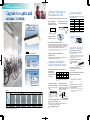
1
Daikin Industries, Ltd.’s products are manufactured for export to numerous countries throughout the
world. Daikin Industries, Ltd. does not have control over which products are exported to and used in a
particular country. Prior to purchase, please therefore confirm with your local authorised importer,
distributor and/or retailer whether this product conforms to the applicable standards, and is suitable for
use, in the region where the product will be used. This statement does not purport to exclude, restrict
or modify the application of any local legislation.
Warning
PCSAU0773
Ask a qualified installer or contractor to install this product. Do not try to install the product yourself.
Improper installation can result in water or refrigerant leakage, electrical shock, fire or explosion.
Use only those parts and accessories supplied or specified by Daikin. Ask a qualified installer or
contractor to install those parts and accessories. Use of unauthorised parts and accessories or
improper installation of parts and accessories can result in water or refrigerant leakage, electrical
shock, fire or explosion.
Read the User's Manual carefully before using this product. The User's Manual provides important
safety instructions and warnings. Be sure to follow these instructions and warnings.
If you have any enquiries, please contact your local importer, distributor and/or retailer.
Cautions on product corrosion
1. Air conditioners should not be installed in areas where corrosive gases, such as acid gas or alkaline gas, are produced.
2. If the outdoor unit is to be installed close to the sea shore, direct exposure to the sea breeze should be avoided. If you need to install
the outdoor unit close to the sea shore, contact your local distributor.
JMI-0107
JQA-1452
Daikin Australia
Pty Limited (ISO 9001)
QEC 23256 31 May 2006
About ISO 9001
ISO 9001 is a plant certification system
defined by the International Organization
for Standardization (ISO) relating to
quality assurance. ISO 9001 certification
covers quality assurance aspects related
to the “design, development,
manufacture, installation, and
supplementary service” of products
manufactured at the plant.
Daikin Australia
Pty Limited (ISO 14001)
CEM20437 13 November 2006
About ISO 14001
ISO 14001 is the standard defined by the
International Organization for Standardization
(ISO) relating to environmental management
systems. Our group has been acknowledged
by an internationally accredited compliance
organisation as having an appropriate
programme of environmental protection
procedures and activities to meet the
requirements of ISO 14001.
Dealer
Head Office:
Umeda Center Bldg., 2-4-12, Nakazaki-Nishi,
Kita-ku, Osaka, 530-8323 Japan
Tokyo Office:
JR Shinagawa East Bldg., 2-18-1, Konan,
Minato-ku, Tokyo, 108-0075 Japan
http://www.daikin.com/global_ac/
c All rights reserved
Specifications, designs and other content appearing in this brochure are current as of September 2007 but subject to change without notice.
ROUND FLOW
NEW
0°
6
3
l
Ful w!!
o
airfl
AIR CONDITIONING SYSTEM
COOLING ONLY [50Hz ]
HEAT PUMP [50Hz ]
Economy and comfort are essential to
store and office air conditioning.
Wide selection with
the inverter series
Our varied lineup meets customer needs when it
comes to functions and indoor unit types.
Enhanced Comfort with
Daikin Inverter
Energy savings with
high-efficiency inverter
New, compact
outdoor unit
Comfortable air conditioning is achieved through variable output control made possible by the inverter, which continually
maintains the set temperature while detecting load, which varies with time of day and number of room occupants.
The outdoor unit is equipped with a reluctance compressor that utilizes the latest technology. It brings out the
full energy-saving potential of the inverter, which controls power used in accordance with load variation.
The outdoor unit is easy to install in stores
and offices where space is limited.
Product Line-up
Series
CEILING MOUNTED
CASSETTE TYPE
Round Flow
25
He a t Pu mp
35
Co o lin g only
50
60
71
100
125
NEW
140
NEW
ROUND FLOW
Page 5
Indoor unit
Heat pump
Outdoor unit
FCQ71KVEA
FCQ100KVEA
FCQ125KVEA
FCQ140KVEA
RZQ71FV4A
RZQ100KV4A
RZQ125KV4A
RZQ160KV4A
COMPACT MULTI FLOW
CEILING MOUNTED
CASSETTE TYPE
Page 9
Indoor unit
Outdoor unit
Heat pump
Cooling only
FFQ25B8V1B
FFQ35B8V1B
FFQ50B8V1B
FFQ60B8V1B
RXS25EAVMA
RKS25EVMA
RXS35EAVMA
RKS35EVMA
RXS50FAVMA
RKS50FVMA
RXS60FVMA
RKS60FVMA
NEW
NEW
CEILING SUSPENDED TYPE
Page 11
Indoor unit
Outdoor unit
Heat pump
Cooling only
FHQ35BVV1B
FHQ50BVV1B
FHQ60BVV1B
FHQ71BVV1B
FHQ100BVV1B
FHQ125BVV1B
RXS35EAVMA
RKS35EVMA
RXS50FAVMA
RKS50FVMA
RXS60FVMA
RKS60FVMA
RZQ71FV4A
RZQ100KV4A
RZQ125KV4A
WALL MOUNTED TYPE
Page 13
FAQ100BVV1B
Indoor unit
Outdoor unit
RZQ100FV4A
Heat pump
CEILING MOUNTED
BUILT-IN TYPE
Page 15
Indoor unit
Outdoor unit
Heat pump
FBQ50BV1A
FBQ60BV1A
FBQ71BV1A
RXS50FAVMA
RXS60FVMA
RXS71FVMA
CEILING MOUNTED
SLIM DUCT TYPE
Page 16
Indoor unit
Outdoor unit
Heat pump
FDXS25CVMA
FDXS35CVMA
FDXS50CVMA
FDXS60CVMA
RXS25EAVMA
RXS35EAVMA
RXS50FAVMA
RXS60FVMA
NEW
Heat pump
Cooling only
RXS25EAVMA
RKS25EVMA
RXS35EAVMA
RKS35EVMA
RXS50FAVMA
RKS50FVMA
RXS60FVMA
RKS60FVMA
RXS71FVMA
O U T D O O R
1
RZQ71FV4A
RZQ100FV4A
RZQ100KV4A
NEW
RZQ125KV4A
NEW
Page 17
RZQ160KV4A
U N I T
2
Round Flow cassette
NEW
Compact
Comfortable airflow
Compact and lightweight
Full 360˚ airflow with improved
temperature distribution.
Reduced installation work thanks to light, compact
outdoor unit.
ROUND FLOW
Reduced by175 mm
Comparison of outdoor units
Conventional
4-way flow type
Round-Flow type
Conventional
NEW
(RZQ100P-160P)
(RZQ100K-160K)
Height
NEW
100/125/160
1,170
mm
1,170 mm
98 kg
1,345 mm
Weight
125 kg
Reduced
by
27 kg
RZQ100P-160P
Energy saving
Greater comfort
Improved energy saving
Optimised Efficiency.
3.40
3.70
3.32
FCQ100KVEA
Non-inverter type air conditioners must be switched on
and off repeatedly, causing large fluctuations
of the room temperature.
Current
Time
Current
Time
Inverter power control
Non-inverter type air conditioner
2
Heating
Heating
1
3
Rated4
Night Quiet Mode
RZQ71F
48
47
RZQ100F
50
49
RZQ100K
49
45
RZQ125K
50
45
RZQ160K
50
46
Running current
Small temp.
difference
FCQ140KVEA
Sound level (dB(A))
Starting current
Inverter
Set temp
FCQ125KVEA
Note :
1
Rated cooling capacities are based on the following conditions: Indoor temp.,
27°CDB, 19.0°CWB; outdoor temp. 35°CDB Equiv. refrigeration piping, 7.5 m
(horizontal).
2
Rated heating capacities are based on the following conditions: Indoor temp.,
20°CDB, outdoor temp., 7°CDB, 6°CWB. Equiv. refrigeration piping, 7.5 m
(horizontal)
Quiet operation
Running
current
Temp
COP is equal to capacity (kW) divided by power consumption (kW),
and the larger the COP value, the higher the energy efficiency,
enabling cooling and heating with less electricity and increasing the
energy saving performance.
Nighttime quiet operation function
Non-inverter
Cooling operation
Cooling
1
Soft starter is
unnecessary, making
electrical installation
work much simpler.
What is COP (Coefficient of Performance)
2
2
Heating
1
2
Inverter performs variable control of frequency,
which determines air conditioner’s power
performance.
3.33
2.83
3
Enhanced comfort with Inverter
At startup, full power is used to achieve the set temperature
quickly. Then, the capacity is adjusted according to the outdoor
temperature changes and subtle indoor load changes to
achieve fine capacity control resulting in a more stable room
temperature.
3.66
1
4
Cooling
Comfortable
Cools a room
in less time
Complies with MEPS
COP
Cooling
4-way flow leaves areas
that cannot be covered.
Full 360° airflow
delivery ensures uniform
airflow distribution.
RZQ100K-160K
Time
At startup, inverter raises frequency smoothly,
eliminating the starting current spike.
Note : 3Anechoic chamber conversion value, measured according to JIS parameters and criteria. During operation these values are somewhat higher owing to ambient conditions.
4
Value when cooling. Value will differ when heating.
3
4
CEILING MOUNTED CASSETTE TYPE
Round Flow
Avoids ununiform temperature and uncomfort caused by drafts.
NEW
Comfort enhanced by new airflow!
Heat pump
FCQ71K/100K/125K/140K
Full 360° airflow
Air movement is gentle with Round Flow
With uniform temperature
distribution
Enhanced Comfort
ROUND FLOW
Full 360° airflow
can maintain
comfort even if air
discharge speed is
lower.
Airflow
distribution
Creates uniform
comfort throughout
the space
Greater comfort
Improved energy saving
If you raise the set temperature by 1 to 1.5°C in cooling (and lower in heating),
and velocity is decreased by 25%, You still obtain the same feeling temperature and comfort.
Option
Easily adapts to the installation space.
Accessory required for indoor unit
Wired LCD remote controller
with weekly schedule timer
Because air flows out of corner outlets, comfort is more widely spread than before.
Typical flow patterns
There are a total of 23 flow patterns.
BRC1D61
All-round flow
3-way flow
(E.g., installed in
middle of ceiling)
(E.g., installed
near a wall)
L-shaped
2-way flow
Note: Remote controller cable not
included. Cables must be
procured locally.
Opposite
2-way flow
Wireless LCD remote controller
A signal receiver must be added to the indoor unit.
Heat pump
BRC7F632F
(E.g., installed in
a corner)
(E.g., installed in
a long room)
4-way flow also possible.
Note: Whatever the discharge direction, the same type of panel is used. If installing for other than all-round flow, an air discharge outlet sealing member (option) must be used to
close each unused outlet.
Signal receiver unit
(Installed type)
Grime prevention and bactericidal coating: Cleanly performance improved.
Wireless remote controller and signal
receiver unit are sold as a set.
External panels are treated with a new coating that
Treated
Untreated
repels dirt.
surface
surface
Features
Heat pump
*1Applicable when wired remote controller is used
5
*1
• • •
•
Others
PE fin
Fresh air intake kit
Ultra long-life filter
High-efficiency filter
Option
Interlock control
Central remote control
Auto-cooling/heating
change-over
Control by 2 remote
controllers
Control by 1 remote
controller
External command
control
Self-diagnosis function
Auto-restart
Control features
Emergency operation
Low gas pressure
detection
Ceiling soiling prevention
Filter sign
Long-life filter
Work & Servicing
Drain water lift-up
mechanism
Pre charged for
up to 30 m
Mould-resistant treatment
for filter
Timer selector
Year-round cooling
applicable
Hot start
High ceiling application
• • • • • •
Two selectable
thermo-sensors
Programme "Dry"
Switchable fan speed
Draft prevention function
Swing pattern selection
Auto swing
Model
Mould
prevention
Comfort
Feature
• • • • • • • • • • • • • • • • • • •
To prevent dirt sticking to the
external panels, they have
been coated with a new
surface treatment.
Resists
soiling
Grimy
surface
• Condition after exposure
to the smoke of 600
cigarettes in 1 m3
enclosed space.
New bactericidal treatment
for drain pan
Non-flocking horizontal louvres
Filter has anti-mould and
bactericidal treatment
Anti bacterial treatment, that includes
silver ions is used which may assist in
preventing the growth of microorganisms
that cause smells and clogging.
Dew does not easily form on and dirt
does not cling to non-flocking louvres.
Less cleaning is needed because
minimal dirt is attracted.
Prevents mould and microorganisms
growing out of the dust and moisture
that adheres to the filters.
6
CEILING MOUNTED CASSETTE TYPE
Unified square panels
Compact body and quiet operation
mm
Indoor unit
High
Low
71K
35
43
44
44
28
32
34
36
100K
95
0m
125K
Same for
all models
m
140K
Optimal comfort and convenience
assured by air discharge modes
Note: Air direction is set to the standard position when the unit is shipped from the factory.
The position can be changed from the remote controller.
Blow direction
Standard setting
Setting to prevent soiling of ceiling*
Desired
situation
Standard position to
prevent draft.
Recommended for shops with
light colored ceilings that
must be kept spotless.
Auto-swing
Blow direction
can be set to
5 levels
Note : Anechoic chamber
conversion value, measured
according to JIS parameters
and criteria. During
operation these values are
somewhat higher owing to
ambient conditions.
Quick and easy to install
Auto-swing between
15° and 60°
Auto-swing between
25° and 60°
Settable to 5 different
levels between 25° and 60°
Settable to 5 different
levels between 15° and 60°
At heating startup and thermo OFF, air discharge
is automatically set to a near horizontal 25˚ or 30˚
to prevent direct exposure to cool air drafts.
The last discharge direction is saved in memory
and automatically set the next time the unit is
turned ON.
Auto blow
direction control
*Closing of the corner discharge outlets is recommended.
Suitable for high ceilings
Even in spaces with high ceilings, a comfortable airflow is carried down to
the floor level.
Criteria for ceiling height and number of air discharge outlets
256 mm *1
265 mm *2
Easy height adjustment
Each corner of the unit has an Adjuster Pocket that
lets you easily adjust the unit's suspended height.
Note: If the wireless remote control option is installed, a light receptor
unit is housed in one of the adjuster pockets.
All models suspended without lift
Installed in
any direction
Since the orientation of
the intake grill can be
adjusted after installing,
the direction of the intake
grill lines can be unified
when multiple units
are installed.
Number of blow outlets used
Standard
Ceiling
High ceiling
height
High ceiling
71K
100K–140K
All round 4-way 3-way 2-way
blow
blow
blow
blow
All round 4-way 3-way 2-way
blow
blow
blow
blow
2.7 m 3.1 m 3.0 m 3.5 m
3.0 m 3.4 m 3.3 m 3.8 m
3.5 m 4.0 m 3.5 m -
3.2 m 3.4 m 3.6 m 4.2 m
3.6 m 3.9 m 4.0 m 4.2 m
4.2 m 4.5 m 4.2 m -
Note: Factory settings are for standard ceiling height and all-round blow.
High ceiling settings (1) and (2) are set with the remote controller.
Two selectable temperature-sensors
Both indoor unit and wired remote controller (option) contain temperaturesensors. Temperature sensing can be set at the unit or, to further improve
comfort level, closer to the target area at the wired remote control. This
feature must be set during commissioning by the technicians.
*Temperature-sensor on indoor unit must be used when the air conditioner is controlled from another room.
**Wireless remote controller does not have a temperature-sensor.
Hot start (after defrost)
Uncomfortable cold air draft is avoided when heating operation starts or
when switching to heat after defrosting.
Switchable fan speed: High/Low
High setting provides maximum reach while low
setting minimizes drafts.
The condition of the drain pan and
drain water can be checked by
removing the drain plug and
intake grille.
Drain pump is equipped as standard
accessory with 850 mm lift.
the
open ille!
t
s
u
r
J
eg
intak
Drain plug
With ultra-long-life filters (option ), maintenance is not required in normal shops or offices
for up to four years.
Just 256 mm high. Can be installed
in tight ceiling spaces (71K)
*1 298 mm high with 100K–140K
*2 303 mm high with 100K–140K
Draft prevention
(In heating mode)
Easier to maintain
dB(A)
Panels are the same size as the FCQ71-140K.
Maintain a neat appearance
where multiple units are installed.
950
Round Flow
Options required for specific operating environments
Ultra-long-life filter
Panel spacer
Even in smoky environments where
the air conditioning is on most of
the time, the ultra long-life filter only
has to be changed once a year.
Use when only minimal space is available between drop
ceilings and ceiling slabs.
Smoky atmosphere: annual filter change
*For dust concentration of 0.3 mg/m3 (Requires separately sold Air Cleaner.)
1 year (Approx. 5,000 hr) 15 hr/day x 28 day/month x 12 month/year
40mm
Ordinary store or office: filter change every 4 years
Panel spacer
*For dust concentration of 0.15 mg/m3
4 years (Approx. 10,000 hr) 8 hr/day x 25 day/month x 4 years
Note: Some ceiling constructions may hinder installation.
Contact your Daikin Dealer before installing your unit.
High-efficiency filter
Available in two types: 65% and 90% colorimetry.
Sealing member of air discharge outlet
Fresh air intake kit
Using this kit, a
duct can be fitted
to increase the
intake of outdoor
air.
Outside
Sealing members block air discharge openings not used in 2way or 3-way blow.
Branch duct (direct-connection round duct)
A round duct can be attached without the need for a chamber.
Note: *Connecting ducts, insect nets, fire dampers, air filters, and other
parts should, as required, be procured locally.
**Outside Air fan interlocked with air conditioning unit is necessary.
Optional PCB(KRP1C63)is required for interlocking.
***It is recommended that the volume of outdoor air introduced
through the kit is limited to 10% of the maximum airflow rate of the
indoor unit. Introducing higher quantities will increase the
operating noise and may also influence temperature sending.
A flanged port for direct connection of a round duct is
provided. An existing branch duct chamber can also be fitted
(square slit hole).
The units can be installed in the following different ways.
Chamber type
(without T-joint pipe and fan)
Chamber type
(with T-joint pipe and without fan)
KDDP55K160
850 mm
175 mm
KDDP55K160K
Flexible duct
(procured locally)
Flexible duct
T-joint pipe
(procured locally)
T-joint pipe
Direct installation type
KDDP55X160
Transparent drain socket
Because the drain socket is
transparent, after the drain piping
has been installed, it is easy to
check if the drain come out
through the socket.
Easier connection with the centralised
control system
Suction
chamber
Intake duct
Connection (procured locally)
chamber
(duct length: 4 m max.)
Suction
chamber
Intake duct
Connection (procured locally)
chamber
(duct length: 4 m max.)
Duct flange
(with insulation
material)
Intake duct
(procured locally)
Note: Use of options will increase operating noise.
Timer selector
Operation starts when the preset time of the ON timer elapses and stops
when the preset time of the OFF timer elapses.
7
8
COMPACT MULTI FLOW
CEILING MOUNTED
CASSETTE TYPE
Compact
Comfortable
Sized to fit inside 600mm wide
ceiling grids
Designed for low draft
performance"
0°
Horizontal Blow
0°
575 mm
575 mm
Heat pump / Cooling only
286
FFQ25B8 / 35B8 / 50B8 / 60B8
Less draft
can be felt
ation
Decor is also
l
e
pan act.
comp
mm
Consistent comfort throughout
Auto-swing operation
distributes conditioned air
more evenly.
700 mm
Air blow angle can be
adjusted in accordance with
room conditions.
AUTO-SWING
5 direction
700 mm
Fits without the
need to cut T-bar
grid
Standard
setting
Ceiling panel
T bar
600 mm
Draft
prevention
setting
(Set on site)
The switch box is built in to the
unit, so maintenance is possible
by simply removing the grill. An
inspection opening is not
required even for modules other
than 600 x 600.
Option
Setting to
prevent
soiling of
ceiling
(Set on site)
Quiet operation has been achieved by a
compact body and newly developed spiral hub
cover that reduces the airflow resistance inside the
indoor unit.
*1Applicable when wired remote controller is used
9
•
•
Central remote control
External command
control
Control by 1 remote
controller
Control by 2 remote
controllers
Auto-cooling/heating
change-over
Self-diagnosis function
Emergency operation
Auto-restart
Filter sign
•
•
Long-life filter
•
•
Pre charged for
up to 10 m
• • • • • • •
• • • • •
• • • • • • • • • • • • •
Drain water lift-up
mechanism
Mould-resistant treatment
for filter
Timer selector
Year-round cooling
applicable
• •
• • •
Low
25B8
29.5
32
36
41
24.5
25
27
32
50B8
PE fin
*1
Indoor unit
High
35B8
Fresh air intake kit
*1
Hot start
Two selectable
thermo-sensors
Programme "Dry"
Switchable fan speed
Draft prevention function
Swing pattern selection
Auto swing
• • • • •
• • • • •
Option Others
Interlock control
Cooling only
Heat pump
Note: Operation noise increases
when using 2-way or 3-way
blow.
Two selectable temperature-sensors
Features
Model
4 pattern
Note: For 3-way or 2-way blow installation, the sealing
member for air discharge outlet (option) must
be used to close off the unused outlet(s).
dB(A)
Control features
Settable to 5 different levels
between 25° and 60°
Blow direction can be
selected according to
installation.
" " denotes piping direction.
Drain piping
"
" denotes sealing member for air discharge
outlet (option) .
Spiral hub cover
Work & Servicing
60°
2 pattern
BRC7E530W7
BRC7E531W7
Wireless remote controller and signal
receiver unit are sold as a set.
Comfort
25°
Auto-swing
between 25° and 60°
Settable to 5 different levels
between 0° and 35°
2-way blow
Signal receiver unit
(Installed type)
Feature
60°
35°
3-way blow
A signal receiver must be added to the indoor unit.
Mould
prevention
25°
1 pattern
Quiet, small-diameter fan
Wireless LCD remote controller
Cooling only
Auto-swing
between 0° and 35°
Note: This angle above is provided as a guide. It may differ depending on the installation site.
Quiet
Note: Remote controller cable not
included. Cables must be
procured locally.
Settable to 5 different levels
between 0° and 60°
0°
35°
4-way blow
BRC1D61
60°
0°
Multi-Flow System
Wired LCD remote controller
with weekly schedule timer
Heat pump
Auto-swing
between 0° and 60°
60°
600 mm
Accessory required for indoor unit
0°
0°
60B8
Note : Anechoic chamber conversion value, measured according to JIS
parameters and criteria. During operation these values are somewhat higher
owing to ambient conditions.
Both indoor unit and wired remote controller (option) contain temperaturesensors. Temperature sensing can be set at the unit or, to further improve
comfort level, closer to the target area at the wired remote control.
This feature must be set during commissioning by the technicians.
*Temperature-sensor on indoor unit must be used when the air conditioner is controlled from another room.
**Wireless remote controller does not have a temperature-sensor.
Hot start (after defrost)
Uncomfortable cold air draft is avoided when heating operation starts
or when switching to heat after defrosting.
Switchable fan speed: High/Low
High setting provides maximum reach while low setting minimizes drafts.
Drain pump is equipped
as standard accessory
with 750 mm lift.
750 mm
10
CEILING SUSPENDED TYPE
Diffuses comfortable air
throughout the room
Quiet operation
Auto-swing (up&down) brings comfort to the room.
Wide air discharge
openings produce a
spreading 100° airflow
Heat pump
FHQ35BV/ 50BV/ 60BV/ 71BV
100BV NEW / 125BV NEW
Air is blown up to 50° in
the downward direction.
50°
Two selectable temperature-sensors
*Temperature-sensor on indoor unit must be used when the air conditioner is controlled from another room.
**Wireless remote controller does not have a temperature-sensor.
Option
Accessory required for indoor unit
Switchable fan speed: High/Middle/Low
Dehumidification is micro processor controlled to prevent abrupt and
uncomfortable changes in air temperature.
Installation flexibility for
greater freedom of design
BRC1D61
Note: Remote controller cable not
included. Cables must be
procured locally.
Uniform height and depth. Compact design for
(mm)
small-capacity
Indoor unit 35BV/50BV 60BV/71BV 100BV 125BV
models to meet
Height
195
tighter dimensional
Width
960
1,160
1,400
1,590
constraints.
Depth
680
Wireless LCD remote controller
A signal receiver must be added to the indoor unit.
BRC7EA63W
BRC7EA66
Weight of all models reduced (down 10% compared
with previous models). Transfer and installation work is
less arduous.
Signal receiver unit (Installed type)
Wireless remote controller and signal
receiver unit are sold as a set.
*2
11
Drain pump kit (option)
can be easily incorporated
The unit fits more snugly into tight
spaces.
Drain pipe connection can be done
inside the unit. refrigerant and drain
pipe outlets are at the same
opening.
*3
*3
• •
• •
*3
Central remote control
External command
control
Control by 1 remote
controller
Control by 2 remote
controllers
or more
Auto-cooling/heating
change-over
Self-diagnosis function
Emergency operation
1,160 mm
30 mm
•
•
Easier to maintain
Long-life filter lasts about half
year * maintenance not required
Two time settings (2500 hrs and 1250 hrs) are available to match the
installation environment. Maintenance time warning is displayed on
the remote controller (filter sign).
Non-dew flap without bristles
Absence of bristles minimizes
clinging dirt and simplifies
cleaning.
Non-dew flap
Easy-clean, flat surfaces
It is easy to wipe dirt off the flat side and lower
surfaces of the unit.
For all maintenance tasks, access is
from below. Work is easier.
Improved-oil resistant
grille
Oil-resistant plastic is used for the air discharge
grille. This improves durability in restaurants and
other similar environments.
Note: Intended for use in salons, dining rooms, and ordinary sales
floors, this specification is not suitable for kitchens or other
harsh environments.
600 mm
or more
*Water used in the test-run can now be drained from the
air discharge opening rather than from the side as was
formerly the case.
• • •
• • • • •
• • • • • • • • •
Auto-restart
Low gas pressure
detection
Filter sign
Long-life filter
Pre charged for
up to 30 m
Drain water lift-up
mechanism
Mould-proofing
drain pan
Mould-resistant treatment
for filter
Timer selector
Year-round cooling
applicable
Others
30 mm
• • • • •
• • • • • •
*1Installable on max. 3.5 m high ceiling
*2Applicable when wired remote controller is used
*3Applicable to RZQ71FV4A RZQ100, 125KV4A outdoor units
Control features
PE fin
*2
Hot start
Two selectable
thermo-sensors
High ceiling
application *1
Programme "Dry"
Switchable fan speed
Draft prevention function
• • • • •
• • • • •
Work & Servicing
Interlock control
Cooling only
Heat pump
Auto swing
Model
Less need for edge space,
more freedom of installation
For 71BV indoor unit
Features
New quiet
stream fan
* For dust concentration of 0.15 mg/m3
Programme "Dry"
Wired LCD remote controller
with weekly schedule timer
125BV
Note : Anechoic chamber conversion value, measured according to JIS
parameters and criteria. During operation these values are somewhat higher
owing to ambient conditions.
Turbulent flow Straightening
is produced
vane
Both indoor unit and wired remote controller (option) contain temperaturesensors. Temperature sensing can be set at the unit or, to further improve
comfort level, closer to the target area at the wired remote control. This
feature must be set during commissioning by the technicians.
Mould
prevention
32
33
33
35
37
39
50BV
Uses quiet stream fan and other quiet
technologies.
Can be installed on
ceilings 3.5 m high
Comfort
Low
37
38
39
39
42
44
71BV
100°
Feature
High
35BV
100BV
Cooling only
Cooling only
Indoor unit
60BV
FHQ35BV/ 50BV/ 60BV
Heat pump
Sound operation has been reduced on the exposed
ceiling suspended type unit.
dB(A)
Drain pump kit
(built inside main unit)
All wiring and internal servicing done from below the unit
Pipes more easily rigged, too
Plastic panels are used to conceal piping holes. Holes can be easily
punched out without requiring special tools.
Low gas pressure detection
12
WALL MOUNTED TYPE
Comfortable
Improved air discharge modes ensure comfortable
air distribution across the entire room
Auto-swing
5-level blow direction setting
10°
10°
Auto-blow direction control
Heat pump
FA Q 100BV
Auto-swing
from 10° to 70°
70°
Gettable to 5
different levels
between 10° to 70°
10°
70°
Last blow direction is
saved in memory and
automatically set
70°
the next time the unit is
turned ON.
(factory setting is 10° for cooling
and 70° for heating.)
Comfort even on the far side of the room
To carry air to the far side of long
rooms, extra-high air blow adds
10% more fan speed the "high"
setting. Air discharge strength is
selected from the remote
controller.
Two selectable temperature-sensors
Both indoor unit and wired remote controller (option) contain temperaturesensors. Temperature sensing can be set at the unit or, to further improve
comfort level, closer to the target area at the wired remote control.
This feature must be set during commissioning by the technicians.
Option
Accessory required for indoor unit
*Temperature-sensor on indoor unit must be used when the air conditioner is controlled from another room.
**Wireless remote controller does not have a temperature-sensor.
Wired LCD remote controller
with weekly schedule timer
Switchable fan speed: High/Low
Programme "Dry"
BRC1D61
Dehumidification is micro processor controlled to prevent abrupt and
uncomfortable changes in air temperature.
Note: Remote controller cable not
included. Cables must be
procured locally.
Easier to install and service
Wireless LCD remote controller
Maintenance possible from the front of the unit
A signal receiver must be added to the indoor unit.
All maintenance tasks can be carried out via front access. During service
work, attachment and detachment of parts is easier.
BRC7C610W
Low gas pressure detection
Insufficient gas charging is normally hard to detect. During postinstallation trials and regular inspection procedures, the refrigerant level
is monitored by computer to ensure proper gas pressure.
Signal receiver unit (Installed type)
Wireless remote controller and signal
receiver unit are sold as a set.
Features
Others
Central remote control
External command
control
Control by 1 remote
controller
Control by 2 remote
controllers
Auto-cooling/heating
change-over
Self-diagnosis function
Emergency operation
Low gas pressure
detection
Mould-resistant
treatment for filter
Year-round cooling
applicable
Control features
Auto-restart
Filter sign
Pre charged for
up to 30 m
•
Mould-proofing
drain pan
• • • • • • • • • • • • • • • • •
Timer selector
PE fin
*1
Hot start
Two selectable
thermo-sensors
High fan speed mode
Programme "Dry"
Switchable fan speed
Draft prevention function
• • • • •
Work & Servicing
Interlock control
Heat pump
Auto swing
Model
Mould
prevention
Comfort
Feature
*1Applicable when wired remote controller is used
13
14
CEILING MOUNTED BUILT-IN TYPE
CEILING MOUNTED SLIM DUCT TYPE
Option
Heat pump
Heat pump
Accessory required for indoor unit
FB Q 50B V / 60B V / 71B V
F DXS2 5 /3 5 /5 0 /6 0 CVMA
Wired LCD remote controller
with weekly schedule timer
BRC1D61
Note: Remote controller cable not
included. Cables must be
procured locally.
Wireless LCD remote controller
A signal receiver must be added to the indoor unit.
BRC4C62
Heat pump
FBQ50BV1A
Signal receiver unit
(Separate type)
Note: Refer to Engineering data for airflow and External
static pressure characteristics.
Wireless remote controller and signal
receiver unit are sold as a set.
Compact
Smooth Finish
Compact design of built-in type helps blend with interior
decor.
The only visible sign of these unobtrusive units is their discharge grilles.
They fit completely inside the ceiling to maintain the original decor of a
room. Each unit comes with its own wireless remote controller.
Height reduced to allow installation in confined spaces.
Comfortable
Work & Servicing
Flexibly adapts to shop interiors
To cope with the challenges of L-shaped or U-shaped spaces, it
is possible to install the air discharge unit away from the main unit.
At the same time, different types of architectural space can be
kept comfortable.
Slim Profile
The height of the unit is a mere 300 mm. It can be
installed in a narrow
ceiling space.
(when access panel is
used.)
The new series adds a 2.5 kW model. All units share the same low height of
just 200 mm. This means it is now possible to install a unit inside a shallow
ceiling cavity with a height of just 240 mm.
300 mm
Access panel
L-shaped room
U-shaped room
Provided with condensate drain pump, waking drain
piping easier in
250 mm
awkward
spaces.
Long room
Quiet Operation
Indoor Unit Quiet Operation provides a low sound level of 31 dB and
Outdoor Unit Quiet Operation provides a low sound level of 47* dB for new
FDXS25C.
dB(A)
Quiet operation
Indoor unit
High
Low
50B
33
34
34
29
30
30
60B
71B
Access panel
* During cooling operation
Features
15
•
•
•
•
•
Heat pump
•
•
•
•
•
•
•
Others
PE fin
•
Automatic cool/heat
change -over
•
Auto-restart
•
Self-diagnosis function
Auto-cooling/heating
change-over
•
Control features
Pre charged for
up to 10 m
Auto-restart
•
Model
Work & Servicing
Hot start
Self-diagnosis function
•
Comfort
Feature
Programme "Dry"
Filter sign
•
PE fin
Pre charged for
up to 10 m
•
Interlock control
Timer selector
•
Central remote
control
Year-round cooling
applicable
•
External command
control
Hot start
•
Control by 1 remote
controller
Programme "Dry"
Heat pump
Others
Control features
Switchable fan speed
Model
Work & Servicing
Control by 2 remote
controllers
Comfort
Feature
Switchable fan speed
Features
•
16
OUTDOOR UNIT
Technology
A collection of cutting-edge technologies
acheives efficient and quiet operation.
The high efficiency compressor to
achieve a high COP
The final word in
inverter technology
1
NEW
NEW
NEW
RZQ100KV4A
RZQ125KV4A
RZQ160KV4A
Easy installation and maintenance
Complies with MEPS
Pre charged for up to 30 metres
Designed for lightness, carry in is easy
If refrigerant piping length does not exceed
30 m, there is no need for on-site gas
charging.
Succeeds in trimming 27 kg off weight of
previous equipment
Energy regulations are met due to
increased operation efficiency.
4-direction piping affords
more freedom of layout
Allowed refrigerant piping length
and height difference
Pre charged1
Max. length
Max. level
difference
71F
30 m
(Equivalent length 70m)
50 m
30 m
100F
30 m
(Equivalent length 70m)
50 m
30 m
75 m
30 m
75 m
30 m
75 m
30 m
100K
30 m
125K
30 m
(Equivalent length 90m)
160K
30 m
(Equivalent length 90m)
(Equivalent length 90m)
Separation
available
Facilitates pump down
(Refrigerant recovery function)
Note : 1Additional refrigerant charging is required if the
refrigerant pipe is longer than the length.
Easy centralised installation
with the module oriented
design
Depth of 71F, 100F, 100K-160K are
standardised as 320 mm. Horizontal
continuous mounting is available.
Suction
320 mm
The outer panel for the piping connection
part of the front, right side and backside
can be removed
and is easier for
post-installation
piping work.
71F
100F
100K
125K
160K
900 mm
900 mm
900 mm
900 mm
900 mm
Discharge
Space saving
A pump-down switch is provided to make it
easier to collect refrigerant if the unit is to
be moved or layout modified.
Low gas level detection function
Effective gas monitoring reduces the labor
required for operation, maintenance, and
repairs.
Operation range
Suited for year-round cooling
applications
Cooling is efficient even in winter when
indoor temperatures are higher than those
outside, such as in underground public
spaces or offices with many computers.
Wide operation range
Reduced installation work thanks to light,
compact outdoor unit.
(Applicable to RZQ100K–160K outdoor units)
40
46˚C
30
20
Cooling
10
0
16˚C
-5˚C
DB
-10
WB
Heating
-15˚C
WB
-20
Outdoor temp
(CDB)
17
2
Reluctance
DC motor
1
4
RZQ100KV4A
RZQ125KV4A
RZQ160KV4A
Use of neodymium magnets in the motor
enables efficient generation of high torque,
reducing the size of the compressor.
Safety
>> Smooth sine wave DC inverter
Reinforcing wire fittings
(option) are available
Fittings can be mounted on the four
locations, right/ left on front and back side
of the outdoor unit.
Ferrite magnet
As the bottom frame is
subject to corrosion,
corrosion-proof galvarium
steel plate is adopted to
enhance the durability.
Non-treated fin
Aluminium
PE fin
Hydrophilic film
Aluminium
Corrosion resistant
acrylic resin
Demand Control Function
Sine wave DC inverter
Neodymium magnet
Durability
Heat exchange fins provided
with anti-corrosion treatment
Use of an optimised sine wave
smoothes motor rotation, further
improving operating efficiency.
Neodymium magnets are
much more powerful than
the commonly used ferrite
magnets.
>> Stronger materials
>> Optimal refrigerant configuration
The strength of the casing has been increased
by boosting the internal dome pressure.
Changes to the shape of the spiral and volume
ratio result in optimal refrigerant layout.
RZQ71FV4A/100FV4A
RZQ100KV4A/125KV4A/160KV4A
>> Swing compressor
Energy savings is
realised, eliminating
the friction and the
leakage of
refrigerant gas.
2
Swing bushing
Refrigerant gas
Sucked gas is compressed in the
scrolling part before the heated motor,
so that the machine compress
the non-expanded gas, resulting Discharge
high efficiency compression.
Piston by incorporated
blade and roller.
With the beat
blade edge
These two features work to significantly reduce
noise. Guides are added to the bell mouth intake
to reduce turbulence in the airflow generated by
fan suction. The Aero Spiral Fan features fan
blades with the bent blade edges, further reducing
turbulence.
3
DC fan motor structure
Scroll section
Motor section
Without the beat
blade edge
Escaping eddies are sucked in by
the bent blade edges, reducing
overall turbulence.
DC fan motor
DC motor efficiency
Efficiency improved in all areas compared to
conventional AC motors, especially at low
speeds.
The maximum capacity is maintained
within a set level of power consumption,
which makes it possible to keep comfort
and effective demand control.
Suction
>> The structural scroll
Smooth Air Inlet Bell Mouth and Aero Spiral Fan
Limitation
DB
3
>> Powerful magnets
Construction
50
Compact design with reduced height
By introducing high pressure oil, the
reactive force from the fixed scroll is added
to the internal force, thereby reducing
thrust losses. This results in improved
efficiency and suppressed sound levels.
Power
consumption
(Applicable to RZQ100K–160K outdoor units)
High thrust mechanism
(comparison with a conventional AC motor)
100
Efficiency (%)
RZQ71FV4A
RZQ100FV4A
75 m piping length
Reluctance DC Scroll Compressor
Overheating losses are reduced by pressurising the area
around the motor, energy saving performance in conjunction
with other features.
80
DC motor
60
Approx.
20%
increase
40 Approx.
AC motor
40%
20 increase
0
200 300
400 500
600
700 800
900 1000
Note: Data are based on
studies conducted under
controlled conditions at
a Daikin laboratory.
Motor speed (rpm)
8:00
12:00
16:00
* Required for KRP58M51 (Option)
20:00 Time
4
Super Aero Grille
Refined ventilation mechanism enables further reduction in required fan
power.
Outdoor temp
(CWB)
18
LCD REMOTE CONTROLLER
Necessary optional accessory
Easy-to-read LCD remote controller allows
various system control configurations and
can control multiple indoor units.
Simple system provides a diverse assortment of control modes.
LCD REMOTE CONTROLLER
Control pattern
Control by 1
remote controller
Wired remote controller
(Basic system)
Non-polar, double-core
(max. wiring length 500 m)
Remote controller options are shown on the page introducing each indoor unit model.
Wired LCD remote controller with weekly schedule timer
Remote control is equipped with weekly timer function.
24-hour clock function (1-hour backup for
power failures)
Programming function for each day of week.
Scheduling possible of start/stop and
temperature limit (5 settings/day)
Programming can be enabled or disabled.
Copy function for programmed schedules.
BRC1D61
LCD wireless remote controller
The wireless remote controller is
supplied in a set with a signal
receiver.
Shape of signal receiver unit
differs according to the indoor
unit.
Signal receiver unit
(For ceiling mounted
cassette type)
Wireless remote
controller
Note: The signal receiver unit shown in the
photograph is for mounting inside
the decoration panel of the ceiling
mounted cassette type.
Indoor units applicable for the remote controller
Signal receiver unit is contained inside decoration panel or indoor unit
Heat pump
Cooling only
BRC7F632F
—
COMPACT MULTI FLOW TYPE
BRC7E530W7
BRC7E531W
CEILING SUSPENDED TYPE
BRC7EA63W
BRC7EA66
WALL MOUNTED TYPE
BRC7C610W
—
BRC4C62
—
Standard accessory
—
CEILING MOUNTED CASSETTE TYPE
CEILING MOUNTED BUILT-IN TYPE
CEILING MOUNTED SLIM DUCT TYPE
Control by 2
remote controllers
Signal receiver unit installed
on indoor unit
Control by 1 wireless remote
controller and 1 wired remote
controller (See note 1)
For control from 2
locations such as in
room and control room,
exits, etc.
Signal receiver unit installed
on indoor unit
Connects 2 wired
remote controllers
(Applies to wired remote controllers)
Enables temperature detection closer to target
area for improved comfort. (When using remote
control from another room, thermo-sensor in
indoor unit's air inlet must be selected.)
Non-polar, double-core connection
specifications simplify wiring
Non-polar, double-core remote controller wire
prevents wiring mistakes. Signal receiver unit (or
decoration panel) of wireless type is also easy to
connect.
Group control
All initial settings can be set from the remote
controller. After interior construction is complete,
ceiling mounted cassette type can be remotely
set without having to use stepladder access for
manual setting.
For simultaneous
control of up to 16
indoor units.
Automatic address setting function
Automatic address setting function
Signal receiver unit installed
on 1 indoor unit
Control by
external command
Operation and
surveillance is carried out
using the contact signal
from the operation control
box in the building
surveillance (security)
room.
Optional wiring adaptor for
electrical appendices is necessary
Optional wiring adaptor for
electrical appendices is necessary
Central remote controller (option)
Facilitates maintenance and repair
Light receptor mounted type
BRC7F632F
Wired remote controller has
built-in thermo-sensor
Wireless remote controller
Centralised remote
control
Central remote controller (option)
Centralised control of
up to 64 indoor units
from remote location
up to 1 kilometer away.
Optional SkyAir series interface
adaptor required.1
Optional SkyAir series interface
adaptor required.1
Setting contents: High ceiling use, air direction, filter type, address
for centralised control (group control address is set automatically).
Remote controller is equipped with model name
and failure display functions. This facilitates
service in the unlikely event of a malfunction.
SkyAir shares common control with
HRV (heat reclaim ventilation) and
the other Daikin air-conditioning
units, thus simplifying interlocking
operations.
Easily adaptable to large-scale, high-function,
centralised remote control systems.
Installing and connecting control wiring between
SkyAir and other Daikin air-conditioning
equipment is easy.
Optional adaptor for external commands or
remote control of external equipment has been
standardised to one type.
HRV
Link by remote
controller group control.
Interlock control
with HRV
HRV
Can be operated simultaneously
or independently by remote controller
(set by ventilation mode)
Can be operated simultaneously
by remote controller
(set by ventilation mode)
Central remote controller (option)
Zone link control by
centralised control.
Central remote controller (option)
HRV
HRV
HRV for indoor units within a zone are operated by interlocking
Can also be operated independently by remote controller.
HRV for indoor units within a zone are operated
by interlocking
Note: When a wireless remote controller is used, remote control by two remote controllers is not possible.
1
The ceiling mounted cassette type come standard with an interface adaptor for SkyAir series (DTA112BA51).
Easily adaptable to large-scale, high-function, centralised remote control system.
Central remote controller
DCS302CA61 (Option)
Unified on/off controller
Schedule timer
DCS301BA61 (Option)
DST301BA61 (Option)
DCS601C51 (Option)
LCD panel shows operating status in letters, numbers, and motion.
Airflow / swing display
Preset temperature / operation mode display
Programming time display
Self-diagnosis function
Displays auto-swing operating status and setting position of air discharge angle.
Displays preset room temperature and operating status (fan, dry, cool).
Operation start and stop time can be set for individual timers up to 72 hours. The liquid crystal display also shows
when it is time to clean the filter, when changeover is under centralised control, and ventilation/cleaning.
Centralised control, with setting as
simple as it is with a standard
remote controller, of up to 64 groups
(1,024 indoor units) is possible.
Centralised control of on/off by
group or all at once for up to 256
indoor units.
Unified control of weekly schedule
for up to 1,024 indoor units.
Schedule timer sets on/off time in 1 minute units
to be executed twice a day for a week at a time.
With its high functionality, the full
colour “all-in-one” graphic controller
facilitates management of SkyAir
System in a variety of ways.
*Please refer to the page 29 for the details.
Monitors operating status within the system covering 40 items, and displays a message to indicate as soon as a malfunction occurs.
Interface adaptor for SkyAir series
DTA112BA51 (Option)
Enables centralised control via connection
to a high-speed, DIII-NET communication
system, adopted for the Daikin VRV system.
The interface adaptor for the Skyair series is
optional except for the ceiling mounted cassette
type.
Necessary for interface adaptor for SkyAir series with the
central remote control units shown at above.
19
20
Abundance of functions that provide comfortable
air-conditioning in stores and offices.
Note: Some features only available on selected models. See model pages for full list of features applicable to each unit.
Comfort
Auto-swing
Delivers comfortable airconditioning to all areas,
near to and far from the airconditioner.
Work and Servicing
Drain water lift-up mechanism
Steeper gradient ensures more
efficient condensate drainage.
High-lift is especially useful for
long lengths of drain piping.
High-ceiling application
Air discharge direction angle can
be set (fixed setting)
Note: Some features only available on selected models. See model pages for full list of features applicable to each unit.
Delivers air-conditioning comfort all the way down to the floor
in air-conditioning zones with high ceilings.
*When using a wired remote controller the sign is displayed in the LCD. When using a
wireless remote controller the filter sign lamp illuminates on the signal receiver unit.
Low gas pressure detection
Pre charged for up to 30 metres
*available on all models.
If refrigerant piping length does not exceed 30 m, there is no
need for on-site gas charging.
*Applicable to RZQ71F/100F, outdoor units
(RXS25E/35E, RXS50F/60F RKS25E/35E, RKS50F/60F outdoor units): 10 m
Swing pattern selection
(standard, ceiling soiling prevention)
You can freely set 2 airflow positions by remote controller.
(1) Airflow range in
standard position
Note:When units are installed on high ceilings, depending on the model, various restrictions
concerning maximum height, air discharge direction, and choice of options may apply.
Thermo-sensors are included in the indoor unit and optional
wired remote controller. Temperature detection closer to
target area is possible to further
increase the comfort level.
Maintenance is not required for one year (two years when a
ceiling mounted cassette type is used).
Ceiling soiling prevention function
Daikin's innovative air discharge mechanism keeps airflow
away from the ceiling. Ceiling cleaning is less frequently
required.
Draft prevention function (heating)
To prevent cold air drafts, automatically adjusts airflow to
horizontal vector when heating initially starts or when the
thermostat turns off.
Hot start (after defrost)
(Horizontal air discharge)
Switchable fan speed
Use the thermo-sensor in the indoor
unit when controlling air conditioning
from another room.
Note: Wireless remote controllers have no
thermo-sensor.
*available on all models.
High setting provides maximum reach while low setting
minimizes drafts.
Programme "Dry" with a humidity sensor
*available on all models.
Dehumidification is computer controlled to prevent abrupt and
uncomfortable changes in air temperature. Useful for reducing
discomforting humidity without uncomfortable cooling of the
room.
High fan speed mode
*available on all models.
Uncomfortable cold avoided is not discharged when heating
operation starts or when switching to heat after defrosting.
Efficient cooling even in winter when indoor temperatures are
higher than those outside, such as in underground public
spaces or offices with many computers.
Timer selector
Operation starts when the preset time of the ON timer elapses
and stops when the preset time of the OFF timer elapses.
Auto-restart
*available on all models.
If there is a power outage while the equipment is operating,
operations will restart in the same mode as before the power
cut when electricity is restored.
Auto cool/heat change-over (Heat pump only)
*available on all models.
Detects difference in preset temperature and actual room
temperature and automatically switches to cooling or heating
accordingly.
Control by 2 remote controllers
Using 2 remote controllers you can operate the equipment
locally or from a remote location.
The operating parameters of indoor and outdoor units, and
sensor data at critical locations throughout the system, are
constantly monitored using a microcomputer. To facilitate
quick response in the event of a malfunction, a message
appears on the LCD of the remote controller and an LED on
the unit illuminates.
External command control
Operation and surveillance is carried out using the contact
signal from the operation control box in the building
surveillance (security) room.
Central remote control
Optional central remote controller enables centralised control
of up to 1024 indoor units (64 groups) from up to 1 kilometer
away.
Interlock control
Enables interlocking control with external equipment such as
heat reclaim ventilation (HRV).
Control by 1 remote controller
You can turn up to 16 indoor units on/off with a single remote
controller. (When using connected indoor units, the settings
must all be the same and on/off will be simultaneous.)
Mould-proofing drain pan
Mould-proofing maintains hygiene by preventing growth in
highly humid conditions.
Options
High-efficiency filter unit
Others
*available on all models.
To achieve increased durability by improved resistance to salt corrosion and atmospheric pollution, coated PE fins (with special acryl
pretreatment) are used for the heat exchanger of the outdoor unit.
In high corrosive areas, regular maintenance needs to be carried out.
21
*available on all models.
Note: When a wireless remote controller is used, remote control by two remote controllers is
not possible.
Mould prevention
PE fin
Self diagnosis function
*Required for KRP58M51 (Option)
Year-round cooling applicable
Applicable for wall mounted type
Sanitary filter has mould-resistant treatment.
If there is a malfunction elsewhere in the system, the fan or
compressor can still be operated.
Control features
You can increase fan speed approximately 10% higher than
the "high" setting.
Mould-resistant treatment for filter
Insufficient gas charging is normally hard to detect. During
post-installation trials and regular inspection procedures, the
refrigerant level is monitored by computer to ensure proper
gas pressure. Reliability is assured and maintenance and
inspection can be carried out more quickly.
Emergency operation
Long-life filter
Two selectable thermo-sensors
(2) Airflow range in ceiling
soiling prevention
position
Filter sign
The filter sign warns you when it is time to clean the filter.
Two types are available: 65% and 90% colorimetry.
Ultra long-life filter
Requires no maintenance for about 4 years* (10,000h) in
stores and offices.
*For dust concentration of 0.15 mg/m3
Fresh-air intake kit
You can provide air-conditioning with fresh air from outside.
Convenient for places where a ventilation fan cannot be
installed.
Note: *Connecting ducts, insect nets, fire dampers, air filters, and other parts
should, as required, be procured locally.
**Outside Air fan interlocked with air conditioning unit is necessary. Optional
PCB(KRP1C63)is required for interlocking.
***It is recommended that the volume of outdoor air introduced through the kit
is limited to 10% of the maximum airflow rate of the indoor unit. Introducing
higher quantities will increase the operating noise and may also influence
temperature sending.
22
SPECIFICATIONS
Heat pump
CEILING MOUNTED CASSETTE TYPE
Model
Name
100
125
140
Indoor unit
FCQ71KVEA
FCQ100KVEA
FCQ125KVEA
FCQ140KVEA
Outdoor unit
RZQ71FV4A
RZQ100KV4A
RZQ125KV4A
RZQ160KV4A
Power supply
Cooling capacity1
Rated (Min. - Max.)
Heating capacity2
Rated (Min. - Max.)
Power consumption
Indoor
unit
Outdoor
unit
CEILING SUSPENDED TYPE
71
1 Phase, 240 V, 50 Hz
kW
kW
Cooling1
Heating2
Unit
Colour
Decoration panel
Air flow rate (H/L)
Sound level (H/L)3
Sound power (H/L)4
Dimensions Unit
(HXWXD)
Decoration panel
Machine
Unit
weight
Decoration panel
Cooling
Certified
Operation range Heating
Colour
Type
Compressor
Motor output
Refrigerant charge (R-410A)
Sound level
Cooling/Heating3
Night quiet mode
Sound power 4
Dimensions (HXWXD)
Machine weight
Cooling
Certified
Operation range Heating
Liquid (Flare)
Piping
connections
Gas (Flare)
Drain
Indoor unit
Outdoor unit
Max. interunit piping length
Max. installation level difference
Heat insulation
kW
kW
7.1
(3.3-8.0)
8.0
(3.5-9.0)
2.05
2.10
10.0
(5.0-11.2)
11.2
(5.1-12.8)
2.94
3.03
12.5
(5.7-14.0)
14.0
(6.0-16.2)
3.77
3.83
14.0
(6.2-15.4)
16.0
(6.2-18.0)
4.95
4.80
550/375
33/22.5
44/34
61/52
298X840X840
50X950X950
24
5.5
550/375
33/22.5
44/36
61/54
298X840X840
50X950X950
24
5.5
---------Fresh white
/s
m3/min
dB(A)
dB(A)
mm
mm
kg
kg
°CWB
°CDB
kW
kg
dB(A)
dB(A)
dB(A)
mm
kg
°CDB
°CWB
mm
mm
mm
mm
m
m
350/225
21/13.5
35/28
53/46
256X840X840
50X950X950
21
5.5
533/333
32/20
43/32
60/50
298X840X840
50X950X950
24
5.5
14 to 25
15 to 27
Ivory white
Hermetically sealed
swing type
1.8
2.8
(Charged for 30 m)
48/50
47
66
770X900X320
65
Hermetically sealed scroll type
1.9
3.7
(Charged for 30 m)
49/51
45
65
1,170X900X320
98
o/ 9.5
o/ 15.9
I.D o/ 25XO.D o/ 32
o/ 26.0 (Hole)
35
50
60
71
100
125
Indoor unit
FHQ35BVV1B
FHQ50BVV1B
FHQ60BVV1B
FHQ71BVV1B
FHQ100BVV1B
FHQ125BVV1B
Outdoor unit
RXS35EAVMA
RXS50FAVMA
RXS60FVMA
RZQ71FV4A
RZQ100KV4A
RZQ125KV4A
7.1
(3.3-8.0)
8.0
(3.5-9.0)
2.58
2.84
1 Phase, 240 V, 50 Hz
10.0
(5.0-11.2)
11.2
(5.1-12.8)
3.26
3.77
12.1
(5.7-14.0)
14.0
(6.0-16.2)
4.40
4.55
Power supply
Cooling capacity1
Rated (Min. - Max.)
Heating capacity2
Rated (Min. - Max.)
Power consumption
Indoor
unit
Outdoor
unit
kW
kW
Cooling1
Heating2
Colour
Air flow rate (H/L)
Sound level (H/L)3
Sound power (H/L)4
Dimensions (HXWXD)
Machine weight
Cooling
Certified
Operation range Heating
Colour
Type
Compressor
Motor output
Refrigerant charge (R-410A)
Sound level
2.4
3.7
(Charged for 30 m)
50/52
45
–
1,170X900X320
98
3.1
3.7
(Charged for 30 m)
50/52
46
–
1,170X900X320
98
o/ 9.5
o/ 15.9
I.D o/ 25XO.D o/ 32
o/ 26.0 (Hole)
75 (Equivalent length 90)
o/ 9.5
o/ 15.9
I.D o/ 25XO.D o/ 32
o/ 26.0 (Hole)
-5 to 46
-15 to 16
o/ 9.5
o/ 15.9
I.D o/ 25XO.D o/ 32
o/ 26.0 (Hole)
50 (Equivalent length 70)
Model
Name
Cooling/Heating3
Night quiet mode
Sound power Cooling/Heating4
Dimensions (HXWXD)
Machine weight
Cooling
Certified
Operation range Heating
Piping
Liquid (Flare)
connections
Gas (Flare)
Drain
Indoor unit
Outdoor unit
Max. interunit piping length
Max. installation level difference
Heat insulation
kW
kW
1 Phase, 220–240 V, 50 Hz
5.0
5.7
3.4
(1.7-5.6)
(1.7-6.0)
(1.2-3.7)
6.0
7.2
4.0
(1.7-7.0)
(1.7-8.0)
(1.2-5.0)
1.72 (0.44-1.98)
2.00 (0.44-2.19)
1.05 (0.3-1.23)
2.04 (0.4-2.4)
2.49 (0.4-2.78)
1.11 (0.29-1.61)
White
/s
m3/min
dB(A)
dB(A)
mm
kg
°CWB
°CDB
kW
kg
dB(A)
dB(A)
dB(A)
mm
kg
°CDB
°CWB
mm
mm
mm
mm
m
m
216/167
13/10
37/32
–/53
195X960X680
24
0.6
1.0
(Charged for 10 m)
47/48
–
62/63
550X765X285
32
10 to 46
-10 to 20
o/ 6.4
o/ 9.5
VP20 (I.Do/ 20XO.Do/ 26)
o/ 18.0 (Hole)
20
15
216/167
13/10
38/33
–/54
195X960X680
25
14 to 28
10 to 30
283/233
17/14
39/35
55/51
195X1,160X680
27
283/216
17/13
39/33
–/55
195X1,160X680
27
400/333
24/20
42/37
58/53
195X1,400X680
32
14 to 25
15 to 27
500/416
30/25
44/39
60/55
195X1,590X680
35
Ivory white
Hermetically sealed swing type
Hermetically sealed scroll type
1.1
1.8
1.9
2.4
1.1
2.8
3.7
3.7
1.5
1.5
(Charged for 10 m) (Charged for 10 m) (Charged for 30 m) (Charged for 30 m) (Charged for 30 m)
47/48
49/49
48/50
49/51
50/52
–
–
47
45
45
61/62
63/63
65
–
66
735X825X300
735X825X300
1,170X900X320
1,170X900X320
770X900X320
48
48
65
98
98
-5 to 46
10 to 46
-15 to 16
-15 to 18
o/ 6.4
o/ 6.4
o/ 9.5
o/ 9.5
o/ 9.5
o/ 12.7
o/ 12.7
o/ 15.9
o/ 15.9
o/ 15.9
VP20 (I.Do/ 20XO.Do/ 26) VP20 (I.Do/ 20XO.Do/ 26) VP20 (I.Do/ 20XO.Do/ 26) VP20 (I.Do/ 20XO.Do/ 26) VP20 (I.Do/ 20XO.Do/ 26)
o/ 18.0 (Hole)
o/ 18.0 (Hole)
o/ 26.0 (Hole)
o/ 26.0 (Hole)
o/ 26.0 (Hole)
30
30
50 (equivalent length 70)
75 (equivalent length 90)
20
20
30
Both liquid and gas piping
30
Both liquid and gas piping
WALL MOUNTED TYPE
100
COMPACT MULTI FLOW CEILING MOUNTED CASSETTE TYPE
25
Model
Name
Power consumption
Indoor
unit
60
FFQ25B8V1B
FFQ35B8V1B
FFQ50B8V1B
FFQ60B8V1B
RXS25EAVMA
RXS35EAVMA
RXS50FAVMA
RXS60FVMA
kW
Cooling1
Heating2
Unit
Colour
Decoration panel
Air flow rate (H)
(H/L)3
Outdoor
unit
50
Outdoor unit
kW
Sound level
Sound power4
Dimensions
(HXWXD)
Machine
weight
Certified
Operation range
Colour
Compressor
35
Indoor unit
Power supply
Cooling capacity1
Rated (Min. - Max.)
Heating capacity2
Rated (Min. - Max.)
Unit
Decoration panel
Unit
Decoration panel
Cooling
Heating
Type
Motor output
Refrigerant charge (R-410A)
Sound level
Cooling/Heating3
Sound power Cooling/Heating4
Dimensions (HXWXD)
Machine weight
Cooling
Certified
Operation range Heating
Piping
Liquid (Flare)
connections
Gas (Flare)
Drain
Indoor unit
Outdoor unit
Max. interunit piping length
Max. installation level difference
Heat insulation
kW
kW
1 Phase, 220–240 V, 50 Hz
3.4
4.7
(1.2-3.7)
(1.7-5.6)
4.0
5.5
(1.2-5.0)
(1.7-7.0)
1.10
1.62
1.20
1.88
---------White
167/108
200/133
10/6.5
12/8
36/27
32/25
49
53
286X575X575
286X575X575
55X700X700
55X700X700
17.5
17.5
2.7
2.7
14 to 28
10 to 30
Ivory white
Hermetically sealed swing type
0.6
1.1
1.5 (Charged for 10 m)
1.0 (Charged for 10 m)
47/48
47/48
62/63
61/62
550X765X285
735X825X300
32
48
2.5
(1.2-3.0)
3.2
(1.2-4.5)
0.73
0.92
/s
m3/min
dB(A)
dB(A)
mm
mm
kg
kg
°CWB
°CDB
150/108
9/6.5
29.5/24.5
46.5
286X575X575
55X700X700
17.5
2.7
kW
kg
dB(A)
dB(A)
mm
kg
°CDB
°CWB
mm
mm
mm
mm
m
m
0.6
1.0 (Charged for 10 m)
47/48
62/63
550X765X285
32
10 to 46
-10 to 20
5.8
(1.7-6.0)
7.0
(1.7-8.0)
2.065
2.49
250/167
15/10
41/32
58
286X575X575
55X700X700
17.5
2.7
1.1
1.5 (Charged for 10 m)
49/49
63/63
735X825X300
48
10 to 46
-15 to 18
o/ 6.4
o/ 9.5
VP20 (I.D o/ 20XO.D o/ 26)
o/ 18.0 (Hole)
o/ 6.4
o/ 9.5
VP20 (I.D o/ 20XO.D o/ 26)
o/ 18.0 (Hole)
Indoor unit
Model
Name
o/ 6.4
o/ 12.7
VP20 (I.D o/ 20XO.D o/ 26)
o/ 18.0 (Hole)
o/ 6.4
o/ 12.7
VP20 (I.D o/ 20XO.D o/ 26)
o/ 18.0 (Hole)
20
15
30
20
Outdoor unit
Power supply
Cooling capacity1
Rated (Min. - Max.)
Heating capacity2
Rated (Min. - Max.)
Power consumption
Indoor
unit
FAQ100BVV1B
RZQ100FV4A
kW
kW
Cooling1
Heating2
Colour
Air flow rate (H/L)
Sound level (H/L)3
Sound power (H/L)4
Dimensions (HXWXD)
Machine weight
Cooling
Certified
Operation range Heating
Colour
Outdoor
Type
Compressor
unit
Motor output
Refrigerant charge (R-410A)
Sound level
Cooling/Heating3
Night quiet mode
Sound power Cooling/Heating4
Dimensions (HXWXD)
Machine weight
Cooling
Certified
Operation range Heating
Piping
Liquid (Flare)
connections
Gas (Flare)
Drain
Indoor unit
Outdoor unit
Max. interunit piping length
Max. installation level difference
Heat insulation
kW
kW
/s
m3/min
dB(A)
dB(A)
mm
kg
°CWB
°CDB
kW
kg
dB(A)
dB(A)
dB(A)
mm
kg
°CDB
°CWB
mm
mm
mm
mm
m
m
1 Phase, 220–240 V, 50 Hz
9.7
(4.9-11.0)
11.0
(5.5-12.6)
3.53
3.77
White
483/316
23/19
45/41
61/57
360X1,570X200
26
14 to 28
10 to 27
Ivory white
Hermetically sealed swing type
1.8
2.8 (Charged for 30 m)
50/54
49
70/70
770X900X320
65
-5 to 46
-15 to 15.5
o/ 9.5
o/ 15.9
VP20(External Dia, 26/Internal Dia. 20)
o/ 26.0 (Hole)
50 (Equivalent length 70 m)
30
Both liquid and gas piping
Note :
1
Rated cooling capacities are based on the following conditions: Indoor temp., 27°CDB, 19.0°CWB; outdoor temp. 35°CDB Equiv. refrigeration piping, 7.5 m (horizontal).
2
Rated heating capacities are based on the following conditions: Indoor temp., 20°CDB, outdoor temp., 7°CDB, 6°CWB. Equiv. refrigeration piping, 7.5 m (horizontal)
3
Anechoic chamber conversion value, measured according to JIS parameters and criteria. During operation these values are somewhat higher owing to ambient conditions.
4
Numerical values are according to ISO 3741:1999.
23
24
SPECIFICATIONS
Heat pump
Cooling only
CEILING MOUNTED BUILT-IN TYPE
Indoor unit
Model
Name
Outdoor unit
Power supply
Cooling capacity1
Rated (Min. - Max.)
Heating capacity2
Rated (Min. - Max.)
Indoor
unit
Colour
Fan
Air flow rate Cooling
(H/L)
Heating
External static pressure3
(High-Standard-Low)
Sound level4 Cooling (H/L)
Heating (H/L)
Sound power5 Cooling (H/L)
Heating (H/L)
Dimensions (HXWXD)
Machine weight
Cooling
Certified
Operation range
Heating
Colour
Outdoor
Type
Compressor
unit
Motor output
Refrigerant charge (R-410A)
Sound level4 Cooling/Heating
Night quiet mode
Sound power5 Cooling/Heating
Dimensions (HXWXD)
Machine weight
Cooling
Certified
Operation range
Heating
Liquid
Piping
connections
Gas
Indoor unit
Drain
Outdoor unit
Max. interunit piping length
Max. installation level difference
Heat insulation
71
FBQ50BV1A
FBQ60BV1A
FBQ71BV1A
RXS60FVMA
RXS71FVMA
kW
kW
5.0
(1.7-5.6)
6.0
(1.7-7.0)
1.98 (0.44-2.25)
1.93 (0.4-2.52)
/s
m /min
/s
m3/min
216/150
13/9
233/167
14/10
1 Phase, 220–240 V, 50 Hz
5.7
(1.7-7.0)
7.0
(1.7-8.0)
2.23 (0.44-2.83)
2.26 (0.4-0.94)
---------300/216
18/13
316/233
19/14
kW
Power consumption
60
RXS50FAVMA
kW
Cooling
Heating
COMPACT MULTI FLOW CEILING MOUNTED CASSETTE TYPE
50
3
6.7
(2.3-8.0)
8.2
(2.3-10.0)
2.57 (0.57-0.326)
2.67 (0.45-0.385)
88-49-20
88-49-20
88-49-20
33/29
33/29
------------------300X700X800
34
34/30
34/30
------------------300X1000X800
41
kW
kg
dB(A)
dB(A)
dB(A)
mm
kg
°CDB
°CWB
mm
mm
mm
mm
m
m
1.1
1.5 (Charged for 10 m)
47/48
---------61/62
735X825X300
48
34/30
34/30
------------------300X1000X800
41
14 to 28
10 to 30
Ivory white
Hermetically sealed swing type
1.1
1.5 (Charged for 10 m)
49/49
---------63/63
735X825X300
48
10 to 46
-15 to 18
o/ 6.4
o/ 12.7
VP25 (I.D o/ 25XO.D o/ 32)
o/ 18.0
30
20
Both liquid and gas piping
1.92
2.3 (Charged for 10 m)
52/52
47
66/66
770X900X320
71
o/ 6.4
o/ 15.9
o/ 18.0
Note :
1
Rated cooling capacities are based on the following conditions: Suction temp., 27°CDB, 19.0°CWB; outdoor temp. 35°CDB. Equiv. refrigeration piping, 7.5 m (horizontal)
2
Rated heating capacities are based on the following conditions: Suction temp., 20°CDB; outdoor temp., 7°CDB, 6°CWB. Equiv. refrigeration piping, 7.5 m (horizontal)
3
Factory setting is 49Pa.
4
Anechoic chamber conversion value, measured according to JIS parameters and criteria. During operation these values are somewhat higher owing to ambient conditions.
5
Numerical values are according to ISO 3741:1999.
35
FDXS35CVMA
50
FDXS50CVMA
60
FDXS60CVMA
Outdoor unit
RXS25EAVMA
RXS35EAVMA
RXS50FAVMA
RXS60FVMA
Power consumption
Indoor
unit
/s
m3/min
Pa(mmH2O)
158/133
9.5/8
40
dB(A)
dB(A)
mm
kg
°CWB
°CDB
35/31
---------200X900X620
25
kW
kg
dB(A)
dB(A)
mm
kg
°CDB
°CWB
mm
mm
mm
mm
m
m
0.6
1.0 (Charged for 10 m)
47/48
62/63
550X765X285
32
kW
Cooling1
Heating2
Colour
Air flow rate (H/L)
Fan
kW
kW
2.4
(1.2-3.0)
3.2
(1.2-4.5)
0.69 (0.3-0.92)
0.91 (0.29-1.49)
External static pressure
Driving system
Sound level (H/L)3
Sound power (H/L)4
Dimensions (HXWXD)
Machine weight
Cooling
Certified
Operation range Heating
Colour
Outdoor
Type
Compressor
unit
Motor output
Refrigerant charge (R-410A)
Sound level Cooling/Heating3
Sound power Cooling/Heating4
Dimensions (HXWXD)
Machine weight
Cooling
Certified
Operation range Heating
Piping
Liquid (Flare)
connections
Gas (Flare)
Drain
Indoor unit
Outdoor unit
Max. interunit piping length
Max. installation level difference
Heat insulation
FFQ60B8V1B
Outdoor unit
RKS25EVMA
RKS35EVMA
RKS50FVMA
RKS60FVMA
1 Phase, 220–240 V, 50 Hz
3.4
4.7
(1.2-3.7)
(1.7-5.6)
Outdoor
unit
Unit
Decoration panel
Air flow rate (H)
kW
2.5
(1.2-3.0)
kW
0.73
1 Phase, 220–240 V, 50 Hz
3.4
5.0
(1.2-3.8)
(1.7-5.3)
4.0
5.8
(1.2-5.0)
(1.7-6.0)
1.09 (0.3-1.27)
1.65 (0.44-1.93)
1.18 (0.29-1.79)
1.92 (0.4-2.04)
---------167/142
200/167
10/8.5
12/10
40
40
35/31
---------200X900X620
25
6.0
(1.7-6.5)
7.0
(1.7-8.0)
2.13 (0.44-2.49)
2.32 (0.4-3.18)
266/225
16/13.5
40
37/33
---------200X900X620
27
38/34
---------200X1,100X620
30
14 to 28
10 to 30
Ivory white
Hermetically sealed swing type
1.1
0.6
1.5 (Charged for 10 m)
1.0 (Charged for 10 m)
47/48
47/48
62/63
61/62
735X825X300
550X765X285
32
48
10 to 46
-10 to 20
o/ 6.4
o/ 9.5
VP20 (I.D o/ 20XO.D o/ 26)
o/ 18.0
1.1
1.5 (Charged for 10 m)
49/49
63/63
735X825X300
48
10 to 46
-15 to 18
o/ 6.4
o/ 9.5
VP20 (I.D o/ 20XO.D o/ 26)
o/ 18.0
o/ 6.4
o/ 12.7
VP20 (I.D o/ 20XO.D o/ 26)
o/ 18.0
20
15
5.8
(1.7-6.0)
1.62
2.065
200/133
12/8
36/27
53
286X575X575
55X700X700
17.5
2.7
250/167
15/10
41/32
58
286X575X575
55X700X700
17.5
2.7
---------White
/s
m3/min
dB(A)
Sound level (H/L)2
dB(A)
Sound power3
mm
Dimensions Unit
(HXWXD)
mm
Decoration panel
kg
Machine weight Unit
kg
Decoration panel
°CWB
Certified operation range
Colour
Compressor Type
Motor output
kW
Refrigerant charge (R-410A)
kg
Sound level (H/L)2
Sound power3
Dimensions (HXWXD)
Machine weight
Certified operation range
Piping
Liquid (Flare)
connections
Gas (Flare)
Drain
Indoor unit
Outdoor unit
Max. interunit piping length
Max. installation level difference
Heat insulation
1.10
dB(A)
dB(A)
mm
kg
°CDB
mm
mm
mm
mm
m
m
150/108
9/6.5
29.5/24.5
46.5
286X575X575
55X700X700
17.5
2.7
167/108
10/6.5
32/25
49
286X575X575
55X700X700
17.5
2.7
14 to 28
Ivory white
Hermetically sealed swing type
1.1
0.6
1.5
1.0
(Charged for 10 m)
(Charged for 10 m)
0.6
1.0
(Charged for 10 m)
47/44
62
550X765X285
32
47/44
62
550X765X285
32
1.1
1.5
(Charged for 10 m)
47/44
61
735X825X300
48
49/46
63
735X825X300
48
10 to 46
o/ 6.4
o/ 6.4
o/ 12.7
o/ 9.5
VP20 (I.Do/ 20XO.Do/ 26)
VP20 (I.D o/ 20XO.D o/ 26)
o/ 18.0 (Hole)
o/ 18.0 (Hole)
o/ 6.4
o/ 9.5
VP20 (I.Do/ 20XO.Do/ 26)
o/ 18.0 (Hole)
o/ 6.4
o/ 12.7
VP20 (I.D o/ 20XO.D o/ 26)
o/ 18.0 (Hole)
30
20
20
15
Both liquid and gas piping
35
50
60
Indoor unit
FHQ35BVV1B
FHQ50BVV1B
FHQ60BVV1B
Outdoor unit
RKS35EVMA
RKS50FVMA
RKS60FVMA
Power supply
25
50
FDXS25CVMA
kW
60
FFQ50B8V1B
Power consumption
Colour
Indoor
unit
Model
Name
Indoor unit
Power supply
Cooling capacity1
Rated (Min. - Max.)
Heating capacity2
Rated (Min. - Max.)
50
FFQ35B8V1B
CEILING SUSPENDED TYPE
CEILING MOUNTED SLIM DUCT TYPE
Model
Name
35
FFQ25B8V1B
Cooling capacity1
Rated (Min. - Max.)
300/216
18/13
316/233
19/14
Pa
o/ 18.0
25
Indoor unit
Power supply
dB(A)
dB(A)
dB(A)
dB(A)
mm
kg
°CWB
°CDB
o/ 6.4
o/ 12.7
Model
Name
o/ 6.4
o/ 12.7
VP20 (I.D o/ 20XO.D o/ 26)
o/ 18.0
Cooling capacity1
Rated (Min. - Max.)
Power consumption
Colour
Indoor
Air flow rate (H)
unit
Outdoor
unit
Sound level (H/L)2
Sound power3
Dimensions (HXWXD)
Machine weight
Certified operation range
Colour
Compressor Type
Motor output
Refrigerant charge (R-410A)
Sound level (H/L)2
Sound power3
Dimensions (HXWXD)
Machine weight
Certified operation range
Piping
Liquid (Flare)
connections
Gas (Flare)
Drain
Indoor unit
Outdoor unit
Max. interunit piping length
Max. installation level difference
Heat insulation
kW
kW
/s
m3/min
dB(A)
dB(A)
mm
kg
°CWB
kW
kg
dB(A)
dB(A)
mm
kg
°CDB
mm
mm
mm
mm
m
m
3.4
(1.2-3.7)
1.05
216/167
13/10
37/32
53
195X960X680
24
0.6
1.0
(Charged for 10 m)
47/44
62
550X765X285
32
o/ 6.4
o/ 9.5
VP20 (I.Do/ 20XO.Do/ 26)
o/ 18.0 (Hole)
20
15
1 Phase, 220–240 V, 50 Hz
5.0
(1.7-5.6)
1.72
White
216/167
13/10
38/33
54
195X960X680
25
14 to 28
Ivory white
Hermetically sealed swing type
1.1
1.5
(Charged for 10 m)
47/44
61
735X825X300
48
10 to 46
o/ 6.4
o/ 12.7
VP20 (I.Do/ 20XO.D o/ 26)
o/ 18.0 (Hole)
30
20
Both liquid and gas piping
5.7
(1.7-6.0)
2.00
283/216
17/13
39/33
55
195X1,160X680
27
1.1
1.5
(Charged for 10 m)
49/46
63
735X825X300
48
o/ 6.4
o/ 12.7
VP20 (I.D o/ 20XO.D o/ 26)
o/ 18.0 (Hole)
30
20
Note :
1
Rated cooling capacities are based on the following conditions: Indoor temp., 27°CDB, 19.0°CWB; outdoor temp. 35°CDB Equiv. refrigeration piping, 7.5 m (horizontal).
2
Anechoic chamber conversion value, measured according to JIS parameters and criteria. During operation these values are somewhat higher owing to ambient conditions.
3
Numerical values are according to ISO 3741:1999.
30
20
Both liquid and gas piping
Note :
1
Rated cooling capacities are based on the following conditions: Suction temp., 27°CDB, 19.0°CWB; outdoor temp. 35°CDB. Equiv. refrigeration piping, 7.5 m (horizontal).
2
Rated heating capacities are based on the following conditions: Suction temp., 20°CDB; outdoor temp., 7°CDB, 6°CWB. Equiv. refrigeration piping, 5 m (horizontal).
3
Anechoic chamber conversion value, measured according to JIS parameters and criteria. During operation these values are somewhat higher owing to ambient conditions.
4
Numerical values are according to ISO 3741:1999.
25
26
OPTIONS
Indoor unit
CEILING SUSPENDED TYPE
CEILING MOUNTED CASSETTE TYPE
Name of option
Remark
FCQ71KVEA
Decoration panel
Sealing member of air discharge outlet
Panel spacer
Without the T-joint pipe and fan
Fresh air
Chamber
type
intake kit1
With the T-joint pipe, without fan
Direct installation type
Chamber connection kit2
Insulation kit for high humidity
(Colorimetric method 65%)
High-efficiency filter
(Colorimetric method 90%)
Replacement
(Colorimetric method 65%)
high-efficiency filter
(Colorimetric method 90%)
Filter chamber
Long-life filter
Ultra long-life filter
Replacement ultra long-life filter
Branch duct chamber
Wired type3
Remote controller
Wireless type
Central remote controller4
Unified ON/OFF controller4
Schedule timer4
Touch Controller4
Adaptor for wiring5
Group control adaptor5
Installation box for adaptor PCB
KDTP55K80
KAFP556H80
KAFP557H80
KAFP552H80
KAFP553H80
KDJP55H80
Note: 1Refer to page 8 for the details.
2
Required for installing high-efficiency filter or ultra long-life filter at the fresh air intake kit.
3
Wiring for wired remote controller to be procured locally.
Kit name
FCQ100KVEA
FCQ125KVEA
BYCP125K-W1
KDBH55K160F
KDBP55H160FA
KDDP55K160
KDDP55K160K
KDDP55X160
KKSJ55K160
KDTP55K160
KAFP556H160
KAFP557H160
KAFP552H160
KAFP553H160
KDDFP55H160
KAFP551K160
KAFP55H160
KAFP55H160H
KDJP55H160
BRC1D61
BRC7F632F
DCS302CA61
DCS301BA61
DST301BA61
DCS601C51
KRP1C63
KRP4A53
KRP1H98
FCQ140KVEA
Replacement long-life filter
Drain-up kit
L-type piping kit (for upward direction)
Remote controller
Panel spacer1
Name of option
The indoor unit is equipped standardly with the interface for SkyAir series and an option is unnecessary.
5
Installation box for adaptor PCB (KRP1H98) is necessary.
o
o
o
o
o
o
o
o
o
o
x
x
x
o
o
o
o
o
High-humidity
operation kit
High-efficiency
filter2
Ultra-long-life
filter2
x
o
x
o
o
o
o
o
x
o
o
o
o
x
x
x
x
x
Wireless
Fresh air intake kit Fresh air intake kit
remote controller (Chamber type)1,2
(direct mount)
High-humidity
operation kit
High-efficiency
filter2
o3
o
x
o
x
o
x
x
x
x
x
x
x
High-humidity
operation kit
High-efficiency
filter2
Ultra-long-life
filter2
x
x
x
x
x
x
o
o
o
o3
o
o
o
o
o3
o
x
x
x
o
o
o
Ultra-long-life
filter2
o3
o
o
o
x
Branch duct connection
Optional accessory parts
Independently installable optional parts
Branch duct1
1-way branch / unit 3-way blow
(Chamber type)
2-way branch / unit 2-way blow
(Round duct type)
1-way branch / unit 2-way blow
Panel spacer1
Wireless
Fresh air intake kit Fresh air intake kit
remote controller (Chamber type)1,2
(direct mount)
o
x
x
o
o
o
o4
o4
o4
o
o
o
1
In some cases, depending on how the unit is embedded in the ceiling, use of branch ducts and fresh air intake kits may not be possible. Before starting installation work make sure to check
whether or not joint installation is possible. In particular, ensure that the lower fixing position caused by the addition of panel spacers is acceptable.
2
Use a chamber connection kit if two different types of optional chamber are used together. In this case, the fresh air intake kit must be installed in the upper position.
3
It is not possible to use panel spacers in a 2-way blow installation because condensation will form.
4
It is not possible to install a branch duct on the same side to which a fresh air intake kit (direct mount) is installed.
Decoration panel
Remote controller
Wired type1
Wireless type
FFQ25B8V1
Heat pump
Cooling only
wiring2
Adaptor for
Wiring adaptor for electrical appendices2
Remote sensor
Installation box for adaptor PCB
Central remote controller3
Unified ON/OFF controller3
Schedule timer3
Touch Controller3
Interface adaptor for SkyAir series
Replacement long-life filter
Fresh air intake kit
Direct installation type
Sealing member for air discharge outlet
Panel spacer
Note: 1Wiring for wired remote controller to be procured locally.
27
2
Installation box for adaptor PCB (KRP1B101) is necessary.
FFQ35B8V1
FFQ50B8V1
BYFQ60B7W1
BRC1D61
BRC7E530W7
BRC7E531W7
KRP1B57
KRP4A53
KRCS01-1
KRP1B101
DCS302CA61
DCS301BA61
DST301BA61
DCS601C51
DTA112BA51
KAFQ441B60
KDDQ44X60
KDBHQ44B60
KDBQ44B60
3
Wired
Wireless type
Heat pump
Central remote controller2
Unified ON/OFF controller2
Schedule timer2
Touch Controller2
Wiring adaptor for electrical appendices3
Interface adaptor for SkyAir series
Electrical box with earth terminal (3 blocks)
Electrical box with earth terminal (2 blocks)
Note: 1Wiring for wired remote controller to be procured locally.
2
This optional accessory requires DTA112BA51.
3
Installation box (KRP4A93) is necessary for wiring adaptor KRP4A51
CEILING MOUNTED BUILT-IN TYPE
Name of option
Remark
Service access panel
Adaptor for discharge
Remote controller
FBQ50BV1A
KTBJ25K56W
KDAJ25K56
Wired type1
Wireless type
Adaptor for wiring (interlock for fresh air intake fan)
Grope control adapter
Interface adaptor for SkyAir series
Central remote controller2
Unified ON/OFF controller2
Schedule timer2
Touch Controller2
Kit name
FBQ60BV1A
FBQ71BV1A
KTBJ25K80W
KDAJ25K71
BRC1D61
BRC4C62
KRP1BA54
KRP4A51
DTA112BA51
DCS302CA61
DCS301BA61
DST301BA61
DCS601C51
Note: 1Wiring for wired remote controller to be procured locally.
2
This optional accessory requires DTA112BA51.
Name of option
Kit name
Remark
Remote controller
type1
CEILING MOUNTED SLIM DUCT TYPE
COMPACT MULTI FLOW CEILING MOUNTED CASSETTE TYPE
Name of option
KRP4AA52
DTA112BA51
KRP1CA93
KRCS01-1A
EKROROA
KJB311AA
KJB212AA
Kit name
FAQ100BVV1B
BRC1D61
BRC7C610W
DCS302CA61
DCS301BA61
DST301BA61
DCS601C51
KRP4A51
DTA112BA51
KJB311A
KJB212A
Remark
4
Wireless
Fresh air intake kit Fresh air intake kit
remote controller (Chamber type)1,2
(direct mount)
o3
o3
o3
x
o3
Heat pump
Cooling only
FHQ100BVV1B FHQ125BVV1B
KAF501DA112 KAF501DA160
KDU50N125VE
KHFP5MA160
WALL MOUNTED TYPE
3-way blow 2-way blow
Optional accessory parts
Independently installable optional parts
Panel/grille related
Panel spacer1
Operation control related
Wireless remote controller
Auxillary function related
Fresh air intake kit (Chamber type)1,2
Fresh air intake kit (direct mount)
High-humidity operation kit
Filter related
Ultra-long-life filter2
KHFJ5F50
Wired type1
Wireless type
Kit name
FHQ50BVV1B FHQ60BVV1B FHQ71BVV1B
KAFJ501D80
KAF501DA80
KDU50M60VE
KHFJ5F80
BRC1D61
BRC7EA63W
BRC7EA66
DCS302CA61
DCS301BA61
DST301BA61
DCS601C51
KRP1BA54
KRP4A52
DTA112BA51
KRP1C93
-------------------------------------
Note: 1Wiring for wired remote controller to be procured locally.
2
This optional accessory requires DTA112BA51.
3
Installation box for adaptor PCB (KRP1C93) is necessary.
All round blow 4-way blow
o
o
o
x
o
o
Resin net
Central remote
Unified ON/OFF controller2
Schedule timer2
Touch Controller2
Adaptor for wiring
Wiring adaptor for electrical appendices3
Interface adaptor for SkyAir series
Installation box for adaptor PCB
Remote sensor
Connector for forced on, forced off
Electrical box with earth terminal (3 blocks)
Electrical box with earth terminal (2 blocks)
For each blow pattern – all round, 4-way, 3-way, 2-way, branch duct connection – the compatibility of each independently installed option
(shown in the column on the left) to accessory options (listed across the top of each table) is shown in the cells where the relevant row and column intersect.
A circle (o) indicates compatibility, and a cross (x) indicates incompatibility. Any options not shown below are not suitable for independent or accessory installation.
Panel spacer1
FHQ35BVV1B
KAFJ501D56
controller2
Round flow type: List of optional parts required to achieve different blow patterns
Optional accessory parts
Independently installable optional parts
Panel/grille related
Panel spacer1
Operation control related
Wireless remote controller
Auxillary function related
Fresh air intake kit (Chamber type)1,2
Fresh air intake kit (direct mount)
High-humidity operation kit
Filter related
High-efficiency filter2
Ultra-long-life filter2
Remark
Name of option
FFQ60B8V1
Remark
5-room centralized controller1
Adaptor PCB (normal open/normal open pulse contact)2
The remote controller loss prevention with the chain
Interface adaptor for DIII-NET use
Central remote controller3
Unified ON/OFF controller3
Schedule timer3
Touch Controller3
Suction grille
Insulation kit for high humidity
FDXS25CVMA
Kit name
FDXS60CVMA
FDXS35CVMA
FDXS50CVMA
KRC72
KRP413A1S
KRP917A4
KRP928B2S
DCS302CA61
DCS301BA61
DST301BA61
DCS601C51
KDGF19A45
------KDT25N63
KDT25N50
Note: 1Adaptor PCB is also required for each indoor unit.
2
Time clock and other devices ; obtained locally.
3
This optional accessory requires KRP928B2S.
This optional accessory requires DTA112BA51.
28
OPTIONS
DIMENSIONS
Indoor unit
(Unit: mm)
CEILING MOUNTED CASSETTE TYPE
Trouble
reports
Color LCD Touch panel Icon display
Multilingual (English, French, German,
Spanish, Italian, or Chinese)
Mobile Phone
Special
Function 1
D NET Plus Adapter
(option) [DCS601A52]
Indoor Unit
HRV
Number of indoor unit expanded from 64 to 128.
* Limitations apply to some models and functions.
For details please contact your local sales office.
Necessary for optional interface adaptor for SkyAir series (DTA112BA51) with the
Suspension bolt
4-M8~M10
Connection position
of branch duct
(round shape type)
20 C/L
157
350
280
330
4
1
2
35 or less
(Note 4)
Connection position
of branch duct
(round shape type)
256
157
350
A
35 or less
(Note 4)
Connection position
of branch duct
(square-shaped type)
167
160
67
29
95
160
67
95
29
157
350
2 100=200 80
213
25
160
C/L
167
93
C/L
80
20-M4 Prepared hole
55
5
Connection position
of branch duct
(square-shaped type)
20-M4
Prepared hole
157
350
840
81 2x100=200 85
64
124
50
2x100=200 80
25
124
55
[FCQ100-140KVEA]
160
124
109
95
213
[FCQ71KVEA]
3
95
110
124
80
16-M4 Prepared hole
55 Connection position
of branch duct
(square-shaped type)
Connection position
of branch duct
(square-shaped type)
B arrow view
ø1
Connection position
(kn 00
of branch duct
ock
hole
(round shape type)
)
90
Connection position
183
of fresh air intake kit
C
arrow
view
(direct installation type)
Connection position
of branch duct
(round shape type)
Connection position
of fresh air intake kit
(direct installation type)
90
Special
Function 3
840
340
80 2 100=200
B
160
D -NET
55
1500 or more
(required space)
From the floor side 2500 or more
For height installation
Labor saving Overall energy savings
Simplified BMS
• Connection to power consumption meter
when using power proportional
distribution function. (Optional)
160
A
10
RS-232C
Forced OFF
command from
fire alarm
monitoring panel
16-M4 Hole
157
350
Connection position
of branch duct
(square-shaped type)
Connection position
of branch duct
(square-shaped type)
20-M4
Prepared hole
Connection position
85 of branch duct
(round shape type)
2 100=200
160
C/L
[FCQ71KVEA]
130
Pi Port
Trouble reports
850
Adjustable(0~675)
Forced OFF
contact input
Special
Function 3
Yearly schedule
Power proportional distribution* (option)
Auto cool/heat change-over
Temperature Limitation
B arrow view
420
175
29
Simple interlock function
157
350
C
81
93
780(Suspension position)
860~910(Ceiling opening space) (Note 4)
7
A arrow view
Remote monitoring and control
50
40
Special
Function 5
Special
Function 4
Special
Function 2
6
Drain Connection
Side
60
Built-in Ethernet port for connecting to
the Internet or an intranet
Unified ON/OFF
and status
monitoring from
the central
monitoring panel
105
Special
Function 4
Unification
adapter for
computerized
control
[DCS302A52]
42
Sending of e-mail alerts to a specified
address when malfunctions occur (Optional)
PCMCIA
Flash
Memory
150
Special
Function 3
DCS601C51
• CSV output of
power proportional distribution
results (Optional)
D
E
Support for centralized control from else
where., using a PC with a Web browser (Optional)
950
Special
Function 2
95
C
Doubling of number of connectable indoor
unit by adding a D -NET PLUS adapter (Optional)
125
165
Special
Function 1
[FCQ100-140KVEA]
85 Connection position
of branch duct
(round shape type)
16-M4 Hole
95
110
9
Pipe Connection
Side
2x100=200
124
C/L
124
8
81
160
Note 2
[FCQ71KVEA]
860~910(Ceiling opening space) (Note 4)
710(Suspension position)
420
ø1
(kn 00
ock
hole
)
90
B
300
or less
950
80
New communication functions in the user-friendly icon based
multilingual controller simplity centralized control of the system
90
196
C arrow view
Touch Controller.
[FCQ100-140KVEA]
Name of option
Air direction adjustment grille
Drain plug
Name of option
Air direction adjustment grille
Drain plug
29
Remark
One set includes 5 pieces for 5 units
Remark
One set includes 5 pieces for 5 units
RZQ125KV4A
RZQ160KV4A
Kit name
Heat pump
RXS25EVMA
RXS35EVMA
RXS50FVMA
RXS60FVMA
KPW937A4
KPW945A4
KKP937A4
Kit name
Cooling only
RKS25EVMA
RKS35EVMA
RKS50FVMA
RKS60FVMA
KPW937A4
KPW945A4
KKP937A4
60
35 or less
(Note 4)
Connection position
of branch duct
(round shape type)
55
85
27-M4 Prepared hole
256
157
350
A
Required space
200mm or more
1500mm or more
1500mm
or more
5
130
RZQ100FV4A
840
2 100=200
160
42
RZQ71FV4A
150
Name of option
Central drain plug
Wire fixture for preventing overturning
Fixture for preventing overturning
Demand adaptor
Kit name
Heat pump
RZQ100KV4A
KKPJ5F180
K-KYZP15C
KPT-60B160
KRP58M51
105
81
64
50
67
1500 or more 160
(required space)
From the floor side 2500 or more
For height installation
Outdoor unit
95
167
93
29
3 55
35 or less
(Note 4)
Connection position
of branch duct
(square-shaped type)
Notes:
1
Sticking location for manufacture's label
manufacture's label for indoor unit:
Suction grille inner side's electric components box's lid surface
manufacture's label for decoration panel :
Decoration panel's corner decoration cover inner surface
2
In case of using wireless remote controller, this position will be a signal receiver. Refer to the drawing of wireless remote controller
in detail.
3
When the temperature and humidity in the ceiling exceed 30˚C and RH 80% or the fresh air is inducted into the ceiling or the unit
continues 24 hour operation, an additional insulation (thickness 10mm or more of glasswool or polyethylene form) is required.
4
Though the installation is acceptable up to maximum of 910mm square ceiling opening, keep the clearance of 35mm or less
between the indoor unit and the ceiling opening so that
the panel overlap allowance can be ensured.
5
Please do not place the thing been damp and troubled under an indoor unit.
When the case where humidity is 80% or more, and the drain outlet are choked up and the air filter are dirty, dew may fall.
1500mm
or more
200mm
or more
1500mm or more
When the blow-off grille is closing.
The required space is 500mm or more.
When uniting and closing a corner part
(both right and left of the blow-off grille to close),
it is 200mm or more.
A
B
C
D
E
FCQ71KVEA
246 124 124 110 256
FCQ100-140KVEA
288 160 167 160 298
1 Liquid pipe connection
2 Gas pipe connection
3 Drain pipe connection
4 Power-source wiring and a unit wiring connection
5 Connection wiring / remote control wiring connection
6 Air-outlet
7 Suction grille
8 Corner decoration cover
9 Drain hose (accessory)
30
(Unit: mm)
COMPACT MULTI FLOW CEILING MOUNTED CASSETTE TYPE
Piping direction
585–660 (Ceiling opening space)
533 (Suspension position)
320
300 or less
Note)2.
89
8
Pipe connection
side
50 or more
(Required space)
Ceiling
89
B
Outdoor air intake
(Direct connection)
4–M4 Hole
9
4
A
40
50
70
120
120
50
or more
100
210
123
360
A
A
A
A
A
A
53
10
A
(Required space)
1235
120
120
A
Direction for air filter draw out
45
40
50 40
50 30 40 40
295 or more
From the floor side
2500 or more
(180)
2
1500 or more
(Required space)
205
145
183
285
45 or less
Note)4.
45 or less
1
*When the discharge grill is closeout, the
required space is 200mm or more.
180
Ceiling surface
15
1500mm or more*
120
142
62.5
8-5x20 Oval Hole (For wood screw)
5-6x20 Oval Hole (For wood screw)
50 35
575
196
250 or more
Service space
for air filter
2
10
1500mm or more*
5
260
25
60
40
6 6
62.5
For height installation
750
Adjustable(0–545)
74
575
Brand name plate
Note 2.
3
200
1500mm or more*
62.5
55
30
8
320
3
Suspension bolt
4–M8 to M10
7
B arrow view
Required space
1500mm or more*
172
211
1
7
A arrow view
62.5
50 or more
(Required space)
1570
100
150
533 (Suspension position)
700
6
585–660 (Ceiling opening space)
210
Drain connection
side
360
700
WALL MOUNTED TYPE
Approx. 450
Approx. 580
Approx. 600
6
15
DIMENSIONS
5
13- 5 Hole (For wood screw)
2- 12 Hole (For bolt)
4
60
80 Hole
Piping and wiring
intake
Mounting location
Detail A (Mounting hole for installation plate)
1 Liquid pipe connection
2 Gas pipe connection
Notes:
1
Sticking location for manufacture's label
manufacture's label for indoor unit : on the bell mouth inside suction grille
manufacture's label for decoration panel : on the inner frame inside suction grille
2
In case of using wireless remote controller, this position will be a signal receiver.
refer to the drawing of wireless remote controller in detail.
3
When the temperature and humidity in the ceiling exceed 30˚C and RH 80% or the fresh air is inducted into the ceiling or the unit
continues 24 hour operation, an additional insulation (thickness 10mm or more of glasswool or polyethylene form) is required.
4
Though the installation is acceptable up to maximum of 660mm square ceiling opening, keep the clearance of 45mm or less between
the main unit and the ceiling opening so that the panel overlap allowance can be ensured.
3 Drain pipe connection
4 Power supply connection
5 Remote control code and
control wiring connection
6 Air discharge grille
7 Suction grille
8 Drain hose
CEILING SUSPENDED TYPE
H
160
228
(Knock hole)
80
225
275
80
3
2
(Applies to FHQ35-71BV only)
The remote control code is the standard <about 3 m outside the machine> attached.
(0.5 mm2 2 wicks O.D. 5.4)
(It is not attached to VRV.)
7
5
80
105
170
B
F
G
Notes:
1
Location of unit's Name Plate: Fan hosing surface.
2
If the ceiling is not removable, a 300 mm service space
must be kept between the unit and the ceiling.
3
Mount the air filter at the suction side.
(Select its colorimethod (Gravity method) 50 % or more)
57
Service space
300 or more
6-M5 Hole
(Circumference)
5
3
B view
1
195
Suspension bolt
65
25
2
6
45
A
3 65=195
300
275
55
14
4 o/ 45
Brand name plate
(Note.2)
1 Air discharge grille
2 Air suction grille
3 Air filter
4 Gas pipe connection
6
5 Liquid pipe connection
6 Drain pipe connection
7 Earth terminal (inside the electric components box) (M4) (Applies to FHQ35-71BV)
Earth terminal (inside the control box) (M4) (Applies to FHQ100P/125P)
8 Suspension bracket
9 Backward piping and wiring connection opening lid
10 Upward piping and wiring connection opening lid
4
11 Right side pipe connection
12 Left back drain pipe connection
13 Left side drain pipe connection
14 Right side drain pipe connection
15 Hole of wall for taking out in piping back
16 Upward drain pipe connection
17 Upward gas pipe connection
18 Upward liquid pipe connection
440
315
50
67
The Front
Obstacle
Floor side
800
25
60
D
E
30 or more
(Service space)
135 120
B
30 or more
(Service space)
Notes:
1
Location of unit's Name Plate: Bottom of fan housing inside the suction grille.
2
In case of using wireless remote controller, this position will be a signal receiver.
Refer to the drawing of wireless remote controller in detail.
31
11
600
Fresh sir intake position
9
2 65=130
5
Drain pipe connection VP20
(For left piping)
3
125
10
90
155
300 or more
6
(Required space)
55
160 P.C.D.
A view
Position : Hole of wall for taking out in piping back
(View from the front)
195
680
1
150
200
Hanging bolt
4-M8~M10
27
C
40
5
(Required space)
For height installation
From the floor side 2500 or more 155
13
15
100
105
8
A
(Hanging position)
I
J
(Suspension position)
10
150
127
208
65
60
Position slit hole for taking out in piping back
(View from the front)
250
260
50
300
245
215
150
135
1550 1590
8
A
B
300
Service space
Note)2
FHQ125BVV1B
115 60
1360 1400
65
1120 1160
FHQ100BVV1B
5
135 (Required space)
FHQ71BVV1B
630
(Suspension position)
145
145 60
135
960
1120 1160
40
920
FHQ60BVV1B
9
12
85
102
160
185
192 36
FHQ50BVV1B
7
170
105
90
18 17 16 142 58
210
B
960
Front grille
Air filter
Discharge outlet
Gas piping connection
Gas piping connection
Drain piping connection
Earth terminal (M4) (inside cover)
Slit hole for right side piping connection
Slit hole for left side piping connection
CEILING MOUNTED BUILT-IN TYPE
(Hanging
position)
A
920
FHQ35BVV1B
1
2
3
4
5
6
7
8
9
Notes:
1
Location of general rated name plate Right side plate outside surface
2
In case of using wireless remote controller,
this position will be a signal receiver. Refer to the drawing of wireless remote controller in detail.
4
46
1
2
3
4
5
6
7
8
9
10
Liquid pipe connection
Gas pipe connection
Drain pipe connection
Interunit wiring port
Power wiring port
Drain hole
Discharge flange
suction flange
Switch box
Inspection hole
A
B
C
FBQ50BV1A
556
533
4X120=480
E
460
F
3X150=450
G
485
H
6X65=390
FBQ60BV1A/71BV1A
856
833
6X120=720 1000 760
5X150=750
785
11X65=715 12X65=780 1050
D
700
I
7X65=455
J
750
32
DIMENSIONS
(Unit: mm)
OUTDOOR UNIT // RXS25EAVMA, RXS35EAVMA, RKS25EVMA, RKS35EVMA
CEILING MOUNTED SLIM DUCT TYPE
620
Liquid pipe connection
Gas pipe connection
Socket for drain
Drain hose (Standard accessory)
Control box
Infrared receiver unit connection
Power supply connection
Suspension bracket
Air filter (Standard accessory)
Protection net
Allow view A
13
12
63
765
Outdoor air thermistor
10
20
50
9
130
100
90
80
196
E
880
F
860
FDXS60CVMA
1100 26- 4.7 hole 10XP100=1000 1140 1080 1060 6XP150=900 9XP100=900
FDXS25CVMA/35CVMA/50CVMA
I
J
K
N
L
M
780 800 820 900 20-M5 holes 7XP100=700
980 1000 1020 1100 24-M5 holes 9XP100=900
FDXS60CVMA
G
Gas stop valve
(o/ 9.5 CuT)
H
4XP150=600 7XP100=700
O
22
In case of removing
stop valve cover
Wall height on air outlet side
=less than 1200
Minimum space for air passage
A
B
C
900 22- 4.7 hole 8XP100=800
In case of bottom-suction
D
Brand name label
FDXS25CVMA/35CVMA/50CVMA
940
Service
port
9
In case of back suction
Notes:
1
In case of back-suction, mount chamber cover to bottom side of the unit.
In case of bottom-suction, mount chamber cover to back side of the unit.
2
Location of unit's Name Plate: control box cover.
3
Mount the air filter at the suction side.
(Select its colorimethod (Gravity method) 50 % or more)
It can not be equipped with air filter (accessory) when connecting duct to suction side.
6
H
I
J
K
N
O
P
Q
P
Q
50
200
180
160
100
10
150
100
90
80
50
50
780 800 820
980 1000 1020
50
100
24-M5 Holes
(All around)
7
105
4
5
300
3
150
330
30
100
18-M4 Holes
(All around)
165
100
160
180
170
100
Wiring
inlet
150
10
Liquid
stop valve
(o/ 6.4CuT)
550
M
(All around)
50
20
10
1
23
200
170
153
80
8
Brand name label
285
Name
plate
47
90
130 63
105.5
490
Handle
Inspection door
(ceiling opening)
2
4 –Holes for anchor bolts
(M8 or M10)
574
29.5
1
2
3
4
5
6
7
8
9
10
311
L
300
Service space
E
F
G
12.5
21
57.5
240 or more
500
(Suspension bolt pitch)
Suspension bolt
4-M8 M10
Ceiling
A
60
620
(All around) B
C
D
(Suspension bolt pitch)
8
Drain outlet
(I. D o/ 15.9 hose for connection)
400 or more
(In case of
bottom suction)
20 or more
20 or more
300 or more
(Service space)
A
OUTDOOR UNIT // RXS50FAVMA, RXS60FVMA, RKS50FVMA, RKS60FVMA
825
78
325
124
580
36
2
330
300
25
350
10
Drain outlet
(I.D. o/ 15.9 hose for connection)
4 –Holes for anchor bolts
(M8 or M10)
In case of removing
stop valve cover
Name plate
Outdoor air temperature thermistor
Wiring inlet
Terminal strip with earth terminal
89 64
735
Brand name label
Liquid
stop valve
(o/ 6.4CuT)
155
160
350
50
350
50
350
100
50
100
Wall height on air outlet side
=less than 1200
Minimum space for air passage
Gas stop valve (o/ 12.7 CuT)
100
Service port
18
30
33
34
DIMENSIONS
(Unit: mm)
OUTDOOR UNIT // RXS71FVMA
22
30
320
44
43
320
350
(345-355)
380
117 102 71
30
Hole for anchor
bolt 4-M12
4–cuts for anchor bolts
(M12)
140
350
(345~355)
900
620
OUTDOOR UNIT // RZQ100KV4A, 125KV4A, 160KV4A
45
376
30
30
94
191
620
140
Drain outlet
(I. D o/ 25 hose for connection)
Name plate
140
900
30
Gas stop valve
Terminal strip
with earth terminal
Liquid stop valve
3
Outdoor air
thermistor
4
2
1
770
1170
7
7
6
7
6
6
5
39.4
410
5
161
38.16
60
68.4
40
423
422
64
68
Wall height on air outlet side
=less than 1200
Minimum space for air passage
54
Liquid pipe
(o/ 6.4 single union)
68
60
Gas pipe
(o/ 15.9 single union)
54
30
67
Interconnecting piping
and wiring inlet
89
104
78
108
90
50
126
5
19
19
58
52
145
9
100
71
11
48
1 Gas pipe connection
2 Liquid pipe connection
3 Service port
4 Grounding terminal
42
70 102 117
350
50
50
8
12
100
350
350
100
142
50
5
45
376
191
5 Refrigerant piping intake
6 Power supply wiring intake
7 Control wiring intake
8 Drain outlet
OUTDOOR UNIT // RZQ71FV4A, 100FV4A
30
43
61
320
350
(345~355)
30
Hole for anchor
bolt 4-M12
40
140
94
140
620
900
3
4
2
1
7
6
5
7
6
5
89
28
89
19
71
223
53 95
80
52
145
13
67
70 102
117
58
16
16
5
45
35
341
19
142
8
54 95
84 55
143
54 95
60
339
55
770
30
376
191
1
2
3
4
5
6
7
8
Gas pipe connection
Liquid pipe connection
Service port
Grounding terminal M5 (in switch box)
Refrigerant piping intake
Power supply wiring intake
Control wiring intake
Drain outlet
36
DIMENSIONS
Installation service space for outdoor unit
(Unit: mm)
REMOTE CONTROLLER
Wireless type
For RZQ71-100FV4A, RZQ100-160KV4A
Remote controller dimensions
CEILING MOUNTED CASSETTE TYPE
• Receiver installation procedure
Transmitting part
Receiver
Receiver
157
Refrigerant
piping side
• Receiver
detail
• Remote controller holder
installation procedure
<installation to wall surface>
When there is an obstruction on the outlet side
When the overhead space is open
When the overhead space is open
1. For single unit installation
1. For single unit installation
When there is an
obstruction only
on the inlet side
Drain piping
side
17.5
When there is an obstruction on the inlet side
0
0(5
Decoration panel
• Receiver detail
When there are obstructions
on both sides
ore
Remote controller
holder
100
rm
0o
0
10
or m
ore
ore
100
Receiver detail
18
When there are
obstructions on
both sides
10
00
0.5
35
49
or
An obstruction
in the overhead space
mo
ore
ore
• Receiver
detail
(field Supplied parts)
20
rm
rm
0o
0(2
ore
Note :
Do not install more than 3 receivers in
the vicinity of one another.
With 4 or more units, there is always
the possibility of malfunction
0o
o
0)
50
0
rm
Service space for ceiling installation
More than 90
(Srevice space)
les
or
re
(Ceiling opening)
Switch box
30
• Remote controller dimensions
ss
2. For series installation
(more than two units)
When there is an obstruction
in the overhead space
Wired type
r le
0o
50
An obstruction
in the overhead space
• Installation method
A Exposed body, exposed cord
Staple
17
Conduit
When there is an
obstruction on the
inlet side
42
Remote
controller
117
38
17
18
23 28
Cord
outlet
hole
(Between remote
controller and
control box)
17
46
Remote
controller
e
or
rm
o
00
1
Note)
1. Remote controller cord and staple are not attached.
They are field supplied parts.
Specifications of cord
Type
Through hole
( 12- 16)
ore
rm
0o
0
10
An obstruction
in the overhead
space
Control box
C Exposed body, embedded code
17
ss
r le
0o
50
Remote
controller
84
120
1. For single unit installation
B Exposed body, embedded cord
0~5
120
0
50
1. For single unit installation
1000 or more
70
Receiver
s
When there is an obstruction
in the overhead space
2. For series installation
(more than two units)
(Ceiling opening)
120
72
83.5
106
The Front
10
ore
CEILING SUSPENDED TYPE
• Receiver installation procedure
2-5x9 Slot
rm
0o
or m
Shield wire (insulated thickness: 1 mm or more)
Size
0.75~1.25 mm2
Total length
500 m
When there are obstructions
on the inlet side and
both lateral sides
An obstruction
in the overhead
space
150
1000 or more
•
0o
50
2. For series installation
(more than two units)
10
Liquid crystal
remote controller
(wireless)
ore
rm
re
mo
r
)o
1000 or more
62
The values represent the case for the RZQ100-160KV4A.
The dimensions in ( ) are for the RZQ71-100FV4A (The unit values is mm. )
WALL MOUNTED TYPE
• Receiver installation procedure
1000 or more
•
ss
r le
0o
50
Pattern 1
When the obstruction on the outlet side is higher than
the unit itself (There is no limit to the height of the
obstruction on the outlet side.)
or m
ore
150
e
or
rm
0o
or m
ore
When there are obstructions on both
the inlet and outlet sides
When the overhead space is open
15
H
1. For single unit installation
When there are obstructions
on the inlet side and
both lateral sides
ss
r le
0o
1000 or more
L
50
An obstruction
in the overhead
space
1
L
2. For series installation (more than two units)
H
0
50 ore
m
or
0)
0(5 e
10 mor
or
2. For series installation
(more than two units)
00
0o
ore
20
0o
rm
ore
)
00
0(2 re
30 r mo
o
L
H
L
rm
H
00
10 ore
m
or
37
)
00
0(2 re
30 r mo
o
38