1
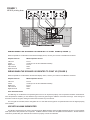
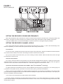
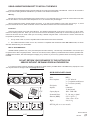
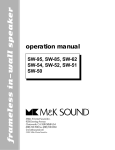
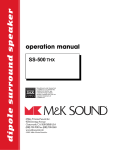
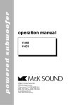
Miller & Kreisel Sound Corporation, USA • 9351 Deering Avenue, Chatsworth, CA 91311-5858 • 818-701-7010 fax 818-701-0369 • www.mksound.com
Miller & Kreisel Sound , EUROPE • Solrøed Center 12B, Level I • 2680 Solrøed Strand • Denmark • Tel: +45 56129047 • Fax: +45 56129045
M&K SOUND
TM
MP4512
5-CHANNEL SINGLE-SOURCE MONITOR
INSTALLATION MANUAL
Congratulations! You now own a true breakthrough product. The M&K MP4512 is a unique loudspeaker concept that provides highresolution reproduction of five channels of surround audio from a single cabinet utilizing M&K’s Tripole® Surround MatrixTM technology.
Unlike speakers that use electronic processing to create the illusion of surround only in a narrow “sweet spot,” the MP4512 disperses sound into the room using five separate speaker elements to produce a convincing surround field that can be enjoyed by multiple listeners over a broad listening area.
The MP4512 incorporates individual speakers for the left, center, right, left surround, and right surround channels. The left, center,
and right channel speakers have the identical elements as the acclaimed M&K Xenon LCR-25, each using a very high-performance 1”
fabric-dome Neodymium tweeter (with Ferrofluid) and a high-output 3.25” polymer-resin-coated-paper cone woofer.
The surround channels are reproduced by two high-quality 3” “wide-range” drivers, with one each mounted on the left and right sides
of the cabinet, respectively. Each channel utilizes M&K’s exclusive Phase-FocusedTM crossover, which is an element critical to the speaker’s ability to produce smooth response and even coverage of sound throughout the listening area.
Please take the time to read the following important information contained in this manual. It will help to ensure that you receive maximum performance from your MP4512 and understand why M&K is known as “The Choice Of Professionals.”
SPEAKER LOCATION
The MP4512 is magnetically shielded, so it can be placed directly on top of a direct-view television or directly above or below a flatscreen display device. It can be used in proximity to any television without distorting the picture.
The front baffle of the MP4512 is angled, to allow you to mount the speaker so that it either points up or points down, allowing you
to aim the speaker drivers towards the listener’s ears. In general, the speaker should be mounted so that it points up when it is mounted underneath the television display, and it should be mounted so that it points down when it is mounted above.
In order to determine the proper connection for the left and right channels (both front and side/surround), you first must select the
orientation of the speaker. Because the speaker can be oriented two ways, the speaker input terminals are labeled “1” and “2” instead
of “left” and “right.”
FIGURE 1
SIDE 1
FRONT 1
CENTER
FRONT 2
SIDE 2
MP4512 pointing down
WIRING WHEN THE SPEAKER IS ORIENTED TO POINT DOWN (FIGURE 1)
When the speaker is mounted above the television display device, connect your receiver to the MP4512 as follows:
Amplifier Channel
MP4512 Speaker Channel
Left Front
Center
Right Front
Left Surround
Right Surround
Front 1
Center (do not use the unlabeled terminals)
Front 2
Side 1
Side 2
WIRING WHEN THE SPEAKER IS ORIENTED TO POINT UP (FIGURE 2)
When the speaker is mounted below the television display device, connect your receiver to the MP4512 as follows:
Amplifier Channel
MP4512 Speaker Channel
Left Front
Center
Right Front
Left Surround
Right Surround
Front 2
Center (do not use the unlabeled terminals)
Front 1
Side 2
Side 1
Other Installation Notes
The M&K logo is not attached to the speaker grille so that it can be placed properly once the speaker orientation is determined.
Once the speaker is installed, you can attach the logo to the front grille using the adhesive on the back of the logo. Place the logo at
the bottom center of the grille, making sure that it does not block any of the drivers.
The front grille is removable, but the side grilles are not. Note that the front grille is not symmetrical and must be aligned properly
to be installed.
USE WITH AN M&K SUBWOOFER
The MP4512 is designed to be used in conjunction with an M&K subwoofer. Using an M&K subwoofer will give you true full-bandwidth performance with powerful low frequencies. All M&K subwoofer models are compatible with the MP4512. Please follow the
instructions provided with your subwoofer and receiver to properly connect the subwoofer.
FIGURE 2
MP4512 pointing up
SIDE 2
FRONT 2
CENTER
FRONT 1
SIDE 1
SETTING THE RECEIVER’S CROSSOVER FREQUENCY
When using the MP4512 with a subwoofer, the receiver’s internal crossover frequency should be set to a frequency between 100
and 200 Hz. The higher the crossover frequency, the greater the dynamic range and maximum output capability of the system.
If you have multiple choices, we recommend setting the crossover to 200 Hz or to the highest frequency available.
SETTING THE RECEIVER’S CHANNEL LEVELS
Note: These special instructions will differ from the instructions provided with your receiver. In order to take full advantage of the
MP4512’s capabilities, you need to follow these special instructions when setting channel levels.
Front Channels
For the Left, Center, and Right front channels, follow the receiver’s setup instructions. Because the MP4512 has identical speakers for each of these channels, the receiver’s level setting for all three channels must be identical.
Tip: If you do not have a sound level meter, you can use a setting of 0 dB as a default. Make sure that the left, center, and right
front channels are all set to 0 dB.
Side (Surround) Channels
Do not use a sound level meter to set the levels for the Left Surround and Right Surround channels. Instead, the level for these
channels should be set so they are 4 to 6 dB higher than the level of the front channels. For example, if the left, center, and right front
channels are set to 0 dB, set the Left Surround channel to + 6 dB and the Right Surround channel to + 6 dB.
Special Note On Side Channel Speaker Phase & M&K’s Tripole® Surround MatrixTM Technology
For proper performance of the MP4512, be sure to wire the MP4512 (as shown) with all (+) terminals on your receiver going to all
(+) terminals on the speaker and all (-) terminals on the receiver to the proper (-) terminals on the MP4512.
While a normal surround installation with multiple speakers throughout the room should have all speakers in the same acoustic
phase, the MP4512 is designed to have one surround channel acoustically out-of-phase with all the other channels. This helps to produce the most effective surround soundfield.
If you conduct an acoustic phase test, though, please note the following:
The Side 1 speaker is acoustically out-of-phase with the other channels. If you conduct a phase test of your system, you will find
that this surround channel is out of phase with all of the other channels. This is correct; do not change the wiring to this channel so that
all channels are in phase.
USING A MOUNTING BRACKET TO INSTALL THE MP4512
There are multiple threaded mounting inserts located at the center of the back baffle of the MP4512. These can be used with a
variety of wall and ceiling brackets available from your dealer or the bracket manufacturer.
Warning:
Because the crossover is located behind the mounting holes, it is very important that you do not let the screws extend more than
1/4” into the cabinet. If the screws extend deeper than a 1/4”, the crossover may be damaged.
When mounting the bracket, carefully tighten the screws. If you start to feel resistance to the screw, stop turning it. If, at that
point, the bracket isn’t secure, either use shorter screws or add washers between the screw head and the bracket.
Installation:
There are three inserts on the back of the MP4512. The speaker is shipped with a set screw in each insert. To use an insert,
remove the existing screw first. When you use a new screw to secure the bracket, please keep in mind the warning above. Do not
remove the set screw from an insert unless you are mounting a bracket using that insert. There must be a screw in each insert for
the speaker to perform properly.
1.
The top insert is 3/8”–16, and is compatible with the Omnimount 20.0 series of brackets.
2. The middle and bottom inserts are 1/4”–20, and each is compatible with the Monster Cable MM1UMK bracket, as well as
with other brackets using 1/4”-20 hardware.
M&K 10 YEAR WARRANTY
All M&K Satellite speakers carry a ten year limited parts and labor warranty. This warranty is transferable to new owners up to
ten years from the date of original purchase. It does not cover abuse, misuse, repairs by unauthorized service stations, speakers without M&K serial numbers, and those damaged in shipping or by accident. If you have any questions about the warranty, please contact M&K.
DO NOT RETURN YOUR SPEAKERS TO THE FACTORY FOR
SERVICE WITHOUT OBTAINING PRIOR AUTHORIZATION
If you have any further questions regarding your MP4512, please contact your M&K dealer or the M&K factory at (818) 701-7010.
You may also reach us through e-mail at [email protected].
SPECIFICATIONS
17 1/4"
Model:
Driver Complement:
Finish Options:
Impedance:
4 1/2"
5"
Frequency Response:
Recommended Power:
Dimensions (HxWxD):
18 1/2"
SIDE 1
FRONT 1
CENTER
FRONT 2
SIDE 2
Weight:
MP4512
3 x 3.25” mid-woofer
3 x 1” neodymium ferrofluid tweeter
2 x 3” mid-woofer (surrounds)
Black
8 ohms/mains
12 ohms/surrounds
100Hz - 23kHz ±2dB
25 - 200 watts per channel
4-1/2” x 18-1/2” x 5”
11.4cm x 47cm x 12.7cm
9 lbs./ 4.1 kg.
NOTE: Side grilles are not user removable.
MP-4512 Manual
PN#
08/13/04
pt/qrk