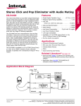
1
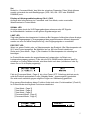
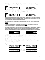
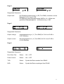
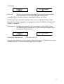
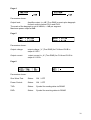
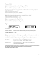
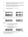
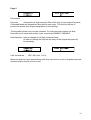
Bedienungshinweise
Operating Manual
BELL System Control
Power Amplifiers
SCA-2MR
SCA-4MR
1
Inhaltsverzeichnis:
Bedienelemente (Rückseite)
Seite
3
Bedienelemente (Front)
Seite
4
Funktionsablauf
Seite
6
View Mode
Seite
7
Command Mode
Seite 10
English manual:
Operational Features (rear panel)
page 14
Operational Features (front panel)
page 15
Functions and features (guideline)
page 17
View Mode
page 18
Command Mode
page 21
Specifications
SCA2MR
Power Output
500+500W/4Ω
1000+1000W/4Ω /2Ω
Freq. Resp.
10Hz - 40kHz/8Ω
10Hz - 40kHz / 8Ω
SNR(IHF-A)
110dB
110dB
2,7dBu(1,06Vrms)
2,7dBu(1,06Vrms)
Signal LED Indicator L&R
LED
LED
Protect LED Indicator L&R
LED
LED
Limit LED Indicator
LED
LED
automatic
automatic
Temperature Indicator
LCD Display
LCD Display
SCM Module Indicator
LCD Display
LCD Display
Input Damping readout
LCD Display
LCD Display
Input Sensitivity
L&R
Cooling Control System
SCA4MR
2
Bedienelemente (Rückseite)
SCA2MR
Netzbuchse Euro:
Mains Fuse:
230VAC
8AT (träge)
SCA4MR
Netzbuchse Powercon:
Mains Fuse:
Secondary Fuse:
230VAC
15AT (träge)
1AT (träge)
System Control Module (SCM modules) (SCA2MR / SCA4MR)
Die verwendeten Eingangsmodule sind mit denen der Baureihe SCA2 kompatibel.
XLR Eingang / Link CH.A / CH.B
ACHTUNG: Die Modelle SCA2MR und SCA4MR sind mit einer Schutzschaltung
gegen Überspannung am Eingang ausgestattet. Zur ordnungsgemäßen Funktion und
zur Vermeidung von Verzerrungen müssen alle über NF Kabel (XLR) eingangsseitig
verbundenen Endstufen netzseitig eingeschaltet sein!
Shield Lift Schalter mit LED Anzeige für Input CH.A / CH.B.
Shield Lift aktiv (grüne LED an) bewirkt, daß die Abschirmung des Eingangskabels,
welches im Normalfall Massepotential hat, von der Masse der Endstufe getrennt ist.
Es ist darauf zu achten, daß mindestens eine Masseverbindung zwischen Mischpult
und jeder einzelnen Endstufe besteht, da alle Eingänge elektronisch symmetrisch sind.
GND / LIFT Schalter
In „GND“ Position ist die Schutzerde mit der Masse der Endstufe verbunden. Brummschleifen können ggfls. durch Umschalten in Position „LIFT“ aufgehoben werden.
Data IN
XLR Buchse + Link für den Dateneingang der RS485 Schnittstelle. Dient zur Fernsteuerung / Überwachung der SCA-2/4MR.
(Funktion steht mit der Software Release 1.0 noch nicht zur Verfügung).
Impedance Mode Schalter mit Led (SCA-4MR)
Anpassung der Verlustleistung für optimierte Betriebssicherheit in Abhängigkeit
zu der an den Lautsprecherausgängen angeschlossenen Impedanz. Der gewählte
Modus wird im Display [View Mode , Page 1] angezeigt.
Der 4 Ω Mode wird zusätzlich durch die gelbe Led (an) gekennzeichnet.
Die pro Lautsprecherausgang angeschlossene Gesamtast darf im 2Ω Mode die Impedanz von 2Ω und im 4Ω Mode die Impedanz von 4Ω nicht unterschreiten.
Das Umschalten des Impedanz Modus während des Betriebs ist zu vermeiden.
Temperaturgesteuerte Lüfter
Air flow direction: to front. Rack im Betrieb vorne und hinten offen halten.
3
Bedienelemente Front
Netzschalter (Mains)
Einschalten der Endstufe zum Normal- und Standby Betrieb. Anzeige über Hintergrundbeleuchtung der Dispays.
Level Regler (CH.A / B)
Einstellung der Dämpfung des Eingangssignals in ‚dB‘. Der eingestellte Wert wird im
Display angezeigt. [View Mode , Page 1] Dämpfung: max 88dB, min. 0.0dB.
Remote Active Schalter (mit Led)
Aktiviert den Remote Control Modus. Anzeige durch rote Led (an).
Das Aktivieren/Deaktivieren des Remote Control Modus erfolgt zusätzlich über einen
„Fade In“ um einen eventuellen Pegelunterschied während des Betriebs sanft auszugleichen.
Remote Control Modus*
ermöglicht die Fernsteuerung und -überwachung der Endstufe mittels externem
Controller. Der Datenaustausch erfolgt via RS485 Schnittstelle. Alle notwendigen
Parameter werden im [Command Mode, Page 1] eingestellt.
Das Aktivieren dieses Modus kann vom User per Software unterdrückt werden.
[Command Mode, Page 4]. Ist Remote Control aktiv, so ist der „Command Mode“ automatisch deaktiviert um interne und externe Überlagerung von Befehlen zu verhindern.
*Diese Funktion steht in der Software Release 1.0 nicht zur Verfügung.
Command Schalter (mit Led)
Wechselt zu einem beliebigen Zeitpunkt zwischen „Command“- und „View Mode“.
Der „Command Mode“ wird zusätzlich durch das Leuchten der grünen Led gekennzeichnet. Bei Verlassen des „Command Mode“ wird der zuletzt geänderte Wert automatisch gespeichert, auch wenn dieser vorher nicht mit „Enter“ bestätigt wurde.
Das Aktivieren des „Command Mode“ kann mittels Keycode geschützt werden.
[Command Mode , Page 5]
Siehe auch Erklärung der Funktionen „Command“- und „View Mode“
Page/Exit Taste
Wechselt im „Command“- und „View Mode“ zur nächsten Seite. Hierbei wird automatisch der zuletzt geänderte Wert gespeichert, auch wenn dieser nicht mit „Enter“ bestätigt wurde.
Set/Enter
Durch Drücken des Wheels wird die Funktion „Enter“ ausgeführt. Durch
Drehen des Wheels nach links oder rechts wird die Funktion „Set“ ausgeführt.
Enter
springt im Command Mode von einem zu ändernden Parameter zum nächsten. Dabei
werden die Daten, falls verändert, gespeichert. Der zu ändernde Parameter wird im
Display blinkend dargestellt. Enter bestätigt bei numerischen Eingaben die einzelne
Ziffer (z.B. bei Eingabe des Keycodes).
4
Set
Ändert im „Command Mode“ den Wert der einzelnen Parameter. Diese Werte können
sowohl numerisch als auch Bestätigungen (YES / NO, ON / OFF oder ENABLE /
DISABLE) sein.
Display mit Hintergrundbeleuchtung CH.A / CH.B
Anzeige aller Informationen im Command- und View Mode, sowie eventueller
Warnhinweise im Protect Mode.
SIGNAL LED
Anzeige eines durch die XLR Eingangsbuchsen ankommenden NF Signals.
Im Normalbetrieb leuchten nur die grünen Signalanzeigen auf.
LIMIT LED
Zeigt das Arbeiten des integrierten Limiters an.Bei längerem Aufleuchten dieser Anzeige
sollte der Eingangspegel (= Ausgangspegel des angeschlossenen Mixers) abgesenkt
werden um eine zu starke Komprimierung des Eingangssignals zu vermeiden.
PROTECT LED
Warnt vor einem Defekt, oder vor Übertemperatur der Endstufe. (Bei Übertemperatur ab
90¯C wird Protect ausgelöst. Bei Abkühlen auf ca. 80° wird Protect deaktiviert.
Siehe auch [View Mode , Page 1] Die Ursache für Übertemperatur ist unbedingt zu
beseitigen.
Im Protect Mode werden die angeschlossenen Lautsprecher via Relais vom
Lautsprecherausgang getrennt. Falls sich die SCA-2/4MR bereits während des Einschaltens im Protect Mode befindet, wird dies direkt nach dem „Initialisieren“ des Systems für ca. 5s in Display angezeigt.
Falls im [Command Mode , Page 4] die „Auto Power OFF“ Schaltung aktiviert wurde,
wird die Endstufe automatisch in den „Standby Mode“ (spannungsfrei) geschaltet.
Sie wird somit zusätzlich gegen mögliche Folgen von Überlastung geschützt.
Eine genaue Beschreibung dieser Funktion findet sich unter ‚Funktionsablauf‚ (Punkt 3).
Im Protect Mode sind folgende Funktionen deaktiviert:
[View Mode , Page 3]
[View Mode , Page 4]
[View Mode , Page 5]
[Command Mode , Page 2]
[Command Mode , Page 3]
5
Funktionsablauf
1) Vor dem Einschalten der Endstufe ist durch den „Impedance Mode“ Schalter (Rückseite) die angeschlossene Last (Lautsprecher) zu wählen: 2Ω / 4Ω (nur bei SCA4MR).
Werden pro Seite Lautsprecher mit einer Gesamtimpezanz von grösser gleich 4Ω
betrieben, so ist der 4Ω Mode einzustellen. Werden pro Seite Lautsprecher mit einer
Gesamtimpedanz unter 4Ω betrieben, so ist der 2Ω Mode zu wählen.
Anzeige des gewählten Modus im Display [View Mode , Page 1].Der 4 Ω Mode wird
zusätzlich durch eine gelbe Led (neben Imepdance Mode Schalter) angezeigt.
Das Umschalten des Impedance Modus des Betriebs während des Betriebs ist zu
vermeiden.
2) Nach dem Einschalten der SCA-2MR/4MR wird das System des Amps initialisiert.
Hierbei zeigen die Displays folgende Information:
3) Falls im [Command Mode, Page 4] der „Sine Wave Test“ aktiviert wurde, wird dieser
jetzt ausgeführt. Dieser Test dient der Überprüfung der am Lautsprecherausgang angeschlossenen Komponenten.
Das System überprüft innerhalb des zuvor gewählten Frequenzbereichs mit der gewählten Verstärkerausgangsleistung [Command Mode , Page 2/3] die Gesamtimpedanz
der pro Verstärkerseite angeschlossenen Lautsprecher incl. Kabel.
Das Scannen des jeweiligen Frequenzfensters ist akustisch, in Abhängigkeit zur programmierten Ausgangsleistung, durch das angeschlossene Lautsprechersystem zu
hören. Warnung - Vorsicht bei zu hoher Lautstärke !!!
Das Testergebnis wird auf den Displays für den jeweiligen Endstufenkanal (CH.A /
CH.B) separat angezeigt.
Falls im [Command Mode , Page 4] die „Auto Power OFF“ Schaltung aktiviert wurde
und das System an einem der beiden Lautsprecherausgänge einen Kurzschluß oder
Unterimpedanz (R << 2Ω im 2Ω Mode oder R << 4Ω im 4Ω Mode) feststellt, wird die
Endstufe in den „Standby Mode“ (spannungsfrei) geschaltet und somit gegen Überlastung und deren Folgen geschützt.
Um den „Standby Mode“ zu deaktivieren muß der Verstärker erneut eingeschaltet
werden. Vorher ist die Ursache für das Aktivieren des „Standby Mode“ zu beseitigen:
z.B. defektes Lautsprecherkabel, beschädigter Lautsprecher usw.
6
Falls im [Command Mode , Page 5] „Keycode“ aktiviert wurde, zeigen die Displays
folgende Information:
A
Der „Standby Mode“ kann nur aufgehoben werden wenn die Ursache des Fehlers beseitigt wird, oder der korrekte Keycode eingegeben wird, um die Fenster zum
Deaktivieren von „Power Control“ und „Sine TEST“ zu öffnen.
B
Wird jetzt in diesem neuen Fenster „Power Control“ deaktiviert, so wird nach erneutem
Einschalten der Endstufe der „Standby Mode“ auch dann nicht aktiviert, wenn sich z.B.
ein Kurzschluß am Lautsprecherausgang befindet.
Bei aktiviertem „Sine Wave Test“ ist das Deaktivieren von und „Power Control“ nicht
ratsam!
Falls im [Command Mode, Page 5] der „Keycode“ nicht aktiviert wurde, zeigen die
LCD’s gleich die neben ‚B‘ gezeigten Informationen.
4) Falls der Eingangslevel von CH.A oder CH.B eine geringere Dämpfung als -30dB hat
[View Mode , Page 1] wird jetzt die „Auto Fade In“ Funktion aktiviert.Diese Funktion
fährt den Ausgangspegel der Endstufe sanft hoch und verhindert so einen sprunghaften
Lautstärkeanstieg bei anliegendem Eingangssignal.
5) In Abhängigkeit des „Command“ Schalters werden nun auf den Displays die Funktionen des „Command“- oder „View“ Mode dargestellt.
View Mode
Das Aktivieren dieser Funktion erfolgt durch Umschalten des „Command“ Schalters.
(Grüne Led aus) wenn der View Mode aktiviert wurde. Die Anwahl der nächsten Seite
erfolgt durch die „Page/Exit“ Taste.
Page 1
7
Dargestellte Parameter
SCM Module
Zeigt den Typ des eingebauten SCM (Control Moduls) für CH.A und CH.B an.
Impedance Mode (SCA4MR)
Zeigt den mittels Impedance Mode Schalter gewählten Betriebsmodus (2 Ω/ 4 Ω) an.
Level
Die mit dem Level Regler, bzw. per Remote Control eingestellte Dämpfung des Eingangssignals in „dB“ für CH.A und CH.B.
Heat sink temperature
Anzeige der Betriebstemperatur In °C für CH.A und CH.B.
Page 2
Dargestellte Parameter
Remote address:
Remote Control Adresse der einzelnen Endstufe
Baud Rate:
Übertragungsgeschwindigkeit der RS485 Schnittstelle
Remote Level:
Die im Command Mode bzw per Remote Control
eingestellte Dämpfung des Eingangssignals in „dB“
für CH.A und CH.B
Page 3
Dargestellte Parameter
Output power
Anzeige der Endstufenausgangsleistung von CH.A und CH.B in Watt (True RMS). numerisch und als Bargraph.
Die Skalierung des Bargraph beträgt bei der SCA4MR 100W / Div. = 50W per angezeigtem Bargraphsegment.
Die Skalierung des Bargraph beträgt bei der SCA2MR 50W/Div., = 25W per angezeigtem Segment.
8
Page 4
Dargestellte Parameter:
Output level:
Die Endstufenaussteuerung in „dB“ (True RMS) numerisch und als
Bargraph für CH.A und CH.B .
Die Skalierung des Bargraph beträgt 2dB/Div, d.h. 1dB per dargestelltem Bargraphsegment . Vollaussteuerung = 0dB.
Page 5
Dargestellte Parameter:
Output voltage:
Ausgangsspannung in „V“ (True RMS) für CH.A und CH.B in
0.25V Schritten .
Output current:
Der Ausgangsstrom in „A“ (True RMS) für CH.A und CH.B in
0.125A Schritten.
Page 6
Dargestellte Parameter:
Sine Wave Test:
Status:
ON / OFF
Power Control:
Status:
ON / OFF
TXD:
Status:
Symbol bei Daten senden über RS485
RXD:
Status:
Symbol bei Daten empfangen über RS485
9
Command Mode
Das Aktivieren dieser Funktion erfolgt mit dem „Command“ Schalter (grüne LED an)
Eine ausführliche Beschreibung dieser Funktion befindet sich unter:
Bedienungselemente auf der Frontwand, „Command“ Schalter.
Das Anwählen und Bestätigen des zu ändernden Parameters erfolgt mit der „Enter“
Taste des Wheels.
Eine ausführliche Beschreibung dieser Funktion befindet sich unter:
Bedienungselemente auf der Frontwand, „ENTER“.
Das Ändern des angewählten Parameters erfolgt mit dem „Wheel“.
Eine ausführliche Beschreibung dieser Funktion befindet sich unter:
Bedienungselemente auf der Frontwand, „SET „.
Das Anwählen der nächsten Seite erfolgt mit der „Page/Exit“ Taste.
Eine ausführliche Beschreibung dieser Funktion befindet sich unter:
Bedienungselemente auf der Frontwand, „Page / Exit „.
Page 1
Parameter:
Remote address:
Remote Control Adresse der einzelnen Endstufe.
Einstellbarer Wertebereich: 1 - 225. Der Datenaustausch zwischen allen Endstufen und
dem externen Controller erfolgt über die RS485 Schnittstelle. Um eine bestimmte Endstufe direkt anzusprechen benötigt der Controller deren genaue Adresse.
Diese Adresse darf jeweils nur einmal für eine SCA-2/4MR vergeben werden, um eine
Datenkonflikt zu vermeiden.
Baud Rate:
Baud.
Die Übertragungsgeschwindigkeit der RS485 Schnittstelle in
Einstellbarer Wertebereich: 9600 / 19200 / 28800 / 57600 .
Remote Level:
Dämpfung des Eingangssignals in „dB“ für CH.A und CH.B, wenn
„Remote Control“ aktiviert wurde.
Dieser voreingestellte Wert wird vom System übernommen, falls noch keine Kommunikation zwischen externem Controller und SCA-2/4MR stattgefunden hat. Einstellbarer
Wertebereich: -88dB - 0.0dB .
10
Page 2
Diese Funktion dient der Überprüfung der am Lautsprecherausgang angeschlossenen
Komponenten mit Hilfe eines durchstimmbaren, digitalen Sinusgenerators. Die Ausgangsleistung , Start- und Stoppfrequenz des Generators sind frei programmierbar.
Die hier festgelegten Werte werden auch für die automatische Impedanzkontrolle nach
dem Einschalten der SCA-2/4MR verwendet, falls diese unter [Command Mode , Page
4] aktiviert wurde. (Siehe auch unter Funktionsablauf , Punkt 3 ).
Das System überprüft innerhalb des zuvor eingestellten Frequenzbereichs mit der zuvor
eingestellten Verstärkerausgangsleistung die Gesamtimpedanz der pro Kanal angeschlossenen Lautsprecher incl. Kabel.
Das Scannen der jeweiligen Frequenz ist akustisch, in Abhängigkeit zur programmierten
Ausgangsleistung durch die angeschlossenen Lautsprecher zu hören.
—> Vorsicht bei zu hoher Lautstärke !!!
Das Testergebnis wird auf den Displays für ca. 5s angezeigt.
Im Gegensatz zur automatischen Impedanzkontrolle besteht hier nicht die Möglichkeit
im Fall einer analysierten „Unterimpedanz“ die Endstufe in den „Standby“ Mode zu
schalten.
Vielmehr wird die Ausgangsleistung des Sinussignals auf 4W max. reduziert, um die
Belastung der Endstufe im Fall eines Kurzschlusses zu minimieren.
Gleiches gilt für die automatische Impedanzkontrolle.
Nach Abschluss des Tests erfolgt ein „Fade In“ des Eingangssignals um einen sprunghaften Anstieg der Lautstärke auf ggfls. bis zu 1000W sanft auszugleichen, falls die
Dämpfung des Eingangssignals kleiner -30dB ist.
Parameter
Output Power:
Ausgangsleistung des Sinusgenerators in Watt für Kanal A.
Diese Leistungsangabe bezieht sich bei der SCA-2MR auf 4Ω und bei der SCA-4MR
auf 2Ω bzw. 4Ω (je nach gewähltem Impedanz Modus).
Die Meßgenauigkeit der Impedanzprüfung steigt mit zunehmender Ausgangsleistung.
Es muss daher ein Kompromiss zwischen Lautstärke und Messgenauigkeit gefunden
werden.
Einstellbarer Wertebereich: 2W / 4W / 8W / 16W / 32W / 64W / 128W .
11
Start:
Startfrequenz des digitalen Sinusgenerators. Um Frequenzüberlappungen
zu verhindern, ist diese maximal gleich der Stoppfrequenz.
Einstellbarer Wertebereich: 50Hz - 10KHz .
Stop:
Stopfrequenz des digitalen Sinusgenerators. Um Frequenzüberlappungen
zu verhindern, ist diese minimal gleich der Startfrequenz.
Einstellbarer Wertebereich: 50Hz - 10KHz .
Test:
Startet die Testprozedur.
Einstellbarer Wertebereich: YES / NO .
Page 3
Diese Funktion ist identisch mit der von Page 2, überprüft jedoch CH. B .
Page 4
Parameter:
Sine Test:
Aktiviert die automatische Impedanzkontrolle.
Siehe Funktionsablauf , Punkt 3 .
Einstellbarer Wertebereich: ON / OFF.
Power CTRL:
Aktiviert die „Auto Power Off“ Schaltung.
Siehe Bedienungselemente auf der Frontwand -PROTECT LED
sowie auch Funktionsablauf , Punkt 3 .
Einstellbarer Wertebereich: ON / OFF.
Remote Control: Erlaubt / verbietet das Aktivieren des Remote Control Modus mit dem
„Remote Active“ Schalter. Siehe Bedienungselemente auf der Frontwand -“Remote
Active“ Schalter. Einstellbarer Wertebereich: ENABLE / DISABLE .
*(Funktion steht mit der Software Release1.0 nicht zur Verfügung).
Page 5
12
Parameters:
Keycode:
Aktiviert den vierstelligen Keycode. Nach dessen Eingabe wird der
Command Mode nur noch durch Eingabe des Keycode
zugänglich.Diese Funktion verhindert unbefugte Änderung von Daten.
Der Keycode kann erst aktiviert werden, wenn zuvor mit Hilfe der Funktion „New
Keycode“ eine Code eingegeben und gespeichert wurde.Einstellbarer Wertebereich:
ENABLE / DISABLE .
New Keycode: Eingabe oder Änderung eines vierstelligen, numerischen Codes.
Die Änderung des Keycodes ist nur nach vorheriger Eingabe des ursprünglichen Codes möglich.
Einstellbarer Wertebereich:
YES / NO und 0 - 9.
Den Keycode unbedingt an einer sicheren Stelle aufbewahren. Entsperren bei verlorenem Keycode ist nur durch kostenpflichtigen Service möglich.
13
Operational Features (rear panel)
SCA2MR
Mains socket with integrated fuse holder
Socket typ: 230VAC, Euro type.
Fuse: 8AT (slow blow).
SCA4MR
Mains socket: Powercon: 230VAC
Mains Fuse: 15AT (slow blow).
Secondary Fuse: 1AT (slow blow).
System Control Module (SCA2MR / SCA4MR)
The system control modules (SCM modules) are compatible with those used in the
SCA2M power amplifier.
XLR Input / Link CH.A / CH.B
Warning: Both models SCA2MR and SCA4MR feature protection cirtuits against
overvoltage. For proper function and to avoid audible distortion, all power amps which
are connected via XLR input cables must be connected to Mains and must be switched
on.
Shield Lift switch with LED indicator for Input CH.A / CH.B.
Shield Lift active (green LED on) cuts the screen of the incoming signal cable from the
Ground of the Power Amplifier.
In any case, at least one Ground connection (screen) between the signal source
(mixer) and each power amplifier must be connected (all inputs are electronically
balanced).
GND / LIFT Switch
When in „GND“ position, the Earth (Mains) is connected to GND (ground) of the power
amplifier circuit. Humnoise from ground loops may be eliminated by setting the switch
to ‚LIFT‘ position.
Data IN
XLR socket + link for data input from RS485 port. Feature for remote control and remote
operation.(function not activated in software release 1.0 )
Impedance Mode switch with Led indicator (SCA-4MR)
feature to optimize the drain power and the safe operation of the amplifier in connection
with the impedance of the driven loudspeaker(s). Selected mode is shown in the
frontside display [View Mode , Page 1].
In addition, the 4Ω mode is indicated by a yellow Led (on).
In 2Ω mode, the total load connected to each speaker output must not drop under 2Ω.
In 4Ω mode the minimum impedance is 4Ω.
Do not manipulate the impedance mode switch while power amplifier is in use.
Automatic temperature controlled cooling fans
Air flow direction:back to front. Keep airflow free from any kind over covers.
14
Operational Features (front panel)
Mains switch
On/ off switch for normal- and standby operation. ‚ON‘ is indicated by the backlights of
the LCD displays.
Level Control (CH.A / B)
Sets the input signal damping in ‚dB‘. The actual setting is shown in the display.
[View Mode , Page 1] damping: max 88dB, min. 0.0dB.
Remote Active switch with led indicator
Activates the remote control mode. ( red Led (on)).
The remote control mode works in parallel to a ‚fade in‘ function to avoid harsh level
offsets.
Remote Control Mode*
Enables the remote control and supervision of the SCA2MR /4MR using an external
control unit. Data exchange via RS485 port. All necessary parameters are to be
selected in [Command Mode, page 1].
This mode may be disabled by the user.
[Command Mode, Page 4]. When remote control is active, the „command mode“ will be
automatically deactivated to avoid software conflicts.
*this function is not activated in software release 1.0
Command switch (with led indicator)
Switches at any time from „Command“- to „View Mode“ and reverse.
„Command Mode on“ is indicated by an addition green led indicator. When leaving
„Command Mode“ any manipulation of parameters will automatically be safed, even
when ‚Enter‘ was not operated.
„Command Mode“ section may be protected by a keycode (numeric password).
[Command Mode , Page 5]
Re.: functions of „Command“- und „View Mode“
Page/Exit button
Jumps to the next page ( in „Command“- and „View Mode“) Any manipulation of
data will automatically be safed without operating ‚Enter‘ button.
Set/Enter
By pushing the wheel, the „Enter“ order is executed. Turning the wheel to either
direction will activate the ‚Set‘ function.
Enter
In Command Mode pressing ‚Enter‘ will jump from parameter to parameter. Any
manipulation of data will automatically be stored. The next parameter to be modified is
shown in cursor mode. Press enter for each new digit to be stored.
15
Set
When in „Command Mode“ , set will manipulate the values of individual parameters.
These entries may be numeric or confirmations such as YES / NO , ON / OFF or
ENABLE / DISABLE.
LCD Display with backlight CH.A / CH.B
Display of all important data and messages in Command- and View Mode plus eventual
warnings in Protect Mode.
SIGNAL LED
Indicates ‚signal present at amplifier output socket‘
Normally, only the ‚gren‘ led indicators will be on.
LIMIT LED
Indicates that the built-in limiters are active. When this indication is permanent, please
reduce the input level (= the output level of the connected mixer) to avoid heavy
compression of the audio signal.
PROTECT LED
Indicates a defect or a state of overheat. When the temperature of the power amplifiers
exceeds 90°C, Protect will be active. After cooling down to below 80°C, Protect will be
inactivated. [View Mode, Page 1] The physical cause of Protect must be found and
eliminated.
Protect Mode will disconnect the speaker outputs via relais. Should the SCA-2/4MR
remain in Protect Mode after any initial ‚mains on‘, this state will be indicated for
a period of 5sec. after ‚INIT‘
If [Command Mode , Page 4] „Auto Power OFF“ has been activated, the power
amp section will switch to „Standby Mode“ (power supply off).
This feature serves to protect the power amplifier from additional overload.
Fore further information, please refer to ‚Function Guide‚ (page 3).
Protect - Mode will deactivate the following features:
[View Mode , Page 3]
[View Mode , Page 4]
[View Mode , Page 5]
[Command Mode , Page 2]
[Command Mode , Page 3]
16
Functions and features (guideline)
1) Before switching on ‚mains‘, the Impedance Mode switch (rear panel) must be set to
match the minimum impedance of the connected loudspeaker(s).
2Ω / 4Ω (only for SCA4MR). When the total speaker impedance for one channel is
below 4Ω, set the impedance switch to 2Ω. In any other case set it to 4Ω
Impedance setting is shown in display [View Mode , Page 1].In addition, the 4Ω mode is
indicated by a yellow Led (next to impedance mode switch).
Do not operate the impedance mode switch while the power amp is in use.
2) After switching on Mains, System Init is started. The Display will show:
3) If - in [Command Mode, Page 4] the „Sine Wave Test“ has been activated, it will now
be executed. This test will check the the components which are connected to the
speaker outputs.
Within the programmed frequency window and at the preselected power output
[Command Mode , Page 2/3], the total impedance of the connected speaker systems
plus cables will be measured. The frequency sweep within the selected window will be
heard through the connected speakers.
Warning - Excessive output power may cause physical damage
The test result willbe shown for each Channel:
If in [Command Mode , Page 4] „Auto Power OFF“ has been activated, and if the
system detects any short circuit or excessive low impedance at one of the speaker
outputs, (R <<2Ω in 2Ω Mode or R << 4Ω im 4Ω Mode), the power amplifier will switch
to „Standby Mode“ (power supply off) in order to protect it against further overload or
damage.
In order to deactivate „Standby Mode“, the power must be switched off - and back to on.
In any case, the cause of setting the power amp to ‚Standby Mode‘ must be eliminated.
Check speaker cables for short circuits or loudspeaker systems for defects.
17
If in [Command Mode , Page 5] „Keycode“ has been activated, the displays will show:
Quit Standby Mode by eliminating the problem (for example short circuit at output) or by
A
entering the correct keycode.
Now the window to deactivate „Power Control“ and „Sine TEST“ will open.
If ‚Power Control‘ is deactivated in this new window, ‚Stand by Mode‘ will be inactive
B
after Mains off / on - even if the original problem (short circuit at speaker output) has not
been eliminated.
When „Sine Wave Test“ is activated, „Power Control“ should not be deactivated!
If in [Command Mode, Page 5] the „Keycode“ function has not been activated, the LCD
Displays will show the information as under ‚B‘.
4) Should the input level of CH.A or CH.B have a damping below 30dB,
[View Mode , Page 1] the „Auto Fade In“ function will now be activated. This feature will
softly fade in the output level of the power amplifier in order to avoid any harsh or
unexpected loudspeaker signals.
5) In conjunction with the „Command“ switch, the displays will now show the functions
of the „Command“- or „View“ mode.
View Mode
This function is activated by pushing the „Command“ switch (green LED off)
when View Mode has been activated. Select the next page by operating the page / exit
key.
Page 1
18
Parameters shown in Display
SCM Module
Shows type of SCM module used in CH.A and CH.B.
Impedance Mode (SCA4MR)
Shows the selected minimum output impedance (2Ω / 4Ω).
Level
Indicates the input damping as set by the Level control or via external remote controller.
Heat sink temperature
Actual operating temperatur in °C of CH.A and CH.B.
Page 2
Parameters in Display
Remote address:
Remote Control Address of one individual power amplifier
Baud Rate:
transmission speed of the RS485 port
Remote Level:
Actual Input daming set for CH.A and CH.B (display in dB)
Page 3
Parameters shown in display:
Output power
Informs the actual power output of CH.A and CH.B in Watts (True RMS / numeric plus
bargraph).
Scale of bargraph for SCA4MR is 100W / div. = 50W per segment.
Scale of bargraph for SCA2MR is 50W / div. = 25W per segment.
19
Page 4
Parameters shown:
Output level:
Amplifier output in „dB“ (True RMS) numeric plus bargraph
for each output channel CH.A and CH.B
The scale of the bargraph is set to 2dB/div, = 1dB per segment.
Maximum power output at 0dB.
Page 5
Parameters shown:
Output voltage:
output voltage „V“ (True RMS) for CH.A and CH.B in
steps of 0.25V.
Output current:
output current in „A“ (True RMS) for CH.A and CH.B in
steps of 0.125A.
Page 6
Parameters shown:
Sine Wave Test:
Status:
ON / OFF
Power Control:
Status:
ON / OFF
TXD:
Status:
Symbol for sending data via RS485
RXD:
Status:
Symbol for receiving data via RS485
20
Command Mode
Activate this feature via „Command“ switch (green LED on)
Find more detailed information in:
Operational Features (front panel) „Command“ switch.
Selection and confirmation of any point to be modified will be executed by the ‚Enter‘
button of the wheel.
Find more detailed information in:
Operational Features (front panel) „ENTER“.
Modification of any selected parameters is executed by the „wheel“.
Find more detailed information in:
Operational Features (front panel) „SET „.
To jump menu pages, use the „Page/Exit“ key.
Find more detailed information in:
Operational Features (front panel) „Page / Exit „.
Page 1
Parameters:
Remote address:
Remote Control address of any individual power amplifier.
Possible addresses: 1 - 225.
Data communication between all linked power amplifiers and the external controller via
RS485 port. In order to communicate with any specific power amplifier, the controller
must have its exact address.
In order to avoid data conflicts. each power amplifier must have different address.
Baud Rate:
Transmission speed of the RS485 port in baud.
Speed selector: 9600 / 19200 / 28800 / 57600 .
Remote Level:
Input signal damping in „dB“ for CH.A and CH.B, when
„Remote Control“ is active.
This preselected value will be kept by the system as long as no communication between
the external Controller and the SCA-2/4MR has instructed otherwise.
Selectable range: -88dB - 0.0dB .
21
Page 2
This feature will check all connected loudspeakers and cables. It makes use of an onboard digital sine wave generator with frequency sweep.
Power output as well as the sweep range (frequency window with start and stop entry)
are selected by the user.
Selected values are also used to execute the automatic impedance control (right after
mains switch ‚on‘) if this function has been activated under [Command Mode , Page 4]
More information in‘Funcions and features guideline p.3
Within the selected frequency range and output power, the system will check the total
impedance of loudspeakers and cables connected to the speaker outputs.
The frequency sweep within the selected range will be audible through the connected
speaker system(s).
—> Beware of excessive audible output levels
The test result will be shown in the display for a period of 5sec.
Unlike in the automatic impedance control mode, any state of low impedance or short
circuit will not switch the power amplifier into ‚stand by mode‘.
The output power of the sine wave signal will however be reduced to 4W max. in order
to minimize any possible dangers for the power amplifiers. The same is true for the
automatic impedance control.
Following this test is a soft „Fade In“ of the input signal. This fade in helps to avoid any
sudden offset of extremely high volumes (high SPL from speakers) if the input damping
is set below -30dB.
Parameters
Output Power: Output power of the sine wave generator for CH.A.
Output power reading refers to 4Ω load for SCA-2MR.
For SCA-4MR it refers to a 2Ω or a 4Ω load - depending on Impedance Mode setting.
The accuracy of the impedance measurement will increase with rising output power.
Possible settings for power output to execute impedance measurement:
2W / 4W / 8W / 16W / 32W / 64W / 128W .
22
Start:
set start frequency of the digital sine wave generator. In order to avoid
overlapping frequencies, the start frequency may not be set to any value
above the stop frequency. Range: 50Hz - 10kHz.
Stop:
set stop frequency of the digital sine wave generator. In order to avoid
overlapping frequencies, the stop frequency may not be set to any value
below the start frequency. Range: 50Hz - 10kHz.
Test:
Starts frequency sweep within the set paramenters
User command: YES / NO .
Page 3
This function is identical to that of page 2, however it serves to check CH.B
Page 4
Parameters:
Sine Test:
Activates the automatic impedance check.
(as in funcions and features guideline p.3)
User command: ON / OFF
Power CTRL:
Activates the „Auto Power Off“ function
Re.: Protect LED at front
(as in funcions and features guideline p.3)
User command: ON / OFF
Remote Control*: Enables / disables remote control via the „Remote Active“ switch.
Re.: operational features (front): “Remote Active“ Switch.
User command: ENABLE / DISABLE .
*(function disabled in software release 1.0).
23
Page 5
Parameters:
Keycode:
Activates the 4-digit keycode. After initial entry of your original keycode,
Command Mode will demand this keycode for each entry. This function serves to
protect the system from illegal manipulation of use settings.
The keycode function may only be activated, if a code has been entered as ‚New
Keycode‘ and if is has been stored. User commands: ENABLE / DISABLE.
New Keycode: Input or change of a 4 digit numerical Code.
In order to change the keycode the entry of the original keycode will
be necessary.
User commands:
YES / NO and 0 to 9.
Memorize and save your personal keycode. Any reset due to a lost or forgotten keycode
requires factory service at user‘s cost.
24