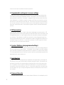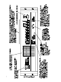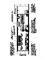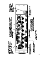
1
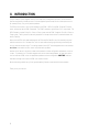
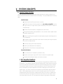
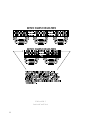
Film-Tech The information contained in this Adobe Acrobat pdf file is provided at your own risk and good judgment. These manuals are designed to facilitate the exchange of information related to cinema projection and film handling, with no warranties nor obligations from the authors, for qualified field service engineers. If you are not a qualified technician, please make no adjuatments to anything you may read about in these Adobe manual downloads www.film-tech.com DCM Series Digital Cinema Monitor & Crossover System U S E R M A N U A L The DCM hardware unit and DCM Commander software are the property of QSC Audio Inc. Information in this document is subject to change without notice and does not represent a commitment on the part of QSC Audio. The software described here is furnished under a licensing agreement. It is against the law to copy the software on any medium except as specifically allowed in the licensing agreement. DCM Commander is a trademark of QSC Audio Products, Inc; Windows and Windows 95 are trademarks of Microsoft Corporation; IBM is a registered trademark of IBM Corporation; Pentium is a registered trademark of Intel Corporation. 1999 QSC Audio Inc. All rights reserved. Printed in USA. Document Number 600019-A I. Introduction . . . . . . . . . . . . . . . . . . . . . . . . . . . . . . . . . . . . . . . . . . . . . . . . . . . . . . . . . . . . . . . . . . . . . . . . . . . . . . . . 1 II. System Requirements . . . . . . . . . . . . . . . . . . . . . . . . . . . . . . . . . . . . . . . . . . . . . . . . . . . . . . . . . . . . . . . . . . . . 2 III. Package Contents . . . . . . . . . . . . . . . . . . . . . . . . . . . . . . . . . . . . . . . . . . . . . . . . . . . . . . . . . . . . . . . . . . . . . . . 3 III. System Concepts . . . . . . . . . . . . . . . . . . . . . . . . . . . . . . . . . . . . . . . . . . . . . . . . . . . . . . . . . . . . . . . . . . . . . . . . 4 A. System Design Features . . . . . . . . . . . . . . . . . . . . . . . . . . . . . . . . . . . . . . . . . . . . . . . . . 4 1. QSC Amplifier Dataports . . . . . . . . . . . . . . . . . . . . . . . . . . . . . . . . . . . . . . . . . . . . . 4 2. Programmable routing and crossover settings . . . . . . . . . . . . . . . . . . . . . . . . . . . 5 3. DSP processing . . . . . . . . . . . . . . . . . . . . . . . . . . . . . . . . . . . . . . . . . . . . . . . . . . . . . 5 4. Speaker Database . . . . . . . . . . . . . . . . . . . . . . . . . . . . . . . . . . . . . . . . . . . . . . . . . . . 5 5. Fault Analysis . . . . . . . . . . . . . . . . . . . . . . . . . . . . . . . . . . . . . . . . . . . . . . . . . . . . . . 5 6. Password Security . . . . . . . . . . . . . . . . . . . . . . . . . . . . . . . . . . . . . . . . . . . . . . . . . . 5 7. Emergency Bypass . . . . . . . . . . . . . . . . . . . . . . . . . . . . . . . . . . . . . . . . . . . . . . . . . . 6 8. Surround Insert Connections (Dolby SA-10) . . . . . . . . . . . . . . . . . . . . . . . . . . . . . . 6 9. Active Surround Ready . . . . . . . . . . . . . . . . . . . . . . . . . . . . . . . . . . . . . . . . . . . . . . . 6 Front and Rear Panel Drawings . . . . . . . . . . . . . . . . . . . . . . . . . . . . . . . . . . . . . . . . . . . . . 7 IV. DCM Hardware Description . . . . . . . . . . . . . . . . . . . . . . . . . . . . . . . . . . . . . . . . . . . . . . . . . . . . . . . . . . . 12 A. Frontpanel Features . . . . . . . . . . . . . . . . . . . . . . . . . . . . . . . . . . . . . . . . . . . . . . . . . . . . . 12 1. Power On/Off . . . . . . . . . . . . . . . . . . . . . . . . . . . . . . . . . . . . . . . . . . . . . . . . . . . . . . 12 2. Audio Monitoring . . . . . . . . . . . . . . . . . . . . . . . . . . . . . . . . . . . . . . . . . . . . . . . . . . . 12 3. Diagnostics / Indicators . . . . . . . . . . . . . . . . . . . . . . . . . . . . . . . . . . . . . . . . . . . . . . 13 4. Test Jacks . . . . . . . . . . . . . . . . . . . . . . . . . . . . . . . . . . . . . . . . . . . . . . . . . . . . . . . . . 14 5. Emergency Bypass . . . . . . . . . . . . . . . . . . . . . . . . . . . . . . . . . . . . . . . . . . . . . . . . . . 14 B. Rear Panel Features . . . . . . . . . . . . . . . . . . . . . . . . . . . . . . . . . . . . . . . . . . . . . . . . . . . . . 14 1. Amplifier Dataports . . . . . . . . . . . . . . . . . . . . . . . . . . . . . . . . . . . . . . . . . . . . . . . . . 15 2. From Processor Output . . . . . . . . . . . . . . . . . . . . . . . . . . . . . . . . . . . . . . . . . . . . . . . 14 3. RS-232 Connection ................................................. 15 4. Surround Insert . . . . . . . . . . . . . . . . . . . . . . . . . . . . . . . . . . . . . . . . . . . . . . . . . . . . . 15 5. Emergency Bypass Levels . . . . . . . . . . . . . . . . . . . . . . . . . . . . . . . . . . . . . . . . . . . . 15 6. Terminal Strip Connections . . . . . . . . . . . . . . . . . . . . . . . . . . . . . . . . . . . . . . . . . . . 16 7. Power Input . . . . . . . . . . . . . . . . . . . . . . . . . . . . . . . . . . . . . . . . . . . . . . . . . . . . . . . . 16 V. DCM Commander Windows PC Software . . . . . . . . . . . . . . . . . . . . . . . . . . . . . . . . . . . . . . . . . . . . 17 A. System Control Overview . . . . . . . . . . . . . . . . . . . . . . . . . . . . . . . . . . . . . . . . . . . . . . . . 17 B. Software Installation . . . . . . . . . . . . . . . . . . . . . . . . . . . . . . . . . . . . . . . . . . . . . . . . . . . . 17 C. Starting The Program . . . . . . . . . . . . . . . . . . . . . . . . . . . . . . . . . . . . . . . . . . . . . . . . . . . . 17 D. Working with Configuration Files . . . . . . . . . . . . . . . . . . . . . . . . . . . . . . . . . . . . . . . . . . 17 1. Your First Configuration File . . . . . . . . . . . . . . . . . . . . . . . . . . . . . . . . . . . . . . . . . . 17 2. Editing a Configuration File . . . . . . . . . . . . . . . . . . . . . . . . . . . . . . . . . . . . . . . . . . . 18 E. Main Control Screen . . . . . . . . . . . . . . . . . . . . . . . . . . . . . . . . . . . . . . . . . . . . . . . . . . . . . 19 1. File . . . . . . . . . . . . . . . . . . . . . . . . . . . . . . . . . . . . . . . . . . . . . . . . . . . . . . . . . . . . . . . 19 2. Communications . . . . . . . . . . . . . . . . . . . . . . . . . . . . . . . . . . . . . . . . . . . . . . . . . . . . 20 i. Connect / Disconnect . . . . . . . . . . . . . . . . . . . . . . . . . . . . . . . . . . . . . . . . . . . . 20 ii. Get Configuration from DCM . . . . . . . . . . . . . . . . . . . . . . . . . . . . . . . . . . . . . . 20 iii. Write Configuration to DCM . . . . . . . . . . . . . . . . . . . . . . . . . . . . . . . . . . . . . . 20 iv. Serial Port . . . . . . . . . . . . . . . . . . . . . . . . . . . . . . . . . . . . . . . . . . . . . . . . . . . . . 20 3. Configuration . . . . . . . . . . . . . . . . . . . . . . . . . . . . . . . . . . . . . . . . . . . . . . . . . . . . . . . 20 i. General Configurations . . . . . . . . . . . . . . . . . . . . . . . . . . . . . . . . . . . . . . . . . . . 20 a. General Info . . . . . . . . . . . . . . . . . . . . . . . . . . . . . . . . . . . . . . . . . . . . . . . . 20 b. General Config . . . . . . . . . . . . . . . . . . . . . . . . . . . . . . . . . . . . . . . . . . . . . . 21 c. Installed Outputs . . . . . . . . . . . . . . . . . . . . . . . . . . . . . . . . . . . . . . . . . . . . 21 c. Surround . . . . . . . . . . . . . . . . . . . . . . . . . . . . . . . . . . . . . . . . . . . . . . . . . . . 22 d. Security . . . . . . . . . . . . . . . . . . . . . . . . . . . . . . . . . . . . . . . . . . . . . . . . . . . 22 ii. Amp and Speaker Configuration Settings . . . . . . . . . . . . . . . . . . . . . . . . . . . 23 a. Amplifier Models . . . . . . . . . . . . . . . . . . . . . . . . . . . . . . . . . . . . . . . . . . . 23 b. Speaker Models . . . . . . . . . . . . . . . . . . . . . . . . . . . . . . . . . . . . . . . . . . . . 24 c. Speaker Arrangement . . . . . . . . . . . . . . . . . . . . . . . . . . . . . . . . . . . . . . . . 25 d. Impedence Limits . . . . . . . . . . . . . . . . . . . . . . . . . . . . . . . . . . . . . . . . . . . 26 iii. Speaker Database . . . . . . . . . . . . . . . . . . . . . . . . . . . . . . . . . . . . . . . . . . . . . . . 27 a. Default & Custom Database . . . . . . . . . . . . . . . . . . . . . . . . . . . . . . . . . . 27 iv. Monitor Gain Levels . . . . . . . . . . . . . . . . . . . . . . . . . . . . . . . . . . . . . . . . . . . . . 27 4. Crossover . . . . . . . . . . . . . . . . . . . . . . . . . . . . . . . . . . . . . . . . . . . . . . . . . . . . . . . . . . 28 i. DSP Settings . . . . . . . . . . . . . . . . . . . . . . . . . . . . . . . . . . . . . . . . . . . . . . . . . . . . 28 a. Screen Signal Path . . . . . . . . . . . . . . . . . . . . . . . . . . . . . . . . . . . . . . . . . . 28 b. Screen Settings . . . . . . . . . . . . . . . . . . . . . . . . . . . . . . . . . . . . . . . . . . . . . 29 i. Sub DSP Settings . . . . . . . . . . . . . . . . . . . . . . . . . . . . . . . . . . . . . . . . . . . . . . . . 30 a. Sub Signal Path . . . . . . . . . . . . . . . . . . . . . . . . . . . . . . . . . . . . . . . . . . . . . 30 b. Sub Settings . . . . . . . . . . . . . . . . . . . . . . . . . . . . . . . . . . . . . . . . . . . . . . . 31 ii. Mute Settings . . . . . . . . . . . . . . . . . . . . . . . . . . . . . . . . . . . . . . . . . . . . . . . . . . 32 iii. Fault Diagnostics . . . . . . . . . . . . . . . . . . . . . . . . . . . . . . . . . . . . . . . . . . . . . . . 32 5. Help . . . . . . . . . . . . . . . . . . . . . . . . . . . . . . . . . . . . . . . . . . . . . . . . . . . . . . . . . . . . . . 33 i. About . . . . . . . . . . . . . . . . . . . . . . . . . . . . . . . . . . . . . . . . . . . . . . . . . . . . . . . . . . 33 ii. Contents . . . . . . . . . . . . . . . . . . . . . . . . . . . . . . . . . . . . . . . . . . . . . . . . . . . . . . . 33 F. DCM 1st Time Troubleshooting . . . . . . . . . . . . . . . . . . . . . . . . . . . . . . . . . . . . . . . . . . . . 34 1. No PC to DCM-1 Communications . . . . . . . . . . . . . . . . . . . . . . . . . . . . . . . . . . . . . 34 2. No audio from front panel monitor speaker . . . . . . . . . . . . . . . . . . . . . . . . . . . . . . 34 3. Some front panel LEDs don't light . . . . . . . . . . . . . . . . . . . . . . . . . . . . . . . . . . . . . 34 VI. System Installation . . . . . . . . . . . . . . . . . . . . . . . . . . . . . . . . . . . . . . . . . . . . . . . . . . . . . . . . . . . . . . . . . . . . . . 35 A. System Hardware Connections . . . . . . . . . . . . . . . . . . . . . . . . . . . . . . . . . . . . . . . . . . . . 35 1. Required Cables Overview . . . . . . . . . . . . . . . . . . . . . . . . . . . . . . . . . . . . . . . . . . . . 35 2. Power Connection . . . . . . . . . . . . . . . . . . . . . . . . . . . . . . . . . . . . . . . . . . . . . . . . . . . 35 3. Control Computer Connection . . . . . . . . . . . . . . . . . . . . . . . . . . . . . . . . . . . . . . . . . 35 4. DataPort Connections . . . . . . . . . . . . . . . . . . . . . . . . . . . . . . . . . . . . . . . . . . . . . . . . 35 5. Processor Connection . . . . . . . . . . . . . . . . . . . . . . . . . . . . . . . . . . . . . . . . . . . . . . . . 35 6. Hearing Impaired Connection . . . . . . . . . . . . . . . . . . . . . . . . . . . . . . . . . . . . . . . . . 36 7. Powered Subwoofer Connection . . . . . . . . . . . . . . . . . . . . . . . . . . . . . . . . . . . . . . . 36 8. Surround Insert Connection . . . . . . . . . . . . . . . . . . . . . . . . . . . . . . . . . . . . . . . . . . . 36 B. System Calibration (typical) . . . . . . . . . . . . . . . . . . . . . . . . . . . . . . . . . . . . . . . . . . . . . . . 36 1. Theater - audio level adjustments . . . . . . . . . . . . . . . . . . . . . . . . . . . . . . . . . . . . . 37 2. Emergency Bypass levels . . . . . . . . . . . . . . . . . . . . . . . . . . . . . . . . . . . . . . . . . . . . . 37 3. Monitoring - audio mix adjustments . . . . . . . . . . . . . . . . . . . . . . . . . . . . . . . . . . . . 37 C. System Calibration (advanced) . . . . . . . . . . . . . . . . . . . . . . . . . . . . . . . . . . . . . . . . . . . . 37 1. Speaker Frequency Adjustments . . . . . . . . . . . . . . . . . . . . . . . . . . . . . . . . . . . . . . . 37 2. Setting Delay Times . . . . . . . . . . . . . . . . . . . . . . . . . . . . . . . . . . . . . . . . . . . . . . . . . 37 D. System Installation Troubleshooting . . . . . . . . . . . . . . . . . . . . . . . . . . . . . . . . . . . . . . . 39 1. If no sound in the Theater... . . . . . . . . . . . . . . . . . . . . . . . . . . . . . . . . . . . . . . . . . . . 39 2. If one audio channel is missing... . . . . . . . . . . . . . . . . . . . . . . . . . . . . . . . . . . . . . . 39 3. If theater audio is distorted... . . . . . . . . . . . . . . . . . . . . . . . . . . . . . . . . . . . . . . . . . 39 4. If switching to bypass does not restore sound... . . . . . . . . . . . . . . . . . . . . . . . . . . 39 Appendix 1: Cable Details - Pinouts . . . . . . . . . . . . . . . . . . . . . . . . . . . . . . . . . . . . . . . . . . . . . . . . . . . . . . . . 41 Appendix 2: DCM Specifications . . . . . . . . . . . . . . . . . . . . . . . . . . . . . . . . . . . . . . . . . . . . . . . . . . . . . . . . . . . 45 Appendix 3: Address & Telephone Information . . . . . . . . . . . . . . . . . . . . . . . . . . . . . . . . . . . . . . . . . . . . . 47 II. INTRODUCTION The QSC Audio DC series (together with QSC DCA amplifiers) is designed to perform all of the electronic functions required for the audio portion of a cinema playback system except for the cinema processor unit (for example, Dolby, Sony, or dts) and the speakers. The DCM series consists of one of three hardware units (DCM-1, DCM-2, and DCM-3) and the PC based control software called the DCM Commander. The DCM-1 supports a typical Dolby 6 ch. 2-way system. The DCM-2 supports a typical Dolby 6 ch. 2-way or 3-way system, and the DCM-3 supports a Sony 8 ch 2-way or 3-way system. These systems include many outputs which are paralled to allow for maximum theater connection flexibility. Notice that the DCM series takes advantage of the DCA amplifier DataPorts to allow extremely easy and reliable connection to all of the amplifiers, with all inputs and monitoring signals being connected by one low cost, mass termination cable. This cabling system allows a QSC cinema equipment rack to be wired up much faster than traditional XLR or barrier strip termination products! Another critical feature is the ability to download standard or custom configuration adjustments via the serial port. For example, in a 15 theater megaplex with similar rooms and equipment, an installation technician can calibrate a DCM unit to the appropriate speakers and room configuration ONE TIME, and then load these settings into the other 14 DCM units and be finished! We are extremely proud of many of the "ground breaking" features contained within these products. Thank you for your interest! 1 III. SYSTEM REQUIREMENTS DCM Commander software is designed to control only one DCM hardware unit at a time. In order to test the functionality of this software together with the DCM hardware unit, you must have at least the following: A QSC DCM Digital Cinema Monitor unit The DCM Commander software diskettes or CDROM An IBM-compatible PC with at least a 486 (or equiv) processor Windows 95 or Windows 98 Minimum 16MB of RAM Minimum 1MB of available hard disk storage space A 3.5" 1.44MB floppy drive ro CDROM drive (depending on software provided) An available RS-232 serial port A display capable of at least 640X480 resolution in 16 colors. A standard DB9 RS-232 cable (male to female) To complete a full Cinema System, you will also need a cinema processor, QSC DCA amplifiers, speakers, and cables. 2 IV. PACKAGE CONTENTS Open the box and remove the contents. You will find the following items: This user manual An envelope containing the DCM Commander installation diskettes (or CDROM) with the software license agreement A linecord for connection to AC power The DCM hardware unit main assembly (either a DCM-1, or a DCM-2, or a DCM-3) If anything is missing, immediately contact your salesman. 3 V. SYSTEM CONCEPTS A. System Design Features The DCM series Digital Cinema Monitor has many unique features which combine to make this the most cost effective and versatile systems solution in the industry. This system addresses the following needs: Installer Feature Provides Monitor and Crossover functions in one box. Minimizes the amount of cabling required. (only one cable per amplifier contains two signal inputs, two signal returns, power on/standby control and two channels of load monitoring!). Minimizes setup time (especially in megaplexs with similar rooms). Preprogrammed speaker setting database for most common theater speaker brands and models (supplied by QSC). Indicates if something is wrong with the sound system (plus gives simple diagnostics to help find problems). An emergency bypass system allows center channel sound to pass through the system even if there is a major problem. Allows easy routing and crossover adjustments. Protects system adjustments from tampering. Sound quality is state-of-the-art (high dynamic range). Projectionist Features: Easy to verify that all of the audio in the theater is okay. Automatic monitoring will light an LED if there is trouble with a speaker output. A backup system (emergency bypass) can be easily activated. 1. QSC Amplifier DataPorts The QSC DataPort connectors greatly reduce the complexity of wiring between the DCM unit and the amplifiers. These DataPorts replace the need for preparing XLR or screw terminal connections for the main amp audio inputs AND they replace the connections required to monitor the outputs of the amplifier speaker connections. Another unique feature of the QSC Cinema System is the ability to automatically analyze voltage and current status to determine shorts or opens in the speaker cables. All of these connections are completed via the ONE DataPort mass termination cable. A VGA computer monitor cable (15 pin male to computer monitor cable (15 pin male to computer monitor cable (15 pin male to computer monitor cable (15 pin male to computer monitor cable (15 pin male to 15 pin male) can be used, but verify that all pins have "unique" connections on both sides of the cable. QSC can supply these cables with high quality shielded audio 4 wires within the cable for maximum interference protection. 2. Programmable routing and crossover settings Almost all of the internal circuitry within the DCM series can be adjusted using commands over the RS-232 port from the DCM Commander software. Configuration files can be stored to a diskette and used for other DCMs. For example, if a megaplex theater has many rooms with similar size and equipment, an installation technician can adjust one DCM unit for best results, and then download all of these settings to other DCM units. The functions that can be controlled remotely are: crossover settings for screen channel outputs, mutes, multiple equalizer settings per channel, delay times, output volume levels, some channel assignments, monitor mix balance adjustments, and more. 3. DSP processing Digital filtering of audio signals is known to have several advantages over analog solutions. DSP (digital signal processor) IC chips allow extremely accurate and reliable control over frequency and time adjustments (boost, cut, cutoff frequency, delay time), and stability (immunity from temperature variations). The audio path of the DCM uses conversion circuitry (changing the signal from analog to digital and back again) which is designed to minimize all background noise and react to the dynamic range of any film track. In other words, the quality of the DCM signal path is better than any state-of-the-art cinema format available! 4. Speaker Database (preprogrammed settings) QSC has worked with the leading suppliers of theater speakers to obtain the optimum settings for the most common theater speaker models. This database is easily loaded into the DCM hardware unit and the DCM Commander software offers features to organize, store, and edit these settings. This feature guarantees that your installation starts with technically optimized settings before you begin adjusting for room characteristics ! 5. Fault Analysis All signals from the film sound processor are compared with the signals that are at the output of the amplifier to verify that sound has made it completely through the system. Each amplifier output channel has sensors which measure both the voltage and the current to verify proper operation. For example, if there is signal at the DCM unit input but there is no signal at the output of the amplifier, then the fault indicator will light. Or, if an amplifier output cable is shorted or open, the fault indicator will light. Pressing the Diagnostics button will indicate which channel has this fault condition. 6. Password Security The crossover settings that you create can make a dramatic difference in the sound quality within 5 the theater. Many installers pride themselves on being able to adjust the electrical parameters (crossover points, equalization, delay, etc) to exactly compliment the speaker and room interactions. As such, their ability to set these parameters is a "value added" service which deserves protection from competitors. We have therefore included a security system where you can protect your settings within the DCM from being uploaded and copied by the DCM Commander software. Only your unique password will allow viewing or editing of the crossover settings, however, should you forget your password, an entirely new configuration can be loaded. 7. Emergency Bypass One of the main design goals of the DCM series was to offer a foolproof method of getting sound into the theater "no matter what"! To accomplish this, a passive crossover has been built into the center channel routing so that even with a total loss of power to the DCM, a usable sound path will be maintained. Activation of this bypass is done by the projectionist via a front panel Emergency Bypass switch. 8. Surround Insert Connections There has been discussion concerning format changes to the cinema surround channels. To allow maximum flexibility, we have included an extremely easy method of routing the surround signals out of the DCM (to an external processor box such as a Dolby SA-10), and back into the DCM for routing to the QSC amplifiers. 9. Active Surround Ready The DCM-2 and DCM-3 units are prepared for the addition of circuitry that allows crossover and equalization of the surround channels. Please contact the QSC factory if you have an application which requires this function. 6 7 8 9 10 DCM-2 and DCM-3 DataPort ABC and EF Detail 11 VI. DCM HARDWARE DESCRIPTION A. Front Panel Features The front panel of the DCM series resembles traditional cinema monitor products. This was done to allow a typical machine room projectionist a well known and easy to understand user interface. This also follows our design goal of presenting an easy to understand product to the user while still offering a state-of-the-art cinema sound control system for installation technicians and advanced users. 1. Power On/Off The power on/off switch acts as a master control for not only the DCM, but also all of the amplifiers connected into the system (as long as the amplifier power switches are "on"). This is possible because the DataPort connections on all of the amplifiers have a standby control pin which is grounded when the DCM is turned off. Because of the unique zero inrush feature on DCA amplifiers, no additional startup sequencing is required. The Emergency Bypass circuitry requires that the center channel amplifier remain on if the front panel switch is in the EMERGENCY position. This causes the following situations: When the Emergency Bypass = NORMAL, DCM power on/off also switches the QSC amplifiers between on/standby. When the Emergency Bypass = EMERGENCY, DCM power on/off also switches the QSC amplifiers between on/standby except the center channel amplifier (connected to DCM DataPort B) which remains on. 2. Audio Monitoring All of the processor and amplifier audio signals can be routed to a monitor speaker on the front panel so one can verify proper operation. The PROC / AMP button selects monitoring of the cinema processor or amplifier output signals. PROC is short for PROCESSOR and routes the signals that are coming from the cinema processor (at the DCM input) to the front panel speaker. The AMP selection monitors the signals from the output of the QSC amplifiers (right from the speaker output terminals!). After the AMPS / PROC choice has been made, the individual channel buttons determine exactly which signals are routed to the front panel monitor speaker. Processor monitoring is very simple. Select the PROC position and then select the desired L,LC,C,RC,R,SL,SR, or SUB position. Amplifier monitoring includes selections for the L,LC,C,RC,R channels (just like the PROC selections), but offers additional monitoring of all of the additional amplifier outputs. There are physically 3 Surround Left (SL) and Surround Right (SR) amplifiers available for connection to the speakers on the theater side walls. These are able to create three distinct "zones" where volume controls can be adjusted. One typical installation would be to connect the SL1 and SR1 signals to the speakers closest to the screen. SL2 and SR2 in the next set of speakers further away from the screen and the SL3 / SR3 connections furthest back in the theater. In Surround Decoder applications, the SL3 / SR3 12 setting monitors the speakers on the backwall. Other installations might require speaker sets where some speakers are along the theater side walls where other speakers are under a balcony overhang. By connecting these speakers as "zones", the sound levels will be much easier to balance. Any of these amplifier outputs can be verified by selecting them to be routed to the DCM monitor speaker. The DCM also has 4 Subwoofer outputs. Each of these outputs can be individually selected for monitoring on the front panel speaker. The front panel monitoring logic allows combining amplifier channels to verify individual signals or combinations of signals. NOTE: All combining of the individual frequency outputs (2-way or 3-way) is done automatically, so all front panel monitoring is of a full frequency signal. 3. Diagnostics / Indicators The Diagnostics / Indicator section includes an extremely simple method of verifying proper system operation and performing basic troubleshooting. The Power indicator indicates whether the DCM unit is on or off. The Input Clip indicator is helpful in verifying that the cinema format processor is not over-driving the DCM input circuitry. The Load Fault indicator is a unique and powerful feature which verifies that signal inputs into the DCM actually make it through the DCM, the DataPort cables, and the amplifier unit all the way to the speakers, and that the speaker connections are not electrically shorted or open. All of these measurements are being performed constantly (without user action) on ALL output channels and any unusual readings will light the Load Fault LED. If the Load Fault LED is lit, pressing the Diagnostics button (and holding it pressed) will cause the problem channels indicator LED to light. This information will let you inspect the system cabling for that channel and troubleshoot the problem. There are two types of indication: If the PROC LED and AMP LED are on, there is no amplifier detected at that DCM amplifier connector. If the AMP LED is on, the amplifier on at that output is measuring a short or an open on its output terminals. REMEMBER: If you configured the DCM Commander software to not have certain channels (for example there is no SUB 3 or SUB 4), these channels WILL NOT indicate any faults. ========== VERY IMPORTANT: The Load Fault detection software within the DCM unit uses a complex averaging algorithm which compares input signals to output signals and measures voltage and current on all amplifier outputs. To sense real world conditions, these measurements must be found to be "out of range" many times before the Load Fault condition is indicated on the DCM front panel. So if you are simulating fault conditions, you MUST have a "real-world" signal level through the device (full signal input), and the fault condition must exist for several minutes before the front panel Load Fault LED will light. This extra fault verification time eliminates false triggering which would be confusing to a user. In conclusion, Just shorting the output terminals 13 will NOT cause the fault LED to light, the unit must be driven by real-world input signals and the fault must persist for several minutes! =========== 4. Test Jacks The Test jacks give you access to any of the signals being sent to the front panel speaker (before the gain potentiometer). These signal levels are at the exact same level as the cinema processor output signals (unity gain) and can be used as a test point for system calibration. 5. Emergency Bypass This is an extremely powerful feature. If there should ever be a problem with the DCM or system cabling, you have the ability to bypass all of the DCM active circuitry and get sound to the center channel. In the NORMAL position, the DCM performs normal monitor and crossover functions. In the EMERGENCY position, the PROC center channel signal is routed to a passive crossover (no power is required), and then to the center channel amplifier. In the EMERGENCY position, all amplifiers except the center channel amplifier are put in Standby mode. There are level adjustments on the rear panel for balancing the high frequency and low frequency output level. ========== WARNING: Connecting improper frequencies can damage your speakers. ========== B. Rear Panel Features The DCM uses mass termination connectors which makes a QSC cinema sound system extremely easy to wire together. 1. Amplifier DataPorts One QSC amplifier DataPort includes all connections required to send two channels of audio from the DCM to the amplifier input circuitry, and current and voltage information back from the two speaker terminal outputs. Also included on this connector is remote on/standby pin which allows the DCM to act as a master system power controller. Computer industry VGA-style cables can be used to connect between the DCM and QSC amplifiers. However, make sure that your cable passes ALL connections between the two 15 pin connectors. See Appendix 1 for pinout information. Contact QSC if you would like to purchase specially made cables. The maximum output configuration on the DCM-1 is a 6 ch / 2-way, the maximum DCM-2 is a 6 ch / 3-way, and the maximum output configuration on the DCM-3 is a 8 ch / 3 way. In addition, many parallel outputs (with separate processing) are included for additional theater configuration flexibility. The rear panel labelling on the DCM has all of the information required by an audio installer. When starting, write down the EXACT SPEAKER CONFIGURATION (for example, 8 channel, Tri- 14 amp with 3 surrounds and 4 subs). Now you can follow the rear panel text which shows both channel position (L or C or R, etc) and the frequency output (LO, MID, HI, etc). Connect the L-LO output to the correct amplifier driving the left positional speaker (and the low frequency transducer), and L-HI to the amplifier driving the same speakers high frequency transducer, etc. NOTE: There is no signal processing of the surround signal in a standard DCM-2 or DCM-3, however, the system is "Active Surround Ready". Please contact the QSC factory for more information. ========== WARNING: Incorrect frequency connections can damage tranducers. Physically verify proper connections AND listen to each individual transducer at very low volume before applying full audio power. ========== 2. From Processor Output This connection is from the cinema processor, and is the main input of all film sound into the DCM unit. The 25 pin connector is an industry standard type and pinout, and will connect into your system very easily. These cables are available from several cinema supply houses. Refer to Appendix 1 for the pinout detail. 3. RS-232 Connection This connects to the RS-232 serial port on an IBM compatible PC. All of the crossover functions and many other features are able to be viewed and modified using Windows control software which communicates to the DCM via this connection. Appendix 1 details the pinout of this cable. 4. Surround Insert The insert connector offers an extremely simple method of routing the surround signals out of the DCM to an external processor box, and then back into the DCM for further routing and monitoring. Appendix 1 details this cable. 5. Emergency Bypass Levels and Routing These are used to adjust the passive crossover used by the Emergency Bypass feature. The signal level of the passive crossover outputs sent from the DCM to the center channel amplifier can be adjusted to best suit the center channel transducer sensitivities. The BYPASS CROSSOVER MODE switch (DCM-2 and DCM-3 only) internally routes the Center channel input signal through the 2-way passive crossover or the 3 way passive crossover. This signal path is only active if the front panel Bypass switch is in the Emergency position. 15 6. Terminal Strip Connections The terminal strip includes convenience connections for a powered sub-woofer output, a Hearing Impaired audio output, and on the DCM-2 and 3, a remote control on/off logic connection (EX) for the surround decoder system. The powered subwoofer output (SUB OUT), contains the exact same signal as the subwoofer output used on DataPort G. It is assumed that you use either DataPort G or the terminal strip connection, but not both at the same time. Due to obvious reasons, this connection will not be able to be monitored or included any of the Fault Analysis functions because there are no connections back from this external speaker. ========== WARNING: When using a powered subwoofer, there is no fault sensing available to warn a projectionist of a system connection problem. ========== The Hearing Impaired output is a single mono audio output which contains a mix of the L,C, and R positional signals (Center = +6db compared to L&R). This is usually connected to a special cinema system which supplies headphones to people with hearing difficulties. This can also be used as an input signal to a powered speaker for remote monitoring of basic L/C/R signals in larger projection booths. On the DCM-2 and 3, one connection on the terminal strip (labelled EX) allows a remote on/off signal to come from an external surround decoder. This routes the surround signals (I/O) to the "TO SURROUND EX DECODER" connector or directly to the DCM DataPort connections. 7. Power Input The power connector uses a standard IEC power cable. Since the DCM series uses a switching power supply, a wide range of AC power can be accepted without affecting system performance. Please refer to the specifications in Appendix 3 for the input voltage range and tolerance. Refer to the back panel labeling for proper fuse ratings. 16 VII. DCM WINDOWS SOFTWARE A. System Control Overview To access the powerful crossover and system calibration functions contained within the DCM hardware, one must use the DCM Commander Windows control software which communicates via an RS-232 serial port. A typical cinema installation should require this setup procedure ONLY during the initial installation of the system. One particular advantage of this remote programming methodology is the ability to calibrate one DCM unit and easily download ALL of these settings to any number of additional DCM units that are similarly equipped. To aid in calibrating the crossover settings, the DCM Commander control software includes files for many well known cinema speakers. These files will automatically set the DSP filters and transducer alignment delay settings within the DCM hardware according to the settings recommended by the speaker manufacturer for optimum sound performance. Select these speaker files for each of the physical locations (L,C,R, SL, SR, SUB), and a large portion of the system calibration is finished! NOTE: QSC will be updating these files regularly as new models are introduced from speaker manufacturers or settings are improved. B. Software Installation Place the DCM Commander diskette marked DISK 1 of 2 in your computer disk drive. Select Start | Run... and type in A:/setup.exe and click on OK. Follow the instructions when DISK 2 of 2 needs to be inserted. NOTE: If a CDROM version is supplied, merely select the correct drive letter and double-click on setup.exe. C. Starting The Program Select Start | Programs | QSC DCM | DCM Commander. This will cause the program header (with version number) to appear. D. Working with Configuration Files 1. Your first Configuration file A Configuration is the complete set of parameter settings which change the audio routing, crossover filters, gains, delay, diagnostics, and monitor behavior within the DCM hardware unit. If you have just received your DCM hardware unit and DCM Commander software, your unit will be set to default crossover settings. You must reprogram these settings to match your speakers and installation. 17 ========== WARNING: Do not send audio to your amplifiers and speakers until you have verified that the crossover and gain settings are appropriate. Incorrect crossover settings can damage speakers! NOTE: all screen channels default to a crossover frequency of 1.5 kHz. ========== In a typical installation, you will need to do the following... Step 1: Connect the DCM hardware unit to your PC serial port, and start the DCM Commander software. Step 2: Go to the Configuration section and open the General Configurations window. Step 3: Fill in the appropriate settings such as name, date, which outputs you need to use, etc... Step 4: Go to the Amp & Speaker Configuration window and select the Amplifier models that you are using and the Speaker models (the most common cinema speakers will be listed). Your setup is now 90% complete! Step 5: Go to the DSP Settings window. Verify all of the parameters that were automatically set by your Amplifier and Speaker choices. If you want to change anything, just select Customize and the parameter fields can be editted. There are a few settings which are not automatically entered, such as whether or not a Screen EQ should be applied to the screen channels. Verify all of these settings and you are ready to download everything to the DCM hardware unit. ========== WARNING: The next step can change all of the audio signal volumes and frequency content. Incorrect frequencies can damage speakers! Also, it is a good idea to turn down the volume on all amplifiers during initial setup procedures. ========== Step 6: Select Connect | Write Configuration to DCM. All of the settings that you made are now programmed into the DCM hardware unit. Step 7: Save this file on two backup diskettes (one copy for you, and one copy to be left at the theater). Step 8: Verify proper audio response in all channels. NOTE: Always optimize the DCM response before doing any processor EQ adjustments. 2. Editing a Configuration file In simple terms, you will need to work like this... Step 1: Start by saving any settings that are currently in your DCM Commander software. Step 2: Get the currently active settings (configuration file) from the DCM hardware unit by selecting Connect | Get Configuration from DCM. Step 3: Save this "pre-modification" file as a backup. Step 4: Modify a parameter (usually in the DSP Settings window) - document any changes in the configuration name and notes (at least your name, version number, and the date modified) 18 ========== WARNING: Remember... the next step can change all of the audio signal volumes and frequency content. Incorrect frequencies can damage speakers! Turn down the volume on all amplifiers. ========== Step 5: Write the file back to the DCM by selecting Connect | Write Configuration to DCM Step 6: Save this "post-modification" file by making two backup diskettes (one copy for you, and leave one copy at the theater). Step 7: Verify proper audio response in all channels. E. Main Control Screen When you activate the DCM Commander software, a main control screen will appear. This contains menu selections (File, Communications, Configuration, Crossover, and Help), and Status indicators (File:, Status:, and Security:). The File: indication shows the configuration file name for the complete set of parameter settings which are being shown. There is only one file active in the Commander software at a time. You need to keep track of whether the settings you are looking at on the screen are the same settings which are acting on the audio within the DCM hardware unit. The Status: indicator will list either Offline or Connected. Offline means that you have never selected the Communications | Connect command which causes the DCM Software to exchange startup information with the DCM hardware unit. After selecting Communications | Connect, the Status indicator will display Connected. The Security: indicator will show N/A (not applicable) if the file that is visible in the software has been set to the Unsecure mode under the Configuration | General Configuration | Security menu. If you set this to Secure mode, and download a configuration file to the DCM, this will be indicated here. IMPORTANT: If you Connect as a Normal User, and you try a Get Configuration from DCM request on a Secure unit, the software will display a "DCM Not Responding..." error message. This is normal. To get the settings from a Secure unit, you must Connect as a Super User. Your Super User password must match the password that you stored in the configuration file which resides within the DCM hardware unit or the Connect function will not work. 1. File This menu selection allows you to start your DCM calibration by selecting an existing configuration file from your hard drive (or diskette). Just like all Windows programs, it offers the New, Open..., Save, Save As..., and Exit commands. Select the New menu option if you have never made a DCM setup before. IMPORTANT: Always save your final settings to a diskette and keep a copy of both these DCM settings and the DCM Commander software at the theater! 19 2. Communications This menu choice refers to the communications between the Windows PC and the DCM hardware unit. i. Connect / Disconnect Selecting Connect tells the program to initialize communications with the DCM hardware unit. This will need to be selected before parameter settings can be transmitted to or from the DCM hardware unit. Status: will indicate Connected. ii. Get Configuration from DCM This causes all of the crossover, monitor setup, and fault diagnostics information currently active within the DCM hardware unit to be loaded into the DCM Commander software for viewing and possible editing. If these settings have been stored as Secure settings, you will be prompted for a matching password. ========== WARNING: Uploading will overwrite (delete!) all of the settings in your DCM Commander control software. Save your screen settings before doing this. ========== iii. Write Configuration to DCM By writing data to the DCM, you will cause all of the crossover, monitor setup, and fault diagnostics settings currently in the DCM Software to be transmitted to the DCM hardware unit and activated. This will overwrite (erase forever!) any previous settings contained within the DCM hardware unit. ========== WARNING: Writing will overwrite (delete!) all of the settings in the DCM unit. Be sure to save the current DCM settings before doing this. ========== iv. Serial Port The control software allows setting of different COM port numbers. 3. Configuration A Configuration is the complete set of parameter settings which change the audio routing, crossover filters, gains, delay, fault detection / diagnostics, and monitor behavior within the DCM hardware unit. i. General Configurations a General Info A configuration can have a name which allows an installer the ability to create different versions of control settings and store them with unique names. Configuration Notes might contain installation details such as the installers name, theater location, etc. 20 b General Config This section is mainly designed for selecting the number of channel inputs and crossover types able to be supported by the DCM series. c Installed Outputs Selecting these check boxes will allow the front panel LED indication and sound monitoring to behave correctly. For example, the front panel monitor selector LEDs for Sub 3 and Sub 4 will not be able to be selected if you only check the Sub 1 and Sub 2 check boxes here. 21 d Surround This screen presents the surround processing options. Standard versions allow external processing of the surrounds using products such as the Dolby SA-10. DCM-2 and DCM-3 “Active Surround Ready” configuration options will be shown here if this feature is installed. e Security Password security is available for situations where you want to keep your system settings confidential. If you select and enable the Secure mode by writing to the DCM, a password will be required before using the command Get Configuration from DCM (see Communications). If you are trying to change a setting in a DCM unit which has Secure settings and you do not have the password to retrieve these settings, you have two options: 1) obtain the backup diskette with these files (files are not password protected), load them into the DCM Commander, change the password (or select Unsecure), and then download your settings using the Write Configuration to DCM command or 2) completely reprogram the parameter settings in the DCM Software and 22 overwrite the DCM settings using the Write Configuration to DCM command. In conclusion, Secure mode adds password protection to the configuration file within the DCM hardware unit. The configuration files stored in your computer or on a diskette are NOT password protected. ii. Amp and Speaker Configuration Settings This window provides an extremely easy and powerful method of setting all of the control parameters for the crossover and diagnostics functions. a Amplifier Models Select exactly which QSC amplifier model is being used in your installation. The DCM hardware unit needs this information to properly measure wiring or speaker load faults. NOTE: If you leave this choice as "Unknown", load fault indication will be turned off for that channel. 23 b Speaker Models A very powerful feature of the DCM series is the ability to load factory supplied crossover settings files for popular cinema speakers. Simply select the type of speaker being used in your installation from the QSC supplied speaker database, and all crossover, filter, gain, transducer delay, and impedence settings will be loaded into the Crossover | DSP settings screen. These can be modified by using the Customize command. Note: this DOES NOT include any channel delay or screen EQ as these are not characteristics of the speaker. Select Communications | Write Configuration to DCM to download and activate these settings within the DCM-2 or DCM-3 hardware unit. NOTE: Speakers called GENERIC SUB and GENERIC SURROUND set default speaker impedences ONLY. Go to the DSP SETTINGS window to set the SUB filter parameters. 24 c Speaker Arrangement In order to do proper Load Fault monitoring, the DCM hardware unit needs to know if you have wired multiple speakers to an amplifier output. Simply indicate if any speaker transducers are wired in series or parallel (branches) here so the DCM can compensate for the impedence changes that this wiring will cause. For example, if you have two speakers connected in parallel on the output of an amplifier, you would set the banches setting to 2. IMPORTANT: In the case where an amplifier is in bridge-mono mode, and you have two speakers connected in parallel, you MUST set BOTH amplifier channels to BRANCHES = 2 because this is the load impedence seen at BOTH output connections. Setting these impedences correctly is very important for proper Load Fault detection. 25 d Impedence Limits This allows a technician an overview of the impedence settings when troubleshooting. 26 iii. Speaker Database This window gives access to an extensive database of cinema speaker settings which can fully configure the crossover and fault monitoring functions. Each of these speaker files has a manufacturer name (Make), a model number, a crossover type (1 way, 2 way or 3 way), and the manufacturers impedance specifications. Speaker models are separated into two categories, Default (supplied by QSC), or Custom (created by you). a Default Database Many speaker types that are common in the cinema industry are available here. b Custom Database If you make or modify a factory speaker, you can adjust the crossover for maximum performance and save those settings into a custom speaker database. NOTE: to create a Custom Speaker Model, see DSP Settings. iv. Monitor Gain Levels... When monitoring audio (from the front panel speaker) in the "AMP" mode, the signal that you are listening to is AFTER the crossover. For example, when monitoring the left amplifier signal, the DCM actually combines the different frequency outputs which comprise the LEFT signal. This window allows you to adjust the relative volumes of the post crossover signals sent to the front panel monitor speaker. Once set, these will cause the same mix in the Left, Center, and Right channels. There is no crossover on the Surround signals, so the level adjustment here merely allows you to adjust the monitor output volume relative to the L/C/R output. 27 The volume control on the Subwoofer signal also allows monitoring adjustments relative to the L/C/R volume. NOTE: You should start by matching the AMP and PROC overall volume levels on the screen channels. Then match the surrounds and sub level to this reference to allow accurate A/B comparisons. 4. Crossover i. Screen DSP Settings Left, Center and Right input channels are processed by a state-of-the-art DSP digital crossover. All of the parameter settings are highly accurate, do not drift, and are repeatable from unit to unit. These settings can be modified and stored in Configuration files and activated using the Communications | Write Configuration to DCM command. a Screen Signal Path This shows a block diagram of the signal path through the different filters, delays, and gain blocks. Select which channel you would like to view (L,LC,C,RC,R). Clicking on any of the function blocks will cause the screen to jump directly to the appropriate area on the Screen window. This is an easy method of finding the correct parameter to edit. NOTE: There is no signal processing of the surround signal in a standard DCM, however, the DCM-2 & DCM-3 are "Active Surround Ready". Contact QSC if you need this feature. 28 b Screen Settings These screens allow full control of all the crossover parameters within the DCM hardware. REMEMBER: All parameter changes become active within the DCM only after selecting Communications | Write Configuration to DCM. 29 If you selected a speaker model under the Configuration | Speaker Configuration window, the Use Speaker Settings button will be selected, and the speaker model name will appear in the Speaker Model text area. If you select Customize, all parameters are able to be modified. If you create a set of parameters which you would like to save for later reference, either select File | Save As... (to save all settings as a Configuration), or select the Save to Speaker Database to save just that one channel's filter, gain, and delay settings. The selected channel will become the basis for the speaker's definition. By saving to the Speaker Database, you can organize the crossover settings for a single channel (speaker) for easy retrieval in future installations. The Copy... function allows all of DSP settings for that channel to be copied to other channels. A NOTE ABOUT SPEAKER MODELS: You should be careful to rename a speaker model if you make ANY changes to it. Good version control will eliminate confusion when you come back to your installation many years from now! ========== WARNING: If you accidentally assign a 3 way speaker to a 2-way DCM configuration, the crossover settings will be set to the high frequency and low frequency band settings (no mid-range!). ========== ii. Sub DSP Settings All settings for the Subwoofer channel are here. The DCM-1 uses analog processing (no DSP) and offers several high-pass filters and gain adjustment. The DCM-2 and DCM-3 use DSP processing and offer finer resolution of the high-pass filter and improved accuracy. a Sub Signal Path This screen shows the block diagram of the Subwoofer channel. Click on a function block (except Mut - mute) to change to the appropriate area of the Sub Settings screen. 30 b Sub Settings High-pass filtering and gain are available for fine tuning the response of your subwoofer channel. NOTE: The Sub filter settings ARE NOT set by selecting a SUB Speaker in the AMP & Speaker Configuration | Speaker Models window. That sets the impedences only. Always set these either by loading a full configuration file from a similar venue or manually. 31 iii. Mute Settings This window allows all channel on / off settings to be changed. This is usually only used during setup or trouble shooting when testing single output channels in the theater. REMEMBER: All parameter changes become active within the DCM hardware unit only after selecting Communications | Write Configuration to DCM. iv. Fault Diagnostics The fault diagnostics window is where you look if the Load Fault LED lights up. If a load fault was detected (and is still active), this will be shown in red on this screen (you can also select "Show Faults Only"). Non-active faults (ones that happened earlier but were corrected), will also be shown on the Show Faults Only screen. This powerful feature will tell you exactly which channel has the problem and was it due to a short or open connection. This offers a very accurate history of amplifier output current and voltage, and can possibly help with understanding other system problems. NOTE: Turning the DCM off (for a minimum of 15 seconds) will erase and reset the fault memory. REMEMBER: If you just want to know which channel had a fault indication, press the Diagnostics button on the front panel and the LED over the problem channel will light up! The PC display window DOES NOT update the fault status in real time. Press the Refresh button to retrieve the fault history file from the DCM hardware unit. This status is also updated when you activate the Communications | Get Configuration from DCM command. 32 5. Help i. About This shows the software version number for reference when talking with customer service or keeping track of software updates. ii. Contents A table of contents for the help file allows you an overview of the help subjects available. Almost all of the text within the help files comes from this manual, but this has the added benefit of being extremely easy to navigate to descriptions of specific functions and features. 33 F. DCM 1st Time Troubleshooting 1. No PC to DCM Communications If you select Communications | Connect and the response is DCM not responding, the most likely a problem with your RS232 connection. Check that the RS232 cable is seated properly, and you have selected the correct COM port for your computer. Try and use another cable, or verify the proper wiring using the pinout description in Appendix 1. NOTE: Do not use a "null-modem" cable. These look correct but are wired different than a standard serial cable. Also, cycle the power of both the DCM and the PC and try again. Experiment to make sure you have the correct COM setting (COM1 or COM2 are the most common settings). ANOTHER POSSIBILITY: If you Connect as a Normal User, and you try a Get Configuration from DCM request on a Secure unit, the software will display a "DCM Not Responding..." error message. This is normal. To get the settings from a Secure unit, you must Connect as a Super User. Your Super User password must match the password that you stored in the configuration file which resides within the DCM hardware unit or the Connect function will not work. 2. No audio from front panel monitor speaker If you do not hear any audio on the front panel speaker, make sure that the selector switches are working properly and then set the DCM to monitor PROC - C (center). This means that the signal that is coming in the From Processor Output connector on the rear panel of the DCM is routed directly to the speaker amplifier and any signal should be able to be heard. Connect your cinema processor and play a film sound source. Turn up the master volume on the DCM front panel. If the sound is there but it is not loud enough, you will need to connect the PC Commander software to the DCM unit and verify that the Configuration | Monitor Gain Levels settings are not attenuated. These settings have an attenuation range of 0dB to -16 dB. 3. Some front panel LEDs don't light The DCM Commander software has a section that defines how many surround or subwoofer amplifiers you are using. The front panel LEDs (and audio monitoring) will only allow selection of the channels set in the software. To change this setting, do the following: 1) save any settings in your PC software to a file in File | Save as... 2) connect to the DCM using the Communications | Connect command 3) get the current configuration file by selecting the Communications | Get Configuration from DCM command 4) edit the output settings on the Configuration | General Configuration | Installed Outputs window. 5) select Communications | Write Configuration to DCM 6) save this configuration using File | Save as..., and verify proper operation on the front panel. 34 VIII.SYSTEM INSTALLATION A. System Hardware Connections Installation of a DCM hardware unit is extremely simple. The most important task is to make sure that you have all of the correct cables! Since "mass-termination" connectors are used wherever possible, a typical system can be wired in minutes. 1. Required Cables A typical system needs the following cables: One IEC Power Cord A 15 pin to 15 pin DataPort Cable for every amplifier (DCM-1 max = 8, DCM-2 max = 11, DCM-3 max = 15) One 25 pin to 25 pin Cinema Processor cable. One 9 pin RS-232 cable (used only by the installer during setup) One 9 pin Surround Decoder cable (if this option is being used) 2. Power Connections The power cable uses a standard IEC power cable. To reduce the risk of accidental disconnect, cable tie all of the power cords in the equipment rack together in such a way that cable movement is minimized. The DCM power supply is a switch mode type, and will accept a very wide range of input voltages. Refer to the Appendix 2 for details. 3. Control Computer Connection This connection is ONLY used to connect to a PC computer during setup or system troubleshooting. 4. DataPort Connection QSC DataPorts contain all input cabling, speaker monitor connections, remote on/standby control and more. For example, 225 connections are made between the DCM-3 and the DCA amplifiers (15 DataPorts) in just a few minutes! Follow the back panel labeling which shows which DataPort connects to which physical channels. DataPort cables can be computer industry VGA-style cables, but make sure that your cable passes ALL connections between the two 15 pin connectors. See Appendix 1 for pinout information. Contact QSC if you would like to purchase specially made cables that use shielded audio cable. 5. Processor Connections Many common cinema processors use a standard 25 pin subD connector for their outputs or have adapter cables available. The DCM From Processor Output connector conforms to this industry standard pinout. 35 It is recommended that you purchase a standard 25 pin cable from any of the well known cinema industry cable suppliers. 6. Impaired Hearing Connection The Hearing Impaired output signal is available on the screw terminal connector on the rear of the DCM. This signal is unbalanced (the “+” label is the “hot”, and the “-” label is a ground reference). The output signal is similar to levels that are output from a standard CD player. 7. Powered Subwoofer Connection Screw terminal connections make it possible to send a balanced signal to a powered subwoofer. This signal is balanced and the circuitry is designed for long cable runs from the projection booth to the theater screen. The high-pass filtering and level adjustments are done by the DCM unit. NOTE: There will be no fault analysis or output audio monitoring available for the sub channel signal if this connection is used. 8. Surround Insert Connection Connect a cable between this connector and an external processor box such as the Dolby SA-10. Signals will be routed out of the DCM to the processor box and back into the DCM for output to the amplifiers (via the proper DataPorts). The pinout of the cable is shown in Appendix 1. B. System Calibration (typical) When installing a typical cinema sound system, most of the calibration involves the cinema processor. Refer to the user manual for the brand and model cinema processor that you are using. ========== WARNING: Turn the volume knob on all of the QSC amplifiers all the way down until crossover settings and levels are verified! ========== Concerning the DCM portion of the installation, you need to start by connecting the cinema processor and amplifier cables. Connect a PC computer to the RS232 connector, turn on the DCM unit, load the DCM Commander PC software and either load a full configuration file (if this theater uses the exact same settings as another theater), or select and enter all of the data in the Configuration section of the DCM Commander software. The General Configuration and Amp & Speaker Configuration parameters must all be set correctly for the system to function properly. If all system and crossover settings look correct in the DCM Commander software, you are ready to start calibration. 36 1. Theater - audio level adjustments The combination of QSC amplifiers and common speakers contained in the software database will require little or no DCM adjustment! Transducer sensitivity imbalances within the speakers have been compensated for by the factory recommended crossover settings. If you are using a powered subwoofer, or a speaker not contained in the factory supplied speaker database, you may need to make level adjustments. 2. Emergency Bypass Levels When the emergency bypass switch on the front panel of the DCM unit is activated, a passive crossover (good old resistors and capacitors!) are used to divide the center channel audio signal into either a 2-way signal (high frequency and low frequency), or a 3-way signal (high, mid, low). The relative volumes of these signals can be adjusted on the rear panel of the DCM unit. Feed pink noise into the center channel input, compare the center channel sound while in front panel switch is in the normal position to the sound while in the bypassed position. While in the bypassed position, adjust the potentiometers to most closely match the normal position sound. 3. Monitoring - audio mix adjustments The PC software allows balancing of the high/low or high/mid/low signals being fed to the front panel monitor speaker. Input pink noise into all of the DCM input channels and select individual channels using the DCM front panel buttons. Select the surround channels first to make a reference level (the standard DCM units contain no processing of these channels). Now select other channels one at a time and balance these gain settings for a sound level similar to the surround channels. NOTE: All adjustments are made in the DCM Commander software. That is all the calibration necessary for a typical first theater installation. In Megaplex theater installations with similar rooms (and similar equipment), these settings can be stored and quickly downloaded to the DCM unit in each theater. C. System Calibration (advanced) 1. Speaker Frequency adjustments The manufacturer of any loudspeaker will be able to supply you with recommended crossover settings. The DCM offers additional filters (high pass, parametric EQ, screen EQ, and Horn EQ), driver and channel delay, polarity, and gain adjustments which can be used as additional compensation for speaker and installation characteristics. ========== WARNING: Inappropriate crossover settings can damage speakers! ========== 2. Setting Delay Times Driver delay settings compensate for the physical displacement between transducer centers 37 within one speaker. Consult the speaker manufacturer for help in determining this setting. Channel delay compensates for the distance that a speaker is located from the screen. We have included some screen delay adjustment, but most typical theaters will not need to use this because surround channels are delayed coming from the cinema processsor. Consult an acoustic consultant for the proper calibration method, or experiment until the sound from the screen together with sound from the surround speakers sounds more "clear". 38 D. System Installation Troubleshooting 1. If no sound in the theater... 1) Monitor the PROC position to verify proper sound input to the DCM. 2) Check sound in AMP position. 3) If no sound, check that the amplifiers are on and the volume is up. 4) verify no Load Fault indication. If there is a fault indication, press and hold the Diagnostics button and an LED will light above a channel indicator (L,LC,C,RC, R,SL,SR,SUB). The channel indicated has a cable or speaker problem. Use standard audio troubleshooting techniques to isolate which of these is at fault. 5) If there is no Load Fault indication, switch the Bypass switch to the Emergency position and verify that proper center channel audio is present. We now know that the cables, amplifier, and speaker for the center channel are okay. If you switch this back and still have no sound, check the DCM configuration file using the DCM Commander software. 2. If one audio channel is missing ... Connect with the DCM Commander software and upload the DCM configuration into your PC. See if the Crossover | Mute Settings screen shows any channels muted. If not, verify that the amplifier for that channel is on and the volume is up. Reseat the cable for that channel and replace it with another if needed. 3. If theater audio is distorted ... Verify that the DCM Input Clip LED is not flashing. If it is, the cinema processor output signal needs to be turned down. If it isn't, see if any amplifier clipping lights are flashing. If they are, then the either the output level of the DCM must be made lower or the amplifier sensitivity must be changed. Refer to the amplifier manual which tells how to do this. The DCM output level can be adjusted in the DCM Commander software. This is done in the Crossover | DSP Settings | Gain. Remember that these gain settings compensate for driver sensitivity differences, so all the high and low (or high,mid,low) gains should remain the same number of dBs apart (compared to their factory speaker setting). 4. If switching to bypass does not restore sound... The circuitry which the signal passes through in the Bypass mode is extremely simple (resistors and capacitors which do not require power). Therefore, if you set the Bypass switch to the EMERGENCY position, and you do not get sound out of the center speaker, the problem is either: 1) no input to the DCM, or 2) the center channel amplifier is off or the volume is down, or 3) there is a cable problem from either the DCM to the amplifier, or from the amplifier to the 39 speaker. NOTE: If the DCM unit is okay, place the Bypass switch back to the NORMAL position and the Load Fault indicator will light (after a few minutes) if there was a gross defect (open circuit or short) in either of these cables. 40 Appendix 1 RS-232 Cable Detail (DCM to Computer Connection) The RS-232A cable is required to allow your PC to communicate with the DCM hardware unit. This cable can be purchased directly from any computer or electronics store. Configuration: 9 pin SubD male to 9 pin SubD female. DCM Pinout: 9 Pin 1 2 3 4 5 6 7 8 9 41 Function LoopbackTransmit Receive Loopback Digital Ground Loopback Clear to Send Request to Send (not used) Processor Cable Detail (Cinema Processor to DCM) The Processor cable connects the audio signal outputs from the Cinema Processor to the DCM signal inputs. This cable is available from Cinema equipment suppliers. Configuration: 25 pin SubD male to 25 pin SubD male. DCM Pinout: 25 Pin 1 2 3 4 5 6 7 8 9 10 11 12 13 14 15 16 17 18 19 20 21 22 23 24 25 Function Chassis Ground Left + (not used) Chassis Ground Center + (not used) Chassis Ground Right + Chassis Ground Surround Left Surround Right Subwoofer Chassis Ground Left Chassis Ground (not used) Center Chassis Ground (not used) Right (not used) Chassis Ground Surround Left + Surround Right + Subwoofer + 42 Dataport Cable Detail (DCM to QSC Ampliers) The DataPort cable contains all of the input, output, and monitoring signals between the DCM and the QSC amplifiers. These can be a standard VGA cable , but be careful that the connections are pin-to-pin for all 15 pins. QSC offers these cables with special shielded internal cable for even higher quality. Configuration: 15 pin SubD (High Density) male to 15 pin SubD High Density male. DCM Pinout: 15 Pin 1 2 3 4 5 6 7 8 9 10 11 12 13 14 15 43 Function Ch 1 Out Standby Ch 1 VMON Ch 1 IMON (not used) Chassis Ground Ch 1 Out + Ch 2 Out + (not used) Signal Ground Ch 2 Out (not used) Ch 2 VMON Ch 2 IMON (not used) Surround Insert Cable Detail (DCM to Special Surround Processor Unit) The Surround Insert cable connects the audio signal inputs and outputs which are needed to insert a Dolby SA Surround Processor. Configuration: 9 pin SubD female to loose wires (attach to terminal strip) Pinout: 9 Pin 1 2 3 4 5 6 7 8 9 Function Surround Left Send Surround Right Send Signal Ground Surround Left Return Surround Right Return Signal Ground Signal Ground Surround Back Left Return Surround Back Right Return 44 Appendix 2: DCM Series Specifications (typical) General Dimensions 19" (wide) x 5.25" (high) x 14" (deep) Line Voltage 85 VAC - 260 VAC, 50/60 Hz Safety Regulations UL 813, CSA EMC Regulations FCC Class A Connectors 9-pin RS232 - female 25-pin D-sub - female (From Proc Output) 15-pin D-sub HD female - Amplifier Dataports 9 pin D-sub Surround Insert - male 6 connection screw terminal (Sub Out & Hearing Impaired Output) Screen Dataports Conversion 24 bit Delt-Sigma 128x oversampling Filter Type DSP - 24 bit digital IIR filters Surround Dataports Conversion DCM-1: none / DCM-2&3: none (Active Surround Ready) Filter Type DCM-1: external / DCM-2&3: external / internal (ASR) Subwoofer Dataports 45 DCM-1 Conversion none DCM-2 & 3 Conversion 24 bit Delt-Sigma 128x oversampling Filter Type DCM-1: analog / DCM-2&3: DSP - 24 bit digital IIR filters Subwoofer Screw Terminals Max. Output Level +14.2 dBu (4.0 Vrms) Output Z 50 ohms (+/- 5%) Hearing Impaired Output Max. Output Level -11.8 dBu (200 mVrms) Output Z 50 ohms (+/- 5%) PC Communications Baud rate 19,200bps 46 Appendix 3: Address & Telephone Information Address: QSC Audio Products, Inc. 1675 MacArthur Boulevard Costa Mesa, CA 92626-1468 USA Telephone Numbers: Main Number (714) 754-6175 Sales Direct Line (714) 957-7100 Sales & Marketing (800) 854-4079 (toll free in USA only) Technical Services (714) 957-7150 (800) 772-2834 (toll free in USA only) Facsimile Numbers: 47 Sales & Marketing (714) 754-6174 Technical Services (714) 754-6173 Internet URL www.qscaudio.com 1675 MacArthur Boulevard Costa Mesa, CA 92626-1468