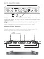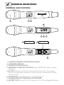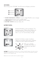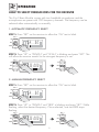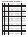
1
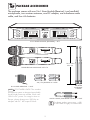
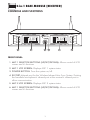
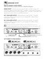
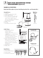
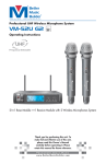
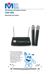
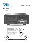
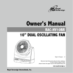
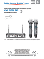
Better Music Builder .com
®
Passionate about Music
Professional UHF Wireless Microphone System
VM-92U G2
110421
Operating Instructions
UHF
Frequency Selectable
ON/OFF
ON/OFF
UHF WIRELESS SYSTEM VM-92U G2
MHz
DUAL CHANNEL RECEIVER
MIC 1
DOWN
UHF
2-IN-1 BASE RECEIVER MODULE
VM-92U G2
UP
725.000
B
SET
RF
AF
MHZ
CH FRQ SCAN IR
B
BAT
RF
AF
MHz
MIC 2
UP
750.000
iR
5mW
750.00
UHF WIRELESS SYSTEM VM-92U G2
5mW
725.00
MHZ
CH FRQ SCAN IR
SET
BAT
DOWN
POWER
2-in-1 Base Module ***1 Receive Module with 2 Wireless Microphones System
Thank you for purchasing this unit. To
make full and effective use of this unit,
please read this Owner's Manual
carefully before operating it. Please
retain this manual for future reference.
Passionate about Music
www.BetterMusicBuilder.com
CONTENTS
INTRODUCTION................................................................................ 1
Intro
SYSTEM FEATURES............................................................................. 1
Features
Package
Base Module
hand-held
Operation
PACKAGE ACCESSORIES................................................................... 2
2-in-1 BASE MODULE........................................................................ 3
• Controls and Functions................................................................. 3~4
• Hardware Setup.............................................................................5~6
HANDHELD MICROPHONE............................................................... 7
• Controls and Functions.................................................................. 7~8
OPERATION................................................................................. 9~13
• How to Select Frequencies for the Receiver................................... 9
• How to Match Receiver’s Frequency with Microphone............. 10
• How to Select Frequency/Channel for the Receiver................... 11
• How to Adjust Squelch.................................................................... 11
• How to Insert/change Batteries of Microphone.......................... 12
• How to Turn On/Off Microphone................................................. 13
• How to Interchange Microphone Head........................................13
TECHNICAL SPECIFICATION.............................................................14
Spec
BODY-PACK MICROPHONE (Optional)...................................... 15~16
Body-Pack
TROUBLESHOOTING................................................................. 17~18
Troubleshooting
APPENDIX................................................................................. 19~21
Appendix
WARRANTY..................................................................................... 22
Warranty
CONTACT INFORMATION............................................................... 23
Contact Us
INTRODUCTION
Intro
Better Music Builder VM-92U G2 is a second generation wireless microphone
that uses the latest UHF wireless technology. It is a heavy duty design which
includes two hand-held microphones with one 2-in-1 Base Module, built-in LCD
panel on both microphones and base units, solid built aluminum alloy handles,
and Wireless Infrared Auto Sync System.
The exceptional use of dual 2-in-1 Base Module allows for the use of two
channels to be on at one time improves signal quality and noise interference
prevention. Each hand-held microphone has 100 selectable channels. The two
microphones together have a total of 200 channels in the 725.000 MHz to
774.750 MHz frequency range, which are authorized for UHF home use in the
United States by FCC.
The G2 Series built in dual LCD panels allowing user to actively monitor the
status of the system channel selections and microphone battery levels with clear
status RF (Radio Frequency) connection and sensitive AF (Audio Frequency) input
signal indicators. The super bring backlight LCD allows user to dim light setting,
in turn, giving the owner full control and maintenance of the microphone system
day and nights.
It comes with easy and convenient portable mounting rack for rental system
usage, making this system a perfect use by Professional DJ and System Rental,
KTV clubs, restaurants, coffee shops and churches, etc.
Features
SYSTEM FEATURES
1. Equipped with the latest wireless technology and UHF dual-channel
in a 2-in-1 Base Module to pick up weak signals and prevent signal
interference.
2. Clear LCD screen displays Radio Frequency, Volume, Channel, and
Frequency.
3. Wireless Auto Sync System technology makes setting up a breeze.
4. Clear Voice technology delivers crystal clearer sound just like a wired
microphone.
5. 100 selectable channels!
6. Adjustable antennas for better signal receiving.
7. AA batteries for easy usage.
8. Left / Right squelch knobs.
1
PACKAGE ACCESSORIES
Package
The package comes with one 2-in-1 Base Module [Receiver], two handheld
microphones, two receiver antennas, one DC adaptor, one unbalance audio
cable, and four AA batteries.
DUAL CHANNEL RECEIVER
MIC 1
A
SET
DOWN
2-IN-1 BASE RECEIVER MODULE
UHF
VM-92U G2
UP
RF
AF
MHZ
750.000
CH FRQ SCAN IR
B
iR
BAT
RF
AF
750.000
CH FRQ SCAN IR
MIC 2
UP
MHZ
SET
BAT
DOWN
POWER
ON/OFF
ON/OFF
UHF WIRELESS SYSTEM VM-92U G2
5mW
MHz
5mW
MHz
725.00
UHF WIRELESS SYSTEM VM-92U G2
725.00
2-IN-1 BASE MODULE [RECEIVER]: 1 SET
10.2 inches
25.8 cm
HANDHELD MICROPHONE: SET of 2
ALKALINE
BATTERY
ALKALINE
BATTERY
AA
ALKALINE
BATTERY
AA
AA
ALKALINE
BATTERY
AA
AA (1.5V) BATTERY: 4 UNITS
RECEIVER
ANTENNA:
2 UNITS
DC POWER ADAPTOR: 1 UNIT
NOTE DC-POWER USAGE: This wireless
microphone system is designed specifically
for the North American market, which uses
120V for DC power. For usage in Asia or
Europe, please change it to 220V by an
adaptor with DC 14V output 500mA.
AUDIO CABLE (FOR MIXED OUTPUT): 1 UNIT
Recommend
2
For better quality connections, a XLR
to XLR cable is highly recommended.
Base Module
2-in-1 BASE MODULE [RECEIVER]
CONTROLS AND FUNCTIONS
DUAL CHANNEL RECEIVER
MIC 1
2-IN-1 BASE RECEIVER MODULE
UHF
MIC 2
VM-92U G2
UP
A
SET
RF
DOWN
AF
MHZ
750.000
CH FRQ SCAN IR
B
iR
BAT
RF
AF
UP
MHZ
750.000
CH FRQ SCAN IR
SET
BAT
DOWN
POWER
1
2
3
4
5
6
FRONT PANEL:
1. MIC 1 SELECTOR BUTTONS (UP/SET/DOWN): Allows control of LCD
screen and it’s functions
2. MIC 1 LCD SCREEN: Displays MIC 1 system status.
3. POWER BUTTON: Turns the system on/off.
4. IR PORT: Infrared port for the Wireless Infrared Auto Sync System. Pointing
the handheld microphone’s infrared port at the receiver’s infrared port to
allow communication.
5. MIC 2 LCD SCREEN: Displays MIC 2 system status.
6. MIC 1 SELECTOR BUTTONS (UP/SET/DOWN): Allows control of LCD
screen and it’s functions
3
LCD PANEL:
After turning on the “POWER” button, LCD screen will display the following:
B
7
RF
AF
8
9
MHZ
750.000
CH FRQ SCAN IR
10 11
BAT
12 13 14 15
7. Antenna A/B: Displays the antenna in use.
8. Radio Frequency: Strength indicator of radio signal.
9. Audio Frequency: Strength indicator of incoming audio signal.
10. Channel & Select: Displays current channel & Selector for channel.
11. Frequency Select: Selects frequency.
12. Scan: Scans for microphone frequency.
13. Infrared Scan: Scans for microphone Infrared frequency.
14. Frequency: Displays current frequency.
15. Battery Status: Displays microphone battery status.
REAR PANEL:
AUDIO OUTPUT
®
Better Music Builder®
MIC 2 BALANCED
MIC 1 BALANCED
364130911000
Model No.: VM-92U G2
CALIFORNIA, UNITED STATES OF AMERICA
w w w . B e t t e r M u s i c B u i l d e r. c o m
ENGINEERED AND DESIGN IN U.S.A.
TRUE DIVERSITY
MIX
DC-POWER
DC 14V
MAX
MIN
MIC 1 SQUELCH
ANTENNA-A
21
22
23
ANTENNA-B
MAX
MIN
MIC 2 SQUELCH
MIC 1 & 2
UNBALANCED
16
17
18
19
20
16. ANTENNA-B: Connect the antennas to the BNC socket.
17. MIC 2 SQUELCH CONTROL: Distance coverage adjustment.
18. MIXED OUTPUT: unbalanced 1/4" audio output for MIC 1 & MIC 2.
19. MIC 2 BALANCED OUTPUT: balanced XLR audio output.
20. MIC 1 BALANCED OUTPUT: balanced XLR audio output.
21. POWER SUPPLY: Removable adapter with DC14~22V 500mA.
22. MIC 1 SQUELCH CONTROL: Distance coverage adjustment.
23. ANTENNA-A: Connect the antennas to the BNC socket.
4
HARDWARE SETUP
Set Up
HOW TO CONNECT AUDIO OUTPUT:
There are three rear outputs as shown in the below diagram:
MIXED OUTPUT is unbalanced audio output for MIC 1 & MIC 2 using 1/4”
connection. When using this output, MIC 1 and MIC 2 have to share a signal. To
produce different effects on each microphone, MIC 1 and MIC 2 need their own
signals which can be done by using XLR connections.
MIC 1 BALANCED OUTPUT is balanced audio output for MIC 1 using XLR
connection. When using this output, you can change MIC 1 effects without
affecting MIC 2 effects.
MIC 2 BALANCED OUTPUT is balanced audio output for MIC 2 using XLR
connection. When using this output, you can change MIC 2 effects without
affecting MIC 1 effects.
Recommend
We highly recommend using balanced XLR connections if the distance between the
microphone receiver and the mixer is more than 10 feet. The grounding of the balanced XLR
connection delivers better quality signal by reducing noise.
AUDIO OUTPUT
®
Better Music Builder®
ANTENNA-B
MAX
MIN
MIC 2 SQUELCH
MIC 2 BALANCED
MIC 1 BALANCED
364130911000
TRUE DIVERSITY
MIX
DC-POWER
MIC 1 & 2
UNBALANCED
DC 14V
MIXED OUTPUT
(MIC 1 & 2 UNBALANCE)
1
3
2
Model No.: VM-92U G2
CALIFORNIA, UNITED STATES OF AMERICA
w w w . B e t t e r M u s i c B u i l d e r. c o m
ENGINEERED AND DESIGN IN U.S.A.
MAX
MIN
MIC 1 SQUELCH
ANTENNA-A
MIC 1 BALANCED OUTPUT (BALANCED XLR)
MIC 2 BALANCED OUTPUT (BALANCED XLR)
MHz
5mW
UHF WIRELESS SYSTEM VM-92U G2
MIC 1 HANDHELD MICROPHONE
AUDIO OUTPUT
®
Better Music Builder®
ANTENNA-B
MAX
MIN
MIC 2 SQUELCH
UHF WIRELESS SYSTEM VM-92U G2
MIC 2 HANDHELD MICROPHONE
MIC 2 BALANCED
MIC 1 BALANCED
364130911000
TRUE DIVERSITY
MIX
DC-POWER
MIC 1 & 2
UNBALANCED
DC 14V
REAR VIEW
XLR
Balanced Input
ON/OFF
725.00
MHz
5mW
ON/OFF
725.00
UHF WIRELESS SYSTEM DIAGRAM:
Model No.: VM-92U G2
CALIFORNIA, UNITED STATES OF AMERICA
w w w . B e t t e r M u s i c B u i l d e r. c o m
ENGINEERED AND DESIGN IN U.S.A.
MAX
MIN
MIC 1 SQUELCH
ANTENNA-A
BALANCED CONNECTION
XLR
Balanced Input
XLR
Balanced Input
XLR
Balanced Input
1/4"
1/4"
1/4"
1/4"
Unbalanced Input Unbalanced Input Unbalanced Input Unbalanced Input
AUDIO MIXER AMPLIFIER OR A KARAOKE UNIT INPUT TERMINAL
5
HOW TO CONNECT DC-POWER:
MIC 2 BALANCED
AUDIO OUTPUT
®
Better Music Builder®
MAX
MIN
MIC 2 SQUELCH
ANTENNA-B
MIC 1 BALANCED
Model No.: VM-92U G2
364130911000
TRUE DIVERSITY
MIX
DC-POWER
MIC 1 & 2
UNBALANCED
DC 14V
CALIFORNIA, UNITED STATES OF AMERICA
w w w . B e t t e r M u s i c B u i l d e r. c o m
ENGINEERED AND DESIGN IN U.S.A.
MAX
MIN
MIC 1 SQUELCH
ANTENNA-A
REAR VIEW
For North America Market, use 120V, DC 14~22V 500mA adaptor. For market
outside North America, use 220V~ 240V DC adaptor with a maximum battery
capacity of 500mA.
NOTE Please make sure to use the right DC adaptor. Otherwise, it may damage the 2-in-1 Base
Module and the charger because their maximum battery capacity is different. The product
warranty will be voided if there is damage caused by using the wrong DC adaptor.
OPTIONAL 19” RACK MOUNT KIT:
To put the system onto a mount-kit, please follow the diagram below. Our
special design feature allow it to be mounted on a DJ rack.
ANTENNA IS ADJUSTABLE
10 inches
DUAL CHANNEL RECEIVER
MIC 1
UHF
2-IN-1 BASE RECEIVER MODULE
VM-92U G2
UP
B
SET
DOWN
RF
AF
MHZ
725.000
CH FRQ SCAN IR
B
iR
BAT
RF
AF
CH FRQ SCAN IR
MIC 2
B
SET
DOWN
DOWN
POWER
UHF
RF
AF
MHZ
725.000
CH FRQ SCAN IR
B
iR
BAT
RF
POWER
13.8 inches
19 inches
Rack mount kit is not included in package.
6
2-IN-1 BASE RECEIVER MODULE
VM-92U G2
UP
SET
BAT
DUAL CHANNEL RECEIVER
MIC 1
UP
MHZ
750.000
AF
CH FRQ SCAN IR
MIC 2
UP
MHZ
750.000
SET
BAT
DOWN
HANDHELD MICROPHONE
Hand-held
ON/OFF
2
3
5mW
MHz
725.00
CONTROLS AND FUNCTIONS
1
UHF WIRELESS SYSTEM VM-92U G2
MHz
725.00
5mW
AA
6
7
ALKALINE
BATTERY
ON/OFF
ALKALINE
BATTERY
LEVEL
L
5
AA
H
iR
SET
MHz
5mW
ON/OFF
725.00
4
8
1. INTERCHANGEABLE MICROPHONE HEAD
2. LCD DIGITAL DISPLAY
3. POWER ON/OFF BUTTON
4. FREQUENCY SELECTION BUTTON: Press UP/DOWN button to select
frequency.
5. IR PORT: Infrared port for the Wireless Infrared Auto Sync Technology.
Point the microphone’s infrared port at the receiver’s infrared port to allow
communication.
6. SET BUTTON: Press SET button to confirm frequency.
7. TRANSMISSION POWER LEVEL CONTROLLER
8. BATTERY SLOTS: Insert 2x1.5V AA battery or 2x1.2V rechargeable battery.
7
LCD PANEL:
After turning on the “POWER”, the LCD screen will light up as below:
5mW
1
10mW
725.00
2
MHz
3
1. RADIO FREQUENCY SIGNAL: Switch to High (10mW) to use a stronger
signal and Low (5mW) to use a weaker signal.
2. FREQUENCY: Current value depends on your setting.
3. BATTERY STATUS: Indicates battery life.
BATTERY STATUS:
Full Battery
5mW
10mW
725.00
MHz
Indicates full battery on the microphone. The
engineering team of Better Music Builder uses
the latest technology to indicate the battery
status, so you can see the battery strength.
Low Battery
5mW
10mW
725.00
Indicates low battery on the microphone.
When the microphone LCD screen is blinking
or fading, its time to replace the batteries.
LCD screen will blink
constantly when battery is
extremely low and about
to die.
MHz
5mW
725.00
MHz
NOTE
If the microphone cannot be turn on, please check the battery. It may be very low.
Typical new full battery life is 4~6 hours with our system, otherwise, the batteries might be
defective or near expiration date.
Batteries are not covered under our product warranty.
8
OPERATION
Operation
HOW TO SELECT FREQUENCIES FOR THE RECEIVER
The 2-in-1 Base Module comes with two handheld microphones and the
microphones are preset with 100 frequency channels. The frequency can be
selected either automatically or manually.
1. AUTOMATIC FREQUENCY SELECT
STEP 1: Press “SET” on the receiver to allow the “CH” text to blink.
MIC 1
UP
A
SET
RF
DOWN
AF
MHZ
CH ----00
CH FRQ SCAN IR
BAT
STEP 2: Press “UP” or “DOWN” until “SCAN” is blinking and press “SET”. This
will allow the receiver search for the strongest frequency to set.
MIC 1
MIC 1
UP
A
SET
RF
DOWN
AF
UP
MHZ
725.000
CH FRQ SCAN IR
SET
BAT
DOWN
2. MANUAL FREQUENCY SELECT
STEP 1: Press “SET” on the receiver to allow the “CH” text to blink.
MIC 1
UP
A
SET
RF
DOWN
AF
MHZ
CH ----00
CH FRQ SCAN IR
BAT
STEP 2: Press “UP” or “DOWN” until “FRQ” is blinking and press “SET”. While
flashing, select the desired frequency. Once selected, wait until FRQ stops
flashing.
MIC 1
MIC 1
UP
A
SET
DOWN
RF
AF
UP
MHZ
725.000
CH FRQ SCAN IR
SET
BAT
DOWN
9
HOW TO MATCH RECEIVER’S FREQUENCY WITH MICROPHONE
STEP 1: Press “SET” on the receiver to allow the “CH” text to blink.
MIC 1
UP
A
SET
RF
DOWN
AF
MHZ
CH ----00
CH FRQ SCAN IR
BAT
STEP 2: Press “UP” or “DOWN” until “IR” is blinking and press “SET”.
MIC 1
MIC 1
UP
A
SET
RF
DOWN
AF
UP
MHZ
750.000
CH FRQ SCAN IR
SET
BAT
DOWN
STEP 3: While the “IR” light is on, turn ON the microphone, open battery
compartment and point the microphone infrared port (IR) directly at the
receiver’s IR PORT to initiate the syncing process.
MICROPHONE AND RECEIVER
FREQUENCY MATCHED
DUAL CHANNEL RECEIVER
MIC 1
5mW
10mW
725.00
MHz
UHF
2-IN-1 BASE RECEIVER MODULE
VM-92U G2
UP
A
SET
DOWN
RF
AF
MHZ
725.000
CH FRQ SCAN IR
B
iR
BAT
RF
AF
CH FRQ SCAN IR
MIC 2
UP
MHZ
750.000
SET
BAT
DOWN
POWER
MIC 2
iR
B
5mW
725.00
MHz
RF
ON/OFF
AF
UP
MHZ
725.000
CH FRQ SCAN IR
SET
BAT
DOWN
iR
SET
L
LEVEL
H
iR
Matching Frequencies
Distance: 3-inch
SET
L
LEVEL
H
IMPORTANT: IR should be visible to
the receiver. Twist battery cover off if
frequencies are not synching.
Please make sure that the other handheld microphone is turned off when adjusting the
NOTE
frequency on one microphone.
Each unit is fully tested and qualified by the manufacturer. However, due to the nature of wireless
connection, interference may occur because of local environments and/or radio signals emitted
by other wireless devices within the household.
10
HOW TO SELECT FREQUENCY/CHANNEL FOR THE RECEIVER
Frequencies can be recorded by finding the channel of the frequency. To do so;
STEP 1: Press “SET” on the receiver to allow the “CH” text to blink. Once
blinking press “SET” again, the frequency’s channel will be displayed on a
range of 0~99.
MIC 1
MIC 1
UP
A
SET
RF
DOWN
AF
UP
MHZ
CH ----00
CH FRQ SCAN IR
SET
BAT
DOWN
If you need to find a channel for a frequency not selected, please follow steps for
NOTE
“Manual Frequency Select” then follow step 1 for “:Frequency/Channel Select”).
HOW TO ADJUST SQUELCH
The SQUELCH knob on the back of the receiver adjusts the distance range
between the microphone and the receiver. Use a plastic screwdriver to make the
squelch adjustment at the button. A higher level of squelch allows the usage of
microphone further away from the receiver. However, the drawback of using a
higher level of squelch is the increased chance of interference.
AUDIO OUTPUT
®
Better Music Builder®
ANTENNA-B
MAX
MIN
MIC 2 SQUELCH
MIC 2 BALANCED
MIC 1 BALANCED
364130911000
TRUE DIVERSITY
MIX
DC-POWER
MIC 1 & 2
UNBALANCED
DC 14V
Model No.: VM-92U G2
CALIFORNIA, UNITED STATES OF AMERICA
w w w. B e t t e r M u s i c B u i l d e r. c o m
ENGINEERED AND DESIGN IN U.S.A.
MAX
MIN
MIC 1 SQUELCH
ANTENNA-A
MAX
MIN
MIC 1 SQUELCH
PLASTIC SCREWDRIVER
11
HOW TO INSERT/CHANGE BATTERIES OF MICROPHONE
MHz
5mW
ON/OFF
725.00
STEP 1: Twist open battery cover.
UHF WIRELESS SYSTEM VM-92U G2
MHz
5mW
slots.
ON/OFF
725.00
STEP 2: Use one hand to hold onto the top of the Microphone, and the other
hand to slide 2x1.5V AA batteries into battery slot. Be careful not to drop
Microphone while inserting batteries.
ALKALINE
BATTERY
AA
Make sure to follow the polarity of the battery according to the battery
ALKALINE
BATTERY
Good
No Good
ALKALINE
BATTERY
AA
AA
AA
MHz
5mW
ON/OFF
725.00
STEP 3: Twist back battery cover.
UHF WIRELESS SYSTEM VM-92U G2
12
ALKALINE
BATTERY
ALKALINE
BATTERY
AA
HOW TO TURN ON/OFF MICROPHONE
TURN ON: Press the ON/OFF button and release it
immediately to turn ON the microphone. Microphone’s
LCD panel will display frequency, radio frequency and
battery status.
TURN OFF: Press and hold the power button for 3
seconds to turn OFF the microphone. Microphone’s LCD
panel will turn off.
MHz
ON/OFF
UHF WIRELESS SYSTEM VM-92U G2
After turning on the microphone’s power on, there might
be a need to adjust the frequency to match the receiver’s
frequency.
5mW
725.00
NOTE
If the microphone cannot be turn on, please check the battery. It may be very low.
Typical new full battery life is 4~6 hours with our system, otherwise, the batteries might be
defective or near expiration date.
HOW TO INTERCHANGE MICROPHONE HEAD
1
NOTE
Replacement parts (such as the
microphone head as shown on the
left) can be purchased from any of
our authorized dealers.
2
5mW
725.00
MHz
ON/OFF
UHF WIRELESS SYSTEM VM-92U G2
INTERCHANGEABLE
MICROPHONE HEAD
13
TECHNICAL SPECIFICATION
Spec
A. TECHNICAL FEATURE OF THE 2-IN-1 BASE MODULE:
1.
2.
3.
4.
5.
6.
7.
8.
9.
10.
11.
12.
13.
14.
15.
16.
Channel: 100 Channels (total 200 Channels)
Frequency Range: UHF 725~750 MHz
Signal to Noise Ratio: > 90dB
Total Harmonic Distortion: < 0.5%
Band Width: < 250kHz
Frequency Response: 30Hz~19kHz +/-3dB
Sensitivity: >100dB
Effective Use Range: >50M
Receiver Shell: EIA standard 1/2U
Receiving Sensitivity: 2.0µV
Audio Output Level: Unbalanced Out: 0~+/-400mV
Balanced Out: 0~+/-200mV
Power Supply: DC 14V~22V with 500mA~1000mA, AC 120V (For 220V,
you may need to change to a 220V~240V DC adaptor)
Consume Power: 5 Watts
Receiver Dimensions (WxHxD): 8.2 x 1.7 x 6 (inches)/20.9 x 4.2 x 15.2(cm)
Package Dimensions (WxHxD): 16.9 x 13.7 x 2.8 (inches)/42.8 x 34.7 x 7.2(cm)
Shipping Weight: 5.6 lbs / 2.5 kg
B. TECHNICAL FEATURE OF THE MICROPHONE:
1.
2.
3.
4.
5.
6.
7.
8.
Transmitter Power: 5mW or 10mW (Switchable)
Osillation Mode: PLL
Harmonic Radiation: ≤-60dBc
Frequency Stability: ±0.005%,at 0~50℃
Battery Voltage: 2 x AA 1.5V Alkaline Battery
Continuous Using: 8 Hours (GP) 2 x AA 1.5V Battery
Battery Type: 1800mA/h battery
Microphone Dimensions (WxH): 10.2 x 2.2 (inches) / 25.8 x 5.5 (cm)
C. THIS SYSTEM INCLUDES THE FOLLOW:
•
•
•
•
2-in-1 Base Module: 1 Set
Handheld Microphone: 2 Sets
Antenna: 2 Units
AA 1.5V Battery: 4 Units
• DC-Power Adaptor: 1 Unit
• Audio Cable: 1 Unit
• Instructional Manual: 1 Unit
14
Body-Pack
BODY-PACK MICROPHONE SYSTEM
SPECIFICATION (Optional)
NAMES & FUNCTION:
Body-Pack Microphone System (including Lavalier Mic. and Headset Mic.)
Outside Picture
1. Antenna
2. 4-pin Microphone Input Jack
3. LCD Digital Display
4. IR Port: Receives infrared beam
to synchronize frequencies. IR
when using multiple systems,
only one microphone port should
be exposed at a time
5. Battery Cover
6. Tie-Clip
7. Microphone Extension Jack
1
Side-face
Picture
2
3
4
Optional
5
6
7
Optional
Inside Picture
1. Power/Mute indicator
Lavalier Mic.
• Green: Ready
• Amber: Mute Open
• Flashing Red: IR is transmission in
process
• Glowing Red: Low battery power
• Pulsing Red: Battery dead
(microphone cannot be turned off
until batteries are changed)
1
(Accessories)
1/4” to mini 3-pin lavalier cable
2
2. Power ON/OFF/mute switch
Button: Press and hold the
microphone for 3 seconds to turn
power ON/OFF. Press and
release to mute or un-mute the
microphone.
3. Adjustment switch
4. Battery Slot
3
Optional
4
Headset Mic.
Optional
(Accessories)
1/4” to mini 3-pin lavalier cable
Body-pack Microphone Top View
Apical Panel
1. Antenna Jack
2. Power/Mute indicator
3. Power Switch
4. Microphone Input Jack
1
2
3
15
4
Optional
HOW TO INSERT BODY-PACK MICROPHONE BATTERIES
STEP 1: Open battery cover.
Good
STEP 2: Insert 2 AA batteries. 2
alkaline batteries are expected to
use for about 8 hours.
Make sure that you insert batteries
correctly, as shown in picture. When
the microphone body-pack light
glows red, the batteries should be
changed immediately.
AA
ALKALINE
BATTERY
1
ALKALINE
BATTERY
AA
2
CLOSE
AA
ALKALINE
BATTERY
OPEN
HOW TO WEAR BODY-PACK MICROPHONE
The microphone can be buckled to the belt or the guitar band. For best result,
the microphone should be pushed down until the belt is close to the base of
microphone.
B
A
MICROPHONE BODY-PACK
REAR VIEW
ADJUSTMENT GAIN
Three gain settings are available.
Choose the appropriate setting for your
instrument.
• MIC: for the microphone adjustment
• 0: Guitar with passive pickups
• -10: Guitar with active pickups
16
MICROPHONE BODY-PACK
REAR VIEW
TROUBLESHOOTING
Troubleshooting
CAUTION: Before troubleshooting any symptoms make sure the
equipments are in the “OFF” position.
1. SYMPTOM: NO SOUND COMING FROM MICROPHONE
A. CAUSE: There is no indication of signal.
a. Turn microphone to “OFF” position. Check if batteries are inserted correctly.
b. If batteries are inserted correctly, but there is no power, insert new batteries
c. Make sure the microphone and receiver are in the same channel
d. The volume may be turned to a low level.
B. CAUSE: The receiver is unpowered.
Make sure the power adapter is connected properly and there is power
coming from the power outlet.
C. CAUSE: There is no indication of AF signal.
Turn off the receiver and make sure it is properly connected to the mixer or
amplifier. If it is, slowly turn the volume higher.
D. CAUSE: There is no indication of RF signal.
If there is no indication of RF signal there may be interference between the
receiver and the microphone. Change the channel between the microphone
and receiver otherwise; Adjust the antenna of the receiver and/or move away
objects between receiver and the microphone .
2. SYMPTOM: ONE OR MORE OF THE MICROPHONE IS NOT WORKING,
CHECK THE SOLUTIONS FOR CAUSES A~D ABOVE.
3. SYMPTOM: RANDOM NOISE COMING OUT FROM MICROPHONE
CAUSE: There are interference within your area.
1. Change the channel between the microphone and receiver.
2. Stand further away from your speaker.
17
4. SYMPTOM: THE MICROPHONE SUDDENLY HAS NO SOUND AND THE
RECEIVER LCD LIGHT IS OFF.
Make sure the AC power adapter is securely plugged into the electrical outlet
and into the DC input connector on the rear panel of the receiver. Make sure
the AC electrical outlet works and is supplying the proper voltage.
5. SYMPTOM: THE MICROPHONE SUDDENLY HAS NO SOUND BUT THE
RECEIVER SHOWS RF SIGNAL.
CAUSE: The microphone out lead is damaged or disconnected.
To fix it, open the microphone head cover to check on the microphone out
lead and re-connect the wire by wielding. If it does not work, replace the
microphone out lead.
6. SYMPTOM: THE MICROPHONE DISTORTION LEVEL IS INCREASING
GRADUALLY.
CAUSE: The microphone batteries are running out.
Replace the microphone batteries.
7. SYMPTOM: POOR SIGNAL
CAUSE: When the 2-in-1 Base Module and microphone are placed in different
rooms made of concrete wall. This would cause poor signal.
Your audio equipment is close to the police, fire or radio stations. In this case,
a different frequency channel MUST be selected. Both the microphone and
the 2-in-1 Base Module must change to a matching frequency.
8. SYMPTOM: THE FREQUENCY OF THE MICROPHONE IS DIFFERENT
FROM THE 2-in-1 Base Module.
The microphone’s frequency must match with 2-in-1 Base Module’s frequency.
18
Appendix
APPENDIX
VM-92U G2 FCC FREQUENCY: 725.000~774.750 MHz
UHF Frequencies Available for Use for Home Electronics in North America
The RF radio frequencies used in the transmission of wireless information are
closely regulated in most countries including North America. A lot of countries
strictly enforce their regulations stating which RF frequencies are available for
use for certain device, so it can help limit the amount of radio frequency
interference in all wireless communications.
Please refer to the following table for MIC 1 and MIC 2 with available RF
frequencies. If the RF frequencies indicated in the following table are in conflicts
with the local wireless information law in your country, please switch to a
different product model or contact our technicians for advice.
FCC Information to User for Reference
This equipment is designed in compliance with the limits for a Class A digital
device pursuant to part 15 of the FCC Rules from the United States of America.
These limits are designed to provide protection against harmful interference
when the equipment is operated in public environment. This equipment
generates, uses, and can radiates radio frequency energy and, if not installed
and used in accordance with the instruction manual, may cause harmful
interference to radio communications. Operation of this equipment in a
residential area may cause harmful interference, so the user will have to correct
the interference at his/her own expense.
19
MICROPHONE 1 FREQUENCY: 725.000~749.750 MHz
CH
FREQUENCY
CH
FREQUENCY
CH
FREQUENCY
CH
FREQUENCY
1
725.000
26
731.250
51
737.500
76
743.750
2
725.250
27
731.500
52
737.750
77
744.000
3
725.500
28
731.750
53
738.000
78
744.250
4
725.750
29
732.000
54
738.250
79
744.500
5
726.000
30
732.250
55
738.500
80
744.750
6
726.250
31
732.500
56
738.750
81
745.000
7
726.500
32
732.750
57
739.000
82
745.250
8
726.750
33
733.000
58
739.250
83
745.500
9
727.000
34
733.250
59
739.500
84
745.750
10
727.250
35
733.500
60
739.750
85
746.000
11
727.500
36
733.750
61
740.000
86
746.250
12
727.750
37
734.000
62
740.250
87
746.500
13
728.000
38
734.250
63
740.500
88
746.750
14
728.250
39
734.500
64
740.750
89
747.000
15
728.500
40
734.750
65
741.000
90
747.250
16
728.750
41
735.000
66
741.250
91
747.500
17
729.000
42
735.250
67
741.500
92
747.750
18
729.250
43
735.500
68
741.750
93
748.000
19
729.500
44
735.750
69
742.000
94
748.250
20
729.750
45
736.000
70
742.250
95
748.500
21
730.000
46
736.250
71
742.500
96
748.750
22
730.250
47
736.500
72
742.750
97
749.000
23
730.500
48
736.750
73
743.000
98
749.250
24
730.750
49
737.000
74
743.250
99
749.500
25
731.000
50
737.250
75
743.500
100
749.750
20
MICROPHONE 2 FREQUENCY: 750.000~774.750 MHz
CH
FREQUENCY
CH
FREQUENCY
CH
FREQUENCY
CH
FREQUENCY
1
750.000
26
756.250
51
762.500
76
768.750
2
750.250
27
756.500
52
762.750
77
769.000
3
750.500
28
756.750
53
763.000
78
769.250
4
750.750
29
757.000
54
763.250
79
769.500
5
751.000
30
757.250
55
763.500
80
769.750
6
751.250
31
757.500
56
763.750
81
770.000
7
751.500
32
757.750
57
764.000
82
770.250
8
751.750
33
758.000
58
764.250
83
770.500
9
752.000
34
758.250
59
764.500
84
770.750
10
752.250
35
758.500
60
764.750
85
771.000
11
752.500
36
758.750
61
765.000
86
771.250
12
752.750
37
759.000
62
765.250
87
771.500
13
753.000
38
759.250
63
765.500
88
771.750
14
753.250
39
759.500
64
765.750
89
772.000
15
753.500
40
759.750
65
766.000
90
772.250
16
753.750
41
760.000
66
766.250
91
772.500
17
754.000
42
760.250
67
766.500
92
772.750
18
754.250
43
760.500
68
766.750
93
773.000
19
754.500
44
760.750
69
767.000
94
773.250
20
754.750
45
761.000
70
767.250
95
773.500
21
755.000
46
761.250
71
767.500
96
773.750
22
755.250
47
761.500
72
767.750
97
774.000
23
755.500
48
761.750
73
768.000
98
774.250
24
755.750
49
762.000
74
768.250
99
774.500
25
756.000
50
762.250
75
768.500
100
774.750
21
WARRANTY
Warranty
One-Year Limited Warranty for Home Use Equipment
Our one-year warranty applies to speakers, amplifiers, mixers and microphones for
home use only. It covers both parts and labors. The warranty becomes effective on
the date of your purchase.
Our warranty only covers defects due to product defectiveness with free of defects
in materials or workmanship. However, our warranty does not cover defects due to
normal wears, damage in transit, improper use, abuse or failure to follow the proper
instructions for maintenance. This warranty is void in the event of unauthorized
repairs, alternations, modifications and removing of the product label.
Please also note that our warranty does not cover any shipping cost for the return of
defective products to us for inspection, repair and maintenance. Our warranty for
Better Music Builder products can only be executed in North America.
NOTE
Our warranty does not cover the battery for wireless microphone products.
90-Day Limited Warranty for Public and Commercial Use Equipment
Our 90-day warranty applies to speakers, amplifiers, mixers and microphones for
both public and commercial use such as restaurant, coffee shop, KTV nightclub,
church and school, etc. It covers both parts and labors. The warranty becomes
effective on the date of your purchase.
To Register Your Warranty
Please submit the warranty card that cames with your unit; it is also download on
our website . However, we need the invoice for your purchase in order to process
this warranty. You may also register your warranty online.
Please visit our website at w w w.B et terM usic B uil d er.com.
PRECAUTION
1. If using more than one microphone system, please select the operating
frequency or signal channel carefully so as to avoid disturbing.
2. The input power voltage of the 2-in-1 Base Module is 110V/120V (±10%). If it is
too low or too high, it will affect the work of the machine.
3. When installing batteries, reversing the electrode will damage the machine.
RISK OF ELECTRIC SHOCK
DO NOT OPEN
Caution: To reduce the risk of electrical shock, do not
remove the cover (or back). No user serviceable parts
inside: refer servicing to qualified personnel.
Warning: To reduce the risk of fire or electrical shock,
do not expose this appliance to rain or moisture.
22
This symbol, wherever it appears, alerts
you to the presence of uninsulated
dangerous voltage inside the enclosure
voltage that may be sufficient to
constitute a risk of shock.
This symbol, wherever it appears, alerts
you to important operating and
maintenance instructions in the
accompanying literature. Read the
manual.
CONTACT INFORMATION
Contact Us
MAILING ADDRESS
BETTER MUSIC BUILDER
29300 Kohoutek Way #150
Union City, CA 94587
U.S.A.
TELEPHONE NUMBERS
USA Region
USA Toll Free: 1-800-318-2218
Sales & Marketing: 510-477-9955
Customer Service: 510-477-9955
FAX NUMBERS
USA Region
Sales & Marketing: 510-477-9922
Customer Service: 510-477-9922
WORLD WIDE WEB
E-mail: [email protected]
Website: www.bettermusicbuilder.com
23
MAINTENANCE
NOTE
24
MAINTENANCE
NOTE
25
Better Music Builder® is a leader in the Audio
and Karaoke equipment industry. We are
committed to offering you high quality audio
products. Unlike any others brand, we
deliver the best cost and value to you directly.
For the latest update information including
operation manuals, installation instructions,
hook-up diagram and other new technologies updates etc. please visit us at our
website w w w. B e t t e r M u si c B uil d e r.c o m.
®
Passionate about Music
www.BetterMusicBuilder.com
364130911000
Code: 20130921
Printed on 100% Recycled Paper Comments E-mail to [email protected] Copyright © 2014 Better Music Builder. All rights reserved. Legal trademark.