1
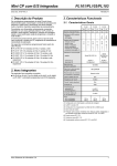
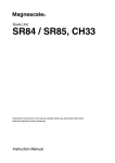
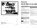
M: Machine guide B 200 or less B 4±0.2 A PL101 Head unit M Reference point mark Yaw: ±0.2° Reference point position Effective length 20 12 ID hole (for inserting parallel pin) (21) 0.16 25 Roll: ±0.2° 9 0.08 0.05 SL700/SL710 Scale 0.05 Head with Interpolator PL101-RM / PL101-RHM (20) Total length = Effective length + 40 12.65 Instruction Manual 1.5 6 Pitch: ±0.1° I4.4 A A 0.35±0.1 Clearance 0.08 43.5 11.5 Center mark 6.65 300 Cable length 48 Read all the instructions in the manual carefully before use and strictly follow them. Keep the manual for future references. PL101-R 3000 Cable length PL101-RH Safety Precautions 2 × 2-M3 Depth: 5 2-I 4.2 Interpolator 300 Ho le (39.8) 500 9 (11) (22.7) I8.5 110 101 11 8.4 t = 0.8 15.2 11 18.3 17.4 9.7 28 I4.4 9 Connector pin assignment 36210-0100PL (Sumitomo 3M Limited) 36310-3200-008 (Sumitomo 3M Limited) 1 +5 V 6 2 0V 7 3 SD / RD 8 4 XSD / XRD 9 5 10 Magnescale Co., Ltd. products are designed in full consideration of safety. However, improper handling during operation or installation is dangerous and may lead to fi re, electric shock or other accidents resulting in serious injury or death. In addition, these actions may also worsen machine performance. Therefore, be sure to observe the following safety precautions in order to prevent these types of accidents, and to read these “Safety Precautions” before operating, installing, maintaining, inspecting, repairing or otherwise working on this unit. Warning Indication Meanings The following indications are used throughout this manual, and their contents should be understood before reading the text. Unit: mm Warning Failure to observe these precautions may lead to fire, electric shock or other accidents resulting in serious injury or death. Caution Operating Cautions • Do not open the cover of this device or put your hand inside. Otherwise the internal circuit may be broken by static electricity. • This device is not explosion-proof. Do not use it in the atmosphere of flammable gas. • This device is not vibration resistant. Do not use it in place where it is subject to shocks. (Excluding the head unit) General precautions When using Magnescale Co., Ltd. products, observe the following general precautions along with those given specifically in this manual to ensure proper use of the products. • Before and during operations, be sure to check that our products function properly. • Provide adequate safety measures to prevent damages in case our products should develop malfunctions. • Use outside indicated specifications or purposes and modification of our products will void any warranty of the functions and performance as specified of our products. • When using our products in combination with other equipment, the functions and performances as noted in this manual may not be attained, depending on operating and environmental conditions. Failure to observe these precautions may lead to electric shock or other accidents resulting in injury or damage to surrounding objects. Warning • Do not use this unit with voltages other than the specified supply voltage as this may result in fire or electric shock. • Do not perform installation work with wet hands as this may result in electric shock. • Do not disassemble or modify the unit as this may result in injury or damage the internal circuits. Caution • Be sure to check the machine and device conditions to ensure work safety before working on the machine. • Be sure to cut off the power supply, air and other sources of drive power before working on the machine. Failure to do so may result in fire or accidents. • When turning on the power supply, etc. to operate the machine, take care not to catch your fingers in peripheral machines and devices. Shinagawa Intercity Tower A-18F, 2-15-1, Konan, Minato-ku, Tokyo 108-6018, Japan PL101-RM / PL101-RHM 2-A00-056-1A 2011.4 Printed in Japan ©2011 Magnescale Co., Ltd. [For U.S.A. and Canada] THIS CLASS A DIGITAL DEVICE COMPLIES WITH PART15 OF THE FCC RULES AND THE CANADIAN ICES-003. OPERATION IS SUBJECT TO THE FOLLOWING TWO CONDITIONS. (1) THIS DEVICE MAY NOT CAUSE HARMFUL INTERFERENCE, AND (2) THIS DEVICE MUST ACCEPT ANY INTERFERENCE RECEIVED, INCLUDING INTERFERENCE THAT MAY CAUSE UNDERSIGNED OPERATION. C E T A P PA R E I L N U M É R I Q U E D E L A C L A S S E A EST CONFORME À LA NORME NMB-003 DU CANADA. 4. Introduction This product set consists of the PL101-R/PL101-RH head unit and the MJ832 interpolator, which supports the Mitsubishi Electric Corporation serial protocol. This set is used in combination with the SL700/SL710 scale (sold separately). System Configuration 5. 6. Insert the supplied spacer between the head unit detection surface and the scale, and then mount the head unit and secure in place using M3 screws. The tightening torque should be 0.6 to 0.8 N.m. After mounting the head unit, remove the spacer. Check the relative positions of the scale and head unit. (See the figure below.) PL101-RM Scale SL700/ SL710 Yaw: ±0.2° mm PL101-R MJ832 Head unit Interpolator PL101-RH MJ832 Serial communication Mitsubishi Electric Corporation servo amplifier Offset: ±0.2 mm Pitch: ±0.1° Roll: ±0.2° PL101-RHM Clearance Offset Change Pitch Yaw in attitude Roll 0.35 ±0.1 mm ±0.2 mm ±0.1° ±0.2° ±0.2° Clearance: 0.35 ±0.1 mm Usage Notes Interpolator • Do not place objects that generate strong magnetic fields in the vicinity of this product. This could harm the accuracy of the scale. • This product should be used within an ambient temperature range of 0 to +45 °C, and should not be exposed to direct sunlight or heat sources. • During operation, be sure to keep the unit 0.5 m or more away from large power relays, high voltage or large current switches, or other sources of noise. • Wire the head cable and output cable separately from power lines. • When coupling relays, solenoids, motors or other devices to this unit, be sure to take measures to prevent noise. • Although the connection cable (for extension, sold separately) has been designed with sufficient durability for normal operating conditions, be careful not to apply excessive stress to the cable. This could severely harm the durability of the cable. • Make sure that the external magnetic field does not exceed 0.5 mT. The MJ832 interpolator is an incremental serial bidirectional signal (compliant with EIA-485) interpolator that supports the Mitsubishi Electric Corporation serial protocol. For information on supported Mitsubishi Electric Corporation servo amplifiers, contact your Magnescale Co., Ltd. sales representative. Notes • This interpolator does not support multi point and reference mark. • Connect a ground wire to the surface on which the interpolator will be installed. Failure to make a ground connection may result in worsened noise resistance. Head unit Head Unit Installation Procedure Count Direction Preparation • First, install the scale. For the installation procedure, refer to the instruction manual for the scale. • Check the range and surface accuracy of the installation surface. • Check the accuracy of the mounting screw coordinates. • The M3 tap screws mounted on the case have a depth of 5 mm. Obtain screws with a suitable length according to the thickness of the mounting brackets. The fitting length of the screws should be 4 to 5 mm. 2. 3. Align the unit Magnescale marks on the scale and head unit so that they are facing the same direction. The head unit is inscribed with a center mark that serves as a guide to the signal detection position. Install so that the center mark is always within the effective length. Set the origin so that the center mark matches up with the center of the reference point mark on the scale. Head unit M3 Center mark Spacer Scale Magnescale mark Addition direction Subtraction direction Cable Extension Installation 1. When the head unit and scale are installed as shown below, head unit movement to the right is the subtraction direction, and to the left is the addition direction. 10 m or less Head unit 20 m or less Extension cable (sold separately) Mini-DIN8 pin plug Mini-DIN8 pin socket Model CK-T12 CK-T13 CK-T14 CK-T15 Mitsubishi Electric Corporation servo amplifier Interpolator Cable length 1m 3m 5m 10 m Extension cable (sold separately) Sumitomo 3M Limited 10-pin plug Sumitomo 3M Limited 10-pin receptacle Model CE33-1 CE33-3 CE33-5 CE33-10 CE33-15 CE33-20 Cable length 1m 3m 5m 10 m 15 m 20 m Specifications Head unit Interpolator Output interface Supported scales Reproduced wavelength Resolution (Number of divisions) Accuracy (at 20 °C) Reference point detection function Reference point detection conditions Supply voltage Current consumption Inrush current PL101-RM PL101-RHM PL101-R PL101-RH MJ832 Mitsubishi Electric Corporation serial communication specifications Incremental serial bidirectional signal, compliant with EIA-485 SL700, SL710 series 800 μm 0.1 μm (1/8000) PL101-RM PL101-RHM 610 ms max. after power-on (When the power supply rise time is 10 ms) 10 m/s 0.5 mT max. System startup time Maximum response speed External magnetic field strength Vibration resistance Impact resistance Maximum cable length Cable length Protection class (Excluding the connector and interpolator) Mass (Head unit) Mass (Interpolator) Operating temperature and humidity range Storage temperature and humidity range Accessories Differs according to the scale length1 Included Bidirectional, maximum detection speed 10 m/s DC 5 V ±5% 200 mA Max. 2 A max. (When the power supply rise time is 10 ms) 20 m/s2 (50 Hz to 2 kHz) 980 m/s2 (11 ms) See “Cable Extension.” Refer to the dimensional diagrams. IP50 or IP67 or equivalent equivalent 60 g 150 g 100 g 0 to 45 °C (No condensation) –20 to 50 °C (90% RH max.) Spacer, instruction manual 1 Accuracy (at 20 °C) L 3000 mm Accuracy: ±10L μm According to the combination with the PL101 Accuracy measured at 20 °C at the time of manufacturing L : Effective length (1 m unit integer) N : Integer corresponding to the length L 3000 mm See Table 1 Accuracy : ± (10L + 2.5N) μm Table 1: Relationship between Effective Length (L) and N L (m) 3 5.5 8 10.5 13 15.5 18 20.5 23 25.5 L L L L L L L L L L 5.5 8 10.5 13 15.5 18 20.5 23 25.5 28 N 1 2 3 4 5 6 7 8 9 10 L (m) 28 30.5 33 35.5 38 40.5 43 45.5 48 50.5 L L L L L L L L L L 30.5 33 35.5 38 40.5 43 45.5 48 50.5 53 N 11 12 13 14 15 16 17 18 19 20 L (m) 53 55.5 58 60.5 63 65.5 68 70.5 73 75.5 L L L L L L L L L L 55.5 58 60.5 63 65.5 68 70.5 73 75.5 78 N 21 22 23 24 25 26 27 28 29 30 L (m) 78 80.5 83 85.5 88 90.5 93 95.5 98 L L L L L L L L L 80.5 83 85.5 88 90.5 93 95.5 98 100 N 31 32 33 34 35 36 37 38 39