1
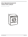
Coin- Operated Commercial
Tumble Action Washer
Installation Instructions and
Use and Care Guide
P/N 134778000 (0706)
Made in USA
TABLE OF CONTENTS
Important Safety Instructions..........................................3
Pre-Installation Requirements.......................................4
Electrical Requirements.................................................4
Grounding Requirements..............................................4
Water Supply Requirements..........................................4
Drain Requirements........................................................4
Location Of Your Washer...............................................4
Rough-In Dimensions....................................................5
Before beginning installation, carefully read
these instructions. This will simplify the
installation and ensure the washer is
installed correctly and safely. Leave these
instructions near the washer after
installation for future reference.
NOTE: The electrical service to the washer
must conform with local codes and
ordinances and the latest edition of the
National Electrical Code, ANSI/NFPA 70.
NOTE: The instructions appearing in this
INSTALLATION AND SAFETY INSTRUCTIONS
manual are not meant to cover every possible
condition and situation that may occur. Common
sense and caution must be practiced when
installing, operating and maintaining any
appliance.
Unpacking.......................................................................6
Installation..................................................................6-7
Coin slide installation................................................7-9
Meter case instructions.................................................9
Replacement Parts..........................................................10
Parts lists....................................................................10-11
Warranty.........................................................................12
Product Record
For Frigidaire warranty information or to contact a Frigidaire
Service Center, call 1-866-738-1640
If you need SERVICE or PARTS for your Frigidaire coinoperated dryer: be ready to give the model number, serial
number and date of purchase. Record below.
Model number________________________________________
Serial number_________________________________________
Purchase date_________________________________________
Record Coin Box
Key Number__________________________________________
Key number is on key and/or coin box.
WASHER SAFETY
Your safety and the safety of others is very important. We have provided many important safety messages in the
Instructions/Use & Care Guide and on your appliance. Always read and obey all safety messages.
Installation
This is the safety alert symbol. This symbol alerts you to hazards that can kill or hurt you or others. All safety messages will be
preceded by the safety alert symbol and the word "DANGER" or "WARNING". These words mean:
DANGER You can be killed or seriously injured if you don't immediately follow instructions.
You can be killed or seriously injured if you don't follow instructions.
All safety messages will identify the hazard, tell you how to reduce the chance of injury, and tell you what can happen if the
instructions are not followed.
For your safety the information in this manual must be followed to minimize the risk of fire or explosion or to prevent
property damage, personal injury or loss of life.
- Do not store or use gasoline or other flammable vapors and liquid in the vicinity of this or any other appliance.
- WHAT TO DO IF YOU SMELL GAS
· Do not try to light any appliance.
· Do not touch any electrical switch; do not use any phone in your building.
· Clear the room, building or area of all occupants.
· Immediately call your gas supplier from a neighbor’s phone. Follow the gas suppliers instructions.
· If you cannot reach your gas supplier, call the fire department.
Installation and service must be performed by a qualified installer, service agency or the gas supplier.
Your washer is equipped with a door safety interlock. Verify proper operation of interlock system daily, using the following procedure:
1. With the washer door open, insert the required number of coins and press the START button. THE WASHER MUST NOT START!
2. Close the washer door. Press the START button again to start the machine. Attempt to open the door, without exerting excessive
force. THE DOOR MUST NOT OPEN!
IF THE WASHER STARTS WITH THE DOOR OPEN, OR THE DOOR CAN BE OPENED WHILE THE WASHER IS OPERATING, THE
MACHINE MUST IMMEDIATELY BE TAKEN OUT OF SERVICE. DISCONNECT THE POWER CORD, AND MARK THE MACHINE "OUT
OF ORDER", UNTIL THE INTERLOCK SYSTEM IS REPAIRED, AND
2 OPERATES AS DESCRIBED ABOVE.
Avoid fire
hazard or electrical shock.
Do not use an adaptor plug
or extension cord or
remove grounding prong
from electrical power cord.
Failure to follow this
warning can cause serious
injury, fire or death.
Grounding
type
Grounding
wall receptacle
type wall receptacle
Do not under
Do
under any
anynot
circumstances
circumstances
cut, remove,
cut, remove,
bypass the grounding
or bypass
the
grounding
prong
prong
from this plug.
from this plug.
Power
supply
Power
supply
cord with
cord with 3-prong
3-prong
grounding
grounding
plug plug
CORRECT Use this way ONLY
Important Safety Instructions
Do not use or mix
liquid chlorine bleach with
other household chemicals
such as toilet cleaners, rust
removers, acid or products
containing ammonia. These
mixtures can produce
dangerous fumes which can
cause serious injury or death.
Read all instructions before using this washer.
You can be killed or seriously injured if you don't follow these Important Safety Instructions:
• To reduce the risk of fire, electrical shock, or injury to persons when using this washer, comply with the basic warnings listed below.
• Failure to comply with these warnings could result in serious personal injuries.
Prevent Fire
• Do not wash items that have been previously cleaned in, soaked in, or spotted with gasoline, cleaning solvents, kerosene, cooking
oils, waxes, etc. Do not store these items on or near the washer. These substances give off vapors or chemical reactions that could
ignite or explode.
• Do not put oily or greasy rags or clothing on top of the washer. These substances give off vapors that could ignite the materials.
• Do not add gasoline, cleaning solvents, or other flammable or explosive substances to the wash water. These substances give
off vapors that could ignite or explode.
FOR YOUR SAFETY Do not store or use gasoline or other flammable vapors or liquids in the vicinity of this or
any other appliance.
• Under certain conditions, hydrogen gas may be produced in a hot water system that has not been used for 2 weeks or more.
HYDROGEN GAS IS EXPLOSIVE. If the hot water system has not been used for such a period, before using the washer, turn
on all hot water faucets and let the water flow from each for several minutes. This will release any accumulated hydrogen gas.
Hydrogen gas is flammable; do not smoke or use an open flame during this time.
• Failure to comply with these warnings could result in fire, explosion, serious bodily injury and/or damage to the rubber or plastic
parts of the washer.
Protect Children
• Do not allow children to play on or in the washer. Close supervision of children is necessary when the washer is used near children.
As children grow, teach them the proper, safe use of all appliances.
• Destroy the carton, plastic bag and other packing materials after the washer is unpacked. Children might use them for play. Cartons
covered with rugs, bedspreads or plastic sheets can become airtight chambers.
• Keep laundry products out of children's reach. To prevent personal injury, observe all warnings on product labels.
• Before the washer is removed from service or discarded, remove the washer lid to prevent accidental entrapment.
• Failure to comply with these warnings could result in serious personal injuries.
Prevent Injury
• Test door interlock system daily. Follow instructions on previous page.
• To prevent shock hazard and assure stability during operation, the washer must be installed and electrically grounded by a qualified
service person in accordance with local codes. Refer to INSTALLATION AND SAFETY INSTRUCTIONS for detailed grounding
procedures. If the washer is moved to a new location, have it checked and reinstalled by a qualified service person.
• To prevent personal injury or damage to the washer, the electrical power cord of the washer must be plugged into a properly
grounded and polarized 3-prong outlet. The third grounding prong must never be removed. Never ground the washer to
a gas pipe. Do not use an extension cord or an adaptor plug.
• Follow package directions when using laundry products. Incorrect usage can produce poisonous gas--resulting in serious injury
or death.
- Do not combine laundry products for use in 1 load unless specified on the label.
- Do not mix chlorine bleach with ammonia or acids such as vinegar.
• To prevent serious personal injury and damage to the washer:
- All repairs and servicing must be performed by an authorized servicer unless specifically recommended in this
INSTALLATION AND SAFETY INSTRUCTIONS manual. Use only authorized factory parts.
- Do not tamper with controls.
- Do not install or store the washer where it will be exposed to the weather.
• To reduce the risk of electric shock, disconnect this appliance from the power supply before attempting any user maintenance.
Turning the controls to the OFF position does not disconnect this appliance from the power supply.
• To prevent injury, do not reach into the washer while parts are moving. Before loading, unloading or adding items, push in the cycle
selector knob and allow the tub to coast to a complete stop before reaching inside.
• Failure to comply with these warnings could result in serious personal injuries.
• This washer is equipped with an electrical overload protector. The motor will stop if it becomes overheated. The washer will
automatically restart after a cool down period of up to 30 minutes, if the washer has not been manually turned off during this time.
SAVE3THESE INSTRUCTIONS
3
DRAIN REQUIREMENTS
PRE-INSTALLATION REQUIREMENTS
1.
2.
3.
4.
5.
6.
7.
Models equipped with drain pump:
Tools Required for Installation:
1/4 in. nut driver
3/8 in. socket with ratchet.
3/8 in. open end wrench.
7/16 in. socket with ratchet.
9/16 in. open end wrench.
Channel-lock adjustable pliers.
Carpenter’s level.
1. Drain MUST be capable of eliminating 17 gals (64.3 L) per
minute.
2. A standpipe diameter of 1-1/4 in. (3.18 cm) minimum.
3. The standpipe height above the floor should be:
ELECTRICAL REQUIREMENTS
CIRCUIT - Individual, properly polarized and grounded 15 amp.
branch circuit fused with 15 amp. time delay fuse or circuit breaker.
POWER SUPPLY - 2 wire, with ground, 120 volt, single phase, 60
Hz, Alternating Current. NOTE: The use of this washer with power
created by gas powered generators, solar powered generators,
wind powered generators or and other generator other than the
local utility company is not recommended.
OUTLET RECEPTACLE - Properly grounded 3-prong receptacle to
be located so the power supply cord is accessible when the washer
is in an installed position. NOTE: GFI (Ground Fault Interrupter)
receptacle is not required.
Max.
NOTE:
Drain hose attached to the washer can reach a 58 in. (147 cm)
high standpipe. For higher standpipe use hose P/N 134592701,
available from an authorized parts distributor. If drain is less
than 24 in. (61 cm), install a siphon break kit, available at your
local hardware store.
Models equipped with gravity drain:
1. Floor drain MUST be capable of eliminating 17 gals (64.3 L)
per minute.
2. Floor drain diameter must be at least 1/2 inch larger than
drain hose.
GROUNDING REQUIREMENTS
Improper connection of the equipment grounding
conductor can result in a risk of electrical shock. Check with a
licensed electrician if you are in doubt as to whether the appliance
is properly grounded.
1. The washer MUST be grounded. In the event of malfunction
or breakdown, grounding will reduce the risk of electrical
shock by a path of least resistance for electrical current.
LOCATION OF YOUR WASHER
See rough-in dimensions on the next page (Figure 1).
2. Since your washer is equipped with a power supply cord
having an equipment-grounding conductor and a grounding
plug, the plug MUST be plugged into an appropriate, copper
wired receptacle that is properly installed and grounded in
accordance with all local codes and ordinances or in the
absence of local codes, with the National Electrical Codes,
ANSI/NFPA 70 (latest edition). If in doubt, call a licensed
electrician.
DO NOT cut off or alter the grounding prong on the power supply
cord. In situations where a two-slot receptacle is present, it is the
owner’s responsibility to have a licensed electrician replace it
with a properly grounded three prong grounding type
receptacle.
DO NOT INSTALL YOUR WASHER:
1. In an area exposed to dripping water or outside weather
conditions. The ambient temperature should never be below
60 degrees F (15.6 degrees C) for proper washer operation.
2. In an area where it will come in contact with curtains or
drapes.
3. In an area (garage or garage-type building) where gasoline
of other flammables are kept or stored (including
automobiles).
4. On carpet. Floor MUST be solid with a maximum slope of
1/2 in. per foot (1.27 cm per 30.5 cm). To ensure vibration or
movement does not occur, reinforcement of the floor may
be necessary.
WATER SUPPLY REQUIREMENTS
IMPORTANT MINIMUM INSTALLATION CLEARANCES
Hot and cold water faucets MUST be installed within 42 inches When installed in alcove: Sides, Rear, Top = 0 in (0 cm).
(107 cm) of your washer’s water inlet. The faucets MUST be 3/4 When installed in closet: Sides, Rear, Top = 0 in (0 cm),
inch (1.9 cm) garden hose type so inlet hoses can be connected. Front = 1 in (2.54 cm).
Water pressure MUST be between 10 and 120 pounds per square Closet door ventilation openings required: 2 louvers each 60 in ²
inch (maximum unbalance pressure, hot vs. cold, 10 psi.) Your (387 cm²) - 3 in (7.6 cm) from top and bottom of door.
water department can advise you of your water pressure.
4
4
ROUGH-IN DIMENSIONS
17
<
>
(43.2)
POWER
CORD
SIDE
inch (cm)
43/8
(11.2)
>
<
^ 8
(20.4)
v
UNDER
COUNTER
WATER
INLETS
Ñ
Ò
BACK
inch (cm)
(Figure 1).
55
UNPACKING
1. Cut the shipping carton along the dotted line along the base
of the unit.
2. While in the carton carefully lay the washer on its back
side.
3. Removethe styrofoam base.
4. Carefully return the washer to an upright position and remove
the carton.
5. Carefully move the washer to within 4 feet (122cm) of the
final location.
6. Remove the following from the back side of the washer:
3 bolts,
3 yellow plastic spacers,
2 or 3 metal "P" clamps.
9. Remove the large styrofoam block located under the drum.
Lift up on the drum, tilt the base of the foam block inwards
toward the rear of the washer until free, then pull it out.
10. Remove and discard the yellow ribbon and label from the
front of the washer.
11. From the rear of the washer, carefully pull out the power
supply cord through the hole in the backsheet.
12. Replace the service panel and screws.
NOTE: If the washer is to be transported at a later date, the
shipping support hardware must be reinstalled to prevent
shipping damage.
BOLT
SPACER
"P"
7.
INSTALLATION
CLAMP
1. Run some water from the hot and cold faucets to flush the
water lines and remove particles that might clog up the water
valve screens.
Remove the service panel from the front of the washer.
2. Remove the inlet hoses and rubber washers from the plastic
bag and install the rubber washers in each end of the inlet
hoses.
8. Remove the 4 nuts and 6 large washers that attach the 2
yellow shipping braces to the drum and the base. Lift up on
the drum and remove the braces (a yellow ribbon surrounds
the items to be removed). These braces must be removed to
allow the power supply cord to be released from the shipping
ring.
3. Carefully connect the inlet hose marked "HOT" to the outside
"H" outlet of the water valve. Tighten by hand, then tighten
another 2/3 turn with pliers. Carefully connect the other
inlet hose to the inside "C" outlet of the water valve. Tighten
by hand, then tighten another 2/3 turn with pliers. Do not
crossthread or over-tighten these connections.
4.
6
Connect the inlet hose ends to the HOT and
COLD water faucets tightly by hand, then
tighten another 2/3 turn with pliers. Turn the
water on and check for leaks.
11.Be sure you have read the "Important Safety Instructions"
before operating this washer.
5. On machines equipped with drain pump, form
a U shape on the end of the drain hose, with
the hose pointed toward the drain.
12.Run the washer through a complete cycle. Check for water
leaks and proper operation.
NOTE: If the drain hose is placed in a standpipe
without forming a U shape, a siphoning action
could occur. There must be an air gap around
the drain hose. A snug hose fit can also cause a
siphoning action.
13. Keep these instructions for future reference.
NOTE: A wiring diagram is located inside the washer on the
side panel.
COIN BOX ADJUSTMENT
The tight fit of the money box is set at the factory. Customer may
loosen fit as desired by loosening the slotted nuts. See FIG.2.
Cable
Tie
FIGURE 2
6. Carefully move the washer to its final location.
NOTE: Do not use the dispenser drawer or door to lift washer.
Excessive noise and vibration can be prevented by properly
leveling the washer.
Keep A record of all coin-box key numbers.
A lost key can only be replaced by ordering the key numbers from
the place were the unit was purchased. The key number is located
7. For free standing installation and with the washer in it’s final
both on the key and behind the end panel of the coin box. If the
position, place a level on top of the washer. Adjust the leveling
key number is not available, the lock must be drilled out to remove
legs so the washer is level front-to-rear and side-to-side, and
the coin box.
stable corner-to-corner.
Instructions for Changing Vend Price
TOOLS NEEDED
• Medium sized slotted screwdriver
• Small slotted Phillips screwdriver
Place all screws and other items removed from coin slide assembly
on a cloth so they will not get lost.
STEP 1
Remove slide mechanism from meter case. (see FUGURE 1).
Press down on alternate corners and sides and feel for the
slightest movement. Adjust the appropriate leg so the washer
is SOLID on the floor on ALL four legs. Keep the leveling leg
extension at a minimum for best performance of thewasher.
FIGURE 1
8. For pedestal installations, See additional installation
instructions included with the pedestal.
STEP 2
Remove the coin slide extension from coin slide by removing two
mounting screws and spacers
(2) Mounting Screws
(see FIGURE 2).
9. Models equipped with drain pump: Place the formed end
of the drain hose in a laundry tub or a standpipe and secure
with the cable tie provided in the enclosure package. NOTE:
The drain pipe or floor drain, into which the drain hose is placed,
MUST be at least 1/2 inch larger in diameter than the drain
hose. This will insure that the sewer line cannot back up into
the washing machine.
and Spacers
FIGURE 2
10.Plug the power cord into a grounded outlet.
NOTE: Check to ensure the power is off at the circuit breaker/
fuse box before plugging the power cord into an outlet.
10.Turn on the power at the circuit breaker/fuse box.
7
Slide Return Spring
STEP 3
Remove coin slide from coin chute:
• Unhook and remove the coin slide return spring. (see FIGURE 2).
• Turn coin slide mechanism upside down.
• Remove coin slide stop by taking out two screws to the chute bottom
(see FIGURE 3).
(2) Slide Stop
Screws
STEP 6
Set new vend price by adding or removing the appropriate
block-out keys and/or dime inserts according to th Table
of Vend Prices
(see FIGURE 7).
FIGURE 7
TABLE OF VEND PRICE
VEND
PRICE
FIGURE 3
COIN SLOTS
1 2 3 4 5 6 7 8
0
$.10
$.20
$.25
NOTE:
Black
colored
slots are
closed off
by blockout key.
• Pull coin slide out of coin chute (see FIGURE 4).
FIGURE 4
$.35
$.45
$.50
$.60
$.70
$.75
$.85
$.95
$1.00
$1.10
$1.20
$1.25
STEP 4
Turn coin slide upside down and remove screw that holds coin receiver
block (see FIGURE 5).
$1.35
$1.45
(1) Receiver Block Screw
$1.50
$1.60
$1.70
$1.75
$1.85
FIGURE 5
$2.00
To remove block-out keys, pull straight up.
Spare Parts
Compartment
and Screw
STEP 5
Remove coin receiver block from coin slide (see FIGURE 6):
NOTE: Be sure block-out keys and /or dime inserts are
seated properly and ratchet dog is in place with irs spring
connected (see FIGURE 8).
Be sure the proper coin sizing block is in place.
• Turn coin slide right side up. Keep coin receiver block in place with
your fingers.
Ratchet
Dog and
Spring
• Carefully lift coin slide from coin receiver block. If necessary, shake
coin slide gently to loosen block.
Block-Out
Keys
FIGURE 6
FIGURE 8
Coin Receiver
Block
8
8
Change coin sizing block:
• Remove two screws that hold upper coin chute cover.
Remove cover (see FIGURE 9).
FIGURE 9
(2) Upper Coin
Chute Cover
Screws
Anti-Cheat
Gate
Meter Case Instructions
INSTRUCTIONS TO CHANGE THE NUMBER OF COIN SLIDE
INSERTIONS TO START APPLIANCE.
1. Disconnect power from machine.
2. Remove meter-case service door. (Fig.1)
Remove
meter-case
service door
(2) Coin Sizing
Block Screws
Shaft and
cam
assembly
FIGURE 1
FIGURE 10
Coin Sizing
Block
3. Turn Shaft & Cam Assembly in a clockwise direction until switch
lever arm drops into cam notch (Fig. 2).
• Remove two screws that hold coin sizing block to upper
coin chute cover cover (see FIGURE 10).
• Put new coin sizing block in place. Reinsert and tighten
mounting screws.
• Replace coin chute cover. Reinsert and tighten screws.
4. Lift Adjusting Tab away from cam with finger and turn Tab to
desired number. Make sure Tab\ locks into place in new position.
STEP 7
Replace coin receiver block into slide:
• Hold coin receiver right side up in the palm of one hand.
• Lower coin slide until coin receiver block fits into the
coin slide cavity. CAUTION: Do not dislodge ratchet dog
and spring.
• Hold coin receiver block in place with your fingers and
turn slide upside down.
• Insert and tighten screw.
6. Replace meter-case service door and reconnect power to machine.
5. Turn Shaft & Cam Assembly in a clockwise direction until switch
lever arm is on top of Tab to assure that both mechanism switches
are open (Fig. 3).
EXAMPLE: To change from $1 to $2 move tab from 1 to 2.
FIGURE 2
USE FINGER
TO LIFT PAD
CA M NOTCH
ADJUSTMENT
TA B
STEP 8
Install slide into coin chute. Slide can only be pushed in if
the anti-cheat gate in flange is pushed to the left. (see
FIGURE 9).
E
CLOCKWISE
DIRECTION
7
STEP 9
Replace coin slide stop with two screws. Replace coin
slide return spring. Replace coin slide extension with two
screws (be sure spacers are in place).
TO LIFT
STEP 10
Replace coin slide mechanism in meter case. Replace and
tighten coin slide mounting bolt.
FIGURE 3
SWITCH LEVER ARM
NOTE: It may be easier to insert coin slide mounting bolt if
you remove the timer from the mounting screws temporarily.
7
9
9
FIGURE
REPLACEMENT PARTS
If replacement parts are needed for your dryer, contact the source where you purchased your dryer, or call Frigidaire at
1-866-738-1640. For coin box parts, call 1-800-221-0982, Greenwald Industries.
Destroy the carton and plastic bags after the washer is unpacked. Children might use them for play. Cartons covered
with rugs, bedspreads, or plastic sheets can become airtight chambers causing suffocation. Place all materials in a garbage container
or make materials inaccessible to children.
The instructions in this manual and all other literature included with this washer are not meant to cover every possible
condition and situation that may occur. Good safe practice and caution MUST be applied when installing,operating and maintaining
any appliance.
Maximum benefits and enjoyment are achieved when all the Safety and Operating instructions are understood and practiced
as a routine with your laundering tasks.
Parts List for series 7682 “Quick-Change” Start Mechanism
Item 27A: Models 76-1030-21 (115v-60Hz),
76-1030-22 (230v-60Hz)
Item 27B: Models 76-1030-11 (115v-60Hz),
76-1030-12 (230v-60Hz)
ITEM
1
2
3
4
5
6
7
8
9
10
11
12
13
14
15
16
17
REQ’D
2
1
1
1
1
1
3
2
1
1
1
1
1
1
1
1
1
PART NO
00-7185
76-6009-*
76-1037
76-5014
76-2033
00-8149
00-7070
76-5013
00-8003
76-1036
76-5017
76-2003
59-204
76-5012
76-5010
00-7055
00-7047
DESCRIPTION
#4-40 SELF-TAPPING SC.
TIMER MOTOR ASS’Y
SWITCH & BRACKET SUB-ASS’Y
DRIVE SELEEVE
SLEEVE
TORSION SPRING
RETAINING RING
DRIVE BUSHING
SPRING
RACTHET ARM & PAWL ASS’Y
RACHET WHEEL
WASHER
SPRING
CAM
ADJUSTER TAB
SPRING WASHER
WASHER
ITEM
18
19
20
21
22
23
24
25
26
27A
27B
28
29
30
10
10
REQ’D
1
2
2
1
1
1
1
1
2
1
1
1
1
1
PART NO
76-2026
00-7458
00-7097
00-6189
00-6190
76-5009
76-2035
76-6000
02-0810-00
76-2059
76-2027
59-0314
58-172-*
00-7558
DESCRIPTION
DRIVE SHAFT
#4-40 3/16 PAN HD SC.
#4 SPLIT LOCKWASHER
SNAP SWITCH
SNAP SW. & LEVER ARM ASS’Y
SWITCH INSULATOR
NUT PLATE
WIRE HARNESS ASS’Y
#8-32x5/16 SEMS SCREW
MOUNTING BRACKET
MOUNTING BRACKET
CABLE TIE
GROUND WIRE
WASHER
V8 Coin Chute Parts List
20-3020
20-3000
V8 Parts List
DESCRIPTION
REQ. 20-3020 20-3000
————————————————————————————
1 SCREW (METRIC)
2
00-9724
00-7924
————————————————————————————
2 SCREW (METRIC)
2
00-7938 00-7938
————————————————————————————
3 TOP HOUSING
1
20-3019 20-3002
————————————————————————————
4 SHIM
2
20-2042 ----------————————————————————————————
5 COIN SIZING BLOCK
1
20-3006 20-3006
————————————————————————————
6 GATE COVER
1
20-2043 20-2006
————————————————————————————
7 GATE
1
20-2035 20-2000
————————————————————————————
8 SLIDE STOP DOG
8
20-2011 20-2011
————————————————————————————
9 DOG SHAFT
1
20-4004 20-4000
————————————————————————————
10 DECAL,CASTING
1
00-9905 00-9905
————————————————————————————
11 BODY CASTING
1
20-3020 20-3000
————————————————————————————
12 COIN SLIDE
1
20-3021 -----------————————————————————————————
13 DECAL, SLIDE
1
00-9104 00-9104
————————————————————————————
14 CHUTE LOCATING SCREW 4
00-7483 61-55
————————————————————————————
15 SLIDE RETURN SPRING
1
00-8148 00-8148
————————————————————————————
DESCRIPTION
REQ. 20-3020 20-3000
————————————————————————————
16 SPRING
1
20-2040
20-2001
————————————————————————————
17 SPRING PROTECTOR
1
20-2038 20-2007
————————————————————————————
18 RACK
1
20-2023
20-2005
————————————————————————————
19 SCREW (METRIC)
2 00-7931 00-7931
————————————————————————————
20 10¢ INSERT varies
20-3023 20-5001
————————————————————————————
21 SCREW (METRIC)
2
00-7923 00-7929
————————————————————————————
22 SLIDE STOP
1
20-2039
20-2004
————————————————————————————
23 RATCHET DOG SPRING
1 00-8123
00-8123
————————————————————————————
24 BLOCKOUT KEY varies
20-5002 20-2010
————————————————————————————
25 SLIDE RATCHET DOG
1
20-2041 20-2008
————————————————————————————
26 STORAGE COMP. COVER
20-2037 20-2003
————————————————————————————
27 SCREW (METRIC)
2
00-7935
----------————————————————————————————
28 BUFFER
1
20-2034
---------————————————————————————————
29 RATCHET DOG POST
1
20-4005
----------————————————————————————————
30 COIN RETAINER optional
Opt. 00-8168
-----------————————————————————————————
11
11
DESCRIPTION
REQ. 20-3020 20-3000
————————————————————————————
31 COIN SIZING BLOCK varies
20-3007
20-3007
————————————————————————————
32 PRESSURE SPRING ASMY Opt. 20-1012
20-1012
————————————————————————————
33 MAGNET
Opt. 00-9256 00-9256
————————————————————————————
34 SHIELD
Opt. 20-2045 20-2045
————————————————————————————
35 COIN RECEIVER BLOCK
1
--------20-2003
————————————————————————————
37 LOCK WASHER
1
--------00-7934
————————————————————————————
38 SCREW (METRIC)
1
--------- 00-7933
————————————————————————————
39 SCREW (METRIC)
1
--------- 00-7932
————————————————————————————
40 SCREW
00-7541
00-7541
————————————————————————————
41 TOP HOUSING ASMY
20-1103-1 20-1104-1
————————————————————————————
NEW VEND PRICE
____________________________________________________________
Order required parts using this tear-off. Block-out keys will be
Order Form
shipped to you at no charge. Follow product information
To change vend price, detach and mail the lower portion to: instructions.
Customer Service Department
Quantity____________________________________________________
Greenwald Industries Inc.
Existing Vend Price_________________________________________
212 Middlesex Ave.
Chester, CT 06412
Name_____________________________________________________
____________________________________________________
The coin chute has been pre-set at the factory.
When increasing in $.25 pricing
Follow product information instructions; no extra parts required.
When decreasing in $.25 pricing - or - changing to
$.10 pricing.
(Coin sizing block required; see "Changing Vend Price" section.)
Company_________________________________________________
Address__________________________________________________
City_______________________________________________________
State/Zip__________________________________________________
Daytime phone_____________________________________________
Purchase date_____________________________________________
COMMERCIAL APPLIANCE WARANTY INFORMATION
Your appliance is covered by a one year limited warranty. For one year from your original date of purchase, Electrolux willpay all costs,
exceptas set forth below, for repairing or replacing any parts of this appliance that prove to be defective inmaterials or workmanship when
suchappliance is installed, used, and maintained in accordance with the provided instructions.
Exclusions
This warranty does not cover the following:
1. Payment acceptance devices for commercial laundry products.
2. Products with original serial numbers that have been removed, altered or cannot be readily determined.
3. Normal wear and tear and gradual deterioration.
4. Product that has been transferred from its original owner to another party or removed outside the USA or Canada.
5. Rust on the interior or exterior of the unit.
6. Products purchased "as-is".
7. Food loss due to any refrigerator or freezer failures.
8. Damage caused at any time during shipment.
9. Service calls which do not involve malfunction or defects in materials or workmanship, or for appliances used other than in
accordancewith the provided instructions.
10. Service calls to correct the installation of your appliance or to instruct you how to use your appliance.
11. Expenses for making the appliance accessible for servicing, such as removal of trim, cupboards, shelves, etc., which are not a part
of the appliance when it is shipped from the factory.
12. Service calls to replace appliance light bulbs, air filters, water filters, other consumables, or knobs, handles, or other cosmetic parts.
13. Surcharges including, but not limited to, any after hour, weekend, or holiday service calls, tolls, ferry trip charges, or mileage
expensefor service calls to remote areas, including the state of Alaska.
14. Damages to the finish of appliance and/or location that are incurred during installation, including but not limited to floors, cabinets,walls,
etc.
15. Damages caused by: services performed by unauthorized service companies; use of parts other than genuine Electrolux parts or
parts obtained from persons other than authorized service companies; or external causes such as abuse, misuse, inadequate
power supply,accidents, fires, or acts of God.
16. Labor costs after ninety (90) days from your original date of purchase incurred for product repair or replacement as provided herein
for appliances operated by a concessionaire or vendor in a trailer or other motorized vehicle or at varying locations.
DISCLAIMER OF IMPLIED WARRANTIES; LIMITATION OF REMEDIES
CUSTOMER'S SOLE AND EXCLUSIVE REMEDY UNDER THIS LIMITED WARRANTY SHALL BE PRODUCT REPAIR OR REPLACEMENTAS
PROVIDEDHEREIN. CLAIMS BASED ON IMPLIED WARRANTIES, INCLUDING WARRANTIES OF MERCHANTABILITY OR FITNESSFOR
A PARTICULAR PURPOSE, ARE LIMITED TO ONE YEAR OR THE SHORTEST PERIOD ALLOWED BY LAW, BUT NOT LESS THANONE
YEAR. ELECTROLUX SHALL NOT BELIABLE FOR CONSEQUENTIAL OR INCIDENTAL DAMAGES SUCH AS PROPERTY DAMAGEAND
INCIDENTAL EXPENSES RESULTING FROM ANYBREACH OF THIS WRITTEN LIMITED WARRANTY OR ANY IMPLIED WARRANTY.SOME
STATES AND PROVINCES DO NOT ALLOW THE EXCLU-SION OR LIMITATION OF INCIDENTAL OR CONSEQUENTIAL DAMAGES,OR
LIMITATIONS ON THE DURATION OF IMPLIED WARRANTIES, SOTHESE LIMITATIONS OR EXCLUSIONS MAY NOT APPLY TO YOU.THIS
WRITTEN WARRANTY GIVES YOU SPECIFIC LEGAL RIGHTS. YOU MAYALSO HAVE OTHER RIGHTS THAT VARY FROM STATETO STATE.
If You Need Service
Keep your receipt, delivery slip, or some other appropriate payment record to establish the warranty period shouldservice be required.
If service is performed, it is in your best interest to obtain and keep all receipts. Service underthis warranty must be obtained by
contacting Electrolux at the addresses or phone numbers below.
Your appliance is covered by a one year limited warranty. For one year from your original date of purchase, Electrolux willpay all costs,except
as set forth below, for repairing or replacing any parts of this appliance that prove to be defective inmaterials or workmanship whensuch
appliance is installed, used, and maintained in accordance with the provided instructions.This warranty only applies in the USA
andCanada. In the USA, your appliance is warranted by Electrolux Major Appliances North America, a division of Electrolux Home
Products, Inc. In Canada, your appliance is warranted by Electrolux Canada Corp. Electroluxauthorizes no person to change or add to
any obligations under this warranty. Obligations for service and parts under this warranty mustbe performed by Electrolux or an
authorizedservice company. Product features or specifications as described or illustrated are subjectto change without notice.
Canada 1.866.738.1640
USA 1.866.738.1640
Electrolux
Canada Corp.
Electrolux Major Appliances North America
5855 Terry Fox Way
P.O. Box 212378Augusta, GA 30907
12
Mississauga, Ontario, Canada L5V 3E4