1
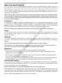
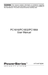
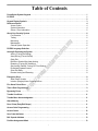
Table of Contents
1
1
2
3
4
4
4
5
About Your Security System . . . . . . . . . . . . . . . . . . . . . . . . . . . . . . . . . . . . . . . . . . . . . . . . . . . . . . . . . . . . .
Fire Detection. . . . . . . . . . . . . . . . . . . . . . . . . . . . . . . . . . . . . . . . . . . . . . . . . . . . . . . . . . . . . . . . . . . . . . .
Testing . . . . . . . . . . . . . . . . . . . . . . . . . . . . . . . . . . . . . . . . . . . . . . . . . . . . . . . . . . . . . . . . . . . . . . . . . . . .
Monitoring . . . . . . . . . . . . . . . . . . . . . . . . . . . . . . . . . . . . . . . . . . . . . . . . . . . . . . . . . . . . . . . . . . . . . . .
Maintenance. . . . . . . . . . . . . . . . . . . . . . . . . . . . . . . . . . . . . . . . . . . . . . . . . . . . . . . . . . . . . . . . . . . .
General System Operation. . . . . . . . . . . . . . . . . . . . . . . . . . . . . . . . . . . . . . . . . . . . . . . . . . . . . . . . . . .
6
6
6
6
6
6
.m
y
PowerSeries System Keypads . . . . . . . . . . . . . . . . . . . . . . . . . . . . . . . . . . . . . . . . . . . . . . . . . . . . . . . . . . . .
PC5532Z
......................................................................................
Keypad Display Symbols . . . . . . . . . . . . . . . . . . . . . . . . . . . . . . . . . . . . . . . . . . . . . . . . . . . . . . . . . . . . . . . .
Reference Sheets
Access Codes . . . . . . . . . . . . . . . . . . . . . . . . . . . . . . . . . . . . . . . . . . . . . . . . . . . . . . . . . . . . . . . . . . . . . .
System Information . . . . . . . . . . . . . . . . . . . . . . . . . . . . . . . . . . . . . . . . . . . . . . . . . . . . . . . . . . . . . . . . . .
Sensor / Zone Information . . . . . . . . . . . . . . . . . . . . . . . . . . . . . . . . . . . . . . . . . . . . . . . . . . . . . . . . . . . . .
m
PK5500 Language Selection . . . . . . . . . . . . . . . . . . . . . . . . . . . . . . . . . . .
..................... 7
ww
w.
ea
la
rm
.co
Arming & Disarming the System . . . . . . . . . . . . . . . . . . . . . . . . . . . . .
........................
Arming (Turning On/Setting) . . . . . . . . . . . . . . . . . . . . . . . . . . . . . . . . . . . . . . . . . . . . . . . . . . . . . . . .
Away Arming (Turned On/Set) . . . . . . . . . . . . . . . . . . . . . . . .
.............................
Quick Exit . . . . . . . . . . . . . . . . . . . . . . . . . . . . . . . . . . . . . . . . . . . . . . . . . . . . . . . . . . . . . . . . . . . . . . .
Bell/Siren Sounds After Away Arming . . . . . . . . . . . . . . . . . . . . . . . . . . . . . . . . . . . . . . . . . . . . . . . .
Disarming (Turning Off /Unsetting) . . . . . . . . . . . .
.....................................
Stay Arming (Partially Turning On / Part Setting) . . . . . . . . . . . . . . . . . . . . . . . . . . . . . . . . . . . . . . . . .
Re-activate bypassed zones . . . . . . . . . . . . . . . . . . . . . . . . . . . . . . . . . . . . . . . . . . . . . . . . . . . . . . . .
Silent Exit Delay . . . . . . . . . . . . . . . . . . . . . .
...........................................
Remote Arming and Disarming . . . . . .
..............................................
7
7
7
7
7
8
8
8
8
8
://
Emergency Keys . . . . . . . . . . . . . . . . .
................................................. 8
When Alarm Sounds . . . . . . . . . . . . . . . . . . . . . . . . . . . . . . . . . . . . . . . . . . . . . . . . . . . . . . . . . . . . . . . 9
Intrusion (Burglar) Alarm Continuous Siren . . . . . . . . . . . . . . . . . . . . . . . . . . . . . . . . . . . . . . . . . . . . . . . . 9
.
......................................................... 9
tp
Fire Alarm Pulsed Siren . . .
ht
Time & Date Programm ng . . . . . . . . . . . . . . . . . . . . . . . . . . . . . . . . . . . . . . . . . . . . . . . . . . . . . . . . . . . . . 9
Bypassing Zones . . . . . . . . . . . . . . . . . . . . . . . . . . . . . . . . . . . . . . . . . . . . . . . . . . . . . . . . . . . . . . . . . . . . . . 9
Trouble Conditions . . . . . . . . . . . . . . . . . . . . . . . . . . . . . . . . . . . . . . . . . . . . . . . . . . . . . . . . . . . . . . . . . . . . 11
Trouble Menu Acknowledgement . . . . . . . . . . . . . . . . . . . . . . . . . . . . . . . . . . . . . . . . . . . . . . . . . . . . . . . . 11
Alarm Memory . . . . . . . . . . . . . . . . . . . . . . . . . . . . . . . . . . . . . . . . . . . . . . . . . . . . . . . . . . . . . . . . . . . . . . . . 11
Door Chime (Entry/Exit Beeps) . . . . . . . . . . . . . . . . . . . . . . . . . . . . . . . . . . . . . . . . . . . . . . . . . . . . . . . . . . 11
Access Code Programming . . . . . . . . . . . . . . . . . . . . . . . . . . . . . . . . . . . . . . . . . . . . . . . . . . . . . . . . . . . . . 11
Access Codes . . . . . . . . . . . . . . . . . . . . . . . . . . . . . . . . . . . . . . . . . . . . . . . . . . . . . . . . . . . . . . . . . . . . . . . . 12
User Code Attributes . . . . . . . . . . . . . . . . . . . . . . . . . . . . . . . . . . . . . . . . . . . . . . . . . . . . . . . . . . . . . . . . . . 12
Bell Squawk Attribute . . . . . . . . . . . . . . . . . . . . . . . . . . . . . . . . . . . . . . . . . . . . . . . . . . . . . . . . . . . . . . . . . . 13
Partition Assignment Mask . . . . . . . . . . . . . . . . . . . . . . . . . . . . . . . . . . . . . . . . . . . . . . . . . . . . . . . . . . . . . 13
i
Erasing an Access Code . . . . . . . . . . . . . . . . . . . . . . . . . . . . . . . . . . . . . . . . . . . . . . . . . . . . . . . . . . . . . . . 13
User Function Commands . . . . . . . . . . . . . . . . . . . . . . . . . . . . . . . . . . . . . . . . . . . . . . . . . . . . . . . . . . . . . . 13
Changing LCD Display Brightness/Contrast. . . . . . . . . . . . . . . . . . . . . . . . . . . . . . . . . . . . . . . . . . . . . . . 15
Changing the Buzzer Level . . . . . . . . . . . . . . . . . . . . . . . . . . . . . . . . . . . . . . . . . . . . . . . . . . . . . . . . . . . . . 15
Label Programming . . . . . . . . . . . . . . . . . . . . . . . . . . . . . . . . . . . . . . . . . . . . . . . . . . . . . . . . . . . . . . . . . . . 15
Viewing the Event Buffer from an LCD Keypad . . . . . . . . . . . . . . . . . . . . . . . . . . . . . . . . . . . . . . . . . . . . 16
PK5500 Global Status Screen . . . . . . . . . . . . . . . . . . . . . . . . . . . . . . . . . . . . . . . . . . . . . . . . . . . . . . . . . . . 16
Sensor Reset . . . . . . . . . . . . . . . . . . . . . . . . . . . . . . . . . . . . . . . . . . . . . . . . . . . . . . . . . . . . . . . . . . . . . . . . . 16
17
17
17
17
17
.m
y
Testing Your System . . . . . . . . . . . . . . . . . . . . . . . . . . . . . . . . . . . . . . . . . . . . . . . . . . . . . . . . . . . . . . . . . .
Testing Your Keypad Sounder and Siren . . . . . . . . . . . . . . . . . . . . . . . . . . . . . . . . . . . . . . . . . . . . . . . . .
Testing Your Entire System . . . . . . . . . . . . . . . . . . . . . . . . . . . . . . . . . . . . . . . . . . . . . . . . . . . . . . . . . . .
Walk Test Mode . . . . . . . . . . . . . . . . . . . . . . . . . . . . . . . . . . . . . . . . . . . . . . . . . . . . . . . . . . . . . . . . . . .
Allowing Computer Access To Your System . . . . . . . . . . . . . . . . . . . . . . . . . . .
..............
Guidelines for Locating Smoke Detectors . . . . . . . . . . . . . . . . . . . . . . . . . . . . .
m
Household Fire Safety Audit . . . . . . . . . . . . . . . . . . . . . . . . . . . . . . . . . . .
.
ht
tp
://
ww
w.
ea
la
rm
.co
Fire Escape Planning . . . . . . . . . . . . . . . . . . . . . . . . . . . . . . . . . . . . .
ii
. . . . . . . . . . . . . . . . . 18
. . . . . . . . . . . . . . . . . . . . 19
. . . . . . . . . . . . . . . . . . . . . . . 19
PowerSeries System Keypads
PC5532Z
Zone
Lights
Function
Lights
PC5508Z
Status
Lights
[
PC5516Z
.m
y
Function
Buttons
m
Emergency
Keys
ww
LCD5501Z
w.
ea
la
rm
.co
Your installer may have installed
o e of these LED keypads if you
have 16 or fewer zones on your system. These keypads operate in the
same way as the PC5532 keypad.
Number
Pad
://
Liquid
Crystal
Display (LCD)
tp
Arrow
(Scroll)
Keys
ht
Status
Lights
LCD5500Z
Emergency
Keys
Function
Buttons
1
PK5500/PK5501
PC1555RKZ
Status
Lights
[
PK5508/PK5516 (shown)
Number
Pad
Zone
Lights
2
3
5
6
7
8
9
Reset
0
#
Bypass
.m
y
1
4
Emergency
Keys
Display
System
Lights
ht
tp
://
ww
LED5511
w.
ea
la
rm
.co
m
*
Number
Pad
2
LCD5511
Stay
Away
Chime
Keypad Display Symbols
LCD5501 Fixed Message
LCD5501 ICON
PK5501
5
9
6
14
7
11
17
9
7
10
11
8
LCD5511
10
PK5508/PK5516
LED5511
.m
y
20
Clock Digits 1, 2 – These two 7 segment clock digits indicate the hour digits when the lo al clock is active, and identify
the zone when the OPEN or ALARM icons are active. These two digits scroll one zone per second from the lowest zone
number to the highest when scrolling through zones.
2
: (Colon) – This icon is the hours/minutes divider and will flash once a second when the local clock is active.
.co
m
1
Clock Digits 3, 4 – These two 7 segment displays are the minute digits when the local clock is active.
4
1 to 8 – These numbers identify troubles when [,][2] is pressed.
rm
3
Memory – Indicates that there are alarms in memory.
6
Bypass – Indicates that there are zones automatically or manua y bypassed.
w.
ea
la
5
7
Program – indicates that the system is in Installer’s Programming, or the keypad is busy.
8
Away – Indicates that the panel is armed in the Aw y Mode. It will turn on at the beginning of the Exit Delay.
Fire – Indicates that there are fire alarms in memo y.
Stay – Indicates that the panel is armed in t e Stay Mode. It will turn on at the beginning of the Exit Delay.
11
Chime – This icon turns on when the Chime unction key is pressed to enable Door Chime on the system. It will turn off
when the chime function key is pressed again to disable Door Chime.
12
AM, PM – This icon indicates tha th local clock is displaying 12 Hr. time. These icons will not be on if the system is programmed for 24 Hr. time.
13
ALARM – This icon is used w th clock digits 1 and 2 to indicate zones in alarm on the system. When a zone is in alarm,
the ALARM icon will turn on, and 7 segment displays 1 and 2 will scroll through the zones in alarm.
14
OPEN – This icon is used with clock digits 1 and 2 to indicate violated zones (not alarm) on the system. When zones are
opened, the OPEN icon will turn on, and 7 segment displays 1 and 2 will scroll through the violated zones.
15
AC – Indicates that AC is present at the main panel.
ht
tp
://
ww
9
10
16
System Trouble – Indicates that a system trouble is active.
17
Night – Indicates that the panel is armed in the Night Mode.
18
System - Indicates one or more of the following:
Memory – Indicates that there are alarms in memory.
Bypass – Indicates that there are zones automatically or manually bypassed.
System Trouble – This icon is displayed when a system trouble is active.
19
Ready Light (green) – If the Ready light is on, the system is ready for arming.
20
Armed Light (red) – If the Armed light is on, the system has been armed successfully.
3
Reference Sheets
Fill out the following information for future reference and store this guide in a safe place.
Access Codes
Master Code [40] : _________________________
Code
Access Code
Code
Access Code
Code
Access Code
Code
10
19
28
02
11
20
29
03
12
21
30
04
13
22
31
05
14
23
3
06
15
24
07
16
25
08
17
26
09
18
27
34 (Duress)
rm
.co
m
.m
3 (Duress)
J [P] PANIC
w.
ea
J [A] AUXILIARY
la
System Information
Enabled?
J [F] FIRE
y
01
Access Code
ww
The Exit Delay Time is _______ seconds.
For Service
ht
tp
://
The Entry Delay Time is _______ seconds.
Central Station Information:
Account#: ___________________ Telephone#: __________________
Installer Information :
Company: ___________________ Telephone#: __________________
If you suspect a false alarm signal has been sent to the central monitoring station, call the station to
avoid an unnecessary response.
4
Sensor / Zone Information
Sensor
33
02
34
03
35
04
36
05
37
06
38
07
39
08
40
09
41
10
42
11
43
12
44
.co
01
13
45
46
rm
14
7
la
15
48
w.
ea
16
17
18
ww
19
24
51
54
tp
23
50
53
55
ht
22
49
52
://
20
21
Protected Area
y
Sensor Type
.m
Protected Area
m
Sensor
56
25
57
26
58
27
59
28
60
29
61
30
62
31
63
32
64
5
Sensor Type
About Your Security System
Your DSC Security System has been designed to provide you with the greatest possible flexibility and convenience. Read this manual carefully and have your installer instruct you on your system's operation and on which
features have been implemented in your system. All users of this system should be equally instructed in its use. Fill
out the “System Information” page with all of your zone information and access codes and store this manual in a
safe place for future reference.
NOTE: The PowerSeries security system includes specific false alarm reduction features and is classified with ANSI
/ SIA CP-01-2000. To comply with this specification, your installation must have a minimum of two keypads. Please
consult your installer for further information regarding the false alarm reduction features built into your system as all
are not covered in this manual.
Fire Detection
.m
y
This equipment is capable of monitoring fire detection devices such as smoke detectors and providing a warning
if a fire condition is detected. Good fire detection depends on having adequate number of detectors placed in
appropriate locations. This equipment should be installed in accordance with NFPA 72 (N.F.P.A., Batterymarch
Park, Quincey MA 02269). Carefully review the Family Escape Planning guidelines i th manual.
NOTE: Your installer must enable the fire detection portion of this equipment before i becomes functional.
m
Testing
rm
.co
To insure that your system continues to function as intended, you mus t s your system weekly. Please refer to
the “Testing your System” section in this manual. If your system do s not function properly, call your installing
company for service.
Monitoring
w.
ea
la
This system is capable of transmitting alarms, troubles and me gency information over telephone lines to a central station. If you inadvertently initiate an alarm, immedi tely call the central station to prevent an unnecessary
response.
NOTE: The monitoring function must be enabled by the installer before it becomes functional.
ww
SIA NOTE: There is a communicator delay of 30 seconds in this control panel. It can be removed, or it can be increased up to 45 seconds, at the option of the end user by consulting with the installer.
Maintenance
://
With normal use, the system requires minimum maintenance. Note the following points:
ht
tp
• Do not wash the security equipment with a wet cloth. Light dusting with a slightly moistened cloth should
remove normal accumulations of dust.
• Use the system test descr ed in “Testing Your System” to check the battery condition. We recommend, however, that the standby ba eries be replaced every 3-5 years.
• For other system devices such as smoke detectors, passive infrared, ultrasonic or microwave motion detectors or
glassbreak detectors, consult the manufacturer’s literature for testing and maintenance instructions.
General System Operation
Your security system is made up of a DSC control panel, one or more keypads and various sensors and detectors.
The control panel will be mounted out of the way in a utility closet or in a basement. The metal cabinet contains
the system electronics, fuses and standby battery.
NOTE: Only the installer or service professional should have access to the control panel.
All the keypads have an audible indicator and command entry keys. The LED keypads have a group of zone and
system status lights. The LCD keypad has an alphanumeric liquid crystal display (LCD). The keypad is used to send
commands to the system and to display the current system status. The keypad(s) will be mounted in a convenient
location inside the protected premises close to the entry/exit door(s).
6
The security system has several zones of area protection and each of these zones will be connected to one or
more sensors (motion detectors, glassbreak detectors, door contacts, etc.). A sensor in alarm will be indicated by
the corresponding zone lights flashing on a LED keypad or by written messages on the LCD keypad.
Additional features of the PC1616/PC1832/PC1864 Security System are an Automatic Inhibit (Swinger Shutdown)
for Alarm, Tamper and Trouble signals after 3 occurrences in a given set period (see Section 5.6 Option [377] in
the Installation Manual). There is also a Programmable Keypad Lockout option (see Section 5.3 Option [012] in
the Installation Manual).
IMPORTANT NOTICE
A security system cannot prevent emergencies. It is only intended to alert you and – if included – your central station of an emergency situation. Security systems are generally very reliable but they may not work under all conditions and they are not a substitute for prudent security practices or life and property insurance. Your security
system should be installed and serviced by qualified security professionals who should instruct you on the level of
protection that has been provided and on system operations.
y
PK5500 Language Selection
3. Press
keys simultaneously.
keys, scroll through the available languages.
to select your desired language.
.co
2. Using the
m
1. Press and hold both
.m
Your keypad may have the capability to display messages in different languages
rm
Arming & Disarming the System
Arming (Turning On/Setting)
la
Close all sensors (i.e. stop motion and close doors). The Read ( ) indicator should be on.
ww
Away Arming (Turned On/Set)
w.
ea
To arm, press and hold the Away key for 2 seconds and/ r enter your Access Code, or press
to Quick
Arm. During the setting state (exit delay active) the A med ( ) and Ready ( ) indicators will turn on, and the keypad will sound one beep per second. You now have ____ seconds to leave the premises (please check with your
installer to have this time programmed). To cance e arming sequence, enter your access code.
Quick Exit
://
When the exit delay is completed, the al rm system is armed/set and this is indicated on the keypad as follows:
the Ready ( ) indicator will turn off the A med indicator will remain on and the keypad will stop sounding.
ht
tp
If the system is armed and you need to exit, use the Quick Exit function to avoid disarming and rearming the system. Press and hold the Exi key for 2 seconds or press
. You now have 2 minutes to leave the premises
through your exit door. Whe the door is closed again, the remaining exit time is cancelled.
Bell/Siren Sounds After Away Arming
Audible Exit Fault
In an attempt to reduce false alarms, the Audible Exit Fault is designed to notify you of an improper exit when
arming the system in the Away mode. In the event that you fail to exit the premises during the allotted exit delay
period, or if you do not securely close the Exit/Entry door, the system will notify you that it was improperly armed
in two ways: the keypad will emit one continuous beep and the bell or siren will sound.
Your installer will tell you if this feature has been enabled on your system. If this occurs:
1. Re-enter the premises.
2. Enter your [access code] to disarm the system. You must do this before the entry delay timer expires.
3. Follow the Away arming procedure again, making sure to close the entry/exit door properly. (See “Away Arming (Turned On/Set)”.)
7
Arming Error
An error tone will sound if the system is unable to arm. This will happen if the system is not ready to arm (i.e. sensors are open), or if an incorrect user code has been entered. If this happens, ensure all sensors are secure, press
and try again.
Disarming (Turning Off /Unsetting)
Enter your access code to disarm anytime the system is armed (i.e. Armed ( ) indicator is on). The keypad will
beep if you walk through the entry door. Enter your code within _____ seconds to avoid an alarm condition
(please check with your installer to have this time programmed).
Disarming Error
If your code is invalid, the system will not disarm and a 2-second error tone will sound. If this happens, press
and try again.
Stay Arming (Partially Turning On / Part Setting)
la
rm
.co
m
.m
y
Stay arming will bypass the interior protection (i.e. motion sensors) and arm the perimeter of the system (i.e.
doors and windows). Close all sensors (i.e. stop motion and close doors). The Ready ( ) indicator should be on.
Ask your alarm company if this function is available on your system.
Press and hold the Stay key for 2 seconds and/or enter your Access Code and do not leave the premises (if your
installer has programmed this button). During the setting state (exit delay ac ve), the Armed ( ) and Ready ( )
indicators will turn on, and the keypad will sound one beep every three sec nds.
When the exit delay is completed, the alarm system is armed/set and thi i indicated on the keypad as follows:
the Ready ( ) indicator will turn off, the Armed ( ) indicator will remain on and the keypad will stop sounding.
The Armed ( ) indicator and Bypass or System indicator will tur on The system will automatically bypass certain
interior sensors (i.e. motion sensors).
NOTE: For SIA FAR listed panels, the Stay Arming Exit D lay will be twice as long as the Away Arming Exit Delay.
w.
ea
Re-activate bypassed zones
To fully arm the system when it has been armed in S y mode:
Press
at any keypad. The interior zones ar
ow armed.
ww
NOTE: When the interior zones have been re-ac vated, you will not be able to enter areas protected by motion detectors, or open doors and windows. To acces these areas, enter your [access code] and disarm the system.
://
Silent Exit Delay
ht
tp
If the system is armed using the STAY button (Programmable Function Key) or using the "No Entry" Arming
method (
[access code]) he audible progress annunciation (keypad buzzer) will be silenced and the exit
time will be doubled for tha ex p riod only.
Remote Arming and D sarming
The system can be armed and/or disarmed using the remote control device (wireless key) model DSC WS4939.
When arming the system by using the Arm button on the wireless key, the system will acknowledge the command
by sounding a single bell squawk and when disarming using the Disarm button on the wireless key the system will
acknowledge the command by sounding two bell squawks that can be heard from the exterior of the premises.
Emergency Keys
Press the (F), (A) or (P) key for 2 seconds to generate a Fire, Auxiliary or Panic alarm. The keypad sounder
will beep indicating that the alarm input has been accepted and transmission to the central station is underway.
Ask your alarm company if the emergency keys are available on your system.
NOTE: The Fire keys can be disabled by the installer.
LED5511/LCD5511 Keypad
Press and hold both keys simultaneously for 2 seconds to send the following messages:
Fire Message,
Auxiliary Message,
Panic Message.
8
When Alarm Sounds
The system can generate 2 different alarm sounds:
Continuous Siren = Intrusion (Burglary Alarm)
Temporal / Pulsed Siren = Fire Alarm
Intrusion (Burglar) Alarm Continuous Siren
If you are unsure of the source of the alarm approach with caution ! If the alarm was accidental,
enter your Access Code to silence the alarm. Call your central station to avoid a dispatch.
Fire Alarm Pulsed Siren
Follow your emergency evacuation plan immediately!
If the fire alarm was accidental (i.e. burned toast, bathroom steam, etc.), enter your Access Code to silence the
alarm. Call your central station to avoid a dispatch. Ask your alarm company if your system has been equipped
with fire detection.
.m
y
To reset the detectors, see the Sensor Reset section.
Time & Date Programming
m
.co
Press
, plus your Master Access Code or press the time programming f nction key (programmed by your
to select Time and Date.
When using the LCD5500, use the
scroll keys to find the menu option and press
rm
Press
installer).
Enter the time in 24-hr format (HH:MM), followed by the date MM:DD:YY). Press
to select.
to exit programming.
w.
ea
la
NOTE: If you have an LCD keypad, your installer may hav pro rammed your system to display the time and date
while the keypad is idle. If this is the case, you can press h
key to clear the date and time display.
Bypassing Zones
://
ww
Use the zone bypassing feature when you need ac ess to a protected area while the system is armed, or when a
zone is temporarily out of service, but you need to arm the system. Bypassed zones will not be able to sound an
alarm. Bypassing zones reduces the level of se urity. If you are bypassing a zone because it is not working, call a
service technician immediately so that th problem can be resolved and your system returned to proper working
order. Ensure that no zones are unin en ionally bypassed when arming your system.
tp
Zones cannot be bypassed once the system is armed. Bypassed zones are automatically cancelled each time the
system is disarmed and must be b passed again, if required, before the next arming.
ht
NOTE: For security reaso s, your installer has programmed the system to prevent you from bypassing certain zones
(e.g., smoke detectors).
Bypassing Zones with an LCD5500Z keypad
Start with disarming the system.
1. Press
to enter the function menu. The keypad will display “Press , for < > Zone Bypass”.
2. Press
or
, then your [access code] (if required). The keypad will display “Zone Search < > Zone Name”.
3. Enter the two-digit number of the zone(s) to be bypassed (01-64).
You can also use the
keys to find the zone to be bypassed, and then press
to select the zone.
The keypad will display “Zone Search < > “Zone Name?”. “B” will appear on the display to show that the zone is
bypassed. If a zone is open (e.g., door with door contact is open), the keypad will display “Zone Search < >
“Zone Name” O”. If you bypass the open zone, a “B” will replace the “O”.
9
4. To unbypass a zone, enter the two-digit number of the zone(s) to be bypassed (01-64). You can also use the
keys to find the zone, and then press
to select the zone. The “B” will disappear from the display to show that the zone is no longer bypassed.
5. To exit bypassing mode and return to the Ready state, press
.
Bypassing Zones with a PC55XXZ or LCD5501Z keypad
Start with disarming the system
.
1. Press
.m
, then your [access code] (if necessary).
.
.co
2. Press
y
4. To exit bypassing mode and return to the Ready state, press
Activating All Bypassed Zones
To activate all bypassed zones:
m
1. Press
, then your [access code] (if required).
2. Enter the two-digit number of the zone(s) to be bypassed (01-64). On PC55XXZ keypads, the zone light will
turn on to indicate that the zone is bypassed.
3. To unbypass a zone, enter the two-digit number of the zone (01-64). On PC55XXZ keypads, the zone light
will turn off to indicate that the zone is not bypassed.
, then your [access code] (if necessary)
w.
ea
1. Press
2. Press
la
rm
3. To exit bypassing mode and return to the Ready state, press
Recalling Bypassed Zones
To recall the last set of bypassed zones:
.
tp
://
ww
3. To exit bypassing mode and return to the Ready tate, press
.
Bypass Groups
A Bypass Group is a selection of zones pr g ammed into the system. If you bypass a group of zones on a regular
basis, you can program them into the Bypass Group, so that you do not have to bypass each zone individually
every time. One Bypass Group can be programmed on each partition.
To program a Bypass Group:
ht
1. Press
, then your [access code] (if necessary).
2. Enter the two-digit numbers (01-64) of the zones to be included in the Bypass Group. On LCD5500Z keypads,
you can also use the
select the zone.
keys to find the zone to be included in the bypass group, and then press
3. To save the selected zone into the group, press
.
4. To exit bypassing mode and return to the Ready state, press
.
To select a Bypass Group when arming the system:
1. Press
, then your [access code] (if necessary).
2. Press
. The next time the system is armed, the zones in this group will be bypassed.
3. To exit bypassing mode and return to the Ready state, press
.
NOTE: Bypass Groups are only recalled if the system is armed/disarmed after programming the bypass group.
NOTE: This feature is not to be used in UL Listed installations.
10
to
Trouble Conditions
When a trouble condition is detected, the Trouble ( ) or System indicator will turn on, and the keypad will beep
every 10 seconds. Press the
key to silence the beeps. Press
to view the trouble condition. The Trouble
( ) or System indicator will flash. The corresponding trouble will be represented by numbers 1-8.
6
7
8
Call for service
If the building and/or neighbourhood has lost electrical power,
the system will continue to operate on battery for several hours.
Call for service
Telephone Line Fault
The system has detected that the telephone line is cut.
Call for service
Failure to Communicate
The system attempted to communicate with the monitoring station, but failed. This may be due to Trouble 3.
Call for service
Sensor (or Zone) Fault
The system is experiencing difficulties with one or more sensors
on the system.
Call for service
Sensor (or Zone) Tamper
The system has detected a tamper condition with one or more
sensors on the system.
Call for service
Sensor (or Zone) Low Battery
If the system has been equipped with wireless ensors, one or
more has reported a low battery condi i n
Call for service
Loss of Time & Date
If complete power was lost (AC and Battery), the time and date
will need to be re-programmed
Loss of AC Power
y
5
Service Required
.m
3
4
Action
m
2
Comments
.co
1
Trouble Condition
Re-program Time
& Date (page 9)
rm
LED/
DIGIT
Trouble Menu Acknowledgement
w.
ea
la
If the Arming Inhibit for All Troubles features is enabled, Trouble Menu Acknowledgement may be used. To use
this feature while in the Trouble Menu (
), press
t acknowledge and override the existing troubles, so
the system can be armed. An override event will also be generated and logged, thus identifying the user. To override open zones, use the Zone Bypass feature (
).
ww
Alarm Memory
When an alarm occurs, the Memory or Sys em indicator (and Fire indicator, if applicable) will turn on.
. The Memory or System indicator and corresponding
://
To view which sensor(s) generated the al m, press
sensor number will flash (i.e. sensor 3).
scroll keys to view the sensors in alarm memory.
to exit. To clear the memory, arm and disarm the system.
ht
Press
tp
For the LCD5500 keypad use the
If an alarm sounded while armed, the keypad will automatically go to alarm memory when you disarm the system. In this instance, you should approach with caution, as the intruder may still be within the building/premises.
Door Chime (Entry/Exit Beeps)
To turn the door chime function on or off, press and hold the Chime key for 2 seconds or press
.
Access Code Programming
In addition to the Master Access Code, you can program up to 32 additional User Access codes. Press
, plus
your Master Access Code. The Program or System indicator will begin to flash, and the Armed ( ) indicator will
turn on.
Enter the 2-digit number to be programmed (i.e. 06 for user access code 6; enter 40 for the Master Access Code).
When using the LCD5500, use the
keys to find the specific code and press
to select. Enter the new 4digit access code, or press
to erase it. When programming is complete, enter another 2-digit code to program
or press
to exit.
11
For systems using multiple partitions/areas, access codes can be assigned to specific or multiple partitions/areas.
Please contact your alarm company for details.
The minimum number of variations of access codes (key) is 27027 when 37, 6-digit user codes are used. For SIA
Installations, duplicate or duress codes derived from user codes +/- 1 digit are not allowed.
The access codes have programmable attributes which allow zone bypassing, remote access using the
ESCORT5580TC or one-time use activation.
Access Codes
[,][5][Master Code] (when disarmed)
The [,][5] User’s Programming command is used to program additional access codes.
User Codes (Access Codes 1-32)
Master Code (Access Code 40) - The Master Code can only be changed by the Installer, if programmed.
.m
y
Supervisor Codes (Access Codes 41 & 42) - These codes are always valid when entering the
User Code
Programming section. However, these codes can only program additional codes which have equal or lesser
attributes. Once programmed, the Supervisor Codes receive the Master Code’s a rib tes. These attributes are
changeable.
.co
m
Duress Codes (Access Codes 33 & 34) - Duress codes 33 and 34 are standa d User Codes that will transmit the
Duress Reporting Code whenever the code is entered to perform any func on on the system.
NOTE: Duress codes are not valid when entering [,][5], [,][6] or [,][8] sections.
rm
NOTE: No codes can be programmed as a duplicate of another code
la
NOTE: Duress codes cannot be programmed as a duplicate or as a Code + 1”.
User Code Attributes
w.
ea
1. The default attributes of a new code will be the at ibutes of the code used to enter
whether it is a new
code or an existing code being programmed.
2. System Master (Code 40) has Partition Access r all partitions, as well as Attributes 3-4 ON by default.
ww
NOTE: These attributes are not changeable
://
Inherent Attributes (all codes ex ep installer and maintenance)
Arm / Disarm - Any Access Code with Partition Access enabled will be valid for arming and disarming that partition.
Command Outputs ([,][7][1], [,][7][2], [,][7][3], and [,][7][4]) - If these outputs require Access Code entry, any
ht
tp
Access Code with Partition Acc ss will be valid for performing the [,][7][1-4][Access Code] functions on that partition.
Programmable Attributes ([,][5][Master/Supervisor Code][9][Code])
1.
2.
3.
4.
5.
6.
7.
8.
For Future Use
For Future Use
Zone Bypassing Enabled
ESCORT Access
Downlook Remote Trigger to Phone Number 1
Downlook Remote Trigger to Phone Number 2
Bell Squawk upon Arming/Disarming
One Time Use Code
NOTE: Attributes 5 and 6 cannot be enabled on the same access code.
12
Bell Squawk Attribute
This attribute is used to determine whether an access code should generate an arming/disarming Bell Squawk
upon entry of the code for Away arming. The Wireless Keys with access codes associated with them may generate Arming/Disarming Bell squawks. If desired, this option may be used with codes that are manually entered.
Please contact your installer to have this programmed.
NOTE: The Master Code cannot use the Bell Squawk attribute, but is required to enable it for other codes.
NOTE: This feature cannot prevent the Arm/Disarming squawks from being generated if an access code assigned to
a WLS Key is manually entered at a keypad.
Partition Assignment Mask
In order to accommodate Access Code Partition Assignment for the multiple partitions found on this product the
user must enter [,][5][Master Code][8][Code number to be change] (ex. [,][5][1234][8][Code 03]. Under this section, each bit represents the corresponding partition’s access (i.e. Bit 4 represents Partition 4 access).
.m
w.
ea
Notes on Access Codes and Programming
la
rm
.co
m
Partition Assignment Mask ([,][5][Master/Supervisor Code][8][Code])
1. Partition One Access
2. Partition Two Access
3. Partition Three Access
4. Partition Four Access
5. Partition Five Access
6. Partition Six Access
7. Partition Seven Access
8. Partition Eight Access
y
The Master Code has access to all partitions, and cannot be modified.
ht
tp
://
ww
1. There will still be 37 codes if option selected for 6 digit access codes.
- [,][5][MASTER CODE] [01 to 32, 33, 34, 40 41, 42] to program access codes
- [,][5][MASTER CODE][8] enters the Partition Assignment Mode [01 to 32, 33, 34, 41, 42] to edit access code
partition assignments
- [,][5][MASTER CODE][9] Enters the A tr bute Mode [01 to 32, 33, 34, 41, 42] to edit access code Attributes.
2. The Master Code’s attributes canno be changed.
3. When a new code is programmed in
it will be checked against all other codes in the system. If a duplicate code is found, an erro tone is given and the code is returned to what it was before it was changed. This
applies to both 4 and 6 digit codes.
Erasing an Access Code
To erase a code, select the code and enter
as the first digit. If
immediately and the user will be returned to select another code.
is entered, the system will delete the code
User Function Commands
First disarm the system then enter
The
[Master Code]
command is used to gain access to the following list of Master functions of the system.
[1] Time and Date
Enter 4 digits for 24 Hour System Time (HH-MM). Valid entries are 00-23 for the hour and 00-59 for minutes.
Enter 6 digits for the Month, Day and Year (MM-DD-YY)
13
[2] Auto-arm Control
Pressing [2] while in the User Function menu will enable (3 beeps) or disable (one long beep) the Auto-arm feature, by partition. With this feature enabled, the panel will automatically arm in the Away mode (Stay Away zones
active) at the same time each day. The auto-arm time is programmed with the [,][6][Master Code][3] command.
[3] Auto-arm Time
The system can be programmed to arm at a programmed time each day, per partition.
Upon entry of this section, enter 4 digits for the 24-hour Auto-arm time for each day of the week.
At the selected auto-arm time, the keypad buzzers will sound for a programmed amount of time (programmable
by the installer only) to warn that an auto-arm is in progress. The bell can also be programmed to squawk once
every 10 seconds during this warning period. When the warning period is complete, the system will arm with no
exit delay and in the Away Mode.
y
Auto-arming can be cancelled or postponed by entering a valid access code only, during the programmed warning period. Auto-arming will be attempted at the same time the next day. When the auto-arming process is cancelled or postponed, the Auto-arm Cancellation Reporting Code will be transmitted (if programmed).
.m
If arming is inhibited by one of the following, the Auto-arm Cancellation transm ss on will be communicated.
m
- AC / DC Inhibit Arm
.co
- Latching System Tampers
- Zone Expander Supervisory Fault
la
rm
[4] System Test
The system’s Bell Output (2s), Keypad Lights and Communicat r are tested. This test will also measure the panel’s
standby battery.
://
ww
w.
ea
[5] Enable DLS / Allow System Service
If enabled, the installer will be able to access Installer Programming by DLS. In case of DLS access this provides a
window where rings will be detected by the panel The DLS window will remain open for 6hrs, during which time
the installer will be able to enter DLS an unlimited number of times. After the 6-hr window has expired, Installer’s
Programming will be unavailable again until the window is re-opened.
[6] User Call-up
If enabled by the Installer, the pane will make 1 attempt to call the downloading computer. The downloading
computer must be waiting for the panel to call before downloading can be performed.
ht
tp
[7] Music Input On/Off
If enabled on the PC5936 Audio Interface Module, the user can turn Background Music on or off.
[8] User Walk Test (For Europe only)
This test allows the user to verify operation of system detectors and notifies the central station that a Walk Test is
in progress.
Note: Fire zones, the 'F' key, and 2-wire Smoke detectors are excluded from this test. Violation of these zones will
cause the system to exit the walk test then generate and transmit alarm condition to the central station.
1. Press
to enable Walk Test. The system will notify the Central Station that a walk test has begun.
6
2. Violate all each detector (zone) in sequence. A squawk will occur at the keypad and the violation will be
recorded in the Event Buffer.
3. Restore zones. Press
6
test has been terminated.
to end the Walk Test. The system will notify the Central Station that the walk
Note: If a zone is not violated within 15 minutes of activating the Walk Test, the system will automatically exit the
Walk Test and resume normal operation.
14
Changing Brightness/Contrast
When this option is selected, the keypad will allow you to scroll through 10 different brightness/contrast levels.
1. Press
[Master code].
2. Use the
keys to scroll to either Brightness Control or Contrast Control.
3. Press
to select the setting you want to adjust.
4. a) ‘Brightness Control’: There are multiple backlighting levels. Use the
keys to scroll to the desired level.
b) ‘Contrast Control’: There are 10 different display contrast levels. Use the
keys to scroll to the
desired contrast level.
5. To exit, press
.
[Master Code].
2. Use the
key to move through the 4 different backlighting levels.
to exit.
.co
Changing the Buzzer Level
m
3. The level is automatically saved when you press
.m
1. Press
y
PK5501/PK5508/PK5516 keypads
When this option is selected, the keypad will allow you to scroll through 4 different backlighting levels. A level of
0 disables the backlighting.
la
[Master Code].
2. Use the
keys to scroll to Buzzer Control.
3. There are 21 different levels, use the
PK5501, PK5508, PK5516 keypads:
w.
ea
1. Press
rm
When this option is selected, the keypad will allow you to scroll through 21 different buzzer levels. A level of 00
disables the buzzer.
keys to scroll to the desired level.
[Master Code].
2. Use the
key to move through the 2 different buzzer levels.
ww
1. Press
://
3. The level is automatically saved when you press
to exit.
ht
PK5500/LCD keypad
tp
Label Programming
When this option is select d, the keypad will allow you to program labels representing zones, partitions, and
command outputs. Also, special labels can be added to show when the system fails to arm or when you disarm
after an alarm has occurred.
1. Press
[Master Code].
2. Use the
keys to scroll to Edit Labels.
3. Use the
keys to select the label type you want to edit.
4. Use the
keys to select the individual label you want to edit.
5. Use the arrow keys (
) to move the underline bar underneath the letter to be changed.
6. Press the number keys [1] to [9] corresponding to the letter you require. The first time you press the number
the first letter will appear. Pressing the number key again will display the next letter.
15
Refer to the following chart:
[1] - A, B, C, 1
[2] - D, E, F, 2
[3] - G, H, I, 3
[4] - J, K, L, 4
[5] - M, N, O, 5
[6] - P, Q, R, 6
[7] - S, T, U, 7
[8] - V, W, X, 8
[9] - Y, Z, 9,0
[0] - Space
7. When the required letter or number is displayed use the arrow keys (
8. When you are finished programming the Zone Label, press the
9. Continue from Step 2 until all Labels are programmed.
) to scroll to the next letter.
key, scroll to “Save,” then press
.
Viewing the Event Buffer from an LCD Keypad
rm
.co
m
.m
y
The event buffer will show you a list of the last 500 events that have occurred on your system. You must use an
LCD keypad to view the event buffer.
1. Press
[Master Code].
2. To select Event Buffer viewing, press
.
3. The keypad will display the event number, partition or area, and the time and date. Press
to switch
between this information and the event details.
4. Use the
keys to scroll through the events in the buffer.
5. To exit event buffer viewing, press
.
PK5500 Global Status Screen
w.
ea
la
When the keypad is loaned to global mode (pressing and holding the
key), you will see a Global Partition Status screen. This shows basic status for up to 8 partitions d pending on the configuration of your system. The
screen looks similar to the example shown below.
1
3 4 5 6 7 8
ww
A R ! N - - - -
Each partition is identified by a number. B
w each number is the current status of that partition.
://
A - Partition is Armed
tp
N - Partition is Not Ready to Arm
ht
R - Partition is Ready to Arm
! - Partition is in Alarm
- - Partition is Not Enabled
Sensor Reset
Certain sensors, after having detected an alarm condition, require a Reset to exit the alarm condition (i.e. glass
break sensors, smoke detectors, etc.). Ask your alarm company if this function is required on your system.
To reset the detectors, press and hold the Reset key for 2 seconds or press
.
If a sensor fails to reset, it may still be detecting an alarm condition. If the sensor reset is successful, the alarm is
cancelled. If unsuccessful, the alarm will reactivate or continue.
16
Testing Your System
NOTE: If you are going to perform a System Test, call your Monitoring Station to inform them when you begin and
also when you end the test.
Testing Your Keypad Sounder and Siren
The System Test provides several system tests, and a two-second check of the keypad sounder and bell or siren.
1. Press
[Master Code]
.
2. The following will occur:
- The system activates all keypad sounders and bells or sirens for two seconds. All keypad lights turn ON.
- LCD5500Z keypads will light all pixels
- The Ready, Armed, and Trouble LED’s will flash for the duration of the test
3. To exit the function menu, press
.
Testing Your Entire System
.m
y
All smoke detectors in this installation must be tested by your smoke detector instal er or dealer once a year to
ensure they are functioning correctly. It is the user’s responsibility to test the sys em weekly (excluding smoke
detectors). Ensure you follow all the steps in the ‘Testing Your System’ section above.
rm
.co
Prior to testing, ensure that the system is disarmed and the Ready ligh is on.
Press
and close all zones to return the system to the Ready sta e.
Perform a System Test by following the steps in the previous ecti n.
To test the zones, activate each detector in turn (e.g., open each door/window or walk in motion detector
areas).
PK55xx/LCD5500Z keypads will display the follow ng message when each zone (detector) is activated:
“Secure System Before Arming < >”, “Secure System or Enter Code” or “Secure or Arm System”. Use the
keys to view which zones are open The message will disappear when the zones are closed.
On an LCD5501Z keypad, the display says
pen” when any zone (detector) is activated. To see which
zones are open, press
. The keypad w l scroll the numbers of all open zones.
On a PC55XXZ keypad, the zone ligh urns ON when the zone (detector) is activated. The zone light turns
OFF when the zone is closed (e.g door or window closed).
://
ww
w.
ea
la
1.
2.
3.
4.
m
NOTE: Should the system fail to function properly, call your installation company for service immediately.
ht
Walk Test Mode
tp
NOTE: Some features described above will not be functional unless enabled by your installer. Ask your installer which
features are functional on your ys em.
The installer can initiate a Walk Test mode for the system. While in Walk Test mode, The Ready, Armed, and Trouble LED's will flash to indicate that Walk Test is active. When the system automatically terminates the Walk Test
modes, it will annunciate with an audible warning (5 beeps every 10 seconds), beginning five minutes prior to the
termination of the test.
Allowing Computer Access To Your System
From time to time, your installer may need to send information to or retrieve information from your security system. Your installer will do this by having a computer call your system over the telephone line. You may need to
prepare your system to receive this ‘downloading’ call. To do this:
1. Press
[Master code]
at any keypad. This allows downloading for a limited period of time. During
this time, the system will answer incoming downloading calls.
For more information on this feature, please ask your installer.
17