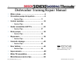
1
/ 1 / / Dishwasher Training/Repair Manual • Water valves…………………………………..… 4 • Circulation pumps & impellers……………….6 • Service Tips……………………………….. 11 • Control modules……………………………….14 • Service Tips……………………………….. 22 • Heater assemblies & NTC’s………………….23 • Service Tips……………………………….. 27 • Drain pumps…………………………………… 34 • Service Tips……………………………….. 35 • Dispensers…………………………………….. 36 • Service Tips……………………………….. 39 • Cosmetic damage…………………………….. 42 • Service Tips……………………………….. 43 • Door latches…………………………………… 44 • Service Tips……………………………….. 46 NOTE: Dishwashers are rated 120V, 60 Hz, 15A, 1450W (max.). Maximum amp draw when heaters running ~ 11A. • Aqua sensors……………………………...……48 • Water fill assemblies………………………….49 • Miscellaneous service tips…………………..50 702_58300000125963_ara_en_a 2nd Edition/Revision 6 (8/3/07) / / 2 / Warnings • m WARNING Modern appliances are very powerful and use high technology devices to safely control that power. Failure to use the correct procedures and the approved parts can create serious hazards for the person servicing the appliance and for the user of an appliance with a bad repair. If you do not know how to service the appliance, do not attempt to do so! • To avoid the risk of serious injury or death while servicing these appliances: • • Be certain that all power is removed from the appliance before beginning service. • Carefully follow all servicing instructions. Verify the instructions if there are any that you don't fully understand. • Read and heed all Cautions and Warnings on the appliance and those with the replacement parts. • Use caution and proper protective gear when handling chassis panels. Some of the edges that are not normally exposed may be very sharp. To avoid risk of serious injury or death to the users of the appliances: • Carefully follow all service instructions. • Use only parts authorized for the application. • Know the testing requirements needed to verify the safety of the service action. • Use proper, calibrated test equipment. • Do all indicated safety tests and record results. 702_58300000125963_ara_en_a 2nd Edition/Revision 6 (8/3/07) / 3 / / Warranty Serial # Info The serial label is fastened to the right edge of the inner door. Understanding FD Serial # (used for warranty) FD8303 00001 The FD # shows the Fabrication Date • The first 2 #s represent the year: 83 = 2003 • The next 2 #s represent the month: 03 = March • The next 5 #s represent the unit made that month: 00011 = 11th SHU3307UC made that month 10 3 03 0081344 00011 5 Please hold all warranty parts for (60) days for possible return for analysis. 702_58300000125963_ara_en_a • • • • • • This helps the factory investigate product problems. Understanding Factory Serial # The first 2 #’s represent a factory code: 10 = New Bern dishwasher, 82 = New Bern cooking The 3rd # represents the last digit of the year: 3 = 2003 The next 2 #’s represent the month: 03 = March The next 7 #’s represent the model: 0081344 = SHY99S05UC The next 5 #’s represent the unit made that month: 00011 = 11th SHY99A05UC made that month The last # represents a check digit = 5 in this case (is dependent on all preceding #’s) 2nd Edition/Revision 6 (8/3/07) / / 4 / Part # 1 -- Water Valve (1) Disassembly Access the water valve from the front of the dishwasher base by removing the toe kick. To remove water valve: Tools needed: T20 Torx screwdriver & pliers. 1. Remove two (2) T-20 Torx screws from toe kick and tilt toe kick out from under dishwasher. 2. 3. 4. 5. 6. Old style valve shown Remove base insulation (on models with insulation). Move sump inlet hose away from water valve (without disconnecting it). Disconnect wires from water valve, including ground wire. Remove two (2) T-20 Torx screws from water valve. Pull valve out from dishwasher and disconnect water hose from rear of valve. Remove any water from sump & base. Removing toe kick Moving sump hose CONNECTION HINTS: Water connection 3/8” NPT female. Inlet water pressure range 5 120 psi (0.3 – 8.27 bars). Removing hose clamp Old style valve shown Old style valve shown 702_58300000125963_ara_en_a 2nd Edition/Revision 6 (8/3/07) / 5 / / Part # 1 -- Water Valve (2) Service Tips New style 580009 (yellow stem) or 167081 (white stem) 425458 & 189533 Old style Don’t use 189533 to replace 425458 NOTE: Water valves have been upgraded several times since 1st 1/4 of 1999. • New time-fill valve # 425458 looks like pressure-fill valve # 189533, but isn’t the same. Don’t use # 189533 to replace it. • Use time-fill valve # 425458 to replace pressure-fill valve # 189533. • Current pressure-fill valve (part # 189533) has a horizontally mounted solenoid and water fitting held in place by the metal mounting bracket. Its the only replacement pressure-fill valve available and replaces all other valves. • Older pressure-fill valves (580009 & 167081) were both replaced by 189533. 702_58300000125963_ara_en_a HINTS: • When reconnecting the water supply to the water valve, don’t overtighten the elbow fitting. On valves with vertical solenoids, the plastic can crack and cause leaking if excessive force is used. • Using Teflon tape on water fittings can help prevent leaking. • The water valve can be accessed without removing outer door or base cover. However, removing them will provide easier access. 2nd Edition/Revision 6 (8/3/07) / 6 / / Part # 2 -- Circulation Pump & Impeller (1) Access The circulation pump & capacitor are accessed from the right side of the dishwasher by removing the right side panel and blocking the tank. Use same process to access heater & Apexx modules. To remove outer door: Tools needed: T20 Torx screwdriver. 1. Remove six T-20 Torx inner door screws below fascia panel -- three per side (1). 2. Carefully pull bottom of outer door out from dishwasher until top door tabs clear, then pull door down until it releases from dishwasher (2). Take care to not scratch outer door. 3. Remove 1-piece foam or two plastic door guards (3). The plastic door guards occasionally fall out when the outer door is removed. 1 2 NOTE: Circulation pump 239144 motor is rated 120V, 60 Hz, 160W, insulation class A. Motor has an autoreset thermal protector and uses a 10μF capacitor. 702_58300000125963_ara_en_a 3 HINT: The fascia panel and door don’t need to be removed to access the circulation pump. However, they must be removed to completely remove the tank. 2nd Edition/Revision 6 (8/3/07) / / 7 / Part # 2 -- Circulation Pump & Impeller (2) To remove toe kick: 1 2 Tools needed: T20 Torx screwdriver. 1. Remove two T-20 Torx screws from toe kick (1). 2. Tilt toe kick out from under dishwasher (2). To remove right & left side panels: Tools needed: T20 Torx screwdriver. Dishwashers may have long or short side panels, depending on model. Removing the left side panel isn’t necessary for access, but allows the right side of the tank to be blocked upward. 1. For models with long side panels, remove two T-20 Torx side panel screws through holes in right & left trim strips (1). 2. To remove long side panels, lift panels with trim strips up and out from dishwasher (2). 3. To remove short side panels, remove two T-20 Torx screws (3). To avoid damaging trim strips (while blocking tanks), slide trim strips up until they clear dishwasher bases. 1 Long side panels shown 2 Long side panels shown 702_58300000125963_ara_en_a 3 3 Short side panels shown Long side panels shown Short side panels shown 2nd Edition/Revision 6 (8/3/07) / / 8 / Part # 2 -- Circulation Pump & Impeller (3) To raise right side of tank for circulation pump access: Tools needed: T20 Torx screwdriver and pliers. 1. Remove one T-20 Torx screw from both rear corners holding tank to base (1) -- removing screw 2. 3. 4. 5. from both sides allows tank to be blocked upward. Remove right toe kick bracket by removing T-20 Torx screw (2). Remove T-20 Torx screws from front right bottom corner holding tank to base (3). Remove right hinge cover (4a), release right door tension cord from hinge (4b) & remove ground wire (4c). Raise and block up tank as shown with strut onto base (5a), sliding a piece of wood or other solid material between the tank and base to keep tank from falling back onto base (5b). Screw 1 2 CAUTION: Don’t turn dishwashers upside-down for tank access. When dishwashers are turned upside-down, water can flow into the water fill assembly diaphragm and cause water to not fill properly. 702_58300000125963_ara_en_a 3 4a 4b 4c 5a 5b 2nd Edition/Revision 6 (8/3/07) / / 9 / Part # 2 -- Circulation Pump & Impeller (4) Disassembly 1. 2. 3. 4. To remove motor to access impeller or change complete pump: Tools needed: flat blade screwdriver. Disconnect wire harness from motor after carefully noting connections (1). For UC/11 & later models with softer bearing, lift up rubber straps from both sides of motor (2). For older models, lift motor up from base. To release plastic latch on pump/motor housing (@ 2:30 position), carefully push onto latch with screwdriver (3). To release motor from pump housing, twist motor to the right (clockwise). Some force may be required. Capacitor should be ~ 11:00 position (4). Pull motor out from pump housing. HINT: When replacing circulation pumps for softer bearing models (UC/11 & later), reusing existing front pump housings can save time by not changing hose clamps. If desired, order # 172272 hose clamps & replace entire pumps. 3 CAUTION: Don’t grab motor next to the capacitor to avoid jamming your hand on the capacitor. 1 3 4 2 4 Latch See page 11 for pump types. 702_58300000125963_ara_en_a 2nd Edition/Revision 6 (8/3/07) / / 10 / Part # 2 -- Circulation Pump & Impeller (5) Reassembly To remove & install impeller (using kit # 167085): Tools needed: flat blade screwdriver. 1. 2. 3. 4. 5. While holding motor fan so shaft won’t spin (1a), unscrew impeller counterclockwise (1b). Rotate pump housing counterclockwise until tabs clear, then lift housing from motor (2). Remove spring and O-ring from pump housing, then lift spacer up from motor shaft (3). Place replacement spacer onto motor shaft (4). Note larger end goes onto shaft 1st. Install replacement spring & O-ring onto pump housing, then line up housing-motor tabs to screw pump housing onto motor (5a). Screw replacement impeller onto motor shaft (5b). 6. Align motor to pump housing with capacitor @ 11:00 position to facilitate reassembly. Motor fan 1a 3 702_58300000125963_ara_en_a 1b 4 2 5a 5b 2nd Edition/Revision 6 (8/3/07) / 11 / / Service Tips -- Comparing Circulation Pump Versions Depending on features, dishwashers have one of four types of circulation pumps. Pumps use different controls, wire harnesses, heaters & sump filters, so replace with identical replacement pumps. # 665510 BLDC pump # 239144 pump • Pump, motor and control come as one unit. • Speed changes as needed for wash cycle and washability (Vario wash). • Pump is isolated from motor, so no seal is needed and no need to loosen or replace impellers • Used starting with UC/46 index. • Can buy # 266511 motor separately. • Can use # 167085 impeller kit. # 442548 (“Sicasym”) pump • Most common pump. Used starting with UC/21 index. Smaller than 239144 pump. • Used with control modules & single wire harnesses designed for Sicasym pumps. Controls have motor starter software. • Can’t use # 167085 impeller kit. # 437345 pump for water switches • • • • 702_58300000125963_ara_en_a More powerful for use with water switches (Apexx & ExactWash models). Has separate motor starter (# 182318). Must use with heaters with water switches & sumps with extra filter cylinder. Can use # 167085 impeller kit. 2nd Edition/Revision 6 (8/3/07) / / 12 / Service Tips -- Checking (PTC) Pump Motor Starter The (PTC) circulation pump motor starter (# 182318) is used on “Apexx” and “ExactWash” models with water switches. The matching circulation pump (# 437345) has three smaller & more efficient windings compared to the traditional pump with two larger windings (# 266511 motor / # 239144 pump). The 3rd (start) winding cuts out after the motor starts. This stronger pump is needed due to the increased water flow resistance from the water switch. Pump # 437345 includes starter # 182318. TECH TIPS: Resistance measurements between terminals 1 - 2 is ~ 7 Ω (one of the main run windings). NOTE: Install starter with terminal pointing inward. HINT: (PTC) motor starter is located on top of the pump motor. 3 2 4 1 The (PTC) motor starter helps start the circulation pump. This ceramic thermal switch conducts current & heats up, cutting out the 3rd (start) winding at a preset temperature. The two main windings (with the start/run capacitor) have power whenever the pump is running. • 702_58300000125963_ara_en_a To install (PTC) motor starters, push female terminals over pump motor terminals 2 & 4. The terminals are different sizes to match the smaller motor terminal 4. Check the motor starter if the pump motor won’t start (starter stuck open) or runs hot (starter stuck closed). 2nd Edition/Revision 6 (8/3/07) / 13 / / Service Tips -- Impeller Troubleshooting Symptom Problem Solution Impeller won't turn. Impeller is frozen. Replace impeller with impeller kit # 167085. If not able to replace impeller immediately, place 8mm nutdriver on 8mm stud on impeller and rotate clockwise twice until impeller is freed up (for temporary fix until impeller can be replaced). Impeller won't turn. Debris pump. Impeller won't turn. Motor is faulty. binding Open sump & remove sump pump cover, then carefully remove debris from impeller. Check for broken glass to avoid being cut. Check resistance at motor terminals or at control panel (~ 7Ω with water switch or 10Ω without). Replace motor if faulty. NOTE: Use 167085 impeller kit and resistances shown with 266511 motor, 239144 pump and 437345 pump. Don't use with 437345 Sicasym pump. WARNING! Unplug dishwasher before starting any repairs. 702_58300000125963_ara_en_a 2nd Edition/Revision 6 (8/3/07) / 14 / / Part # 3 -- Control Module (1) Disassembly (SHU 9922 shown) Control modules are easily removed from fascia panels by bending console tabs. Tools needed: T-20 Torx & flat blade screwdrivers. 1. 2. 3. 4. Remove fascia panel by removing T-20 Torx inner door screws. Disconnect wire harnesses from module after noting connector locations. Pry out metal console tabs holding module to console. Carefully pry back plastic tabs, then slide module from console. Removing door screws Removing fascia panel Viewing control module Check connections before replacing modules! Disconnecting wires TIP: Modules have been replaced when problem was loose connections. Before replacing modules, check connections first! Bending back tabs 702_58300000125963_ara_en_a Sliding module out NOTE: Control modules for non-integrated models look differently and have different tabs, but are removed using the same procedure. 2nd Edition/Revision 6 (8/3/07) / 15 / / Part # 3 -- Control Module (2) Disassembly (SHU 995x shown) 1. 2. 3. 4. 5. SL95A, SHY56A/66C, SHU 995x & SHV 68 control modules are removed differently than other modules. Tools needed: T-20 Torx & flat blade screwdrivers. Remove fascia panel by removing six (6)T-20 Torx inner door screws. Disconnect wire harnesses from module after noting connector locations. Remove fascia panel from console by removing four (4) T-20 Torx screws. Remove two (2) T-20 Torx screws holding module to console. Carefully pry back locking tabs on each front corner of module, then remove module from console. Remove button pad from module. Removing door screws Removing fascia screws Removing module screws Prying back module tabs Align tabs when reassembling Sliding module out Removing button pad -buttons can come off pad 702_58300000125963_ara_en_a 2nd Edition/Revision 6 (8/3/07) / / 16 / Part # 3 – Control Modules with Displays SHY66C control modules have separate 3-digit display modules (# 489021) mounted on the front of fascia panels. Disassembly Tools needed: T-20 Torx & flat blade screwdrivers. To remove/install display module: 1. 2. 3. 4. These instructions apply only to SHY66C models. 5. Remove outer door & fascia panel. Disconnect wire harness, then rotate display out from pushbutton carrier. Confirm the (4) pushbutton carrier display latches are intact. Route display wire harness through (door latch) console opening, press harness onto pushbutton carrier wire guide & connect terminal. Insert display into top latches (on pushbutton carrier), then push bottom of display up and rotate it into bottom latches. wire guide 1 3 2 4 latches Removing door & fascia 702_58300000125963_ara_en_a Checking display latches Connecting wire harness Locking display in place 2nd Edition/Revision 6 (8/3/07) / 17 / / Part # 3 – Apexx Control Modules (1) Disassembly Apexx (SHV99A/SHX99A-B/SHY99A, DWHD94) control modules are different than other models and are removed differently. Modules are mounted on the base (where base wiring connectors were), not behind fascia panels. This means: • Dishwashers must be pulled out to change control modules. • Dishwashers must be pulled out to measure voltages resistances. These instructions apply to SHV/SHX/SHY99A models. & For access to Apexx control modules: Tools needed: T-20 Torx screwdriver & pliers. HINT: Apexx control modules cannot be checked or have resistances measured from the front of dishwashers. NOTE: Modules were moved to the base to make room for the larger full text displays in the fascia panel. 702_58300000125963_ara_en_a 1. 2. 3. 4. Remove outer door – see page 6. Remove toe kick – see page 7. Remove right/left side panels – see page 7. Raise right side of tank – see page 8. HINT: Its helpful, but not necessary, to remove outer doors to access Apexx control modules. HINT: It may be possible to reach behind modules without blocking up tanks. If not, then follow these instructions to block up tanks. 2nd Edition/Revision 6 (8/3/07) / 41 18 / / Part # 3 -- Apexx Control Modules (2) 1 2 Locating module in base Opening module cover Viewing from inside dishwasher base Pu sh lat ch 4 3 Viewing from inside dishwasher base lef t 6 5 Pushing back module latch 702_58300000125963_ara_en_a Disconnecting module terminals Sliding module out Note latch Aligning module tabs when reassembling 2nd Edition/Revision 6 (8/3/07) / 19 / / Part # 3 – Apexx Display Modules Disassembly Apexx (SHV99A, SHX99A-B, SHY99A & DWHD94) display modules are mounted on fascia panels (where control modules are mounted on other models). SHV99A, SHX99B, SHY99A display module shown. front These instructions apply to SHV99A, SHX99A-B, SHY99A & DWHD94 models. NOTE: Control modules were moved to the base to make room for full text displays in the fascia panel. top SHV99A13, SHX99A15 & DWHD94 models use touch screens (no buttons) 3 2 1 Removing fascia screws 702_58300000125963_ara_en_a SHV99A, SHX99B, SHY99A display module shown. Removing wire harness Removing display module 2nd Edition/Revision 6 (8/3/07) / / 20 / Part # 3 – Control Modules with Knobs (1) SHU43E/53E/66E models are operated by a single knob instead of a row of buttons. Fascia panels snap onto consoles with four plastic latches. Control modules are held into consoles by four plastic tabs. Disassembly These instructions apply to SHU43E/53E/66E models. HINT: Knobs are an integral part of fascia panels. Remove modules from knobs, not knobs from panels. Knob shaft Knob 2 middle latches & 2 side latches Knob Lights 2 1 Removing fascia screws 3 Unlatching fascia from console Removing fascia from module Inside of fascia panel and front of control module showing knob shaft & rear of knob 2 top latches & 2 bottom latches TIP: Short end of “cross” on shaft lines up with knob pointer 4 Unlatching module from console 702_58300000125963_ara_en_a 5 Removing wire harnesses 6 Removing knob shaft 2nd Edition/Revision 6 (8/3/07) / / 21 / Part # 3 – Control Modules with Knobs (2) Reassembly Knob Inserting knob shaft into module Snapping module into console Make sure short end of “cross” on shaft points (Ï) up when module is right-side-up CAUTION: Knob shafts can be inserted into modules in any of four positions (with short side of shaft “cross” up, left, right or down). Make sure shaft is inserted correctly or else wash programs won’t match fascia panels. HINT: Knobs are an integral part of fascia panels. Insert the knob shaft straight into the module until it latches, then attach the module to the fascia panel (console). 702_58300000125963_ara_en_a 3 2 1 Snapping fascia onto console HINT: Control module snaps into console only one way -it can’t be mounted upsidedown. HINT: Knob shaft fits into knob only one way – line up knob with “cross” on knob shaft before attaching fascia panel to console. 2nd Edition/Revision 6 (8/3/07) / / Service Tips -- Modules Displaying “1” / 22 Occasionally dishwashers can run for hours, not finish washing & show a “1” in the display. This means the module has timed out due to an unidentified heating problem -- all heating related parts must be checked until the problem is found. TIP: Modules have been replaced when problem was loose connections. Before replacing modules, check connections first! START If no, module is working fine. Has dishwasher stopped washing and is showing a “1” in the display? NO NOTE: The heating problem must be fixed before the module will reset and stop showing a “1” in the display. Control module (heater relay & solder joints) Circulation pump (~ 10Ω) 702_58300000125963_ara_en_a If yes, control module has timed out showing there’s an unidentified heater problem. 3-winding circulation pumps can measure ~ 7Ω or 9.4Ω, depending on motor starter. Replacing NTC’s also replaces HiLimit’s. NTC (~ 55kΩ @72ºF) YES Wire harness & terminals If flow switch is OK & water doesn’t flow, check circulation pump. Flow Switch (~ 0.4Ω) IMPORTANT: Whenever a “1” shows in the module display, the module must be reset (after the heating problem has been fixed) by running the dishwasher. The module resets after the 1st run. Have these parts been checked?? Replacing heaters also replaces NTC’s, flow switches & Hi-Limit’s. High Limit (~ 0.3Ω) Heater (~ 11Ω) HINT: Check module heater relays, wire harnesses / terminals & heaters before checking NTC’s, flow switches & high limits. 2nd Edition/Revision 6 (8/3/07) / 23 / / Part # 4 -- Heater & NTC (1) Disassembly The heater & NTC can be accessed or measured from the right side of the dishwasher, but can only be removed by dropping the entire base (by flipping the dishwasher on its back) since they are wedged underneath the tank. For access to heaters & NTC’s: Tools needed: T-20 Torx screwdriver & pliers. 1. 2. 3. 4. Remove outer door – see page 6. Remove toe kick – see page 7. Remove right/left side panels – see page 7. Raise right side of tank – see page 8. HINT: The fascia panel and door don’t need to be removed to access the heater & NTC. However, the door must be removed to completely remove the tank. HINT: Remove all water from the sump and hoses before accessing the heater -- when the dishwasher is flipped on its back, water can enter the water fill assembly diaphragm and cause the dishwasher to not fill properly. To separate base from tank (1): 1. Carefully lay dishwasher on its back. 2. Carefully pull door springs out from base. Placing on back 702_58300000125963_ara_en_a Pulling out door springs from base & disconnecting cords 2nd Edition/Revision 6 (8/3/07) / 24 / / Part # 4 -- Heater & NTC (2) To separate base from tank (2): 3. Remove terminal blocks from base (for two-piece harnesses). 4. Disconnect hose from water valve (or remove water valve from base if easier). 5. Disconnect J-box ground wire, then pull wires out of J-box. 6. Pull out inlet hose from sump. 7. Carefully pull base away from tank and sump. HINT: Remove water from sump and hoses before laying dishwasher on its back (to avoid water entering water fill assembly & causing faulty water filling). Old style valve shown Removing terminal blocks from base Pulling J-box wires 702_58300000125963_ara_en_a Pulling out sump hose Disconnecting hose from water valve Pulling base carefully from tank & sump 2nd Edition/Revision 6 (8/3/07) / 25 / / Part # 4 -- Heater & NTC (3) To remove heater & NTC: 1. Remove two (2) T-20 Torx screws holding heater assembly to sump. 2. Disconnect wires from heater, flow switch, NTC & Hi-Limit after noting connections. 3. Pull clips, then carefully pull heater assembly from sump & pump. Note heater comes as an assembly (with housing & gasket). NOTE: Softer bearing & nonsofter bearing heater assemblies, circulation pumps and sumps cannot be mixed and matched. Softer bearing heaters don’t fit in older models and older heaters don’t fit in softer bearing models. HINT: If needed, use rinseaid to lubricate gaskets to make it easier to assemble heater to sump and pump. Pull clips Heater assembly Removing heater screws Removing heater from sump/pump HINT: NOTE: Softer bearing & non-softer bearing heater assemblies are connected to circulation pumps differently: • Softer bearing models (UC/11 & above) have gasket assembled to heater and have a separate hose clamp (order # 172272). • Older models (UC/06) have a separate gasket and do not have a hose clamp. 702_58300000125963_ara_en_a Hose clamp “Softer bearing” heater Heater assemblies contain NTC’s, Hi-Limit’s & flow switches (& aqua sensors where applicable). If heaters are replaced, these parts are replaced too. 2nd Edition/Revision 6 (8/3/07) / 26 / / Part # 4 -- Heater & NTC (4) To remove NTC (from heater): 1. Remove heater assembly -- NTC is located on top of heater assembly. 2. Disconnect wires after noting connections (since NTC & HiLimit are included in the same part -- # 165281). 3. Remove NTC cover, pull NTC holding tabs apart and pull NTC out of heater. NOTE: Softer bearing & non-softer bearing heater assemblies, circulation pumps and sumps cannot be mixed and matched. Softer bearing heaters don’t fit in older models and older heaters don’t fit in softer bearing models. Hi-Limit NTC Disconnect wires NOTE: To remove flow switch, carefully pry housing away from switch (until tabs clear switch), then snap switch out. 702_58300000125963_ara_en_a Remove cover & pull tabs Remove NTC NTC w/ Hi-Limit HINT: If needed, use rinse-aid to lubricate gaskets to make it easier to assemble heater to sump and pump. HINT: Replacement parts include other parts: • Heater assy. -- includes NTC, Hi-Limit, flow switch (& aqua sensor where applicable). • NTC -- includes Hi-Limit. 2nd Edition/Revision 6 (8/3/07) 27 / / / Service Tips -- Heater Troubleshooting Flowchart Can also measure heater current @ module red heater wire (~ 9.5A). If ~ 1.5A, heater circuit has failed. START With heater on (during test program), measure dishwasher incoming current (black wire). If ~ 11A, heater is working fine. If ~11Ω, check high limit, flow switch & circulation pump. Measure high limit, flow switch & circulation pump motor resistance. 3-winding circulation pumps can measure ~ 7Ω or 9.4Ω, depending on motor starter. If ∞ , heater has failed (opened). Replace heater. 702_58300000125963_ara_en_a If ~ 0, heater has failed (shorted). Replace heater. NOTE: Flow through heaters heat water ~ 2ºF / minute. If ~ 0 VAC, control module (heater relay) has failed. Replace faulty module. If ~120 VAC, check heater circuit. TIP: Modules timing out & displaying “1” means there’s an unidentified heating problem. Measure resistance @ heater terminals. Measure voltage @ control module. TIP: If control displayed “1”, reset it by running the dishwasher. If high limit ~ 0.3Ω, flow switch ~ 0.4Ω & circulation pump ~ 10Ω, check wire harnesses. Replace faulty harness. If high limit, flow switch or circulation pump = ∞ , replace faulty part. 2nd Edition/Revision 6 (8/3/07) / / / Service Tips -- Measuring Heater/NTC Resistances (1) 28 Use dishwasher test program to turn on heater, then measure dishwasher incoming current. If ~ 1.5A, heater, Hi-Limit, flow switch or circulation pump has failed. Check voltage @ module (or timer) -- if 0V, module (or timer) has failed. For electronic models, current can also be measured through red heater wire at control module (~ 9.5A). Since there can be more than one red wire, check wiring diagram to select heater wire. (1200W) NOTE: Flow through heaters heat water ~ 2ºF / minute. NOTE: Open door to run test program for fully-integrated models. 702_58300000125963_ara_en_a HINT: Because the flow switch only closes when water is flowing, the heater resistance can only be measured at the heater terminals (not at the control module). HINT: The NTC and High Limit are contained in the same part. When either fails, replace entire part # 165281. 2nd Edition/Revision 6 (8/3/07) / / / Service Tips -- Measuring Heater/NTC Resistances (2) 29 Using test programs for various models (UC/06 - UC/17) Models Using test programs for various models (UC/14 - UC/17) Models Buttons to Enter Test Program Buttons to Enter Test Program SHU/SHI430x, SHU431x Power Scrub Plus + Regular Wash SHV46C, SL84A, SHX43E/ 46A-B Regular Wash + Delicate/Econo SHU33/DLX Power Scrub Plus + Rinse & Hold SHX33A Regular Wash + Rinse & Hold SHU43C, SL34A, SHU432x Regular Wash + Rinse & Hold SHU43E/53E/66E Turn k nob (see below) + Start/Stop SHU53/66C/68, SHI66A/68 Scrub Wash + Delicate/Econo SHV99, SHX99, SHY99 (2) left buttons (see below) SHU53A, SHX/SHY56, SL95A Regular Wash + Quick Wash SHU88 Power Scrub Plus + Quick Wash SHU990x, SHV43/48 Power Scrub Plus + Regular Wash SHU991x (thru UC/11) Power Scrub Plus + Quick Wash SHU991x (UC/12), SHU992x Power Scrub Plus + Delicate/Econo SHU995x Regular Wash + Delicate Wash SHV66A, SHY66A Scrub Wash + Delicate/Econo SHV68 Scrub Wash + Regular Wash GI976/966, GM276 Intensive + Delicate DW44 Heavy Wash + Light Wash • To enter test programs, hold down buttons above (2nd & 4th from left), then turn dishwasher on by pushing on/off button. Push buttons above a 2nd time to start test program. Allow program to finish to see fault codes. Turn dishwasher off to exit test program. • To enter SHV46C, SL84A, SHX33A/43E/ 46A-B test programs, hold down 2nd & 3rd from left of three test program buttons, then turn dishwasher on by pushing on/off button. When in test program, 2nd button light (Regular Wash) will be lit and 3rd button light will flash. Push 2nd button (Regular Wash) to scroll until test program is chosen -- when 3rd button light is lit ( ). Push 3rd button to start test program. Allow program to finish to see fault codes. Push 2nd button (Regular Wash) to skip certain steps. Turn dishwasher off to exit test program. • To enter SHV/X/Y99 test programs, open door, hold down 2 left buttons & turn dishwasher on by pushing on/off button. Press “+” button repeatedly until "S-3-" shows on display, then push start button to check faults on last 8 washes. Close door to begin test program. Allow program to finish to see fault codes. Push “-” button to skip test steps. Turn dishwasher off to exit test program. Choose “S-6-” to clear fault codes. • To enter SHU43E/53E/66E test programs, 1st rotate knob to HINT: Dishwasher test programs heat water to 150ºF, so test programs will generally run > 20 minutes for incoming water temperatures ~ 120ºF. 702_58300000125963_ara_en_a 6:00 position (pointing straight down). Hold down Start/Stop button, then turn dishwasher on by pushing on/off button. Push Start/Stop button to start test program. When test program has finished, Clean light light will flash and all other lights will be lit. 2nd Edition/Revision 6 (8/3/07) 30 / / Service Tips – NTC Resistance Chart / Hi-Limit NTC Resistance Chart NTC 60,000 50,000 Resistance (ohms) 40,000 Resistance Temperature (ohms) (ºF) 55,000 72 48,409 77 16,542 122 11,067 140 9,859 145 3,713 194 2,665 212 702_58300000125963_ara_en_a 30,000 20,000 10,000 0 72 77 84 90 100 111 122 131 140 145 156 167 181 194 212 Temperature (ºF) 2nd Edition/Revision 6 (8/3/07) / / Service Tips – Heater Operation / 31 Seal Flow through heater heats water without an exposed tank element. Filtered water enters the heater from the circulation pump. The heater heats water when the flow switch signals water is present. Heating element NTC/Hi-limit Flow switch Aqua sensor NTC To upper spray arm Hi-limit Heating element To upper spray arm To lower spray arm To lower spray arm Backflow valve Pump motor Drain pump cover Drain pump 702_58300000125963_ara_en_a From circulation pump Sump Impeller Seal The sump also contains an aqua sensor, drain pump, NTC, Hi-limit and backflow valve. The aqua sensor senses water cleanliness – dishwashers add rinses if needed. The NTC senses water temperature. The Hi-limit shuts off the heater if the water gets too hot. The backflow valve prevents waste water from entering the dishwasher. 2nd Edition/Revision 6 (8/3/07) 32 / / / Service Tips -- Water Switch (“Flow Control”) Motor operated water switches are mounted underneath heater assemblies. They consist of a motorcontrolled disk (with 3 holes) which rotates and lines up over two sump ports (upper / lower spray arms) to provide precise water control to upper, lower or both spray arms. Microswitch Cam European disk shown, which is different than U.S. disk Both spray arms Upper spray arm Lower spray arm Disk Disk Disk To upper spray arm Disk Water switch disk To lower spray arm HINT: Models with water switches & Top Rack Only use water switches to divert water. Separate actuators aren’t needed. HINT: Models with water switches need stronger circulation pumps (# 437345) with separate motor starters (# 182318). Circulation pumps, heaters & sumps for water switch / non-water switch models can’t be interchanged. Water switch disk Heater assy. Water switch motor TIP: Resistance at two motor terminals ~ 1.5kΩ 702_58300000125963_ara_en_a 2nd Edition/Revision 6 (8/3/07) / / Service Tips – Top Rack Only / 33 Models with Top Rack Only have separate actuators mounted underneath heater assemblies. The actuator moves a magnetic float to block the lower rack port, diverting water to the top rack. Heater with top rack housing Lower spray arm Magnetic float Both racks Lower spray arm Magnetic float 702_58300000125963_ara_en_a Models with Half Load use software to divert water. Bottom view Where plunger engages sump UC/11 heater Actuator (hot wax motor) The actuator moves a magnet under the magnetic float so the north poles align, repelling the magnetic float upward until it blocks the water flow to the lower spray arm. Top view Models with water switches and Top Rack Only use water switches to divert water. Magnet Magnet Actuator (hot wax motor) Top rack only Plunger UC/06 heater HINT: Don’t use softer bearing heater assemblies (UC/11 & later) on older UC/06 models since sump, circulation pump, base and heater clamps/gaskets have to be replaced as well for heaters to fit. 2nd Edition/Revision 6 (8/3/07) / / 34 / Part # 5 -- Drain Pumps Drain pumps are mounted to sumps in the front of dishwashers -- they’re easily accessible from the front of dishwashers by removing toe kicks. To remove & install drain pump: Tools needed: small flat blade screwdriver (for unlocking terminals). • Remove toe kick/base cover, pull up terminal cover and • • • disconnect wires (using screwdriver to unlock locking terminals). To remove pump, pull latch (on circular collar) & rotate pump clockwise (cw). To install new pump, insert @ 2:00 position & rotate counterclockwise (ccw). Clean water & debris from base, then check float operation. Connect wires, then install base cover & toe kick. NOTE: Drain pump is rated 120V, 60 Hz, 35W, 0.85A. Drain pump DRAIN HOSE INSTALLATION TIPS: • Must have drain hoses with high loops (min. 20” high) or drains with air gaps. • Drain hoses can be up to 10’ long – can add up to 4’ to dishwasher hose. • Secure drain hoses to rear of dishwashers with non-metal bands. • Make sure drain hoses aren’t kinked. Water valve Latch NOTE: Drain pumps in installations with Johnson Tees (in Washington State) must use stronger 4-vane pumps (# 184178). Standard 9-vane drain pumps (# 167082) are quieter and smoother than 4-vane pumps. Older pumps had 6-vanes. 702_58300000125963_ara_en_a TIP: Often improper installations, not drain pump issues, cause dishwashers to not drain properly. Terminals 2nd Edition/Revision 6 (8/3/07) / / 35 / Service Tips – Improving Pump Flow Using air gaps or (min. 20”) high loops is crucial to prevent drain pump cavitating and siphoning. Cavitating may occur in any type of pump when impellers spin faster (from low inlet or outlet pressure), creating air pockets around impellers. Cavitating pumps can be noisy. Air gaps/high loops keep water contacting pump outlets, preventing air pockets from forming. Siphoning may occur in any type of drain pump when low water flow allows a siphon (suction) to develop, pulling waste water back into the pump. Sump check valves along with air gaps/high loops prevent siphons from being created. Older pumps had 6-vanes Drain pump performance & washability can be optimized by replacing these parts: Occasionally, check (backflow) valves have swelled, allowing water to trickle out during washing. The new (clear) material doesn’t swell – new shape provides improved seating after many uses. Part # is still 165262. New valve Old cover shown During mid 2003, drain pump covers were changed to improve water flow and resistance to jamming. Part # is still 165263. 702_58300000125963_ara_en_a Old valve TIP: When washability issues arise, replace check (backflow) valve along with other repairs. 2nd Edition/Revision 6 (8/3/07) / 36 / / Part # 6 -- Dispensers (1) CAUTION: Disassembly Inner door edges are sharp! Cover door edges and remove dispenser carefully. Disconnecting wire harness Bending retainer tabs HINT: To remove/install dispensers: • Remove outer door, remove fascia panel & disconnect wire harness from fascia panel. • Disconnect wire harness above dispenser, then remove wires to wax motor & sensor. • Disconnect condensation tube (for older models with condensation tubes in doors). • Remove any tape or wire ties. Bring replacement wire ties for reassembly. • Bend retainer tabs, then push dispenser inward toward tank. Protect hand with towel as inner door edges are sharp. • Replace from inside of tank -- position O-ring seal and bend tabs to secure. Lubricate O-rings with rinse-aid & support inner doors to avoid damage if O-rings stick. 702_58300000125963_ara_en_a Bending retainer tabs 2nd Edition/Revision 6 (8/3/07) / / 37 / Part # 6 -- Dispensers (2) During each wash program, the wax motor opens twice, once to dispense detergent and again to dispense rinse-aid. The wax motor opens the same -- linkages open the detergent door & operate the rinse-aid dosage plunger. Dispensers can have reed switches or optical rinse-aid sensors. Dosage plunger Linkage 490472 shown Optical sensor NOTE: The white plastic linkage opens the detergent dispenser door, then cocks in place to dispense rinse-aid when the wax motor operates again. After the 2nd operation, the linkage resets for the next wash. HINT: Optical dispensers have different connections and can’t be substituted for reed switch dispensers. Note 431413 top load dispensers also use solenoid actuators instead of wax motors. 702_58300000125963_ara_en_a Reed switch Magnetic float Wax motor Condensation tube (older vented dispenser) Cable guide A wax motor heats wax, which expands and pushes a plunger. When the wax cools, a spring pushes the plunger back. 2nd Edition/Revision 6 (8/3/07) 38 / / / Part # 6 -- Dispensers (3)/Condensation Tubes For UC/12 and later dishwashers, condensation tubes were moved (from dispensers) to the right side of tanks. This required a change from vented dispensers to unvented dispensers. Condensation tube HINT: UC/12 (& later) model condensation tubes exit in the base behind the sump. There is no drain connection for these tubes. HINT: Vented dispensers cannot be used to replace unvented dispensers. If they are, dishes won’t dry properly and there can be water leaking inside dishwasher doors. 702_58300000125963_ara_en_a HINT: There are a limited number of UC/11 dishwashers with condensation tubes in tanks and with unvented dispensers. Treat them like UC/12 dishwashers. 2nd Edition/Revision 6 (8/3/07) / / 39 / Service Tips -- Replacing Dispenser Doors Most dispenser problems occur from dispenser doors being damaged or pulled off (due to misuse). Please follow the instructions below when replacing doors. Door Attach spring to post Dispenser with spring Slide door into rails 1. Connect spring to door & dispenser housing posts. 2. While keeping spring attached to posts, carefully slide door onto housing -- making sure door tabs engage dispenser door rails. 3. Door levers don’t need to be preset during installation. Open Closed HINT: To close dispenser doors, slide doors closed, then push white lever until lever locks (showing doors are closed). Levers don’t need to be preset during installation. 702_58300000125963_ara_en_a HINT: Make sure door tabs engage dispenser door rails. 2nd Edition/Revision 6 (8/3/07) / / 40 / Service Tips – Optical Sensor Dispensers Optical and top-load dispensers measure rinse-aid levels with optical sensors instead of reed switches. Transmitter diode Transmitter diode Optical rinseaid sensor Optical rinseaid sensor Prism Prism Receiver diode With rinse-aid present, the optical receiver senses a diffused light beam. Receiver diode When rinse-aid has run out, the optical receiver senses a strong light beam. HINT: Optical dispensers have different connections and can’t be substituted for reed switch dispensers. 702_58300000125963_ara_en_a ¾ Cable guide Standard dispenser Top-load dispenser ¾ NOTE: Top-load and standard dispensers are NOT interchangeable. 2nd Edition/Revision 6 (8/3/07) / / 41 / Service Tips -- Top Load Dispensers (1) Top-load dispensers enable detergent and rinse-aid to be added while doors are partially open (preferably @ 45º). The dispensing mechanism uses a solenoid instead of an actuator (wax motor). Hinged detergent cup Push the blue button to release the detergent cup (once the door has been opened). Dosing solenoid Rocker arm Blue detergent cup release button Top-load dispenser Optical rinse-aid sensor Switching core HINT: Top-load dispensers are mounted similarly to standard dispensers. HINT: Resistances of actuator and rinse-aid sensor cannot be measured. NOTE: Rinse-aid dosage is shown on the digital display and is changed through the dishwasher controls, not through a dispenser dial. 702_58300000125963_ara_en_a Mechanism latches at the bottom of the dispenser Rinse-aid level sensor Top-load dispenser actuator terminal The plastic linkage opens the detergent dispenser door when the solenoid first operates, then cocks in place to dispense rinse-aid when the solenoid operates again. After the 2nd operation, the linkage resets for the next wash. 2nd Edition/Revision 6 (8/3/07) 42 / / / Part # 7 -- Top Ten Dishwasher Cosmetic/Customer Use/Installation Issues 1. Not cleaning or locking sump filters.… 2. Smelly dishwashers….Often occurs from filters not being cleaned, drain hose high loops missing or drain gases being present. If all else is OK, then problem can be preservative not purged from tank door gasket. 3. Doors leaking or not latching….Usually 4. Inner door damage.…From upper rack during improper shipping and handling (dishwashers clamped on an installation issue (dishwasher brackets installed before dishwashers are leveled front to back, tanks & doors out of square, wooden doors not drilled accurately). Can be blockage in condensation tubes or having condensation tubes connected to drain hose air gaps. wrong sides or dropped). 5. Doors hit toe kicks.…Toe kick installation issue. 6. Junction boxes.…Comes from wires not being connected correctly during installation. 7. Dispensers.…Customers using too much detergent, not using rinse-aid & not knowing how to close the door. 8. Drain hoses not installed properly.…Often no air gap or high loop + pinched hoses -- causes poor draining & smelly dishwashers. Most drain pumps are mistakenly replaced for drain hose installation issues. 9. Outer doors….Most are dinged during shipment. 10. Damaged water valves….Primarily from fittings being overtightened. A damaged valve can allow some water onto kitchen floors. 702_58300000125963_ara_en_a 2nd Edition/Revision 6 (8/3/07) 43 / / Service Tips -- Water Leaking Past Doors / Water seldom leaks out of bottom of dishwasher doors. Usually it’s a customer or installation issue. Occasionally temporary blockages of condensation tubes by air pockets (from standing water in loops) or kinks in tubes causes leaking. Pressure builds in tanks, blowing water past lower door seals (usually at start of cycles). Draining condensation tubes and straightening out kinks solves these occasional problems. Checklist if water leaks past doors: Make sure condensation tubes are inserted into bases, not connected to drains or air gaps. Clear and drain condensation tubes, including debris in bases. Level dishwasher before attaching undercounter brackets. Re-drill wood doors to make them square. Straighten kinks in condensation tubes. Educate customer on oversudsing (from too much detergent/rinse-aid or overly soft water). Replace damaged door seals, including replacements cut too short. Refill lower racks overfilled with dishes. Move flexible cutting boards to left side of dishwasher. 702_58300000125963_ara_en_a 2nd Edition/Revision 6 (8/3/07) / / 44 / Part # 8 -- Door Latches (1) Disassembly/ Installation Other than occasional misalignment, the only door latch repairs will be replacing microswitches on fully integrated models (e.g. SHV, SHX, SHY, DW44, SHU 88/99, SL84/A95A, etc.). SL34A models also use these door latches. To disassemble door latches for integrated models: 1. Remove T-20 Torx fascia panel screws from inner door. 2. Lower fascia panel from door. 3. Locate door latch in console. 4. Bend out console metal tabs to allow latch removal. NOTE: Door latches for UC/14 & up models are different than UC/06 - UC/12 models -- they cannot be interchanged. Must replace strike plate & door latch together. Lower fascia panel 702_58300000125963_ara_en_a Door latch in console Tabs (inner view) Remove panel screws Bend out metal tabs 2nd Edition/Revision 6 (8/3/07) / 45 / / Part # 8 -- Door Latches (2) To remove & install door latches for integrated models (continued): 1. Remove door latch from console. 2. Disconnect wire harness, then remove microswitch & cover. 3. Disconnect wires, then remove microswitch from cover. 4. Replace microswitch, then reassemble. Remove door latch Insert latch into tabs 702_58300000125963_ara_en_a Remove microswitch Bend tabs back HINT: Make sure plastic latch tabs are aligned & metal console tabs are bent back completely during reassembly. Microswitch Replace fascia panel Replace cover (in slots) Replace screws 2nd Edition/Revision 6 (8/3/07) 46 / / / Service Tips -- Misaligned latches Occasionally integrated dishwasher door latches can be misaligned, causing doors to not close properly or dishwashers to run with doors open (when latches don’t reset). Follow these steps to realign door latches. Tabs must be even on each side. Latch Open Position Fascia frame (console) Fascia frame (console) Make sure console tabs fully engage door latch. Insert latch tabs into frame Bend tabs down into latch Check operation. Reset latch to open position HINT: Make sure latch tabs are seated, all fascia frame (console) tabs are bent completely, door strikes are aligned with latches and door latches get reset. 419828 door latch with microswitch 702_58300000125963_ara_en_a 187184 ball bearing door latch with microswitch 2nd Edition/Revision 6 (8/3/07) 47 / / Service Tips -- Miswired latches / If replacement SHV46/66, SHU995x, SHV68, SHX33/43/46, SHY56/66 or SL95A door latches/wire harnesses are miswired (with door latch terminals backwards), dishwashers run with doors open and lights won’t turn on when doors are open. Control modules can be irreversibly damaged. Latch # 419828 No display – door latch wired incorrectly Double wire (white/red) Silver latch terminal Ball bearing latch # 187184 Proper display – door latch wired correctly Rewiring door latches: • Check wiring to photos at right – the double wire must be connected to the silver door latch terminal. • With door open, turn on dishwasher – keep door open. If display doesn’t turn on, immediately turn off dishwasher and reverse door latch terminal. 702_58300000125963_ara_en_a CAUTION: Operating dishwashers with miswired door latches will cause irreversible damage to control modules if doors have been closed and circulation pumps have started – modules must be replaced. Check door latch wiring whenever door latch terminals are changed or disconnected or when displays don’t light up when dishwashers are turned on. IMPORTANT: If dishwashers with miswired door latches are corrected before doors are closed and circulation pumps started, modules can still be used. If displays don’t light up, turn off dishwashers and reverse door latch terminals before modules are damaged. 2nd Edition/Revision 6 (8/3/07) / / 48 / Part # 9 -- Aqua Sensors The aqua sensor only affects energy usage, eliminating a pre-wash and/or pre-rinse cycle if water is clean. Most customers won’t notice if an aqua sensor fails. It’s located on the rear of the sump and can be reached through the left side of the dishwasher (after the left side panel is removed – see page 7). Its not necessary to block up the tank to reach the aqua sensor. Receiver diode Tank Sump Water Base NOTE: Aqua sensors provide ~ 20% energy savings. Transmitter diode HINT: To change out the aqua sensor, pull off the connector and pull out the aqua sensor (toward the rear of the dishwasher). The aqua sensor slides into slots in the sump. Make sure the aqua sensor is properly inserted into the slots. NOTE: The Apexx Sensotronic 2 aqua sensor # 175340 is similar to standard aqua sensor # 165279, except it has two (red & green) soil sensors. They mount the same way, but are not interchangeable. 702_58300000125963_ara_en_a 2nd Edition/Revision 6 (8/3/07) / / 49 / Part # 10 -- Water Fill Assembly The water fill assembly is easily accessed from the left side by just removing the left side panel (see page 7). It can be a pressure-fill (with diaphragm) or time-fill, depending on model. Diaphragm Water fill switch No diaphragm or water fill switch on time fill models Float switch Float switch Float Float Pressure-fill HINT: Most water fill assembly repairs involve replacing microswitches. Occasionally tank insulation or other debris can prevent the diaphragm switch lever from operating, allowing overfilling. Time-fill NOTE: Although water inlet valves for time and pressure-fill look the same, they cannot be mixed. Pressure-fill models must use 189533 and time-fill models must use 425458. TIP: Floats should be checked and bases should be cleared of water & debris whenever water fill assemblies are worked on. 702_58300000125963_ara_en_a 2nd Edition/Revision 6 (8/3/07) / 50 / / Miscellaneous Service Tips – Terminal Blocks Since 8/15/06 (UC/40 & up), all dishwashers have terminal blocks instead of wires and wire nuts. Make terminal connections directly to terminal block. Used from 8/15/06 NOTE: Dishwashers with index #'s from UC/36 – UC/39 use the same new base as UC/40 dishwashers, but with a terminal box (with wires to be connected by wire nuts). These new bases, terminal blocks and terminal boxes can't be used on older dishwashers (UC/35 & earlier). NOTE: Terminals are clearly marked: 1. Color coded with gold (hot/line), silver (neutral) & green (ground). 2. Marked with symbols: L (hot/line), N (neutral) & G (ground). 702_58300000125963_ara_en_a 2nd Edition/Revision 6 (8/3/07) / / 51 / Miscellaneous Service Tips – Terminal Box Covers Since 9/23/02, all dishwashers have terminal boxes (“junction boxes” / ”J-boxes”) with covers. Boxes were upgraded to a larger style (with conduit exits) on 3/18/03. Used from 9/23/02 – 3/17/03. # 167080 # 423896 Old terminal box Used from 3/18/03 .875” dia. # 425459 Conduit exit Old terminal box with cover New terminal box TIP: Proper installation requires strain relief on power cords/conduit! Use 3/8” or ½” fittings with .875” diameter. Upgraded box with cover Upgraded box with cover Used from 3/18/03 NOTE: Power cords entered bottom of old terminal boxes & rear of new terminal boxes. 702_58300000125963_ara_en_a # 492036 # 423896 Used from 3/18/03 # 188670 # 422806 # 423896 # 422795 Upgraded terminal box with cover NOTE: SHU68 46dB models used terminal box covers since 2/28/00. NOTE: Old terminal boxes built before 9/22/02 met UL standards – toe kicks were approved as terminal box covers. There’s no need to change out old terminal boxes. Covers can’t be added to these boxes since they don’t have cover screw holes. NOTE: Replacement 167080 Jboxes have cover screw holes. 2nd Edition/Revision 6 (8/3/07) / / 52 / Miscellaneous Service Tips – Hinge Levers & Bushings Since 12/15/03, all dishwashers have upgraded hinge levers and hinge bushings. New hinge levers and bushings can’t be used with old bushings and levers – must replace levers and bushings together. New 15mm hinge bushing with latches Hinge Plate Old 14mm hinge bushing with lock Hinge Lever Hinge Bushing Lock Pulley NOTE: New and old hinge levers and bushings can’t be mixed and matched since new hinge levers have 15mm holes to fit new hinge bushings and old hinge levers had 14mm holes for old hinge bushings (and locks). Bushing New Replacement Hinge Levers and Bushings Side Part # Description Replaced by Lock Latches Door Spring Remove old hinge bushing locks by inserting small screwdrivers into the lock hole and twisting them out. Description Left Left 492033 Lever (14mm) 488250 Bushing (14mm) Left 263115 Lever + bushing (14mm) 494876 + 165296 Lever + bushing (15mm) 494876 + 165296 Lever + bushing (15mm) 494876 + 165296 Lever + bushing (15mm) Right 492034 Lever (14mm) 494875 + 165296 Lever + bushing (15mm) Right 488250 Bushing (14mm) 494875 + 165296 Lever + bushing (15mm) Right 263119 Lever + bushing (14mm) 494875 + 165296 Lever + bushing (15mm) 702_58300000125963_ara_en_a Old Cord TIP: Unlike old hinge bushings, new hinge bushings are self-locking and don’t need separate locks. To remove doors when new hinge bushings are used, spread latches apart until door pins clear latches. NOTE: When new 15mm hinge bushings (with latches) are opened, replace them instead of reusing them. 2nd Edition/Revision 6 (8/3/07) / 53 / / Miscellaneous Service Tips – Spray Arm Feed Tubes When water doesn’t spray from upper spray arms, check feed tube (350321) where it enters the sump. Occasionally, the joint between the feed tube and its base can loosen -- the entire feed tube must be replaced. To upper spray arm Feed tube Check where feed tube enters its base To lower spray arm Feed tube Feed tube base Feed tube base joint can loosen 702_58300000125963_ara_en_a 2nd Edition/Revision 6 (8/3/07) / / 54 / Miscellaneous Service Tips – Info Lights SHV57C03/99A13, SHX57C05/99A15 & DWHD94 models have Info Lights, which shine a red light onto floors, letting customers know their quiet dishwashers are running. When dishwashers finish wash cycles, Info Lights shut off. HINT: On models with steel doors, Info Lights mount on right-side door guards. On models with wood doors, Info Lights are secured to the rightside door frame with a screw. B e a m 702_58300000125963_ara_en_a B e a m 2nd Edition/Revision 6 (8/3/07) / 55 / / Miscellaneous Service Tips – Ratings • Dishwasher ratings – Dishwashers are rated 120VAC, 60 Hz, 15A, 1450W (max.). Maximum amp draw when heaters running ~ 11A. • Heater ratings – 120VAC, 1200W, flow-through, heats water ~ 2ºF / minute. • Noise level – Dependent on model, from 44 db – 56 dB. • Circulation pump ratings (Sicasym motor) – 120VAC, 60 Hz, 120W (~ .16 HP), insulation class A, with auto-reset thermal protector, 35μF capacitor. • Circulation pump ratings (two-winding motor) – 120VAC, 60 Hz, 160W (~ .21 HP), insulation class A, with auto-reset thermal protector, 10μF capacitor. • Drain pump ratings – 110 - 127 VAC, 60 Hz, 35W, .84A, 17Ω, 9-vane (4-vane & older 6-vane pump have same ratings). • Water inlet pressure range – From 5 – 120 psi (.3 – 8.27 bar). • Circulation pump flow rate – Approximately 60 liters/minute (~ 15.85 gallons/minute) at a pressure of 420 mbar (6.1 psi). • Drain pump flow rate – Approximately 10 liters/minute (~ 2.64 gallons/minute) at a delivery height (head) of .9m (2.95’). • Water inlet valve flow rate – Approximately 2 liters/minute (~ .5 gallons/minute). 702_58300000125963_ara_en_a 2nd Edition/Revision 6 (8/3/07) / 56 / / Miscellaneous Service Tips – FAQ’s (1) • Dimensions – 33-7/8” H x 23-9/16” W x 22-7/16” D (86.0 cm x 59.8 cm x 57.0 cm). Depth dependent on model (greater depth with door handle). • Cutout dimensions – 23-5/8” - 24-1/8” (600 - 613 mm) H x minimum 3315/16” (862 mm) W x 22-7/16” (570 mm) D. • Cabinet fitting – Fits European cabinets (as is) and American cabinets (with trim strips provided with every unit). • Drain hose – Extends 6’ beyond dishwasher (7’ long total). Can add up to 4’ extension (total hose length up to 10’ beyond dishwasher). • Drain hose diameter – Better to match customer connections to drain hose adapter, which has 19.5mm (.77”) I.D. – compare to O.D. of customer connection. Nominal I.D. of adapter = 14.5mm (.57” or ~ 9/16”) – compare to nominal plumbing sizes. • Top Rack Only water usage – 30% less than when both spray arms are running (take rated usage x .7). • OptiMiser timing – Runs 30% less time than standard wash cycles. • Stainless steel alloy used – 304 (“S30400”) 702_58300000125963_ara_en_a 2nd Edition/Revision 6 (8/3/07) / 57 / / Miscellaneous Service Tips – FAQ’s (2) • Stronger • • • • Door spring ratings – Dependent on model, see below: • Yellow (dot) spring # 173696 – Used with SHU steel doors with inner doors with 2mm bitumen. • Blue (dot) spring # 168576 – Used with SHU/SHX/SHY steel doors with inner doors with 4mm bitumen. • White (dot) spring – Used with SHU steel doors with SGZ door kits with differently colored steel panel. Not available separately. • Violet (dot) spring # 168568 – Used with SHI wooden doors weighing 4.85 – 20.94 lbs. (2.2 – 9.5 kg). • Orange (dot) spring # 182640 – Used with SHV wooden doors weighing 7.0 – 24-1/4 lbs. (3.2 – 11 kg). Toe kick heights – Can be adjusted from 3-1/2” to 7”. Cannot be adjusted below 3-1/2”. Water connection – 3/8” NPT female. Recommended water inlet temperature – 120ºF (49ºC). Net weight – Dependent on model, typically 123 lbs. (56 kg). 702_58300000125963_ara_en_a 2nd Edition/Revision 6 (8/3/07) / / 58 / Miscellaneous Service Tips – FAQ’s (2) • Wood door spring usage chart – Once original door spring has been identified (Orange 182640 or Violet 168568), use chart below to adjust spring tensions: Door Wood Panel Weight Existing Door Less than 5.5 lbs (2.5 Spring kg) 5.5 to 9 lbs (2.5 to 4.1 kg) 9 to 15 lbs (4.1 to 6.8 kg) 15 to 18 lbs (6.8 to 8.2 kg) 18 to 21 lbs (8.2 to 9.5 kg) Violet (168568) Change to 173696 Change to 168576 Blue Yellow spring - use spring - use tension tension screw if needed screw if needed No action Use tension screw to increase tension Change to 182640 Orange spring - use tension screw if needed Orange (182640) Change to 168576 Blue Change to 168568 Violet spring - use tension spring screw if needed No action Use tension screw if needed to increase tension Use tension screw to increase tension 702_58300000125963_ara_en_a 2nd Edition/Revision 6 (8/3/07)