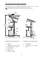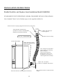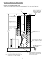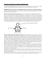
1
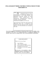
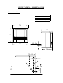
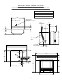
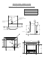
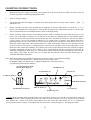
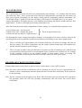
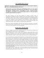
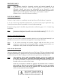
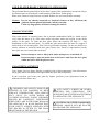
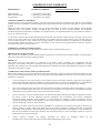
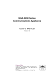
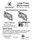
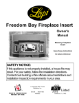
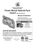
Effective January 2003
INSTALLATION
&
OPERATING
INSTRUCTIONS
Serial Number:
The Australian
Gas Association
Approval No. 4553/AG103
Australian Patent
PN 200110001S
B.D. Number:
Model: IS100
Model: FSP100
Model: FS100
Model: IS200
PLEASE KEEP THESE
INSTRUCTIONS FOR
FUTURE REFERENCE
Model: FSC100
Aurora
CLIMATE SYSTEMS
A.B.N. 43 108 083 987
TABLE OF CONTENTS
SAFETY LABEL
Warranty Installation Service
Safety Labels
OPERATING INSTRUCTIONS
2
Automatic Humidifier Operation
35
3-4
Operating Instructions Checklist
36-37
INSTALLATION INSTRUCTIONS
Specifications
5-6-7-8
General Safety Information
9
Clearances to Combustibles
10
Log Installation
Fluing Requirements
11-12-13
Lighting Instructions
38
Fan Operation
39
Shutdown Instructions
39
High Temperature Cut Out
40
Paint Curing - First Firing
Operating Faults
40
41
Resetting the Heater
41
14
Fluing Options / Installation
15-26
Optional Remote Control Thermostat
27-28
Gas Connection
29
Gas Valve Adjustment
30
Wiring Diagram
31
Safety Screen Installation
32
Insert Surround
33
Optional Pedestal Assembly
34
MAINTENANCE
Maintenance Instructions
42
Log Replacement
42
Main Convection Fan
42
Heat Exchanger
42
Gold/Chrome Plated Doors
43
Glass Replacement/Cleaning
43
SPECIFICATIONS
1
Automatic Flame Safeguard System
44
COMPLETE UNIT WARRANTY
45-47
TO THE NEW OWNER
Congratulations! You are the owner of a state of the art Archer High Efficiency Gas Log Space Heater.
This appliance has been designed to provide you with all the warmth and charm of a wood fire at the flick of a
switch. The Archer Gas Log Space Heater promises to provide you with the highest economy, heat output, comfort
and security.
NOTE: AURORA WARRANTY PROGRAM
Please note to qualify for the Aurora Warranty Program, you need to fill out the warranty registration form, and have
your qualified installer fill out the Installation Commissioning Report. Both documents must be returned promptly to
Aurora Climate Systems.
Under new government legislation, you also need to obtain from your qualified installer, a Certificate of Compliance
for the guarantee of the installation.
Please note, that Aurora Climate Systems will not accept responsibility for faults with the appliance caused through
installation faults. We therefore strongly recommend that you return to Aurora Climate Systems the Installation
Commissioning Report and obtain a Certificate of Compliance from your qualified installer for your protection.
Failure to do so can void your warranty.
Please take a moment now to acquaint yourself with the instructions and many features of your Archer High
Efficiency Gas Log Space Heater.
Warranty - Installation - Service
(Listing and Code Approvals)
This appliance has been tested in accordance with the Australian Gas Association AGA103 Test Approval No.
5445/1996, and has been certified to the Electrical AS.3100 standard.
Check with your local council’s building department to ensure compliance with local codes, including the need for
permits and follow up inspections. Or if you wish clarification of the instructions contained in this manual, please
contact Aurora Climate Systems on telephone (03) 9795 8895 or facsimile (03) 9701 2088.
Note: As the Archer Gas Log Space Heater you have purchased is a high tech, high efficiency
appliance, we wish to advise that your appliance should at all times only be installed by a licensed Gas
Fitter / Installer for the installation and service of the Archer Gas Log Space Heater.
At no time should this appliance be installed outside the installation guide lines contained in the
Installation Manual, or by a non qualified gas fitter / installer. To do so will void the warranty.
It is policy of Aurora Climate Systems that should a fault develop in the Archer Gas Log Space Heater during
its warranty period, Aurora will repair the appliance in these circumstances. However we wish to advise that
should the Archer Gas Log Space Heater develop a fault in its operation because the product was not installed
in accordance with the manufacturer’s guidelines and instructions, or if the product was not installed
correctly by a licensed gas fitter / installer or lack of operating knowledge of the appliance by the customer
causing appliance failure, then a service charge will apply.
In such cases, where attendance is required by Aurora Service Personnel to correct faults in the product which
are not directly related to the product and / or parts failure but are the result of improper installation and lack
of operating knowledge of the appliance, Aurora Climate Systems will charge the purchaser of the
appliance and the installer / service agent a fee calculated on the basis of $80.00 + GST per hour minimum, as
well as travelling expenses in excess of 25 km each way to rectify such faults.
Note: The Complete Unit Warranty, inclusions, exclusions, terms and conditions are listed on pages 49 to 51 of this
manual.
2
PLEASE KEEP THESE INSTRUCTIONS FOR FUTURE
REFERENCE
!
IMPROPER INSTALLATION,
ADJUSTMENT, ALTERATION, SERVICE OR
MAINTENANCE CAN CAUSE INJURY OR
PROPERTY DAMAGE. REFER TO THIS
MANUAL FOR ASSISTANCE OR
ADDITIONAL INFORMATION, CONTACT
AURORA CLMATE SYSTEMS.
TELEPHONE NUMBER (03) 9795 8895
THIS APPLIANCE MUST BE INSTALLED OR
SERVICED ONLY BY A LICENCED GAS
FITTER FOR THE INSTALLATION AND/OR
SERVICE OF THE ARCHER GAS LOG SPACE
HEATER.
Note: If this appliance is installed by a licensed gas fitter who is not familiar on the
installation of the heater, we recommend that prior to installing the appliance the
installer contact Aurora to obtain further advice on the installation of the product.
FOR YOUR SAFETY
What to do if you smell gas?
1)
2)
3)
4)
5)
Open Windows
Turn off main gas supply
Do not touch any electrical switches
Extinguish any open flames
Immediately call your gas supplier
or installer
Do not store or use gasoline or other
flammable vapours and liquids in the
vicinity of this or any other appliance
3
SAFETY LABELS
Model - Archer
Gas Type
Model Type
Gas Consumption
Manifold Pressure
Injector Size - Front
- Rear
A.G.A Approval No
to Code AG103
Electrical conforms to AS3100
Ο
Ο
Natural
FS100 Ο
FSP101 Ο
IS102 Ο
30MjHr
0.8Kpa
1.6mm
2.4mm
5446
LPG
FS100 Ο
FSP101 Ο
IS102 Ο
30MjHr
1.5Kpa
1.1mm
1.5mm
5446
240V 50 Hz
Manufactured by
Aurora Climate Systems
A.B.N. 43 108 083 987
71 - 73 Overseas Drive
Noble Park VIC 3174
To be installed by an authorised person in
accordance with installation instructions
provided with appliance.
80 Watts Max
Serial No:
Date of Manufacture:
Air Pressure switch
Cut in Pressure
Cut out Pressure
Electrical Connection
Cleveland Controls / RSS-495-226
65 Pa
50 Pa
2 Mtr flex standard 3 Pin Plug
Note: In case of power cord damage, replace only with Archer special cord set, obtainable from your Archer
Dealer or direct from Aurora Climate Systems.
!
DO NOT
DO NOT
DO NOT
DO NOT
DO NOT
OPERATE THIS APPLIANCE BEFORE READING THE
INSTRUCTION BOOKLET
PLACE ARTICLES ON OR AGAINST THIS APPLIANCE
STORE CHEMICALS OR FLAMMABLE MATERIALS OR
SPRAY AEROSOLS NEAR THIS APPLIANCE
OPERATE WITH PANELS, COVERS OR GUARDS
REMOVED FROM THIS APPLIANCE
ENCLOSE THIS APPLIANCE
THE GUARD IS FITTED TO THIS APPLIANCE TO REDUCE THE
RISK OF FIRE OR INJURY FROM BURNS AND NO PART OF IT
SHOULD BE PERMANENTLY REMOVED
FOR PROTECTION OF YOUNG CHILDREN OR THE INFIRM, A
SECONDARY GUARD IS REQUIRED
4
SPECIFICATIONS - MODEL NO. FS101/P200
1 Flue Outlet 40mm ø Pipe
Heater with Pedestal and Single Flue Adaptor
2 Air Inlet
3 Electric Cord
4 1/2 “ BSP Connection (Inside)
5 Single Flue Adaptor
45
716
157
443
23
2
1
4
858
3
C/L Flue
409
317
283
323
317
220
697
435
5
SPECIFICATIONS - MODEL NO. FSC100
1 Flue Outlet (Outside 65mm Inside 40mm)
Console Heater and Co-Axial Flue Adaptor
2 Air Inlet
3 Electric Cord
4 1/2 “ BSP Connection (Inside)
5 Air Inlet Cover Plate
30
716
157
443
23
2
1
5
4
858
3
C/L Flue
402
317
283
323
317
792
5
483
SPECIFICATIONS - MODEL NO. FS100
Heater without Pedestal
1 Flue Outlet
2 Air Inlet
3 Electric Cord
4 1/2 “ BSP Connection (Inside)
716
443
638
C/L Flue
706
97
430
157
23
2
1
4
189
3
97
63
6
103
SPECIFICATIONS - MODEL NO. IS100
Fireplace Insert with Mantel surround IS001 (1100 x 858) with standard top panel.
1 Single Flexi Flue Starter Kit
2 Electric Cord
3 1/2” BSP Connection (Inside)
4 Surround (1100 x 858)
706
157
SINGLE FLUE
MANIFOLD STARTER
40MM PVC
C/L Flue
40MM
COUPLING
25
257
161
161
25
257
PVC FLEXIBLE
PIPE
638
608
90º/40MM
PVC ELBOW
150
4
157
1100
1
608
3
103
63
2
250
97
23
858
706
608
706
7
SPECIFICATIONS - MODEL NO. IS200
Fireplace Insert with Mantel surround IS002 (900 x 758) with cut-back top panel.
1 Co-Axial Manifold Flue Starter 65mm
2 Electric Cord
3 1/2” BSP Connection (Inside)
4 Surround (900 x 758)
5 Air Inlet Cover Plate
706
157
C/L Flue
CO-AXIAL FLUE
MANIFOLD STARTER
65MM PVC
25
30
INTERNAL PIPE
40MM PVC
128
290
290
25
5
128
638
608
C/L Flue
97
4
157
900
1
608
150
3
2
63
103
97
758
23
608
706
706
8
INSTALLATION INSTRUCTIONS
GENERAL SAFETY INFORMATION
1.
This installation must conform with local codes or, in the absence of local codes, with AG 601
2.
Provide adequate clearances around the product for servicing and ensure there are no obstructions to the combustion
air intake situated at the back of the heater. (Refer Page 6 item 2)
3.
The appliance must be installed on a flat, solid continuous surface (ie. wood, metal, concrete). Please Note: Rough
or uneven surfaces can cause vibration or humming in the heater.
4.
The Archer Gas Log Space Heater can be installed in a wide variety of ways and will fit nearly any room layout. It
may be installed in a recessed position, framed out into the room, or across a corner. For installation options refer
pages 18 through to 26.
5.
This appliance (Insert and Freestanding Console Models) needs to be installed in such a way that the heater can be
removed at all times to service the heat exchanger and flue fan located in the rear section of the heater.
Note: Under no circumstances should the appliance be installed under conditions, which would not allow
for easy removal of the appliance to carry out routine inspection and service to the appliance, to do
so will void the warranty.
Note: On Single Wall flue pipe installations (imitation zero clearance fireplace) a minimum of 25mm clearance must be
provided at the rear of the heater to enable the heater to get sufficient combustion air to the air inlet located at the
rear of heater. (Refer installation instructions page 6 item 2).
Note: Where a mantel surround is being used on insert installations and imitation zero clearance fireplace
installations, the combustion air intake slot located in the top mantel surround must have no obstructions to allow
combustion air to enter through the slot to the combustion air inlet located at the back of the heater.
!
IN CASES WHERE THE INSTALLATION OF THE HEATER IS
NOT IN ACCORDANCE WITH THE MANUFACTURERS
INSTRUCTIONS AND THE APPLIANCE CAN NOT BE
REMOVED FOR SERVICING IN SUCH CASES WHERE
SERVICE PERSONAL HAVE TO SPEND TIME TO REMOVE
THE HEATER OR CORRECT THE INSTALLATION A
SERVICE CHARGE WILL BE APPLICABLE TO THE
CUSTOMER OF LABOUR AT $80 PER HOUR PLUS GST PLUS
TRAVELING EXPENSES.
!
THIS APPLIANCE SHOULD BE INSTALLED BY A QUALIFIED
LICENSED GAS FITTER.
!
DUE TO HIGH TEMPERATURES, THE APPLIANCE SHOULD
BE LOCATED OUT OF TRAFFIC AND AWAY FROM
FURNITURE AND DRAPERIES.
!
THIS APPLIANCE CAN ONLY BE FLUED IN
ACCORDANCE WITH THE MANUFACTURER’S
INSTRUCTIONS AS TESTED TO AGA CODE 601.
!
FAILURE TO INSTALL THIS APPLIANCE CORRECTLY MAY
CAUSE A SERIOUS HOUSE FIRE.
9
INSTALLATION INSTRUCTIONS
CLEARANCE TO COMBUSTIBLES
Freestanding models FS100 - FSP101
A
B
C
B
C
Freestanding Units
A
Rear Wall to Unit
25mm
B
Side Wall to Unit
15mm
C
Corner Installation
0mm
Fireplace Insert Model IS100
A
B
B
Zero clearance
No hearth required
Note:
The Archer Gas Log Space Heater has been tested and approved for zero
clearance to combustible materials. Aurora Climate Systems recommends that
clearances as listed above should be maintained to allow for removal of the
product for servicing.
For clearances required for Flue Connections refer Pages 17-21-25.
10
INSTALLATION INSTRUCTIONS
LOG INSTALLATION
The gas log set (front/middle log and rear log) is pre-set and installed in the factory. Only the
left and right hand cross logs are packaged separately inside the firebox for installation by
the installer.
1.
To access the log set parcel, lift off top panel and remove the 2 screws in the left hand
and right hand side front panel on the top, which hold the left hand and right hand side
front panel.
2.
Remove panels by lifting panel out and up, place panels in a secure position to avoid
damage to paint work.
3.
Unlatch main door latches located on right hand side of the heater, open door fully.
Carefully remove right hand and left hand cross logs from firebox and remove
cardboard protection from middle logs, and all packaging materials.
Note: Position of rear log and front / middle log has been preset at factory and their
locations should not be changed. Check that logs have not been damaged in transit.
4.
Carefully remove wrapping from right hand and left hand cross logs.
WARNING
5.
!
Front and rear burner inspection.
Prior to positioning of left hand and right hand cross logs inspect front and rear burner
for particle or dust placement on top of burners. If any particles or dust is visible on
top of front or rear burners remove particles before placing cross logs into position.
Note: Ceramic logs are fragile and so to are the hot surface igniters underneath them
and need to be handled with care at all times.
6.
Position left top cross log No (4) in locating slot of front / middle log No (2) and rear
log No (1) (Refer Diagram page 12-13).
7.
Position right top cross log No (3) in locating slot of front / middle log No (2) and rear
log No (1) (Refer Diagram page 12-13).
8.
After left hand and right hand cross logs have been placed in position and safety check
has been carried out, close main door and latch securely with latches located on right
hand side of heater. Please note: the door may need to be lifted slightly on the right
hand bottom corner when closing so that it sits level.
9.
Refit left hand and right hand side front panels with 2 self-tapping screws, and refit the
top panel.
11
INSTALLATION INSTRUCTIONS
LOG SET DIAGRAM - A
The Gas Log Kit contains the following:
1)
2)
3)
4)
Rear Log
Front/Middle Log
R/H Cross Log
L/H Cross Log
4
3
Note: Location Pin has been
fitted to Rear Log (1) to hold
L/H Cross Log (4) in position.
1
2
INSTALLERS - PLEASE NOTE
(A) LOG SETTINGS
Do not remove logs from heater unless absolutely necessary!! Logs have been preset and aligned for
correct performance. Only place cross logs in position as per instructions above.
Please Note: Accurate placement of logs is critical for correct performance of heater.
(B) GAS PRESSURE FOR LPG
Do not adjust gas burner pressure on LPG. Gas burner pressure has been set at factory to required
gas burner settings for LPG.
(C) GAS PRESSURE FOR NATURAL GAS
For Natural Gas please check and adjust gas burner pressure if required as inline pressure can vary in
areas of Australia. For Natural Gas burner pressure settings refer to Page 4.
(D) ADJUSTMENTS
This product has been fully tested for its operation sequences and performance at the factory and no
adjustments should be made, except for the above mention of Natural Gas, to the appliance unless
approved by the manufacturer.
12
INSTALLATION INSTRUCTIONS
(Side view main logs and burners)
1.
Rear Log
2.
Front/Middle Log
3.
Rear Burner
4.
Front Burner
1
2
NOTE:
4
2
3
Do not change position of rear logs and front/middle logs as their positions have been
present at the factory. Changing log positions will result in faulty gas burner function.
13
INSTALLATION INSTRUCTIONS
FLUING REQUIREMENTS
Co-Axial Flue Installations
Note: This appliance has only been approved for co-axial flue application if the flue (as
supplied by the manufacturer) is installed to an external wall or external fireplace.
(Refer installation diagram for Co-Axial Flue Installations Pages 16-17-18-19-24).
Single Flue Pipe/ Single Flexi Installations
Note: This appliance has only been approved for single flue pipe installation if the unit and
flue pipe is installed in line with the manufacturer’s installation instructions (Refer
installation diagram for single flue pipe installations Pages 16-20-21-22-23-24-25-26.
CONFIGURATION 1:
Freestanding Models Pages 15-20-22-23 - Single Flue Application.
SINGLE PIPE 40mm ø 5.1 METRES HIGH WITH 2 x 45° ELBOW.
1 x 90° ELBOW AND ONE 75mm COWL.
CONFIGURATION 2:
Insert Models Page 24-25-26 - Single Flexi Flue Application.
SINGLE PIPE 40mm ø 5.1 METRES HIGH INCLUDING 2 X 45°
ELBOW, 1 X 90° ELBOW, 1m FLEXIBLE PVC SECTION AND
ONE 75mm COWL.
CONFIGURATION 3:
Freestanding and Insert Models for Installation on External Walls or
External Fireplaces Pages 16-17-18-19-24.
CO-AXIAL FLUE INTERNAL PIPE 40MM ø EXTERNAL PIPE
65MM ø BOTH PIPES IN PVC UP TO 1 METRE LENGTH FOR
WALL PENETRATION.
14
SINGLE FLUE KIT FOR ARCHER GAS LOG SPACE HEATER
For applications on Flexible Single Flue refer pages 24-25-26
No
Description
Qty
1
Single Flue Adaptor
1
Supplied with heater
2
40mm ø PVC Pipe 400mm long
1
Supplied with heater
3
90° PVC Bend
1
Supplied with heater
4
40mm ø PVC Pipe
5
Stainless Steel Cowl
1
Supplied with heater
6
Self Tapping Screws 4 x ½"
4
Supplied with heater
Supplied by installer
5
4
6
1
2
3
15
CO-AXIAL FLUE KIT FOR ARCHER GAS LOG SPACE HEATER
For applications refer pages 17-18-19 of this Installation Manual.
No
Description
Qty
1
Co-Axial Manifold Starter
1
2
Internal Pipe Spacers
3
3
40mm ø PVC Pipe
400mm
4
65mm ø PVC Pipe
400mm
5
Stainless Steel Co-Axial Cowl
Approx.
1
2
3
5
2
Mounting Plate
1
4
15mm
Use 4 self tapping screws
provided with assembly
4mm ø x 15mm long.
Note: When connecting 40mm ø and 65mm ø flue pipe to Item 1 co-axial manifold starter
and Item 5 co-axial cowl, do not glue flue pipe connections to allow for removal of flue pipe
for servicing of the heater.
Note: When connecting 40mm pipe at adaptor end and at cowl end, ensure that 40mm pipe is
long enough to fit in securely at both ends. Failure to do so will cause the flames to go
out and the heater will operate incorrectly.
16
INSTALLATION INSTRUCTIONS
Installation External Wall - Including High Rise Apartments
Using Co-Axial Flue Kit
Freestanding Heater without Pedestal Model FS100
For installation details refer Page 16 - Co-Axial Flue Installation
1
5
2
3
C/L Flue
Floor Protection
No Hearth Required
1.
2.
3.
4.
5.
4
97
Installation zero clearance to combustibles.
Note: Allow 30mm for clearance to rear wall for Co-Axial Flue Adaptor.
65mm PVC Co-Axial flue pipe up to 1 metre long - Refer page 16
Co-Axial Cowl
1/2” BSP Gas Connection (Inside) Left hand front side panel
Air Inlet Cover Plate
NOTE: Do not use PVC cement to seal flue pipe connections to allow for removal of flue pipe.
17
INSTALLATION INSTRUCTIONS
Freestanding Model with Pedestal Installation FSP101
- External Wall including High Rise Apartments using Co-Axial Flue Kit
For installation details refer Page 16 - Co-Axial Flue Installation
1
5
2
3
C/L Flue
4
317
Floor Protection
No Hearth Required
1.
2.
3.
4.
5.
Installation zero clearance to combustibles
65mm PVC Co-Axial flue pipe up to 1 metre long - Refer page 16
Co-Axial Cowl
1/2” BSP Gas Connection (Inside) Left hand front side panel
Air Inlet Cover Plate
NOTE: Do not use PVC cement to seal flue pipe connections to allow for removal of flue pipe.
18
INSTALLATION INSTRUCTIONS
Insert Models IS100/IS200
-With Co-Axial Flue - Exterior Masonary Fireplace
For Installation instructions refer Page 16 - Co-Axial Flue Installation
Co axial Flue Pipe up to 1 metre long
Refer Page 16
1/2” BSP Gas Connection
Refer Page 29
Note: Do not use PVC cement to seal flue pipe connections to allow for removal of flue
pipe. Incorporate loop in gas connection or use flexible hose for gas connection to allow for
removing of appliance from fireplace.
19
INSTALLATION INSTRUCTIONS
Freestanding Unit Installation - with Single 40mm PVC Flue Pipe using 75mm Cowl
For External and Internal Wall Applications
(Flue Kit Assembly is supplied complete - under Stock Order Code SFA001)
Correct Installation
Incorrect Installation
Correct: Cowl to suit
40mm PVC Flue Pipe
supplied in flue kit
SFA001.
40mm PVC Flue Pipe to be
supplied by installer.
Correct: 40mm PVC
Flue Pipe to have
upward slope to avoid
water trap in 90°elbow.
Union Flange attached
to heater's exhaust fan
supplied and fitted to
heater.
Correct: Fasten 40mm
PVC Flue Pipe with
bracket to stop flue pipe
being forced downward.
(Supplied by Installer)
x
15mm
x
x
x
Correct:Connect 40mm flue pipe
to coupling supplied with
appliance.
NOTE:
Correct: For safety install gas
cock close to appliance.
All flue pipe connections need to be sealed with PVC cement, except Flue Fan Connection.
20
INSTALLATION INSTRUCTIONS
Freestanding Internal Wall Installation Models FS100 - FSP101
- Using Single 40mm ø PVC Flue Pipe
For External and Internal wall applications
Freestanding Models with and without Pedestal
Refer Page 20 for correct installation instructions
2
3
500mm
Roof
4
5100mm MAX
Internal Wall
5
NOTE:
All flue pipe
connections need to be
sealed with PVC cement,
except connection of
40mm ø pipe item 7 to
flue fan outlet.
150mm
80mm
6
1
1.
2.
3.
4.
5.
6.
7.
7
327mm
40mm ø flue adaptor with coupling fitted and supplied by manufacturer
75mm stainless steel cowl to suit 40mm PVC Flue Pipe (supplied in flue kit SFA001)
Flashing - to be supplied by installer
45º Elbow - to be supplied by installer
40mm PVC Pipe - to be installed by installer
90º Elbow - supplied by manufacturer
Horizontal flue pipe 300mm approximately supplied by manufacturer
21
INSTALLATION INSTRUCTIONS
Internal to External Wall Installation using 40mm ø PVC Flue.
Side Wall Installation
(Horizontal Single Flue)
External Wall
Internal Wall
90º Elbow
75mm stainless steel
cowl to suit 40mm
PVC flue pipe.
Gas Line
Concrete Slab
CAUTION:
40mm PVC Pipe
PLEASE DO NOT ALLOW WATER
TRAPS TO FORM IN FLUE OR
HEATER WILL CEASE TO OPERATE.
Note: Total installation length in 40mm ø PVC pipe 5100mm
with 1 x 90º and 2 x 45º bends.
22
INSTALLATION INSTRUCTIONS
Internal Wall Under Floor Installation using 40mm ø PVC Flue.
Internal Wall
External Wall
90º Elbow
75mm stainless steel
cowl to suit 40mm
PVC flue pipe.
90º Elbow
Note: All flue pipe connections need to be sealed with PVC
cement, except Flue Fan Connection.
Note: Total installation length in 40mm ø PVC pipe 5100mm
with 1 x 90º and 2 x 45º bends.
Caution:
To avoid water trap in Flue system 40mm ø PVC pipe
must be supported every 2 metres to avoid PVC pipe
sagging, and PVC pipe must have fall to ground level
(see sketch).
Caution:
If a water trap develops in the flue the heater will cease
to operate or could soot up.
23
CREATED FIREPLACE MODEL IS100/IS200
Zero clearance, power flue, single 40mm flue and shallow unit depth allow you to create
your own fireplace anywhere in your home with your choice of mantel.
Note: Heater must be able to be removed easily for servicing. (Not locked in)
1
2
500mm
6
5
5100mm
Maximum
4
4
7
9
8
1
2
3
97mm
97mm
3
INTERNAL WALL APPLICATION
EXTERNAL WALL APPLICATION
1.
2.
3.
4.
5.
6.
7.
8.
9.
1.
2.
3.
4.
75mm Cowl
Flashing
½" BSP Gas Connection (Flexible)
40mm PVC Pipe Zero Clearance
45° PVC Elbow
45° PVC Elbow
Mantel
Flexible PVC Pipe
40mm PVC Coupling
24
Co-Axial Flue
Co-Axial Cowl
½" BSP Gas Connection (Flexible)
Mantel
INSTALLATION INSTRUCTIONS
Flexible Flue Kit to suit Fireplace Insert Installations Model IS100/IS200
STANDARD FLUE KIT SUPPLIED BY AURORA FOR INSERT INSTALLATION (SFA002)
Note: Standard 75mm Cowl to fit 40mm ø pipe is also supplied with flue kit.
40mm N.B. Plain Coupling (Supplied with Flue Kit) (38mm I.D.)
50mm Nylaflow Flexible Hose
Nylaflow G.P. Hose Code AH50WAS
(Supplied with Flue Kit SFA002)
40mm N.B. SWV Pipe
(Not Supplied)
60mm S.S. Hose Clamp
Note: I.D. = Inside Diameter
Archer Inbuilt Heater
Flange attached to heater’s
exhaust fan (Supplied and
fitted to heater)
Note: If adaptor not fitted drill
4 holes 3mm ø use mounting
plate as template.
Caution: Only drill holes
through outer casing. Use 4
self-tapping screws 4mm ø x
15mm supplied with assembly.
40mm N.B. x 90º Elbow
38mm I.D. (Supplied with flue kit)
150
40mm N.B. Barrel Union (Supplied with flue kit)
25
Note: 150mm clearance required for Flue
Adaptor.
INSTALLATION INSTRUCTIONS
Fireplace Insert Installation Model IS100
-Using Aurora Flexible Flue Kit SFA002 with Single 40mm PVC Flue Pipe using 75mm cowl
Fasten 40mm Flue Pipe with
bracket to stop flue pipe
being forced downwards
( Supplied by Installer)
Gas Cowl Supplied
in flue kit
200mm
Galv Sheet Flashing
to seal chimney
(Supplied by Installer)
40mm PVC Pipe SWV
(Supplied by Installer)
2 x 45º PVC bends 40mm
(Supplied by Installer if
required)
5100mm
MAX
Aurora flexible flue kit
SFA002
Use 1/2” gas loop or part loop
in 1/2” copper pipe to allow
unit to be removed and
serviced or use flexible gas
hose for gas connection
For safety install gas cock
next to appliance
Note: All flue pipe connections need to be sealed with
PVC cement, except Flue Fan Connection.
Note: Total Installation length in 40mm ø PVC pipe
5100mm with 1 x 90º and 2 x 45º bends.
26
Note: Do not allow elbow to sag downwards.
If it does a water trap will develop and
heater will cease to operate.
OPTIONAL REMOTE CONTROL THERMOSTAT
An optional programmable Remote Control Thermostat can be fitted to the heater at the factory when
ordered or even after the heater has been installed. See your Archer dealer for correct type.
Installation:The Remote Control can be installed by the owner of the heater if required. The Remote
Control is a battery operated device, which requires a small amount of low voltage plug in wiring. A
wiring loom package is supplied by Aurora Climate Systems, which simply plugs onto the front panel
and the red button. Refer Page 28.
Remote Control Operation/Programming: Refer to the instruction sheet supplied with the device.
Note: Aurora Climate Systems is not the manufacturer of any Remote Control Thermostats and will
charge a service fee to the customer who requires a technician to be on site to give operating
instructions, installation, set up or programming. If the device appears to be faulty it will need to be
posted back to Aurora Climate Systems where the functionality will be checked and returned back to
the customer in working order. Aurora Climate Systems recommends that the customer familiarise
themselves with the Remote Control Thermostat operation through reading the instructions supplied
or by requesting that the installer of the appliance commissions the Remote Control Thermostat.
Economy Display Mode Button
Front Burner
Rear Burner
Operator Switches
Economy Display Mode (Red Button Operation): The red button above the two burner switches is
called the economy display mode and will only function when a Remote Control Thermostat has been
installed in the heater. The most common way this button is used is having the Remote Control set on
the Thermo mode with a desired temperature set for the heater to cut in and out, which will of course
be relevant to the ambient temperature, location and the area the appliance is positioned in. When using a Remote Control Thermostat both burner switches need to be in the on position. When the red
button is pressed to be illuminated in conjunction with having both burner switches on, the front
burner only will commence ignition and then remain on or if already alight it will now remain on, regardless of what function or temperature is set on the Remote Control.
In this situation only the back burner will cut in and out according to the setting on the Remote
Control. We believe by running the heater this way you will use less gas and still have the ascetic
affects of the front burner. However if the appliance is in a small area this may get to warm for you.
All you need to do then is press the red button so that it is not illuminated and the heater will then
revert back to its normal operation.
In basic terms the red button acts as a Remote Control override switch for the front burner only. Also
the Remote can switch the heater on and off in the high setting, medium setting or low setting. Refer
Page 38 - Burner Settings.
Note: When the heater or the Remote Control is not being used for long periods the burner switches
should be in the off position, also in summer the heater should be turned off at the power point.
27
ARCHER GAS LOG SPACE HEATER
INSTALLATION OF THE REMOTE RECEIVER AND
FRONT FLAME DISPLAY BUTTON
Effective 13th April 2005
VIOLET
Caution: Please make sure heater is unplugged when installing
Remote Control
Please Note: The front panel must be opened for this wiring to occur.
The front panel simply pulls forward - no tools required.
RED
BUTTON
Caution when removing front panel as there are low voltage wires
attached to the inside of the front panel.
INSTALL WIRING
LOOMS
YELLOW
P2
WHITE
REMOVE LINKS FROM T1,
T2 AND P2 AND PLUG IN LOOM
P2
BLACK
T2
T2
RED
T1
T1
J5
DISPLAY PANEL
BLACK
WHITE
PLEASE DO NOT REMOVE ANY
EXISTING WIRING FROM THE
DISPLAY PANEL
LOOM
FLAT RIBBON CABLE
TO CONTROL BOX
(ALREADY FITTED)
BLACK
RED
BLACK
RECEIVER
PLACE RECEIVER IN
HEATER BETWEEN PUMP
CONTAINER AND
PRESSURE SWITCH.
CONNECT THIS WIRE TO THE BODY OF THE
HEATER TO MAKE THE EARTH CONTACT.
FOR EASY ACCESS USE THE SCREW AT THE BASE
OF THE FAN.
NOTE: PLEASE KEEP LINKS FROM T1 & T2 INSIDE THE HEATER FOR
FUTURE BRIDGING IF REQUIRED.
28
INSTALLATION INSTRUCTIONS
GAS CONNECTION (Line Supply)
The gas connection is 1/2” BSP supplied in heater.
GAS SUPPLY LINE TO HEATER
a)
b)
c)
d)
e)
Remove top panel from heater by lifting top panel.
Remove the 2 screws on top L/H front side panel and lift out side panel.
Remove rubber grommet from back panel of heater and insert 1/2” copper gas supply line through
back panel of heater.
Connect gas supply line to flexible gas hose. Ensure that flexible gas hose is not kinked after fitting
gas supply line.
After gas supply line has been brought through from rear of heater, place rubber grommet supplied
over gas line and insert into back panel.
Note: The copper gas supply line to the heater must be installed under conditions which will allow for
easy removal of the heater from its location for servicing of the heater. For fireplace insert installations,
incorporate either a copper loop into the supply line or flexible hose being used for the gas supply to the
heater to allow for easy removal of the appliance.
Note: Under no circumstances should the gas supply line to the appliance be installed under conditions,
which would not allow for easy removal of the appliance to carry out routine inspection and service to the
appliance.
29
INSTALLATION INSTRUCTIONS
GAS VALVE PRESSURE ADJUSTMENT
The gas valve pressure adjustments must be checked during installation, and if necessary
corrected to suit the gas type available. (Reference Page 12)
“A” represents the main regulator adjusting screw pressure to burners. Access to this screw is
obtained by removing the brass screw cover; use a flat blade screw driver for
adjustment of gas pressure. Note: Gas burner pressure can only be adjusted on high
burner setting with both switches medium and low burner in the “ON” position and flame
holding on both burners.
“B” represents the test point for connecting the manometer. Gas Valve is supplied with
brass test tube for connecting the manometer. Note: To obtain reading of gas burner
pressure, open the brass screw located inside test point with a small blade screw driver,
before connecting the manometer to test tube. On completion of checking burner
pressure, tighten the brass screw inside the brass test tube.
A
B
30
ARCHER 2004 WIRING DIAGRAM 240V 50 Hz
TRANSFORMER 240V
240 V ACTIVE BROWN
EARTH
GREEN
CONVECTION FAN
(2) TR.PRIMARY BLACK
TR.PRIMARY WHITE (8)
240 V NEUTRAL BLUE
J1
NEUTRAL ( 7-5-3 )
PIN 18
HSI
HSI
PIN 16
0.47 uF
PIN 6
1 uF
PIN 4
F
OVER TEMP .80 C
R
FRONT AND REAR GAS VALVES M 25
1
0
FRONT BURNER SWITCH
PIN 5
14 WAY RIBBON TO DISPLAY
PIN 20
CONV.FAN.BLACK ( 13 )
(1) CONV.FAN.BLUE
MAIN GAS VALVE E 8
REAR.H.S.I.
(19)
(20) GAS.VALVES.ACTIVE
FRONT.H.S.I.
(17)
(18) REAR.H.S.I.
LOW.SPEED.CAP.
(15)
(16) FRONT.H.S.I.
CONV.FAN.BLACK
(13)
(14) MAIN GAS VALVE
MEDIUM.SPEED.CAP
(11)
(12) INDUCTION.FAN
F.GAS.VALVE.NEUTRAL
(9)
(10) WATER.PUMP
R.GAS.VALVE.NEUTRAL
(7)
WATER.PUMP
(5)
INDUCTION.FAN
(3)
OVER TEMP .80 C
INDUCTION FLUE FAN
PIN 3
PIN 5
(8) CONV.FAN.BROWN
(6)
(4) MEDIUM.SPEED.CAP
J2
N.C. (1)
LOW.SPEED.CAP.
0.47 uF
1 uF
1
J5
P1 BLACK TO DISPLAY
THERMISTOR CONVECTION FAN SPEED
0
REAR BURNER SWITCH
F.BRN.SW.N.O.
(2)
R.BRN.THERM
(4)
(1) R.BRN.SW.N.O.
J3
(3) F.BRN.THERM
FAN.SPEED. SENSOR
(6)
(5) F.BRN.SW.N.C.
FAN.SPEED. SENSOR
(8)
(7) R.BRN.SW.N.C.
F.BRN.SW.COMM
(10)
(9) R.BRN.SW.COMM
REAR.FLAME.SENSOR
(12)
(11) AIR.PR.SW.COMM.
FRONT.FLAME.SENSOR (14)
(13) AIR.PR.SW.N.O.
FLAME GROUND. BLACK(16)
(15) AIR.PR.SW.N.C.
PUMP FAIL
P1 WHITE TO DISPLAY
(3)
(2)
(1)
(1) N.C.
RED (2)
WATER SENSOR
FLAME SIGNAL GROUND
CONDENSATE PUMP
(2) MAIN GAS VALVE
J4
(4)
AIR PRESSURE SWITCH
(3) WATER SENSOR
(5) 12V AC YELLOW
12V AC YELLOW (6)
TRANSFORMER 12V
FLAME SENSOR RODS
OPTIONAL
RADIO THERMOSTAT
WATER SENSING SWITCH
WHITE
14 WAY RIBBON
P1
P1
T1
T2
DISPLAY PANEL 8 L.E.D.s
BLACK
F.BRN.THERM (3)
R.BRN.THERM (4)
T1
WHITE
RED
T2
BLUE
BLACK
WHITE
BLACK
U.H.F.
RECEIVER
BLACK
RED SWITCH
P2
WHITE
P2
FRONT FLAME DISPLAY FUNCTION —- LOOM P2 TO BE ADDED WITH EXTERNAL THERMOSTAT ONLY.
YELLOW
VIOLET
31
INSTALLATION INSTRUCTIONS
MAIN DOOR SAFETY SCREEN INSTALLATION
!
CHILDREN AND ADULTS SHOULD BE ALERTED TO THE
HAZARDS OF HIGH SURFACE TEMPERATURE FROM THE
MAIN DOOR GLASS AND SHOULD STAY AWAY TO
AVOID
BURNS OR CLOTHING IGNITION. YOUNG
CHILDREN SHOULD BE CAREFULLY SUPERVISED WHEN
THEY ARE IN THE SAME ROOM AS THE APPLIANCE.
ALWAYS ENSURE THAT YOUR SAFETY SCREEN
SUPPLIED WITH THE HEATER IS FITTED TO THE MAIN
FRONT DOOR OF THE HEATER.
!
ANY SAFETY SCREEN OR
GUARD REMOVED FOR SERVICING AN APPLIANCE
MUST BE REPLACED PRIOR
TO OPERATING THE
APPLIANCE.
32
INSTALLATION INSTRUCTIONS
Heater surround Fireplace Insert Installation
1.
Remove Fireplace Insert Surround assembly from carton, handle insert surround with care
to avoid paint damage.
2.
Assemble Fireplace Insert Surround as per diagram with 4 of 8 gauges x 3/8” self-tapping
screw supplied.
Insert Heater Surround (Front View)
Combustion Air Intake Slot
Insert Heater Surround (Rear View)
Mantle Top
Combustion Air Deflector
4 of 8 gauge x 3/8”
Self-Tapping Screws
MANTLE SIDE
33
INSTALLATION INSTRUCTIONS
Optional Pedestal Assembly Installation
1.
2.
3.
Remove pedestal assembly from carton. Handle pedestal with care to avoid paint damage.
Place pedestal assembly into position where heater is to be located.
Lift and place main body of heater on top of pedestal assembly and locate main body of
heater into locating points provided on pedestal assembly. (Refer diagram)
NOTE: To avoid accidents and damage to main heater body and paintwork, it is recommended
that main body of heater should be located on top of pedestal assembly by 2 people.
4.
Secure pedestal assembly to main body of heater with 3 M5 x 8mm screws supplied. (Refer
diagram)
Screw Location
Locating Points
Screw Location
Note:
Use 3 M5 x 8mm screws and washers provided to secure pedestal
assembly to base of heater.
34
Screw Location
AUTOMATIC HUMIDIFIER OPERATION
Most gas heaters dry out the air in the room.
(Remember the bowls of water in front of the old gas
heaters?) The Archer has ingeniously solved this
problem with an Automatic Humidifier. Gas contains
moisture which is normally expelled out the flue or
chimney after combustion. But the Archer is so
efficient by taking 92% of the heat out of the burnt
gases that the moisture drops out and condenses in the
back of the heater. This water is collected in a tank
which is then pumped up to a stainless steel holding
tank, where it evaporates in the stream of hot air
which is blowing into your home. Air humidity is
automatically restored!
1.
The amount of condensate build up in the water sump is dependent on outside
temperature, length and height of the flue pipe. The automatic humidifier can operate
approximately anywhere from between every 10 minutes to every 6 hour intervals,
depending on ambient temperature, style and type of flue. Long single vertical flues
can cause the humidifier to come on more often depending on heater settings.
2.
When the automatic humidifier is engaged and is transferring the condensate into the
stainless steel tray, a hissing sound may be noticeable. This occurs when the
condensate enters the stainless steel holding tank and is quite normal. The duration of
the sound may vary from 3 to 30 seconds until the stainless steel holding tank has been
filled with the condensate.
3.
When the automatic humidifier pump comes on to pump condensate into the stainless
steal tray (located on the top of the heater), the L.E.D light (Item 10) on the front
panel will light up and flash for the duration of the condensate pump operating, and
then extinguish after the pump has stopped operating. This means water has been
pumped into the tank, and automatic humidification will commence.
35
OPERATING INSTRUCTIONS CHECKLIST
BEFORE OPERATING THIS APPLIANCE, CAREFULLY
PROCEED THROUGH THE FOLLOWING CHECK LIST.
1.
Read and understand these instructions before installing or operating this
appliance.
2.
Installation of this appliance is only to be carried out by a licensed gas fitter who
preferably should be familiar with the installation of the Archer Heater.
3.
Installers who are not familiar with the installation of this appliance should
contact Aurora Climate Systems prior to installing the appliance to avoid
creating hazardous operating conditions.
4.
No deviations on installation are allowed, unless they are specifically approved in
writing by the manufacturer of the appliance.
5.
Wrongful or deviations taken by the installers on the installation of this
appliance, will result in the heater not starting up or operating incorrectly
causing a safety hazard and will void the manufacturer’s warranty of the
appliance.
6.
Check and inspect the appliance for gas leaks. In the event of gas leaks, cut off the
gas supply to the heater immediately and call your gas supplier or installer.
7.
Check and verify that all flue venting combustion air intakes and flue cowl are
unobstructed.
8.
Refer to page 15 for Single Flue pipe and page 16 for Co-Axial Flue installations,
that correct flue pipe and cowl has been fitted in line with the manufacturer’s
specifications as illustrated in the Installation Manual Pages 15 to 26.
9.
Do not use alternative Flue or Cowl on installation other than that specified in
this manual - otherwise heater will malfunction and cause hazardous operating
conditions and will void the manufacturer’s warranty.
10.
Check and verify that flue pipe connection to the appliance when using single
40mm flue pipe installation is correctly installed and secured in line with
instruction in the Installation Manual Pages 20 to 26.
36
OPERATING INSTRUCTIONS CHECKLIST cont...
11.
Prior to operating the appliance check for dust or particles lying on top of the
burners. Refer Page 11 item 5.
12.
Check and verify that logs are placed correctly as per instructions on
Pages 12-13 of this Installation Manual. If logs are incorrectly positioned or
placed wrongly it can create a hazardous situation, and in most instances, the
heater will not operate correctly.
13.
Do not light heater without logs fitted, as heater will not operate.
14.
For your personal safety, check and verify that polarities are correct in the
power supply to the heater. Also check for proper earth connections at the
power source. If polarities in power supply are incorrect, change the polarities
in the power supply to heater, NOT in the heater cord. Incorrect polarity’s
will cause the appliance not to function correctly.
15.
Check and verify prior to starting up the appliance, that all panels are secured
in place and that the main door has been locked in position.
16.
After verifying and checking all the above points proceed to lighting
instructions. Refer page 38.
37
LIGHTING INSTRUCTIONS
1.
Main Electrical power supply must always be switched on to the unit with the two burner switches in the off
position (up) before commencing lighting the heater.
2.
Turn on main gas supply.
3.
Verify that main electrical supply is switched on by checking the 240V AC power status display
indication is on.
4.
Burner selection: select low burn, medium burn, or high burn. Low burn switch (Item 1) controls the f r o n t
burner only. Medium burn switch (Item 2) controls the rear burner only. When both switches are down, they
will activate both the low and medium burners, which is the high setting.
5.
Heater operating LED sequence (Front Display Panel). Before commencing ensure that the power L.E.D
(Item 3) is on and burner switches are off. Switch on the heater by engaging the low and medium burner
switch, this will activate the pressure switch and the flue fan L.E.D (Item 4) will be on. Also the two burner
L.E.D’s (Items 5 & 6) will commence flashing for 35 seconds prior to ignition. Once both burners have
ignited the burner L.E.D’s will remain on. If you cant see flame on the rear burner, but the burner L.E.D is on
then there will be flame there, which will become more visible as the heater warms up. Once the heater warms
up the low speed L.E.D (Item 7) will light and the convection fan will blow warm air from the heater, as the
heater becomes warmer the medium L.E.D (Item 8) will come on and when the heater has reached its highest
operating temperature all three L.E.D’s (Items 7, 8 & 9) will light up and the convection fan will now be
running at its high speed. Refer Page 39 - Fan Operation. When the heater has been running for some time, the
water pump L.E.D (Item 10) may come on to signal that the pump has been activated. Refer Page 35 Automatic Humidifier Operation.
(Item
3)
Note: Three heat settings are available for operating your Archer heater - low, medium and high.
a) Low setting (front burner only) - engage low burn switch only (Item 1)
b) Medium setting (rear burner only) - engage medium burn switch only (Item 2)
c) High setting (front and rear burners)
Thermostat Display Mode
Button (Refer Page 27)
Back Burner (6)
Front Burner (5)
Low Burn Switch (1)
Flue Fan (4)
High Speed (9)
Medium Speed (8)
Medium Burn Switch (2)
240V AC Power (3)
Low Speed (7)
Water Pump (10)
Caution: When switching from the front burner to the rear burner, be sure to activate the rear burner first , then turn
off the front burner. When switching from the rear burner to the front burner, be sure to activate the front burner
first. Simple rule - always activate the desired burner first, then switch the other burner off. If it is switched the
wrong way the burner/s will go out and the heater may need to be reset. Refer Page 41 - Resetting the Heater.
38
FAN OPERATION
The 3-speed main convection fan will cut in automatically approximately 3 to 5 minutes after the heater
has warmed up. Note: The 3-speed main convection fan is automatically controlled and will operate on
three preset speeds. Depending on your burner setting and the surrounding ambient temperature, the
L.E.D lights (Items 7, 8 and 9) for the fan will light up. The bottom L.E.D light (Item 7) is low speed
setting, and middle L.E.D lights (Item 8) is the medium speed setting, the bottom, middle and top L.E.D
lights (Items 7, 8 and 9) is the high-speed setting (both burners on).
Note: The fan will operate totally independent of burner setting - it is controlled by temperature only.
a) Front burner only - low fan speed
b) Rear burner only - medium fan speed
c) Both front and rear burners - high fan speed
These are approximates only
On changing the burner setting from high to medium, or from high to low, there will be a delay on the
operating speed of the fan until the firebox has cooled down sufficiently for the fan to change speed.
1.
Note: It can take up to approximately 20-30 minutes before the fan speed will change and settle on
the next setting. The firebox temperature and the outside ambient temperature will regulate how
quickly the fan responds to speed changes.
2
Note: It is quite possible if the room the heater is in starts to reach an ambient of 30°C that the main
convection fan could turn itself on even though the heater or burners are switched off. An example
of this occurring would be in the summer months or from another source of heating. We
recommend if this is occurring that the heater should be turned off at the power point.
HEATER SHUT DOWN INSTRUCTIONS
Turn medium burner switch (Item 2) and low burner switch (Item 1) to the “OFF” position.
Note: The main convection fan in the heater will be operating on and off for up to approximately 45
minutes or more. intermittently until the firebox has been cooled down sufficiently for the main fan
to stop operating.
Note: Do not cut main electrical supply to the heater after the heater has been switched off to stop main
fan operating. Main fan will stop operating automatically after the heater has cooled down
sufficiently.
39
OVER TEMPERATURE CUT OUT
The Archer Gas Log Space Heater is protected against overheating with a high temperature 80° cut out
switch to protect the heat exchanger, plastic sump and flue fan.
The high temperature cut out switch will automatically switch off the gas supply to the heater, if the
temperature in the room where the heater is located reaches approximately 28°C. The heater will go into
lock out mode. An allowance of 15 minutes minimum must be made to allow for the main fan to cool
down the heater prior to restarting the appliance.
Note: In most instances, overheating of the heater is a direct result of too much lint and dust having
accumulated in the main convection fan. This means the fan won’t be able to supply sufficient air to cool
down the heat exchanger. It is recommended that you inspect your main convection fan prior to
commencement of the heating season and if necessary have it serviced by a qualified service technician
(refer page 42 –Maintenance).
PAINT CURING - FIRST FIRING
The first fire in your heater is part of the paint curing process. Your Archer Gas Log Space Heater has
been painted with the highest quality heat resistant silicon paint available in the world.
The temperature this paint can withstand before it breaks down and burns off is around 800°C, which is
well in excess of the heater’s normal operating temperature.
To ensure that the paint is properly cured light the unit and leave it burning on high burn for
approximately 1 hour.
1. Ventilate the house during the first time the heater is being operated. The paint on the heater and the
main door glass seal will give off light smoke with carbon dioxide and has an odour. Without adequate
ventilation, concentrations of smoke could irritate, or be upsetting, so ensure you have adequate
ventilation. After the initial first burn, the paint will be cured and there should be no more smoke.
2. Don’t touch the surface of the heater. It will be soft during this paint-curing phase. Once cured it will
not be soft again.
3. The paint finish of the heater should not be cleaned with any caustic or abrasive cleaning solutions
4. Any damage to painted surface should be repaired with special touch paint available from your Archer
Dealer.
40
UNIT OPERATING FAULTS
SERVICE AND INSTALLATION OF THE APPLIANCE SHOULD BE CARRIED
OUT BY AUTHORISED PERSONNEL ONLY.
THE MAJOR CAUSE OF OPERATING PROBLEMS WITH GAS LOG SPACE
HEATERS IS IMPROPER GAS PRESSURE, INCORRECT LOG PLACEMENT,
IMPROPER INSTALLATION, INCORRECT FLUE INSTALLATION,
INCORRECT SWITCHING OF BURNERS, DIPS/SPIKES IN THE INCOMING
POWER OR REVERSE POLARITY’S.
The above situations can cause such problems as changes in flame colour or
configuration, intermittent operations, changes in heat output, carbon build up or sooting,
bad odours, rattles or other sounds, start up failures and burner/s switching themselves
off. These are nearly always the result of improper installation or incorrect operation and
it may take sometime for these problems to show themselves. Before calling out a
technician you must be able to repeat the fault. If not a service charge will apply. One
should always in the event of a fault try resetting the heater. Read below.
Please Note: Incorrect installation of the unit, logs, flue pipe, gas pressure or operation,
which cause the above mentioned faults, are not covered under warranty and a service or
call out fee will be charged to correct such problems.
RESETTING THE HEATER
There are a number of reasons why sometimes the heater will switch itself off and is the
correct thing for the heater to do in certain situations.
Eg. Overheating, power failure or dips, windy conditions, pump failure, partial or full
blockage of flue pipe or no gas. All of these operations are monitored by the electronic
control box inside the heater, which is heat sensitive, pressure switch sensitive, flame
sensitive and water sensitive. If one of these items is not correct it will shut itself down.
To reset turn both burner switches in the off position, ensure the red button above the two
burner switches is not illuminated. (If a Remote Control is fitted have it in the off mode)
Then turn the power off at the power point for approximately 10 seconds. Then turn the
power point back on and the power L.E.D should be illuminated. If you have a Remote
Control fitted it should be switched to the on mode. Now switch down the right hand
burner switch and the rear burner L.E.D should start flashing, with the flue fan L.E.D
remaining steady. Now wait approximately 60 seconds for the rear burner to ignite. You
can tell when it has lit, even if you cant see any flames, by looking at the rear burner
L.E.D which should remain steady. Now repeat the same process with the front burner.
Turn on the front burner switch and wait approximately 60 seconds and the front burner
L.E.D will remain steady.
Then in approximately 5 minutes the convection fan should start and the heater has been
successfully reset. Note: if the heater is still warm when reset the convection fan may
already be running when the unit is powered up.
41
MAINTENANCE
Note:
Your appliance should be inspected, serviced and checked annually by a
qualified service person to ensure that your appliance is operating safe and
efficiently. Should you detect any abnormality in the operation of your
appliance call a qualified service person who has been trained and approved to
inspect and service the appliance. This may be your installer or dealer.
(Routine service is not covered under warranty)
LOG PLACEMENT
Cracks in a log’s surface or crumbling is normal and do not affect the heater’s operation.
If for any reason a log should need replacement, you must use the proper replacement log.
Consult your Archer dealer for purchase of correct replacement logs.
Replacement logs must be installed and positioned as outlined on pages 11-12-13 under Log
Installation.
Note:
Improper positioning of logs will create carbon build up and will alter the unit’s
performance and operation, which is not covered under warranty.
MAIN CONVECTION FAN
The main convection fan in the heater should be checked, serviced and cleaned annually by a
qualified service person to ensure that your appliance is operating efficiently.
Note:
If the main convection fan becomes clogged with lint and dust an over
temperature situation will occur through the heater exchange system and the over
temperature safety switch will stop the heater from operating.
HEAT EXCHANGER
The heat exchanger of the unit is located at the rear of the heater. The heat exchanger should
be inspected annually by a qualified service person for lint and dust build up. Excessive dust
and lint build up in the heat exchanger can alter the unit’s performance and operation.
Note:
This appliance (Insert and Freestanding Models) needs to be installed in
such a way that the heater (especially with models built into a fireplace) can
be removed at all times to service the heat exchanger and flue fan, which are
located at the rear section of the heater.
Under no circumstances should the appliance be installed under conditions
that would not allow for easy removal of the appliance to carry out routine
inspection and service work on the appliance. The warranty will be void if
access or easy removal is not available.
!
DISCONNECT MAIN POWER
PRIOR TO COMMENCING ANY
WORK ON THE APPLIANCE.
42
GOLD PLATED DOOR/ CHROME PLATED DOORS
The gold and chrome plated finish on the door requires little maintenance and needs only to
be cleaned with a soft cloth and a small amount of Mr Sheen. Polish gently.
Please note: Stains or imperfections on plated finishes are not covered under warranty.
Caution: Do not use abrasive materials or chemical cleaners as they will harm the
gold and chrome plated finish and void the warranty.
Clean any fingerprints off before turning the unit on.
GLASS CLEANING
After some period of operating time, due to normal condensation build up, which occurs
every time the heater is lit, some water marks and other stains may appear on the inside
surface of the glass. To clean the door glass follow the sequence on Page 11 - Log
Installation to open the main door. To polish the glass and remove the haze we suggest a
moist cloth or car cut and polish. This is not covered under warranty. Do not use abrasive or
caustic solutions to clean the main door glass. Please note: Stains or imperfections on the
door glass are not covered under warranty.
Caution: Do not attempt to remove side panels unless main power is switched off.
Do not attempt to open the main door of the heater and clean the door glass
whilst the heater and the glass are hot.
GLASS REPLACEMENT
Your Archer Gas Log Space Heater is supplied with a high temperature 5mm Neoceramic
safety glass that will withstand the highest heat that your unit will produce.
In the event that you break your glass by impact, purchase your replacement from an
authorised Archer dealer only.
! CHILDREN AND ADULTS SHOULD BE
ALERTED TO THE HAZARDS OF HIGH
SURFACE TEMPERATURE AND SHOULD
STAY AWAY TO AVOID BURNS OR
CLOTHING IGNITION. YOUNG CHILDREN
SHOULD BE CAREFULLY SUPERVISED
WHEN THEY ARE IN THE SAME ROOM AS
THE APPLIANCE. ALWAYS ENSURE THAT
YOUR SAFETY SCREEN SUPPLIED WITH
THE HEATER IS FITTED TO THE MAIN
FRONT DOOR OF THE HEATER.
43
! ANY SAFETY SCREEN OR GUARD
REMOVED FOR SERVICEING THE
APPLIANCE MUST BE REPLACED PRIOR
TO OPERATING THE APPLIANCE.
! CLOTHING OR OTHER FLAMMABLE
MATERIAL SHOULD NOT BE PLACED
ON OR NEAR THE APPLIANCE
AUTOMATIC CONTROL FLAME SAFEGUARD SYSTEM
SPECIFICATIONS
MODEL: Aurora Climate Systems - ignition, operations pack.
Model:
AM3 TW-35S TS-5S
240 V
50-60 Hz 2.5VA
CLASS:
2A
Programming without reignition.
Safety shut-down within 2 seconds.
DIMENTIONS: L = 145 W = 90 H = 50
Resistant to 85 degrees C UL94VO materials or ABS
Free or wall mounting.
DISPLAY:
Synoptic panel with 8 Led status indicators
LD1 - Mains OK or LINE LOSS
LD2 - Water pump ON or pump FAIL
LD3 - Front flame detected
LD4 - Rear flame detected
LD5 - Induction fan OK
LD6 - Convection fan LOW speed
LD7 - Convection fan MEDIUM speed
LD8 - Convection fan HIGH speed
ADJUSTMENTS: No adjustments required.
WEIGHT: 375 grams (approx)
HUMIDFY: 5% - 95% RH (non condensing)
OPERATING TEMPERATURE 0 - 55 degrees C
VOLTAGE NOMINAL: 240 VAC
VOLTAGE RANGE: 204 - 264 VAC
FREQUENCY: 50 - 60 Hz
CAPACITY: 8 x 1 Ampere loads @ 0.5 PF
LINE TRANSIENT PROTECTION: Full-time with TRANSORB
SAFETY COMPLIANCE: AS 3180 AS 3147 AS 3191 AS 3260
POWER DISTRIBUTION: 240V AC AND 24V AC
CONTACT RATINGS : 8 x 240V AC with 1Ampere loads @ 0.5 PF
44
COMPLETE UNIT WARRANTY
DESCRIPTION
WARRANTY PERIOD
(FROM DATE OF PURCHASE)
Heat Exchanger
Main Convection Fan
All Other Parts
5 Years Parts/1 Year Labour
2 Years Parts/1 Year Labour
1 Year Parts/1 Year Labour
AURORA WARRANTY PROGRAM
To qualify for the Aurora Warranty Program, you need to fill out the warranty registration form, and have your qualified
installer fill out the Installation Commissioning Report. Both documents must be returned promptly to Aurora Climate
Systems.
Please note, that Aurora Climate Systems will not accept responsibility for faults with the appliance caused through
installation faults. We therefore strongly recommend that you return to Aurora Climate Systems the Installation
Commissioning Report and obtain a Certificate of Compliance from your qualified installer for your protection. Failure to
do so can void your warranty.
It is the policy of Aurora that should a fault develop in the Archer Gas Log Space Heater during its warranty period, Aurora
will at its own option either fix or repair the appliance in accordance with its present warranty policy. Also the policy of
Aurora Climate Systems is if this Archer Gas Log Space Heater is found to be defective in materials or workmanship,
Aurora Climate Systems will repair or replace such defects in the Archer Gas Log Space Heater at Aurora’s option in
accordance with Aurora’s warranty policy.
WARRANTY ON REPLACEMENT PARTS:
Parts replaced under warranty are warranted for the balance of their original warranty period.
DESIGNATION OF WARANTOR:
This warranty is extended by Aurora Climate Systems with respect to the Archer Gas Log Space Heater as described here,
while only in the possession of the original purchaser.
PRODUCT:
This Archer Gas Log Space Heater is comprised of the heater proper (including steel components and heat
exchanger), fan assembly, electronic components and moving parts. Except where specifically excluded from coverage
hereunder, this warranty covers all components designated. See Conditions, Exclusions and Qualifications below for further
information on product coverage.
CONDITIONS, EXCLUSIONS AND QUALIFICATIONS:
Repair and replacement work will be carried out by the approved Service Agent of Aurora on the basis shown above, subject to proof of purchase and purchase date. Aurora will only accept claims under this warranty in strict accordance with the
conditions set out below.
1.
Cost of travelling by service personnel in excess of 25km each way will apply if Aurora’s approved service agent is
situated more than 25km from the installation. In such circumstances, Aurora is not obligated to cover any additional
travel or labour charges incurred by the service agent and such costs will need to be charged to the customer.
2.
The cost of transporting the Archer Gas Log Space Heater and parts between the nearest Aurora dealer or service
agent and its normal location and where is it necessary for the product to be returned to the manufacturer and then
returned back to the customer, these costs will be met by the customer.
3.
The cost of work or a service call where there is no fault with the heater, but where the defective operation or fault in
the heater is due to incorrect plumbing/ electrical installation not in accordance with Aurora’s installation
instructions and/or applicable local regulations, or where defects are caused by incorrect application, lack of
operating knowledge, abuse of the appliance or abuse of the appliance or damage caused by the installer, or other
persons attempting to install or repair the heater.
4.
In such cases, where Aurora Service Personnel attendance is required to correct faults in the product which are not
directly related to product and/or parts failure but are the result of improper installation and lack of operating
\knowledge of the appliance, Aurora Climate Systems will charge the purchaser of the appliance a fee calculated on
the basis of an $80.00 call out fee plus the labour rate of $30.00 per hour, as well as travelling expenses in excess of
25km each way to rectify such faults.
5.
Aurora expressly excludes any liability hereunder for defects or damaged
installation on or of any components not expressly authorised and approved by Aurora.
45
caused
by
the
CONDITIONS, EXCLUSIONS AND QUALIFICATIONS cont...
6.
Aurora further assumes no liability for defects or damage caused by incorrect operating or performance of the
appliance caused by any modification or incorrect installation. Unauthorised components or installation
modifications could create a fire hazard by altering the safety design of the Gas Log Space Heater.
Flue Installation
7.
Aurora Climate Systems shall not be liable for incorrect flue installations causing appliance failure due to incorrect
flue installations and length, number of bends, water traps in flue system.
Sooting
8.
Aurora Climate Systems shall not liable for sooting up of firebox and heat exchanger which are caused by fault flue
installation, incorrect operation of heater, flue pipe blockages, incorrect gas pressure setting and gas supply or worn
or damaged door seals and incorrect ceramic log placement.
Flame Pattern
9.
Aurora Climate Systems shall not be liable and accepts no responsibilities on changes in flame patterns in the
appliance which can vary according to flue type, flue length and gas type used.
10.
Consequential or incidental damages for the breach of any warranty whether express or implied, including, but not
limited to extra utility expenses or losses to persons to property arising from failure of this appliance to operate for
any reason whatsoever are excluded.
Odours, Sounds and Rattles
11.
Aurora Climate Systems shall not be liable and accepts no responsibilities on odours, sounds and rattles from the
appliance. If the customer requires a technician on site for these purposes, this expense will be met by the customer.
Remote Control Thermostat
12.
Aurora Climate Systems is not the manufacturer of any Remote Control Thermostat. Aurora Climate Systems shall
not be liable and accepts no responsibilities on the function of such items. If problems arise with such units they can
be returned to Aurora Climate Systems for inspection or functionality check. Freight or postage both ways is to be
paid by the owner. If Aurora finds a fault with the device they will repair or replace it under the normal warranty
terms (1 Year). It must also be a recommended device by Aurora Climate Systems.
Building Codes
13.
Since building code requirements vary users of this Gas Log Space Heater should determine in advance, whether
there are many building code restrictions on the installation or use of the Gas Log Space Heater. Aurora takes no
representation of warranty regarding building code compliance and shall not be responsible for compliance
therewith.
14.
This warranty applies only to units purchased from an authorised dealer and the duration of this implied warranty,
including merchantability, applicable to this Archer Gas Log Space Heater is limited to the duration of the
foregoing warranty. No other person is authorised to provide a warranty greater than this undertaking given by
ourselves.
15.
Before Aurora Climate Systems will recognise or accept a claim under this warranty, you must provide proof of
purchase to Aurora on installation of your Gas Log Space Heater and despatch your signed Warranty Registration
Form to Aurora Climate Systems.
16.
This warranty does not apply to, and Aurora assumes no responsibility for any damages that result due to
installation or operation of the gas log fire, not in accordance with both the installation and operation instructions
furnished with the unit.
17.
This warranty does not apply to any gas log fire, which has been modified or damaged in shipping or by improper
handling, improper operation, abuse, misuse, accident or unworkmanlike repairs.
18.
This warranty applies only to units purchased from an authorised dealer and the duration of this implied warrant,
including merchantability, applicable to this Archer Gas Log Space Heater is limited to the duration of the
foregoing warranty.
19.
Before Aurora Climate Systems will recognise or accept a claim under this warranty you must provide proof of
purchase to Aurora. On purchase of the gas log space heater despatch your warranty card to Aurora Climate
Systems.
46
THIS WARRANTY DOES NOT APPLY TO THE FOLLOWING:
1.
Breakage of glass components, door glass imperfections, (i.e. glazing, breakage or discolouring.
2.
Corrosion, chips, scratches, blistering, fading, paint, metal finish imperfections or rusting due to the
exposure of the appliance to man made or adverse natural atmospheric conditions or poor handling by
the freight company, the installer or the customer.
3.
Normal wear and tear items such as routine surface maintenance , door ropes and seals or imperfections
or discolouring on gold or chrome plated finishes.
4.
Actions or negligence of the retailer, installer or service of appliance that result in damages and losses of
any kind including those due to inadequate sizing of the appliance to the area, heat distribution and
power and gas supply.
5.
Components or other accessories not compatible with the appliance.
6.
Acts of God.
7.
Installation outside Australia.
8.
Failure to comply with servicing requirements as per owners and installation manuals.
9.
Relocation from the place originally installed.
10.
Panels not installed correctly and flue kits wrongly installed causing odours, sounds and rattles.
11.
Sooting up of heater.
Note: For heaters operating on LPG to avoid sooting up of heater LPG bottle must not be run empty. For
best practice LPG bottles should be refilled after 75% of fuel has been used to avoid sooting up of
heater.
12.
Product Servicing.
Note: Under no circumstances should the appliance be installed under conditions, which would not
allow for easy removal of the appliance to carry out routine inspection and/or service to the appliance.
Where service work or routine inspection can not be carried out by service personnel due to incorrect
installation of the appliance a charge will be applicable to the customer for work to be carried out to
correct installation faults.
13.
Freight.
Note: Aurora accepts no responsibility and shall not be liable for any damage caused in transportation or
freight to the appliance that results in losses of any kind.
14.
Hot Surface Igniters.
Mechanical or accidental breakage of the H.S.I is not covered under warranty.
15.
Customer Service Charges.
We wish to advise that should the Archer Gas Log Space Heater develops a fault in its operation
because the product has not been installed in accordance with the manufacturer’s guidelines and
instructions, or lack of operating knowledge of the appliance by the customer causing the appliance
failure, then a service charge will apply.
47
ATTENTION
APPLIANCE
INSTALLER
PLEASE RETURN THESE
OPERATING & INSTALLATION
INSTRUCTIONS
TO THE CONSUMER
(FOR FUTURE REFERENCE)
DATE OF PURCHASE