1
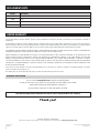
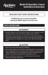
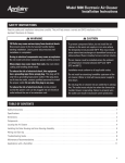
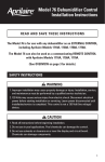
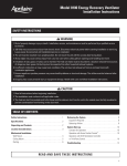
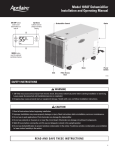
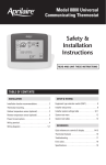
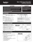
Model 850 Steam Humidifier Fan Pack
Model 850 Steam Humidifier Fan Pack
Installation & Maintenance Instructions
Table of Contents
Safety Cautions . . . . . . . . . . . . . . . . . . . . . . . . . . . . . . . . . . . . . . . . . . 2
Start-up Procedure . . . . . . . . . . . . . . . . . . . . . . . . . . . . . . . . . . . . . . . 7
Materials List . . . . . . . . . . . . . . . . . . . . . . . . . . . . . . . . . . . . . . . . . . . . 2
Maintenance . . . . . . . . . . . . . . . . . . . . . . . . . . . . . . . . . . . . . . . . . . . . 7
Operation . . . . . . . . . . . . . . . . . . . . . . . . . . . . . . . . . . . . . . . . . . . . . . . 3
Troubleshooting Guide . . . . . . . . . . . . . . . . . . . . . . . . . . . . . . . . . . . . 7
Specifications & Dimensions . . . . . . . . . . . . . . . . . . . . . . . . . . . . . . 3
Replacement Parts . . . . . . . . . . . . . . . . . . . . . . . . . . . . . . . . . . . . . . . 8
Installation Instructions
Limited Warranty . . . . . . . . . . . . . . . . . . . . . . . . . . . . . . . . . . . . . . . . . 8
Location . . . . . . . . . . . . . . . . . . . . . . . . . . . . . . . . . . . . . . . . . . . . . . . 3
Mount Housing . . . . . . . . . . . . . . . . . . . . . . . . . . . . . . . . . . . . . . . . . . 5
Hose Connections . . . . . . . . . . . . . . . . . . . . . . . . . . . . . . . . . . . . . . . . 5
Electrical Wiring . . . . . . . . . . . . . . . . . . . . . . . . . . . . . . . . . . . . . . . . . 6
Grille Installation . . . . . . . . . . . . . . . . . . . . . . . . . . . . . . . . . . . . . . . . 6
READ AND SAVE THESE INSTRUCTIONS
Safety CAUTIONS
CAUTION
Attention Installer
Read this manual before installing. This product must be installed by a qualified HVAC contractor and in compliance with local,
state, federal, and governing codes. Improper installation can cause property damage, severe personal injury, or death as a
result of electric shock, burns, or fire.
Read all cautions and instructions.
Read this manual before performing service or maintenance procedures on any part of the system. Failure to follow all cautions
and instructions could produce the hazardous situations described, resulting in property damage, personal injury, or death.
Failure to follow the instructions in this manual can cause moisture to accumulate, which can cause damage to structure and
furnishings.
Hot surfaces and hot water
This steam humidification system has extremely hot surfaces. Steam pipes, and dispersion chamber can be as hot as 212°F
(100°C). Discharged steam is not always visible. Contact with hot surfaces, discharged hot water, or air into which steam has
been discharged can cause severe personal injury. To avoid severe burns, follow procedures in this manual when performing
service or maintenance procedures on any part of the system.
Disconnect electrical power
Disconnect electrical power before installing supply wiring or performing service or maintenance procedures on any part of
the humidification system. Failure to disconnect electrical power could result in fire, electrical shock, and other hazardous
conditions. These hazardous conditions could cause property damage, personal injury, or death.
Contact with energized circuits can cause property damage, severe personal injury, or death as a result of electrical shock or
fire. Do not remove access panels until electrical power is disconnected.
Follow the shutdown procedure in this manual before performing service or maintenance procedures on any part of the system.
Electrical shock hazard
If the humidifier starts up responding to a call for humidity during maintenance, severe bodily injury or death from electrical shock
could occur. Follow the procedures in this manual before performing service or maintenance procedures on the humidifier system.
SHARP EDGES
Sharp edges may cause serious injury from cuts. Use care when cutting openings and handling housing and grille.
EXCESS HUMIDITY
Do not operate humidifier if blower is not operating. Do not place objects in front of steam discharge. Condensation may cause
damage.
MATERIALS LIST
Materials Furnished
Not Furnished
Model 850 Fan Pack
2 wire ties
Manual humidistat
2 grille mounting screws
Steam hose – 6’ steam hose provided with the Model 800
humidifier
4 housing mounting screws
Neoprene condensation tubing – 3/8” ID, 10’
Steam hose clamp – provided with the Model 800 humidifier
Wire for humidistat and wire to power Model 850 Fan Pack
2
Operation
On a call for humidity the Model 800 Residential Steam Humidifier provides power to the Model 850 Fan Pack. The Model 850 blower distributes
the steam to the room. When the call for humidity ends and the humidifier stops producing steam, the Model 850 Fan Pack will continue to
operate for 2 minutes to distribute the remaining steam before de-activating.
Specifications & Dimensions
Technical Specifications
Dimensions
• 24 VAC supplied by Model 800 humidifier
• Stainless steel steam dispersion chamber
Figure 1 – Dimensions of the Model 850
14
• Noise dampening housing liner
• Ultra quiet fan
5
4-3/4
17-1/16
7-13/16
Fan
Inlet
Steam Dispersion
Manifold
Fan Outlet
6-7/8
3/8
6-1/16
7-1/16
90-1554
INSTALLATION INSTRUCTIONS
location
The Model 850 must be located near the Model 800 Residential
Steam Humidifier to minimize the length of the steam hose. If the
Model 850 is mounted directly above the humidifier, 16” is required
for the steam hose to make the bend. See Figure 2. NOTE: The loop
in the condensate hose is required to prevent steam from escaping
into the drain.
Figure 2 – Side View
IMPORTANT:
Loop drain hose
below Model 850
to provide trap.
16" Minimum
for Steam Hose
30" Recommended
for Service Access
Drain
90-1551
3
INSTALLATION INSTRUCTIONS (continued)
location (continued)
Six feet of steam hose is provided with the Model 800 Steam
Humidifier. If the Fan Pack is mounted more than six feet from the
Humidifier, splice in 1” copper pipe as shown in Figure 3. Due to
condensation inside the hose or pipe, the output of the Fan Pack
depends on the length of the steam hose or pipe connecting it to the
Humidifier. When the humidifier is wired to 120 volts, the fan pack
will deliver 11.5 gpd with up to 2 feet of hose or insulated pipe. Each
additional 2 feet of hose or pipe will reduce output by approximately
1 gpd.
Humidity behaves like a gas and under ideal conditions will expand to
fill the space. However, air movement due to drafts or as a result of
temperature stratification may cause uneven distribution of humidity
within the conditioned space. To ensure even RH distribution, install
system in a central location. If a central location is not available, it
may be necessary to install two systems. Two systems will provide
more even RH distribution than one.
Figure 3
3/4" x 1"
Reducing Coupling
Fan
Pack
Steam Hose
1-1/2" Hose Clamp
1" Insulated Copper Pipe
1-1/2" Hose Clamp
Steam Hose
To prevent condensation on surfaces and furnishings, install the fan
pack so the steam being discharged has enough room to be absorbed
into the air before encountering surfaces.
Humidifier
The following guidelines are for a 120V installation in which the unit
discharges into a space with 70°F air temperature and 40% RH.
90-1565
• Allow 4 feet of unobstructed space directly in front of the grille.
• Allow 2 feet on either side of the grille.
Figure 4 – Minimum Clearances
• Allow 1-1/2 feet above the grille.
See Figure 4.
If the fan pack operates on 240V, allow an additional foot of space
between the grille and any obstruction or surface.
1-1/2 feet
minimum
to ceiling
2 feet
minimum to
side wall
If the room temperature is less that 70°F, allow an additional 6” to
each distance for every two degree drop in temperature.
If the RH set point is higher than 45%, allow an additional foot of
space between the grille and any obstruction or surface.
Warmer room air temperature and RH below 35% will reduce the
amount of unobstructed space required to absorb discharged steam,
but the distances provided are recommended minimums.
4 feet
minimum to
objects in
front of grille
Maximize
90-1552
4
INSTALLATION INSTRUCTIONS (continued)
Mount Housing
The Model 850 Fan Pack installs between the studs of a standard 16”
on-center wall. Drywall on both sides of the wall must be removed
for piping and wiring the Model 850. To ensure proper operation, the
Model 850 must be mounted level. Use the four 1-1/2” mounting
screws provided to attach the housing to the wall studs. See Figure 5.
Figure 5 – Wall Opening and Mounting
Wall Stud
Wall Cut-out
7-1/4"
14-1/4"
16"
Wall Studs on Center
90-1550
Hose Connections
Connect the steam hose (provided with the Model 800) to the
Model 850 and use hose clamp (provided with Model 800) to
secure. See Figure 6. If more than 6 feet is required, use insulated
hard pipe as shown in Figure 3. See Model 800 manual for the
affect on capacity.
Figure 6 – Hose Connections
Connect 3/8” ID condensate tubing to the Model 850 and use
wire-tie to secure See Figure 6. To create a trap, make a 6” loop
in the condensate hose. See Figure 2. NOTE: The 6” loop must be
located below the Model 850 connection. Do not kink condensate
hose and use wire tie to secure loop. The loop is required to
prevent steam from escaping into the drain.
Condensate
Tube
Steam
Tube
Electrical
Terminals
90-1560
5
INSTALLATION INSTRUCTIONS (continued)
Electrical Wiring
Mount the Manual Humidistat in the area to be humidified according to installation instructions included with control. Install the
humidistat in the same room or area as the Model 850 discharge, but at least ten feet away. Wire the Manual Humidistat to the Model 800
using standard 24 volt thermostat wire. See Figure 7.
Disconnect all power to Model 800 before wiring the Model 850 terminals to the Fan terminals on the Model 800. Use standard 24 volt
thermostat wire. See Figure 7.
Figure 7 – Wiring Diagram for Manual Humidistat and Model 850
Manual Humidistat
Mounting
Screw
FANPACK HUMIDISTAT
24 VAC
Terminals
Mounting
Screw
Model 850 Steam Humidifier Fan Pack
WIRE – 18 Awg Acceptable For 24 Vac Application.
Aprilaire Model 800
Steam Humidifier
90-1560
GrillE Installation
Use the two 5/8” screws to attach the Model 850 grille to the fan housing and drywall. See Figure 5. If painting the grille is desired, see a
painting professional for acceptable paint products for high temperature (212°F), high humidity environments.
6
Start-Up Procedure
Once the Model 800 Humidifier and Model 850 Fan Pack are installed, turn on main power to humidifier and open saddle valve. Turn on the
humidifier and turn humidistat up. Model 850 fan will turn on. Once canister fills and water boils, steam will flow from the manifold and the fan
will distribute it to the room. Set humidistat to desired RH.
CAUTION
The front of the Fan Pack will be hot. Steam may not always be visible.
Do not touch the front of the Fan Pack or place hand in front of the manifold.
Verify that there are no leaks at steam hose connections. Set humidistat for desired humidity level.
The Model 850 will operate on a call for humidity and the production of steam by the Model 800 Residential Steam Humidifier. When the call for
humidity is de-activated, the fan will continue to operate for 2 minutes to distribute the remaining steam in the steam hose.
Maintenance
After Replacing the Model 800 Humidifier Canister:
• Ensure fan is operating during a call for humidification.
• Check drain, steam and condensate hoses for kinks, blockages, leaks or cracks. Replace if necessary.
• Ensure steam outlet of the fan pack is not blocked.
TROUBLESHOOTING Guide
If a problem arises with the Aprilaire Model 850 Steam Humidifier Fan Pack, please review the following troubleshooting guide for possible
causes and solutions. If the problem persists, call Aprilaire Tech Support toll-free at 1-800-334-6011. Please be prepared to describe the exact
nature of the problem.
TABLE 1 – Troubleshooting Guide
Problem
Possible cause
Action
Water dripping from
Model 850
Tubing connection
Check all connections.
Fan not operating
See “Fan does not operate”.
Steam outlets blocked
Clean steam dispersion manifold outlet.
Foaming in canister or
steam hose
Rinse components with clean water.
Wiring
Check wiring.
Model 800 power
Check that Model 800 is powered and on.
No humidity call
Adjust humidistat setting. Check location of humidistat.
Circuit board output
Confirm 24 VAC output from Model 800 fan terminals during a call for humidity.
Motor failure
Replace fan motor.
Fan noise
Check for obstructions or damage to fan.
Fan does not operate
Noise
7
REPLACEMENT PARTS
Part No.
Description
4997
Condensate Tubing with Wire Ties
4998
Grille
4999
Fan
4655
Manual Humidistat
Limited Warranty
Your Research Products Corporation Aprilaire® fan pack is expressly warranted for five (5) years from date of installation to be free from defects in materials or
workmanship.
Research Products Corporation’s exclusive obligation under this warranty shall be to supply, without charge, a replacement for any part of the fan pack which is
found to be defective within such five (5) year period and which is returned not later than thirty (30) days after said five (5) year period by you to either your original
supplier or to Research Products Corporation, Madison, Wisconsin 53701, together with the model number and installation date of the fan pack.
THIS WARRANTY SHALL NOT OBLIGATE RESEARCH PRODUCTS CORPORATION FOR ANY LABOR COSTS AND SHALL NOT APPLY TO DEFECTS IN WORKMANSHIP
OR MATERIALS FURNISHED BY YOUR INSTALLER AS CONTRASTED TO DEFECTS IN THE FAN PACK ITSELF.
IMPLIED WARRANTIES OF MERCHANTABILITY OR FITNESS FOR A PARTICULAR PURPOSE SHALL BE LIMITED IN DURATION TO THE AFORESAID FIVE YEAR
PERIOD. RESEARCH PRODUCTS CORPORATION’S LIABILITY FOR INCIDENTAL OR CONSEQUENTIAL DAMAGES, OTHER THAN DAMAGES FOR PERSONAL
INJURIES, RESULTING FROM ANY BREACH OF THE AFORESAID IMPLIED WARRANTIES OR THE ABOVE LIMITED WARRANTY IS EXPRESSLY EXCLUDED.
THIS LIMITED WARRANTY IS VOID IF DEFECT(S) RESULT FROM FAILURE TO HAVE THIS UNIT INSTALLED BY A QUALIFIED HEATING AND AIR CONDITIONING
CONTRACTOR. IF THE LIMITED WARRANTY IS VOID DUE TO FAILURE TO USE A QUALIFIED CONTRACTOR, ALL DISCLAIMERS OF IMPLIED WARRANTIES SHALL
BE EFFECTIVE UPON INSTALLATION.
Some states do not allow limitations on how long an implied warranty lasts or the exclusion or limitation of incidental or consequential damages so the above
exclusion or limitations may not apply to you.
This warranty gives you specific legal rights and you may also have other rights which vary from state to state.
Warranty Registration
Visit us on-line at www.aprilaire.com to register your Aprilaire product.
If you do not have on-line access, please mail a postcard with your name, address, phone number,
model number of product purchased and date of installation to:
Research Products Corporation, P.O. BOX 1467, Madison, WI 53701
Your Warranty Registration information will not be sold or shared outside of this company.
Thank you!
RESEARCH PRODUCTS CORPORATION
P.O. Box 1467 • Madison, WI 53701-1467 • Phone: 608/257-8801 • Fax: 608/257-4357 • www.aprilairepartners.com
10008966 10.10
B2205158A
8
©2010 Research Products Corporation
Printed in U.S.A.