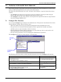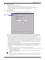
1
SITE MONITORING AND SERVICES
OPENCOMMS™ NFORM
USER MANUAL
Version 1.2
Release
TABLE OF CONTENTS
OPENCOMMS™ NFORM . . . . . . . . . . . . . . . . . . . . . . . . . . . . . . . . . . . . . . . . . . . . . . . . . . . . . . . .1
1.0
WHAT IS NFORM? . . . . . . . . . . . . . . . . . . . . . . . . . . . . . . . . . . . . . . . . . . . . . . . . . . . . . . .2
1.1
How Does Nform Work? . . . . . . . . . . . . . . . . . . . . . . . . . . . . . . . . . . . . . . . . . . . . . . . . . . . . . . . 2
1.2
What’s New in Version 1.2. . . . . . . . . . . . . . . . . . . . . . . . . . . . . . . . . . . . . . . . . . . . . . . . . . . . . 3
2.0
HOW DO YOU CONTACT LIEBERT FOR TECHNICAL SUPPORT? . . . . . . . . . . . . . . . . . . . . . . .4
3.0
WHO CAN BENEFIT FROM NFORM? . . . . . . . . . . . . . . . . . . . . . . . . . . . . . . . . . . . . . . . . . .5
3.1
Connections. . . . . . . . . . . . . . . . . . . . . . . . . . . . . . . . . . . . . . . . . . . . . . . . . . . . . . . . . . . . . . . . . 5
4.0
WHAT IS REQUIRED TO USE NFORM? . . . . . . . . . . . . . . . . . . . . . . . . . . . . . . . . . . . . . . . . .6
4.1
Connecting host computer and SNMP devices . . . . . . . . . . . . . . . . . . . . . . . . . . . . . . . . . . . . . 6
4.2
Requirements for Installing Nform . . . . . . . . . . . . . . . . . . . . . . . . . . . . . . . . . . . . . . . . . . . . . . 6
5.0
SAMPLE NFORM CONFIGURATION . . . . . . . . . . . . . . . . . . . . . . . . . . . . . . . . . . . . . . . . . . . .7
6.0
INSTALLING THE SOFTWARE . . . . . . . . . . . . . . . . . . . . . . . . . . . . . . . . . . . . . . . . . . . . . . . .8
6.1
Initial Installation . . . . . . . . . . . . . . . . . . . . . . . . . . . . . . . . . . . . . . . . . . . . . . . . . . . . . . . . . . . 8
6.2
Controlling Access to Configuration . . . . . . . . . . . . . . . . . . . . . . . . . . . . . . . . . . . . . . . . . . . . . 8
6.3
Upgrading to a Newer Version of Nform. . . . . . . . . . . . . . . . . . . . . . . . . . . . . . . . . . . . . . . . . . 9
7.0
OVERVIEW OF NFORM NET EVENT MANAGER . . . . . . . . . . . . . . . . . . . . . . . . . . . . . . . . . . 10
7.1
Configure Tab—Overview . . . . . . . . . . . . . . . . . . . . . . . . . . . . . . . . . . . . . . . . . . . . . . . . . . . . 10
7.1.1
7.2
Configure Menus and Toolbar Buttons . . . . . . . . . . . . . . . . . . . . . . . . . . . . . . . . . . . . . . . . . . . 11
Navigate Tab—Overview . . . . . . . . . . . . . . . . . . . . . . . . . . . . . . . . . . . . . . . . . . . . . . . . . . . . . 12
7.2.1
7.2.2
Navigate Menus and Toolbar Buttons. . . . . . . . . . . . . . . . . . . . . . . . . . . . . . . . . . . . . . . . . . . . 13
Informational Icons in the Navigation Tree . . . . . . . . . . . . . . . . . . . . . . . . . . . . . . . . . . . . . . . 14
7.3
Nform Features . . . . . . . . . . . . . . . . . . . . . . . . . . . . . . . . . . . . . . . . . . . . . . . . . . . . . . . . . . . . 15
8.0
GETTING STARTED WITH NFORM . . . . . . . . . . . . . . . . . . . . . . . . . . . . . . . . . . . . . . . . . . . 16
8.1
Start Nform. . . . . . . . . . . . . . . . . . . . . . . . . . . . . . . . . . . . . . . . . . . . . . . . . . . . . . . . . . . . . . . . 16
8.2
Connect to Server . . . . . . . . . . . . . . . . . . . . . . . . . . . . . . . . . . . . . . . . . . . . . . . . . . . . . . . . . . . 16
8.3
Log on as Administrator . . . . . . . . . . . . . . . . . . . . . . . . . . . . . . . . . . . . . . . . . . . . . . . . . . . . . 16
8.4
Change the Administrator Password . . . . . . . . . . . . . . . . . . . . . . . . . . . . . . . . . . . . . . . . . . . 17
8.5
Enter the Nform License Key . . . . . . . . . . . . . . . . . . . . . . . . . . . . . . . . . . . . . . . . . . . . . . . . . 18
8.6
Install the MultiLink Network Shutdown License (Optional). . . . . . . . . . . . . . . . . . . . . . . . 19
8.7
Set Up Security Settings . . . . . . . . . . . . . . . . . . . . . . . . . . . . . . . . . . . . . . . . . . . . . . . . . . . . . 20
i
9.0
CONFIGURING NFORM DEVICES . . . . . . . . . . . . . . . . . . . . . . . . . . . . . . . . . . . . . . . . . . . . 21
9.1
Add a Device . . . . . . . . . . . . . . . . . . . . . . . . . . . . . . . . . . . . . . . . . . . . . . . . . . . . . . . . . . . . . . . 21
9.2
Set Up the Device . . . . . . . . . . . . . . . . . . . . . . . . . . . . . . . . . . . . . . . . . . . . . . . . . . . . . . . . . . . 22
9.2.1
9.2.2
9.2.3
Device Setup tab . . . . . . . . . . . . . . . . . . . . . . . . . . . . . . . . . . . . . . . . . . . . . . . . . . . . . . . . . . . . . 22
Views tab. . . . . . . . . . . . . . . . . . . . . . . . . . . . . . . . . . . . . . . . . . . . . . . . . . . . . . . . . . . . . . . . . . . 23
Alarms tab. . . . . . . . . . . . . . . . . . . . . . . . . . . . . . . . . . . . . . . . . . . . . . . . . . . . . . . . . . . . . . . . . . 24
9.3
Add Devices to Navigation Tree . . . . . . . . . . . . . . . . . . . . . . . . . . . . . . . . . . . . . . . . . . . . . . . 25
9.4
Add Floor Plans to Show Device Location. . . . . . . . . . . . . . . . . . . . . . . . . . . . . . . . . . . . . . . . 26
9.5
Add Floor Plans to Navigation Tree . . . . . . . . . . . . . . . . . . . . . . . . . . . . . . . . . . . . . . . . . . . . 27
9.6
Services and Applications . . . . . . . . . . . . . . . . . . . . . . . . . . . . . . . . . . . . . . . . . . . . . . . . . . . . 28
9.6.1
9.6.2
9.6.3
9.6.4
Alarm Service - Configuration . . . . . . . . . . . . . . . . . . . . . . . . . . . . . . . . . . . . . . . . . . . . . . . . . .
Alarm Service - Event Alarms . . . . . . . . . . . . . . . . . . . . . . . . . . . . . . . . . . . . . . . . . . . . . . . . . .
Trap Service . . . . . . . . . . . . . . . . . . . . . . . . . . . . . . . . . . . . . . . . . . . . . . . . . . . . . . . . . . . . . . . .
SNMP Service . . . . . . . . . . . . . . . . . . . . . . . . . . . . . . . . . . . . . . . . . . . . . . . . . . . . . . . . . . . . . . .
28
29
30
31
10.0
CONFIGURING MULTILINK DEVICES . . . . . . . . . . . . . . . . . . . . . . . . . . . . . . . . . . . . . . . . . .32
10.1
Requirements to Use MultiLink Features . . . . . . . . . . . . . . . . . . . . . . . . . . . . . . . . . . . . . . . 32
10.2
Add a MultiLink Client . . . . . . . . . . . . . . . . . . . . . . . . . . . . . . . . . . . . . . . . . . . . . . . . . . . . . . 33
10.3
Set Up a MultiLink Notify Action . . . . . . . . . . . . . . . . . . . . . . . . . . . . . . . . . . . . . . . . . . . . . . 34
11.0
LOCAL AND SERVER NOTIFICATION CONFIGURATION . . . . . . . . . . . . . . . . . . . . . . . . . . . . . 35
11.1
Local Notification Policy . . . . . . . . . . . . . . . . . . . . . . . . . . . . . . . . . . . . . . . . . . . . . . . . . . . . . 35
11.2
Server Notifications . . . . . . . . . . . . . . . . . . . . . . . . . . . . . . . . . . . . . . . . . . . . . . . . . . . . . . . . . 36
11.2.1
11.2.2
11.2.3
11.2.4
11.3
Set Up an E-Mail Action . . . . . . . . . . . . . . . . . . . . . . . . . . . . . . . . . . . . . . . . . . . . . . . . . . . . . .
Set Up a File Write Action . . . . . . . . . . . . . . . . . . . . . . . . . . . . . . . . . . . . . . . . . . . . . . . . . . . . .
Set Up an External Program to Run . . . . . . . . . . . . . . . . . . . . . . . . . . . . . . . . . . . . . . . . . . . . .
Assign Actions to Alarms . . . . . . . . . . . . . . . . . . . . . . . . . . . . . . . . . . . . . . . . . . . . . . . . . . . . . .
37
38
39
40
Advanced Notification . . . . . . . . . . . . . . . . . . . . . . . . . . . . . . . . . . . . . . . . . . . . . . . . . . . . . . . 41
11.3.1 SNMP Get Request. . . . . . . . . . . . . . . . . . . . . . . . . . . . . . . . . . . . . . . . . . . . . . . . . . . . . . . . . . . 41
11.3.2 SNMP Set Request . . . . . . . . . . . . . . . . . . . . . . . . . . . . . . . . . . . . . . . . . . . . . . . . . . . . . . . . . . . 42
12.0
NFORM MONITORING—NAVIGATION TREE . . . . . . . . . . . . . . . . . . . . . . . . . . . . . . . . . . . . . 43
12.1
Viewing the Navigation Tree . . . . . . . . . . . . . . . . . . . . . . . . . . . . . . . . . . . . . . . . . . . . . . . . . . 43
12.1.1 Navigate View—HTML-Supported Devices . . . . . . . . . . . . . . . . . . . . . . . . . . . . . . . . . . . . . . . 43
12.1.2 Navigate View—Non-HTML Devices . . . . . . . . . . . . . . . . . . . . . . . . . . . . . . . . . . . . . . . . . . . . 43
12.2
Information Available for HTML-Supported Devices . . . . . . . . . . . . . . . . . . . . . . . . . . . . . . 44
12.2.1
12.2.2
12.2.3
12.2.4
12.2.5
12.3
HTML monitor tab . . . . . . . . . . . . . . . . . . . . . . . . . . . . . . . . . . . . . . . . . . . . . . . . . . . . . . . . . . .
HTML control tab (selected devices only) . . . . . . . . . . . . . . . . . . . . . . . . . . . . . . . . . . . . . . . . .
HTML configure tab (selected devices only) . . . . . . . . . . . . . . . . . . . . . . . . . . . . . . . . . . . . . . .
HTML event log tab (selected devices only) . . . . . . . . . . . . . . . . . . . . . . . . . . . . . . . . . . . . . . . .
HTML support tab . . . . . . . . . . . . . . . . . . . . . . . . . . . . . . . . . . . . . . . . . . . . . . . . . . . . . . . . . . .
44
45
46
47
48
Information Available for Non-HTML Devices. . . . . . . . . . . . . . . . . . . . . . . . . . . . . . . . . . . . 49
12.3.1
12.3.2
12.3.3
12.3.4
Query Device. . . . . . . . . . . . . . . . . . . . . . . . . . . . . . . . . . . . . . . . . . . . . . . . . . . . . . . . . . . . . . . .
Set Values . . . . . . . . . . . . . . . . . . . . . . . . . . . . . . . . . . . . . . . . . . . . . . . . . . . . . . . . . . . . . . . . . .
Download Device. . . . . . . . . . . . . . . . . . . . . . . . . . . . . . . . . . . . . . . . . . . . . . . . . . . . . . . . . . . . .
View Data Definition . . . . . . . . . . . . . . . . . . . . . . . . . . . . . . . . . . . . . . . . . . . . . . . . . . . . . . . . .
ii
49
50
51
52
13.0
MANAGING ALARMS . . . . . . . . . . . . . . . . . . . . . . . . . . . . . . . . . . . . . . . . . . . . . . . . . . . . . 53
13.1
View Alarms . . . . . . . . . . . . . . . . . . . . . . . . . . . . . . . . . . . . . . . . . . . . . . . . . . . . . . . . . . . . . . . 54
13.2
View Alarm Data Definition—SiteNet Integrator Only. . . . . . . . . . . . . . . . . . . . . . . . . . . . . 54
13.3
Silence the Default Beep . . . . . . . . . . . . . . . . . . . . . . . . . . . . . . . . . . . . . . . . . . . . . . . . . . . . . 55
13.4
Filtering Alarms by Type . . . . . . . . . . . . . . . . . . . . . . . . . . . . . . . . . . . . . . . . . . . . . . . . . . . . . 55
13.5
Change Alarm Status. . . . . . . . . . . . . . . . . . . . . . . . . . . . . . . . . . . . . . . . . . . . . . . . . . . . . . . . 55
13.5.1 Acknowledge an Alarm. . . . . . . . . . . . . . . . . . . . . . . . . . . . . . . . . . . . . . . . . . . . . . . . . . . . . . . . 55
13.5.2 Delete an Alarm . . . . . . . . . . . . . . . . . . . . . . . . . . . . . . . . . . . . . . . . . . . . . . . . . . . . . . . . . . . . . 55
13.6
Add or View Alarm Comments . . . . . . . . . . . . . . . . . . . . . . . . . . . . . . . . . . . . . . . . . . . . . . . . 56
13.6.1 Add Comments to an Alarm. . . . . . . . . . . . . . . . . . . . . . . . . . . . . . . . . . . . . . . . . . . . . . . . . . . . 56
13.6.2 View or Edit Comments . . . . . . . . . . . . . . . . . . . . . . . . . . . . . . . . . . . . . . . . . . . . . . . . . . . . . . . 56
13.6.3 Delete Comments . . . . . . . . . . . . . . . . . . . . . . . . . . . . . . . . . . . . . . . . . . . . . . . . . . . . . . . . . . . . 56
13.7
Change Colors Indicating Alarm Status . . . . . . . . . . . . . . . . . . . . . . . . . . . . . . . . . . . . . . . . . 57
14.0
RUNNING NFORM . . . . . . . . . . . . . . . . . . . . . . . . . . . . . . . . . . . . . . . . . . . . . . . . . . . . . . . 58
14.1
Starting or Stopping Nform Services . . . . . . . . . . . . . . . . . . . . . . . . . . . . . . . . . . . . . . . . . . . 58
15.0
UNINSTALLING NFORM / REMOVING LICENSE KEYS . . . . . . . . . . . . . . . . . . . . . . . . . . . . . . 59
15.1
Uninstalling Nform . . . . . . . . . . . . . . . . . . . . . . . . . . . . . . . . . . . . . . . . . . . . . . . . . . . . . . . . . 59
15.2
Deleting License Keys . . . . . . . . . . . . . . . . . . . . . . . . . . . . . . . . . . . . . . . . . . . . . . . . . . . . . . . 60
15.2.1 Deleting Secondary Nform License Keys . . . . . . . . . . . . . . . . . . . . . . . . . . . . . . . . . . . . . . . . . 60
15.2.2 Deleting the MultiLink Network Shutdown License . . . . . . . . . . . . . . . . . . . . . . . . . . . . . . . . 60
16.0
LIEBERT SOFTWARE PROGRAM LICENSE AGREEMENT. . . . . . . . . . . . . . . . . . . . . . . . . . . .61
APPENDIX A - TECHNICAL INFORMATION & FREQUENTLY ASKED QUESTIONS . . . . . . . . . . . . . . . . 63
APPENDIX B - DATA MONITORED BY NFORM . . . . . . . . . . . . . . . . . . . . . . . . . . . . . . . . . . . . . . . . 64
B.1
Sample Data Points and Alarms . . . . . . . . . . . . . . . . . . . . . . . . . . . . . . . . . . . . . . . . . . . . . . . 64
B.2
Sample Values From a UPS. . . . . . . . . . . . . . . . . . . . . . . . . . . . . . . . . . . . . . . . . . . . . . . . . . . 65
APPENDIX C - ORDERING PARTS FROM LIEBERT . . . . . . . . . . . . . . . . . . . . . . . . . . . . . . . . . . . . . 66
iii
FIGURES
Figure 1
Sample Nform configuration . . . . . . . . . . . . . . . . . . . . . . . . . . . . . . . . . . . . . . . . . . . . . . . . . . . . . . . 7
TABLES
Table 1
Table 2
Table 3
Table 4
Table 5
Table 6
Table 7
Table 8
Table 9
Table 10
Table 11
Table 12
Table 13
Table 14
Table 15
Table 16
New features in Nform Version 1.2 . . . . . . . . . . . . . . . . . . . . . . . . . . . . . . . . . . . . . . . . . . . . . . . . . . 3
Configure tab menu options - summary . . . . . . . . . . . . . . . . . . . . . . . . . . . . . . . . . . . . . . . . . . . . . 11
Navigate tab menu options - summary . . . . . . . . . . . . . . . . . . . . . . . . . . . . . . . . . . . . . . . . . . . . . . 13
Informational icons - summary . . . . . . . . . . . . . . . . . . . . . . . . . . . . . . . . . . . . . . . . . . . . . . . . . . . . 14
Features available in Nform. . . . . . . . . . . . . . . . . . . . . . . . . . . . . . . . . . . . . . . . . . . . . . . . . . . . . . . 15
Alarm service options . . . . . . . . . . . . . . . . . . . . . . . . . . . . . . . . . . . . . . . . . . . . . . . . . . . . . . . . . . . . 28
Event alarms . . . . . . . . . . . . . . . . . . . . . . . . . . . . . . . . . . . . . . . . . . . . . . . . . . . . . . . . . . . . . . . . . . . 29
SNMP service options . . . . . . . . . . . . . . . . . . . . . . . . . . . . . . . . . . . . . . . . . . . . . . . . . . . . . . . . . . . . 31
Fields for e-mail messages . . . . . . . . . . . . . . . . . . . . . . . . . . . . . . . . . . . . . . . . . . . . . . . . . . . . . . . . 37
Fields for file entry . . . . . . . . . . . . . . . . . . . . . . . . . . . . . . . . . . . . . . . . . . . . . . . . . . . . . . . . . . . . . . 38
Fields for arguments . . . . . . . . . . . . . . . . . . . . . . . . . . . . . . . . . . . . . . . . . . . . . . . . . . . . . . . . . . . . . 39
Options for viewing device event log . . . . . . . . . . . . . . . . . . . . . . . . . . . . . . . . . . . . . . . . . . . . . . . . 47
Sample data points and alarms - Environmental unit . . . . . . . . . . . . . . . . . . . . . . . . . . . . . . . . . . 64
Sample data points and alarms - UPS unit . . . . . . . . . . . . . . . . . . . . . . . . . . . . . . . . . . . . . . . . . . . 64
Sample device information available for monitoring - Example for a UPS . . . . . . . . . . . . . . . . . . 65
Nform Part Numbers . . . . . . . . . . . . . . . . . . . . . . . . . . . . . . . . . . . . . . . . . . . . . . . . . . . . . . . . . . . . 66
iv
OPENCOMMS™ NFORM
Version 1.2 Release
User Manual
Liebert® Corporation
Liebert Corporation
Liebert Europe
Liebert Asia
1050 Dearborn Drive
P.O. Box 29186
Columbus, Ohio 43229
Sales
Phone: 1 800 877 9222
FAX: 1 614 841 6022
Technical Support
Phone: 1 800 222 5877
FAX: 1 614 841 5471
E-mail: [email protected]
Via Leonardo Da Vinci 8
Zona Industriale Tognana
35028 Piove Di Sacco (PD)
Italy
Phone: 39 049 9719 111
FAX: 39 049 5841 257
7/F, Dah Sing Financial Centre
108 Gloucester Road, Wanchai
Hong Kong
Phone: 852 25722201
FAX: 852 28029250
Liebert Web Site: http://www.liebert.com
Nform Web Site: http://nform.liebert.com
SL-29000 (June 7, 2005)
1
What Is Nform?
1.0
WHAT IS NFORM?
Liebert developed Nform to use Simple Network Management Protocol (SNMP) to monitor and manage a wide variety of networked equipment, protecting it from costly damage resulting from power
failures and mechanical breakdowns. The monitored equipment can include industrial air conditioning units, Uninterruptible Power Supply (UPS) units and other devices that accommodate an SNMP
card to communicate over an Ethernet network. Nform will monitor and manage devices manufactured by Liebert or by other equipment makers.
Nform constantly monitors configured equipment, warns of problems ranging from power quality to
environmental conditions.
This product also permits configurable responses to equipment alarms, including support for audible
alarms, e-mail and on-screen notification.
1.1
How Does Nform Work?
Nform on a host computer communicates with up to 30 devices, by default, using SNMP to detect
problems ranging from power quality to environmental conditions.
The user has the option of expanding Nform’s network capabilities with additional licenses. Licenses
are available in increments of 30, 100 or 500 additional monitored and managed devices. Additional
concurrent user licenses are available for one, five or 10 additional users.
Nform employs the SNMP protocol and static IP addresses to issue notifications and warnings,
launch scripts and send e-mail messages. It uses HTML to graphically display system information for
devices with an SNMP card that is Web-enabled. Nform performs its monitoring and management
processes using the network—instead of requiring separate, expensive hardware and cables that
might run alongside network lines.
Typical sequence
• Nform constantly monitors multiple SNMP devices made by Liebert or other manufacturers.
• In the event any alarm occurs, Nform receives an SNMP trap.
• According to configuration, Nform issues a local notification to the monitoring computer, executes
any associated actions—sending e-mails, writing alarm data in files and launching scripts—and
logs alarm data.
• Users can later acknowledge and delete any alarms from Nform’s Net Event Manager.
2
What Is Nform?
1.2
What’s New in Version 1.2
Table 1 summarizes the new features available in Nform Version 1.2.
Table 1
New features in Nform Version 1.2
Feature
Improvement
Client Server
Architecture
Connects multiple Nform Clients to a single Nform Server. Operators can now manage the
Nform system from multiple workstations with concurrent client licenses.
Client
Enhancements
The Nform Client on the server can now load automatically when the server receives a new
alarm.
The following devices are now supported:
• Candeo IP
Expanded
Device
Support
• Candeo SP 24
• Candeo SP 48
• Candeo Access
• Alber Battery Monitoring BDS256
• Alber Battery Monitoring BDS40
•
•
•
•
•
•
•
Liebert NX
Liebert-Hiross HiNet
Emerson Actura DC
OpenComms TMNET
OpenComms TMPDUNET
Emerson Network Power iTrust UH11
Liebert RPMP
Standard
Report
Action
Enhancements
The standard report actions—File Write, Email and Run External Program—have two new
features that allow you to:
• Customize alarm output by specifying the content of the alarm message.
• Test the configured actions to verify they will operate correctly.
Support of
MultiLink 1.5
Clients
The system can now send shutdown commands to customer workstations or servers that
have the MultiLink 1.5 Client software installed.
• Nform can send shutdown commands to MultiLink clients after receiving an alarm.
• To activate this feature, you may use your existing MultiLink Network Shutdown License.
Customized View
for Each User
The Administrator and Power User logons can now be set up with different customized
navigation views.
Advanced
Notification
The system now supports two new notification actions, SNMP Get and SNMP Set requests.
• SNMP Get Request - Obtain a status report of any or all devices at the time of the alarm.
• SNMP Set Request - Automatically turn outputs, air conditioning and reboot outlets off or
on when an alarm is received.
Update Data
Definitions
All standard devices are now supported for data definitions, allowing users to get a detailed
description of each alarm and data point for a specific device.
3
How Do You Contact Liebert for Technical Support?
2.0
HOW DO YOU CONTACT LIEBERT FOR TECHNICAL SUPPORT?
For help on deciding how to set up Nform or any other Liebert monitoring product, contact Liebert’s
Software Technical Applications Support Center at:
UNITED STATES
Phone: 1 800 222 5877
FRANCE
Phone: +33 1 43600177
GERMANY
Phone: +49 89 9050070
ITALY
Phone: +39 049 9719111
NETHERLANDS
Phone: +31 33 2474074
UNITED KINGDOM
Phone: +44 1628403200
WORLDWIDE
Phone: 1 614 841 6755
FAX: 1 614 841 5471
All Products: http://www.liebert.com
Nform: http://nform.liebert.com
E-mail: [email protected]
4
Who Can Benefit From Nform?
3.0
WHO CAN BENEFIT FROM NFORM?
Any industry operating devices utilizing the SNMP protocol can benefit from using Nform to protect
valuable equipment, data and other assets in the event of power or mechanical failure.
Nform’s protection can be extended beyond equipment manufactured by Liebert to encompass other
makers’ SNMP devices. Nform ships with templates—specifications and functionality—for Liebertbuilt SNMP devices. Liebert offers templates for other manufacturers’ equipment; contact your local
Liebert representative, value-added reseller, or distributor for information.
3.1
Connections
Nform works with a network connection and either of these types of SNMP cards:
1. SNMP card with Web capability such as the OpenComms NIC, OpenComms™ Web Card
2. SNMP card without Web capability, such as the Intellislot™ SNMP card
Nform can monitor a network that includes any combination of LANs, WANs and any other type of
network.
5
What is Required to Use Nform?
4.0
WHAT IS REQUIRED TO USE NFORM?
Visit the Liebert Web site at http://nform.liebert.com for the latest product information. The Web site
always has the most detailed and up-to-date information on system requirements and Nform’s capabilities.
4.1
Connecting host computer and SNMP devices
SNMP communications allow you to take full advantage of Nform’s features. The host computer connects to an SNMP-enabled device over a network. Information and management commands may be
passed over the Internet, a Local Area Network (LAN) or a Wide Area Network (WAN) via SNMP protocol and static IP addresses.
4.2
Requirements for Installing Nform
Before beginning installation, review these requirements:
The prospective user must have:
• The Nform software (Visit the Liebert Web site at http://nform.liebert.com or contact your local Liebert representative, value-added reseller, or distributor for information.)
• This manual (downloadable from the Liebert Web site)
• A computer with Microsoft® Windows® NT, 2000, XP or 2003 Server
• A communications link between the SNMP device and the host computer: local network, Internet
or Intranet, utilizing SNMP protocol and static IP addresses
• Availability of IP Port 162 for receiving traps
• TCP/IP connectivity throughout the network
NOTE
Check with your System Administrator about the need to disable certain
network or virus protection software.
6
Sample Nform Configuration
5.0
SAMPLE NFORM CONFIGURATION
Nform is installed on a single workstation and can be configured to monitor and manage up to 30
SNMP devices by default. The user has the option of expanding Nform’s network capabilities with
additional licenses. Licenses are available in increments of 30, 100 or 500 additional monitored and
managed devices. The primary license key allows one local user; licenses are available to add one, five
or 10 concurrent users. See Table 16 for details on additional device/user licenses.
Nform is designed to monitor any part of a network. Its functionality permits it to monitor any SNMPenabled device that can be contacted via local network or the Internet. These devices include those
made by Liebert and, with templates available from Liebert, units built by other manufacturers.
Nform may be configured to turn devices on or off as needed—for example, turning on a fan—and to
obtain a snapshot of the status of any or all devices when an alarm is received. These functions
require an Advanced Notification License for SNMP get/set request actions (see Table 16).
Nform can also interface with computers that have MultiLink 1.5 installed, sending shutdown notices
as needed when alarms are received. This capability requires a MultiLink Network Shutdown
License (see Table 16).
Nform-Enterprise includes licenses for the Advanced Notification and MultiLink shutdown features.
Example of Nform on a Network
Figure 1 shows one possible configuration of an Nform server that is monitoring and managing various devices—UPS, environmental and monitoring units. The network also has Nform client software
installed on another computer, several computers with MultiLink 1.5 installed and a network management system.
When an alarm is received, Nform can send e-mail notifications, append alarm data to a file and run
scripts. With appropriate licenses, Nform can also send shutdown notifications to the computers with
MultiLink 1.5 installed, obtain a snapshot of the status of connected devices and turn devices on or off
when an alarm is received.
Figure 1
Sample Nform configuration
Network
Management
System
OpenComms
Nform
client
OpenComms Nform
server
MultiLink
1.5
client
MultiLink
1.5
client
MultiLink
1.5
client
Ethernet
UPS
Battery
monitoring
unit
Monitoring
unit
7
UPS
DC
unit
Environmental
unit
Installing the Software
6.0
INSTALLING THE SOFTWARE
This section explains how to install OpenComms Nform.
• For a first-time installation, follow the instructions in 6.1 - Initial Installation.
• If you are upgrading to a newer version of Nform and want to keep configuration settings, proceed
to 6.3 - Upgrading to a Newer Version of Nform.
6.1
Initial Installation
• Insert the OpenComms Nform CD in the CD drive. The Installation Wizard starts automatically.
If the Installation Wizard does not open automatically, launch the file Setup.exe from the CD.
One way to do this is: Click on the Start button, and then on Run. In the Run window, click on
Browse to locate the file Setup.exe on the CD, highlight the file name and click Open. Click OK
to begin installation.
• After viewing the Welcome screen and clicking Next, read the Nform License agreement.
• If you accept the terms and conditions of the license agreement, click on the I accept the
license agreement radio button and then click on the Next button.
• If you do not accept the terms and conditions, click on the I do not accept the license
agreement radio button and then click on Cancel to abort the installation.
• In the User Information window, enter your full user name and click on one of the following two
buttons to choose whether other users of this computer will have access to the Nform application:
• Anyone who uses this computer
• Only for me (user name)
• The Destination Folder window, shown below left, displays the location where the software will be
installed. Liebert recommends using the default location. (To select a different location, click on
the Browse button and choose the location.) Click on the Next button.
Destination Folder window
Select Installation Type window
Install Nform’s
Client features
(default)
Install both
Client & Server
features
• In the Select Installation Type window, shown above right, choose whether to install Nform’s Client features (the default—recommended for most users) or Client / Server features, which is
recommended for Nform Server. Click on the Next button.
• In the Ready to Install the Application window, click Next to begin installing the software. A dialog box displays the progress of the installation process, which may take a few minutes.
• A message indicates that installation was successful. Click Finish to exit the installation process.
6.2
Controlling Access to Configuration
To protect configuration settings from unauthorized users, Nform is set up for two classes of users:
• Administrator—full access, including configuration capability
• Power User—can view and respond to alarms; no access to configuration
Initially both types of user have a default password, liebert (all lowercase). Liebert recommends
changing the Administrator password, as described in 8.4 - Change the Administrator Password,
to limit access to configuration settings.
You may set up a customized view of devices for each user (see 9.3 - Add Devices to Navigation Tree).
8
Installing the Software
6.3
Upgrading to a Newer Version of Nform
When upgrading to a newer version, the user does not need to remove the existing installation. During the upgrade, Nform preserves all configuration files—for example, configured devices, floor plans,
actions.
To install the Nform software upgrade, follow the steps below (for complete details, see 6.1 - Initial
Installation):
• Launch the installation file Setup.exe from the CD.
• If you accept the terms and conditions of the Nform license agreement, click on the I accept the
license agreement radio button and then click on the Next button.
• Choose whether other computer users will have access to the Nform application:
• Anyone who uses this computer
• Only for me (user name)
• The Destination Folder window, shown below, displays the location where the software will be
installed. Click Next.
For upgrades, you must use the same directory path as the previous installation of
Nform to keep your configuration settings.
For upgrades, use the
same directory path as
previous installation
to keep configuration
settings
• In the Select Installation Type window, choose whether to install Nform’s Client features (the
default—recommended for most users) or Client / Server features (recommended for Nform
Server. Click Next.
• Follow the prompts to complete the installation.
The next time you start Nform, all previous configuration settings should be in place.
9
Overview of Nform Net Event Manager
7.0
OVERVIEW OF NFORM NET EVENT MANAGER
This section provides a quick look at the features available with various SNMP devices and the functions accessible through Nform’s tabs, menus and toolbar buttons.
The Nform Net Event Manager’s two tabs—Navigate and Configure—logically divide Nform’s functionality.
• The Navigate tab displays the operational status and condition of monitored and managed
devices. This tab becomes more important after Nform is fully set up.
• The Configure tab is the entry point for all setup functions required for Nform to begin monitoring and managing SNMP devices.
7.1
Configure Tab—Overview
Access to the Configure tab is limited to the Administrator. This prevents unauthorized users from
altering Nform’s settings. This tab allows you to:
•
•
•
•
Enter the Nform license key(s) and install the MultiLink Network Shutdown License
Set up devices to be monitored and managed by Nform, organized in virtually any fashion
Add floor plans as visual reminders of device locations
Specify actions for Nform to take in response to an alarm from any device: send e-mails, add
alarm information to a file and launch scripts
• Set up security precautions, such as changing the Administrator’s password
The Configure tab, with its various options, is shown below.
Configure
tab
Configuration
options
The following table shows where to find detailed information about key Configure tab functions.
Function
For a detailed description, see:
• Change passwords
• Enter Nform licenses
• Install MultiLink Network Shutdown License*
8.0 - Getting Started With Nform
• Add SNMP devices and floor plans to navigation tree
9.0 - Configuring Nform Devices
• Set up MultiLink 1.5 clients for shutdown notifications*
10.0 - Configuring MultiLink
Devices
• Set up Nform’s response to alarms (send e-mail, write to file, run script)
• Link responses to alarms for specific devices
• Configure SNMP get/set requests*
11.0 - Local and Server Notification
Configuration
* Requires additional license (included with Nform-Enterprise version); see Table 16
10
Overview of Nform Net Event Manager
7.1.1
Configure Menus and Toolbar Buttons
When the Configure tab is selected, Nform displays three menus at the top of the window: File,
Edit, and Help. Each menu has a drop-down list of options, which appear only when applicable. For
example, the Save option appears in the File menu only when a change needs to be saved.
The Toolbar buttons, which appear directly below the menu, offer alternatives for selected menu
options, as shown below. Buttons appear on the Toolbar only when their function is applicable. To display helpful text describing a button’s function, hold the mouse over the button. Clicking on the View
menu and choosing Show Text Labels causes labels to appear under the buttons.
Configure Menus
Toolbar
Table 2 shows the menu options available in the Configure tab and where to learn more about each.
Table 2
Menu
File
Configure tab menu options - summary
Option
Toolbar
button
New
Create a new device, floor plan, action
or other item
Save
Save changes to configured items
Exit
—
For more information, see:
—
8.0 - Getting Started With Nform
Quit the Nform application
—
Cancel
Abort changes that have not been saved
—
Delete
Delete a device, floor plan, action
or other item
—
Check Nform version
—
Edit
Help
Function
About
—
11
Overview of Nform Net Event Manager
7.2
Navigate Tab—Overview
The main features of the Navigate tab are:
• Viewing summary status, alarm history, and parametric data for any device in the navigation tree
• Tracking alarms in an event log and in user-specified files
• Responding to alarms
Access to the Navigate tab is unlimited; it can be viewed by the Administrator or the Power User
group. This permits any authorized user to view the status of monitored, managed devices and
respond to alarms.
The Navigate tab view varies, depending on the type of SNMP card installed in a device. A device
equipped with a Web-enabled SNMP card may be viewed with a Web browser. For devices with an
SNMP card that does not support HTML, Nform displays the data in tabular format.
For devices equipped with Web-enabled SNMP cards, the Navigate tab may be used to change configuration settings, test a UPS battery and alter other settings.
These functions are performed through the Control and Configure tabs of the SNMP card’s Web display. These HTML tabs may be accessed by any user who has the SNMP card’s password. This means
that an Nform Power User with the SNMP card password would be able to alter some device settings
through the HTML interface.
The Navigate window has two parts. The left side displays all configured devices as a navigation tree,
and the right side shows information about any selected item in the tree.
Navigate
tab
Information
for selected
device
Navigation
tree
SAMPLE DATA:
DEVICE WITH
WEB INTERFACE
SAMPLE DATA:
DEVICE WITHOUT
WEB INTERFACE
The table below shows where to find detailed information about the Navigate tab’s functions.
Function
For a detailed description, see:
View the status of all devices
12.0 - Nform Monitoring—Navigation Tree
Manage Nform’s alarm log: acknowledge and delete alarms
13.0 - Managing Alarms
Also visit these Liebert Web sites for more information on getting your equipment monitored:
• OpenComms Web card: http://www.liebert.com/dynamic/displayproduct.asp?id=1018&cycles=60Hz
• OpenComms NIC card:
http://www.liebert.com/dynamic/displayproduct.asp?id=998&cycles=60Hz
12
Overview of Nform Net Event Manager
7.2.1
Navigate Menus and Toolbar Buttons
When the Navigate tab is selected, Nform displays up to four menus at the top of the window: File,
View, Alarms, and Help. Each menu has a drop-down list of options. Menus and options appear only
when applicable. For example, the Alarms menu is available only when alarms are displayed.
The Toolbar buttons, which appear directly below the menu, offer alternatives for selected menu
options, as shown below. Buttons appear on the Toolbar only when their function is applicable. To display helpful text describing a button’s function, hold the mouse over the button. Clicking on the View
menu and choosing Show Text Labels causes labels to appear under the buttons.
Navigate Menus
Toolbar
Table 3 shows the menu options available in the Navigate tab and where to learn more about each.
Table 3
Navigate tab menu options - summary
Menu
File
View
(Navigate
tab only)
Option
Help
Function
For more information, see:
Log On
—
(Before logging in) Log on as
Administrator / Power User
Lock Application
—
Secure Nform from unauthorized
use
Exit
—
Quit the Nform application
—
Show Text Labels
—
Display text below Toolbar buttons
—
Go To > Back
For Web pages:
• Return to previous page
—
Go To > Forward
For Web pages:
• Move to next page
—
Go To > Home
For Web pages:
• Go to Home page
http://www.liebert.com
—
Stop
For Web pages:
• Stop loading page
—
Refresh
For Web pages:
• Update device data
—
8.3 - Log on as Administrator
—
Change color for alarm status
(active, acknowledged, closed)
13.7 - Change Colors
Indicating Alarm Status
Silence
Silence an alarm
13.3 - Silence the Default
Beep
Acknowledge
Change active alarm status to
acknowledged
13.5.1 - Acknowledge an
Alarm
Comments
Add comments to an alarm
13.6 - Add or View Alarm
Comments
Delete
Remove a closed alarm from
alarms listing
13.5.2 - Delete an Alarm
Options
Events
(Navigate
tab with
alarms
displayed)
Toolbar
button
About
—
—
Check Nform version
13
—
Overview of Nform Net Event Manager
7.2.2
Informational Icons in the Navigation Tree
The navigation tree’s informational icons change to indicate normal operation, active alarms, communications loss and other conditions of SNMP devices.
Icon denotes
device with active
alarm
Icon denotes loss
of communication
with device
Table 4 summarizes the meaning of icons Nform employs to indicate the status of monitored and
managed SNMP devices.
Table 4
Informational icons - summary
Status
Normal
operation
Toolbar
button
Meaning
For more information
Floor plan and all components in
normal status
—
SNMP device in normal status
—
Event history - shows listing of
active and acknowledged alarms
13.0 - Managing Alarms
Problem in a
component device
Floor plan with at least one
component device in alarm or
communication loss status
13.0 - Managing Alarms
Active
alarm
Device in active alarm status
13.0 - Managing Alarms
Communication
loss
No communication with device
See Note below
NOTE
When Nform displays this icon
, verify that your network cables are connected.
If further action is required, consult your SNMP card user manual.
14
Overview of Nform Net Event Manager
7.3
Nform Features
Table 5 lists the features available in Nform.
Table 5
Features available in Nform
Feature
System
Features
OpenComms Nform 1.2
Centralized Event Logging
Yes
Multi-User
Yes
Authenticated Access
Yes
Auto Logoff (Enhanced Security)
Yes
SiteScan Web Interface
Yes
MultiLink Interface
Yes
Windows NT 4.0 w/SP6 or higher, Windows 2000,
Windows XP, Windows 2003 Server
Supported Operating Systems
License Packages
Device
Management
Notifications
Alarm
Management
Available in 30, 100 & 500 node increments
Floorplans
Yes
Customized System Topologies
Yes
Broad Device Support
Yes
Web Card Integration
Yes
Configurable SNMP Device Views
Yes
SNMP Device Configuration
Yes
UPS Equipment Support
All UPS, Environmental, Power Distribution and
Monitoring products that support an SNMP interface
Air Equipment Support
All UPS, Environmental, Power Distribution and
Monitoring products that support an SNMP interface
Power Equipment Support
All UPS, Environmental, Power Distribution and
Monitoring products that support an SNMP interface
DC Equipment Support
All UPS, Environmental, Power Distribution and
Monitoring products that support an SNMP interface
Open Architecture (Monitoring of
non-proprietary SNMP devices)
Yes
Device Status Polling
Yes
Real Time Monitoring
Yes
E-Mail Notification
Yes
Run External Program Capability
Yes
File Write
Yes
Play Sound Wave
Yes
Play Default Beep
Yes
Flash Application When Minimized
Yes
Propagate Application to Foreground
Yes
Remote Monitoring
Yes
Shutdown
Yes
SNMP Set Request(s)
Yes
SNMP Get Request(s) Report
Yes
Acknowledge Alarms
Yes
Comments to Alarm
Yes
Alarm Filtering by Device
Yes
Time Zone Independent
Yes
Alarm Helpful Text
Yes
15
Getting Started With Nform
8.0
GETTING STARTED WITH NFORM
After installing the software, you should change the default password for security purposes and enter
the license key so you can begin configuring devices for monitoring.
NOTE
The Nform ports and standard SNMP ports may have to be open for the firewall; otherwise,
Nform might not function properly.
Saving Configuration Changes
Some changes to Nform’s configuration are saved automatically; others will need to be saved before
they take effect. If these buttons
appear on the toolbar and are illuminated (not grayed-out),
you must save changes in one of the following ways:
• Click on the File menu at the top of the window, and then click on Save.
or
• Click on the Save button
on the toolbar.
or
• Right-click in the lower right side of the window, then click on Save in the popup menu.
8.1
Start Nform
To start the application:
• Click on the Start button, then on Programs, then on OpenComms Nform (program folder),
and finally on OpenComms Nform (application icon).
8.2
Connect to Server
The Server Link Status window opens, as shown at right,
allowing you to specify the server you wish to connect to.
• The Server IP box displays the IP address of a server
where Nform was installed. To connect to a different
server, enter the IP address or domain name in the
Server IP box.
• To make the server connection automatic each time
you start Nform, click to place a check mark (✔) in the
Automatically connect to the server check box.
The next time you start Nform, this window will not
appear. This option is recommended if there is only
one server you will want Nform to connect to. You may
change this option later (see 9.6.1 - Alarm Service Configuration).
• Click on the Connect button to connect to the server listed in the Server IP box. (Or click Exit to
cancel.)
8.3
Log on as Administrator
After connecting to the server, Nform opens and displays a
blank screen, as shown at right. This remains until the
user logs on as either Administrator or Power User.
The Administrator user name permits full access for configuring the software.
To log on as Administrator:
• Click on the File menu at the top of the window, then
click on Log On.
• In the Login window, choose Administrator (the
default) in the User Name box.
• In the Password box, enter the default password,
liebert (all lowercase letters).
• Click on the OK button.
16
Getting Started With Nform
8.4
Change the Administrator Password
The software has two users, Administrator and Power User. The Administrator has full access to configuration and monitoring; the Power User has viewing privileges only. These user names cannot be
changed.
The default password for both users is liebert (all lowercase letters). Liebert recommends changing
the password for the Administrator for security purposes. The password is case-sensitive and may
consist of up to eight characters—any combination of letters, numbers or symbols.
To change the Administrator password:
• Log on as Administrator.
• Click on the Configure tab.
• In the left side of the window, click on Local Users and Groups, and then on Users.
• In the right side of the window, double-click on Administrator to open the Change Password
box.
• Enter the new password in the Password box. The password is case-sensitive and may be up to
eight characters long (any combination of letters, numbers and other characters).
• Confirm the new password by re-entering it in the Verify Password box.
• Click OK.
Follow the same procedure if you wish to change the Power User password. You must be logged on as
Administrator to change this password.
You may set up different views in the Navigate tab for each user. See 9.3 - Add Devices to Navigation Tree for details.
17
Getting Started With Nform
8.5
Enter the Nform License Key
You must install the Nform license key from the sticker on the CD case before configuring Nform to
manage and monitor devices and inform users of conditions affecting SNMP devices.
• If you purchased the Nform-Enterprise pre-bundled package, the primary license key allows for
five concurrent users and 100 devices to be monitored. The Enterprise package also includes an
Advanced Notification License and a MultiLink Network Shutdown License.
• If you purchased the Nform software separately (the non-Enterprise version), the primary
license key allows for one workstation (local user) and 30 devices to be monitored.
Additional license keys are available from Liebert to add concurrent users (1, 5 or 10), devices (30,
100 or 500) or the Advanced Notification SNMP Get/Set Request features. Contact your local Liebert representative or see Appendix C - Ordering Parts From Liebert for information.
Each additional license must be installed separately, as described in this section.
To install an Nform license key:
• Log on as Administrator.
• Click on the Configure tab.
New
button
• In the left side of the window, double-click on License Key Administration, then click on
OpenComms Nform License Keys.
• Click on the File menu at the top of the window, then click on New. (Or click the New button
on the toolbar.) This opens the Liebert License Utility window. Click Next.
• Read the license agreement, and place a check mark in the box to accept the terms. Click Next.
• Enter the 24-character license key from the sticker on the CD case or the certificate provided by
Liebert, then click on Submit.
License Key Information
After installation, the license key number
appears in the right side of the window. If you
have installed more than one license key, the
primary license key appears first in the list.
• Double-click on the license key number in
the right side of the window to open an
information window, as shown at right.
• This window displays important details
about your license, including the license
agreement, accessible by clicking on the
Issuer Statement button.
Your primary license key cannot be deleted, but
you may wish to remove a secondary license
key—for example, to move it to another computer to monitor a different group of devices.
See 15.2.1 - Deleting Secondary Nform
License Keys for details.
18
License key
appears here
Getting Started With Nform
8.6
Install the MultiLink Network Shutdown License (Optional)
If you purchased the MultiLink Network Shutdown License—either separately or as part of the
Nform-Enterprise pre-bundled package—two steps are needed to activate the MultiLink shutdown
features:
• First, install the MultiLink Network Shutdown License as described in this section.
• Then configure MultiLink devices as described in 10.0 - Configuring MultiLink Devices.
NOTE
The Nform Enterprise CD contains the MultiLink Unlimited License:
cdDrive:\MultiLink\MLLKU\MLLKU.LICENSE
The MultiLink Network Shutdown License is available from Liebert. For more information, contact
your local Liebert representative or see Appendix C - Ordering Parts From Liebert.
To install the MultiLink Network Shutdown License:
• Log on as Administrator.
• Click on the Configure tab.
New
button
Browse
button
• In the left side of the window, double-click on License Key Administration, then click on
MultiLink Network Shutdown License.
• Click on the File menu at the top of the window, then click on New. (Or click the New button
on the toolbar.) This opens the MultiLink License Install window. Click Next.
• Enter the full path and file name of the MultiLink Network Shutdown License provided by
Liebert, or click the Browse button to locate the file. Then click on Install.
NOTE
Due to the design of the license, only one MultiLink Network Shutdown License can be added
to a system.
License Key Information
After installation, the MultiLink Network
Shutdown License appears in the right side of
the window.
• Double-click on the MultiLink Network
Shutdown License in the right side of the
window to open an information window, as
shown at right.
• This window displays important details
about your license, including the license
agreement, accessible by clicking on the
Issuer Statement button.
To remove this license, see 15.2.2 - Deleting
the MultiLink Network Shutdown
License.
19
Getting Started With Nform
8.7
Set Up Security Settings
As a security precaution, you may enable a feature that locks the Nform application after a specified
amount of idle time following the Administrator logon. When this occurs, the application remains
locked until the user enters a password. This feature is intended to prevent unauthorized personnel
from using the Administrator’s workstation to alter Nform settings.
By default, this feature is disabled (False) with an idle time of 25 minutes.
Even when this feature is enabled, Nform will not log off the Administrator user when the Configure
tab is active.
To enable this security option:
• Log on as Administrator.
• Click on the Configure tab.
• In the left side of the window, click on Security Settings, then on Local Policies, and finally on
Security Options. The right side of the window displays two options.
Enable (or Disable) Automatic Logoff
• Double-click on Automatically log off user when logon time expires to open the Security
Options window, shown above right.
• To enable the automatic logoff feature, select True from the drop-down list and click OK. (To disable the feature, select False. With this option, no automatic logoff will occur.)
• Click on the File menu at the top of the window, then click on Save. (Or click the Save button
on the toolbar.)
Change Amount of Idle Time Before Automatic Logoff
• To change the amount of idle time that must
elapse before the Administrator is logged off,
double-click on Amount of idle time
required before log off in minutes to open
the Security Options window, shown at right.
• Enter the desired idle time in minutes and
click OK.
• Click on the File menu at the top of the window, and then click on Save. (Or click the
Save button
on the toolbar.)
20
Configuring Nform Devices
9.0
CONFIGURING NFORM DEVICES
This section describes how to configure devices that will be monitored, add floor plans as visual aids,
set up the navigation tree and view or change settings for alarm, trap and SNMP services.
9.1
Add a Device
To add a device:
• Log on as Administrator and click on the Configure tab.
• In the left side of the window, click on Device Manager, then on SNMP Devices.
• Click on the File menu at the top of the window, then click on New. (Or click the New button
on the toolbar.) This opens the Add SNMP Device window, as shown below.
Categories of
supported devices
Enter a
descriptive
name
Device’s
IP address
Check box if
device has a
Web-enabled
card installed
• Name: Choose a descriptive name for the device—for example, Nfinity-1 1st Floor Computer
Room. This name will appear in the navigation tree that displays monitored devices.
• IP Address: Enter the device’s IP address, available from the System Administrator.
• HTML Supported: If the device has an SNMP card that supports a Web interface, place a check
mark in this box. This feature allows you to view SNMP queries via a Web browser.
• Device Type: Click on the appropriate button—Air, UPS, Power or Other—to display a list of
supported devices, and then click on the name of the device from the displayed list.
• Click Create. This opens the SNMP Devices window, as shown in 9.2 - Set Up the Device.
21
Configuring Nform Devices
9.2
Set Up the Device
The SNMP Devices window has three tabs:
• The Device Setup tab allow you to enter a community string and timeout value.
• The Views tab lets you determine which informational items appear in the Navigate tab.
• The Alarms tab allows you to set up alarms and corresponding actions.
9.2.1
Device Setup tab
The window opens with the Device Setup tab selected, as shown below.
Device Setup
tab
Shaded boxes do not require entry; they simply display information—name, IP address, HTML support—entered when the device was added, as described in the previous section, 9.1 - Add a Device.
• By default, the HTTP port is 80. If desired, enter a different number in the HTTP box.
• Enter a community string in the Community box. The community string entered in this box must
match the community string entered in the SNMP card. The community string is case-sensitive.
• The Community Set box can be used to configure the community string for a device that has a secondary IP address and community string configured for Read-Write or Set access. In most cases,
the value configured in the Community Set box will be the same as the value in the Community
box, which is the Read-Only setting.
• The Timeout box designates the number of seconds for a device to respond to an SNMP query. The
default value is 1 second; Liebert suggests this value is appropriate in most cases. (If you receive
an excessive number of timeout error messages, you might consider increasing the time.)
• Click OK.
• A message window asks if you want to add this device to the navigation tree.
• Click Yes if you wish to add the device to the navigation tree now. Then proceed to 9.3 - Add
Devices to Navigation Tree.
• To continue configuring this device, click the Views tab and proceed to 9.2.2 - Views tab, or
click No to add another device.
NOTE
If you are configuring several SNMP devices, it may be more convenient to wait until the last
device is configured before adding them to the navigation tree. Click No for all devices except
the last one.
22
Configuring Nform Devices
9.2.2
Views tab
The Views tab displays the types of data that can be retrieved from an SNMP device and displayed in the
Navigate tab as the Filtered View—for example, the type of device, model number and device status.
Liebert supplies a template for each SNMP device, containing data points applicable to that device.
(See Appendix B - Data Monitored by Nform for examples.)
For non-HTML devices, you may select items to be displayed in the Navigate tab. You may also
change the name of any item in the list to better suit your operation. Doing so will not change the
function of the item, but merely the descriptive text.
NOTE
The Views tab permits the user to select data to be displayed for non-HTML devices in the
Navigate tab.
All HTML devices will present the Web page to the user. Changes made in this window will not
affect the data displayed by the Web page.
To select an item or change its name:
• Log on as Administrator and click on the Configure tab.
• In the left side of the window, click on Device Manager, then on SNMP Devices.
• In the right side of the window, double-click on the name of a device.
• In the SNMP Devices window, click on the Views tab, as shown below.
Views tab
Check mark
indicates
item selected
for viewing
Click on item
name, then
press Enter
to change
name
• A check mark (✔) appears to the left of each item selected for viewing. Click in the check box to
remove a check mark; click again to place a check mark in the box.
• To change the name of an item, click on the name—for example, upsBatteryVoltage—and then
press the Enter key. The selected text will be highlighted and editable. (As an alternative, you
may make the text editable with a standard Windows renaming method: click on an item, wait a
short time and click on the item again.)
• Type the new name—for example, Voltage—and press the Enter key.
• To continue configuring this device, click the Alarms tab and proceed to 9.2.3 - Alarms tab, or
click OK to return to the Configure tab. If this device has not been added to the navigation tree,
a message window asks whether you want to do so.
NOTE
If you are configuring several SNMP devices, it may be more convenient to wait until the last
device is configured before adding them to the navigation tree.
23
Configuring Nform Devices
9.2.3
Alarms tab
The Alarms tab allows you to link actions, such as sending an e-mail, to specific alarms—this is
described later in 11.2.4 - Assign Actions to Alarms.
Liebert supplies a template for each SNMP device, containing the types of alarms applicable to that
device. (See Appendix B - Data Monitored by Nform for examples.)
You may also change the name of an alarm to better mesh with your system or procedures. This does
not change the function of the item, but merely the descriptive text. To do this:
•
•
•
•
Log on as Administrator and click on the Configure tab.
In the left side of the window, click on Device Manager, then on SNMP Devices.
In the right side of the window, double-click on the name of a device.
In the SNMP Devices window, click on the Alarms tab, as shown below.
Alarms tab
Click on item
and press enter
• Click on an item—for example, upsAlarmOutputOverload—and then press the Enter key. The
selected text will be highlighted and editable.
(An alternative way to make the text editable is with a standard Windows renaming method: click
on an item, wait a short time and click on the item again.)
• Type the new name—for example, OutputOverload—and press the Enter key.
• Click OK to return to the Configure tab.
• If this device has not been added to the navigation tree, a message window asks whether you
want to do so.
• Click Yes if you wish to add the device to the navigation tree now. Then proceed to 9.3 - Add
Devices to Navigation Tree.
• Click No if you want to add another device.
NOTE
If you are configuring several SNMP devices, it may be more convenient to wait until the last
device is configured before adding them to the navigation tree. Click No for all devices except
the last one.
24
Configuring Nform Devices
9.3
Add Devices to Navigation Tree
The Navigation tree window allows you to designate which managed devices will be monitored and
appear on the Navigate tab. You may set up different views for the Administrator and Power User.
This window opens if you clicked Yes in the final step described in 9.2.1 - Device Setup tab.
Another way to open this window is:
• Log on as Administrator and click on the Configure tab.
• In the left side of the window, click on Domain Management
• In the right side of the window, double-click on Local Domain, then on Site Navigation
Builder.
• Click on Administrator View to set up the view for the Administrator (or click on Power User
View to set up devices for a Power User).
All new devices appear in the Unmonitored Managed Devices portion in the lower right corner.
Left Arrow
key
New device
to be moved
To add a device to the tree:
• Use drag-and-drop:
• Click on a device and drag it to the Monitored Managed Devices pane.
• Release the mouse button when the location where the device belongs is highlighted. If no
location is highlighted, the device will be placed under the highest level in the tree—OpenComms Nform Alarm Logging in the example above.
or
• Use the arrow keys in the center of the window:
• In the Monitored Managed Devices pane at left, choose a location in the tree where the device
belongs—for example, OpenComms Nform Alarm Logging.
• Then select the device in the Unmonitored Managed Devices pane at right.
• Click on the Left Arrow key in the center of the window.
Only one device may be moved at a time.
Devices may be moved back to the Unmonitored Managed Devices pane by using drag-and-drop or
highlighting a device and then clicking on the Right Arrow key in the center of the window.
• Click OK to save changes and return to the Configure tab. (To close the window without saving
any changes, click on Cancel.)
25
Configuring Nform Devices
9.4
Add Floor Plans to Show Device Location
Floor plans may be added to Nform’s navigation tree as visual reminders
of where devices are located, as in the example shown at right.
Users may design these floor plans or contact Liebert for custom-built
plans. Floor plans must be in HTML format and placed in the Floorplans
folder as described in this section.
To make floor plans accessible to Nform client workstations, install the
floor plans either on a shared network drive or on each client workstation.
NOTE
Floor plans cannot display device status. These graphics are intended merely to display HTML
pages that may contain hyperlinks to Web devices or other Web pages.
To add a floor plan:
• Create a floor plan in HTML format.
• Copy the floor plan—the HTML file and any associated graphic files—into the Floorplans folder,
which is in the Data folder within the Nform application folder.
For example, if the Nform application is located on the C drive, the full path would be
C:\Program Files\Nform\Data\Floorplans.
•
•
•
•
•
NOTE
For multi-user systems, the floorplans directory should be manually copied to every client. For
security purposes, the system will not automatically update the clients.
Log on as Administrator and click on the Configure tab.
In the left side of the window, click on Domain Management
In the right side of the window, double-click on Local Domain and then on Floorplans.
Click on the File menu at the top of the window, then click on New.
(Instead, you may click on the New button
on the toolbar.)
This opens the Floorplans window, as shown below.
Enter a
descriptive
name
Select the
HTML file
• In the Name box, enter a descriptive name for the floor plan—for example, First Floor Computer
Room or Third Floor Finance.
• Select the HTML file from the Graphics drop-down list. A preview appears in the window.
• Click OK. The descriptive name appears in the right pane.
26
Configuring Nform Devices
9.5
Add Floor Plans to Navigation Tree
After adding floor plans to Nform, you must also place them in the navigation tree. Managed devices
can be placed under the appropriate floor plan to help the System Administrator pinpoint SNMP
devices for troubleshooting.
• In the left side of the window, click on Domain Management
• In the right side of the window, double-click on Local Domain, then on Site Navigation
Builder, and finally on Administrator View to set up the view for the Administrator (or click
on Power User View to set up devices for a Power User).
• This opens the Site Navigation Builder window, as shown below right. All floor plans that have
not been moved to the navigation tree appear in the Floorplans portion in the upper right corner.
Left Arrow
key
New plan to be moved
(highlight & drag to Monitored
Managed Devices at left—or
click on Left Arrow)
To move a floor plan to the navigation tree:
• Use drag-and-drop:
• Drag the floor plan to the Monitored Managed Devices pane.
• Release the mouse button when the location where the device belongs is highlighted. If no
location is highlighted, the floor plan will be placed under the highest level in the tree—OpenComms Nform Alarm Logging in the example above.
or
• Use the arrow keys in the center of the window:
• In the Monitored Managed Devices pane at left, choose a location in the tree where the floor
plan belongs—for example, OpenComms Nform Alarm Logging.
• Then select the floor plan in the Unmonitored Managed Devices pane at right.
• Click on the Left Arrow key in the center of the window.
Only one floor plan may be moved at a time.
Plans may be moved back to the Floorplans pane by using drag-and-drop or by highlighting a floor
plan and then clicking on the Right Arrow key in the center of the window.
• To associate a device with a floor plan, click on the device and drag it to the floor plan.
In the example above, a PowerSure is in the Third Floor Finance department. The other device in
the example—GXT 2U—is not associated with any floor plan.
• Click OK to save changes and return to the Configure tab. (To close the window without saving
any changes, click on Cancel.)
27
Configuring Nform Devices
9.6
Services and Applications
9.6.1
Alarm Service - Configuration
Nform has seven alarm service options that may be configured, as shown in Table 6. Liebert recommends keeping the default values for Options 1, 2 and 3.
Table 6
Alarm service options
Option
Default
Notes
1. Alarm service IP address
Server where
Nform was installed
Enter the IP address of the workstation where alarms are
reported.
2. TCP port used for client
connection
Port where
Nform was installed
Enter the number of the port used to connect the SNMP
device and the workstation specified in Option 1.
3. Location of data
Nform\Data where
Nform was installed
Specifies where to store Nform data—for example, floor
plans, device definitions and logs.
4. Maximum number of
records for alarm service
500
When the maximum is reached, a new record is added at the
(up to 5,000 allowed) beginning of the log; the oldest record is deleted from the end.
5. Automatically connect to
server when client loads
False
Change to True (automatically connect) if you want to
connect to the same server each time you start Nform.
6. Load the Nform client when
a new alarm is received
False
Change to True (load on alarm) for the Nform application to
start automatically whenever an alarm is received.
False
Change to True (auto-archive) to save deleted alarm
records in a file called Events.naf—records will be archived
as they are deleted from the log when the maximum is
reached (see Option 4 above).
7. Automatically Archive
Deleted Alarms
To view or change any option:
• Log on as Administrator and click on the Configure tab.
• In the left side of the window, click on Domain Management.
• In the right side of the window, double-click on Local Domain, Services and Applications,
Alarm Service and finally Configuration to display the options.
• To change the setting for an option:
• Double-click on any option to open the Alarm Service window for that option. The example
above shows the Automatically connect to server when client loads option.
• Enter the appropriate change and click OK.
• Click on the File menu at the top of the window, and then click on Save.
(Instead, you may click on the Save button
on the toolbar.)
• A message window advises that the change may not take effect until after the computer is
restarted. Click OK.
28
Configuring Nform Devices
9.6.2
Alarm Service - Event Alarms
The Alarm Service has event alarms, listed in Table 7, that you may map to any configured action—
for example, an e-mail action or a file write action.
Table 7
Event alarms
Event alarm
Description
Comm Check Successful
For use by Liebert Global Services to check Nform’s alarm processing
Managed Device Not Responding
These event alarms are recorded only when SNMP Agent Polling is
enabled (see 9.6.4 - SNMP Service).
Each represents a result when a managed device is polled.
Managed Device Return to Normal
Managed Device Alarms Present
To view or change the event assignments for any event alarm:
• Log on as Administrator and click on the Configure tab.
When the
selected
action is
executed
Check mark
assigns action
to event alarm
• In the left side of the window, click on Domain Management.
• In the right side of the window, double-click on Local Domain, Services and Applications,
Alarm Service and finally Event Alarms to display the alarm descriptions.
• Double-click on any event alarm to open the Event Assignments window, which displays all
actions that have been created.
• To link an action to the selected alarm, click to place a check mark to the left of the Action Name.
• By default, selected actions are executed both when an alarm is received and when it is cleared.
To change this setting, highlight an action and choose a setting in the Execute Type box:
• Both (default) - Action is executed both when an alarm condition occurs and when it is cleared.
• Active Only - Action is executed only when an alarm condition occurs.
• Cleared Only - Action is executed only when an alarm condition is cleared.
• When all actions are configured, click OK in the Event Assignments window.
• Configured actions appear in the Mapped
Actions column, as shown at right. The first
character signifies the type of action:
@ designates an E-Mail action
| designates a File Write action
> designates a Run External Program action
(Some actions may be hidden from view because of space restrictions. They can be revealed by
double-clicking on an alarm to open the Event Assignments window.)
• Click on the File menu at the top of the window, and then click on Save. (Instead, you may click
on the Save button
on the toolbar.) Click OK.
29
Configuring Nform Devices
9.6.3
Trap Service
The Trap Service is responsible for receiving and processing alarm notifications, or traps, from managed devices. Diagnostic features in this service can be used to troubleshoot network communication
problems between OpenComms Nform and SNMP devices.
The trap service has two options:
• The trap port—by default, this is 162.
• A diagnostic testing mode—by default, this feature is disabled.
Note: Use the diagnostic mode with caution. Diagnostic testing mode should be enabled only at
the request of a Liebert application support or field engineer. When enabled, this feature records
all received traps in a file called snmp.txt. This file is not managed and therefore can become very
large and cause the computer to crash.
Liebert recommends keeping the default values for these options.
To view or change either option:
• Log on as Administrator.
• Click on the Configure tab.
• In the left side of the window, click on Domain Management.
• In the right side of the window, double-click on Local Domain, Services and Applications,
Trap Service and finally Configuration to display the options.
• To change the setting for an option:
• Double-click on any option to open the Trap Service window for that option. The example
above shows the Turn on diagnostic testing for Trap service option.
• Enter the appropriate change and click OK.
• Click on the File menu at the top of the window, and then click on Save.
(Instead, you may click on the Save button
on the toolbar.)
• A message window advises that the change may not take effect until after the computer is
restarted. Click OK.
30
Configuring Nform Devices
9.6.4
SNMP Service
Nform has SNMP Service features for polling devices and testing Nform’s handling of traps, as listed
in Table 8.
• SNMP Agent Polling allows you to set up Nform to poll devices for their status at a specified
interval. By default, this feature is disabled (False) with a time interval of 1 minute.
When this feature is enabled, the icons in the Navigate tab indicate the status of each device
(see 7.2.2 - Informational Icons in the Navigation Tree): if any alarms are present, the status
is normal or the polled agent is not responding. (If there is no communication with a device, its
icon in the Navigate tab bears a large red X
—when Nform displays this icon, verify that your
network cables are connected. If further action is required, consult the SNMP card user manual.)
• SNMP Comm Check allows you to verify that Nform is correctly receiving and processing traps.
By default, this feature is disabled (False), starting each day at 800 (8:00 a.m, military time).
When this is enabled, Nform sends an SNMP Comm Check Trap to the SNMP Trap Service.
Table 8
SNMP service options
Option
Default
SNMP Agent Polling
SNMP Agent Polling Interval*
False
1 minute
* RECOMMENDED SETTINGS
for SNMP Agent Polling Interval
(based on number of devices)
SNMP Comm Check
False
SNMP Comm Check
Execute Time
800
(8 a.m.)
Notes
Change to True to activate device status polling at regular intervals.
Enter a time interval (number of minutes) between pollings.
First 30
devices:
5 minutes
(increase by 1 minute for each additional 30 devices)
First 500
devices:
15 minutes
(increase by 15 minutes for each additional 500 devices)
Change to True to send a test trap to the SNMP Trap Service.
In military time (24-hour clock format), enter the time to send test traps
each day—e.g., 800 for 8 a.m., 1400 for 2 p.m., 2330 for 11:30 p.m.
To view or change any option:
• Log on as Administrator and click on the Configure tab.
• In the left side of the window, click on Domain Management.
• In the right side of the window, double-click on Local Domain, Services and Applications,
SNMP Service and finally Configuration to display the options.
• To change the setting for an option:
• Double-click on any option to open the Configuration window for that option. The example
above shows the SNMP Agent Polling option.
• Enter the appropriate change and click OK.
• Click on the File menu at the top of the window, and then click on Save.
(Or click the Save button
on the toolbar.)
• A message window advises that the change will not take effect until after the service is
restarted. Click OK.
31
Configuring MultiLink Devices
10.0 CONFIGURING MULTILINK DEVICES
This section describes how to configure MultiLink 1.5 clients to receive shutdown notifications from
Nform.
10.1
Requirements to Use MultiLink Features
There are three requirements to use this feature:
1. A MultiLink Network Shutdown License
The MultiLink Network Shutdown License must be installed before configuration. For detailed
instructions, see 8.6 - Install the MultiLink Network Shutdown License (Optional).
For information on obtaining a MultiLink Network Shutdown License, see Table 16.
2. Liebert MultiLink 1.5 Software
You must install MultiLink 1.5 on each client computer you wish to use with Nform. The
MultiLink 1.5 software is provided on the Nform CD.
You may also download it free from the Liebert Web site (http://multilink.liebert.com). Visit
the Web site or contact your local Liebert representative, value-added reseller or distributor for
information.
3. The MultiLink 1.5 User Manual
You will need to refer to the MultiLink 1.5 user manual for important details on connecting and
configuring MultiLink devices.
The user manual is downloadable from the Liebert Web site (http://multilink.liebert.com).
Setting up MultiLink clients in Nform entails two steps:
• Adding each MultiLink 1.5 client to Nform
(see 10.2 - Add a MultiLink Client)
• Configuring Nform to send notification traps (see 10.3 - Set Up a MultiLink Notify Action)
to selected clients when an alarm is received
32
Configuring MultiLink Devices
10.2
Add a MultiLink Client
Before adding and setting up MultiLink clients for notifications, the MultiLink Network Shutdown
License must be installed in the OpenComms Nform system and MultiLink 1.5 Client software must
be installed on all workstations and servers that require orderly shutdown, as described in 10.1 Requirements to Use MultiLink Features.
The next step is to add each workstation running MultiLink 1.5 Client software to the Nform system.
To add a device:
•
•
•
•
Log on as Administrator and click on the Configure tab.
In the left side of the window, click on Device Manager.
In the right side of the window, double-click on MultiLink Shutdown Clients.
Click on the File menu at the top of the window, then click on New. (Or click the New button
on the toolbar.) This opens the MultiLink Shutdown Client window, shown below right.
Enter a
descriptive
name
Enter IP address
or domain name
• The Device Type box displays MultiLink Basic Notification Source. This cannot be changed.
• In the Device Name box, enter a descriptive name for the client computer.
• In the Hostname or IP Address, enter the client computer’s IP address or hostname, available
from the System Administrator.
• The default SNMP Community String is LiebertEM (case-sensitive).
• The SNMP Trap Listen Port designates the port used for communicating events (traps). The two
options available in the drop-down list are:
• 3029 (Private InterNic-assigned trap port)—the default setting
• 162 (Standard SNMP Trap port)
• The SNMP Send Request Port displays the port corresponding to the listen port selected:
SNMP Trap Listen Port
SNMP Send Request Port
MultiLink
3029
3027
Standard SNMP Protocol
162
161
• If desired, enter text in the Description box to help identify the device.
• Click OK. This saves the MultiLink Client device information.
• Continue adding MultiLink 1.5 Client workstations, then proceed to 10.3 - Set Up a MultiLink
Notify Action.
33
Configuring MultiLink Devices
10.3
Set Up a MultiLink Notify Action
After adding MultiLink 1.5 client computers to Nform, you may configure Nform to send notification
traps to selected clients when an alarm is received. Three types of traps may be sent:
• Warning Shutdown (On Battery)
• Critical Shutdown (Low Battery)
• Cancel Shutdown (Return to Normal)
To set up a MultiLink Notify action:
• Log on as Administrator and click on the Configure tab.
• In the left side of the window, click on Local and Server Notifications.
• In the right side of the window, double-click on Server Notifications, then on Shutdown
MultiLink Clients.
• In the File menu, click on New. (Or click the New button
on the toolbar.) This opens the
MultiLink Notify Action Setup window, shown below right.
Right Arrow
key
Clients
selected for
notification
All MultiLink
clients
• In the Description box, enter a descriptive name for the action—for example, Rack Sensor - High
Temperature.
• Click on one of the three Shutdown Notification radio buttons to choose the type of notification:
• Warning Shutdown (On Battery) - when an alarm is received, Nform sends a Warning
Shutdown message to selected target client computers. The MultiLink client then starts a
shutdown timer as configured by the user—typically several minutes.
• Critical Shutdown (Low Battery) - when an alarm is received, Nform sends a Critical
Shutdown message to selected target client computers. The MultiLink client then starts a
shutdown timer as configured by the user—typically 30 seconds.
• Cancel Shutdown (Return to Normal) - when an alarm is received, Nform sends a Cancel
Shutdown message to selected target client computers. The MultiLink client then cancels the
shutdown timer.
NOTE
Nform simulates the three SNMP UPS traps supported by MultiLink 1.5: On Battery,
Low Battery and Return to Normal. The simulated SNMP trap sent by Nform triggers the
client computer to initiate a shutdown or cancel a shutdown of the computer itself.
• All available MultiLink client computers appear in the MultiLink 1.5 Clients box in the left side
of the window. These devices were added as described in 10.2 - Add a MultiLink Client.
To designate a client to receive notifications, you must move it to the Selected Clients for Shutdown Notification box in the right side of the window. To do this:
• Click on a client name in the MultiLink 1.5 Clients box at left.
• Click on the Right Arrow key in the center of the window.
Only one device may be moved at a time. To remove a client from the selection, simply click on the
name and click on the Left Arrow key in the center of the window.
• Click OK. This saves changes to the MultiLink Notify Action.
34
Local and Server Notification Configuration
11.0 LOCAL AND SERVER NOTIFICATION CONFIGURATION
This section describes how to configure Nform to alert administrators and users when alarms are
received. It also details how to set up Nform to respond to alarms with certain actions, such as sending e-mails, recording event history and running an external program to protect data or equipment.
11.1
Local Notification Policy
The Local Notification Policy options allow you to determine the type of visual and audio notifications
Nform employs when an alarm is received.
When an alarm is received, you may choose:
•
•
•
•
To bring the Nform application to the foreground
To flash the minimized Nform icon in the taskbar
To play a sound from a WAV file once
To play a continuous beep
By default, these options are disabled (false).
To make changes:
• Log on as Administrator and click on the Configure tab.
• In the left side of the window, click on Local and Server Notifications.
• In the right side of the window, double-click on Local Notification Policy. The right side of the
window displays options for notification when an alarm is received.
• To change an option, double-click on the option in the right side of the window.
Select True
to activate
an option
Browse
to locate
sound
wave file
• To enable an option, as shown in the example above left, select True from the drop-down list and
click OK.
• If you enable a sound wave notification, you must also specify the location of the file in the window shown above right. To do this, enter the full path or click on the browse button to locate the
file, then click OK.
• Click on the File menu at the top of the window, and then click on Save.
(Instead, you may click on the Save button
on the toolbar.)
35
Local and Server Notification Configuration
11.2
Server Notifications
Certain Nform features may be set up to protect valuable equipment, data and other assets by
responding automatically to alarms in SNMP devices affected by such events as power failures, overheating and mechanical failures.
For example, if a cooling unit’s performance becomes impaired, Nform may be set up to send e-mail
alerts to various personnel, record data pertaining to the event and append it to a particular file and
launch a command or batch file that can execute user-customized scripts.
Set Up Actions
The first step in the process entails setting up the standard actions (e-mail, file write and command),
described in the next three sections:
• 11.2.1 - Set Up an E-Mail Action - send customized e-mail messages to selected recipients
• 11.2.2 - Set Up a File Write Action - record alarm information in a file
• 11.2.3 - Set Up an External Program to Run - launch a script when an alarm is received
Tie Actions to Alarms
The next step is to link each action to a particular event for a managed device. Actions must be created individually, but multiple actions may be attached to an event in one operation. Further, one
action may be attached to multiple events.
For instructions on linking actions to alarms, see:
• 11.2.4 - Assign Actions to Alarms
Advanced Notification
If you purchased the Advanced Notification License to enable SNMP Get Request and Set Request
functions, you will need to configure actions to collect data and control devices, as described in:
• 11.3 - Advanced Notification
36
Local and Server Notification Configuration
11.2.1 Set Up an E-Mail Action
To set up an e-mail:
•
•
•
•
Log on as Administrator and click on the Configure tab.
In the left side of the window, click on Local and Server Notifications.
In the right side of the window, double-click on Server Notifications, then on Email Actions.
In the File menu, click on New. (Or click the New button
on the toolbar.) This opens the
Email Actions window, shown below right.
• In the Description box, enter a descriptive name for the action—for example, UPS On Battery.
This name will appear later in a list of actions that can be assigned to events.
• In the SMTP Server box, enter the name of the outgoing mail server that this computer uses for
outgoing e-mail—mail.company.com.
• The Port box displays the standard SMTP port of 25. Enter a different port number if needed.
• In the To box, enter the e-mail address of the intended recipient—[email protected].
• In the From box, enter the e-mail address where replies should be sent—[email protected].
• In the Subject box, enter a subject for the e-mail—Store 112 Nfinity is On Battery.
• In the Body box, you may create a customized message for recipients. The message may consist of
text as well as fields from the drop-down list below the Body box, which are listed in Table 9.
Table 9
Fields for e-mail messages
Field
$REC_UTC$
$ADDRESS$
$DEV_NAME$
$EVENT_MESSAGE$
$EVENT_OID$
Description
The time when the alarm was received
The IP address of the device that sent the alarm
The user-defined name of the device that sent the alarm
The alarm message—for example, High Temperature, Low Temperature or On-Battery
The SNMP object-Identifier number
For example, if you enter:
An alarm in $DEV_NAME$ has been detected.
the e-mail message might read:
An alarm in GXT 2U 2nd Floor Computer Room has been detected.
• Click the Execute Test button to send a test e-mail message. Verify that the message was
received correctly.
• Click OK. This saves changes to the Email Action.
37
Local and Server Notification Configuration
11.2.2 Set Up a File Write Action
To set up a File Write Action:
•
•
•
•
Log on as Administrator and click on the Configure tab.
In the left side of the window, click on Local and Server Notifications.
In the right side of the window, double-click on Server Notifications, then on File Write Actions.
In the File menu, click on New. (Or click the New button
on the toolbar.) This opens the File
Write Actions window, as shown below right.
Browse to
locate file
• In the Description box, enter a name for the action—in the example above, NewFile. This name
will appear later in a list of actions that can be assigned to events.
• In the File Name box, enter the full path of the file where Nform will record details of events or
use the Browse button to locate the file. (To open a browse window, you may double-click in the
File Name box.) If the file does not exist, Nform will create it.
• Placing a check mark in the Append box will add data at the end of the file, preventing existing
data from being overwritten by new information.
If the Append box is not checked, the file will be replaced with each new alarm.
• In the text box below the Append check box, you may enter text to be written in the file when an
alarm is received. In addition to text, you may choose fields from the drop-down list below the text
box, which are listed in Table 10.
Table 10 Fields for file entry
Field
$REC_UTC$
Description
The time when the alarm was received
$ADDRESS$
The IP address of the device that sent the alarm
$DEV_NAME$
The user-defined name of the device that sent the alarm
$EVENT_MESSAGE$
The alarm message—for example, High Temperature, Low Temperature or On-Battery
$EVENT_OID$
The SNMP object-Identifier number
For example, if you enter:
Alarm detected in $DEV_NAME$
the file entry might read:
Alarm detected in GXT 2U 2nd Floor Computer Room
• Click the Execute Test button to test the File Write action. Verify that the file was created and
the text entered correctly.
• Click OK. This saves changes to the File Write Action.
38
Local and Server Notification Configuration
11.2.3 Set Up an External Program to Run
To set up an external program to run:
• Log on as Administrator and click on the Configure tab.
• In the left side of the window, click on Local and Server Notifications.
• In the right side of the window, double-click on Server Notifications, then on Run External
Program.
• In the File menu, click on New. (Or click the New button
on the toolbar.) This opens the Run
External Program Action window, as shown below right.
Browse to
locate
program
to run
• In the Description box, enter a descriptive name for the program to be run. This name will appear
later in a list of actions that can be assigned to events.
• In the Run box, enter the full path of the program Nform will initiate—either type the full path or
use the Browse button to locate the file. (To open a browse window, either click on the Browse
button or double-click in the Run box.)
• In the Arguments box, you may choose fields from the drop-down list below the Arguments box,
which are listed in Table 11. Selected fields will be appended to the Run command line.
Table 11
Fields for arguments
Field
$REC_UTC$
Description
The time when the alarm was received
$ADDRESS$
The IP address of the device that sent the alarm
$DEV_NAME$
The user-defined name of the device that sent the alarm
$EVENT_MESSAGE$
The alarm message—for example, High Temperature, Low Temperature or On-Battery
$EVENT_OID$
The SNMP object-Identifier number
• Click the Execute Test button to test the Run action. Verify that the action was performed correctly.
• Click OK. This saves changes to the Run External Program action.
39
Local and Server Notification Configuration
11.2.4 Assign Actions to Alarms
After an action is created, it must be assigned to an alarm for a managed device before it becomes
operative. An action—for example, sending e-mail notifications—may be assigned to more than one
alarm. Nform permits configuring actions separately for each alarm on each managed device. Each
action may be set up to be performed at particular stages of an alarm condition: when it occurs, when
it is cleared or both (default).
To assign an action to an alarm:
• Log on as Administrator and click on the Configure tab, then on Device Manager.
• In the right side of the window, double-click on SNMP Devices, then double-click on the SNMP
device that will be the object of the action.
• Click on the Alarms tab in the SNMP Devices window.
• Double-click on the alarm being set up to prompt a particular action. This opens the Event
Assignments window, shown below right, which displays all actions that have been created.
SNMP device
to become
object of
action
Alarm chosen
to trigger an
action
When
selected
action is
executed
Check mark
assigns action
to alarm
• To link an action to the selected alarm, click to place a check mark to the left of the Action Name.
• By default, selected actions are executed both when an alarm is received and when it is cleared.
To change this setting, highlight an action and choose a setting in the Execute Type box:
• Both (default) - Action is executed both when an alarm condition occurs and when it is cleared.
• Active Only - Action is executed only when an alarm condition occurs.
• Cleared Only - Action is executed only when an alarm condition is cleared.
• When all actions are configured, click OK in the Event Assignments window.
• The SNMP Devices window displays these
configured actions in the Assigned Events
column, as shown at right. The first character signifies the type of action:
@ designates an E-Mail action
| designates a File Write action
> designates a Run External Program action
(Some actions may be hidden from view because of space restrictions. They can be revealed by
double-clicking on an alarm to open the Event Assignments window.)
• Click OK in the SNMP Devices window to return to the Configure tab.
40
Local and Server Notification Configuration
11.3
Advanced Notification
The Get Request feature allows Nform to collect data on the status of connected devices at the time of
an event, such as an alarm, and store the data in a file for later review. With Set Request, Nform can
control devices based on an event—for example, turn on a fan when a high temperature is detected.
This section describes how to use these features, which require an additional Nform license key (see
Table 16 for details). The license key must be installed (see 8.5 - Enter the Nform License Key).
11.3.1 SNMP Get Request
To set up an SNMP request to get status information:
• Log on as Administrator and click on the Configure tab.
• In the left side of the window, double-click on Local and Server Notifications, then on
Advanced Notification and finally on SNMP Get Request.
• In the File menu, click on New. (Or click the New button
on the toolbar.) This opens the
SNMP Request Setup window, shown below right.
Click on an item
in the Data Points
box . . .
. . . and drag to
the Selected
Data Points
box
• In the Description box, enter a descriptive name for the action—for example, GXT 2U Status.
• In the File Name box, enter the full path and name of the file where the status data should be
stored—for example, C:\gxt2uStatus.txt.
• The Append box is checked by default, so that new data will be added at the end of the file
rather than overwrite the contents. To change this, click to remove the check mark.
• The Delimiter box has a comma (,) by default, indicating that data points will be delimited by
commas in the file. To change this, enter a different character in the box.
• Choose a device from the Managed Devices drop-down list. All available data for the selected
device appears in the Data Points box.
• Choose items you want the Data Points box using click-and-drag:
• Click on an item in the Data Points box at left. Details are displayed below the box.
• Drag the highlighted item to the Selected Data Points box at right.
• Continue adding data points for this or other devices as desired.
• Click OK to save the request. The next step is to link the request to an alarm for a specific device
(see 11.2.4 - Assign Actions to Alarms).
41
Local and Server Notification Configuration
11.3.2 SNMP Set Request
To set up an SNMP set request to control a device:
• Log on as Administrator and click on the Configure tab.
• In the left side of the window, double-click on Local and Server Notifications, then on
Advanced Notification and finally on SNMP Set Request.
• In the File menu, click on New. (Or click the New button
on the toolbar.) This opens the
SNMP Request Setup window, shown below right.
Enter
description
Select
device
Click on an item
in the Data Points
box . . .
Set Value
box
. . . and drag to
the Selected
Data Points
box
Explanatory
Information
• In the Description box, enter a descriptive name for the action—for example, Turn On Unit.
• Choose a device from the Managed Devices drop-down list. All available data for the selected
device appears in the Data Points box.
• Choose items you want the Data Points box using click-and-drag:
• Click on an item in the Data Points box at left. Details are displayed below the box.
• Drag the highlighted item to the Selected Data Points box at right.
• For each item in the Selected Data Points box, click in the Set Value box at bottom right and enter
the value. For an explanation of acceptable values and their effects, refer to the Explanatory
Information directly below the Set Value box—for example, “Setting this object to 0 will cause the
startup to occur immediately.”
• Continue adding data points for this or other devices as desired.
• Click OK to save the request. The next step is to link the request to an alarm for a specific device
(see 11.2.4 - Assign Actions to Alarms).
42
Nform Monitoring—Navigation Tree
12.0 NFORM MONITORING—NAVIGATION TREE
Nform constantly monitors the devices set up using the Configure tab and performs actions as specified in the configuration settings for each device. This section describes how to use the Nform Net
Event Manager to check the status of any SNMP device configured for monitoring.
12.1
Viewing the Navigation Tree
The navigation tree allows you to view the status of all configured devices. To view the tree:
• Log on as either Administrator or Power User.
• Click on the Navigate tab.
• In the left side of the window, click on the device you wish to view. The device information displayed in the right side of the window has either of two formats, depending on whether the device
is HTML-supported or not.
12.1.1 Navigate View—HTML-Supported Devices
For HTML-supported devices, the right side of the window shows tabs and device information to view
and configure. This example shows the monitor tab for a device with a Web-enabled card installed.
Monitoring information for an
HTML-supported device
(see 12.2 - Information Available
for HTML-Supported Devices)
12.1.2 Navigate View—Non-HTML Devices
For devices without HTML support, Nform displays device information in a format similar to the window shown below. You may select which data points are displayed or change the description of any
item in the device setup (see 9.2.2 - Views tab).
Monitoring information for
device without HTML support
(see 12.3 - Information Available
for Non-HTML Devices)
43
Nform Monitoring—Navigation Tree
12.2
Information Available for HTML-Supported Devices
Nform’s Navigate window for devices with Web-enabled SNMP cards shows tabs that permit viewing
parametric data, altering some device settings and viewing the event log. The number of tabs shown
depends on the type of device. For more information about device settings, review the documentation
related to the SNMP card.
12.2.1 HTML monitor tab
The HTML monitor tab for devices with Web-enabled SNMP cards reveals an overview of a selected
device: its status, any alarms, and other data applicable to that type of device.
To view the various types of data:
•
•
•
•
•
Log on as either Administrator or Power User.
Click on Nform’s Navigate tab.
In the left side of the window, click on the device you wish to view.
In the right pane, click on the HTML monitor tab.
In the center of the window, click on the type of device information—for example, Alarms. The
example below shows Alarm data for an HTML-supported UPS during a power failure.
Nform displays alarms
for selected device
Highlight device name,
then click on device
information item—for
example, “Alarms”
• The information varies by type of SNMP device. The example below shows summary information
for a cooling unit with an SNMP card.
44
Nform Monitoring—Navigation Tree
12.2.2 HTML control tab (selected devices only)
The HTML control tab allows you to take actions such as testing a UPS battery or turning an SNMP
device on or off. This tab appears only for certain devices with Web-enabled SNMP cards.
NOTE
The Control feature may not be available on every HTML-supported device.
To use the HTML control tab:
•
•
•
•
•
•
Log on as either Administrator or Power User.
Click on Nform’s Navigate tab.
In the left side of the window, click on the device you wish to view.
In the right pane, click on the HTML control tab.
In the center of the window, click on a control operation—for example, Alarm Silence.
A window asks for the SNMP card user name and password. Enter the user name and password
and click OK.
• The example below shows the Alarm Silence control function for an HTML-supported UPS.
Highlight device name,
then click on control operation—
for example, “Alarm Silence”
Nform displays information
for selected control
operation and device
45
Nform Monitoring—Navigation Tree
12.2.3 HTML configure tab (selected devices only)
The HTML configure tab allows you to change some configuration settings in the device’s SNMP
card. This tab appears only for certain devices with Web-enabled SNMP cards.
NOTE
The Configure feature may not be available on every HTML-supported device.
To use the HTML configure tab:
•
•
•
•
•
Log on as either Administrator or Power User.
Click on Nform’s Navigate tab.
In the left side of the window, click on the device you wish to view.
In the right pane, click on the HTML configure tab.
A window asks for the user name and password. Enter the user name and password for the SNMP
card and click OK.
• In the center of the window, click on a configuration function—for example, Web. The example
below shows the Refresh Interval for an HTML-supported device.
Highlight device name,
then click on configuration
category—for example,
“Web”
Click on Edit to make
changes
Save and Reset buttons
appear when needed
• For each configuration function, a window at right displays information that can be changed on
the SNMP card. Click on the Edit button to make changes.
• Enter the information you wish to change and click on the Save button
to save the changes
(or click on the Reset button
to exit without saving).
• All changes require re-initializing the SNMP card before the changes will take effect. To do this,
click on the Reinitialize button
.
46
Nform Monitoring—Navigation Tree
12.2.4 HTML event log tab (selected devices only)
The HTML event log tab allows you to view data from the event log in the device’s SNMP card. This
tab appears only for certain devices with Web-enabled SNMP cards.
NOTE
The Event Log feature may not be available on every HTML-supported device.
To use the HTML event log tab:
•
•
•
•
Log on as either Administrator or Power User.
Click on Nform’s Navigate tab.
In the left side of the window, click on the device you wish to view.
In the right pane, click on the HTML event log tab. Click on Device in the left pane to view the
event log. The example below shows device information for an HTML-supported UPS.
Refresh
button
Viewing
options:
plain or
commadelimited
text
Scroll
through
pages of
log data
Click on
Device to
view log
• The event log data may be viewed in any of three formats: an HTML table, as shown above, plain
text or comma-delimited text, as shown in Table 12. To change the view, click on the Device
Event Log option (.txt) for text or (.csv) for comma-delimited text.
• When viewing plain or comma-delimited text, you may copy and paste the text into another application, such as a spreadsheet or word-processing program. To return to the original view, click on
the Device Event Log option (Html).
Table 12
Option
Html
Options for viewing device event log
Format
Example
HTML table Formatted table, as in the screen shown above
.txt
Text
Time
-----------------2005-5-1 13:41:19
2005-5-1 13:41:07
.csv
Commadelimited
Time,Id,Event
2005-5-1 13:41:19,20,NL05 UPS switched from battery to utility
2005-5-1 13:41:07,18,NL04 UPS On Battery
Id
Event
---- -------------------------------------------20 NL05 UPS switched from battery to utility
18 NL04 UPS On Battery
• To scroll through the pages of data in the event log, use the arrow keys directly above the event
log listing.
• To update the log data at any time, click on the Refresh button to the right of the scroll buttons.
47
Nform Monitoring—Navigation Tree
12.2.5 HTML support tab
The HTML support tab displays vital information about the SNMP card and the device, along with
technical support contact information.
To use the HTML support tab:
•
•
•
•
Log on as either Administrator or Power User.
Click on Nform’s Navigate tab.
In the left side of the window, click on the device you wish to view.
In the right pane, click on the HTML support tab. The example below shows device information
for an HTML-supported UPS.
48
Nform Monitoring—Navigation Tree
12.3
Information Available for Non-HTML Devices
For devices without HTML support (non-HTML devices), Nform’s Navigate window displays data
points—you may select or rename these data points in the device setup (see 9.2.2 - Views tab).
This section describes how to query the device to display current values. Additionally, you can enter
set values for any data point, download those set values to Nform and view the definition of a data
point on certain devices.
12.3.1 Query Device
Nform allows you to get an immediate update on all data points or for a single data point.
Update All Data Points
To display the device’s current values for all data points:
•
•
•
•
Log on as either Administrator or Power User.
Click on Nform’s Navigate tab.
In the left side of the window, click on the device you wish to view.
In the right side of the window, click on the Query Device button to display the current values;
Nform displays a progress bar as it requests SNMP data from the device, as shown below.
Query
Device
button
Bar shows
progress of
query request
Update a Single Data Point
To display the device’s current value for a single data point:
•
•
•
•
Log on as either Administrator or Power User.
Click on Nform’s Navigate tab.
In the left side of the window, click on the device you wish to view.
In the right side of the window, right-click on a data point and choose Query Selected Point
from the pop-up menu.
Right-click on
data point, then
click on Query
Selected Point
to get its current
value
49
Nform Monitoring—Navigation Tree
12.3.2 Set Values
Nform allows you to enter a set value for certain data points—only those with Write permission,
noted by “W” in the Variable Permission column, as shown below. A set value determines when Nform
performs a particular action, such as displaying an alarm for a device. As an example, you might want
to enter a high-temperature value of 85°F as an alarm setpoint for a MiniMate2 unit. Actual values
for any device will depend on your application. Set value variables can also be used for control and
configuration functions, such as audible alarm control or temperature sensor state.
For help on the definition of a data point or its allowable values, see 12.3.4 - View Data Definition.
To enter a set value:
•
•
•
•
Log on as Administrator.
Click on Nform’s Navigate tab.
In the left side of the window, click on the device you wish to change.
In the right side of the window, right-click on a data point with Write access and choose Enter a
Set Value from the pop-up menu.
• In the Enter Set Value box, enter the value and click OK.
Right-click on
data point, then
click on Enter a
Set Value
Enter a value for
this data point
• Repeat this for each data point for which you wish to enter a set value.
• Proceed to the next section, 12.3.3 - Download Device to complete this process. Nform does not
recognize a set value until the value has been downloaded to the device.
50
Nform Monitoring—Navigation Tree
12.3.3 Download Device
After entering set values, as described in 12.3.2 - Set Values, you must download them to the device
before Nform can recognize them. You may download all set values at once or download an individual
set value.
Download All Set Values at Once
To download all set values that have been entered for a device:
•
•
•
•
Log on as Administrator.
Click on Nform’s Navigate tab.
In the left side of the window, click on the device you wish to change.
In the right side of the window, click on the Download Device button, as shown below. Once
downloaded, the values appear in the Set Value column.
Download
Device
button
Set Value
column
Download a Single Set Value
To download a set value for a single data point:
•
•
•
•
Log on as Administrator.
Click on Nform’s Navigate tab.
In the left side of the window, click on the device you wish to change.
In the right side of the window, right-click on a data point and choose Download Set Value from
the pop-up menu. Once downloaded, the value appears in the Set Value column.
Set Value
column
Right-click on
data point,
then click on
Download Set
Value
51
Nform Monitoring—Navigation Tree
12.3.4 View Data Definition
To assist users in entering set values, Nform provides data definitions for some devices. Each definition provides a description of the data point and its valid values.
To view a data definition and allowable values:
•
•
•
•
Log on as either Administrator or Power User.
Click on Nform’s Navigate tab.
In the left side of the window, click on the device you wish to view.
In the right side of the window, right-click on a data point and choose View Data Definition
from the pop-up menu. Scroll through the information and click OK when finished.
Right-click on
data point,
then click on
View Data
Definition
Data
Definition
window
52
Managing Alarms
13.0 MANAGING ALARMS
This section describes how to view a listing of alarms, silence the default beep, change the status of
alarms, add notes about an alarm, and change the colors that denote alarm status in the listing.
Nform assists in managing alarms by displaying their status, denoting each type with a different
color of text. This enables the user, either the Administrator or Power User, to see at a glance
whether a new alarm has been received and if action is required.
The example below shows a device with an active alarm
Icon denotes device
with active alarm
and its event history on the right.
Silence default beep
button
Acknowledged
alarms
(green)
Active alarms
from GXT 2U
(red)
Icon denotes loss of communication—not an alarm
(see 7.2.2 - Informational Icons in the Navigation Tree)
Alarms can proceed through the following states: Active, Acknowledged and Deleted.
• When an alarm is received, it is Active (default text color: red).
• During or after instituting measures to resolve the alarm’s underlying cause, the user may
change the alarm’s status to Acknowledged (default text color: green).
• The final alarm management step is to Delete the alarm, removing it from the list of alarms in
the Net Event Manager. An alarm must be acknowledged before it can be deleted.
In addition, deleting an alarm from the viewer permanently removes it from the alarm log file.
The alarm log file (alarmlog.fil) is stored in the Nform directory in comma-delimited format for
viewing in third-party applications.
Nform displays an alarm history, including current, active alarms and acknowledged alarms that
have not been deleted, for each monitored, managed device in the Net Event Manager. New alarms
are added at the top of the list. This history is displayed when:
• Nform is opened (before logging in)
• When OpenComms Nform Alarm Logging is selected in the Navigate tab
• When Event History is selected for any device in the Navigate tab
Alarms remain in this display until they are deleted, the final step in responding to alarms.
The user may add notes about any alarm in the Net Event Manager display. These notes remain only
as long as the alarm is displayed in the Net Event Manager.
In addition to the Net Event Manager alarm listing, Nform records pertinent alarm data in an alarm
log that Nform creates in its Data folder. This log is limited to 5,000 records by default. The number of
records retained may be changed by the user (see 9.6.1 - Alarm Service - Configuration).
53
Managing Alarms
13.1
View Alarms
There are several ways to view alarms in the Net Event Manager.
• Alarms are displayed when Nform is started before you log on.
• Once you are logged on as either Administrator or Power User, there are two ways to view alarms:
• Click on the Navigate tab, then select OpenComms Nform Alarm Logging at the top of
the navigation tree (this reveals all alarms from all devices in the navigation tree).
or
• Click on the Navigate tab, then select Event History for any device in the navigation tree
(this reveals only the alarms received from the associated device).
Alarms appear in the right side of the window, as shown in this example.
OpenComms
Nform
Alarm
Logging
Event
History
13.2
Alarms
from
GXT 2U
View Alarm Data Definition—SiteNet Integrator Only
To assist users in managing alarms, Nform provides data definitions for alarms on SiteNet Integrator. Each definition provides additional information about the alarm.
To view the data definition of an alarm:
• Log on as either Administrator or Power User.
• Click on Nform’s Navigate tab.
• Select OpenComms Nform Alarm Logging at the top of the navigation tree (this reveals all
alarms from all devices in the navigation tree).
• In the right side of the window, right-click on an alarm and choose View Data Definition from
the pop-up menu. Scroll through the information and click OK when finished.
Right-click on alarm,
then click on View
Data Definition
Alarm Data
Definition
window
54
Managing Alarms
13.3
Silence the Default Beep
Nform can be configured to play a beeping sound—the default beep—in the monitoring computer
when Nform receives an alarm from an SNMP device. This beep can be silenced through the Net
Event Manager.
To silence the default beep:
• Log on as Administrator or as Power User.
• Click on the Events menu at the top of the window, and then click on Silence.
or
• Click on the Silence button
on the toolbar.
13.4
Filtering Alarms by Type
The Alarm Log in the Navigate tab displays all alarms by default but allows the user to filter alarms
for management purposes.
To filter alarms:
• Click on the View menu at the top of the window, then
click on Events, and choose how to filter the alarms:
All Events, Acknowledged or Unacknowledged.
After filtering the alarms, the user can perform batch
functions as follows:
• Acknowledge all alarms in the filtered view by clicking
on the Events menu at the top of the window, then on
Acknowledge All In View.
• Delete all acknowledged alarms in the filtered view by
clicking on the Events menu at the top of the window,
then on Delete All In View. (Alarms must be
acknowledged before they can be deleted.)
13.5
Choose
filtered
view
Acknowledge
All In View
Delete All
In View
Change Alarm Status
Nform helps the user recognize new, active alarms through the alarm status feature, which displays
alarm text in differing colors.
To change an alarm’s status, log on as Administrator or as Power User. Then click on the Navigate
tab and display the alarm listing as described in 13.1 - View Alarms.
13.5.1 Acknowledge an Alarm
To acknowledge an alarm:
• Right-click on an alarm and click on Acknowledge on the pop-up menu, as shown
at right. Two other ways to do this are:
• Click on an alarm, then select Acknowledge from the Events menu.
or
• Click on an alarm, then click on the Acknowledge button
on the toolbar.
13.5.2 Delete an Alarm
An alarm must be acknowledged before it can be deleted. To delete an alarm:
• Right-click on an alarm and click on Delete on the pop-up menu, as shown at right.
Two other ways to do this are:
• Click on an alarm, then select Delete from the Events menu.
or
• Click on an alarm, then click on the Delete button
on the toolbar.
55
Managing Alarms
13.6
Add or View Alarm Comments
Nform allows you to add notes to any alarm in the alarm listing. The notes can be viewed and edited
at a later time. The notes can perform several functions, including helping you keep track of actions
taken to resolve an alarm condition and document the underlying cause of an alarm.
NOTE
Comments are not saved in the alarm log.
13.6.1 Add Comments to an Alarm
To add notes to an alarm:
• Right-click on an alarm and select Comments from the pop-up menu, as shown below.
(Or click on the alarm, then select Comments from the Alarms menu or click the Comments button on the toolbar.)
• Enter notes in the Comments window, and click Save. Once a comment is added and saved, the
Comments button icon will appear in the Event Message column for that alarm, as shown below.
13.6.2 View or Edit Comments
To view comments that have been added to an alarm:
• Right-click on an alarm and select Comments from the pop-up menu. (Or click on the alarm, then
select Comments from the Alarms menu or click the Comments button on the toolbar.)
• In the Comments window, you may view or edit the notes and click Save or Cancel when finished.
13.6.3 Delete Comments
To delete comments without deleting the alarm:
• Right-click on an alarm and select Comments from the pop-up menu. (Or click on the alarm, then
select Comments from the Alarms menu or click the Comments button on the toolbar.)
• Delete all the text and then click Save. This removes the comments from the alarm without deleting the alarm from the list.
56
Managing Alarms
13.7
Change Colors Indicating Alarm Status
You may change the default alarm status colors to suit your preferences. To do so:
• Log on as either Administrator or Power User.
• Click on the Navigate tab and select Options from the View menu. This opens the OpenComms
Nform Settings window.
• Click the Browse button beside the alarm color to be changed.
• Choose a color from the swatches—or define a new color by expanding the Color window with the
Define Custom Colors button and selecting a color using the slider tools or entering values in
the boxes.
• Click OK in the Color window and the Settings window to save your changes or click Cancel to
close the windows without saving.
Browse buttons open
Color window to change
the associated alarm
Choose a new color
from the swatches . . .
Use these tools to
select a new color
New color is previewed in
the Color Solid box
. . . or define a custom
color by expanding the
window.
57
Running Nform
14.0 RUNNING NFORM
After installation, the Nform services begin running in the background, monitoring and managing all
configured devices. Nform continues running constantly unless stopped through the Windows Services
feature. The same option allows you to resume Nform services without having to restart the computer.
14.1
Starting or Stopping Nform Services
Under normal circumstances, you will not need to start or stop Nform services. Performing either
operation requires opening the Services window, as described below. Stopping Nform means that the
software is unable to monitor and manage your devices.
Opening the Services window
• Windows XP or Windows 2000: Click on the Start button, Settings and then Control Panel.
In the Control Panel window, double-click on Administrative Tools, then on Services to open
the Services window.
• Windows NT 4.0: Click on Start, Settings, Control Panel and finally Services.
To verify that Nform is running:
The Services window shows whether the following Nform services are running:
• Liebert Alarm Service for Nform
• Liebert File Service for Nform
• Liebert Net Service for Nform
• Liebert SNMP Service for Nform
• Liebert SNMP Trap Service for Nform
To stop Nform—or any Nform service:
To stop Nform completely, you must stop all five services listed above by performing the following
steps for each service.
• Select any service—for example, Liebert Alarm Service for Nform—in the Services window.
• Click on the Action menu at the top of the window, and then click on Stop to shut down the
Nform service. Again, stopping Nform prevents the software from monitoring and managing your
devices.
Any service that has been stopped will resume functioning the next time the monitoring workstation is restarted.
To restart an Nform service immediately:
• Select the service—for example, Liebert Alarm Service for Nform—in the Services window.
• Click on the Action menu at the top of the window, then click on Start to restart the service.
58
Uninstalling Nform / Removing License Keys
15.0 UNINSTALLING NFORM / REMOVING LICENSE KEYS
This section describes how to remove the Nform application and how to delete a secondary Nform
license key or the MultiLink Network Shutdown License.
15.1
Uninstalling Nform
To remove Nform from your computer, run the Windows Add/Remove Programs control panel.
• Click on the Start button, then on Settings, and then on Control Panel.
• In the Control Panel window, double-click on Add/Remove Programs.
• In the list of Currently Installed Programs, highlight Nform and then click on Remove.
Click on
Remove
• A confirmation window asks whether you wish to proceed with the removal. Click OK to continue.
This process removes the application files, but leaves the OpenComms Nform folder inside the
Program Files folder, containing user-created files in the Data folder.
• Click Close.
See 6.3 - Upgrading to a Newer Version of Nform for instructions on upgrades.
59
Uninstalling Nform / Removing License Keys
15.2
Deleting License Keys
15.2.1 Deleting Secondary Nform License Keys
Your primary Nform license key cannot be deleted, but you may wish to remove a secondary license
key—for example, to move it to another computer to monitor a different group of devices. The primary
license key appears first in the list in the right side of the window when License Key Administration is selected in the Configure tab.
To remove a secondary Nform license key:
• Log on as Administrator and click on the Configure tab.
Delete
button
• In the left side of the window, double-click on License Key Administration, then click on
OpenComms Nform License Keys.
• In the right side of the window, highlight the secondary Nform license key you wish to delete.
• Click on the Edit menu at the top of the window, then click on Delete.
(Instead, you may click on the Delete button
on the toolbar.)
• This opens the Liebert License Utility window, showing the license key and the authorized number of managed devices to be deleted. To proceed, click on the Delete button.
• A confirmation window asks whether to continue with the deletion. Click Yes to delete the license
key (or click No to cancel without deleting it).
15.2.2 Deleting the MultiLink Network Shutdown License
To remove the MultiLink Network Shutdown License:
• Log on as Administrator and click on the Configure tab.
Delete
button
• In the left side of the window, double-click on License Key Administration, then click on
MultiLink Network Shutdown License.
• In the right side of the window, highlight MultiLink Network Shutdown License.
• Click on the Edit menu at the top of the window, then click on Delete.
(Instead, you may click on the Delete button
on the toolbar.)
60
Liebert Software Program License Agreement
16.0 LIEBERT SOFTWARE PROGRAM LICENSE AGREEMENT
This section contains the license agreement for Liebert OpenComms™ Nform.
LIEBERT OPENCOMMS™ NFORM SOFTWARE LICENSE AGREEMENT
This OpenComms™ Nform Software License Agreement (“Agreement”) is a legal agreement between
you and Liebert Corporation, an Ohio, United States of America, corporation, (“Liebert”). Liebert’s
OpenComms™ Nform software, including enhancements, upgrades, and any future releases is made
available exclusively for use with Liebert products and/or non-Liebert products provided that you
obtain the appropriate product template from Liebert for non-Liebert products (“Products”). The foregoing, including any accompanying program(s), documentation, images, animation, and text incorporated
therein, (collectively “Software”), is provided solely for commercial and industrial use under the license
terms specified herein. READ THESE TERMS AND CONDITIONS CAREFULLY BEFORE
ATTEMPTING TO DOWNLOAD, INSTALL, OR USE THE SOFTWARE. BY DOWNLOADING,
INSTALLING, OR USING THE SOFTWARE, YOU AGREE TO BE BOUND BY THESE TERMS AND
CONDITIONS. IF YOU DO NOT ACCEPT THESE TERMS AND CONDITIONS, DO NOT DOWNLOAD, INSTALL, OR USE THE SOFTWARE. IN SUCH A CIRCUMSTANCE, THE SOFTWARE
MAY BE RETURNED WITHIN THIRTY (30) DAYS OF YOUR RECEIPT FOR A FULL SOFTWARE
REFUND. YOU REPRESENT THAT YOU (I) ARE NOT LOCATED IN, UNDER THE CONTROL OF,
OR A NATIONAL RESIDENT OF ANY COUNTRY TO WHICH THE UNITED STATES HAS EMBARGOED GOODS, (II) ARE NOT ON THE U.S. TREASURY DEPARTMENT’S LIST OF SPECIALLY
DESIGNATED NATIONALS, (III) ARE NOT ON THE U.S. COMMERCE DEPARTMENT’S LIST OF
DENIED PERSONS OR (IV) ARE NOT OTHERWISE PROHIBITED BY U.S. LAW FROM RECEIVING OR USING THE SOFTWARE (COLLECTIVELY “EXPORT RESTRICTIONS”). IF YOU DO NOT
HAVE AUTHORITY TO ACCEPT THIS AGREEMENT FOR YOUR ORGANIZATION, IT IS YOUR
OBLIGATION TO ENSURE THAT AN AUTHORIZED INDIVIDUAL MAKES THE DETERMINATION THAT YOUR ORGANIZATION IS NOT SUBJECT TO THE ABOVE EXPORT RESTRICTIONS
PRIOR TO DOWNLOADING, INSTALLING, OR USING THE SOFTWARE.
COPYRIGHT: This Software is the proprietary property of Liebert and / or its suppliers and is protected by United States copyright laws, other applicable copyright laws, and international treaty provisions. Title and ownership of all copyrights to the Software remain in Liebert or third parties.
Accordingly, your rights to use, copy and modify the Software are strictly limited to the specific rights
provided in this Agreement or as may otherwise be required by applicable copyright law.
GRANT OF RIGHTS: Liebert grants a non-exclusive, non-transferable license to you to install and use
the Software solely for use with Products and in accordance with these license terms provided, however, that you warrant and represent that you will not use this software in violation of applicable laws
and regulations or where such use detrimentally affects Liebert’s rights in the Software or subjects Liebert to liability. You assume responsibility for the selection of the Software to achieve your intended
results, and for the installation, use, and the results obtained from the Software. Provided that you
have paid the applicable license fees, you may use the Software only with a single server and up to
thirty (30) Products. Any operation of the Software with any greater number at any time shall constitute a material breach of this Agreement and shall terminate this license as provided for below. Software key(s) are available under the terms of this Agreement, upon payment of any applicable license
fee(s), for you to use the Software with a single server and multiples of thirty (30) Products. By use of
the Software, you agree that Liebert may, at its option, perform an audit of your usage of the Software
to determine the number of servers and Products that are using the Software.
TERMINATION OF LICENSE: Your license is automatically terminated if you:
(1) use the Software with anything other than Products, (2) attempt to copy or reconstruct any part of
the object code, source code, or algorithms, (3) provide, disclose, sell, rent, lease, license, sublicense,
transfer or assign the Software to any third party, (4) attempt to decompile, disassemble or reverse
engineer the Software, in whole or in part, or otherwise attempt to derive the source code of the Software, (5) use the Software in excess of the licensed coverage purchased, (6) write or develop any derivative software or any other software program based upon the Software, (7) modify or alter the Software
or (8) fail to comply with other license terms. You may elect to terminate this license at any time by
destroying the Software together with all copies and any portions thereof in any form.
(continued)
61
Liebert Software Program License Agreement
LIEBERT OPENCOMMS™ NFORM SOFTWARE LICENSE AGREEMENT (continued)
LIMITED WARRANTY: Liebert represents that it has the right and authority to grant the license
herein. Liebert warrants solely to you for a period of thirty (30) days from the date of Liebert shipment
or distribution that the distribution media (if supplied) on which the Software is furnished under normal use will be free from defects in material and workmanship and the Software will substantially conform to Liebert published documentation. EXCEPT FOR THE ABOVE EXPRESS WARRANTIES,
THIS SOFTWARE IS PROVIDED “AS IS” WITHOUT WARRANTY OF ANY KIND, EXPRESS OR
IMPLIED, INCLUDING, WITHOUT LIMITATION, IMPLIED WARRANTIES OF MERCHANTABILITY OR FITNESS FOR INTENDED PURPOSE. LIEBERT DOES NOT WARRANT THAT THE
SOFTWARE FUNCTIONS WILL MEET YOUR REQUIREMENTS OR THAT THE SOFTWARE WILL
OPERATE UNINTERRUPTED OR ERROR FREE.
LIMITATION OF REMEDIES/DAMAGES:
(A) Liebert’s entire liability and your exclusive remedy arising from use or inability to use the Software
is:
(1) The replacement of any distribution media not meeting Liebert’s warranty, or
(2) If Liebert is unable to provide you a replacement that conforms to Liebert’s warranty, to refund
the purchase price.
(B) IN NO EVENT WILL LIEBERT BE LIABLE FOR ANY DAMAGES, INCLUDING, WITHOUT
LIMITATION, LOST PROFITS, LOST REVENUE, LOSS OF USE, OR LOSS OF DATA OR OTHER
INCIDENTAL OR CONSEQUENTIAL OR OTHER ECONOMIC DAMAGES ARISING OUT OF THE
USE OR INABILITY TO USE THE SOFTWARE, EVEN IF ADVISED OF THE POSSIBILITY OF
THESE DAMAGES. YOU ACKNOWLEDGE THAT THIS LICENSE REFLECTS THIS ALLOCATION
OF RISK.
U.S. GOVERNMENT RESTRICTED RIGHTS. This Software is developed at private expense and is
provided with “Restricted Rights.” Use, duplication, or disclosure by the United States Government is
subject to restrictions set forth in the Federal Acquisition Regulations and its Supplements. The manufacturer is Liebert Corporation, 1050 Dearborn Drive, Columbus, Ohio 43085.
ASSIGNMENT: You may not sublicense, assign, or otherwise transfer this license of the Software
without the prior written consent of Liebert. Any such transfer of rights, duties, or obligations is void.
EXPORT RESTRICTIONS: You may not export the Software in violation of applicable export laws and
regulations of the applicable countries. You agree to comply with all laws, regulations, decrees and
orders of the United States of America that restrict the exportation (or re-exportation) of the Software
to other countries, including, without limitation, the U.S. Export Administration Regulations.
UPDATE POLICY: Liebert may create, from time to time, updated versions of the Software. Liebert
reserves the right to make changes to or improvements in any aspect of the Software at any time without prior notice to you and without an obligation to supply such changed and/or improved Software to
you.
COMPLETE AGREEMENT/GOVERNING LAW/VENUE: This Software license agreement comprises
the final and complete agreement between the parties. No person is authorized to change or modify this
Agreement except an executive officer of Liebert Corporation and then only in writing. The laws of the
United States and the State of Ohio shall apply to this Agreement and its interpretation without reference to choice or conflict of laws principles. Liebert and you hereby irrevocably submit to the personal
and subject matter jurisdiction of any State of Ohio or federal court sitting in Columbus, Ohio, in any
action or proceeding arising from or relating to this OpenComms™ Nform Software License Agreement.
OpenComms™ Nform Software License revision June 24, 2003
62
Technical Information & Frequently Asked Questions
APPENDIX A - TECHNICAL INFORMATION & FREQUENTLY ASKED QUESTIONS
1. What is a DHCP server?
DHCP is the acronym for Dynamic Host Configuration Protocol. This protocol allows hostnames
to be allocated dynamically when computers are connected to a network. This protocol is often
used to remotely grant a hostname to a computer for a limited time, as when a student uses a
computer for a quarter or longer. See RFC-1541 for more detailed information. (RFCs are Request
For Comment documents that set forth regulations on how communication occurs on the Internet.
These documents are controlled by the Internet Engineering Task Force (IETF) and are available
for viewing at the IETF Web site.)
2. How do I identify possible TCP/IP port conflicts when using a UPS equipped with an
SNMP card? How do I resolve the conflict?
TCP/IP port conflicts with port 162 can be resolved by stopping the SNMP trap service from running. This product does not support running on the same machine as a Network Management
System (NMS).
For the proper procedure to stop the SNMP services, see 14.0 - Running Nform.
3. What is a service?
A service is a process initiated at boot time that requires no user intervention to start and run. A
service continues to run after the user logs off the computer.
63
Data Monitored by Nform
APPENDIX B - DATA MONITORED BY NFORM
Liebert supplies a template for each SNMP device, containing data points and alarms applicable to
that device. The names of data points and alarms can be changed (see 9.2.2 - Views tab).
• Data points are the information Nform compiles from polling a managed SNMP device.
• Alarms are out-of-tolerance conditions that Nform reports to users.
Tables 13 and 14 below show sample data points and alarms for environmental and UPS units with
SNMP cards. Table 15 shows data points with sample values obtained from a UPS.
B.1
SAMPLE DATA POINTS AND ALARMS
The following tables show examples of data points and alarms for an environmental unit and a UPS.
Table 13
Sample data points and alarms - Environmental unit
Data points
Alarms
lgpEnvTemperatureSettingDegF
lgpEnvTemperatureToleranceDegF
lgpEnvTemperatureSettingDegC
lgpEnvTemperatureToleranceDegC
lgpEnvHumiditySettingRel
lgpEnvHumidityToleranceRel
lgpEnvStateSystem
lgpEnvStateCooling
lgpEnvStateHeating
lgpEnvStateHumidifying
lgpEnvStateDehumidifying
lgpEnvStateEconoCycle
Alarms Present
Table 14
High Temperature
Low Temperature
High Humidity
Low Humidity
Loss of AirFlow
Change Filter
High Head Pressure 1
High Head Pressure 2
Compressor OverLoad 1
Compressor OverLoad 2
Compressor Short Cycle
Compressor Low Suction
Pressure
Main Fan OverLoad
Manual Override
StandbyGlycoolPumpOn
Water Under Floor
Humidifier Problem
Low Water in Humidifier
Smoke Detected
Low Water Flow
Loss of Power Alarm
General Fault
Local Alarm1
Local Alarm2
Local Alarm3
Local Alarm4
StandbyUnitOn
Sample data points and alarms - UPS unit
Data points
lcUpsIdentManufacturer
lcUpsIdentModel
lcUpsIdentSoftwareVersion
lcUpsIdentSpecific
lcUpsIdentFirmwareVersion
lcUpsIdentSerialNumber
lcUpsIdentManufacturerDate
lcUpsBatTimeRemaining
lcUpsBatVoltage
lcUpsBatCapacity
lcUpsInputFrequency
lcUpsInputNumLines
lcUpsOutputFrequency
Alarms
lcUpsOutputLoad
lcUpsInverterStatus
lcUpsAlarms
lcUpsTestBatteryStatus
lcUpsOnBypass
lcUpsBypassFrequency
lcUpsBypassNumLines
lcUpsConfigType
lcUpsConfigBypassInstalled
lcUpsConfigModuleCount
lcUpsConfigAudibleStatus
lcUpsConfigLowBattTime
lcUpsConfigAutoRestart
64
lcUpsOverloadWarningTrap
lcUpsOverloadShutdownTrap
lcUpsOnBatteryTrap
lcUpsLowBatteryWarningTrap
lcUpsLowBatteryShutdownTrap
lcUpsUtilPowerFailedTrap
lcUpsUtilPowerRestoredTrap
lcUpsInputOverVoltageTrap
lcUpsOverTempWarningTrap
lcUpsOverTempShutdownTrap
lcUpsAlarmTrap
lcUpsOutputOffTrap
lcUpsOutputOffWarningTrap
lcUpsOutputOnTrap
lcUpsOutputOnWarningTrap
lcUpsUnixShutdownTrap
lcUpsUnixShutdownWarningTrap
lcUpsInputFreqErrorTrap
lcUpsOutputOverVoltageTrap
Data Monitored by Nform
B.2
SAMPLE VALUES FROM A UPS
The information available for monitoring varies by type of unit being monitored—the type of UPS,
cooling unit or other SNMP device. Table 15 shows an example of monitoring data points with sample values obtained from a UPS with an SNMP card.
Table 15
Sample device information available for monitoring - Example for a UPS
Data point
Sample value
lcUpsIdentManufacturer
Liebert
lcUpsIdentModel
GXT700MT-120
lcUpsIdentSoftwareVersion
2.7.3
lcUpsIdentSpecific
1.3.6.1.4.1.476.1.1.1.14
lcUpsIdentFirmwareVersion
G_X.10.02
lcUpsIdentSerialNumber
0034200295AF1T1
lcUpsIdentManufacturerDate
07DEC00
lcUpsBatTimeRemaining
0129
lcUpsBatVoltage
27
lcUpsBatCapacity
100
lcUpsInputFrequency
60
lcUpsInputNumLines
1
lcUpsOutputFrequency
60
lcUpsOutputLoad
7
lcUpsInverterStatus
2
lcUpsAlarms
0
lcUpsTestBatteryStatus
2
lcUpsOnBypass (1-unknown, 2-yes, 3-no, 4-maint)
2-yes, 3-no, 4-(maint)_1.3.6.1.4.1.476.1.1.1.1.13.1.0,3
lcUpsBypassFrequency
60
lcUpsBypassNumLines
1
lcUpsConfigType
2
lcUpsConfigBypassInstalled
2
lcUpsConfigModuleCount
0
lcUpsConfigAudibleStatus
2
lcUpsConfigLowBattTime
2
65
Ordering Parts From Liebert
APPENDIX C - ORDERING PARTS FROM LIEBERT
The table below lists part numbers for items available from Liebert Global Services.
To obtain any item, visit the Liebert Web site at http://nform.liebert.com or contact your local Liebert representative, value-added reseller, or distributor.
Table 16
Nform Part Numbers
Item
Part Number
Description
Nform-Enterprise Software on CD-ROM
(Primary license key - 5 users, 100 devices)
NFORM-EPRISE
Nform Version 1.2 with primary license key;
allows for 5 local users, 100 devices,
Advanced Notification License and
MultiLink Network Shutdown License
Nform Software on CD-ROM
(Primary license key - 1 user, 30 devices)
NFORM
Nform Version 1.2 with primary license key;
allows for 1 local user and 30 devices
30 Node License
NFORM-30N
Adds support of 30 additional devices
100 Node License
NFORM-100N
Adds support of 100 additional devices
500 Node License
NFORM-500N
Adds support of 500 additional devices
1 Concurrent User License
NFORM-1CU
Adds support of 1 additional concurrent user
5 Concurrent User License
NFORM-5CU
Adds support of 5 additional concurrent users
10 Concurrent User License
NFORM-10CU
Adds support of 10 additional concurrent users
Advanced Notification License
NFORM-ANOTIFY
Enables GET/SET SNMP actions
MultiLink Network Shutdown License
MLLKU
Allows access to MultiLink devices via Nform
software
66
SITE MONITORING AND SERVICES
OPENCOMMS™ NFORM
The Company Behind the Products
With over a million installations around the globe,
Liebert is the world leader in computer protection
systems. Since its founding in 1965, Liebert has
developed a complete range of support and
protection systems for sensitive electronics:
•
Environmental systems—close-control
conditioning from 1 to 60 tons
air
•
Power conditioning and UPS with power
ranges from 300 VA to more than 1000 kVA
•
Integrated systems that provide both
environmental and power protection in a
single, flexible package
•
Monitoring and control—from systems of any
size or location, on-site or remote
•
Service and support through more than 100
service centers around the world and a 24/7
Customer Response Center
While every precaution has been taken to ensure the
accuracy and completeness of this literature, Liebert
Corporation assumes no responsibility and disclaims all
liability for damages resulting from use of this information
or for any errors or omissions.
© 2005 Liebert Corporation
All rights reserved throughout the world. Specifications
subject to change without notice.
® Liebert and the Liebert logo are registered trademarks
of Liebert Corporation. All names referred to are
trademarks or registered trademarks of their respective
owners.
SL-29000 (6/05)
USER MANUAL
Technical Support/Service
Web Site
www.liebert.com
Monitoring
800-222-5877
[email protected]
Outside the US: 614-841-6755
Single-Phase UPS
800-222-5877
[email protected]
Outside the US: 614-841-6755
Three-Phase UPS
800-543-2378
[email protected]
Environmental Systems
800-543-2778
Outside the United States
614-888-0246
Locations
United States
1050 Dearborn Drive
P.O. Box 29186
Columbus, OH 43229
Italy
Via Leonardo Da Vinci 8
Zona Industriale Tognana
35028 Piove Di Sacco (PD)
+39 049 9719 111
Fax: +39 049 5841 257
Asia
7/F, Dah Sing Financial Centre
108 Gloucester Road, Wanchai
Hong Kong
852 25722201
Fax: 852 28029250