1
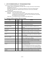
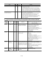
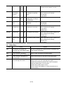
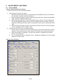
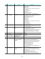
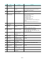
MP280 / MP287 / MP288
MP495 / MP497 / MP498
SERVICE REFERENCE MANUAL
In this manual, only the major differences from the base machines, MP240 / MP245, MP260 / MP268,
and MP480 / MP486, are given. For other information, refer to the "MP240 / MP245, MP260 / MP268,
MP480 / MP486 Simplified Service Manual" (QY8-13BV-010).
QY8-13CW-000
Rev. 00: June 2010
Canon Inc.
(1/15)
TABLE OF CONTENTS
1.
2.
LIST OF ERROR DISPLAY / TROUBLESHOOTING
1-1.
Operator Call Error (Alarm LED Lit In Orange)
1-2.
Service Call Error (Cyclic Blinking in Orange (Alarm LED) and Green (ON LED)
1-3.
Other Error
ADJUSTMENT / SETTINGS
2-1.
Service Mode
2-2.
User Mode
2-3.
Notes on Part Replacement
(2/15)
1.
LIST OF ERROR DISPLAY / TROUBLESHOOTING
Errors and warnings are displayed by the following ways:
- Operator call errors are indicated by the Alarm LED lit in orange, and the error and its solution
are displayed on the LCD.
- Messages during printing from a computer are displayed on the MP driver Status Monitor.
- Error codes are printed in the "operator call/service call error record" area in EEPROM
information print.
Buttons valid when an operator call error occurs:
- ON button: To turn the machine off and on again.
- OK button: To clear and recover from an error. In some operator call errors, the error will
automatically be cleared when the cause of the error is eliminated, and pressing
the OK button may not be necessary.
- Stop button: To cancel the job at error occurrence, and to clear the error.
1-1. Operator Call Error (Alarm LED Lit In Orange)
Error
Error 7-segment
code
LCD
No paper in the rear tray.
Paper jam.
Paper output tray open.
[1000] E02
[1300] E03
[1251] E03
Ink cartridge not installed, or
not properly installed.
[1401] E05
Ink cartridge temperature
[1403] E05
sensor error.
Non-supported ink cartridge is [1485] E05
installed.
Ink cartridge in a wrong
position.
[1486] E07
Multiple ink cartridges of the
same color installed.
[1487] E07
Ink cartridge hardware error
[1682] E15
Ink cartridge not recognized.
[1684] E14
The remaining ink amount
unknown.
[1686] E13
Ink cartridge not completely
installed.
[1687] E04
Solution
Set the paper in the rear tray, and press the OK button.
Remove the jammed paper, and press the OK button.
There may be an obstacle in front of the machine. Remove
it, if any, and press the OK button.
Install the ink cartridge properly. If the error is not cleared,
the ink cartridge may be defective. Replace the ink
cartridge.
Re-set the ink cartridge. If the error is not cleared, the ink
cartridge may be defective. Replace the ink cartridge.
A non-supported ink cartridge is installed. Install the
supported ink cartridge. If the error is not cleared, the ink
cartridge may be defective. Replace the ink cartridge.
Install the ink cartridge in the correct position. If the error is
not cleared, the ink cartridge may be defective. Replace
the ink cartridge.
Confirm that each ink cartridge is installed in the correct
position. If the error is not cleared, the ink cartridge may be
defective. Replace the ink cartridge.
Re-set the ink cartridge. If the error is not cleared, the ink
cartridge may be defective. Replace the ink cartridge.
A non-supported ink cartridge is installed. Install the
supported ink cartridge.
Replace the ink cartridge. Printing with an empty ink tank
can damage the machine.
To continue printing without replacing the ink cartridge,
press the Stop/Reset button for 5 sec. or longer. (After the
operation, it is recorded in the machine EEPROM that the
function to detect the remaining ink amount was disabled.)
Re-set the ink cartridge. If the error is not cleared, the ink
cartridge may be defective. Replace the ink cartridge.
(3/15)
Error
Error 7-segment
code
LCD
No ink.
[1688] E16
Warning: The ink absorber
becomes almost full.
[1700] E08
Solution
Replace the ink cartridge. Printing with an empty ink tank
can damage the machine.
To continue printing without replacing the ink cartridge,
press the Stop/Reset button for 5 sec. or longer. (After the
operation, it is recorded in the machine EEPROM that the
function to detect the remaining ink amount was disabled.)
Replace the ink absorber, and reset the ink absorber
counter. (See 2-1, "Service Mode.")
Pressing the Stop/Reset button will exit the error, and
enable printing without replacing the ink absorber.
However, when the ink absorber becomes full, no further
printing can be performed unless the applicable ink
absorber is replaced.
1-2. Service Call Error (Cyclic Blinking in Orange (Alarm LED) and Green (ON LED)
Cycles of
blinking in
orange and
green
Error
Error 7-seg.
code LCD
Conditions
2 times
Carriage error [5100] P02
An error occurred in the
carriage encoder signal.
3 times
Line feed error [6000] P03
An error occurred in the LF
encoder signal.
5 times
ASF cam
sensor error
[5700] P05
This error takes place when
feeding paper from the rear
tray after an error occurred
in the rear tray cam sensor.
6 times
Internal
temperature
error
[5400] P06
The internal temperature is
not normal.
(4/15)
Solution
(Replacement of listed parts, which are
likely to be faulty)
1) Confirm that no foreign material is in the
area where the carriage moves.
2) Clean the timing slit film.
If it cannot be cleaned, replace it.
3) Replace the following items (listed in the
order of likeliness to be faulty):
- Carriage unit
- Logic board
1) Perform the following for the timing slit
disk film:
- Clean it.
- Re-attach it, if peeled off.
- Replace it, if it cannot be cleaned, or if
it is deformed or damaged.
2) Replace the following items (listed in the
order of likeliness to be faulty):
- Logic board
- Drive unit
1) Confirm that no foreign material is
around the drive gear on the side of the
drive unit.
2) Replace the following items (listed in the
order of likeliness to be faulty):
- Drive unit
- Logic board
Replace the logic board.
7 times
Ink absorber
full
Japan: P07
[5B00]
Others:
[5B01]
[5200] P08
8 times
Print head
temperature
rise error
9 times
EEPROM error [6800] P09
[6801]
10 times
VH monitor
error
20 times
Other
[6500] P20
hardware error
22 times
Scanner error [5011] P22
23 time
Scanner motor [5012] P22
error
[B200] P10
The ink absorber becomes Replace the ink absorber (ink absorber kit),
full.
and reset the ink absorber counter.
The print head temperature Replace the following items (listed in the
exceeded the specified
order of likeliness to be faulty):
value.
- Ink cartridge
- Logic board
A problem occurred in
Replace the logic board.
reading from or writing to
the EEPROM.
The print head voltage is
Replace the following items:
abnormal.
- Ink cartridge
- Logic board
An unidentified error or a
Replace the following item (listed in the
network error occurred.
order of likeliness to be faulty):
- Logic board
- WLAN board
The scanner unit is faulty. Replace the following items (listed in the
order of likeliness to be faulty):
- Scanner unit
- Logic board
The scanner motor is faulty. Replace the following items (listed in the
order of likeliness to be faulty):
- Scanner unit
- Logic board
1-3. Other Error
7-segment
LCD
E20
E23
E24
E50
Cause
Solution
The wireless LAN setting was
Wait until the settings being performed were completed, then
attempted while other settings were try the wireless LAN setting.
being performed.
In WPS wireless LAN setting,
Wait for a while, and perform the setting again.
multiple access points were detected.
In WPS wireless LAN setting, an
Confirm the access point, and perform the setting again.
error occurred.
The machine failed in scanning the Press the Stop/Reset button to clear the error, perform the
print head alignment sheet.
following, then try the print head alignment again:
- Confirm that the sheet is placed in the correct orientation.
- Clean the platen glass, if it is smeared.
- Confirm that A4 plain paper is used.
- Print the nozzle check pattern to confirm that all the ink is
ejected properly.
(5/15)
2.
ADJUSTMENT / SETTINGS
2-1. Service Mode
< Service mode operation procedures >
Use the Service Tool on the connected computer.
1)
Start the printer in the service mode.
i.
With the machine power turned off, while pressing the Stop/Reset button, press and hold
the ON button. (DO NOT release the buttons).
ii. When the Power LED lights in green, while holding the ON button, release the Stop/Reset
button. (DO NOT release the ON button.)
iii. While holding the ON button, press the Stop/Reset button 5 times, and then release both
the ON and Stop/Reset buttons. (Each time the Stop/Reset button is pressed, the Alarm
and Power LEDs light alternately, Alarm in orange and Power in green, starting with Alarm
LED.)
iv. When the Power LED lights in green, the machine is ready for the service mode operation
and "0" is displayed on the 7-segment LCD.
Start the Service Tool on the connected computer.
i.
When a button is clicked in the Service Tool dialog box, that function is performed. During
operation of the selected function, all the Service Tool buttons are dimmed and inactive.
ii
When the operation is completed, "A function was finished." is displayed, and another
function can be selected.
iii If a non-supported function is selected, "Error!" is displayed. Click OK in the error message
dialog box to exit the error.
2)
< Service Tool functions >
(1)
(2)
(3)
(5)
(6)
(7)
(10)
(11)
(12)
(4)
(8)
(13)
(9)
(14)
(16)
(17)
(18)
(19)
(20)
(21)
(22)
(23)
(24)
(6/15)
(15)
No.
Name
Function
Remarks
(1)
Print: Test Print
Service test print
Service test print:
- Model name
- ROM version
- Ink absorber counter value (ink amount in the
ink absorber)
- USB serial number
- Destination
- EEPROM information
- Barcode (model name + destination), etc.
(2)
Print: EEPROM
EEPROM information print The dialog box opens to select the paper source.
Select Rear tray, and click OK.
EEPROM information print:
- Model name
- Destination
- ROM version
- Ink absorber counter value (ink amount in the
ink absorber)
- Print information
- Error information, etc.
(3)
Print: Nozzle Check
Nozzle check pattern print The same nozzle check pattern as the one in the
user mode is printed.
(4)
Print: Integration
Unified inspection pattern The dialog box opens to select the paper source.
print
Select Rear tray, and click OK.
The unified inspection pattern of the service test
print, EEPROM information print, and nozzle
check pattern print is printed on one sheet of
paper.
(5)
Print: CD-R
CD-R check pattern print
Not used.
(6)
Print: LF / EJECT
LF / Eject correction
pattern print
Not used.
(7)
Print: Left Margin
Left margin pattern print
Not used.
(8)
Print: Auto Cleaning
Enabling / disabling of
automatic print head
cleaning
Automatic print head cleaning prior to printing.
Select this option to enable the cleaning.
The automatic cleaning is performed prior to the
following printing when this option is enabled:
- EEPROM information print
- Nozzle check pattern print
- Left margin pattern print
- Ink absorber counter value printing after the
counter is reset
(9)
Save: EEPROM
EEPROM information
saving
Display of the EEPROM information on the
computer, or saving of the EEPROM information
to the computer.
In the MP280/MP287/MP288 and
MP495/MP497/MP498, this function is not
available if an error occurred in the machine.
(7/15)
No.
Name
Function
Remarks
(10) Cleaning:
Deep Cleaning
Print head deep cleaning
Cleaning of both Black and Color at the same
time.
(11) Clear Ink Counter:
Main
Main ink absorber counter Set a sheet of A4 or Letter sized plain paper. After
resetting
the ink absorber counter is reset, the counter
value is printed automatically.
(12) Clear Ink Counter:
Platen
Platen ink absorber
counter resetting
Not used.
(13) Operation:
EEPROM Clear
EEPROM initialization
The following items are NOT initialized, and the
shipment arrival flag is not on:
- Destination settings
- Ink absorber counter value
- USB serial number
- Ink cartridge region code
- Record of ink absorber counter resetting and
setting
- Record of repair at the production site, etc.
(14) Operation:
Panel Check
Button and LCD test
See "Button and LCD test" below.
(15) Operation:
Clear S/N
Machine serial number
clearing
The machine serial number in the EEPROM is
cleared.
Not used in regular repair servicing.
(16) Set Destination
Destination settings
Select the destination, and click Set.
ASA, AUS, BRA, CHN, CND, EMB, EUR, JPN,
KOR, LTN, TWN, USA
(17) CD-R Correction
CD / DVD print position
correction (X and Y
direction)
Not used.
(18) LF / EJECT
Correction
LF / Eject correction value Not used.
setting
(19) Auto LF / EJ
Automatic LF / Eject
correction value setting
Not used.
(20) Left Margin
Correction
Left margin correction
value setting
Not used.
(21) Ink Absorber Counter Ink absorber counter
setting
See " Ink absorber counter setting " below.
(22) Wetting Liquid
Counter
Wetting liquid counter
setting
Not used.
(23) Panel Rank
Capacitive sensor
sensitivity setting
Not used.
(24) Flatbed Scanner
Individual scanner
adjustment
Not used.
(8/15)
< Button and LCD test >
Confirm the operation after replacement of the operation panel unit or logic board.
1) Click Panel Check of the Service Tool on the connected computer.
2) Press each button of the operation panel.
Each time a button is pressed, the number displayed on the LCD increments by 1, starting with "1."
When all the buttons are pressed, "E" is displayed.
3) Press the ON button. The machine returns to be ready for selection of another function.
< Ink absorber counter setting >
Set the ink absorber counter value to a new EEPROM after the logic board is replaced in servicing.
1) Before replacement of the logic board, check the ink absorber counter value in EEPROM
information print.
2) In the Ink Absorber Counter section of the Service Tool, select Main from the Absorber
pull-down menu.
3) From the Counter Value(%) pull-down menu, select the value (in 10% increments) which is the
closest to the actual counter value confirmed before replacement of the logic board.
4) Click Set.
2-2. User Mode
Only the difference from the base models, MP240 / MP245, MP260 / MP268, and MP480 / MP486 is
the automatic print head alignment. The other functions are the same as the ones in the base
models.
< Automatic print head alignment >
The machine performs print head alignment just by scanning the printed alignment pattern as-is.
(Models with this type of print head alignment: MP250 / MP258, MP270 / MP276, MP490 / MP496,
MP280 / MP287 / MP288, MP495 / MP497 / MP498)
Function
Automatic print head
alignment
(by scanning the printed
alignment pattern)
Procedures
Perform via the machine
operation panel, or from the MP
driver Maintenance tab.
Remarks
Set a sheet of A4 or Letter sized plain
paper.
2-3. Notes on Part Replacement
< Preventive replacement of ink absorber >
Replace the ink absorber in accordance with the guideline below, even when the ink absorber is not
full. (For details, refer to Service Information #Q-12E/J-0188.)
< Guideline for preventive replacement of ink absorber >
Replace the ink absorber when it falls in either Criteria 1 or Criteria 2.
Criteria
Purpose
How to know the criteria values
Criteria 1:
To avoid re-repair for ink absorber
For 2009 2H or earlier products:
The ink absorber life* is 2 replacement in a short period of
EEPROM information print and
years or less.
time after repair for other reasons.
the quick reference table (Service
Information #Q-12E/J-0188)
For 2010 1H and later products:
EEPROM information print
Criteria 2:
To prevent ink leakage during
EEPROM information print
The ink absorber counter
return of the repaired printer to
value is 80% or more.
users.
(9/15)
* The estimated number of months until the ink absorber will become full
How to judge:
Print the EEPROM information, and check the "D" (ink absorber counter) and "DF" (ink absorber life)
values.
Step 1: Is "D" 80% or more?
Yes (80% or more)
No (less than 80%)
Step 2: Is "DF" 24 or more?
No (less than 24 months)
Yes (24 months or more)
->
->
Replace the ink absorber.
Proceed to Judgment 2.
->
->
Replace the ink absorber.
No need to replace the ink absorber.
How to read the EEPROM information print:
D: ink absorber counter value
Replace the ink absorber when
the value is 80 or more.
DF: ink absorber life
Replace the ink absorber when
the value is less than 24.
(10/15)