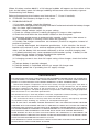
1
277-999
ELECTRIC CORP.
801 BUSINESS CENTER DRIVE • MOUNT PROSPECT, ILLINOIS • 800-621-5485 • Ext. 322
Send Warranty Product Repairs to: 605 South Vermilion, Suite C, Brownsville, TX 78521-6851
Call Customer Service if you have questions: 1-800-621-5485
A.
IMPORTANT SAFETY INSTRUCTIONS
1. SAVE THESE INSTRUCTIONS -This manual contains
important safety and operating instructions for battery charger Model SE-1072.
A BATTERY CHARGER RECEIVES AC POWER FROM THE ELECTRIC OUTLET, AND
DELIVERS DC CURRENT TO THE BATTERY.
2. Before using battery charger, read all instructions and cautionary markings on (1)
battery charger, (2) battery, and (3) product using battery.
3. CAUTION - To reduce risk of injury, charge only lead acid type rechargeable batteries.
Other types of batteries may burst, causing personal Injury and damage.
4. Use of an attachment not recommended or sold by the battery charger manufacturer
may result in a risk of fire, electric shock, or injury to persons.
5. To reduce risk of damage to electric plug and cord, pull by plug rather than cord when
disconnecting charger.
6. Make sure cord is located so that it will not be stepped on, tripped over, or otherwise
subjected to damage or stress.
7. An extension cord should not be used unless absolutely necessary. Use of improper
extension cord could result in a risk of fire and electric shock. If extension cord must be
used, make sure:
(a) That pins on plug of extension cord are the same number, size and shape as those
of plug on charger;
(b) That extension cord is properly wired and In good electrical condition; and
(c) That wire size is large enough for AC ampere rating of charger as specified below:
AWG SIZE OF CORD
AC INPUT RATING, AMPERES
Equal to or
Greater than
6
8
10
but less than
25
8
10
12
18
18
16
Length of Cord, Feet
50
100
150
16
14
14
12
12
10
10
10
8
8. Do not operate charger with damaged cord or plug - replace them immediately.
9. Do not operate charger if it has received a sharp blow, been dropped, or otherwise
damaged in any way; take it to a qualified service man.
10. Do not disassemble charger; take it to a qualified serviceman when service or repair
is required. Incorrect reassembly may result in a risk of electric shock or fire.
11. To reduce risk of electric shock, unplug charger from outlet before attempting any
maintenance or cleaning. Turning off controls will not reduce this risk.
B. WARNING - RISK OF EXPLOSIVE GASES
1. WORKING IN VICINITY OF A LEAD-ACID BATTERY IS DANGEROUS. BATTERIES
GENERATE EXPLOSIVE GASES DURING NORMAL BATTERY OPERATION. FOR THIS
REASON, IT IS OF UTMOST IMPORTANCE THAT EACH TIME BEFORE USING YOUR
CHARGER, YOU READ THIS MANUAL AND FOLLOW THE INSTRUCTION EXACTLY.
Page 1
2. To reduce risk of battery explosion, follow these Instructions and those published by
battery manufacturer and manufacturer of any equipment you intend to use in vicinity of
battery. Review cautionary marking on these products and on engine.
C. PERSONAL PRECAUTIONS
1. Someone should be within range of your voice or close enough to come to your aid when
you work near a lead-acid battery.
2. Have plenty of fresh water and soap nearby for use if battery acid contacts skin, clothing
or eyes.
3. Wear complete eye protection and clothing protection. Avoid touching eyes while
working near battery.
4. If battery acid contacts skin or clothing, wash immediately with soap and water. If acid
enters eye, immediately flood eye with running cold water for at least 10 minutes and get
medical attention immediately.
5. NEVER smoke or allow a spark or flame in vicinity of battery or engine.
6. Be extra cautious not to drop a metal tool onto battery. It might spark or short-circuit
battery or other electrical part that may cause explosion.
7. Remove personal metal items such as rings, bracelets, necklaces, and watches when
working with a lead-acid battery. A lead-acid battery can produce a short-circuit current
high enough to weld a ring or the like to metal, causing a severe burn.
8. Use charger for charging a LEAD-ACID battery only. It is not intended to supply power
to a low-voltage electrical system other than in an automotive application. Do not use
battery charger for charging dry-cell batteries that are commonly used with home
appliances. These batteries may burst and cause injury to persons and damage to
property.
9. NEVER charge a frozen battery.
D. PREPARING TO CHARGE
1. If necessary to remove battery from vehicle to charge, always remove grounded
terminal from battery first. Make sure all accessories in the vehicle are off, so as not to
cause an arc.
2. Be sure area around battery is well ventilated while battery is being charged. Gas can
be forcefully blown away by using a piece of cardboard or other nonmetallic material as
a fan.
3. Clean battery terminals. Be careful to keep corrosion from coming in contact with eyes.
4. Add distilled water in each cell until battery acid reaches level specified by battery
manufacturer. This helps purge excessive gas from cells. Do not overfill. For a battery
without cell caps, carefully follow manufacturer’s recharging instructions.
5. Study all battery manufacturer’s specific precautions such as removing or not removing
cell caps while charging and recommended rates or charge.
6. Determine voltage of battery by referring to car owner’s manual and make sure that
output voltage selector switch is set at correct voltage. If charger has adjustable charge
rate, charge battery initially at lowest rate.
E. CHARGER LOCATION
1. Locate charger as faraway from battery as DC cables permit.
2. Never place charger directly above battery being charged; gases from battery will
corrode and damage charger.
3. Never allow battery acid to drip on charger when reading gravity or filling battery.
4. Do not operate charger in a closed-in area or restrict ventilation in any way.
5. Do not set a battery on top of charger.
Page 2
6. Do not expose charger to rain or snow.
F. DC CONNECTION PRECAUTIONS
1. Connect and disconnect DC output clips only after setting any charger switches to off
position and removing AC cord from electric outlet. NEVER ALLOW CLIPS TO TOUCH EACH
OTHER.
2. Attach clips to battery posts and twist or rock back and forth several times to make a
good connection. This tends to keep clips from slipping off terminals and helps to reduce
risk of sparking.
G. FOLLOW THESE STEPS WHEN BATTERY IS INSTALLED IN VEHICLE. A SPARK NEAR
BATTERY MAY CAUSE BATTERY EXPLOSION. TO REDUCE RISK OF SPARK NEAR
BATTERY, DO AS FOLLOWS:
1. Position AC and DC cords to reduce risk of damage by hood, door, or moving engine
part.
2. Stay clear of fan blades, belts, pulleys, and other parts that can cause Injury to persons.
3. Check polarity of battery posts. POSITIVE (POS, P, +) battery post usually has larger
diameter than NEGATIVE (NEG, N, -) post.
4. Determine which post of battery is grounded (connected to the chassis). If negative
post is grounded to chassis (as in most vehicles), see G.5. If positive post is grounded
to the chassis, see G.6.
5. For negative-grounded vehicle, connect POSITIVE (RED) clip from battery charger to
POSITIVE (POS, P, +) ungrounded post of battery. Connect NEGATIVE (BLACK) clip to
vehicle chassis or engine block away from battery. Do not connect clip to carburetor, fuel
lines, or sheet-metal body parts. Connect to a heavy gage metal part of the frame or engine
block.
6. For positive-grounded vehicle, connect NEGATIVE (BLACK) clip from battery charger
to NEGATIVE (NEG, N, -) ungrounded post of battery. Connect POSITIVE (RED) clip to
vehicle chassis or engine block away from battery. Do not connect clip to carburetor, fuel
lines, or sheet-metal body parts. Connect to a heavy gage metal part of the frame or engine
block.
7. When disconnecting charger, turn switches to off, disconnect AC cord, remove clip
from vehicle chassis, and then remove clip from battery terminal, in that order.
8. See operating instructions for length of charge information.
H. FOLLOW THESE STEPS WHEN BATTERY IS OUTSIDE VEHICLE. A SPARK NEAR THE
BATTERY MAY CAUSE BATTERY EXPLOSION. TO REDUCE RISK OF A SPARK NEAR
BATTERY, DO AS FOLLOWS:
1. Check polarity of battery posts. POSITIVE (POS, P, +) battery post usually has a larger
diameter than NEGATIVE (NEG, N, -) post.
2. Attach at least a 24-inch-long 6-gauge (AWG) insulated battery cable to NEGATIVE
(NEG, N, - ) battery post.
3. Connect POSITIVE (RED) charger clip to POSITIVE (POS, P, +) post of battery.
4. Position yourself and the free end of the 24 inch cable as far away from battery as
possible; then connect NEGATIVE (BLACK) charger clip to free end of cable. Face away
from battery when doing this.
5. When disconnecting charger, always do so in reverse sequence of above procedure.
Break first connection while as far away from battery as practical.
6. A marine (boat) battery must be removed and charged on shore. To charge it on board
requires equipment specially designed for marine use.
Page 3
I.
GROUNDING AND AC POWER CORD CONNECTION INSTRUCTIONS
Charger should be grounded to reduce risk of electric shock. Charger is equipped with
an electric cord having an equipment-grounding conductor and a grounding plug. The plug
must be plugged into an outlet that is properly Installed and grounded in accordance with
all local codes and ordinances.
DANGER - Never alter AC cord or plug provided - if it will not fit outlet, have proper outlet
installed by a qualified electrician. improper connection can resuIt In a risk of an electric
shock.
This battery charger is for use on a nominal 120-volt circuit, and has a grounding plug that
looks like the plug Illustrated In sketch A in Figure 1. A temporary adapter, which looks like
the adapter illustrated In sketches B and C, may be used to connect this plug to a two-pole
receptacle as shown In sketch B If a properly grounded outlet is not available. The
temporary adapter should be used only until a properly grounded outlet can be installed
by a qualified electrician.
DANGER - Before using adapter as Illustrated, be certain that center screw of outlet plate
is grounded. The green-colored rigid ear or lug extending from adapter must be connected
to a properly grounded outlet - make certain it is grounded. If necessary, replace original
outlet cover plate screw with a longer screw that will secure adapter ear or lug to outlet
cover plate and make ground connection to grounded outlet.
FIGURE 1
GROUNDING METHODS
J. OPERATION INSTRUCTIONS
The output supply is protected by a 30 Amp quick-blow fuse. This fuse may blow instantly
due to short circuit of the output, reverse battery connection or excessive overloading.
Replace only with a 30 Amp, 125/250 volt quick-blow fuse.
K. OUTPUT VOLTAGE SELECTOR SWITCH
Set output voltage selector switch to match the sum of battery voltages. Connect batteries
in series only. Selector switch is in 12 volt steps only. Never connect an odd number of
6 volt batteries. Two 6 volt batteries series-connected equal one 12 volt battery.
Combinations of 6 and 12 volt batteries may be charged.
Page 4
Selector
Switch
12V
24V
36V
48V
60V
72V
12 Volt
Battery
1
2
3
4
5
6
6 Volt
Battery
2
4
6
8
10
12
L. AMP SELECTOR SWITCH
The charge rate of either 5 or 10 Amp maybe selected for any selected output
voltage.
M. CHARGE PERIOD AND TIMER SETTING
The approximate time required to bring a battery to a fully charged state depends upon
the number of Ampere Hours (AH) depleted from the battery. AH’s are determined by
multiplying the number of hours times the number of Amps supplied by a battery to a load.
For example: If a load was connected to a battery which drew 10 Amps for a period of
4 hours, the battery will have supplied 40 AH. The approximate recharge time would then
be calculated by dividing the 40 AH depleted from the battery, by the ampere charge rate
of the battery charger. Add an extra 20% for tapering of the charge rate and battery
recharge inefficiency.
The required charge period for the above conditions would be approximately 5 hours. That
Is, 10 Amps (depleted) x 4 (discharge period in hours) - 10 Amp (charger output rate) x
1.20 = 4.8 hours which = 4 hours and 48 minutes.
Another method to determine the required charge period is by means of performing a
hydrometer test. Measure the specific gravity of the electrolyte, corrected for 80° F (26.7°
C), of each cell.
Two common types of hydrometers are:
Types calibrated in terms of specific gravity (a common scale being 1.120 to 1.265) or the
type which use four colored balls to Indicate state of charge. There are many types
available. Read and follow the instructions that are provided with each type.
Specific Gravity Value
State of Charge
Floating Balls
1.265
1.225
1.190
1.155
1.120
100%
75%
50%
25%
Discharged
4
3
2
1
*
*No balls float in the barrel of the hydrometer.
If you have a 70H rated battery, and its hydrometer reading indicates a 25% state of charge,
then 52.5 AH are needed to bring the battery back to 100% of charge.
(70AH - (.25 x 70)) = 52.5 AH
Charge period would be calculated as follows.
52.5 AH -1- 10 (amp rate) x 1.20 (120%) = 6.3 hours or 6 hours and 18 minutes. The timer would
be set to 6.5 hours for this example.
If the charge rate switch is set to 5 Amps the charge time will be twice as long.
Indications of a fully charged battery are:
When the ammeter indicates the charge rate has tapered to approximately one half the charger
rated output.
A hydrometer reading of the specific gravity of the electrolyte (fluid) of the battery in good
condition should be between 1.250 and 1.285.
Page 5
When A battery reaches 80-85% of full charge, bubbles will appear on the surface of the
fluid. As the battery nears full charge, bubbling will become more noticeably vigorous.
Disconnecting from Battery:
Before disconnecting from battery read Instructions F, G and H carefully.
N. STORAGE: Store battery charger in a dry area.
P. PROBLEM CHECKLIST
1. If no meter reading, check the following:
a. Remove the charger power cord plug from the AC outlet and recheck the battery charger
clips for clean, tight connections.
b. Check voltage selector switch for proper setting.
c. Check for voltage at the AC outlet by plugging in a lamp or other appliance.
d. Check the fuse within the fuse holder located on the front panel.
2. If Ammeter pointer moves to extreme right, remains a short time, then returns to
zero, accompanied by a clicking sound, check the following:
a. Possibly, the charger connections are reversed. (Positive to negative, instead of
positive to positive).
b. A severely discharged, but otherwise good battery. In this situation, the circuit
breaker will continue to cycle and the ammeter pointer will swing from one side to the
other, until the battery has recovered sufficiently to allow a normal charging rate.
c. A defective battery may cause repeated circuit breaker cycling. A battery in this
condition will not accept a charge and should be replaced.
d. Check voltage switch for proper setting.
3. If charging current is less than full output rating of the charger, check the following:
a. Perhaps battery is partially charged.
b. Perhaps battery is sulphated and will not accept full charge rate.
c. Perhaps power line is providing low AC supply voltage.
LIMITED WARRANTY
SCHUMACHER ELECTRIC CORPORATION, 801 BUSINESS CENTER DRIVE, MT. PROSPECT,
ILLINOIS 60056-2179 MAKES THIS LIMITED WARRANTY TO THE ORIGINAL PURCHASER AT
RETAIL OF THIS PRODUCT THIS LIMITED WARRANTY IS NOT TRANSFERABLE.
Schumacher Electric Corporation warrants this battery charger for two years from date of
purchase at retail against defective material or workmanship. If such should occur, the unit will be
repaired or replaced at the option of the manufacturer. It is the obligation of the purchaser to
forward the unit together with proof of purchase, transportation and/or mailing charges prepaid to
the manufacturer or its authorized representative.
This limited warranty is void if the product is misused, subjected to careless handling, or repaired
by anyone other than the manufacturer or its authorized representative.
The manufacturer makes no warranty other than this limited warranty and expressly excludes
any implied warranty including any warranty for consequential damages.
THIS IS THE ONLY EXPRESS LIMITED WARRANTY AND THE MANUFACTURER NEITHER
ASSUMES NOR AUTHORIZES ANYONE TO ASSUME OR MAKE ANY OTHER OBLIGATION
TOWARDS THE PRODUCT OTHER THAN THIS EXPRESS LIMITED WARRANTY. THE MANUFACTURER MAKES NO WARRANTY OF MERCHANTABILITY OR FITNESS FOR PURPOSE OF
THIS PRODUCT AND EXPRESSLY EXCLUDES SUCH FROM THIS LIMITED WARRANTY.
SOME STATES DO NOT ALLOW THE EXCLUSION OR LIMITATION OF INCIDENTAL OR
CONSEOUENTIAL DAMAGES OR LENGTH OF IMPLIED WARRANTY SO THE ABOVE LIMITATIONS OR EXCLUSIONS MAY NOT APPLY TO YOU.
THIS WARRANTY GIVES YOU SPECIFIC LEGAL RIGHTS AND YOU MAY ALSO HAVE OTHER
RIGHTS WHICH VARY FROM STATE TO STATE.
Page 6