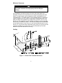
1
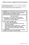
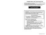
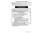
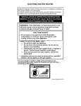
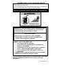
POWERED DIRECT VENT GAS WATER HEATER A Spanish language version of these instructions is available by contacting the company listed on the rating plate. La version espanola de estas instrucciones se puede obtener al escribirle a la fabrica cuyo nombre aparece en la placa de especificaciones. INSTALLATION AND OPERATING INSTRUCTION MANUAL WARNING: If the information in these instructions is not followed exactly, a fire or explosion may result causing property damage, personal injury, or death. FOR YOUR SAFETY Do not store or use gasoline or other flammable, combustible, or corrosive vapors and liquids in the vicinity of this or any other appliance. WHAT TO DO IF YOU SMELL GAS Do not try to light any appliance. Do not touch any electrical switch; do not use any phone in your building. Immediately call your gas supplier from a neighbor’s phone. Follow the gas supplier's instructions. If you cannot reach your gas supplier, call the fire department. Installation and service must be performed by a qualified installer, service agency or the gas supplier. For your family’s comfort, safety and convenience we recommend this water heater be installed and serviced by a plumbing professional. 238-47936-00F REV 7/12 CONGRATULATIONS! You have just purchased one of the finest water heaters on the market today! This installation, operation and instruction manual will explain in detail the installation and maintenance of your new Powered Direct Vent Gas Water Heater. We strongly recommend that you contact a plumbing professional for the installation of this water heater. We require that you carefully read this manual, as well as the enclosed warranty, and refer to it when questions arise. If you have any specific questions concerning your warranty, please consult the plumbing professional from whom your water heater was purchased. For your records we recommend that you write the model, serial number and installation date of your water heater in the maintenance section in the back of this manual. This manual should be kept with the water heater. Special Flammable Vapor Ignition Resistant System: This water heater is equipped with a Flammable Vapor Ignition Resistant System. In the event of improper usage or storage of gasoline or other flammable materials in the location where the water heater is installed, the technology will resist ignition of the flammable vapors outside the confines of the water heater. The Flammable Vapor Ignition Resistant System features: Flammable Vapor Sensor. Automatic Ignition Device. Sight Window to observe operation of pilot and burner. FOR YOUR SAFETY: Activation of the Flammable Vapor Ignition Resistant System occurs when flammable vapors are present in the room where the water heater is installed. If flammable vapors are detected and/or sensed: Do not try to light any appliance. Do not touch any electrical switch; Do not use any phone in your building. Leave the premises and immediately call the fire department from a neighbor’s phone. Follow the fire department’s instructions. Once the flammable vapor has been evacuated, contact your plumbing professional or the manufacturer for further instructions. Replacement of a Flammable Vapor Ignition Resistant System equipped water heater due to a flammable vapor shutdown is not covered under the terms of the limited warranty. 2 TABLE OF CONTENTS GENERAL INFORMATION................................................................. page 4 INSTALLATION. ................................................................................. Locating The Water Heater ......................................................... Minimum Clearances .................................................................. Venting ......................................................................................... Specifications for 48 Gal. (181.6 L) 65 Gal. (246.8 L) 75 Gal. (283.9 L) ..................................................................... Specifications for 40 Gal. (151.4 L) 50 Gal. (189.2 L) ..................................................................... Vent pipe preparation and joining ................................................... Water Connections...................................................................... Gas Connections ......................................................................... Electrical Connections................................................................ Wiring Diagram...................................................................... 25 36 37 40 41 42 GENERAL OPERATION .................................................................... Lighting and Shutdown Instructions ......................................... Thermostat Adjustment .............................................................. Burner Flame Check ................................................................... 43 44 45 46 MAINTENANCE .................................................................................. 47 TROUBLESHOOTING ........................................................................ 51 PARTS LIST AND PARTS LIST DRAWING ...................................... 53 INSTALLATION INSTRUCTIONS FOR POTABLE WATER AND SPACE HEATING ............................................................................... 54 NOTES ................................................................................................ 55 3 5 5 8 8 13 GENERAL INFORMATION This gas-fired water heater’s design is certified by CSA International under the American National Standard Z21.10.1 and CSA 4.1-M, most current editions at the time of manufacture. This water heater must be installed in accordance with local codes or, in the absence of local codes, the National Fuel Gas Code, ANSI Z223.1-Latest Edition) and/or in Canada CAN/CGA B149 Installation Codes (Latest Editions). The warranty for this water heater is in effect only when the water heater is installed, adjusted, and operated in accordance with these Installation and Operating Instructions. The manufacturer will not be held liable for any damage resulting from alteration and/or failure to comply with these instructions. This water heater is not design certified for installation in a mobile home. Such an installation may create a hazardous condition and will nullify the warranty. CAUTION Incorrect operation of this appliance may create a hazard to life and property and will nullify the warranty. Do not use this appliance if any external part has been submerged in water. You should contact a qualified service technician to inspect the appliance and to replace any part of the control system including the combination gas control which has been submerged in water. DANGER Do not store or use gasoline or other flammable, combustible, or corrosive vapors and liquids in the vicinity of this or any other appliance. IMPORTANT Before proceeding, please inspect the water heater and its components for possible damage. DO NOT install any water heater with damaged components. If damage is evident then please contact the supplier where the water heater was purchased or the manufacturer listed on the rating plate for replacement parts. Make sure that you check the rating plate and combination gas control on the water heater to be certain that the type of gas being supplied corresponds with the marking on the rating plate and combination gas control. 4 General Information continued- A sacrificial anode is used to extend tank life. The removal of this anode, for any reason, will nullify the warranty. In areas where water is unusually active, an odor may occur at the hot water faucet due to a reaction between the sacrificial anode and the impurities in the water. If this should happen, an alternative anode may be purchased from the supplier that installed this water heater. This will minimize the odor while protecting the tank. Additionally, the water heater should be flushed with appropriate dissolvers to eliminate any bacteria. INSTALLATION Locating The Water Heater WARNING Water heaters are heat producing appliances. To avoid damage or injury, do not store materials against the water heater or vent-air intake system. Use proper care to avoid unnecessary contact (especially by children) with the water heater and vent-air intake components. UNDER NO CIRCUMSTANCES MUST FLAMMABLE MATERIALS, SUCH AS GASOLINE OR PAINT THINNER BE USED OR STORED IN THE VICINITY OF THIS WATER HEATER, VENT-AIR INTAKE SYSTEM OR IN ANY LOCATION FROM WHICH FUMES COULD REACH THE WATER HEATER OR VENT-AIR INTAKE SYSTEM. DO NOT install the water heater in any location where gasoline or flammable vapors are likely to be present. Water heaters in residential garages must be installed and located, or protected, to avoid physical damage. For other installations refer to local codes. In the absence of local codes, the water heater must be installed in compliance with the National Fuel Gas Code, (ANSI Z223.1- Latest Edition), or in Canada CAN/CGA B149.1 Natural Gas Installation Code (Latest Edition) or CAN/CGA B149.2 Propane Installation Code (Latest Edition). The location of this water heater is of the utmost importance. Before installing this water heater, read the installation section of these instructions. After reading these installation and operating instructions, select a location for the water heater where the floor is level and is easily accessible to gas and water supply lines. DO NOT locate the water heater where water lines could be subjected to freezing temperatures. Make sure the cold water pipes are not located directly above the gas control so that condensate during humid weather does not drip on the controls. 5 Installation (Locating The Water Heater) continued- Water heater corrosion and component failure can be caused by the heating and breakdown of airborne chemical vapors. Examples of some typical compounds that are potentially corrosive are: spray can propellants, cleaning solvents, refrigerator and air conditioning refrigerants, swimming pool chemicals, calcium and sodium chloride, waxes and process chemicals. These materials are corrosive at very low concentration levels with little or no odor to reveal their presence. NOTE: DAMAGE TO THE WATER HEATER CAUSED BY EXPOSURE TO CORROSIVE VAPORS IS NOT COVERED BY THE WARRANTY. DO NOT OPERATE THE WATER HEATER IF EXPOSURE HAS OR WILL OCCUR. DO NOT STORE ANY POTENTIALLY CORROSIVE COMPOUNDS IN THE VICINITY OF THE WATER HEATER. To comply with NSF requirements this water heater is to be: a) Sealed to the floor with sealant, in a smooth and easily cleanable way, or b) Installed with an optional leg kit that includes legs and/or extensions that provide a minimum clearance of 6” beneath the water heater. WARNING Liquefied petroleum gases/propane gas are heavier than air and will remain at floor level if there is a leak. Basements, crawl spaces, closets, and areas below ground level will serve as pockets for accumulation of leaking gas. Before lighting, smell all around the appliance area for gas. Be sure to smell next to the floor. IF YOU SMELL GAS: Do not try to light any appliance. Do not touch any electric switch; do not use any telephone in your building. Immediately call your gas supplier from a neighbor’s telephone. Follow the gas supplier’s instructions. If you cannot reach your gas supplier, call the fire department. DO NOT OPERATE APPLIANCE UNTIL THE LEAKAGE IS CORRECTED! 6 Installation (Locating The Water Heater) continued- WARNING DO NOT ATTEMPT TO LIGHT ANY GAS APPLIANCE IF YOU ARE NOT CERTAIN OF THE FOLLOWING: Liquefied petroleum gases/propane gas and natural gas have an odorant added by the gas supplier that aids in the detection of the gas. Most people recognize this odor as a “sulfur” or “rotten egg” smell. Other conditions, such as “odorant fade” can cause the odorant to diminish in intensity, or “fade”, and not be as readily detectable. If you have a diminished sense of smell, or are in any way unsure of the presence of gas, immediately contact your gas supplier from a neighbor’s telephone. Gas detectors are available. Contact your gas supplier, or plumbing professional, for more information. The water heater must be located close enough to the outside wall to keep the venting distance within the maximum distance described in the installation instructions. Read the venting section in this installation instruction manual before locating the water heater. This water heater must be located in an area where leakage of the tank or water line connections and the combination temperature and pressure relief valve will not result in damage to the area adjacent to the water heater or to lower floors of the structure. When such locations cannot be avoided, a suitable drain pan adequately piped for proper drainage must be installed under the water heater. The drain pan, as described above, can be purchased from your plumbing professional. The drain pan must be piped to an adequate drain. The piping must be at least 3/4 inch (1.9 cm) in diameter and pitched for proper drainage. It is recommended that a minimum clearance of four (4) inches (10.2 cm) be provided on the side of the water heater for servicing and maintenance of the combination temperature and pressure relief valve. This water heater MUST be installed indoors out of the wind and weather. Note: For California installation this water heater must be braced, anchored, or strapped to avoid falling or moving during an earthquake. See instructions for correct installation procedures. Instructions may be obtained from DSA Headquarters Office, 1102 Q Street, Suite 5100, Sacramento, CA 95811. 7 Minimum Clearances WARNING Failure to adhere to these installation and operating instructions may create a hazard to life and property and will nullify the warranty. This installation must allow access to the front of the water heater and adequate clearance must be provided for servicing and operating this water heater. The water heater may be installed on either a combustible or noncombustible floor. If the water heater is to be installed directly on carpeting, it must be installed on top of a metal or wood panel extending beyond the full width and depth of the appliance by at least three (3) inches (7.6 cm) in any direction or, if the appliance is to be installed in an alcove or closet, the entire floor must be covered by the panel. The minimum clearances to combustibles for this water heater are: zero (0) inch (0 cm) from the sides and rear, five (5) inches (12.7 cm) from the front of the jacket, zero (0) inch (0 cm) from the vent connector and fifteen (15) inches (38.1 cm) from the jacket top. Increase distances to provide clearance for servicing. Venting Figure 1 – Direct Vent Terminal Clearances 8 Venting continuedCanadian Installations1 US Installations2 12 inches (30 cm) 12 inches (30 cm) 12 inches (30 cm) 12 inches (30 cm) *b *b A= Clearance above grade, veranda, porch, deck or balcony B= Clearance to window or door that may be opened C= Clearance to permanently closed window D= Vertical clearance to ventilated soffit located above the terminal within a horizontal distance of 2 feet (61 cm) from the center line of the terminal *b *b E= Clearance to unventilated soffit *b *b F= Clearance to outside corner *b *b G= Clearance to inside corner *b *b Clearance to each side of center line extended above meter/regulator assembly H= I= Clearance to service regulator vent outlet or oil tank vent J= Clearance to non-mechanical air supply inlet to building or the combustion air inlet to any other appliance K= Clearance to a mechanical air supply inlet L= Clearance above paved sidewalk or paved driveway located on public property M= 3 feet (91 cm) within a height 15 feet (4.6 m) above the meter/regulator assembly 36 inches (91 cm) 12 inches (30 cm) 6 feet (1.83 m) Clearance under a veranda, porch, deck, or balcony 1 7 feet (2.13 m)† 12 inches (30 cm) ‡ *b *b 12 inches (30 cm) 3 feet (91 cm) above if within 10 feet horizontally 7 feet (2.13 m)† 12 inches (30 cm) ‡ In accordance with the current CAN/CGA-B149 Installation Codes. 2 In accordance with the current ANSI Z223.1-(Latest edition)/NFPA 54 National Fuel Gas Code. † A vent shall not terminate directly above a sidewalk or paved driveway that is located between two singlefamily dwellings and serves both dwellings. ‡ Permitted only if a veranda, porch, deck or balcony is fully open on a minimum of two sides beneath the floor. *a) A minimum clearance value determined by testing in accordance with section 2.20. *b) “Clearance in accordance with local installation codes and the requirements of the gas supplier”. The vent system must terminate so that proper clearances are maintained as cited in local codes or the latest edition of the National Fuel Gas Code, ANSI Z223.1.73.4e and 7.8a, b as follows: 1. 2. 3. 4. Do not terminate near soffit vents or crawl space or other area where condensate or vapor could create a nuisance or hazard or cause property damage. Do not terminate the exhaust vent terminal where condensate or vapor could cause damage or could be detrimental to the operation of regulators, relief valves, or other equipment. Do not terminate the exhaust vent terminal over public area or walkways where condensate or vapor can cause nuisance or hazard. The vent shall terminate a minimum of 12” (25.4 cm) above expected snowfall level to prevent blockage of vent termination. 9 Venting continued- NOTICE In locations where sustained outside air temperatures are below freezing, it is possible for the vent terminations to accumulate ice build-up due to adverse local climate conditions (prevailing wind direction, wind speed, termination orientation, etc.). The optional concentric vent terminal is more resistant to this ice build-up. In more severe temperature conditions, an optional manufacturer approved air intake relief device is available and may be installed, per the instructions, to prevent nuisance shut down of the water heater. The air intake relief device may be installed with the concentric vent termination or the standard separate vent terminations. Consult the concentric vent and/or the air intake relief device instructions for installation requirements. Vent pipes serving power vented appliances are classified by building codes as “vent connectors”. Required clearances from combustible materials must be provided in accordance with information in this manual under LOCATION OF WATER HEATER and CLEARANCES, and with National Fuel Gas Code and local codes. All vent pipes and terminals are to have a 1” minimum clearance to combustibles. DO NOT use the placement of insulation or other materials in the required clearance spaces surrounding the venting to combustible material unless otherwise specified. WARNING Risk of carbon monoxide poisoning or fire due to joint separation or pipe breakage. This water heater must be properly vented and connected to an approved vent system in good condition. DO NOT operate water heater with the absence of an approved vent system. A clean and unobstructed vent system is necessary to allow noxious fumes that could cause injury or loss of life to vent safely and will contribute toward maintaining the water heater’s efficiency. The acceptance of the venting system is dependent upon full compliance with these installation instructions. Venting system must not pass through rated fire separations. The venting system must be free to expand and contract. This venting system must be supported in accordance with these instructions. 10 Venting continued- NOTICE Single Wall Polypropylene venting systems that are listed on the Bradford White website are approved for use in the water heaters covered in this instruction manual. The venting system components are ULC S636 approved and listed by a recognized agency and may be installed in the U.S. and Canada. Complete instructions for the approved venting systems can be found on the Bradford White website, bradfordwhite.com or by calling the Technical Service Department at:800-334-3393. WARNING The approved polypropylene venting system Instruction Supplement listed on the Bradford White website for each manufacturer’s venting system must be carefully read and followed by a qualified installer. Failure to properly install the vent system may result in property damage, personal injury, or death. NOTICE For installations in Canada, field supplied vent piping must comply with CAN/CGA B149.1 (latest edition) and be certified to the Standard For Type BH, Class II, 65°C, Gas Venting Systems, ULC S636. Components of this listed system shall not be interchanged with other vent systems or unlisted pipe/fittings. All components and specified primers and cements of the certified vent system must be from a single system manufacturer and not intermixed with other system manufacturer’s vent system parts. The supplied vent connector and vent termination are certified under ULC S636 and are also certified as part of the water heater. Refer to the following tables for approved venting materials, primers, and cements. All approved primers and cements are to be used within their marked time limitations. 11 Approved Venting Materials For installations in the US For installations in CANADA ULC S636 approved CAN-COM only VENTING SYSTEM schedule 40 PVC for flue gas venting rated Class II, 65°C (components provided with water heater) IPEX ULC S636 approved schedule 40 PVC (all other vent pipe/ fittings) PVC (ASTM D-2241 Schedule 40, ASTM D-1785; or Cellular Core Schedule 40 DWV, ASTM F-891) CPVC (ASTM F-411 Schedule 40) ABS (ASTM D-2235) All fittings (other than the components supplied with the water heater) should be equivalent to: PVC-DWV (ASTM-F-2665), CPVC (ASTM F-438), or ABS (ASTM D-266/3311) Approved Primers and Cements For installations in the US For installations in CANADA IPEX ULC S636 approved PVC only Primer and Cement for flue gas venting rated Class II, 65°C PVC and CPVC Primer (ASTM F-656) PVC and CPVC Cement (ASTM D-2564) ABS Primer and Cement (ASTM D-2235) 12 Venting System Condensation Condensate formation does not occur in all installations of power direct vented water heaters, but should be protected against on installations where condensation can form in the venting system. Formation of condensation in the venting system of Power Vented water heaters is dependent upon installation conditions including, but not limited to: ambient temperature and humidity of installation location; ambient temperature and humidity of venting space; vent distance and slope; and product usage. In order to effectively control condensate from adversely affecting the mechanical components of the water heater several methods may be employed: 1. For horizontal installations the vent pipe can be installed with a downward slope (not less than 1/8" (3 mm)) and away from the blower. 2. In order to prevent condensate from draining back into the blower (vertical or horizontal runs), an optional condensate kit is available as a service part (Condensate kit, p/n 239-45875-00). A factory supplied exhaust adapter with drain outlet mounts directly to the blower outlet and is secured with two hose clamps, one to the blower and the other to the vent pipe. Tubing is provided to drain any accumulated condensate away from the water heater and to a suitable drain. The kit comes complete with instructions for proper installation. PART I - Venting Specifications for: 48 Gallon (181.6L) 65 Gallon (246.0L) 75 Gallon (283.9L) This water heater is a power vented appliance and is designed to intake and exhaust the products of combustion through 3” (7.6 cm) or 4” (10.2 cm) diameter vent pipe to the outdoors. This water heater may be either vented horizontally through the wall or vertically through the roof. Use a 3” (7.6 cm) to 4” (10.2 cm) reducer to connect to the intake and outlet when using 4” (10.2 cm) vent pipe. Apply the proper cement at the joint locations. Table 1 lists the maximum vent lengths for this water heater using 3” (7.6 cm) intake and exhaust pipe. If possible, locate the water heater so that the venting length and number of elbows are kept to the minimum distance necessary to reach the outside. If the installation requires venting lengths that exceed the lengths listed for 3” (7.6 cm) vent pipe in Table 1, then use 4” (10.2 cm) vent pipe for the vent connector. 13 Venting continued- Table 2 lists the venting distances allowed with 4” (10.2 cm) diameter vent pipe. When venting with 4” (10.2 cm) vent pipe, use a 4” (10.2 cm) to 3” (7.6 cm) reducer to exit through the building wall with 3” (7.6 cm) vent pipe. Use the 3” (7.6 cm) vent terminal supplied with the water heater to terminate on the outside of the building. If the length of 3” (7.6 cm) vent pipe needed to go through the wall is greater than 14” (35.5 cm), use 4” (10.2 cm) to go through the wall and reduce to 3” (7.6 cm) vent pipe immediately after exiting the outside wall. Refer to the venting illustrations on the following pages. Make sure the vent pipe terminal elbow fitting is at least 1” (2.5 cm) away from the edge of the wall. IMPORTANT The minimum equivalent length for the exhaust portion of the vent is 7 feet. The maximum equivalent vent length for the exhaust is 60 feet for 3” diameter pipe (50 feet for the 75 gal.) and 100 feet for 4” diameter pipe (90 feet for the 75 gal.). The intake portion of the vent must be equal to or less than the vent length of the exhaust. The tables below are provided for your quick reference, some installations may require a greater number of elbows. When calculating equivalent vent length, one 90º elbow is equivalent to 5 feet. TABLE 1 - VENT CONNECTOR LENGTHS FOR 3” (7.6 cm) DIAMETER VENT PIPE # of Elbows Terminating (excl. vent term.) Through the Wall Through the Wall Through the Wall Through the Wall Through the Roof Through the Roof Through the Roof Through the Roof 1 2 3 4 0 1 2 3 Maximum straight Length ft (m) 48, 65 75 gal. gal. 55 (16.8) 45 (13.7) 50 (15.2) 40 (12.2) 45 (13.7) 35 (10.7) 40 (12.2) 30 (9.1) 60 (18.3) 50 (15.2) 55 (16.8) 45 (13.7) 50 (15.2) 40 (12.2) 45 (13.7) 35 (10.7) 14 Minimum straight Length ft (m) 2 (.6) 2 (.6) 2 (.6) 2 (.6) 7 (2.1) 7 (2.1) 7 (2.1) 7 (2.1) Venting continued- TABLE 2 -VENT CONNECTOR LENGTHS FOR 4” (10.2 cm) DIAMETER VENT PIPE Terminating # of 90 Elbows (excl. vent term.) Through the Wall Through the Wall Through the Wall Through the Wall Through the Wall Through the Roof Through the Roof Through the Roof Through the Roof Through the Roof 1 2 3 4 5 0 1 2 3 4 Maximum straight Length ft (m) 48, 65 gal. 75 gal. 95 (29.0) 90 (27.4) 85 (25.9) 80 (24.4) 75 (22.9) 100 (30.5) 95 (29.0) 90 (27.4) 85 (25.9) 80 (24.4) 85 (25.9) 80 (24.4) 75 (22.9) 70 (21.3) 65 (19.8) 90 (27.4) 85 (25.9) 80 (24.4) 75 (22.9) 70 (21.3) Min straight Length ft (m) 10 10 10 10 10 15 15 15 15 15 (3.1) (3.1) (3.1) (3.1) (3.1) (4.6) (4.6) (4.6) (4.6) (4.6) NOTE: When using 4” (10.2 cm) vent pipe, use two 4” (10.1 cm) to 3” (7.6 cm) reducers for each portion of the vent. One reducer is installed just after the blower and the other reducer is used just prior to exiting the building. Exit the building wall with 3” (7.6 cm) vent pipe using the 3” (7.6 cm) 90 vent terminal supplied. Two 45 elbows are equivalent to one 90 elbow. Figure 2 IMPORTANT All of the Venting connections must be leak checked with a soap and water solution upon initial start up of the water heater. Any leaks must be repaired before continuing operation of the water heater. 15 Venting continued- THROUGH THE WALL VENTING: (HORIZONTAL VENTING WITH STANDARD VENT TERMINALS). Cut two 3 1/2 in. (8.9 cm) diameter holes in the wall at the point where the vent connector is going to pass through the wall. Use the proper cement to secure the 90° vent terminal provided with the water heater to the vent connector. The distance between the edge of the 90° vent terminal and the exterior wall (see Figure 3) must be 1 in. (2.5 cm). The exhaust and intake must not be less than 16” (40.6 cm) apart (see figure 4a). Use the proper cement and assembly procedures to secure the vent connector joints between the terminal and the blower outlet. Provide support brackets for every 5 feet (1.5m) of horizontal vent. 3” VENT INSTALLATION 4” VENT INSTALLATION Figure 3 16 Venting continuedVent terminal configurations for through the wall venting. When venting through the wall, the exhaust terminal must exit the structure at a minimum distance of 16” (40.6 cm) from the intake terminal. The exhaust terminal must not be located below the intake terminal for any reason (see figure 4a below for examples of acceptable vent terminal configurations). Figure 4a CAUTION NEVER INSTALL AIR INTAKE ABOVE EXHAUST When local conditions present a risk of ice accumulation on the vent terminals, the configurations in 4b and 4c or the concentric termination are preferred. The air intake screen can be removed for cold installations but this may make the air intake susceptible to debris buildup from birds or other animals. If the air intake screen is removed to prevent freezing, it is recommended that the air inlet screen be installed during the spring. Figure 4b 17 Venting continued- Figure 4c IMPORTANT When using the vent terminal configuration shown in 4c the extra elbows must be accounted for in the total vent length see Table 3 or Table 4. 18 Venting continued- THROUGH THE WALL VENTING: (HORIZONTAL VENTING WITH CONCENTRIC VENT). Cut one 4 5/8 in. (11.7 cm) diameter hole in the wall at the point where the vent connector is going to pass through the wall. Use the proper cement to secure the vent terminal to the vent connector. Use the proper cement and assembly procedures to secure the vent connector joints between the terminal and the blower outlet. Provide support brackets for every 5 feet (1.5 m) of horizontal vent. IMPORTANT When using the concentric vent terminal the maximum vent length is reduced by 10 feet. Figure 5a THROUGH THE ROOF VENTING: (VERTICAL VENTING STANDARD TERMINALS). Cut the necessary holes through the roof and ceiling and install the vent connector as shown in Figure 6. Make sure that the installation meets the local codes and/or The National Fuel Gas Code ANSI Z223.1 (Latest Edition) or CGA/CAN B149 Installation Code (latest edition). 19 Venting continued- It is acceptable to install a 90 degree elbow on IPEX concentric vent terminations use with this power direct vent water heater (see Figure 12b). A short length of appropriate diameter vent pipe should be used to transition from the vent terminal to the 90 degree elbow. Approved venting materials along with primers and cements are listed at the beginning of this venting section. When the 90 degree elbow is used the equivalent length of the elbow and short length of vent pipe must be factored into the total vent/air intake pipe determinations (see Tables 1 and 2 for appropriate vent connector lengths). (B) DIMENSION MIN 12” (30.5 CM) MAX 44” (111.8 CM) Figure 5b THROUGH THE ROOF VENTING: (VERTICAL VENTING STANDARD TERMINALS). Cut the necessary holes through the roof and ceiling and install the vent connector as shown in Figure 6. Make sure that the installation meets the local codes and/or The National Fuel Gas Code ANSI Z223.1 (Latest Edition) or CGA/CAN B149 Installation Code (latest edition). 20 Venting continued- 3” VENT INSTALLATION 4” VENT INSTALLATION Figure 6 NOTE: For installations requiring both horizontal and vertical runs, the following rule must be followed: Total length of straight pipe (both horizontally and vertically) must not exceed the maximum equivalent length listed in these instructions. 21 Venting continued- THROUGH THE ROOF VENTING: (VERTICAL VENTING CONCENTRIC VENT TERMINAL): Cut the necessary holes through the roof and ceiling and install the vent connector as shown in Figure 7. Make sure that the installation meets the local codes and/or the National Fuel Gas Code ANSI Z223.1 (Latest Edition) or CAN/CGA B149 installation code (latest edition). A condensate kit must be installed when venting through the roof. Figure 7 NOTE: For installations requiring both horizontal and vertical runs, the following rule must be followed. Total length of straight pipe (both horizontally and vertically) must not exceed the equivalent length listed in these instructions. For the concentric vent terminal the maximum vent length is reduced by 10 feet. CAUTION FOR VERTICAL INSTALLATIONS WITH CONCENTRIC VENT TERMINAL, CONDENSATE KIT, P/N 239-45875-00, MUST BE USED. 22 Venting continued- THROUGH THE WALL VENTING WITH LOW GROUND CLEARANCE: When venting cannot exit through the wall at a height greater than or equal to 12” (30.5 cm) above the ground, or anticipated snow level, the installation must be modified as shown below (see Figure 8). Refer to Table 3 for maximum venting lengths using 3” (7.6 cm) vent pipe or Table 4 for maximum lengths using 4” (10.2 cm) vent pipe. The exhaust and intake terminals must not be less than 16 in. (40.6 cm) apart (see figure 4a). 3” VENT INSTALLATION 4” VENT INSTALLATION Figure 8 23 Venting continued- TABLE 3 3” (7.6 cm) VENT CONNECTOR LENGTHS FROM INSIDE WALL FOR LOW GROUND CLEARANCE INSTALLATIONS Terminating # of Elbows (excl. vent term.) (2) 90 Elbows with (1) 90 Elbow (2) 90 Elbows with (1) 90 Elbow (2) 90 Elbows with (1) 90 Elbow (2) 90 Elbows with (1) 90 Elbow Max Straight Length ft (m) Min straight Length ft (m) 48,65 gal. 75 gal. 1 40 (12.2) 30 (9.1) 5 (1.5) 2 35 (10.7) 25 (7.6) 5 (1.5) 3 30 (9.1) 20 (6.1) 5 (1.5) 4 25 (7.6) 15 (4.6) 5 (1.5) TABLE 4 4” (10.2 cm) VENT CONNECTOR LENGTHS FROM INSIDE WALL FOR LOW GROUND CLEARANCE INSTALLATIONS Terminating (Reduce 4” to 3”) (Reduce 10.1 cm to 7.6 cm) (2) 90 Elbows with (1) 90 Elbow (2) 90 Elbows with (1) 90 Elbow (2) 90 Elbows with (1) 90 Elbow (2) 90 Elbows with (1) 90 Elbow (2) 90 Elbows with (1) 90 Elbow # of Elbows (excl. vent term.) 1 2 3 4 5 Max straight Length ft (m) 48,65 gal. 75 gal. 85 (25.9) 80 (24.4) 75 (22.9) 70 (21.3) 65 (19.8) 75 (22.9) 70 (21.3) 65 (19.8) 60 (18.3) 55 (16.8) Min straight Length ft (m) 10 (3.1) 10 (3.1) 10 (3.1) 10 (3.1) 10 (3.1) HIGH ALTITUDE INSTALLATIONS FOR ELEVATIONS OVER 2,500 FEET (762 m) ABOVE SEA LEVEL The capacity of the induced draft blower declines with increasing altitude due to a reduction in the air density. In order to assure safe and reliable performance of the water heater, contact the supplier for high altitude kit. 24 Venting continued- PART II - Venting Specifications for: 40 Gallon (151.4L) 50 Gallon (189.2L) IMPORTANT The minimum equivalent length for the exhaust portion of the vent is 7 feet. The maximum equivalent vent length for the exhaust is 35 feet for 2” diameter pipe and 85 feet for 3” diameter pipe. The intake portion of the vent must be equal to or less than the vent length of the exhaust. The tables below are provided for your quick reference, some installations may require a greater number of elbows. When calculating equivalent vent length, one 90º elbow is equivalent to 5 feet. TABLE 5 - VENT CONNECTOR LENGTHS FOR 2” (5.1 cm) DIAMETER VENT PIPE # of Elbows Terminating (excl. vent term.) Maximum straight Length ft (m) Through the Wall Through the Wall Through the Wall Through the Wall Through the Roof Through the Roof Through the Roof Through the Roof 1 2 3 4 0 1 2 3 30 (9.1) 25 (7.6) 20 (6.1) 15 (4.6) 35 (9.1) 30 (9.1) 25 (7.6) 20 (6.1) Minimum straight Length ft (m) 2 (.6) 2 (.6) 2 (.6) 2 (.6) 7 (2.1) 7 (2.1) 7 (2.1) 7 (2.1) TABLE 6 -VENT CONNECTOR LENGTHS FOR 3” (7.6 cm) DIAMETER VENT PIPE # of 90 Maximum Min straight Elbows straight Terminating Length (excl. vent ft (m) Length ft (m) term.) 1 Through the Wall 80 (24.4) 10 (3.1) 2 Through the Wall 75 (22.9) 10 (3.1) 3 Through the Wall 70 (21.3) 10 (3.1) 4 Through the Wall 65 (19.8) 10 (3.1) 5 Through the Wall 60 (18.3) 10 (3.1) 0 85 (25.9) Through the Roof 15 (4.6) 1 Through the Roof 80 (24.4) 15 (4.6) 2 Through the Roof 75 (22.9) 15 (4.6) 3 Through the Roof 70 (21.3) 15 (4.6) 4 Through the Roof 65 (19.8) 15 (4.6) 25 Venting continued- NOTE: When using 3” (7.6 cm) vent pipe, use two 3” (7.6 cm) to 2” (5.1 cm) reducers for each portion of the vent. One reducer is installed just after the blower and the other reducer is used just prior to exiting the building. Exit the building wall with 2” (5.1 cm) vent pipe using the 2” (5.1 cm) 45 vent terminals supplied. Two 45 elbows are equivalent to one 90 elbow. Figure 9 IMPORTANT All of the Venting connections must be leak checked with a soap and water solution upon initial start up of the water heater. Any leaks must be repaired before continuing operation of the water heater. 26 Venting continued- THROUGH THE WALL VENTING: (HORIZONTAL VENTING WITH STANDARD VENT TERMINALS). Cut two 2 1/2 in. (6.4 cm) diameter holes in the wall at the point where the vent connector is going to pass through the wall. Use the proper cement to secure the 90° vent terminal provided with the water heater to the vent connector. The distance between the edges of the 90° vent terminal and the exterior wall (see Figure 10) must be 1 in. (2.5 cm). The exhaust and intake must not be less than 16” (40.6 cm) apart (see figure 11a). Use the proper cement and assembly procedures to secure the vent connector joints between the terminal and the blower outlet. Provide support brackets for every 5 feet (1.5m) of horizontal vent. 2” VENT INSTALLATION 3” VENT INSTALLATION Figure 10 27 Venting continuedVent terminal configurations for through the wall venting. When venting through the wall, the exhaust terminal must exit the structure at a minimum distance of 16” (40.6 cm) from the intake terminal. The exhaust terminal must not be located below the intake terminal for any reason (see figure 11a below for examples of acceptable vent terminal configurations). Figure 11a CAUTION NEVER INSTALL AIR INTAKE ABOVE EXHAUST When local conditions present a risk of ice accumulation on the vent terminals, the configurations in 11b and 11c or the concentric termination are preferred. The air intake screen can be removed for cold installations but this may make the air intake susceptible to debris buildup from birds or other animals. If the air intake screen is removed to prevent freezing, it is recommended that the air inlet screen be installed during the spring. Figure 11b 28 Venting continued- Figure 11c IMPORTANT When using the vent terminal configuration shown in 11c the extra elbows must be accounted for in the total vent length see Table 7 or Table 8. 29 Venting continued- THROUGH THE WALL VENTING: (HORIZONTAL VENTING WITH CONCENTRIC VENT). Cut one 3 5/8 in. (11.7 cm) diameter hole in the wall at the point where the vent connector is going to pass through the wall. Use the proper cement to secure the vent terminal to the vent connector. Use the proper cement and assembly procedures to secure the vent connector joints between the terminal and the blower outlet. Provide support brackets for every 5 feet (1.5 m) of horizontal vent. IMPORTANT When using the concentric vent terminal the maximum vent length is reduced by 10 feet. Figure 12 30 Venting continued- It is acceptable to install a 90 degree elbow on IPEX concentric vent terminations use with this power direct vent water heater (see Figure 5b). A short length of appropriate diameter vent pipe should be used to transition from the vent terminal to the 90 degree elbow. Approved venting materials along with primers and cements are listed at the beginning of this venting section. When the 90 degree elbow is used the equivalent length of the elbow and short length of vent pipe must be factored into the total vent/air intake pipe determinations (see Tables 5 and 6 for appropriate vent connector lengths). (B) DIMENSION MIN 12” (30.5 CM) MAX 44” (111.8 CM) THROUGH THE ROOF VENTING: (VERTICAL VENTING STANDARD TERMINALS). Cut the necessary holes through the roof and ceiling and install the vent connector as shown in Figure 13. Make sure that the installation meets the local codes and/or The National Fuel Gas Code ANSI Z223.1 (Latest Edition) or CGA/CAN B149 Installation Code (latest edition). 31 Venting continued- 2” VENT INSTALLATION 3” VENT INSTALLATION Figure 13 NOTE: For installations requiring both horizontal and vertical runs, the following rule must be followed: Total length of straight pipe (both horizontally and vertically) must not exceed the maximum equivalent length listed in these instructions. 32 Venting continued- THROUGH THE ROOF VENTING: (VERTICAL VENTING CONCENTRIC VENT TERMINAL): Cut the necessary holes through the roof and ceiling and install the vent connector as shown in Figure 14. Make sure that the installation meets the local codes and/or the National Fuel Gas Code ANSI Z223.1 (Latest Edition) or CAN/CGA B149 installation code (latest edition). A condensate kit must be installed when venting through the roof. Figure 14 NOTE: For installations requiring both horizontal and vertical runs, the following rule must be followed. Total length of straight pipe (both horizontally and vertically) must not exceed the equivalent length listed in these instructions. For the concentric vent terminal the maximum vent length is reduced by 10 feet. CAUTION FOR VERTICAL INSTALLATIONS WITH CONCENTRIC VENT TERMINAL, CONDENSATE KIT, P/N 239-45875-00, MUST BE USED. 33 Venting continued- THROUGH THE WALL VENTING WITH LOW GROUND CLEARANCE: When venting cannot exit through the wall at a height greater than or equal to 12” (30.5 cm) above the ground, or anticipated snow level, the installation must be modified as shown below (see Figure 15). Refer to Table 3 for maximum venting lengths using 2” (5.1 cm) vent pipe or Table 4 for maximum lengths using 3” (7.6 cm) vent pipe. The exhaust and intake terminals must not be less than 16 in. (40.6 cm) apart (see figure 11a). Figure 15 34 Venting continued- TABLE 7 2” (5.1 cm) VENT CONNECTOR LENGTHS FROM INSIDE WALL FOR LOW GROUND CLEARANCE INSTALLATIONS # of Elbows Terminating (2) 90 Elbows with (1) 90 Elbow (2) 90 Elbows with (1) 90 Elbow (2) 90 Elbows with (1) 90 Elbow Max Straight Length ft (m) Min straight Length ft (m) 1 20 (6.1) 5 (1.5) 2 15 (4.6) 5 (1.5) 3 10 (3.0) 5 (1.5) (excl. vent term.) TABLE 8 3” (7.6 cm) VENT CONNECTOR LENGTHS FROM INSIDE WALL FOR LOW GROUND CLEARANCE INSTALLATIONS Terminating (Reduce 4” to 3”) (Reduce 10.1 cm to 7.6 cm) # of Elbows (2) 90 Elbows with (1) 90 Elbow (2) 90 Elbows with (1) 90 Elbow (2) 90 Elbows with (1) 90 Elbow (2) 90 Elbows with (1) 90 Elbow (2) 90 Elbows with (1) 90 Elbow Max straight Length ft (m) Min straight Length ft (m) 1 40 (12.2) 10 (3.1) 2 35 (10.7) 10 (3.1) 3 30 (9.1) 10 (3.1) 4 25 (7.6) 10 (3.1) 5 20 (6.1) 10 (3.1) (excl. vent term.) HIGH ALTITUDE INSTALLATIONS FOR ELEVATIONS OVER 2,500 FEET (762 m) ABOVE SEA LEVEL The capacity of the induced draft blower declines with increasing altitude due to a reduction in the air density. In order to assure safe and reliable performance of the water heater, contact the supplier for high altitude kit. 35 VENT PIPE PREPARATION AND JOINING Most failures in vent systems result from improper preparation and joining of pipe and fittings. The guidelines below must be followed when installing the venting system. If you have any question about the application or installation of the venting system, contact the vent pipe manufacturer, supplier, or your plumbing professional. 1) Specific cleaners, solvents, primers and cements are available for PVC, CPVC, and ABS pipe. Be sure these materials match the type of pipe to be installed. The vent pipe manufacturers joining instructions must be followed in all cases. Never use allpurpose cements, commercial glues and adhesives or ABS cement to join PVC or CPVC pipe and fittings. Refer to the table at the beginning of the “VENTING” section for approved primers and cements. a) CLEANERS, SOLVENTS, PRIMERS AND CEMENTS ARE FLAMMABLE. Do not store or use these materials near heat or open flame, or in the vicinity of other appliances. 2) Use proper cutting, deburring and applicator tools to ensure proper preparation and joining of pipe and fittings. a) Cutting Tools i) A square cut must be achieved with a miter box saw or pipe cutter to ensure a proper mating with the female. If a pipe cutter is used, the burr created at the outer edge of the pipe must be removed. b) Deburring Tools i) A file, knife or plastic deburring tool can be used to remove burrs. Burrs must be removed from the inside and outside edges of the pipe to ensure a proper seal. c) Applicator Tools i) A natural bristle paintbrush or roller may be used to apply cement. Prompt application of the cement is important due its fast drying properties. 3) Inspection, Cleaning, Priming and Cementing a) Inspect the pipe inside and out for dirt, dust, moisture or grease etc. Check pipe and fittings for splits or cracks and replace if found. b) Clean pipe and fittings are imperative for proper joining. Following cutting and deburring, wipe away any foreign material with a clean dry rag. If wiping fails to thoroughly clean surfaces, chemical cleaning is necessary. c) Primer must be applied to the pipe surface and fitting socket with a natural bristle brush. This serves to soften and prepare the pipe for cementing. d) Cementing must be done quickly to avoid over-drying before joining. i) Apply one coat to the outside end of the pipe at a width slightly greater than the depth of the socket. ii) Apply a coat around the inside of the fitting socket. iii) Apply a second coat around the end of the pipe. 4) Joining a) Joints should be made immediately after cement is applied. b) After fully inserting pipe into fitting socket, hold joint together for about 15 to 20 seconds. c) Remove excess cement from around pipe and fitting with a clean rag. d) Cement drying times may vary. Be sure to allow for the recommended drying time before disturbing joints. For more specific and detailed information about the above, contact the vent pipe manufacturer, supplier, or competent professional. 36 Water Connections Note: BEFORE PROCEEDING WITH THE INSTALLATION, CLOSE THE MAIN WATER SUPPLY VALVE. After shutting off the main water supply, open a faucet to relieve the water line pressure to prevent any water from leaking out of the pipes while making the water connections to the water heater. After the pressure has been relieved, close the faucet. The COLD water inlet and HOT water outlet are identified on the top of the water heater. The fittings at the cold water inlet and hot water outlet are dielectric waterway fittings with 3/4” NPT male thread. Make the proper plumbing connections between the water heater and the plumbing system to the house. Install a shut-off valve in the cold water supply line. CAUTION If sweat fittings are to be used, DO NOT apply heat to the nipples on top of the water heater. Sweat the tubing to the adapter before fitting the adapter to the water connections. It is imperative that heat is not applied to the nipples containing a plastic liner. WARNING FAILURE TO INSTALL AND MAINTAIN A NEW, LISTED 3/4” X 3/4” TEMPERATURE AND PRESSURE RELIEF VALVE WILL RELEASE THE MANUFACTURER FROM ANY CLAIM THAT MIGHT RESULT FROM EXCESSIVE TEMPERATURE AND PRESSURES. If this water heater is installed in a closed water supply system, such as one having a back-flow preventer in the cold water supply, provisions must be made to control thermal expansion. DO NOT operate this water heater in a closed system without provisions for controlling thermal expansion. Your water supplier or local plumbing inspector should be contacted on how to control this situation. After installation of the water lines, open the main water supply valve and fill the water heater. While the water heater is filling, open several hot water faucets to allow air to escape from the water system. When a steady stream of water flows through the faucets, close them and check all water connections for possible leaks. NEVER OPERATE THE WATER HEATER WITHOUT FIRST BEING CERTAIN IT IS FILLED WITH WATER. 37 Water Connections continued- WARNING For protection against excessive temperatures and pressure, install temperature and pressure protective equipment required by local codes, but not less than a combination temperature and pressure relief valve certified by a nationally recognized testing laboratory that maintains periodic inspection of production of listed equipment or materials as meeting the requirements of the Standard for Relief Valves and Automatic Gas Shutoff Devices for Hot Water Supply Systems, ANS Z21.22 or the Standard CAN1-4.4. Temperature and Pressure and the Standard CAN1-4.4, Temperature, Pressure, Temperature and Pressure Relief Valves and Vacuum Relief Valves. The combination temperature and pressure relief valve must be marked with a maximum set pressure not to exceed the maximum working pressure of the water heater. The combination temperature and pressure relief valve must also have an hourly rated temperature steam BTU discharge capacity not less than the hourly rating of the water heater. Install the combination temperature and pressure relief valve into the opening provided and marked for this purpose on the water heater. Note: Some models may already be equipped or supplied with a combination temperature and pressure relief valve. Verify that the combination temperature and pressure relief valve complies with local codes. If the combination temperature and pressure relief valve does not comply with local codes, replace it with one that does. Follow the installation instructions above on this page. Install a discharge line so that water discharged from the combination temperature and pressure relief valve will exit within six (6) inches (15.2 cm) above, or any distance below the structural floor and cannot contact any live electrical part. The discharge line is to be installed to allow for complete drainage of both the combination temperature and pressure relief valve and the discharge line. The discharge opening must not be subjected to blockage or freezing. DO NOT thread, plug or cap the discharge line. It is recommended that a minimum clearance of four (4) inches (10.2 cm) be provided on the side of the water heater for servicing and maintenance of the combination temperature and pressure relief valve. Do not place a valve between the combination temperature and pressure relief valve and the tank. 38 Water Connections continued- WARNING Hydrogen gas can be produced in an operating water heater that has not had water drawn from the tank for a long period of time (generally two weeks or more). Hydrogen gas is extremely flammable. To prevent the possibility of injury under these conditions, we recommend the hot water faucet to be open for several minutes at the kitchen sink before you use any electrical appliance which is connected to the hot water system. If hydrogen is present, there will be an unusual sound such as air escaping through the pipes as hot water begins to flow. Do not smoke or have open flame near the faucet at the time it is open. This water heater can deliver scalding temperature water at any faucet in the system. Be careful whenever using hot water to avoid scalding injury. Certain appliances such as dishwashers and automatic clothes washers may require increased temperature water. By setting the thermostat on this water heater to obtain the increased temperature water required by these appliances, you may create the potential for scald injury. To protect against injury, you should install an ASSE approved mixing valve in the water system. This valve will reduce point of discharge temperature by mixing cold and hot water in branch supply lines. Such valves are available from the manufacturer of this water heater or a local plumbing supplier. Please consult with a plumbing professional. APPROXIMATE TIME/TEMPERATURE RELATIONSHIPS IN SCALDS 120°F (49°C) More than 5 minutes 125°F (52°C) 1½ to 2 minutes 130°F (54°C) About 30 seconds 135°F (57°C) About 10 seconds 140°F (60°C) Less than 5 seconds 145°F (63°C) Less than 3 seconds 150°F (66°C) About 1½ seconds 155°F (68°C) About 1 second 39 Gas Connections The gas supply lines must meet all requirements of the National Fuel Gas Code (ANSI Z223.1-Latest Edition), or in Canada CAN/CGA B149.1 Natural Gas Installation Code (Latest Edition) or CAN/CGA B149.2 Propane Installation Code (Latest Edition). The minimum permissible gas supply pressure for the purpose of input adjustment is one (1.0) inch (0.25 kPa) water column above the operating manifold pressure. See the rating plate and gas valve for the manifold pressure and gas type. The maximum permissible gas supply pressure is fourteen (14.0) inches (3.5 kPa) water column for natural gas and liquefied petroleum gases/propane gas. 1. Connect this water heater only to the type of gas (Natural or Propane gas) as shown on the rating plate. Use clean black iron pipe or equivalent material approved by local codes and ordinances. (Dirt and scale from the pipe can enter the gas valve and cause it to malfunction). The inlet gas line must have a minimum length of three (3) inches (7.6 cm) drip leg (sediment trap) installed as close to the water heater’s gas valve as possible. A ground joint union must be installed as close to the water heater as possible in the gas supply line feeding the water heater to permit servicing of the water heater. Compounds used on the threaded joints of the gas piping must be resistant to the action of liquefied petroleum gases/propane gas. DO NOT apply pipe dope to the gas valve inlet and make certain that no pipe dope has become lodged in the inlet screen of the gas valve. Extreme care must be taken to ensure no pipe dope enters the gas valve. Avoid excessive torque when tightening the gas supply line to the gas valve. Excessive torque may result in cracking of the gas valve housing and could create a gas leak. The suggested maximum torque is 31.5 ft. lbs. (4.4 kg-m). WARNING The manufacturer of this water heater will not be liable for any damage or injury caused as a result of a cracked gas inlet as a result of excessive torque. 2. This water heater and its gas connection must be leak tested before placing the water heater in operation. Check for gas leaks with a soap and water solution and a brush or a commercial leak detector fluid. NEVER USE A MATCH OR OPEN FLAME FOR TESTING! CAUTION The water heater and individual shutoff valve must be disconnected from the gas supply piping system during any pressure testing of the system at test pressures in excess of 1/2 psi (3.5 kPa). The water heater must be isolated from the gas supply piping system by closing its manual shutoff valve during any pressure testing of the gas supply system at test pressures equal to or less than 1/2 psi (3.5 kPa). The supply line must be capped when not connected to the water heater. 3. While checking for leaks care must be taken to prevent solution from contacting the electrical connections at the control. If electrical connections at the control become wet, they must be thoroughly dried before attempting to operate the water heater. 40 Electrical Connections All electrical wiring and connections must be in accordance with the National Electric Code ANSI/NFPA No. 70 (latest edition), or the Canadian Electrical Code C22.1 (latest edition) and any local codes which may apply. The water heater must be electrically grounded. If a flexible line cord and plug is permitted by local code, then provide a (3) three wire grounding type receptacle within 6 feet (1.9 m) of the water heater and use the flexible cord provided. Do not plug the line cord into a receptacle that can have its power supply interrupted by a switch that is used to turn on and off lights. If wiring in conduit is required, cut the flexible line cord flush with the bushing. Remove the junction box cover and pull the pressure switch outside of the junction box. Cut the three wires from the line cord at the bushing inside of the junction box. Drill a hole to receive the 1/2” electrical conduit connector on the backside of the blower. Wire the power supply into the circuit at the appropriate locations. Replace the pressure switch and junction box cover. CAUTION Turn off or disconnect the electrical power supply to the water heater before servicing. Label all wires prior to disconnection when servicing controls. Wiring errors can cause improper and dangerous operation. Verify proper operation after servicing. 41 Wiring Diagram Figure 16 42 GENERAL OPERATION WARNING Water heaters are heat producing appliances. To avoid damage or injury there must be no materials stored against the water heater or vent-air intake system, and proper care must be taken to avoid unnecessary contact (especially by children) with the water heater and vent-air intake system. UNDER NO CIRCUMSTANCES MUST FLAMMABLE MATERIALS,SUCH AS GASOLINE OR PAINT THINNER BE USED OR STORED IN THE VICINITY OF THIS WATER HEATER, VENT-AIR INTAKE SYSTEM OR IN ANY LOCATION FROM WHICH FUMES COULD REACH THE WATER HEATER OR VENT-AIR INTAKE SYSTEM. TO FILL THE WATER HEATER 1. Close the water heater drain valve by turning the stem clockwise. 2. Open the cold water supply shut-off valve. 3. Open several hot water faucets to allow air to escape from the system. 4. When a steady stream of water flows from the faucets, the water heater is filled. Close the faucets and check for water leaks at the water heater drain valve, combination temperature and pressure relief valve and the hot and cold water connections. TO DRAIN THE WATER HEATER Should it become necessary to completely drain the water heater, make sure you follow the steps below: 1. Shut off the gas supply to the water heater. 2. Turn off/disconnect all electric power to the water heater. 3. Close the cold water supply shut-off valve. 4. Open the drain valve on the water heater by turning the stem counterclockwise. The drain valve has threads on the end that will allow the connection of a standard hose coupling. 5. Open a hot water faucet to allow air to enter the system. To refill the water heater, refer to “To Fill the Water Heater.” 43 Lighting and Shutdown instructions 44 Thermostat Adjustment The thermostat dial is adjusted to it’s lowest setting when shipped from the factory. When adjusting the thermostat, it should be remembered that lower temperature settings are more energy efficient. To adjust the thermostat turn the dial clockwise until the minimum acceptable temperature is set. It is suggested that the starting point setting not exceed the 120°F (49°C) or “HOT” setting on the thermostat. Note: Taupe/Silver faceplate is approximately160º F maximum setpoint, Dark (battleship) grey is approximately 180º F, maximum setpoint. SWITCH SHOWN IN "ON" POSITION STATUS Honeywell ON OFF LED THERMOSTAT DIAL Figure 17 DANGER Hotter water increases the risk of scald injury. Scalding may occur within five (5) seconds at a temperature setting of 140°F (60°C). To protect against hot water injury, install an ASSE approved mixing valve in the water system. This valve will reduce point of discharge water temperatures by mixing cold and hot water in branch water lines. A licensed plumbing professional or local plumbing authority should be consulted. Note: This water heater is equipped with an energy cut out device to prevent overheating. Should overheating occur, turn off the electrical supply to the water heater and contact a qualified service technician. 45 Burner Flame Check Steel Burner: These models are equipped with self adjusting air mixture and do not have an adjustable air shutter (See Figure 18). At periodic intervals a visual check of the main burner and pilot flames should be made to determine if they are burning properly. The main burner flame should light smoothly from the pilot. Figure 18 WARNING Do not run out of propane gas. Damage to the water heater may occur. 46 MAINTENANCE WARNING Water heaters are heat producing appliances. To avoid damage or injury there must be no materials stored against the water heater or vent-air intake system, and proper care must be taken to avoid unnecessary contact (especially by children) with the water heater and vent-air intake system. UNDER NO CIRCUMSTANCES MUST FLAMMABLE MATERIALS, SUCH AS GASOLINE OR PAINT THINNER BE USED OR STORED IN THE VICINITY OF THIS WATER HEATER, VENT-AIR INTAKE SYSTEM OR IN ANY LOCATION FROM WHICH FUMES COULD REACH THE WATER HEATER OR VENT-AIR INTAKE SYSTEM. IMPORTANT The water heater should be inspected at a minimum annually by a qualified service technician for damaged components and/or joints not sealed. DO NOT operate this water heater if any part is found damaged or if any joint is found not sealed. The following maintenance should be performed by a qualified service technician at the minimum periodic intervals suggested below. In some installations, the maintenance interval may be more frequent depending on the amount of use and the operating conditions of the water heater. Regular inspection and maintenance of the water heater and vent-air intake system will help to insure safe and reliable operation. 1. Annually check the operation of the thermostat. 2. The flow of combustion and ventilation air MUST NOT be restricted. Clear the combustion air openings of any dirt, dust, or other restrictions. WARNING! The ventilation air system may be HOT. 3. At all times keep the water heater area clear and free from combustible materials, gasoline and other flammable vapors and liquids. 4. Bi-annually conduct a visual check of the main and pilot burner flames to determine that they are burning properly. See Burner Flame Check section. If sooting or other burner anomalies are evident, shut down the water heater by turning off the gas per the instructions listed in this manual or as listed on the water heater. 47 Maintenance continued- 5. Annually remove the inner door and main burner assembly to clean orifices and related parts of any dirt or other foreign material. Inspect the burner ports for obstructions or debris and clean with a wire brush as needed. Wire brush and/or vacuum clean the combustion chamber as needed to remove scale deposits and debris. NOTE: It is imperative for proper operation of the water heater that the inner door be replaced in the original location. Do not operate water heater with jumpered, altered, loosely tightened or absent controls and/or components. Do not operate water heater with replacement controls and/or components which are not exact duplicates of original equipment. Thoroughly inspect and replace, (as needed) burner inner door gasket and/or sight window gasket any time burner inner door is removed or disturbed. Replace water heater if involved in flammable vapor incident. This water heater is equipped with a flammable vapor sensor. If the sensor is exposed to flammable vapor, the water heater control will shut down the water heater and display a code of 7 flashes and then a 3 second pause. If a 7 flash error code is present, check to see if flammable vapor is present in the area. If flammable vapor is present or suspected in the area, immediately leave the area and contact a service professional. Do not try to light any appliance. Do not touch any electric switch; do not use any phone in your building. If you are certain there is no flammable vapor present, check the flammable vapor sensor to make certain it has not become disconnected from the control. Review this instruction manual for troubleshooting. 48 Maintenance continued- WARNING When lifting lever of the combination temperature and pressure relief valve, hot water will be released under pressure. Be careful that any released water does not result in bodily injury or property damage. WARNING Do not run out of propane gas. Damage to the water heater may occur. 6. At least once a year, check the combination temperature and pressure relief valve to insure that the valve has not become encrusted with lime. Lift the lever at the top of the valve several times until the valve seats properly without leaking and operates freely. 7. Monthly drain off a gallon of water to remove silt and sediment. WARNING THIS WATER MAY BE HOT. 8. If the combination temperature and pressure relief valve on the appliance discharges periodically, this may be due to thermal expansion in a closed water supply system. Contact the water supplier or local plumbing inspector on how to correct this situation. Do not plug the combination temperature and pressure relief valve outlet. 9. A combination sacrificial anode rod/hot water outlet nipple has been installed to extend tank life. The anode rod should be inspected periodically (every 2 years) and replaced when necessary to prolong tank life. Water conditions in your area will influence the time interval for inspection and replacement of the anode rod. Contact the plumbing professional who installed the water heater or the manufacturer listed on the rating plate for anode replacement information. The use of a water softener may increase the speed of anode consumption. More frequent inspection of the anode is needed when using softened (or phosphate treated) water. 10. The blower has sealed motor bearings and does not require adding oil. 49 Maintenance continued- CAUTION FOR YOUR SAFETY, DO NOT ATTEMPT REPAIR OF COMBINATION GAS CONTROL, BURNERS OR GAS PIPING. REFER REPAIRS TO A QUALIFIED SERVICE TECHNICIAN. Contact your supplier or plumbing professional for replacement parts or contact the company at the address given on the rating plate of the water heater. Provide the part name, model and serial numbers of the water heater when ordering parts. READ THE WARRANTY FOR A FULL EXPLANATION OF THE LENGTH OF TIME THAT PARTS AND THE WATER HEATER ARE WARRANTED. Manufactured under one or more of the following U.S. Patents: RE.34,534; B1 5,341,770; 4,416,222; 4,628,184; 4,669,448; 4,672,919; 4,808,356; 4,829,983; 4,861,968; 4,904,428; 5,000,893; 5,023,031; 5,052,346; 5,081,696; 5,092,519; 5,115,767; 5,199,385; 5,277,171; 5,372,185; 5,485,879; 5,574,822; 5,596,952; 5,660,165; 5,682,666; 5,761,379; 5,943,984; 5,954,492; 5,988,117; 6,142,216; 6,684,821; 7,063,132; 6,395,280; 7,007,748. Other U.S. and Foreign patent applications pending. Current Canadian Patents: 1,272,914; 1,280,043; 1,289,832; 2,045,862; 2,092,105; 2,107,012; 2,108,186; 2,112,515 Complete the following information and retain for future reference: Model No: Serial No: Service Phone Days: Nights: Address: Supplier: Supplier Phone No: 50 TROUBLESHOOTING LED Status Control Status Probable Cause None (LED not on or flashing) Electrical power not present. Control power switch in “OFF” position. Supply voltage interuppted. One short flash every four seconds Stand-by mode, Thermostat is satisfied (no faults). Temperature demand is satisfied (no call for heat). Alternates bright and dim (Heartbeat) Thermostat calling for heat (no fault). Tank temperature below set point of thermostat. Short flash once every second Weak pilot signal on last call for heat. 1. Unstable pilot. 2. Pilot tube block or restricted. 3. Oxidation build up on pilot electrode. 4. Wire damage to pilot assembly or bad connection at gas valve. Two flashes, three second pause Pressure switch not working-closed position. 1. Pressure switch tubing kinked or blocked. 2. Blocked pressure tap on switch. 3. Faulty pressure switch. Three flashes, three second pause Pressure switch or blower temperature switch not working open position. 1. Vent blockage or improper vent configuration. 2. Pressure switch tubing kinked or blocked. 3. Blower not spinning up to speed. 4. Vent temperature too high 5. Faulty pressure switch or vent limit switch. Four flashes, three second pause Excessive tank temperature. System must be reset. 1. Thermowell sensor out of calibration. 2. Faulty gas valve. Five flashes, three second pause False pilot flame present. 1. Pilot valve stuck in open position. Six flashes-one flash, three second pause (Soft lockout) Failed to light pilot. System auto resets after 5 minutes. 1. Unstable pilot. 2. Pilot tube blocked or restricted. 3. Oxidation build up on pilot electrode. 4. Wire damage to pilot assembly or bad connection at gas valve. Pressure switch or blower temperature Six flashes-two flashes, switch opened during three second pause burner operation. (Soft lockout) System auto resets after 5 minutes. 1. Pressure switch tubing kinked or blocked. 2. Vent blockage or improper vent configuration. 3. Vent termination being affected by windy conditions. 4. Blower not spinning up to speed. 5. Vent temperature too high 6. Faulty pressure switch or blower temp. switch. 51 Troubleshooting continuedLED Status Control Status Probable Cause Six flashes-three flashes, three second pause (Soft lockout) Pilot flame extinguished. System resets after 5 minutes. 1. Unstable pilot. 2. Pilot tube blocked or restricted. 3. Oxidation build up on pilot electrode. 4. Wire damage to pilot assembly or bad connection at gas valve. 5. Insufficient combustion air. Six flashes-four flashes, three second pause Undesired-false pilot flame sensed. System auto resets. Pilot valve stuck in open position. Seven flashes, three second pause Flammable vapor sensor fault detected, see warning label 1. Flammable vapor present 2. Flammable vapor sensor exposed to excessive moisture 3. Flammable vapor sensor exposed to extreme ambient temp Flammable vapor Eight flashes-one flash, sensor out of specification. Possible three second pause short. 1. Flammable vapor sensor out of specification 2. Possible short Eight flashes-three flashes, three second pause T'stat well & sensor damaged or unplugged or Gas valve electronics fault detected 1. Damage to thermowell wire. 2. Thermowell sensor resistance out of range. 3. Replace thermowell. 4. Verify control is not wet or physically damaged 5. Reset control on/off switch. 6. Replace electronic module if 8-3 error persists Eight flashes-four flashes, three second pause Gas valve fault detected. 1. Verify control is not wet or physically damaged 2. Reset control on/off switch. 3. Replace gas control if 8-4 error persists Control Sequence of Operation Start up Sequence Upon powering up, the control checks for the presence of the vapor sensor, if the resistance is in the expected range the control will begin normal operation after 5 to 8 seconds. Normal Heating Sequence 1. The thermostat senses a need for heat. 2. The control checks the pressure switch condition. 3. If the pressure switch is open, the control sends power to the blower motor. 4. The blower starts moving combustion air through the combustion system. 5. The pressure switch closes. 6. The control senses the closed pressure switch and starts the ignition process by providing a spark at the pilot electrode and allowing gas to flow to the pilot. 7. When the pilot is lit the gas control senses the pilot flame and opens the main gas valve. 8. The main burner is lit. 9. The main burner and blower continue to operate until the thermostat is satisfied. 10. When the thermostat is satisfied the main and pilot gas valves close. 11. The blower operates for a short post purge period before shutting down. 12. The water heater remains in the stand-by mode until the next call for heat. 52 PARTS LIST DRAWING PARTS LIST PART NAME AND DESCRIPTION 1. Blower Assembly 15. Pilot Assembly 2. Temp. Switch 16. Cast Iron Burner 3. Pressure Switch N.O. 17. Main Burner Orifice 4. Flue Baffle 18. Gas Feedline 5. Honeywell Gas Control Valve 19. Flammable Vapors Sensor 6. Drain Valve 20. Sensor Harness 7. Fiberglass Insulation (not shown) 21. Thermal Well 8. Foam Insulation (not shown) 22. Inner Door Assembly 9. Outer Door 23. Blower Harness 10. Steel Burner 24. Flue Reducer 11. Diptube–Nipple 25. Tee and vent pipe assembly 12. Anode–Nipple 26. Air intake boot 13. Air Shutter (Cast Iron Only) 27. Vapor switch mounting bracket 14. T&P Relief Valve 53 THE FOLLOWING INSTRUCTIONS ARE FOR INSTALLATION OF: GAS WATER HEATERS SUITABLE FOR WATER (POTABLE) HEATING AND SPACE HEATING 1. All piping components connected to this water heater for space heating applications must be suitable for use with potable water. In Massachusetts, space heating piping length must not exceed 50 feet. 2. Toxic chemicals, such as those used for boiler treatment, must not be introduced into potable water used for space heating. 3. This water heater must not be connected to an existing heating system or component(s) previously used with a non-potable water heating appliance. 4. When the system requires water for space heating at temperatures higher than required for other means, such as an ASSE approved mixing valve must be installed to temper the water for those uses in order to reduce the scald hazard potential. Please refer to the illustrations below for the suggested piping arrangement. 54 NOTES 55 NOTES 56