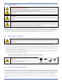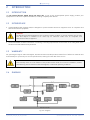
1
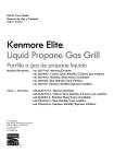
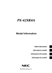
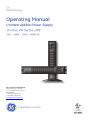
Digital Energy Operating Manual Uninterruptible Power Supply GE Consumer & Industrial SA General Electric Company CH – 6595 Riazzino (Locarno) Switzerland T +41 (0)91 / 850 51 51 F +41 (0)91 / 850 52 52 www.gepowerquality.com g imagination at work Digital Energy Model: VH Series UL Issued by: Product Document Department – Riazzino - CH Approved by R&D Department – Riazzino - CH Date of issue: 22.06.2012 File name: GE_UPS_OPM_VHU_0K7_2K0_XUL_V040 Revision: 4.0 Identification No. Up-dating Revision Concerns Date 1.0 First release 26.05.2009 2.0 Chapter 11 updated 09.01.2012 3.0 New range 700-2000 VA 27.03.2012 4.0 Updated Battery pack chapter, Power Cord specification & REPO 22.06.2012 COPYRIGHT © 2012 by GE Consumer & Industrial SA All rights reserved. The information contained in this publication is intended solely for the purposes indicated. The present publication and any other documentation supplied with the UPS system is not to be reproduced, either in part or in its entirety, without the prior written consent of GE. The illustrations and plans describing the equipment are intended as general reference only and are not necessarily complete in every detail. The content of this publication may be subject to modification without prior notice. Modifications reserved GE_UPS_OPM_VHU_0K7_2K0_XUL_V040.docx Page 2/25 Operating Manual VH Series 700 - 1000 -1500 – 2000 VA UL Digital Energy Dear Customer, We thank you for selecting our products and are pleased to count you amongst our very valued customers at GE. We trust that the use of the VH Series Uninterruptible Power Supply system, developed and produced to the highest standards of quality, will give you complete satisfaction. Please read carefully the Operating Manual, which contains all the necessary information and describes all you need to know about the use of the UPS. Thank you for choosing GE ! Distributed by: Your service contact: g GE Consumer & Industrial SA General Electric Company CH – 6595 Riazzino (Locarno) Switzerland Modifications reserved GE_UPS_OPM_VHU_0K7_2K0_XUL_V040.docx Page 3/25 Operating Manual VH Series 700 - 1000 -1500 – 2000 VA UL Digital Energy Contents 1 2 3 IMPORTANT SAFETY INSTRUCTIONS ...................................................................................................................................... 5 1.1 SAVE THESE INSTRUCTIONS ............................................................................................................................................................................. 5 1.2 SAFETY WARNINGS AND SYMBOLS .............................................................................................................................................................. 5 1.3 SAFETY RULES .......................................................................................................................................................................................................... 6 1.4 TRANSPORT / STORAGE ...................................................................................................................................................................................... 6 1.5 FCC COMPLIANCE STATEMENT ....................................................................................................................................................................... 6 INTRODUCTION ......................................................................................................................................................................... 7 2.1 INTRODUCTION ....................................................................................................................................................................................................... 7 2.2 INTENDED USE ........................................................................................................................................................................................................ 7 2.3 WARRANTY ................................................................................................................................................................................................................ 7 2.4 DIAGRAM .................................................................................................................................................................................................................... 7 INSTALLATION............................................................................................................................................................................ 8 3.1 PACKAGE CONTENTS ........................................................................................................................................................................................... 8 3.2 INSTALLATION RULES .......................................................................................................................................................................................... 8 3.3 INSTALLATION PREPARATIONS ....................................................................................................................................................................... 9 3.3.1 3.3.2 3.4 3.5 3.6 REAR PANEL ........................................................................................................................................................................................................... 11 INSTALLATION OF A BATTERY EXTENSION PACK ................................................................................................................................ 13 CONNECTIONS...................................................................................................................................................................................................... 14 3.6.1 3.6.2 4 4.3 4.4 Normal operation conditions ......................................................................................................................................................................... 16 No-load shutdown .............................................................................................................................................................................................. 16 Output frequency................................................................................................................................................................................................. 16 Switching off .......................................................................................................................................................................................................... 16 USE: STATUS AND ALARM INDICATIONS ................................................................................................................................................. 17 4.4.1 4.4.2 4.4.3 4.4.4 4.4.5 4.4.6 4.4.7 4.4.8 4.4.9 4.4.10 4.4.11 4.4.12 4.4.13 7 8 Start-up, mains available ................................................................................................................................................................................. 16 Start-up, mains not available ......................................................................................................................................................................... 16 USE: NORMAL OPERATION ............................................................................................................................................................................. 16 4.3.1 4.3.2 4.3.3 4.3.4 6 Connecting interface devices ......................................................................................................................................................................... 14 Connecting power and load ........................................................................................................................................................................... 14 OPERATION ...............................................................................................................................................................................15 4.1 OPERATING PANEL ............................................................................................................................................................................................. 15 4.2 START-UP ................................................................................................................................................................................................................ 16 4.2.1 4.2.2 5 Vertical installation - preparations ................................................................................................................................................................. 9 Rackmount installation - preparations ...................................................................................................................................................... 10 Standby .................................................................................................................................................................................................................... 18 Normal operation ................................................................................................................................................................................................ 18 On bypass ............................................................................................................................................................................................................... 18 On battery ............................................................................................................................................................................................................... 18 Battery low (end of runtime) ........................................................................................................................................................................... 18 Bypass out of limits ............................................................................................................................................................................................. 18 Overload .................................................................................................................................................................................................................. 18 Battery bad ............................................................................................................................................................................................................. 19 General alarm........................................................................................................................................................................................................ 19 Shutdown pending .............................................................................................................................................................................................. 19 Startup pending.................................................................................................................................................................................................... 19 P-N (Phase-Neutral) reversal .......................................................................................................................................................................... 19 REPO (Remote External Power Off)............................................................................................................................................................... 19 4.5 USE: SETUP MODE............................................................................................................................................................................................... 20 4.6 BATTERY MANAGEMENT .................................................................................................................................................................................. 21 COMMUNICATION ...................................................................................................................................................................22 5.1 USB PORT ................................................................................................................................................................................................................ 22 5.2 RJ11 PORT .............................................................................................................................................................................................................. 22 5.3 USB / RS232 / RELAY INTERFACE CARD (OPTION) .............................................................................................................................. 22 5.4 SNMP / WEB INTERFACE CARD (OPTION) ................................................................................................................................................ 22 MAINTENANCE .........................................................................................................................................................................23 6.1 SAFETY ...................................................................................................................................................................................................................... 23 6.2 GENERAL ................................................................................................................................................................................................................. 23 6.3 RECYCLING THE UPS AT THE END OF SERVICE LIFE .......................................................................................................................... 23 6.4 BATTERIES ............................................................................................................................................................................................................... 23 TROUBLESHOOTING................................................................................................................................................................24 SPECIFICATIONS ......................................................................................................................................................................25 Modifications reserved GE_UPS_OPM_VHU_0K7_2K0_XUL_V040.docx Page 4/25 Operating Manual VH Series 700 - 1000 -1500 – 2000 VA UL Digital Energy 1 IMPORTANT SAFETY INSTRUCTIONS 1.1 SAVE THESE INSTRUCTIONS This manual contains important instructions that should be followed during installation and maintenance of the UPS. It also gives all necessary information about the correct use of the UPS. Before attempting to install and start up the UPS, carefully read this manual. Keep this manual next to the unit for future references. Full understanding of and compliance with the safety instructions and warnings contained in this manual are the ONLY CONDITIONS to avoid any dangerous situation during installation, operation and maintenance work, and to preserve the maximum reliability of the UPS system. GE refuses any responsibility in case of non-observance, unauthorized alterations or improper use of the delivered UPS. The instructions in this manual are for UPS models VH Series 700, VH Series 1000, VH Series 1500, and VH Series 2000. Check your model number by looking at the rear panel of your UPS. Any difference in instructions is clearly indicated in the text, for instance ‘(VH Series 1000)’. The UPS is not suitable for computer room application as per the standard NFPA75. While every care has been taken to ensure the completeness and accuracy of this manual, GE accepts no responsibility or liability for any loss or damage resulting from the use of the information contained in this document. This document shall not be copied nor reproduced without the permission of GE. Due to technical improvements, some of the information contained in this manual may be changed without notice. 1.2 SAFETY WARNINGS AND SYMBOLS The text of this manual contains warnings to avoid risk to persons, to avoid damages to the UPS system and the supplied critical loads. Do not proceed beyond these warnings if you do not fully understand or are not able to meet the mentioned conditions. The non-observance of the warnings reminding hazardous situations could result in human injury and equipment damage. Please pay attention to the meaning of the following warnings and symbols. Safety warnings WARNING! Refers to procedures or operations which, when not correctly performed, could cause personal injury or serious damage to the system. CAUTION The product may be in danger: when procedures or operations are not correctly performed, damage to the product may be the result. NOTE Warns the user about important operations or procedures described in this manual. Safety Symbols DANGER OF ELECTRICALLY LIVE PARTS Related to all situations with potentially hazardous voltage. SAFETY WARNING This symbol is used for Warnings, Cautions and Notes. Modifications reserved GE_UPS_OPM_VHU_0K7_2K0_XUL_V040.docx Page 5/25 Operating Manual VH Series 700 - 1000 -1500 – 2000 VA UL Digital Energy 1.3 SAFETY RULES CAUTION! RISK OF ELECTRIC SHOCK The UPS has an internal battery supply with a nominal voltage of 72Vdc. The appliance outlets may be electrically live, even when the UPS is disconnected from the mains. The UPS contains potentially hazardous voltages. Do not open the unit, there are no user serviceable parts inside. CAUTION There may be damage to the equipment if procedures and practices are not strictly observed and followed. NOTE Do not attempt to service the UPS unless you have had proper training. Refer all maintenance and servicing to properly qualified, skilled and competent service personnel. Qualified, skilled personnel are persons who (because of their training, experience, and position as well as their knowledge of appropriate standards, regulations, health and safety requirements and working conditions) are authorised to be responsible for the safety of the equipment, at all times whilst carrying out their normal duties and are therefore aware of, and can report, possible hazards (observe IEC 60364 and national wiring regulations and accident prevention rules). 1.4 TRANSPORT / STORAGE WARNING! Please consider the weight of the UPS. Lift the box with the help of a second person; never try to lift it by yourself! No liability can be accepted for any transport damage when the equipment is shipped in non-original packaging. Store the UPS in a dry location with the batteries in a fully charged state. Storage temperature must be within -4 and 122F (-20 and +50 C). If the unit is stored for a period exceeding 3 months, optimal battery lifetime is obtained if the storage temperature does not exceed 86F (30C). If the unit is stored for an extended period of time, the batteries must be recharged periodically. Connect the unit to a wall outlet and recharge the batteries for 24 hours: - if the storage temperature is within -4 and 86F (-20 and +30°C): every 12 months, - if the storage temperature is within -4 and 122F (-20 and +50°C): every 3 months. CAUTION In case of storage, pay attention to: 1.5 FCC COMPLIANCE STATEMENT Note: This equipment has been tested and found to comply with the limits for a Class B digital device, pursuant to Part 15 of the FCC Rules. These limits are designed to provide reasonable protection against harmful interference when the equipment is operated in a residential environment. This equipment generates, uses and can radiate radio frequency energy and, if not installed and used in accordance with the instruction manual, may cause harmful interference to radio communications. Modifications not expressly approved by the manufacturer could void the user’s authority to operate the equipment under FCC rules. Modifications reserved GE_UPS_OPM_VHU_0K7_2K0_XUL_V040.docx Page 6/25 Operating Manual VH Series 700 - 1000 -1500 – 2000 VA UL Digital Energy 2 INTRODUCTION 2.1 INTRODUCTION The GE (General Electric) Digital Energy VH Series UPS, a truly on-line uninterruptible power supply, protects your equipment from all forms of power interference, including complete power failures. 2.2 INTENDED USE Uninterruptible Power Supplies (UPS) are designed to protect sensitive electronic equipment such as computers and telecommunications equipment. CAUTION DO NOT plug household appliances such as electric heaters, toasters or vacuum cleaners into the UPS. The UPS output is intended to be used only for electronic loads such as computers and telecommunications equipment. The technical data as well as information concerning connecting requirements can be found on the rating label and in this document and shall be strictly observed. 2.3 WARRANTY GE, operating through its authorised agents, warrants that the standard products will be free of defects in materials and workmanship for a period as per contract specifications, starting from the date of the invoice. NOTE This warranty does not cover failures of the product which result from incorrect installation, misuse, alterations by persons other than authorized agents, or abnormal operating conditions. 2.4 DIAGRAM Fig. 2.4: Diagram Modifications reserved GE_UPS_OPM_VHU_0K7_2K0_XUL_V040.docx Page 7/25 Operating Manual VH Series 700 - 1000 -1500 – 2000 VA UL Digital Energy 3 INSTALLATION 3.1 PACKAGE CONTENTS The UPS shipping box contains: VH Series UPS 4 plastic support parts Mounting set 1 plastic front panel 2 plastic plugs 2 mounting brackets and screws 1 USB cable 1 CD ROM with UPS monitoring software (see 5.3) and its manual This manual REPO Connector (see 4.4.13) Inspect the UPS for damage after unpacking. If any damage is present please immediately notify the carrier and place of purchase. WARNING! In case of recognizable damage: DO NOT connect any voltage to the unit DO NOT put the unit into operation Condensation may occur if the UPS system is moved directly from a cold to a warm environment. The UPS system must be absolutely dry before being installed. Please allow an acclimatization time of at least two hours. 3.2 INSTALLATION RULES NOTE Before making any connection and switching on the VH Series UPS, please check the following conditions: Your mains supply is 120 Volts and 50/60 Hz. The total power demand of the connected equipment does not exceed the rated output power of the VH Series UPS (section 8 for the ratings). The UPS is intended to be used in normal domestic and office situations. The UPS must be powered from a single phase grounded wall outlet. Do not use extension cords. Avoid locations that are excessively humid, near water, near heat sources or in direct sunlight. The ambient temperature should not exceed 104F (40C). Optimal battery lifetime is obtained if the ambient temperature does not exceed 86F (30C). It is important that ventilation air can move freely around and through the unit. Do not block the air vents. Do not plug appliances such as electric heaters, toasters and vacuum cleaners into the UPS. The UPS output can be used only for electronic loads such as computers and telecommunications equipment. Be careful when connecting laser printers: be sure that the demanded power does not exceed the capacity of the UPS. The sum of the leakage currents of the UPS and the connected loads should not exceed 3.5mA. Connect only to short circuit and over-current protection branch circuit rated in accordance with the National Electric Code, ANSI/NFPA 70, see following table: UPS model VH 700 VH 1000 Branch protection 20A 20A UPS model VH 1500 VH 2000 Branch protection 20A 20A CAUTION To reduce risk of fire, connect the UPS only to a circuit provided with fuse values according to the above Modifications reserved GE_UPS_OPM_VHU_0K7_2K0_XUL_V040.docx Page 8/25 Operating Manual VH Series 700 - 1000 -1500 – 2000 VA UL Digital Energy 3.3 INSTALLATION PREPARATIONS The UPS can be used in a stand-alone tower format using the two supporting stands (section 3.3.1), or can be mounted in a 19 inch rack using the two mounting brackets (section 3.3.2). All required items are included in the delivery. 3.3.1 Vertical installation - preparations NOTE Please consider the weight of the UPS. Lift the unit with the help of a second person. 1. Place the UPS horizontally on a table or desk. 2. Assemble the four parts of the plastic supports at the bottom-side of the UPS cabinet, using the 4 screws provided. 3. Connect the DC connector of the internal batteries. Battery block is 36V/72V and 7Ah/9Ah 1 As follows 2kVA 1.5kVA 1kVA 700VA 4. 2 3 - 6 x 9Ah, 72 V - 6 x 7Ah, 72 V - 3 x 9Ah, 36 V - 3 x 7Ah, 36 V Assemble the front panel: insert the two metal clamps at the rear of the panel into the holes at the upper side of the UPS, then click the front panel into position. Fix the front panel with the screw provided. 4 5. Place the UPS upright, and insert the two black plastic plugs to cover the holes in the top panel of the UPS cabinet. The VH Series UPS is now ready for further connections: proceed with section 3.4. 5 Fig. 3.3.1: Installation preparations - tower Modifications reserved GE_UPS_OPM_VHU_0K7_2K0_XUL_V040.docx Page 9/25 Operating Manual VH Series 700 - 1000 -1500 – 2000 VA UL Digital Energy 3.3.2 Rackmount installation - preparations NOTE Please consider the weight of the UPS prior to installation to ensure the rack is capable of supporting the weight. We recommend that the UPS is placed in its lower half. Fit the unit into the rack cabinet with the help of a second person. 1. Place the UPS horizontally on a table or desk. 2. Install the two mounting brackets that came with the unit using the screws provided. 3. Connect the DC connector of the internal batteries. 4. Assemble the front panel: insert the two metal clamps at the rear of the panel into the holes at the right side of the UPS, then click the front panel into position. Fix the front panel with the screw provided. 5. Install the UPS into a 19’ rack. The UPS cabinet must be supported by mounting rails, do not mount it by using the mounting brackets only. Fix the mounting brackets on the 19 inch enclosure with screws. 2 3 4 The VH Series UPS is now ready for further connections, please proceed with section 3.4 Fig. 3.3.2: Installation preparations - rackmount Modifications reserved GE_UPS_OPM_VHU_0K7_2K0_XUL_V040.docx Page 10/25 Operating Manual VH Series 700 - 1000 -1500 – 2000 VA UL Digital Energy 3.4 REAR PANEL The figures on this page show a VH Series 2000 VA (fig. 3.4.a) and a VH Series 1000 VA (fig. 3.4.b). The differences with the rear panel - configuration of other models is clearly indicated in the text below. 1 Input socket – max. rating 20A AC mains supply to the UPS IEC-C14 in 700-1000VA IEC-C20 in 1500-2000VA 5 2 Input thermal circuit breaker Protects the UPS from damage caused by high input currents 3 Appliance outlets - max. rating 20A To connect the loads to the UPS. Type: NEMA 5-20R 700 VA: 4 outlets 1000-2000 VA: 6 outlets 3a 4 5 8 4 Appliance outlet : max. rating 20A Type: NEMA L5-20R 2000 VA: 1outlet 3 DC connector (not on VH Series 700 VA) To connect a battery extension pack for extended battery runtime 6 3a Fan(s) Electronically controlled cooling fan(s). Make sure ventilation air can move freely around and through the UPS. 6 USB port See 5.1 for more information 7 RJ11 port 8 REPO (Remote External Power OFF) 7 1 2 Fig. 3.4.a: Rear panel VH Series 2000 VA - tower See 5.2 for more information 6 5 8 1 7 2 3 4 Fig. 3.4.b: Rear panel VH Series 1000 VA – rack mount Modifications reserved GE_UPS_OPM_VHU_0K7_2K0_XUL_V040.docx Page 11/25 Operating Manual VH Series 700 - 1000 -1500 – 2000 VA UL Digital Energy Please refer to the previous page for more information. 700VA 6 5 7 1 2 1 2 3 8 1000VA 6 5 8 7 3 4 1500VA 6 5 8 4 7 3 2 1 2000VA 6 5 8 4 3 7 3a 2 1 Fig. 3.4.c: rear panels VH Series 700 - 2000VA – rack mount orientation Modifications reserved GE_UPS_OPM_VHU_0K7_2K0_XUL_V040.docx Page 12/25 Operating Manual VH Series 700 - 1000 -1500 – 2000 VA UL Digital Energy 3.5 INSTALLATION OF A BATTERY EXTENSION PACK With a battery extension pack you can increase the battery runtime of the UPS. If you do not install a battery extension pack please skip this section and proceed with 3.6. 1. Before installation, check whether the nominal voltage of the battery pack is suitable for the UPS: the voltage mentioned on the label on the battery drawer of the UPS and the one on the rear panel of the battery extension pack (36 Vdc or 72 Vdc) should match. 2. Check if the battery breaker on the rear side of the battery pack is in the “OFF” position. 3. UPS and battery pack can be mounted together in one set of mounting supports. (For Rack mount See 3.3.2) 4. At the rear side the UPS and battery pack can be coupled using the coupling bracket that came with the battery pack. 5. Connect the DC connector of the battery pack to the DC socket of the UPS (fig. 5a and 5b). You will hear a click when the cable is properly connected. Block the DC connector: install the small locking plate that came with the battery pack, and fasten it with the screw provided. 6. Connect the DC connectors at the front side of the battery pack similar to UPS (See 3.3.1 step 3). 7. Assemble the front panel: insert the two metal clamps at the rear of the panel into the holes at the upper side of the UPS, then click the front panel into position. Fix the front panel with the screw provided. 8. Ensure that Battery Breaker at the rear side of the Battery pack is turned to “ON” Position to complete installation. Fig. 3.5: Installing battery extension pack(s) to the UPS Modifications reserved GE_UPS_OPM_VHU_0K7_2K0_XUL_V040.docx Page 13/25 Operating Manual VH Series 700 - 1000 -1500 – 2000 VA UL Digital Energy 3.6 CONNECTIONS 3.6.1 Connecting interface devices If you do not want to use the communication capabilities of the UPS, please skip this section and proceed with 3.5.2. The UPS is equipped with two interface ports: a USB port and an RJ11 port, allowing advanced communication between the UPS and a computer (network). Refer to section 5 for more detailed information. . 3.6.2 Connecting power and load NOTE The UPS output sockets can be live as soon as the UPS is connected to the main power supply, even if the UPS has not been switched on via the front panel. 1 Switch off your computer, and unplug it from the socket-outlet. 2 NOTE Grid supply is 120 Volt, 50/60 Hz, fused (see section 3.2) 2 Disconnect the power cord from the computer (see note below) and connect this cord to the male input socket (1, fig. 3.4a/b) at the rear of the UPS. 3 Add up the power consumption (in VA) of the appliances that will be protected by the UPS (‘the load’) and make sure that the resulting value does not exceed the VA output rating of the UPS. This way you ensure that the UPS is able to supply the required output and prevent that an overload situation will happen. 4. Using the output cords (see note below) connect the load to the appliance outlets (3, fig. 3.4a/b) of the unit. Spread the loads over the appliance outlets as equally as possible. If you use a distribution box to connect more than one appliance per outlet, please note that the maximum AC-current rating of each appliance outlet is 20A (3, outlets on fig. 3.4a/b). 5 Connect the mains cord of the UPS to a working, grounded AC wall socket outlet. The green LED ‘operation’ will blink now: mains power is available and the batteries are charging. If the LED does not blink but illuminates continuously instead, press keypad ‘0’ for one second. If both LEDs ‘operation’ and ‘alarm’ blink and the beeper sounds 1/2secs, phase and neutral are reversed at the input of the UPS. Please read 4.4.12 and take appropriate measures. For best results, allow the UPS to recharge the batteries during a period of approx. 2 hours. It is acceptable to use the UPS without first charging the battery, but the runtime may be reduced. 4 5 Fig. 3.5.2: Connecting power and load NOTE: To connect UPS and loads use Cables meeting the below requirements: Detachable UL Listed, SJT Type flexible cord with grounding type plug, maximum 14.76 ft. (4.5m) long. Cord type and ratings as per the table below: UPS Model AC Power Cord Rating (Minimum) VH700 UL VH1000 UL 125V / 10A VH1500 UL 125V / 15A VH2000 UL 125V / 20A Modifications reserved GE_UPS_OPM_VHU_0K7_2K0_XUL_V040.docx Plug Type NEMA (L)5-15P or NEMA (L)5-20P NEMA (L)5-15P or NEMA (L)5-20P NEMA (L)5-20P Connector Type UPS Outlet IEC C13 NEMA 5-20R IEC C19 NEMA 5-20R IEC C19 NEMA 5-20R and NEMA L5-20R Page 14/25 Operating Manual VH Series 700 - 1000 -1500 – 2000 VA UL Digital Energy 4 OPERATION 4.1 OPERATING PANEL 1 3 4 5 6 2 7 8 Fig. 4.1: Operating panel switch / LED main function 1- ‘on’ switch switches on the UPS, starts quick battery test (see 4.6) 2- ‘off’ switch switches off the UPS 3- LED ‘operation’ on when the UPS is operating blinks if the UPS is in standby mode 4- LED ‘on bypass’ on when the UPS operates in bypass mode: the incoming mains power is channeled directly to the load 5- LED ‘on battery’ on in case of battery operation: the mains power fails, and the internal batteries supply the required power until either they are depleted or mains power returns. 6- LED ‘alarm’ blinks in case of an alarm 7- LED bar ‘runtime capacity’ the remaining available battery runtime for the actual load, in % of the maximum runtime with the actual load 8- LED bar ‘load’ indicates to what extent the output capacity of the UPS is used by the actual load. If e.g. the 25% and 50% LED are on, the load exceeds 50% of the maximum load. If all 4 LEDs are on the unit operates in overload. As this is an abnormal situation the alarm LED will blink as well. More info in section 4.3.2. Modifications reserved GE_UPS_OPM_VHU_0K7_2K0_XUL_V040.docx Page 15/25 Operating Manual VH Series 700 - 1000 -1500 – 2000 VA UL Digital Energy 4.2 START-UP 4.2.1 Start-up, mains available Via front panel: press keypad 'I' (1, fig. 4.1) briefly; LED ‘operation’ (already slowly blinking) will at first blink faster and after a few seconds it will illuminate continuously, indicating that the unit has started up. Via UPS monitoring software: startup after delay, see 4.4.11 for more information. The equipment connected to the UPS can now be switched on. The UPS will not start-up if "Phase Neutral reversal" indication is present (see section 4.4.12). 4.2.2 Start-up, mains not available If the mains input is absent (power cord not connected, or mains failure): Press keypad 'I' until the buzzer sounds. The LEDs ‘operation’ and ‘on battery’ will illuminate. The UPS operates on battery: it discharges the batteries. See 4.4.4 for further details about this operating mode. 4.3 USE: NORMAL OPERATION 4.3.1 Normal operation conditions the mains supply is present, the UPS is on, the load does not exceed the capacity of the UPS and the operating temperature is below alarm level 4.3.2 No-load shutdown If this function is activated, the UPS will switch off during a mains failure when the load is less than 5% of the maximum load. In this way unnecessary discharging of the batteries is avoided. The unit will automatically turn on again when mains power is restored. The default setting of the no-load shutdown function is: disabled. The setting can be changed using the UPS monitoring software. For more information please refer to the manual that came with the software. If the no-load shutdown function is activated and the load is smaller than the 5% threshold, the ‘25%’ load LED will blink to warn you that the unit will switch off during a mains failure. 4.3.3 Output frequency At power up default enabled "Auto" frequency detection updates output frequency setting by comparing it with input frequency. Only stable 50 or 60 Hz frequencies are valid, otherwise previous setting is kept (60 Hz at first start up). Setting output frequency to 50 or 60 Hz with the UPS monitoring software disables the "Auto" frequency detection. NOTE The unit can be used as a frequency converter: the input frequency range is 45-66Hz, the output frequency is selectable 50/60Hz. If the unit is used as a frequency converter, the bypass function is no longer available. As a result an audible alarm will be generated continuously (see 4.4.6). To avoid this, we advise to disable the bypass. WARNING! Changing of the output frequency can cause severe damage of equipment connected to the appliance outputs of the UPS: Be sure that the new frequency is suitable for the connected equipment! 4.3.4 Switching off Via operating panel: Press keypad ‘0’ (2, fig. 4.1) for 1 second. If the UPS is switched off the output will always be absent for a few seconds to ensure that the connected equipment is able to reboot. Using UPS monitoring software: Shutdown after delay. If electric isolation is required, unplug the power cord from the wall outlet. Modifications reserved GE_UPS_OPM_VHU_0K7_2K0_XUL_V040.docx Page 16/25 Operating Manual VH Series 700 - 1000 -1500 – 2000 VA UL Digital Energy 4.4 USE: STATUS AND ALARM INDICATIONS o status indications the operating mode ! low priority alarms abnormal operating situations !! high priority alarms situations in which the actual output voltage of the UPS is no longer guaranteed; immediate action should be taken Indicators on front panel (fig. 4.1) Situation o Standby (4.4.1) - - - o Startup pending (4.4.11) ----- o Normal operation (4.4.2) !! On bypass (4.4.3) o On battery (4.4.4) !! Battery low (4.4.5) ! Bypass out of limits (4.4.6) !! Overload (4.4.7) ! Battery bad (4.4.8) General alarm (4.4.9) o Shutdown pending (4.4.10) ----- o No-load shutdown enabled, load < 5% (4.3.2) !! Input Phase-Neutral reversed (4.4.12) ----- !! External Power Off !/!! 0-4 0-3 0-4 0-4 ----hi 0-4 0-4 ----lo ----- 25% ----- 0-4 ----hi ----- 0-4 0-4 ----lo ----- 0-4 4 ----hi ----- 0-4 0-4 ----lo ----- 0-4 0-4 ----lo / hi 0-4 0-4 ----lo ----- ----- ----- 25% --------hi ---- 0-4 0-4 ----hi Operating modes and corresponding indications, see 4.3.2 and 4.4.1 – 4.4.12. ---= intermittent = continuous 0-4 = number of LEDs that can be on, depending on runtime capacity / load 25% = LED 25% is blinking hi = 1 / 2 secs lo = 1 / 5 secs mute buzzer: press push button ‘I’ briefly Modifications reserved GE_UPS_OPM_VHU_0K7_2K0_XUL_V040.docx Page 17/25 Operating Manual VH Series 700 - 1000 -1500 – 2000 VA UL Digital Energy 4.4.1 Standby The UPS output is off, but the batteries are charging, see 3.5.2 step 5 4.4.2 Normal operation See 4.3.1. 4.4.3 On bypass The UPS is equipped with an automatic bypass switch. This switch automatically transfers the load to the mains if the UPS is unable to deliver the demanded output power due to overload or overtemperature. If all 4 load LEDs illuminate, bypass operation is caused by an overload. If only green load LEDs illuminate (the red load LED is off), bypass operation is caused by overtemperature. Take appropriate measures: reduce load and/or temperature. The UPS will switch back to normal operation when the overload has been removed or the temperature has dropped below alarm level. If a power failure occurs during bypass operation, the UPS will switch to battery operation and eventually, when the batteries are depleted, output power is lost. The bypass function can be disabled - see 4.4.6 and 4.5 for further details. Fail safe bypass operation: if the UPS becomes defective, the load may be switched to bypass (provided that the bypass function was not disabled). As the status of the UPS is unknown in this situation the indications on the operating panel may differ. 4.4.4 On battery The UPS uses the energy stored in the batteries: see section 8 ‘Batteries - runtime’. The runtime capacity LED bar will show the remaining runtime. The UPS will shutdown: after the batteries have been discharged (automatic restart), or if keypad 'O' is pressed (restart via front panel required) or if a 'UPS shutdown' command is given by the computer (automatic restart) Automatic restart depends on the setting of the ‘auto restart’ function: - if set ‘on’ the UPS will automatically restart when the mains returns - if set ‘off’ a manual restart is required, as in 4.2.1. As default the ‘auto restart’ function is ‘enabled’. The setting can be changed using the UPS monitoring software. For more information please refer to the manual that came with the software. 4.4.5 Battery low (end of runtime) If during ‘on battery’ operation the 25% LED starts blinking, the batteries are nearly discharged: the remaining runtime is less than 2 minutes (default setting, adjustable via the UPS monitoring software). Controlled shutdown of any computer equipment is absolutely necessary at this point. If the UPS operates at 100% load, the shutdown procedure should be completed within 2 minutes after the 'battery low' alarm started. If only part of the output capacity of the UPS is used this period can be longer, with aged batteries this period can be shorter. When the batteries are fully discharged, the UPS is no longer able to power the connected equipment. 4.4.6 Bypass out of limits The mains voltage or mains frequency are outside bypass input tolerance but inside UPS input tolerance (see section 8). Bypass operation is inhibited: if for whatever reason the UPS is not able to deliver the required output, output power is lost. If the input frequency is often out of tolerance – during which bypass operation is inhibited and an alarm is generated – it may be useful to disable the bypass function after which the unit operates as a UPS without automatic bypass switch. See 4.5. 4.4.7 Overload The demanded power exceeds the normal capacity of the UPS. The alarm occurs when the load is > 100%. If the load exceeds 150% the UPS will immediately switch to bypass, assuming that the conditions for a transfer to bypass are fulfilled. If an overload condition between 110-150% persists, the UPS will also switch to bypass operation. During an overload the UPS may automatically switch off within a few minutes (load dependent) and output power is lost: if a transfer to bypass is inhibited (see 4.4.6), or Modifications reserved GE_UPS_OPM_VHU_0K7_2K0_XUL_V040.docx Page 18/25 Operating Manual VH Series 700 - 1000 -1500 – 2000 VA UL Digital Energy if the bypass function has been disabled (see 4.5), or if the UPS operates on battery (see 4.4.4). To avoid these problems, be absolutely certain that the power demands of the protected equipment are within the limits of the UPS. 4.4.8 Battery bad Either the batteries are almost chemically worn out or the battery wiring, including the battery fuse, is faulty. If the batteries are aged, they must be replaced as soon as possible to ensure full protection for your equipment. Perhaps the 'battery bad' alarm occurs after a test which you started immediately after installation or after a power failure. In this case the alarm may be incorrect as the batteries have been (partly) discharged during transport or storage / during the power failure. Allow the UPS to recharge the batteries. See also 4.6. 4.4.9 General alarm ‘General alarm’ comprises a group of alarms; the buzzer behaviour indicates which alarm is active: 1 / 2 secs: General fault Overload (see 4.4.7) Overtemperature Output out of tolerance 1 / 5 secs: Charger failure Bypass out of limits (see 4.4.6) Battery bad (see 4.4.8) 4.4.10 Shutdown pending The UPS monitoring software allows you to switch the UPS into standby mode after a programmable delay time. During countdown the ‘operation’ LED will blink 2x per second and the buzzer will beep every 5 seconds. 4.4.11 Startup pending The UPS monitoring software allows you to start up UPS after a programmable delay time. During this delay time the ‘operation’ LED will blink 2x per second. 4.4.12 P-N (Phase-Neutral) reversal If the P-N reversal indication is enabled, the UPS will indicate whether the voltage between Neutral and Earth (Ground) at the UPS input exceeds a certain voltage (i.e. Phase and Neutral at the UPS input are reversed in an earthed/grounded Neutral system). In this potentially unsafe situation both LEDs ‘operation’ and ‘alarm’ will blink fast and the buzzer will sound. Reversing the mains plug will prevent this unsafe situation and will cancel the alarm. In case of non-earthed/grounded Neutral system this indication should be disabled. The default setting of the P-N reversal indication is: enabled. Changing of the setting is described in section 4.5. 4.4.13 REPO (Remote External Power Off) REPO can be used for remotely shut down the UPS by opening the cable link provided in the connector at the rear side of the UPS. The REPO functionality can be disabled by Configuration tool. (Default: Enabled) For remote connection, remove the cable link in the connector and connect to a cable with a switch. The switch should be of Normally Closed type for normal operation. When the contact is opened, UPS will shut down. Entire Front panel LEDS of the UPS will blink continuously and buzzer beeps when the UPS shut down using REPO function. To restart the UPS, the loop should be closed by either closing the remote Switch or placing the cable link in the REPO connector and the “ON” “button in the UPS front panel is pressed. WARNING! The REPO Contact is a Safety Extra Low Voltage Circuit. Connect it only to a SELV Circuit. NOTE Use standard Low Voltage Cable in accordance with National and local regulations. Modifications reserved GE_UPS_OPM_VHU_0K7_2K0_XUL_V040.docx Page 19/25 Operating Manual VH Series 700 - 1000 -1500 – 2000 VA UL Digital Energy 4.5 USE: SETUP MODE The setup mode can only be entered if the UPS is in ‘standby’ -mode: connected to a live wall outlet and switched off (LED 'operation' blinks). 1 Press keypad 'O' and keep it pressed while pressing 'I' simultaneously. Release both buttons. The setup sequence starts with the setup of the output voltage, indicated by a blinking LED ‘operation’. 2 Scroll through the four functions with keypad 'I', one of the LEDs ‘operation’, ‘on bypass’, ‘on battery’ or ‘alarm’ will blink, indicating which function has been selected (see fig 4.5). 3 Toggle the setting of the selected function by pressing switch 'O'. The LEDs on the LEDbar ‘runtime capacity’ shows the setting. 4 Store the new settings and leave the setup mode: press keypad '0' and keep it pressed while pressing 'I' simultaneously. Release both buttons. *DEFAULT SETTING fig. 4.5: Setup menu Modifications reserved GE_UPS_OPM_VHU_0K7_2K0_XUL_V040.docx Page 20/25 Operating Manual VH Series 700 - 1000 -1500 – 2000 VA UL Digital Energy 4.6 BATTERY MANAGEMENT Maximum battery life and reliability are obtained by the following features: Quick battery test The quick battery test checks whether the batteries and their wiring are healthy. If a quick battery test shows that the batteries are close to being worn out, a 'battery bad' alarm will be generated (see 4.4.8). Batteries have to be replaced as soon as possible. Automatic battery test The VH Series UPS conducts periodic automatic battery tests: 5 hours after manual switch-on 5 hours after return of mains following any power failure, and 30 days from the last battery test Manual battery test A quick battery test can be initiated manually - either via the front panel, by pressing pushbutton ‘I’ for 5 seconds during normal operation, or via UPS monitoring software. For details please refer to the manual of your software. NOTE If the test is started manually immediately after installation or after a power failure, the UPS may generate a false 'battery bad' alarm as the batteries have been (partly) discharged during transport/storage or during the power failure. Deep battery test A deep battery test, to be initiated through the UPS monitoring software, checks the actual battery capacity in order to ensure accurate runtime prediction. During a deep battery test the batteries will be discharged. NOTE When executing a deep battery test the available runtime in case of mains failure may be shorter than normal. Don’t execute this test if reduced battery runtime is not acceptable. Temperature compensated battery charging This feature adjusts the battery charge voltage according to the ambient temperature. As a result poor charging of the batteries under low temperature conditions and overcharging of the batteries under high temperature conditions are avoided. Load dependent battery-end-voltage The allowable final battery voltage depends on the discharge current: the higher the current, the lower the 'end-ofdischarge' battery voltage. In this way maximum battery capacity is obtained without over-discharging. Over-discharging would result in shortened service life and failure to recover normal capacity. Automatic boost charge This feature reduces the battery recharge time considerably: totally depleted batteries will be recharged to 90% in approx. 3.0 hours, provided that discharging took place at 100% load. Modifications reserved GE_UPS_OPM_VHU_0K7_2K0_XUL_V040.docx Page 21/25 Operating Manual VH Series 700 - 1000 -1500 – 2000 VA UL Digital Energy 5 COMMUNICATION 5.1 USB PORT The USB port is a plug-in interface port which enables advanced communication between the UPS and the computer (UPS software required). The interface port is operative as soon as the mains power cord is plugged into a live wall outlet, even if the UPS is switched off. For more information please refer to the user manual that comes with the interface software. We strongly recommend to use only original GE Digital Energy software products in combination with the interface port. NOTE The change of some settings can cause the unit to switch from bypass to standby and output power is lost. 5.2 RJ11 PORT The RJ11 port is a plug-in contact interface port. Pin # 1 2 3 4 5 6 Function Mains failure General alarm *) Battery low On bypass Remote UPS shutdown / RxD GND *) Active if the output voltage of the UPS is no longer guaranteed due to other circumstances than already indicated by pin 1-3-4. The alarms are listed in section 4.4.9. Fig. 5.2 Absolute Maximum Ratings VO IO VI MIN -0.2V Voltage applied on any output pin Output sink current Voltage applied on input pin MAX 48V 30mA 25V -25V Note: Exceeding these ratings may damage the device or anyway affect its reliability DC Characteristics CONDITION VIH VIL VOL 5.3 High-level input voltage Low-level input voltage Low (active) output voltage MIN 4.0V MAX 0.4V 0.4V Io<1mA USB / RS232 / RELAY INTERFACE CARD (OPTION) The card is equipped with • USB port as described in 5.1 • RS232 port • potential free change-over relay contacts for the following alarms: - mains failure - general alarm - battery low - bypass active For more information please refer to the user manual that comes with the interface card. 5.4 SNMP / WEB INTERFACE CARD (OPTION) The SNMP card makes the UPS ‘SNMP manageable’: it allows the data interface to be connected directly to an Ethernet network. For more information please refer to the user manual that comes with the interface card. Modifications reserved GE_UPS_OPM_VHU_0K7_2K0_XUL_V040.docx Page 22/25 Operating Manual VH Series 700 - 1000 -1500 – 2000 VA UL Digital Energy 6 MAINTENANCE 6.1 SAFETY DANGER When the UPS operates, all parts of the electronics are directly connected to the utility and high voltages are present on all internal parts, including the battery. Even after disconnection from the utility, all parts inside the UPS, including the battery, conduct dangerous voltages (except the RJ11 and USB output). For your safety, only authorized service personnel may remove the cabinet cover. Refer to section 1.2 for further details. 6.2 GENERAL The GE Digital Energy VH Series UPS is virtually maintenance free: take care of proper environmental conditions and keep air inlets/outlets free of dust. Please read 3.2. NOTE Leave maintenance and service work to qualified and skilled personnel only. Refer to section 1.2 for further details. 6.3 RECYCLING THE UPS AT THE END OF SERVICE LIFE NOTE This product has been designed to respect the environment, using materials and components respecting eco-design rules. It does not contain CFCs (Carbon Fluorine Chloride) or HCFCs (Halogen Carbon Fluorine Chloride). The batteries contain lead, which is a harmful substance for the environment. Proper disposal or recycling of the batteries is required. Refer to your local codes for disposal requirements. Don’t throw batteries away, treat them as harmful waste. GE Consumer & Industrial, in compliance with environment protection recommends that the UPS equipment, at the end of its service life, must be recycled conforming to the local applicable regulations. 6.4 BATTERIES The service life of the battery is from 3 to 6 years, depending on the operating temperature and on the number of discharge cycles. As a healthy battery is critical to the performance of the UPS, an automatic quick battery test is performed regularly to ensure failsafe operation (see section 4.6). When the condition of the battery is critical, a 'battery bad' alarm will be activated (see 4.4.8). Replace the batteries as soon as possible. NOTE Under certain circumstances a manual battery test can result in a false alarm: please see 4.6 'quick battery test'. Modifications reserved GE_UPS_OPM_VHU_0K7_2K0_XUL_V040.docx Page 23/25 Operating Manual VH Series 700 - 1000 -1500 – 2000 VA UL Digital Energy 7 TROUBLESHOOTING Whenever a malfunction occurs, first check external factors (e.g. connections, temperature, humidity or load) to determine whether the problem is caused by the unit itself or by its environment. Subsequently check the thermal circuit breaker: it may be tripped. If so: reset it (see fig. 3.4a/b) and be sure that the UPS is not overloaded. The following chart is a simple troubleshooting checklist only. If the suggested solution does not succeed, or if the information is insufficient to solve the problem, please contact your dealer or consult www.gedigitalenergy.com. PROBLEM POSSIBLE CAUSE SOLUTION UPS overload Reduce load, reset TCB (2, fig. 3.4a/b) System failure Contact your dealer or consult www.gedigitalenergy.com Thermal Circuit Breaker (TCB) tripped Line cord not connected UPS will not switch on (without using 'battery start') and the output has been off for a few secs. (see also 4.3.4) LEDs ‘operation’ and ‘alarm’ blink, buzzer sounds 1/2 secs. UPS does not start. Read 3.5.2 Connect line cord Dead wall socket outlet, or mains voltage out of limits Contact qualified electrician Tripped Thermal Circuit Breaker See above P (phase) and N (neutral) are reversed at the UPS input in a system with grounded Neutral. In a system with grounded Neutral: reverse the mains plug. In other systems: disable the indication. See 4.4.12 and 4.5. In case of doubt contact a qualified electrician. UPS overtemperature Allow UPS to cool down Mains failure, battery discharged Wait until mains returns Programmed shutdown in progress See 4.4.10 The load is < 5% of the max. load and no mains power is present. (No-load shutdown function is active, see 4.3.2) Wait until mains returns Battery test just after installation or mains failure Allow the UPS to recharge the batteries Battery test shows weak battery Have the batteries replaced UPS switched off automatically LEDs ‘alarm’ and ‘on battery’ blink, buzzer sounds 1/5 secs Modifications reserved GE_UPS_OPM_VHU_0K7_2K0_XUL_V040.docx Page 24/25 Operating Manual VH Series 700 - 1000 -1500 – 2000 VA UL Digital Energy 8 SPECIFICATIONS VH Series : 700 1000 1500 2000 Ratings Voltage Amperes (VA) with computer type load Watts (W) with resistive load Input thermal circuit breaker (A) Internal input fuse 250V, slow (A) : : : : 700 630 8 15 1000 900 12 15 1500 1350 18 30 1920 1740 20 30 Input converter AC input voltage Input current waveform Input current (A) at nominal input voltage Input power factor Input frequency range Inrush current : : : : : : 60 - 140 V sinusoidal, EN 61000-3-2 (IEC 555-2) compliant 6.6 9.1 1 45 - 66 Hz none 13.9 16 Output converter AC output voltage AC output voltage tolerance Output frequency Output frequency range Output waveform Harmonic distortion Power factor Crest factor (peak to RMS current) Capacity appliance outlets : : : : : : : : : 100 / 110 / 115/120/127 V (selectable) ± 2% auto selectable or 50 / 60 Hz, front selectable nominal ± 0.05% sine wave < 1% with linear load 0.9 suitable for loads with c.f. up to 3:1 max. 20A per outlet (+ 1 high power outlet max. 20A, on 2000VA model only) Bypass AC input voltage range Frequency tracking rate Frequency tracking range Phase difference Typical transfer time, msec : : : : : selected output voltage -15% to +10% 2 Hz/sec. nominal ± 10% / ± 2% selectable < 1º typical (max. 7º during tracking frequency range) 1 : : : : fully protected against overload and short circuits 110% 4 minutes 150% 2 seconds depends on rating of thermal circuit breaker typical: 125% of TCB value for 200 seconds 200% of TCB value for 10 seconds 300% of TCB value for 4 seconds : : : : : 36 36 3/7 3/9 sealed lead acid, maintenance free up to 6 years (depending on use) 1.5 A : : 3 hours for 90% capacity, std battery 12 12 : : : : : : 22 12 8 : : : : 35/16 Overload capability Overload behaviour during battery operation Overload behavior during bypass operation Batteries (ratings given for 77ºF Nominal voltage (Vdc) Number / Ah batteries Type Service life Recharge current Battery recharge time (batt. discharged at 100% load) Runtime in minutes at typical load (75%) VA/Watts 250/225 500/450 700/630 1000/900 1500/1350 1920/1740 General Weight UPS (lbs/kg) Dimensions UPS (HxWxD) Enclosure / protection Battery pack Nominal Voltage (Vdc) Nominal Capacity (Ah) Weight (lbs/kg) Dimensions (HxWxD) Environment Safety Electromagnetic compatibility Ambient temperature Audible noise at 1 meter Max. relative humidity Modifications reserved GE_UPS_OPM_VHU_0K7_2K0_XUL_V040.docx : : : : : : : : : : 72 6/7 72 6/9 11 12 35 18 12 8 58 28 21 13 7 70 36 27 20 12 8 37/17 64/29 3.4x17.2x18.5inch 87x438x470 mm steel-plastic / IP20 71/32 3.4x17.2x21.3 inch 87x438x540 mm 36 72 60/27 3.4x17.2x18.5inch 87x438x470 mm 101/46 3.4x17.2x21.3 inch 87x438x540 mm 14 UL 1778, 4th Edition EN 62040-2 32 to 104ºF (0 to +40ºC) < 45 dB(A), load and temperature dependent 95% (non-condensing) Page 25/25 Operating Manual VH Series 700 - 1000 -1500 – 2000 VA UL