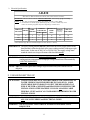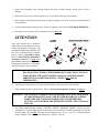
1
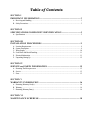
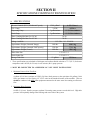
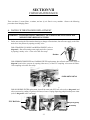
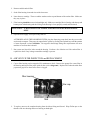
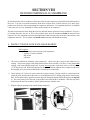
AD-830
Installation Manual
For replacement parts, contact the reseller from which the machine
was purchased or
American Dispensing Company
88 Currant Road
Fall River MA 02720-4781
Telephone: (508) 678-9000 / Fax: (508) 678-9447
E-mail: [email protected]
081696OC
ADC Part No. 182714
Retain This Manual In A Safe Place For Future Reference
American Dispensing Company products embody advanced concepts in engineering, design, and safety. If
this product is properly maintained, it will provide many years of safe, efficient, and trouble-free operation.
ONLY properly licensed technicians should service this equipment.
OBSERVE ALL SAFETY PRECAUTIONS displayed on the equipment or specified in the installation manual
included with the water vending machine.
WARNING: UNDER NO CIRCUMSTANCES should the pressure switch(es) or other safety
devices ever be disabled.
We have tried to make this manual as complete as possible and hope you will find it useful. ADC reserves the
right to make changes from time to time, without notice or obligation, in prices, specifications, colors, and material,
and to change or discontinue models.
Important
For your convenience, log the following information:
DATE OF PURCHASE ____________________________
MODEL NO.
AD-830
__________________________________________
RESELLER’S NAME _______________________________________________________________________________________
Serial Number(s)
________________________________________________________________________________________
________________________________________________________________________________________
________________________________________________________________________________________
Replacement parts can be obtained from your reseller or the ADC factory. When ordering replacement parts
from the factory, you can FAX your order to ADC at (508) 678-9447 or telephone your order directly to the ADC
Parts Departmentat (508) 678-9000. Please specify the water vending machine model number and serial
number in addition to the description and part number, so that your order is processed accurately and promptly.
The illustrations on the following pages may not depict your particular water vending machine exactly. The
illustrations are a composite of the various water vending machine models. Be sure to check the descriptions of
the parts thoroughly before ordering.
IMPORTANT
YOU MUST DISCONNECT and LOCKOUT THE ELECTRIC
SUPPLY BEFORE ANY COVERS or GUARDS ARE REMOVED FROM
THE MACHINE TO ALLOW ACCESS FOR CLEANING, ADJUSTING,
INSTALLATION, or TESTING OF ANY EQUIPMENT per OSHA
(Occupational Safety and Health Administration) STANDARDS.
CAUTION
LABEL ALL WIRES PRIOR TO DISCONNECTION WHEN SERVICING
MACHINE. WIRING ERRORS CAN CAUSE IMPROPER and DANGEROUS
OPERATION.
FOR YOUR SAFETY
THE SYSTEM IS SHIPPED WITH A PRESERVATIVE SOLUTION MADE
OF SODIUM BISULFITE (IN THE WINTER MONTHS) GLYCERINE. MAKE
SURE THE SYSTEM IS THOROUGHLY PURGED BEFORE LETTING ANYONE
DRINK THE DISPENSED WATER.
REFER TO THE INSTALLATION SECTION ON PURGING PROCEDURE.
CAUTION
Never look directly into the unprotected parts of the U.V. chamber when there is
power to the sterilizer. Serious burns to the eyes and skin may result. Always unplug
power to the sterilizer before working on it.
IMPORTANT
Please observe ALL safety precautions displayed on the equipment and specified
in this manual.
IMPORTANT
The wiring diagram for the water vending machine is located on the inside right
wall of the machine.
Water vending machines must not be installed or stored in an area where it will
be exposed to water or weather.
Table of Contents
SECTION I
IMPORTANT INFORMATION ............................................................................... 3
A. Receiving and Handling ............................................................................................................... 3
B. Safety Precautions ...................................................................................................................... 3
SECTION II
SPECIFICATIONS/COMPONENT IDENTIFICATION .................................... 5
A. Specifications ............................................................................................................................. 5
SECTION III
INSTALLATION PROCEDURES ........................................................................... 9
A.
B.
C.
D.
E.
F.
Location Requirements ............................................................................................................... 9
System Description ..................................................................................................................... 9
Water Supply ........................................................................................................................... 10
Feed Water and Drain Plumbing ................................................................................................ 11
Electrical Information ................................................................................................................ 11
Unpacking/Setting Up ............................................................................................................... 12
SECTION IV
SERVICE and PARTS INFORMATION .............................................................. 15
A. Resetting The Microprocessor .................................................................................................. 15
B. Service ..................................................................................................................................... 15
C. Parts ........................................................................................................................................ 15
SECTION V
WARRANTY INFORMATION .............................................................................. 16
A. Returning Warranty Card(s) ...................................................................................................... 16
B. Warranty .................................................................................................................................. 16
C. Returning Warranty Part(s) ........................................................................................................ 16
SECTION VI
MAINTENANCE SCHEDULE............................................................................... 18
SECTION VII
FILTER MAINTENANCE ...................................................................................... 22
A. Water Filter/Strainer Replacement ............................................................................................. 22
B. Air Filter Inspection and Replacement ....................................................................................... 23
SECTION VIII
REVERSE OSMOSIS (R.O.) MEMBRANE ........................................................ 24
A. Product Water Flow Rate Measurement .................................................................................... 24
B. Membrane Cleaning .................................................................................................................. 27
C. Storage and Shipping of Membrane .......................................................................................... 30
SECTION IX
ULTRAVIOLET (U.V.) STERILIZER .................................................................... 32
A. Ultraviolet (U.V.) Lamp Replacemet Procedure ......................................................................... 32
B. Quartz Sleeve and Cleaning Procedure ...................................................................................... 33
C. Ultraviolet (U.V.) Probe Cleaning Procedure ............................................................................. 34
SECTION X
MISCELLANEOUS MAINTENANCE TECHNIQUES ..................................... 35
A. Drain Bay Cleaning ................................................................................................................... 35
B. Vending Nozzle Adjustment ....................................................................................................... 36
C. Tubing and Fitting Replacement Technique ................................................................................. 36
SECTION XI
TROUBLESHOOTING ........................................................................................... 38
SECTION I
IMPORTANT INFORMATION
A. RECEIVING and HANDLING
The water vending machine is shipped in a protective stretch wrap cover with protective cardboard corners and
top cover (or optional box) as a means of preventing damage in transit. Upon delivery, the water vending
machine, packaging material, and wooden skid should be visually inspected for shipping damage. If any damage
is noticed, inspect further before delivering carrier leaves.
Water vending machines damaged in shipment:
1. ALL water machines should be inspected upon receipt and before they are signed for.
2. If there is suspected damage or actual damage, the trucker’s receipt should be so noted.
3. If the water vending machine is damaged beyond repair, it should be refused. Those water vending
machines, which were not damaged in a shipment should be accepted, but the number received and the
number refused must be noted on the receipt.
4. If you determine that the water vending machine was damaged after the trucker has left your location, you
should call the delivering carrier’s freight terminal immediately and file a claim. The freight company
considers this concealed damage. This type of freight claim is very difficult to get paid and becomes
extremely difficult when more than a day or two passes after the freight was delivered. It is your responsibility
to file freight claims. Water vending machines and parts damaged in transit cannot be claimed under
warranty.
5. Freight claims are the responsibility of the consignee, and claims must be filed at the receiving end. ADC
assumes no responsibility for freight claims or damages.
6. If you need assistance in handling the situation, please contact the ADC Traffic Manager at (508)
678-9000.
IMPORTANT: The water vending machine must be transported and handled in an upright position at
ALL times.
B. SAFETY PRECAUTIONS
IMPORTANT: Refer to this manual before making any repairs or adjustments, or doing any
maintenance on this machine.
IMPORTANT: For owners who DO NOT personally maintain the machine, it is their responsibility
that the operator has been properly instructed and is fully aware of the manual
contents. This is important in the safe handling and efficient operation of the machine.
3
IMPORTANT: Follow maintenance schedule rigorously. Careless maintenance may lead to
component failure and increase operating costs significantly.
CAUTION: DO NOT make any alteration or modification in the wiring or plumbing of this machine.
Such alterations may result in injury, illness, or death to maintenance personnel, operators,
or users of this machine.
WARNING: DO NOT allow machine to freeze. Freezing will irreparably damage components in the
machine.
NOTE: NEVER LOOK DIRECTLY INTO THE UNPROTECTED PARTS OF THE U.V.
CHAMBER WHEN THERE IS POWER TO THE STERILIZER. SERIOUS
BURNS TO THE EYES and SKIN MAY RESULT. ALWAYS UNPLUG POWER TO
THE STERILIZER BEFORE WORKING ON IT.
NOTE: THE SYSTEM IS SHIPPED WITH A PRESERVATIVE SOLUTION MADE OF
SODIUM BISULFITE and (IN THE WINTER MONTHS) GLYCERINE. MAKE
SURE THE SYSTEM IS THOROUGHLY PURGED BEFORE LETTING ANYONE
DRINK THE DISPENSED WATER. SEE SECTION III ON INSTALLATION
PROCEDURES.
DISCLAIMER
The information contained in this document is subject to change without notice.
American Dispensing Company shall not be liable for technical or editorial omissions made herein; nor incidental
or consequential damages resulting from the furnishing, performance, or use of this material.
4
SECTION II
SPECIFICATIONS/COMPONENT IDENTIFICATION
A. SPECIFICATIONS
Reverse Osmosis (R.O.) MembraneCapacity
1,200 gallons*
4.542.2 liters*
3/4 HP
0.55 kw
Dispensing Pump
3 gallon/minute
11.36 liters/minute
Drain Pump
3 gallon/minute
11.36 liters/minute
R.O. Pump
Water Vending Machines Per 20'/40
10/20
Water Vending Machines Per 45'/48
24/26
Voltage Available
115-240v 1Ø 50/60 Hz
Approximate Weight (Uncrated Empty)
1100 lbs.
498.9 kg
Approximate Weight (Uncrated Full/Capacity)
1700 lbs.
771.1 kg
Approximate Weight (Crated)
1200 lbs.
544.3 kg
Water Inlet Size
1/2 N.P.T. **
Drain Outlet Size
1/2 N.P.T. **
Storage Tank Size
93 gallons
352 liters
* These specifications are calculated at 2,000 ppm, total sodium chloride solution at 77º F (25º C) feed water
temperature and 160 PSI (11.03 bars) reverse osmosis (R.O.) pump pressure.
** MUST BE CONNECTED TO A MINIMUM 3/4” N.P.T. INLET WATER SUPPLY.
1. Minimum Pressure Inlet Flow Rate
4 gallons (15.14 liters) a minute at 35 PSI. (2.41 bars) back pressure or the equivalent of 9 gallons (34.06
liters) per minute at a free flowing 1/2” N.P.T. outlet at the intended location of the machine. This test
should be conducted with ALL other equipment connected to the same water line running to reflect true
flow.
2. Maximum Water Pressure
80 PSI. (5.51 bars). Install a pressure regulator if incoming water pressure exceeds this level. High inlet
pressure will irreparably damage filter housings and cause leaks in the system.
5
6
B. COMPONENT IDENTIFICATION
7
VENDING SOLENOIDS
INLET VALVE
PROGRAMMING SWITCH
DISPLAYS
R.O. PRESSURE REGULATOR
TRAP DOORS
INLET SOLENOID
EXPANSION TANK
COMPUTER
DOUBLE CHECK VALVE
LOW PRESSURE SWITCH
REAR ELECTRICAL
TEST CELL
HIGH PRESSURE SWITCH
TRA VIOLET STERILIZE
CARBON FILTER
SEDIMENT FILTER
R.O. FILTER
POLISHING FILTER
8
SECTION III
INSTALLATION PROCEDURES
Installation should be performed by competent technicians in accordance with local and state codes. In the
absence of these codes, the installation must conform to applicable American National Standards: ANSIZ223.1LATEST EDITION (National Fuel Gas Code) or ANSI/NFPA NO. 70-LATEST EDITION (National Electrical
Code) or in Canada, the installation must confirm to applicable Canadian Standards: CAN/CGA-B149.1-M91
(Natural Gas) or CAN/CGA-B149.2-M91 (Liquid Propane [L.P.] Gas) or LATEST EDITION (for General
Installation and Gas Plumbing) or Canadian Electrical Codes Parts 1 & 2 CSA C22.1-1990 or LATEST EDITION
(for Electrical Connections).
A. LOCATION REQUIREMENTS
WARNING: Feed water must come from inspected, approved water system only. Source must be
microbiologically safe drinking water.
1. The water vending machine must be installed on a sound level floor capable of supporting its weight. It is
recommended that carpeting be removed from the floor that the water vending machine is to rest on.
2. The water vending machine must not be installed or stored in an area where it will be exposed to water and
weather.
3. Provisions for adequate water supply must be provided as noted in this manual. (Refer to Water Supply
in Section C).
4. Plumbing should be performed in accordance to local, state and federal codes. (Refer to Feed Water and
Drain Plumbing in Section D).
5. Provisions must be made for adequate clearances for servicing and for operation as noted in this manual.
(Refer to Enclosure Requirements in Section II).
B. SYSTEM DESCRIPTION
Thank you for purchasing the model AD-840 water vending machine. It is made by American Dispensing
Company and is one (1) of the most advanced water vending machines on the market today. It is microprocessorbased and programmable. It interacts with the customer and owner through a light emitting diode (L.E.D.)
display and a membrane keyboard (touch pad). The AD-830 purifies water through a five-step process:
Incoming water first passes through a 10-micron absolute SEDIMENT FILTER. This means that suspended
solids larger than 0.01 mm (or about forty-thousands of 1-inch) such as slit and fine sand are removed.
Water then passes through a CARBON FILTER. This removes chlorine, odor, and a variety of organic
contaminants, such as chloroform and pesticide residue. The AD-830 uses a carbon filter with an extruded
carbon core and an inner filtration wrap. This combination ensures that, unlike a conventional granular activated
carbon (G.A.C.) filter, there is no channeling or bypassing, and no release of fine carbon particles.
9
Water is then pumped through a thin film composite reverse osmosis (R.O.) membrane at about 160 PSI (11.03
bars). The R.O. membrane removes over ninety percent (90%) of a variety of salts and inorganic materials
found in water, such as dissolved salts of sodium, lead, nitrate; it removes typically over ninety-nine percent
(99%) of radioactivity, like radon. Actual rejection rate will depend on feed water chemistry, temperature, and its
total dissolved solid content.
Water is then stored in an atmospheric water tank, sealed except for an air vent, which is protected from dust and
airborne bacteria by a submicron air filter.
When your customer selects a vend, water will be pumped through a combination sediment/carbon POLISHING
FILTER which removes any remaining taste and sediment, and an ULTRAVIOLET (U.V.) STERILIZER which
sterilizes the water.
To keep the stored water fresh and sterilized, the water in the storage tank is recirculated through the polishing
filter and the U.V. sterilizer periodically.
Safety is our prime concern and it is designed into the machine. At the inlet and outlet of the R.O. membrane, a
comparator reads the total dissolved solid rejection rate, an indicator of the performance of the membrane. If the
rejection rate falls below a certain level, the microprocessor will shut the machine down. The same logic applies
to the U.V. sterilizer, where a true U.V. sensor continually monitors the disinfecting power of the light and shuts
down the machine when the U.V. level is not high enough.
There is also overflow and leakage protection. The sensors are located on the base of the machine, in the drain
tank of the dispensing bay and in the water storage tank. These sensors detect overflow or leakage and will shut
off whatever components are necessary.
NOTE: The machine is approved by the NATIONAL AUTOMATIC MERCHANDISING
ASSOCIATION (NAMA) in Chicago. In many states, this is a requirement for water
vending machine installation.
C. WATER SUPPLY
The following conditions are required for optimum performance:
WARNING: FEED WATER MUST COME FROM INSPECTED, APPROVED WATER
SYSTEMS ONLY. SOURCE MUST BE MICROBIOLOGICALLY SAFE
DRINKING WATER.
1. Minimum Pressure/Inlet Flow Rate
4 gallons (15.14 liters) a minute at 35 PSI (2.41 bars) back pressure or the equivalent of 9 gallons (34.06
liters) per minute at a free flowing 1/2” N.P.T. outlet at the intended location of the machine. This test
should be conducted with ALL other equipment connected to the same water line running to reflect true
flow.
2. Maximum Water Pressure
The maximum water pressure is 80 PSI (5.51 bars). Install a pressure regulator if incoming water pressure
may exceed this level. High inlet pressure will irreparably damage filter housing and cause leaks in the
system.
10
3. Temperature
This machine should be kept in an environment between 40° F and 108º F (4.44° and 42.22°). Exposing the
machine to freezing temperatures will irreparably damage the components.
4. Mineral Content
Pretreatment of incoming water is recommended if hardness exceeds 150 ppm or 9 grains per gallon, or if
iron levels exceed 0.05 ppm. Membrane will still function with high mineral content water, but yield will drop
substantially, membrane cleaning is required more frequently, and membrane life will be shortened significantly,
increasing overall operating costs.
D. FEED WATER and DRAIN PLUMBING
1. Inlet and outlet of the machine are 1/2” N.P.T., female threads. Use for connection only sanitary plumbing
materials appropriate for drinking water.
NOTE: Minimum 3/4” N.P.T. inlet water supply.
2. Drain outlet should have a minimum of a 2-inch (5.08 cm) air gap at the point of discharge. Follow ALL
applicable plumbing codes when making connections.
E. ELECTRICAL INFORMATION
1. Electrical Requirements
It is your responsibility to have ALL electrical connections made by a properly licensed and competent
electrician to assure that the electrical installation is adequate and conforms to local and state regulations or
codes. In absence of such codes, ALL electrical connections, material, and workmanship must conform
to the applicable requirements of the National Electrical Code ANSI/NFPA NO. 70-LATEST EDITION or
in Canada, the Canadian Electrical Codes Parts 1 & 2 CSA C22.1-1990 or LATEST EDITION.
IMPORTANT: Failure to comply with these codes or ordinances and requirements stipulated in this
manual can result in personal injury or component failure.
NOTE: Component failure due to improper installation will VOID THE WARRANTY.
Each water vending machine should be connected to an independently protected branch circuit. The
water vending machine must be connected with copper wire only. DO NOT use aluminum wire, which
could cause a fire hazard. The copper conductor wire or cable must be of proper ampacity and insulation
in accordance with electric codes for making ALL service connections.
NOTE: The use of aluminum wire will VOID THE WARRANTY.
11
2. Electrical Specifications
AD-830
ELECTRICAL SERVICE SPECIFICATIONS (PER WATER VENDING MACHINE)
IMPORTANT: 208 VAC and 230/ 240 VAC ARE NOT THE SAME. When ordering, specify exact voltage.
NOTES: A. Fuse ratings are dual element time delay current limiting, class RK1 or RK5 ONLY.
B. Circuit breakers are thermal magnetic (industrial) type only. For others, calculate/verify correct
breaker size according to appliance amp draw rating and type of breaker used.
SERVICE
WIRE
PHASE
VOLTAGE
SERVICE
APPROX.
AMP DRAW
50 Hz
60 Hz
MINIMUM
WIRE
SIZE*
FUSING
Dual Element
Time Delay
CIRCUIT
BREAKER
115
1ø
2
15
14
12
25
30
208
1ø
2
8
7
14
12
15
230/240
1ø
2
8
7
14
12
15
* AWG Stranded Type Wire for individual lengths less than 100 feet (31 meters).
IMPORTANT: The water vending machine must be connected to the electric supply shown on the
data label that is affixed to the back of the water vending machine, at the upper right
hand corner. In the case of 208 VAC or 230/240 VAC, the supply voltage must
match the electric service specifications of the data label exactly.
WARNING: 208 VAC and 230/240 VAC ARE NOT THE SAME. Any damage done to water
vending machine components due to improper voltage connections will automatically
VOID THE WARRANTY.
NOTE: ADC reserves the right to make changes in specifications at any time without notice or
obligation.
F. UNPACKING/SETTING UP
ATTENTION: CHECK STATE and LOCAL LAWS REGARDING THE OPERATION OF
WATER VENDING MACHINES BEFORE INSTALLATION. SOME
STATES REQUIRE VENDORS TO NOTIFY THE DEPARTMENT OF
PUBLIC HEALTH or WEIGHTS and MEASURES CONCERNING THE
INSTALLATION OF THE MACHINE. FOLLOW ALL APPLICABLE
FEDERAL, STATE and LOCAL STANDARDS FOR DRINKING WATER
INSTALLATIONS.
ATTENTION: BE SURE THE INSTALLATION OF THIS MACHINE COMPLIES WITH
ALL LOCAL PLUMBING and ELECTRICAL CODES.
WARNING: DO NOT CONNECT ELECTRICAL POWER TO MACHINE UNTIL
REQUESTED.
12
1. Remove the wrappings of the vending machine and check for transit damage. Notify carrier if there is
damage.
2. Skid can be removed by unscrewing four (4) 5/16” skid bolts at the legs of the machine.
3. Place machine at the intended location and, if required, adjust the 3/4” bolts at the legs until the machine is
level and stable.
4. Connect plumbing inlet and outlet lines. Refer to guidelines in the section “SITE REQUIREMENTS.”
5. Reconnect reverse osmosis (R.O.) membrane (refer to page 13).
ATTENTION
The reverse osmosis (R.O.) membrane
in this machine is filled with a preservative
solution and plugged for shipping. The
two lengths of tubing illustrated below will
have to be reconnected before machine
start-up. (Refer to diagrams to right).
Refer to “Miscellaneous Maintenance
Technique, Section C” on page 35 of
the installation manual for tubing removal
and attachment technique. Push tubing
into fittings firmly to prevent leakage.
CAUTION: WEAR PROTECTIVE CLOTHING, GLOVES, and SAFETY GLASSES WHEN
RECONNECTING TUBING. THE PRESERVATIVE SOLUTION CONTAINS
SODIUM BISULFITE and GLYCERINE and MAY CAUSE SKIN and EYE
IRRITATION IN SOME INDIVIDUALS. WIPE UP ALL SPILLS
IMMEDIATELY.
6. Open the main water ball valve located inside the cabinet at the water inlet of the machine.
7. Plug machine into the electrical outlet. (Refer to Electrical Information, Section E on page 11).
WARNING: THE MACHINE IS SHIPPED WITH A PRESERVATIVE SOLUTION MADE
OF SODIUM BISULFITE and (IN THE WINTER MONTHS) GLYCERINE.
MAKE SURE THE SYSTEM IS THOROUGHLY PURGED BEFORE
LETTING ANYONE DRINK THE DISPENSED WATER. (SEE STEP #9 and
STEP #10).
8. The display should blink the message: “SYSTEM” “PURGE” “DO NOT” “DRINK.” Purge cycle starts
automatically. Clear the dispensing bay of obstacles, as water will come out of the dispensing valve and into
the drain basin. Discard ALL water dispensed until purge cycle is over. Cycle is over when the display
blinks “INSERT” and “COIN” or the amount for 1 gallon (3.78 liters).
13
Several minutes into the purge cycle, check the following:
a. Pressure gauge at the reverse osmosis (R.O.) pump on the base of the
cabinet should read between 140 and 180 PSI (9.65 and 12.41 bars)
with the pump running (refer to diagram 1). If it is not within range,
adjust back pressure valve to return reading to 160 PSI (11.03 bars).
Back pressure valve is located near the drain outlet. Unscrew cap and
loosen locknut. Turn adjusting bolt into valve for higher back pressure
and vice versa. Tighten locknut and replace cap.
DIAGRAM 1
b. Visually note any leaks in the system. When the dispensing valve opens again during purge cycle, check
for leaks on the dispensing side at this time.
9. Take a sample of the dispensed water after the purge cycle is over. Smell the water to ensure no odor is
present. If there is, dispense water until water is free of odor.
10. The water is ready for vending.
ATTENTION: MEASURE THE INITIAL FLOW RATE OF THE PRODUCT WATER
FROM THE R.O. MEMBRANE WITHIN 24 TO 48 HOURS OF NEW
MACHINE OPERATION. REFER TO REVERSE OSMOSIS (R.O.)
MEMBRANE IN SECTION VIII, FOR PROCEDURE. THIS IS
IMPORTANT AS IT DETERMINES WHEN MEMBRANE NEEDS TO BE
CLEANED IN THE FUTURE.
ATTENTION: TO REDUCE BIOFOULING, IT IS RECOMMENDED THAT A
MINIMUM OF 12 GALLONS (45.42 LITERS) BE VENDED EVERY 72
HOURS. THE LESS THE IDLE TIME BETWEEN VENDS, THE LESS
LIKELY BIOFOULING IS TO OCCUR IN THE R.O. MEMBRANE and
THE FILTERS.
14
SECTION IV
SERVICE and PARTS INFORMATION
A. RESETTING THE MICROPROCESSOR
1. To reset the microprocessor, enter the following sequence into the keyboard (touch pad). The sequence
must be entered within a 3-second period: left 6 gallons, right 6 gallons, left 5 gallons, right 5 gallons, and
left 1/2 gallon (22.71 liters, 22.71 liters, 18.92 liters, 18.92 liters and 1.89 liters).
B. SERVICE
1. Service must be performed by a qualified trained technician, service agency. If service is required, contact
the reseller from whom the ADC equipment was purchased. If the reseller cannot be contacted or is
unknown, contact the ADC Service Department for a reseller in your area.
NOTE: When contacting the ADC Service Department, be sure to give them the correct model and
serial numbers so that your inquiry is handled in an expeditious manner.
C. PARTS
1. Replacement parts should be purchased from the reseller from whom the ADC equipment was purchased.
If the reseller cannot be contacted or is unknown, contact the ADC Parts Department for a reseller in your
area. Parts may also be purchased directly from the factory by calling the ADC Parts Department at (508)
678-9000 or you may FAX in your order at (508) 678-9447.
NOTE: When ordering replacement parts from the ADC reseller or the ADC factory be sure to give
them the correct model and serial numbers so that your parts order can be processed in an
expeditious manner.
Serial Data
Label Placement
15
SECTION V
WARRANTY INFORMATION
A. RETURNING WARRANTY CARD(S)
1. Before any water vending machine leaves the ADC factory test area, a warranty card is placed in a plastic
bag behind the right control door. These warranty cards are intended to serve the customer in two ways.
First, when ADC receives the warranty cards back from the customer, we mail appropriate parts manual
(at no charge) to the address indicated on the returned card. Second, we record the individual installation
date and warranty information to better serve you should you file a warranty claim.
a. If a warranty card did not come with your water vending machine, contact the ADC Warranty or
Service Departments at (508) 678-9000.
B. PARTS
For a copy of the ADC commercial warranty covering your particular water vending machine, contact the ADC
reseller from whom you purchased the equipment and request a water vending machine warranty form. If the
reseller cannot be contacted or is unknown, warranty information can be obtained from the factory by contacting
the ADC Warranty Department at (508) 678-9000.
NOTE: Whenever contacting the ADC factory for warranty information, be sure to have the water
vending machine’s model and serial numbers available so that your inquiry can be handled in
an expeditious manner.
C. RETURNING WARRANTY PART(S)
ALL water vending machines, parts warranty claims, or inquires should be addressed to the ADC Warranty
Parts Department. To expedite processing, the following procedures must be followed:
1. No parts are to be returned to ADC without prior written authorization ("Return Material Authorization"
[R.M.A.]) from the factory.
NOTE: A R.M.A. is valid for only sixty (60) days from date of issue.
a. The R.M.A. issued by the factory, as well as any other correspondence pertaining to the returned parts,
must be included inside the package with the failed merchandise.
2. Each part must be tagged with the following information:
a. Model and serial numbers of the water vending machine from which part was removed.
16
b. Nature of failure (be specific).
c. Date of water vending machine installation.
d. Date of part failure.
e. Specify whether the part(s) being returned is for a replacement, a credit, or a refund.
NOTE: If a part is marked for a credit or a refund, the invoice number covering the purchase of the
replacement part must be provided.
NOTE: Warranty tags (ADC Part No. 450064) are available at "no charge" from ADC upon request.
3. The company returning the part(s) must clearly note the complete company name and address on the
outside of the package.
4. ALL returns must be properly packaged to insure that they are not damaged in transit. Damage claims
are the responsibility of the shipper.
IMPORTANT: No replacements, credits, or refunds will be issued for merchandise damaged in
transit.
5. ALL returns should be shipped to the ADC factory in such a manner that they are insured and a proof of
delivery can be obtained by the sender.
6. Shipping charges are not the responsibility of ADC. ALL returns should be "prepaid" to the
factory. Any "C.O.D." or "COLLECT" returns will not be accepted.
IMPORTANT: No replacements, credits, or refunds will be issued if the claim cannot be processed
due to insufficient information. The party filing the claim will be notified in writing,
either by "FAX" or "CERTIFIED MAIL - Return Receipt Requested," as to the
information necessary to process claim. If reply is not received by the ADC Warranty
Department within thirty (30) days from the FAX/letter date, then no replacements,
credits, or refunds will be issued, and the merchandise will be discarded.
17
SECTION VI
MAINTENANCE SCHEDULE
Maintenance frequency of the vending machine depends on the use of the machine and the feed water quality.
The best way to determine when filters and other components should be changed is to keep a log of tests done
and the date and gallon reading at which they are done. For additional information on maintenance of the
components, please refer to the appropriate sections in this manual.
WARNING: REPLACE COMPONENTS ONLY WITH ORIGINAL FACTORY
REPLACEMENTS. COMPONENTS OF DIFFERENT BRANDS MAY NOT
WORK PROPERLY WITH OTHER PARTS IN THE MACHINE and MAY
CAUSE DAMAGE TO THEM and TO THE HEALTH OF YOUR
CUSTOMERS.
1. Strainer
Test:
Monitor pressure drop at sediment filter. Clean or replace after 2 PSI (0.31 bars) drop.
Replace/Clean Establish frequency from test, clean at least once a month.
Frequency:
Failure Mode:
Clogged and caused a pressure drop large enough to shut off the reverse osmosis (R.O.) pump,
reducing yield of the R.O. membrane to a trickle.
2. Sediment Filter
Test:
Visual, change when dirt penetrates more than 2/3 of the filter or when pressure differential is
10 PSI (0.68 bars) or more, whichever is first. CHECK WEEKLY.
Replace/Clean Establish frequency from test, clean at least once a month.
Frequency:
Failure Mode:
Clogged and caused a pressure drop large enough to shut off the R.O. pump, reducing yield of
the R.O. membrane to a trickle.
3. Carbon Filter
Test:
Use free chlorine test kit. Free chlorine level should be less than 0.1 ppm. Test at 5 gallons
(18.92 liters), 10,000 gallons (37854.12 liters), 18,000 gallons (68137.41 liters), and after every
replacement. Gallon reading is taken from the water meter. Collect water sample from valve
located between inlet test cell and the water meter.
Replace/Clean Replace any traces of free chlorine (0.1 ppm or higher) but no less frequently than once every
Frequency:
20,000 gallons (75708.24 liters) or every three (3) months, whichever comes first.
18
Failure Mode:
Any chlorine not contained by the carbon filter will leak to the R.O. membrane and cause
irreparable damage to it. Always replace the carbon filter before it’s time. A damaged R.O.
membrane costs over ten (10) times more to replace than a carbon filter.
4. Reverse Osmosis (R.O.) Membrane
Test:
Microprocessor monitors totally dissolved solids (TDS) removal capability; owner needs to
RECORD FLOW RATE OF PRODUCT WATER 24 TO 48 HOURS INTO NEW MACHINE
OR MEMBRANE USE. EVERY TWO (2) MONTHS THE FLOW RATE IS TO BE
MEASURED and if the rate is lower than the initial rate by at least fifteen percent (15%),
temperature compensated, the membrane needs cleaning (refer to Reverse Osmosis [R.O.]
Membrane in Section VIII on page 27).
Replace/Clean Clean at least once a year. (Refer to Membrane Cleaning on page 27). Replace if both acid
Frequency:
and alkaline cleaning DO NOT return the flow rate or TDS to normal levels, indicating membrane
damage.
Failure Mode:
Clogged, either through mineral or biofouling, thereby reducing yields, or damaged by chlorine,
thereby raising TDS level in the product water.
WARNING: FLUSH ALL REPLACEMENT MEMBRANES BEFORE USING. UNPLUG
MACHINE and FOLLOW STEP #6 THROUGH STEP #10 OF THE
INSTALLATION PROCEDURE REGARDING SYSTEM FLUSHING. (Refer
to page 12 and page13).
ATTENTION: TO REDUCE BIOFOULING, IT IS RECOMMENDED THAT A
MINIMUM OF 12 GALLONS (45.42 LITERS) BE VENDED EVERY 72
HOURS. THE LESS THE IDLE TIME BETWEEN VENDS, THE LESS
LIKELY BIOFOULING IS TO OCCUR IN THE R.O. MEMBRANE and
FILTERS.
5. Vent Filter
Test:
Open cap on filter and visually inspect for dirt accumulation. Check monthly.
Replace/Clean Replace as required and at least once a year. KEEP FILTER DRY. A WET FILTER IS A
Frequency:
CLOGGED FILTER.
Failure Mode:
Clogged caused the pump to create a vacuum in the water storage tank, which may collapse
and crack the tank.
6. Polishing Filter
Test:
Check by tasting the vended water; replace when odor is detected in the dispensed water.
Check monthly.
Replace/Clean Replace as required and at least once every three (3) months.
Frequency:
19
7. Ultraviolet (U.V.) Sterilizer
Test:
Full automatic light emitting diode (L.E.D.) on side of sterilizer indicates strength and
microprocessor will shut vending machine off if strength of sterilizer light is below the required
level. CHECK LED MONTHLY.
Replace/Clean Clean quartz sleeve and U.V. probe when light emitting diode (L.E.D.) turns “yellow” or “red.”
Frequently:
If L.E.D. does not return to “green,” replace U.V. lamp. Quartz sleeve and U.V. probe should
also be cleaned once every four (4) months and the U.V. lamp replaced at least once a year
(refer to Ultraviolet (U.V.) Sterilizer, Section IX for procedure).
WARNING: NEVER LOOK DIRECTLY INTO THE UNPROTECTED PARTS OF THE
U.V. CHAMBER WHEN THERE IS POWER TO THE STERILIZER.
SERIOUS BURNS TO THE SKIN and EYES MAY RESULT.
8. General Maintenance
Test:
CHECK FOR LEAKS AFTER THE FIRST DAY OF OPERATION, THEN AFTER THE
FIRST WEEK, THEN EVERY MONTH thereafter and reconnect with new Teflon tape if
necessary. CHECK GENERAL OPERATION OF MACHINE EVERY TWO (2) WEEKS.
Replace/Clean CLEAN and DISINFECT CUSTOMER CONTACT SURFACES DAILY (vending bay, nozzle
Frequency:
protector, and keyboard (touch pad). CLEAN AND DISINFECT DRAIN BAY ONCE A
WEEK.
9. Water Quality Test
Test:
COLIFORM TESTS OF INCOMING and VENDED WATER EVERY SIX (6) MONTHS.
Have test done by a certified testing lab.
20
The following is a sample maintenance log that should be kept for this machine.
M a i nte na nc e
P ro c e d u re
1 ) St ra i ne r
2 ) Se d i m e nt fi l t e r
3 ) Ca rb o n fi l te r
21
4 ) R . O . M e m b ra ne
B ASE F L O W R AT E :
_________________
5 ) V e nt fi l te r
6 ) P o l i s hi ng fi l te r
7 ) U. V . St e r i l i z e r
8 ) W a te r q u a l i ty te s t
T e s t re s u l t / Da t e / g a l T e s t re s u l t / Da t e / g a l T e s t re s u l t / Da t e / g a l T e s t re s u l t / Da t e / g a l T e s t re s u l t / Da t e / g a l
re a d i ng
re a d i ng c l e a ni ng
re a d i ng c l e a ni ng
re a d i ng c l e a ni ng
re a d i ng c l e a ni ng
c l e a ni ng
p e rfo rm e d
p e rfo rm e d
p e rfo rm e d
p e rfo rm e d
p e rfo rm e d
SECTION VII
FILTER MAINTENANCE
There are three (3) water filters, a strainer, and one (1) air filter in every machine. Observe the following
procedure when changing filters:
A. WATER FILTER/STRAINER REPLACEMENT
WARNING: FILTER HOUSINGS ARE HEAVY. BE CAREFUL and ANTICIPATE THE
WEIGHT WHEN REMOVING THEM.
1. Before unscrewing the filter/strainer housing to change a filter/strainer, shut off water supply to the filter
and relieve line pressure by opening a nearby valve.
FOR STRAINER CLEANING and REPLACEMENT (refer to
diagram 2). Shut off incoming water supply and relieve pressure
by opening a nearby valve. Close valve after flow stops.
Strainer
DIAGRAM 2
FOR SEDIMENT PREFILTER and CARBON FILTER replacement, shut off main water valve (refer to
diagram 3) and relieve pressure by opening either one (1) of the PVC sampling valves near the filters.
Close sampling valve after flow stops.
main water valve
DIAGRAM 3
FOR POLISHING FILTER replacement, shut off the water tank PVC ball valve (refer to diagram 4) and
relieve pressure by vending 1/2 gallon (1.89 liters) of water. Unplug dispensing pump from the power outlet
(refer to diagram 5) after vend stops.
PVC Ball Valve
Dispensing Pump
Drain Pump
DIAGRAM 4
DIAGRAM 5
22
2. Remove and discard old filter.
3. Scrub filter housing clean and rinse with clean water.
4. Insert the new cartridge. There are rubber washers on the top and bottom of the carbon filter. Make sure
they stay in place.
5. Filter housing should be screwed on hand tight only. Make sure cartridge filter is lined up with the top and
bottom posts in the housing and the O-Ring in the housing is clean, properly seated, and lubricated.
ATTENTION: O-RING SHOULD BE LUBRICATED WITH FOOD GRADE GREASE
ONLY.
6. Open the water supply valves previously shut off.
AFTER REPLACING THE POLISHING FILTER, plug the dispensing pump back into the power outlet
and reset the computer. Then purge air trapped in the system by vending water at both bays until the amount
of water dispensed is what it should be. Air trapped in the tubings during filter replacement will cause
machine to vend less than it should.
7. Run system and check for leaks around the housing. Perform a free chlorine test if the carbon filter is
replaced to check if any leakage around the cartridge is present.
B. AIR VENT FILTER INSPECTION and REPLACEMENT
1. Cap on filter housing can be snapped off for maintenance check. Remove the sponge-like coarse filter in
the housing and inspect filter paper inside for dirt (refer to diagram 6). Replace filter when the white filter
paper turns grayish or when coarse filter is clogged.
filter housing
filter cap
DIAGRAM 6
filter
2. To replace, unscrew the complete housing from the elbow fitting and discard. Wrap Teflon tape on the
threads of the new housing and screw housing on hand tight.
23
SECTION VIII
REVERSE OSMOSIS (R.O.) MEMBRANE
In normal operation, a R.O. membrane can become fouled by microorganisms, suspended solids, and minerals in
the water. It is time to clean the membrane when these elements cause a fifteen percent (15%) drop in the
product water flow rate, after compensating for temperature differences. It is important, therefore, to establish
a base flow rate of a new membrane so future measurements can be compared.
This base measurement is taken during the first 24 to 48 hours into the operation of a new membrane. Every two
(2) months thereafter, the rate of flow of the product water from the membrane should be measured and
compared. It is also important to measure the temperature of the incoming water as the flow rate decreases with
temperature decrease. This is normal and should not be confused with membrane fouling.
A. PRODUCT WATER FLOW RATE MEASUREMENT
Tools required:
Thermometer for measuring water temperature
1 gallon (3.78 liter) container
Stop watch
calculator
1. We need to establish the incoming water temperature. Check if the R.O. pump on the cabinet base is
running. The pressure gauge at the pump should indicate about 160 PSI (11.03 bars). If the pump is not
running, vend water until the pump starts. System does not produce water until water level is 10 gallons
(37.85 liters) below fill. Wait until pump has run for at least 1 minute and then take a sample of water from
the sampling valve prior to the sediment filter and measure its temperature.
2. Vend 3 gallons (11.35 liters) of water to allow the system to charge. During vend, have a stopwatch and a
gallon jug ready and disconnect the white 3/8" outside diameter (O.D.) tubing going into the water storage
tank. To disconnect tubing, push down on the ring in the fitting and then pull at the tubing (refer to diagram
7). The water coming out of this tube is the product water from the R.O. membrane. Start the stop watch
and measure the time (in seconds) to fill the gallon container with this water.
3. Replace tubing by pushing it back into the fitting completely.
DIAGRAM 7
24
4. Find the temperature correction factor (TCF) from Table 1 on [page 26].
5. The base flow rate can be calculated as follows:
BASE FLOW RATE = (TIME IN SECONDS TO FILL 1 GALLON (3.78 LITERS)/(TCF)
EXAMPLE: If the temperature of the water is 68° F (20° C) and it takes 71 seconds to fill a gallon,
TCF from table 1 for 68º F (20° C) is 1.19
Base flow rate = 71 / 1.19
= 59.66
The base flow rate is the flow rate during the first 24 to 48 hours of the operation of a new membrane and
machine. It may be different for every membrane. Write down the base flow rate for your particular
machine on your maintenance sheet.
6. We recommend that the product water flow be checked every two (2) months. Follow step #1 through
step #4 and obtain a new TCF and a new time (in seconds) to fill 1 gallon (3.78 liters). With the new TCF
find the cleaning limit. The membrane needs cleaning when the new time to fill 1 gallon (3.78 liters) exceeds
the cleaning limit.
CLEANING LIMIT = (new TCF) x (BASE FLOW RATE) x 1.17
EXAMPLE: If the new temperature is 79º F (26° C) and it now takes 63-seconds to fill a gallon, TCF from
Table 1 for 79º F (26° C) is 0.97 and from the above example, the base flow rate for our
membrane is 59.66.
CLEANING LIMIT = 0.97 x 59.66 x 1.17 = 67.71
Since it only takes 63-seconds to fill 1 gallon (3.78 liters) (less than cleaning limit of 67.71), cleaning is not
required yet. It would, however, be prudent to order the cleaning kit at this time.
25
TABLE 1:
TEMPERATURE CORRECTION FACTOR (TCF)
DEGREES F
TCF
DEGREES F
TCF
40
41
42
43
44
45
46
47
48
49
50
51
52
53
54
55
56
57
58
59
60
61
62
63
64
65
66
67
68
69
70
71
72
73
74
75
2.69
2.58
2.47
2.36
2.27
2.20
2.13
2.07
2.01
1.95
1.89
1.83
1.77
1.71
1.66
1.63
1.59
1.55
1.51
1.47
1.43
1.38
1.36
1.33
1.30
1.27
1.25
1.22
1.19
1.17
1.15
1.12
1.10
1.09
1.07
1.04
76
77
78
79
80
81
82
83
84
85
86
87
88
89
90
91
92
93
94
95
96
97
98
99
100
101
102
103
104
105
106
107
108
109
110
111
1.02
1.00
0.98
0.97
0.95
0.93
0.92
0.90
0.88
0.87
0.85
0.84
0.82
0.81
0.79
0.78
0.76
0.75
0.74
0.73
0.72
0.71
0.70
0.68
0.67
0.66
0.65
0.64
0.63
0.62
0.61
0.60
0.59
0.58
0.57
0.56
26
B. MEMBRANE CLEANING
WARNING: HANDLE CARTRIDGES WITH CARE. WEAR EYE PROTECTION,
GLOVES and PROTECTIVE CLOTHING WHEN INSTALLING and
REMOVING CLEANING CARTRIDGES.
ATTENTION: WHETHER THE REVERSE OSMOSIS (R.O.) MEMBRANE NEEDS
ACID or ALKALINE CLEANING WILL DEPEND ON THE TYPE OF
FOULANT. ACID CLEANING REMOVES MINERAL SCALING and
ALKALINE CLEANING REMOVES ORGANIC FOULING. IT IS
RECOMMENDED THAT ACID CLEANING BE PERFORMED FIRST
EVEN IF ALKALINE CLEANING IS DESIRED. IF SYSTEM
PERFORMANCE RECOVERS WITH ACID CLEANING, THEN
ALKALINE CLEANING IS NOT NECESSARY.
ATTENTION: YOUR RESELLER SELLS A CLEANING STARTER KIT, WHICH
INCLUDES A 20-INCH (50.8 cm) HOUSING, TUBING, AN ACID
CLEANING CARTRIDGE, and AN ALKALINE CLEANING CARTRIDGE,
FOR SUBSEQUENT CLEANINGS YOU CAN REUSE THE HOUSING and
THE TUBING and ORDER ONLY THE CLEANING CARTRIDGES. ON
THE CLEANING CARTRIDGE, THE SIDE WITH THE WASHER IS THE
SIDE THAT FACES UP.
1. Remove the cap on the back pressure valve and loosen the locknut on the adjusting bolt (refer to diagram
8).
2. Vend enough water from either bay to drop water level to at least 10 gallons (37.85 liters) below the fill level.
This will cause the R.O. pump to operate.
Dispensing Pump
Drain Pump
DIAGRAM 8
3. With the R.O. pump (located at the base of the cabinet, refer to diagram 9 on page 28) running, turn
adjusting bolt on the back pressure valve until the pressure shown on the pump gauge drops to between 20
(1.37 bars) and 50 PSI (3.44 bars). Tighten locknut and replace cap on the back pressure valve. (Refer to
diagram 10 on page 28).
27
Pump Gauge
R.O. Pump
Outlet
DIAGRAM 10
DIAGRAM 9
4. Shut off main (refer to diagram 11) and relieve system pressure by opening the PVC sampling valve after
the carbon filter (refer to diagram 12). Close sampling valve after the flow stops.
Main Water Valve
DIAGRAM 11
Water Meter
DIAGRAM 12
28
5. Unplug 1/2” outside diameter (O.D.) tubing at the outlet of the Reverse Osmosis (R.O.) pump and plug into
the OUTLET of the 20-inch (50.8 cm) filter housing. (Refer to Tubing and Fitting Replacement Technique
on page 39) for instructions on tubing removal and assembly. Plug the 1/2” O.D. tubing at the INLET of
the 20-inch (50.8 cm) filter housing into the outlet of the pump.
6. Detach the 3/8” O.D. tubing entering the water storage tank (product tubing). Attach the extended length
3/8” O.D. tubing supplied in the kit to the cluster and direct the other end of this tubing into the drain bay.
7. Vend enough water from either bay to cause the R.O. pump to operate. The machine will not begin to
produce water until level is at least 10 gallons (37.85 liters) below full.
8. Open the main water valve and watch the R.O. pump. The pump will start in 30-seconds. Wait 30 to 40seconds and shut off the main water valve.
9. Unplug the vending machine and put up a sign for "cleaning, DO NOT use." Let the membrane soak in the
solution for 8 to 16 hours.
10. Open PVC sampling valve after the carbon filter for a few seconds and close it. Remove the 20-inch (50.8
cm) housing and reattach the original 1/2” tubing to the outlet of the R.O. pump. Clean and save the 20-inch
(50.8 cm) housing for the next cleaning and discard the cartridge.
11. Plug vending machine back in and open main water valve. The machine will go through its purge cycle
automatically. Wait until the R.O. pump has run for AT LEAST TEN MINUTES before removing cap
and loosening the locknut on the back pressure valve. With the pump running, adjust the pressure valve until
the pressure on the pump gauge reads 160 PSI (11.03 bars). Tighten the locknut and replace the cap on the
valve.
29
12. Shut off main water valve. Remove and save the extended length 3/8” outside diameter (O.D.) tubing for
future cleanings. Reattach the original 3/8” O.D. tubing to the sampling valve cluster. Open main water
valve.
13. Reset the microprocessor.
14. Wait 24 to 48 hours and measure the base flow rate of the cleaned membrane as detailed in step #1 through
step #5 (refer to Product Water Flow Rate Measurement on pages 23 and page 24). The new base
flow should be similar to the original one (1). If not, alkaline cleaning should be performed. The procedure
for alkaline cleaning is the same as for acid cleaning except an alkaline cleaning cartridge is used instead.
C. STORAGE and SHIPPING OF MEMBRANE
ATTENTION: IF THE MEMBRANE IS TO BE SHIPPED or IF THE MACHINE IS TO BE
LEFT IDLE FOR FIVE (5) DAYS or MORE, PRESERVATIVES MUST BE
ADDED TO THE REVERSE OSMOSIS (R.O.) MEMBRANE TO KEEP IT
MOIST and FREE FROM BACTERIAL GROWTH.
WARNING: CHLORINE WILL IRREPARABLY DAMAGE THE R.O. MEMBRANE.
1. Vend 6 gallons (22.71 liters) of water into a container for mixing the preservative solution. Remember this
water is going into the R.O. membrane and cannot contain chlorine. Water from the sampling valve
AFTER the carbon filter is also acceptable.
WARNING: OBSERVE ALL RELEVANT PRECAUTIONS WHEN HANDLING
CHEMICALS. WEAR PROTECTIVE CLOTHING, GLOVES and EYE
PROTECTION.
2. Disconnect electrical power to the machine.
3. Shut off main water valve at the inlet of the machine.
4. Relieve pressure in the system by opening the sampling valve after the carbon filter. Close it after flow
stops.
5. Disconnect 1/2” O.D. tubing at the outlet of the R.O. pump (refer to diagram 13) and at the inlet of the
back pressure regulator (refer to diagram 14 on page 31). Disconnect the tubing by depressing the ring on
the fitting and then pulling at the tubing. Water will begin to flow out from the bottom tubing. Drain the R.O.
housing of water.
R.O. Pump
Outlet
DIAGRAM 13
30
Back Pressure
Regulator
Inlet
DIAGRAM 14
6. Fill membrane and housing with a two percent (2%) by weight of food grade sodium bisulfite solution to
water. In months when there is a possibility of freezing, add twenty percent (20%) by weight of glycerine
to the solution. This is the equivalent of 2.7 ounces (76.54 grams) of sodium bisulfite and 27 fluid oz. (798.49
milliliters) of glycerine for every gallon of water.
7. Plug ALL tubing and if shipping, put both membrane and housing into a sealed bag to prevent leakage.
WARNING: FLUSH ALL PRESERVATIVES IN THE MEMBRANE BEFORE USING
MEMBRANE AGAIN. UNPLUG MACHINE and FOLLOW STEP #6
THROUGH STEP #10 OF THE INSTALLATION PROCEDURE (REFER TO
PAGE 13 THROUGH PAGE 14) REGARDING SYSTEM FLUSHING. IT IS
IMPERATIVE THAT THE PRESERVATIVES ARE COMPLETELY FLUSHED
and DISCARDED AS SOME INDIVIDUALS MAY BE ALLERGIC TO THEM.
31
SECTION IX
ULTRAVIOLET (U.V.) STERILIZER
The U.V. sterilizer contains a true U.V. sensor that continually monitors the sterilization power of the unit. When
the light emitting diode (L.E.D.) display of the sensor changes from green to yellow or red, it is time to clean the
quartz sleeve and U.V. probe. If the cleaning does not return the L.E.D. display to green, replace the U.V. lamp.
The average life of a lamp is one (1) year of continuous use. It is also recommended that the quartz sleeve and
U.V. sensor probe be cleaned once every four (4) months.
WARNING: NEVER LOOK DIRECTLY INTO THE UNPROTECTED PARTS OF THE UV
CHAMBER WHEN THERE IS POWER TO THE UV STERILIZER. SERIOUS
BURNS TO THE EYES and SKIN MAY RESULT. ALWAYS UNPLUG POWER
TO THE UV STERILIZER BEFORE WORKING ON IT.
A. ULTRAVIOLET (U.V.) LAMP REPLACEMENT PROCEDURE
ATTENTION: STERILIZER WILL NOT OPERATE CORRECTLY WITHOUT THE
COVER PROPERLY CLOSED.
1. Close the products shut-off (refer to diagram 18 on page 33) vend 1
gallon (3.78 liters) or until water stops coming out of the vend nozzle
whichever comes first.
2. Disconnect the power from the machine.
3. Use a Phillips screwdriver to remove the top and bottom screws that
secure the front cover in place. Pivot the front cover outward to the
left, then remove it from the aluminum case.
4. Disconnect the lamp harness (refer to the diagram 15). Insert a
small screwdriver into one of the slots at the side of the black plastic
sleeve bolt and apply gentle pressure to pry open the snap-in cover of
the lamp harness plug. DO NOT pull on the cord to remove the lamp
harness, as it will shorten the useful life.
Diagram 15
Apply pressure to pry open
the lamp harness
5. Using a medium size screwdriver, loosen the sleeve bolt (refer to
diagram 16). Unscrew by hand and carefully extract the lamp/sleeve
from the reactor chamber.
6. Remove the new lamp/sleeve from the packaging carefully. It is
recommended that the lamp/sleeve to be cleaned prior to assembly to
ensure maximum performance. Refer to the instructions for cleaning
of the lamp/sleeve. Avoid touching the lamp/sleeve glass. Handle the
lamp/sleeve by the ends only.
32
Diagram 16
Lossening/Tightening
of the Sleeve Bolt
7. After the sterilizer has been in use for some time, the O-Ring may lose its
shape or may adhere to the lamp/Sleeve. A new O-Ring (original
manufactures's replacement) is strongly recommended. Ensure the ORing and sealing area are clean prior to assembly.
8. Place the new O-Ring onto the Lamp/Sleeve approximately 2" from the
electrical pins of Lamp/Sleeve (refer to diagram 17).
Diagram 17
9. Align the Lamp/Sleeve into sleeve bolt locking position, then insert into the
reactor chamber. Thread the sleeve bolt by hand until it begins to seat on
the O-Ring, then tighten and additional 1/4 to 3/8 turn. DO NOT overtighten, as over-compression of the O-Ring will not improve sealing.
10. Reconnect the Lamp/Harness. Secure the lamp harness in place by applying
pressure to the rigid black snap-in cover disk so that it snaps fully into the
sleeve bolt.
11. Open the product shutoff valve. (Refer to diagram 18).
12. Reconnect the power supply. Reset the computer to end purge. Check
the green light on the side of the case for a steady glow. Note that the
alarm buzzer will sound for a few seconds until the lamp/sleeve reaches
operating conditions.
Diagram 18
13. Enter the new lamp/sleeve replacement date on the replacement label
provided and attach to the label to the reactor chamber. Replace the front
cover with the screws removed earlier. Water vending machine is now
operational.
B. QUARTZ SLEEVE and CLEANING PROCEDURE
ATTENTION: IN MANY CASES AFTER THE STERILIZER HAS BEEN IN US FOR SOME
TIME, THE O-RING WILL TEND TO ADHERE TO THE QUARTZ SLEEVE.
THIS PRESENTS NO PROBLEM IF LEFT ALONE. HOWEVER, IF THE
O-RING IS REMOVED FROM THE SLEEVE, A NEW REPLACEMENT IS
STRONGLY RECOMMENDED, AS THE SURFACE OF THE OLD O-RING
COULD BE DAMAGED AND BE THE CAUSE OF LEAKAGE.
1. Follow steps in the Untraviolet Lamp Replacement Procedure section for removal of the Lamp/Sleeve.
2. Clean the Lamp/Sleeve with a commercial scale remover (such as
Lime-Away or CLR). When using acidic solution (scale remover) for
cleaning follow the manufacturer's directions for safety. After the
Lamp/Sleeve is cleaned handle it by the ends only. Avoid touching the
Lamp/sleeve glass with fingers as skin oils will impair proper ultraviolet
radiations. (Refer to diagram 19).
Diagram 19
33
NOTE: The use of other type of cleaners may be necessary depending upon the minerals or
contaminants present. Vinegar and/or isopropyl alcohol are not recommended for cleaning
because they can leave behind a residue that can block the ultraviolet rays from the Lamp/
Sleeve.
NOTE: If the Lamp/Sleeve requires cleaning, the Ultraviolet (U.V.) Sensor probe will likely require
cleaning as well. (Refer to U.V. Probe Cleaning Procedures).
C. U.V. PROBE CLEANING PROCEDURE
1. Follow steps 1, 2, and 3 from the Ultraviolet Lamp/Sleeve Replacement section for accessing inside sterilizer
case.
2. Undo the large brass nut holding the U.V. Sensor, (refer to diagram 20). A 5/16" wrench or adjustable
wrench will be required to loosen it.
3. Clean the quartz window of the U.V. Sensor with a commercial scale remover (such as Lime-away or
CLR) on a high quality lint-free cotton swab. When using acidic solution (scale remover) for cleaning
follow the manufacturer's directions for safety. Inspect the window visually to ensure it is clean, clear and
dry (refer to diagram 21).
4. Inspect the rest of the U.V. Sensor and the metal fitting it inserts into. Perform any required cleaning. DO
NOT attempt to tighten, loosen or open the sealed U.V. sensor. Contamination or loss of function many
result.
DIAGRAM 20
DIAGRAM 21
5. Inspect the O-Ring seal on the Ultraviolet (U.V. ) Sensor and replace it if damage or deteriorations is found.
6. Assemble the U.V. Sensor into the reactor chamber. Tighten the brass nut with fingers then an additional
1/4 turn with a wrench or until the brass nut cannot be tightened further. DO NOT over-tighten, as
damage to the threads may result.
NOTE: Use of pliers, pipe wrench, channel locks or vice grips may damage the grass nut and the
threaded Probe Port in the Reactor chamber.
7. Follow step 10, step 11, and step 12 from the Ultraviolet Lamp/Sleeve Replacement Section.
34
SECTION X
MISCELLANEOUS MAINTENANCE TECHNIQUES
A. DRAIN BAY CLEANING
1. Unplug power to vending machine.
2. Loosen the four (6) 1/4-20 Acron nuts that hold down the serving self. (Refer to).
3. Remove grate to gain access for cleaning.
4. Apply power to vending machine and reset microprocessor.
DIAGRAM 22
35
B. VENDING NOZZLE ADJUSTMENT
Dispensing nozzle can be adjusted to direct water into the center of the bay. Nozzles come from the factory
already adjusted. If flow is severely off center, it may indicate the machine is not level. Check machine before
adjusting nozzles.
1. Determine from the front of the machine, which way the nozzle is aiming at. Let’s say it is too far right and
forward.
2. Open vending machine computer door and stand behind it. Facing the nozzle adjustment bolts, loosen the
left and right mounting bolts (refer to diagram 23). Tap solenoid mounting bracket to YOUR LEFT to
correct a flow too far to the right. (When looking at flow from front of door) and vice versa.
Front Adjust
Left and Right
Adjust
Left and Right
Adjust
Rear Adjust
DIAGRAM 23
3. Front and rear adjustments are corrected by loosening and tightening the front and rear bolts. Loosen the
locknuts on the adjusting bolts. If flow is too far forward, loosen the bolt FARTHER FROM YOU. If bolt
is already at the end of its adjustment, then tighten the other bolt. Tighten left and right mounting bolts before
checking flow. Tighten locknuts when adjustment is completed.
C. TUBING and FITTING REPLACEMENT TECHNIQUE
There are two (2) types of tubing attachment methods used on this vending machine. One (1) is the push-in type
and the other is the plastic clamp type.
PUSH-IN TYPE:
To remove push-in tubing, push ring on fitting and pull on tubing. (Refer to diagram 24). To reattach, firmly push
tubing back in fitting. If tubing-fitting joint leaks because of frequent removal, cut 1/2” (1.27 cm) off the tubing
and reattach.
36
Push
Firmly
Then
Pull
DIAGRAM 24
To reattech, firmly push tubing back into fitting. If tubing-fitting joint leaks because of frequent removal,
cut 1/2" offthe tubing and reattach.
PIPE JOINTS:
There are pipe threads on a variety of components in the vending machine. The threads on them are sealed with
Teflon tape to prevent water leakage. If any of these components have been taken out for servicing or if the joint
leaks, new Teflon pipe thread seal tape needs to be put on.
ATTENTION: USE A STRAP WRENCH TO TIGHTEN or LOOSEN PLASTIC FITTINGS.
DO NOT USE A PIPE WRENCH AS ITS TEETH MAY DAMAGE THE
PART.
1. Remove old Teflon tape from components or fitting. Be careful not to allow any tape fragments to fall into
tubings or fittings as they may get caught in solenoids and pumps, which cause damage to them.
2. Teflon tape should be wrapped around male threads only. Starting at the second thread from the edge,
wrap new Teflon tape at a clockwise (CW) direction, (with the threaded end facing you). Overlap half the
width of each wrap and circle the threads a minimum of two (2) times. (Refer to diagram ).
DIAGRAM 25
3. Screw component or fitting back in their place. For anything plastic, hand tight plus one to 1 1/2 turns is
enough. Check for leaks.
37
SECTION XI
TROUBLESHOOTING
NOTE: WATER STORAGE TANK WILL NOT FILL UP COMPLETELY. THERE ARE
SEVERAL INCHES OF SPACE BETWEEN WATER TANK COVER and “FULL”
WATER LEVEL.
NOTE: THERE IS A 30-SECOND TIME DELAY BETWEEN THE SIGNAL TO START
THE REVERSE OSMOSIS (R.O.) PUMP and THE ACTUAL RUNNING OF THE
PUMP. THIS IS TO PROTECT THE PUMP FROM TURNING ITSELF ON and
OFF REPEATEDLY IN A SHORT TIME and BURNING ITSELF OUT IN
SITUATIONS OF LOW INLET PRESSURE or HIGH OUTLET BACK PRESSURE.
PROBLEM
1. Water storage tank is not full, and R.O. pump is not running.
CAUSE
a. No water supplied to pump.
b. No power.
c. Excessive outlet pressure. Pressure gauge at the outlet of the pump will indicate 190 PSI (13.10 bars)
or more.
CORRECTION
a. Check if there is water going into the machine. Open inlet ball valve if it is shut off, Check operation of
inlet solenoid and replace if necessary.
b. Check to see if the machine is plugged in. Check fuses. Also, machine will not run if any one (1) of the
three (3) safety switches is activated indicating overflow:
1) At the base of the machine.
2) At the top of the reservoir tank.
3) Closest to top in the water tank.
Correct overflow situation.
c. Check for obstructions in line beyond the pump. Check drain line.
38
WARNING: THE REVERSE OSMOSIS (R.O.) PUMP WILL NOT RUN IF THERE IS
MORE THAN 190 PSI (13.10 BARS) IN THE LINES BEYOND IT. THIS
MEANS THAT BETWEEN THE PUMP and THE OBSTRUCTION THERE IS
AT LEAST 190 PSI ( 13.10 BARS) IN THE TUBINGS. TAKE ALL
PRECAUTIONS and WEAR EYE PROTECTION WHEN WORKING ON
THE PROBLEM.
NOTE: IF SAFETY SWITCH AT THE VERY TOP OF THE WATER TANK IS ACTIVATED,
IT INDICATES THE NORMAL “TANK FULL” SWITCH IS NOT FUNCTIONING
PROPERLY. REPLACE “TANK FULL” SWITCH (SECOND FROM THE TOP OF
THE WATER TANK).
PROBLEM
2. R.O. pump turns on, but without completely filling the tank, shuts itself off and 30-seconds or more later
turns itself on again, and repeats the cycle. (Check this if machine is constantly running out of water even
though not much is dispensed.)
3. Drain pump will not stop.
4. Drain pump will not run.
5. Drain pump runs but will not pump water.
CAUSE
a. Inadequate water inlet pressure or clogged strainer if the gauge before sediment filter is 25 PSI
(1.72 bars) or less with the R.O. pump running.
b. Clogged filters, if gauge after sediment filter drops to 20 PSI (1.37 bars) or less after starting at a higher
value. Pressure differential between the two (2) gauges at the sediment filter is 10 PSI (0.68 bars) or
more.
c. Failed / jammed float switch at the bottom of the reservoir tank.
d. Drain pump needs about 1" of water before it is activated. If there is enough, check power to pump.
e. Failed / disconnected reservoir tank bottom float switch.
f. Failed pump.
CORRECTION
a. Clean strainer.
b. Unless pressure drop is transient, a bigger pipe may be needed to bring water to the machine. A booster
pump capable of 4 gallons (15.14 liters) per minute (gpm) at 35 PSI (2.41 bars) supplying water to the
machine is also acceptable.
39
c. Replace sediment filter. If problem persists replace carbon filter.
d. Replace switch / remove obstacle.
e. Plug pump in.
f. Replace / reconnect float switch.
g. Replace pump.
PROBLEM
3. Drain pump runs but will not stop.
4. dispensing nozzle leak.
CAUSE
a. Water tank valve shut off
b. Failed pump.
c. Failed dispensing / recirculation solenoids.
d. Dirt in Solenoid.
CORRECTION
a. Open valve.
b. Replace pump.
c. Replace solenoids.
d. Clean solenoid.
40
ADC 182714
1- 09/12/96-4
4- 09/28/00-50
7- 09/29/00-10
2* 09/17/96-50
5- 07/17/98-5
8* 12/21/00-15
3- 12/04/96-50
6* 10/02/98-25