1
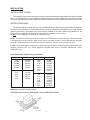
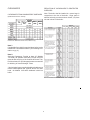
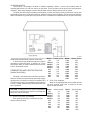
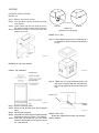
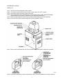
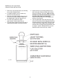
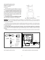
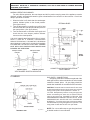
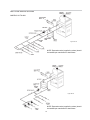
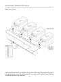
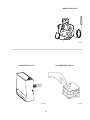
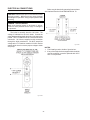
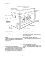
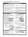
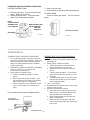
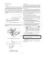
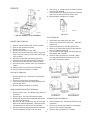
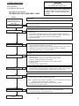
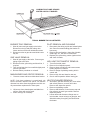
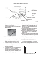
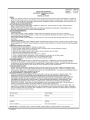
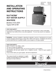
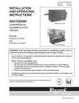
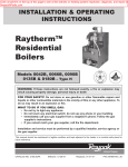
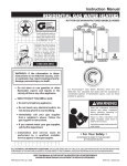
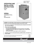
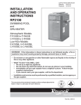
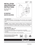
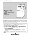
CATALOG NO.
Effective:
Replaces:
2000.50AB
08-14-07
11-15-05
INSTALLATION
AND OPERATING
INSTRUCTIONS
RAYTHERM™
HEATING BOILERS
Type H
Models 0133-4001
FOR YOUR SAFETY
Do not store or use gasoline or other flammable vapors and liquids or other combustible materials in the vicinity of this or any other appliance. To do so may result in an
explosion or fire.
WARNING: Improper installation, adjustment, alteration, service or maintenance can
cause property damage, personal injury or loss of life. Refer to this manual. Installation
and service must be performed by a qualified installer, service agency or the gas
supplier.
FOR YOUR SAFETY
WHAT TO DO IF YOU SMELL GAS
*Do not try to light any appliance.
*Do not touch any electrical switch; do not use any phone in your building.
*Immediately call your gas supplier from a neighbor's phone. Follow the gas supplier's
instructions.
*If you cannot reach your gas supplier, call the fire department.
This manual should be maintained in legible
condition and kept adjacent to the boiler or kept
in a safe place for future reference.
P/N 240035 Rev. 29
MODEL IDENTIFICATION
The model number of a boiler can be found on the Sales Order and the boiler's rating plate. The example below
identifies what the characters of the model number represent.
Boiler rating plate showing model number
MODEL NUMBER EXAMPLE:
H3-0514A
Series
Model Size
Representative of approximate MBTUH input
(Model 0514 has input of 511,500 BTUH)
Firing Mode
1 Mechanical Modulation
2 Motorized Modulation
3 2-Stage Firing / 4-Stage Firing Option
4 On-Off Firing
5 Low Temperature Mechanical Modulation
6 Motorized Modulation w/Electronic Outdoor Reset B6000
Application
H = Heating Boiler
TABLE OF CONTENTS
MODEL IDENTIFICATION........................................................................................2
RECEIVING EQUIPMENT........................................................................................4
CERTIFICATIONS.................................................................................................... 4
BOILER TYPES........................................................................................................ 4
CALIFORNIA PROPOSITION 65 WARNING.......................................................... 4
INSTALLATION........................................................................................................ 5
Installation Codes...............................................................................................5
Installation Base................................................................................................. 5
Clearances......................................................................................................... 6
Combustion and Ventilation Air..........................................................................7
Venting................................................................................................................8
Plumbing.............................................................................................................15
CONTROLS.............................................................................................................. 21
Economaster Controls........................................................................................21
Electronic Ignition............................................................................................... 21
Operating Controls............................................................................................. 21
Limit Controls......................................................................................................22
ELECTRICAL CONNECTIONS................................................................................ 24
START-UP................................................................................................................ 25
Before Start-up................................................................................................... 25
Lighting Instructions........................................................................................... 26
After Start-up...................................................................................................... 28
Inspections......................................................................................................... 29
LOW NOx BOILERS.................................................................................................30
Operation............................................................................................................30
Start-up...............................................................................................................30
Burner Adjustment............................................................................................. 30
Visual Inspection................................................................................................ 30
Electrical............................................................................................................. 30
Flame Roll-out Safety Switch.............................................................................30
Service................................................................................................................31
TROUBLESHOOTING..............................................................................................32
Electrical............................................................................................................. 32
Mechanical......................................................................................................... 35
SERVICE.................................................................................................................. 36
Tube Cleaning Procedure..................................................................................36
Burner Tray Removal......................................................................................... 37
Gas Valve Removal........................................................................................... 37
Main Burner and Orifice Removal..................................................................... 37
Pilot Removal and Cleaning.............................................................................. 37
High Limit or Tankstat Removal........................................................................ 37
Heat Exchanger Removal..................................................................................37
Combustion Chamber Removal........................................................................ 38
Control Well Replacement................................................................................. 39
Tube Replacement Procedure...........................................................................39
Cleaning Flue Gas Passageways......................................................................39
REPLACEMENT PARTS..........................................................................................39
WARRANTY............................................................................................................. 40
3
RECEIVING EQUIPMENT
BOILER TYPES
On receipt of the equipment, visually check for
external damage to the carton or the shipping crate. If
either is damaged, make a note on the Bill of Lading
and report the damage to the Carrier immediately.
Remove the boiler from the carton or the shipping
crate.
On occasion, items are shipped loose. Be sure
that you receive the number of packages indicated on
the Bill of Lading.
When ordering parts, you must specify the Model
and Serial Number of the boiler. When ordering under
warranty conditions, you must also specify the date of
installation.
Raypak recommends that this manual be
reviewed thoroughly before installing your Raypak
boiler. If there are any questions which this manual
does not answer, please contact the factory or your
local Raypak representative.
Claims for shortages and damages must be filed
with carrier by consignee. Permission to return goods
must be factory authorized and are subject to a
stocking charge.
Purchased parts are subject to replacement only
under the manufacturer's warranty. Debits for
defective replacement parts will not be accepted and
will be replaced in kind only per our standard
warranties.
TYPE H1 - MECHANICAL MODULATING
Central heating boiler with 150°-210°F
mechanical modulating gas valves and pressure relief
valve. Standard on models 133-1826.
TYPE H2 - MOTORIZED MODULATING
Central heating boiler with a motorized
modulating gas valve. Standard on models 21004001. Available as option on models 514-1826.
Modulating controller provided.
TYPE H3 - 2-STAGE CONTROLS
Central heating boiler with single two-stage gas
valve . Available as option on Models 183-4001. Twostage controller provided. Available with Y-1
sequencing option.
TYPE H4 - ON-OFF CONTROLS
Central heating boiler with on-off firing. Available
as option on Models 181-4001.
TYPE H5 - MECHANICAL MODULATING
Central heating boiler with 110°-170°F
mechanical modulating gas valves and pressure relief
valve. Standard on Models 133-1826.
CERTIFICATIONS
The Raypak hydronic boilers are design certified
and tested under the latest requirements of the
American National Standard, ANSI Z21.13. Each boiler
has been constructed and pressure tested in
accordance with the requirements of Setion IV of the
American Society of Mechanical Engineers Code, and
factory fire tested.
TYPE H6 - B6000 SYSTEM CONTROL
Central heating boiler for use with the B6000
boiler management system. Available for Models
514-4001.
TYPE H9 - 4-STAGE
All models are National Board approved.
Temperature and pressure gauge is standard.
Model 0133 has a 4-pass heat exchanger, 1 tube
per pass.
Models 0181-1826 have 2-pass heat exchangers,
5 tubes first pass, 4 tubes second pass.
Models 2100-4001 have 2-pass heat exchangers,
9 tubes per pass.
Models 926-4001 have optional single-pass heat
exchangers with cast iron headers only.
Central heating boiler for use with 4-stage firing.
Controller optional. Available option on Models 5144001.
CALIFORNIA PROPOSITION 65
WARNING:
This product contains chemicals known to the State
of California to cause cancer, birth defects or other
reproductive harm.
4
INSTALLATION
INSTALLATION CODES
The installation must conform with these instructions and the latest editions of the National Fuel Gas Code ANSI
Z223.1, the National Electric Code ANSI/NFPA 70 and local codes. All boiler installations must conform to ASME
boiler code. Hot water pipes must be installed with minimum clearances to combustible material as required by code.
INSTALLATION BASE
The boiler should be mounted on a level, non-combustible surface. Boiler must not be installed on carpeting.
The boiler can be installed on a combustible surface only when a suitable floor shield base is provided. Raypak
offers an optional floor shield base which can be factory installed on all indoor models except Model 133; the
Model 133 floor shield base is shipped loose and must be installed by the contractor.
Do NOT use the shipping crate base as an installation base.
NOTE: The boiler should be located in an area where water leakage will not result in damage to the area adjacent
to the appliance or to the structure. When such locations cannot be avoided, it is recommended that a suitable
drain pan, adequately drained, be installed under the appliance. The pan must not restrict air flow.
In addition, the boiler shall be installed such that the gas ignition system components are protected from water
(dripping, spraying, rain, etc.) during appliance operation and service (circulator replacement, control
replacement, etc.).
Combustible Floor Shield ordering information:
Boiler Model No. Base Part No. Boiler Model No. Base Part No.
133
182/181
260/261
330/331
400/401
001749
058313
058314
058315
058316
514
624
724
824
056199
056200
056201
056202
054597
054598
054599
054600
054601
058378
058379
926*
1083*
1178*
1287*
1414*
1571*
1758*
059233
962
059234
1125
059235
1223
059236
1336
059237
1468
059238
1631
059239
1826
* Models with factory-installed floor shield as standard.
BOLD type indicates Low NOx models.
ALTERNATE METHOD FOR PROVIDING A NON-COMBUSTIBLE BASE
Fig. #8148.1
5
CLEARANCES
REDUCTION OF CLEARANCES TO PROTECTED
SURFACES
CLEARANCES FROM COMBUSTIBLE SURFACES
Note: The boiler shall be installed in a space large in
comparison to the size of the boiler. Large space is
defined as having a volume at least sixteen (16) times
the total volume of the boiler.
(All dimensions are in inches)
133
MODEL
181 to 514 to 926 to 2100 to
824
1826
4001
401
Derived from National Fuel Gas Code, Table 6.2.3(a)
Note 1:
Combustible floor shield is required when boiler is to be
installed on a combustible surface. (See ordering information on pg. 4.)
Note 2:
Servicing Clearances: Provide at least 24" (Models
133-1826), 48" (Models 2100-4001) in front of unit for
removal and servicing of the Controls & Burner Tray.
Provide at least 18" on side opposite water connections
for deliming of Heat Exchanger Tubes.
*Vent includes factory-supplied drafthood and does not
include field-supplied vent systems above the drafthood. On Models 2100-4001 drafthood is built into
boiler.
Derived from National Fuel Gas Code, Table 6.2.3(b)
6
OUTDOOR BOILERS
These boilers are designed certified for outdoor installation. Boilers must not be installed under an
overhang within three (3) feet from the top on the boiler. Three (3) sides must be open in the area under the
overhang. Roof water drainage must be diverted away from the boilers with the use of gutters.
The point from where the flue products exit the boiler must be a minimum of four (4) feet below, four (4) feet
horizontally from or one (1) foot above any door, window or gravity inlet to a building. The top surface of the boiler
shall be at least three (3) feet above any forced air inlet, or intake ducts located within ten (10) feet horizontally.
Fig. #8245
Model Square Inches
133
136
182/181
181
260/261
264
330/331
334
400/401
399
514
512
624
627
724
726
824
825
962
962
HIGH-WIND CONDITIONS (Outdoor Units Only)
In areas where high winds are frequent, it may be
necessary to locate the boiler a minimum of 3' from
high vertical walls, or install a wind break so the boiler
is not in direct wind current.
COMBUSTION AND VENTILATION AIR
(Indoor Units Only)
The boiler must have both combustion and ventilation air. Minimum requirements for net free air supply
openings are 12 inches from ceiling for ventilation and
12 inches from the floor for combustion air as outlined
in Z223.1 - latest edition and any local codes that may
have jurisdiction.
Model
1125
1223
1336
1468
1631
1826
2100
2500
3001
3500
4001
Square Inches
1125
1223
1337
1467
1630
1826
2100
2499
3000
3500
4000
b. All Air From Outdoors:
When air is supplied directly from outside of building, each opening shall have a minimum net free
square inches as noted:
CAUTION: Combustion air must not be contaminated
by corrosive chemical fumes which can damage the
boiler and void the warranty.
Model
Square Inches
133
34
182/181
46
260/261
66
330/331
84
400/401
100
514
128
624
157
724
182
824
207
962
241
a. All Air From Inside The Building:
Each opening shall have a minimum net free
square inches as noted:
7
Model
1125
1223
1336
1468
1631
1826
2100
2500
3001
3500
4001
Square Inches
282
306
335
367
408
457
525
625
750
875
1000
VENTING
OUTDOOR INSTALLATIONS
MODEL 133
Step 1: Remove the front (4) screws.
Step 2: Line up outdoor top vent opening over heater
vent opening.
Step 3: Lower outdoor top onto unit lining up slots in
the outdoor top with screws holes in jacket top.
Step 4: Reinstall (5) screws to secure jacket top and
outdoor top to unit.
Fig. #RP8280.1
Detail A
Detail B
Outdoor Top
(Shipped Loose with Heater)
MODELS 514 - 824
Step 1: Lower outdoor top onto unit. Position top so it
is centered on unit from side to side and front
to rear.
Fig. #8114
MODELS 181-401 and 182-400
Outdoor Top Installation
Fig. # 8166.1
Step 2: Tighten the (4) screws (Shown below) until
they come in contact with the unit jacket top,
then evenly tighten all (4) screws to secure to
unit.
(Part of heater)
JACKET TOP
Fig. # 9389
FASTENING
SCREW
Step 1: Remove jacket top panel.
Step 2: Remove and discard inner stack adapter
panel.
Step 3: Install jacket top panel.
Step 4: Insert tabs of outdoor top into keyholes located
on jacket top panel (4 places). See Detail A
Step 5: Snap tabs on outdoor top into the locked
postion of the keyhole so the top will not pull
out. See Detail B
Fig. # 8233
MODELS 926-1758
Boilers are shipped with outdoor vent terminal
factory installed.
8
INDOOR INSTALLATIONS
MODEL 133
Step 1.
Step 2.
Step 3.
Step 4.
Shut-off main electrical power switch to boiler.
Turn heater manual switch located in upper control panel to the "OFF" position.
Shut-off gas supply and water supply to the boiler.
Mount drafthood on boiler and attach with the sheet metal screws provided. Drafthood should be
positioned with the vent sensor located on the front left side as shown below.
Step 5. Remove plastic plug from left side of boiler jacket and install the plastic grommet provided.
Step 6. Route flue sensor wire harness through the grommet installed in Step 5.
Step 7. Remove door and locate wire from roll-out sensor to high limit with the male/female connector.
Fig. #8946
Step 8. Disconnect male/female connector and attach to the 2 wires from drafthood vent sensor harness.
9
MODELS 181-401 and 182-400
INDOOR STACK INSTALLATION
1. Remove the louvered jacket top by removing
four (4) #10 flathead screws.
2. If originally installed, remove outdoor top
from the louvered jacket top.
3. Place the inner stack adapter panel over the
flue collector inside the heater. Make sure
the flanged side of the flue opening is up.
4. Turn the stack (drafthood) upside
down and set it down bottom side up.
5. Turn the jacket top panel (removed in step 1)
upside down and place it through the stack.
6. Attach the three (3) mounting brackets to the
stack using the screws provided and the holes
that are pre-drilled in the stack. Make sure the
brackets are positioned with the flange near the
top side of the stack (see illustration).
Caution must be taken not to over tighten and
strip the screw threads.
7. Turn the assembled stack and jacket top, rightside up. The jacket top will be trapped between the
brackets and the top of the stack. Place the stack
over the inner stack adapter panel flanged hole
and lower the louvered jacket top panel back into
its original position. Reinstall the four (4) #10
flathead screws removed in step 1 above.
Fig. #8246.5
10
MODELS 181-401 and 182-400
Step 1.
Step 2.
Step 3.
Step 4.
Step 5.
Step 6.
Step 7.
Step 8.
Shut-off main electrical power switch to boiler.
Turn heater manual switch located in upper control panel to the "OFF" position.
Shut-off gas supply and water supply to the boiler.
Mount drafthood on top of boiler as shown on page 8. Drafthood should be positioned with the vent
sensor located on the front right side as shown.
Remove plastic plug from left side of boiler jacket and install plastic grommet provided.
Route flue sensor wire harness through the grommet installed in Step 5.
Remove door and locate wire from roll-out sensor to high limit with the male/female connector.
Disconnect male/female connector and attach to the 2 wires from drafthood vent sensor harness.
BOILER BEFORE
DRAFTHOOD
INSTALLATION
Fig# 9349
BOILER AFTER
DRAFTHOOD
INSTALLATION
Fig# 9351
11
MODELS 514-824
MODELS 2100-4001
Locate and assemble as shown below. Secure with
screws supplied in envelope in carton.
These models have built-in drafthoods. For proper
operation, the drafthood outlet must be connected to
the venting system.
VENT PIPING
WARNING: Indoor boilers require a drafthood that
must be connected to a vent pipe and properly vented
to the outside. Failure to follow this procedure can
cause fire or fatal carbon monoxide poisoning.
Vent piping the same size or larger than the
drafthood outlet is recommended, however, when the
total vent height is at least 10 ft. (drafthood relief
opening to vent terminal), the vent pipe size may be
reduced as specified in Chapter 10 of the latest edition
of the National Fuel Gas Code, ANSI Z223.1. As much
as possible avoid long horizontal runs of vent pipe and
too many elbows. If installation requires horizontal
non-vertical runs, the vent pipe must have a minimum
of 1/4 inch per foot rise and should be supported at not
more than 5 ft. intervals. Plumbers tape, criss-crossed,
will serve to space both horizontal and vertical piping.
Gas vents supported only by the flashing and extending above the roof more than 5 ft. should be securely
guyed or braced to withstand snow and wind loads. We
recommend the use of insulated vent pipe spacers
through the roof and walls.
For protection against rain or blockage by snow, the
vent pipe must terminate with a vent cap which complies with the local codes or, in the absence of such
codes, to the latest edition of the National Fuel Gas
Code, ANSI Z223.1.
The discharge opening must be a minimum of 2 ft.
vertically from the roof surface and at least 2 ft. higher
than any part of the building within 10 ft.
Fig. # 8167.0
MODELS 962-1826
Locate and assemble as shown below. Secure with
screws supplied in envelope in carton.
Fig. # 8165.0
12
10' or less
Vent stack shall be at least 5 ft. in vertical height
above the drafthood outlet. The vent cap location shall
have a minimum clearance of 4 feet horizontally from,
and in no case above or below, unless a 4-foot horizontal distance is maintained, from electric meters, gas
meters regulators and relief equipment.
The weight of the vent stack or chimney must not rest
on boiler drafthood. Support must be provided in compliance with applicable codes. The boiler top and
drafthood must be readily removable for maintenance
and inspection. Vent pipe should be adequately supported to maintain proper clearances from combustible
construction.
Type "B" double-wall or equivalent vent pipe is recommended. However single-wall metal vent pipe may
be used as specified in the latest edition of the National
Flue Gas Code ANSI Z223.1.
Vent Cap
2' min.
2' min.
5' min.
Vent Pipe
Drafthood
Heater
Manifolds that connect more than one
boiler to a common chimney must be
sized to handle the combined load. Consult available guides for proper sizing of
the manifold and the chimney. At no time
should the area be less than the area of
the largest outlet.
Fig. #8119.0
(d)
(e)
(f)
Fig. #7043.1
At the time of removal of an existing boiler, the following
steps shall be followed with each appliance remaining
connected to the common venting system placed in
operation, while the other appliances remaining connected to the common venting system are not in
operation.
(a) Seal any unused openings in the common venting
system.
(b) Visually inspect the venting system for proper size
and horizontal pitch and make sure there is no
blockage or restriction, leakage, corrosion and
other deficiencies which could cause an unsafe
condition.
(c) Insofar as is practical, close all building doors and
windows and all doors between the space in which
the appliances remaining connected to the common venting system are located and other spaces
of the building. Turn on clothes dryers and any
(g)
appliance not connected to the common venting
system. Turn on any exhaust fans, such as range
hoods and bathroom exhausts, so they will operate at maximum speed. Do not operate a summer
exhaust fan. Close fireplace dampers.
Place in operation the appliance being inspected.
Follow the lighting instructions. Adjust thermostat
so appliance will operate continuously.
Test for spillage at the drafthood relief opening
after 5 minutes of main burner operation. Use the
flame of a match or candle, or smoke from a
cigarette, cigar or pipe.
After it has been determined that each appliance
remaining connected to the common venting system properly vents when tested as outlined above,
return doors, windows, exhaust fans, fireplace
dampers and any other gas burning appliance to
their previous conditions of use.
Any improper operation of the common venting
system should be corrected so that the installation
conforms with the latest edition of the National Fuel
Gas Code, ANSI Z223.1. When re-sizing any
portion of the common venting system, the common venting system should be re-sized to
approach the minimum size as determined using
the appropriate tables in Part 11 of the National
Fuel Gas Code, ANSI Z223.1.
For special venting applications that require reduced
vent sizes and through-the-wall venting, the Type D
Induced Draft Assembly can be used. Consult the
factory or your local Raypak representative.
13
VENT DAMPER INSTALLATION
(MODELS 133 THROUGH 261)
WHERE REQUIRED
LOCATION
The vent damper must be located in the vent so
that it serves only the appliance for which it is intended.
If improperly installed, a hazardous condition, such
as an explosion or carbon monoxide poisoning, could
result. Make certain that it is mounted in an accessible
location at least 6 inches from any combustible material or the heat exchanger, and that the position indicator is in a visible location.
The vent damper must be installed after the appliance drafthood, as close to the drafthood as practicable, and without modification of the drafthood.
Fig. # 8182.0
Note: Model 133 drafthood shown.
WARNING: Do not use thermally actuated vent dampers on a modulating boiler. To do so, may result in
asphyxiation. Use only a mechanically actuated vent damper device that is electrically interlocked with the
modulating boiler operation.
On vertical vents, the vent damper may be mounted with the actuator in any position. On horizontal vents,
do not mount the actuator either directly above or directly below the vent pipe; mount the vent damper actuator
to the side of the vent.
The vent damper is set up for a continuous pilot system. If the vent damper is installed on an Intermittent
Pilot or Direct Spark Ignition equipped system, the energy savings of the vent damper can be improved by
plugging the hole in the vent damper blade using the knockout plug, Part No. 105612R, provided in the parts
envelope.
DO NOT plug the hole if installing the vent damper on a continuous pilot system as this will create a hazard.
HORIZONTAL INSTALLATION
FLOW >
D808
NO
N.O.
N.C.
End
YES
TO BOILER
D808
1K2
Switch
YES
C.
1K1
TO CHIMNEY
Motor
R
NO
VERTICAL
1K3
1R
INSTALL VENT
INSTALLATION
TO CHIMNEY
DAMPER WITH
1
2
3
ACTUATOR TO
Black
SIDES OF VENT
Orange
5
Blue
Optional Limit
Limit
ONLY. DO NOT
D808
4
Yellow
Red
Location
Thermostat or
MOUNT ABOVE OR
Controller
BELOW VENT.
L1
(Hot)
Dual Valve
Control or
INSTALLED IN ANY
TO BOILER
L2
Combination Gas
ACTUATOR MAY BE
1
Transformer
Ignition System
POSITION ON
1
VERTICAL PIPE.
Fig. # 8183.0
Power
provide
disconnect
me means an overload
ans an overload
protection
as requ
Powersupply
supply
provide
disconnect
protection
as required.
ired.
Fig. # 8615.0
VENT DAMPER INSTALLATION
VENT DAMPER GENERAL WIRING DIAGRAM
14
INSTALL THE VENT DAMPER TO SERVICE ONLY THE SINGLE APPLIANCE FOR WHICH IT IS INTENDED. IF
IMPROPERLY INSTALLED, A HAZARDOUS CONDITION, SUCH AS AN EXPLOSION OR CARBON MONOXIDE
POISONING, COULD RESULT.
VENT DAMPER
NORMAL OPERATION SUMMARY
For safe, efficient operation, the vent damper and all flue product carrying areas of the appliance must be
checked annually, with particular attention given to deterioration from corrosion or other sources. Check vent
damper operation as follows:
1. When the boiler is off, check that the vent damper
position indicator points to the closed position.
(See figure below.)
2. Turn the thermostat or controller up to call for heat
and check that the vent damper indicator points to
the open position. (See figure below.)
3. Turn the thermostat or controller down again and
check that the vent damper position indicator
returns to the closed position.
EFFIKAL® RVGP
THE VENT DAMPER MUST BE INSPECTED AT LEAST
ONCE A YEAR BY A TRAINED, EXPERIENCED
SERVICE TECHNICIAN. THE NAME OF THE PERSON
WHO ORIGINALLY INSTALLED YOUR VENT DAMPER
IS SHOWN ON THE INSTALLATION LABEL. DAMPER
MUST BE IN OPEN POSITION WHEN BOILER MAIN
BURNERS ARE OPERATING.
Damper Position
Indicator
Damper Position
Indicator
Fig. # 8181.0
DAMPER OPEN
CONNECTION DIAGRAM FOR EFFIKAL®
VENT DAMPER
DAMPER CLOSED
VENT DAMPER POSITON INDICATOR
PLUMBING
GAS SUPPLY CONNECTIONS
Gas piping must have a sediment trap ahead of the
boiler gas controls, and a manual shut-off valve located
outside the heater jacket. All gas piping should be
tested after installation in accordance with local codes.
CAUTION: The boiler and its manual shut-off valve must
be disconnected from the gas supply during any pressure
testing of that system at test pressures in excess of
1/2 PSIG. Dissipate test pressure in the gas supply line
before reconnecting the boiler and its manual shut-off
valve to gas supply line. FAILURE TO FOLLOW THIS
PROCEDURE MAY DAMAGE THE GAS VALVE. OVER
PRESSURED GAS VALVES ARE NOT COVERED BY
WARRANTY. The boiler and its gas connections shall be
leak tested before placing the appliance in operation. Use
soapy water for leak test do NOT use open flame.
NOTE: Do not use teflon tape on gas line pipe thread.
A flexible sealant is recommended.
Fig. # 8090.1
15
A minimum of 7" W.C. and a maximum of 10.5" W.C. upstream pressure, under load and no-load conditions,
must be provided for natural gas, or a minimum of 12" W.C. and a maximum of 13" for propane.
*Low NOx units not available for propane.
GAS PRESSURE REGULATOR
The gas pressure regulator is preset nominally at 4" W.C. for natural gas, and 11" W.C. for propane. Between
the gas valve and the burners is a 1/8" pipe plug. The pressure at this point, taken with a manometer, should
be about 3.7" W.C. for natural gas and 10.5" W.C. for propane. Low NOx models should be 3.9" W.C., natural
gas only. If an adjustment is needed, turn adjustment screw clockwise to increase pressure, or counter-clockwise
to decrease pressure.
For boilers with mechanical modulation gas valves (Type H1 and H5) or two-stage gas valves (Type H3),
the gas pressure regulator is preset and sealed, and not field adjustable. Pressure tap is provided on the outlet
side of the gas valve for measurement of gas pressure in the manifold.
VENTING OF DIAPHRAGM GAS COMPONENTS
Gas valves that are equipped with a gas bleed must be vented to the outdoors as required by the National
Fuel Gas Code. Under NO circumstances shall bleed lines terminate in the gas utilization equipment flue or
exhaust system.
Bleed Line Connection
Fig. # 8185.2
GENERAL
Boiler should be located so that any water leaks will not cause damage to any adjacent areas or structures.
See piping diagrams for proper water connections for the type of boiler and system.
16
EXCHANGER
PUMP SELECTION
In order to ensure proper hydraulics in your
hydronic heating system, adequate pump size must be
selected. We recommend that the pump be sized for
20°F Delta T. (Delta T is the temperature difference
between the inlet and outlet water when the boiler is
firing at full rate). For some boilers, the Delta T is more
than 20°F (22°-33°F) at the recommended flow rates.
RECOMMENDED PURGE MANIFOLDS FOR
TYPICAL HYDRONIC SYSTEM HOOKUPS
The boiler piping system of a hot water heating
boiler connected to heating coils located in air handling
units where they may be exposed to refrigerated air
circulating, must be equipped with flow control valves
or other automatic means to prevent gravity circulation
of the boiler water during the cooling cycle.
FEEDWATER REGULATOR
We recommend that a feedwater regulator be
installed and set at 12 PSIG minimum pressure. Install
a check valve or back flow device upstream of the
regulator, with a manual shut-off valve. Leave the
valve open.
TEMPERATURE & PRESSURE GAUGE
The temperature & pressure gauge is standard
equipment on all hydronic heating and hot water supply
boilers. All temperature & pressure gauges are factory
mounted in the in/out header except for residential
boilers, Models 133 and 181-401. On these models the
temperature & pressure gauge is shipped loose for
field installation, and located in the outlet water
connection. All fittings required to mount gauge to
piping system are supplied by others.
PIPING - HEATING BOILERS
We recommend that all high points be vented and
that purge valves and a bypass valve be installed. A
boiler installed above radiation level must be provided
with a low water cut-off device. The boiler, when used
in conjunction with a refrigeration system, must be
installed so that the chilled medium is piped in parallel
with the boiler with appropriate valves to prevent the
chilled medium from entering the boiler.
17
PIPING DIAGRAMS
DIAPHRAGM TANK SYSTEM
7024e
NOTE: Expansion tanks (supplied by others) should be
installed per manufacturer's instructions.
18
MULTI-ZONE HEATING SYSTEMS
MODELS 133 TO 4001
Fig.# 7027.1e
NOTE: Expansion tanks (supplied by others) should
be installed per manufacturer's instructions.
Fig.# 7024.1e
NOTE: Expansion tanks (supplied by others) should
be installed per manufacturer's instructions.
19
MULTIPLE-BOILER– REVERSE RETURN HOOK-UP
MODELS 133 TO 4001
REVERSE RETURN PIPING IS A PROPER METHOD OF MANIFOLDING MULTIPLE BOILER HOOK-UPS TO
ENSURE BALANCED FLOW THROUGH EACH BOILER. VALVES ON SUPPLY AND RETURN ARE NEEDED
TO ISOLATE ANY BOILER, AS REQUIRED.
20
CONTROLS
OPERATING CONTROLS
ECONOMASTER CONTROLS
Models 133-1826 with mechanical modulating
controls have one or more Robertshaw Unitrol 7000
Series hydraulic snap-on thermostatic combination
gas valves. These valves have the pressure regulator
and 24 volt operator built-in. The hydraulic actuator
will throttle the boiler input to adjust the firing rate and
meet the required load. This, in effect, prevents costly
fuel consumption, as compared to an on-off cycling
boiler. The valve has a remote capillary bulb immersed in a well, at the header outlet, to maintain a
constant outlet water temperature. When multiple
valves are furnished, they can be staged to give
greater flexibility of control. Standard factory setting is
at position 5. Consult the dial setting tag attached to
the control for your desired temperature. See sample
tag drawings below.
The Economaster II is an electronic device that
allows the operator to set the desired time for the pump
to run after the boiler shuts off. The time is factory-set at
7 minutes and it can be re-adjusted in the field anywhere
from 3 to 10 minutes.
In a conventional system, when the aquastat is
satisfied, the main gas valve closes, but the pump
continues operating. With the new energy-conserving
Economaster II the boiler pump is programmed to
continue running for an optimum period of time in order
to absorb the residual heat from the combustion chamber and use it in the system. The pump then shuts off
until the next call for heat is received from the aquastat.
3/4
NOTE: Pump will come on when power is first applied
to boiler.
Fig. #8645.1
ACAD: ECONO. DWG.
ELECTRONIC IGNITION
LOW TEMP. RANGE
HIGH TEMP. RANGE
The intermittent ignition device conserves energy
by automatically extinguishing the pilot when desired
temperature is reached. When additional heat is
needed, the pilot re-ignites electrically, eliminating the
fuel costs of maintaining a constant pilot. To ensure
safe operation, the gas valve cannot open until the pilot
relights and is proven.
All units are shipped with lockout ignition module
as standard.
IGNITION MODULE
ELECTRONIC SAFETY
Fig. #8645
21
Fig. # 8929.1
MODULATING VALVES
W/ BUILT-IN REGULATOR
Fig. #8643
MODULATING VALVE LOCATION
THERMOSTAT CONTROL
LIMIT CONTROLS
HIGH LIMIT
The boiler is equipped with a manual reset high
limit. Push the reset button and set the limit(s) to 3040 °F above desired operating temperature.
rupted. Pilot flame is automatically lit when the device
is powered. Unit performs its own safety check and
opens the main valve only after the pilot is proven to be
lit.
FLOW SWITCH
This dual purpose control shuts off the boiler in the
case of a pump failure or low water condition. It is
mounted and wired in series to the main gas valve.
Standard on all models except the 133.
NOTE: Flow switch will not operate if flow is less than
12 GPM.
LOW WATER CUT-OFF (OPTIONAL)
The low water cut-off automatically shuts down
burner whenever water level drops below probe. 90second time delay prevents premature lockout due to
temporary conditions such as power failure or air
pockets. Flush float type devices at beginning of each
heating season.
100% PILOT SAFETY
All standard boiler models 514-4001 employ electronic devices which close the main gas valve within
8/10 of a second whenever the pilot flame is inter-
HIGH AND LOW GAS PRESSURE SWITCHES
These switches sense either high or low gas pressures and automatically shut down burners if abnormal
pressures exist.
MANUAL RESET HIGH LIMIT
FLOW SWITCH
Fig. #8644
22
MODULATING VALVE
Fig. #8995
LOW WATER CUT-OFF
GAS PRESSURE SWITCH
Fig. #8996
Fig. #8236
23
ELECTRICAL CONNECTIONS
Boiler must be electrically grounded in accordance
with National Electrical Code ANSI/NFPA No 70.
CAUTION: Label all wires prior to disconnection when
servicing controls. Wiring errors can cause improper
and dangerous operation. Verify proper operation after
servicing.
DANGER - SHOCK HAZARD
Make sure electrical power to the heater is disconnected to avoid potential serious injury or damage to
components.
The boiler is normally wired for 120 Volts. The
voltage is indicated on the tie-in leads. Consult the
wiring diagram shipped with the boiler in the instruction
packet. The "TH" leads are for the remote tank control
connection. 24 Volts are supplied to this connection
through the boiler transformer. DO NOT attach line
voltage to the "TH" leads on models 133-1826. Before
starting boiler check to ensure proper voltage to boiler
and pump.
Fig. #9138.1
NOTES:
1. Field install ground to inside of junction box.
2. If any of the original wire as supplied with the boiler
must be replaced, it must be replaced with 105°C
wire or its equivalent.
-
Fig. #9138.2
24
START-UP
HIGH LIMIT
Fig. #8991
ETHYLENE GLYCOL SYSTEMS HEATING BOILERS
Fill through filler opening on the top on the
Air-X Tank to solution desired. Always maintain solution level in sight glass.
BEFORE START-UP
Safe lighting and other performance criteria were
met with the gas manifold and control assembly provided on the boiler when the boiler underwent tests
specified in the latest edition of ANSI-Z21.13 Standard.
INITIAL START-UP - PUMP AND MOTOR
Many pumps are now direct-drive. They have no
coupler or bearing assembly. These pumps do not
require lubrication. Others require SAE-30 non-detergent oil to lubricate both the motor and the bearing
assembly. Check pump motor for type before attempting to oil.
Clean dust and lint from pump and motor. Check
pump coupler and tighten if necessary.
Flush system before putting into operation to ensure that foreign material does not damage pump
seals.
GENERAL
Before lighting up a new installation, water should
be flowing through the boiler. Regulator should be set
to minimum 12 PSI.
CAUTION:
Liquefied petroleum gas is heavier than air and
sinks to the ground. Exercise extreme care in lighting
boiler in confined areas.
FILLING SYSTEM - HEATING BOILERS
Fill system with water. Purge all air from the system
using purge valve sequence. After system is purged of
air, lower system pressure. Open valves for normal
system operation. Fill system through feed pressure.
Manually open air vent on the compression tank until
water appears, then close vent.
CAUTION:
A. Pump must be off to check oil in bearing assembly.
B. Do not run pump without water in system.
25
START-UP
LIGHTING INSTRUCTIONS FOR BOILERS WITH STANDING PILOT. For Models 133, 182, 260, 330 & 400
FOR YOUR SAFETY READ BEFORE LIGHTING
WARNING: If you do not follow these instructions exactly, a fire or explosion may
result causing property damage, personal injury or loss of life.
A. This appliance has a pilot which must be lighted
by hand. When lighting the pilot, follow these
instructions exactly.
•
If you cannot reach your gas supplier, call
the fire department.
C. Use only your hand to push in or turn the gas
control knob. Never use tools. If the knob will
not push in or turn by hand, don’t try to repair it,
call a qualified service technician. Force or attempted repair may result in a fire or explosion.
B. BEFORE LIGHTING smell all around the appliance area for gas. Be sure to smell next to the
floor because some gas is heavier than air and
will settle on the floor.
WHAT TO DO IF YOU SMELL GAS
• Do not try to light any appliance.
• Do not touch any electric switch; do not use
any phone in your building.
• Immediately call your gas supplier from a
neighbor’s phone. Follow the gas supplier’s
instructions.
D. Do not use this appliance if any part has been
under water. Immediately call a qualified
service technician to inspect the appliance and
to replace any part of the control system and
any gas control which has been under water.
LIGHTING INSTRUCTIONS
1. STOP! Read the safety information above on
this label.
2. Set the thermostat to lowest setting.
3. Turn off all electric power to the appliance.
4. Remove boiler door panel.
5. Push in gas control knob slightly and turn
clockwise
to “OFF”.
GAS CONTROL
KNOB SHOWN
IN "OFF"
POSITION
GAS INLET
PILOT
BURNER
7. Locate pilot mounted
on the right side of the
burner tray, and right
of first burner.
8. Turn knob on gas control
counter-clockwise
to "PILOT"
9. Push in control knob all the way and hold in .
GAS CONTROL
KNOB SHOWN
IN "OFF"
POSITION
Fig. # 8081.0
GAS INLET
THERMOCOUPLE
Fig. # 8243.0
NOTE: Knob cannot be turned from “PILOT” to “OFF”
unless knob is pushed in slightly. Do not force.
6. Wait five (5) minutes to clear out any gas. Then
smell for gas, including near the floor. If you
smell gas, STOP! Follow “B” in the safety information above on this label. If you don’t smell
gas, go to next step.
10.
11
12.
13
Immediately light the pilot with a match. Continue
to hold the control knob in for about one (1) minute
after the pilot is lit. Release knob and it will pop
back up. Pilot should remain lit. If it goes out, repeat steps 5 through 9.
• If knob does not pop up when released, stop
and immediately call your service technician
or gas supplier.
• If the pilot will not stay lit after several tries,
turn the gas control knob to “OFF” and call
your service technician or gas supplier.
Stand to the side of the boiler and turn the gas
control knob counter-clockwise
to "ON".
Replace boiler door panel.
Turn on all electric power to the appliance.
Set the thermostat to the desired setting.
TO TURN OFF GAS TO APPLIANCE
1. Set the thermostat to lowest setting.
2. Turn off all electric power to the appliance.
3. Remove boiler door.
4. Push in gas control knob slightly and turn clockwise
to “OFF”. Do not force.
5. Replace boiler door panel.
26
LIGHTING INSTRUCTIONS FOR BOILERS WITH ELECTRONIC IGNITION (IID)
For Models with Manual Gas Valves
FOR YOUR SAFETY READ BEFORE OPERATING
WARNING: If you do not follow these instructions exactly, a fire or explosion may result causing
property damage, personal injury or loss of life.
A.
This appliance is equipped with an ignition device which
automatically lights the pilot. Do not try to light the pilot
by hand.
B.
BEFORE OPERATING smell all around the appliance
area for gas. Be sure to smell next to the floor because
some gas is heavier than air and will settle on the floor.
WHAT TO DO IF YOU SMELL GAS
Do not try to light any appliance.
Do not touch any electric switch; do not use any phone
in your building.
Immediately call your gas supplier from your neighbor’s
phone. Follow the gas supplier’s instructions.
*
*
*
*
If you cannot reach your gas supplier, call the fire department.
C.
Use only your hand to push in or turn the gas control
knob. Never use tools. If the knob will not push in or turn
by hand, do not try to repair it, call a qualified service
technician. Force or attempted repair may result in a fire
or explosion.
D.
Do not use this appliance if any part has been under
water. Immediately call a qualified service technician to
inspect the appliance and to replace any part of the
control system and any gas control which has been
under water.
OPERATING INSTRUCTIONS
1.
2.
3.
4.
5.
6.
7.
8.
STOP! Read the safety information above.
Set the thermostat on the lowest setting.
Turn off all electrical power to the appliance.
This appliance is equipped with an ignition device which
automatically lights the pilot. Do not try to light the pilot
by hand.
Remove boiler door panel.
For Robertshaw gas valve: Turn gas control knob
clockwise
to “OFF”.
For Honeywell gas valve (all models except 40#):
Turn gas control knob clockwise
to “OFF".
Make sure knob rest against stop.
For Honeywell gas valve (Models 40# only):
Push in gas control knob slightly and turn clockwise
to “OFF”. Knob cannot be turned to “OFF”
unless knob is pushed in slightly. Do not force.
Wait five (5) minutes to clear out any gas. Then smell
for gas, including near the floor. If you smell gas, STOP!
Follow “B” in the safety information above. If
you do not smell gas, go to the next step.
For Robertshaw gas valve: Turn gas control knob
counter-clockwise
to “ON”.
For Honeywell gas valve: Turn gas control knob
counter-clockwise
from “OFF” until it
stops. Push in gas control knob and continue
rotating counter-clockwise
to “ON”
position. Make sure knob rests against stop.
HONEYWELL
GAS CONTROL
KNOB SHOWN
IN "ON" POSITION
GAS INLET
Fig. # 8082
For Honeywell gas valve (Models 40# only):
Turn gas control knob counter-clockwise
to “ON”.
GAS CONTROL KNOB
SHOWN IN "ON"
POSITION
GAS INLET
ROBERTSHAW
GAS CONTROL
KNOB SHOWN
IN "ON" POSITION
9.
10.
11.
12.
GAS INLET
Fig. # 8080
Fig. #8219
Replace boiler door panel.
Turn on all electrical power to the appliance.
Set thermostat to desired setting.
If the appliance will not operate, follow the instructions
“To Turn Off Gas To Appliance” and call your service
technician or gas supplier.
TO TURN OFF GAS TO APPLIANCE
1.
2.
3.
4.
Set the thermostat to the lowest setting.
Turn off all the electrical power to the appliance if service
is to be performed.
Remove door panel.
For Robertshaw gas valve: Turn gas control knob
clockwise
to “OFF”.
For Honeywell gas valve (all models except 40#):
5.
27
Turn gas control knob clock-wise
to “OFF”.
Make sure knob rests against stop.
For Honeywell gas valve (Models 40# only):
Push in gas control knob slightly and turn clockwise
to “OFF”.
Replace heater door panel.
FOR MODELS WITH AUTOMATIC GAS VALVES
LIGHTING INSTRUCTIONS
3. Open main gas valve.
4. Set temperature controls to desired temperature.
1. Close all gas valves. Turn off electrical power
supply. Wait five (5) minutes.
2. Open manual pilot valve. Turn on electrical
power. Pilot is automatically lighted.
PILOT
VALVE CONTROL
SHOWN IN THE
"ON" POSITION
TO SHUT DOWN
Close all manual gas valves. Turn off electrical
power.
MAIN GAS SHUT-OFF
VALVE SHOWN IN
THE "ON"
POSITION
IGNITION MODULE
GAS INLET
Fig. # 8220.0
Fig. # 8929.1
AFTER START-UP
INTERMITTENT PILOT SYSTEM CHECKOUT
(S8600)
1. Turn on power to the ignition systems and turn
gas supply off.
2. Check ignition module as follows:
a. Set the thermostat or controller above
room temperature to call for heat.
b. Watch for continuous spark at the pilot
burner.
c. Time the spark operation. Time must be
within the lockout timing period (15 or 90
seconds).
d. Turn thermostat down to end call for heat
and wait 60 seconds on lockout models
before beginning step 3.
3. Turn on gas supply.
4. Set thermostat or controller above room temperature to call for heat.
5. Systems should start as follows:
a. Spark will turn on and pilot gas valve will
open at once. Pilot burner should ignite
after gas reaches the pilot burner.
b. Spark ignition should cut-off when pilot
flame is established.
c. Main gas valve should open and main
burner should ignite after gas reaches the
burner port.
STANDING PILOT CHECKOUT PROCEDURE
1. Turn on pilot gas supply, light pilot, and check
pilot tubing connections for leakage. With main
burner in operation, paint tubing connections
with a rich soap and water solution. Bubbles
indicate a gas leak.
2. Adjust pilot to obtain a normal flame enveloping
3/8 to 1/2 inch [9.5 to 12.5 mm] of the
thermcouple or generator tip.
3. Place system in operation, and:
a. Check for satisfactory ignition of main
burner.
b. Make certain the pilotstat "holds in", and
that shutdown occurs within 2-1/2 minutes
after the pilot flame is extinguished.
c. Observe operation for at least three cycles
to be sure the system is functioning normally.
PILOT FLAME SHOULD ENGULF THERMOCOUPLE
PILOT WITH
BURNER FLAME
Fig. # 8186.1
STANDING PILOT
28
CONTROLS
Check all controls to see that they are operational.
To check electronic safety (IID Models), turn off main
burner. Observe pilot burner when shutting off pilot
gas. Ignition spark should go on. Main gas valve will
also drop out.
To check high limit switch, turn dial setting down to
a point slightly below the temperature of the water
leaving the heater. The reset button should snap out
and the burner should shut-off. Reset dial to 30°F to
40°F above desired operating temperature, and push
reset button. Burner should light.
INSPECTIONS
BURNERS
Clean main burners and air louvers of dust, lint and
debris. Keep boiler area clear and free from combustibles and flammable liquids. Do not obstruct the
flow of combustion and ventilation air. Make visual
check of burner and pilot flame. Yellow flame indicates
clogging of air openings. Lifting or blowing flame indicates high gas pressure. Low flame indicates low gas
pressure.
TYPICAL MAIN BURNER FLAME
SUGGESTED INSPECTION SCHEDULE
The boiler should be inspected on the first and third
months after initial start-up and then on an annual
basis. If problems are found, refer to Troubleshooting
Guide for additional directions.
1. Remove top of heater and inspect heat exchanger
for soot and examine venting system.
2. Remove rear header and inspect for scale deposits, and/or accelerated erosion.
*3. Inspect pilot and main burner flame and firing rate.
*4. Inspect and operate all controls and gas valve.
*5. Visually inspect system for water leaks.
*6. a. Oil pump motor and bearing assembly, if oil
cups are provided.
b. Disconnect pump from header and check
condition of pump impeller. Check condition
of bearing by attempting to move impeller
from side to side. Replace any parts showing
wear.
c. Check pump coupler for wear and vibration.
7. Check flow switch paddle.
8. Clean room air intake openings to ensure adequate flow of combustion and ventilation air.
CAUTION: Combustion air must not be contaminated
by corrosive chemical fumes which can damage the
boiler and void the warranty.
9. Keep boiler area clear and free from combustible
materials, gasoline, and other flammable vapors
and liquids.
*Should be checked monthly. (Takes approximately
15 minutes).
Fig. # 8144
NOTE: Modulating burner flame varies in height from
approximately 1/4" at low fire to approximately 4" at
high fire.
Fig #9336
PILOT BURNER FLAME (IID UNITS)
Fig #8964.1
PILOT BURNER FLAME
(STANDING PILOT UNITS)
29
LOW NOx BOILERS Models 181 to 401
The boilers are certified and tested under the latest
edition of the ANSI Z21.13 standards for hot water
boilers.
BURNER ADJUSTMENT
This burner assembly does not require any primary air
adjustments.
The boiler should be installed to meet the latest edition
of all local codes, the National Fuel Gas Code Z223.1
and the National Electrical Code, ANSI/NFPA 70.
VISUAL INSPECTION
Flame can be observed through the slot opening above
the plenum. Flame color is blue and evenly spread on
the top surface of the burner. At least every three
months a visual inspection should be made of the
burners. In case flame lifting is observed, check gas
pressure on manifold and static pressure in plenum.
Gas pressure in manifold should be 3.9" W.C. and
static pressure in plenum should be greater than 0.5"
W.C.
ELECTRICAL
Be sure that electrical service to the boiler has proper
overload fuse or circuit breaker protection and wire
size, and connections which comply with all applicable
codes.
FLAME ROLL-OUT SAFETY SWITCH
The boiler is equipped with a cut-off device to prevent
flame roll-out in the event the heat exchanger becomes
blocked. This is a "manual reset" type roll-out switch,
that must be reset by a service technician after any over
temperature conditions have been fixed. Excessive
restriction in the heat exchanger flue passage may
cause the switch to disable the boiler.
Fig # 9361
OPERATION
On call for heat, the ignition system, consisting of an
electronic spark module, and gas pilot system is energized. Providing pilot is proven, blower will start
running, the main gas valve will open and the boiler will
operate. When the operating control is satisfied the
boiler will shut down.
START-UP (S8610B)
1.Turn on power to the boiler with gas supply off.
2.Check ignition module as follows:
a. Set the thermostat or controller to call for heat.
b. Watch for continuous spark at the pilot burner.
c. Check the ignition spark operation. Time must be
within the lockout timing period (15 or 90 seconds).
d. Turn control down to end call for heat and wait 60
seconds on lockout models before beginning step
3.
3.Turn on gas supply.
4.Set controller to call for heat.
5.System should start as follows:
a. Spark will turn on and pilot gas valve will open and
the blower will begin running.
b. Heater will operate until call for heat is satisfied.
Fig. # 9412
30
SERVICE
6. Use a long ½” socket wrench to remove orifices
from the gas manifold.
7. Remove burners by raising the bracket on the back
end of the burners up and out of their slots.
8. Reverse above procedure to re-install.
Fig # 9363
Fig # 9362
IID PILOT
LOW NOx BURNER TRAY ASSEMBLY
PILOT REMOVAL
1. Disconnect pilot tubing from gas valve.
2. Remove (4) screws from control box. Open the
control box.
3. Remove the pilot wire from the ignition wire.
4. Remove (2) screws that mount the pilot bracket
to the air manifold assembly.
5. Pull the pilot bracket slightly, then drop and pull
downwards and outwards.
6. Reverse above procedure to re-install. Make
sure the pilot bracket is all the way up on the
pilot side, see drawing below.
BURNER TRAY REMOVAL
1.
2.
3.
4.
5.
Shut-off main electrical power switch to heater.
Shut-off gas upstream of heater.
Remove front door.
Disconnect gas line from gas valve.
Remove (2) screws that mount burner tray to the
base of the unit, and (2) screws that secure gas
valve to jacket.
6. Disconnect wires that terminate at gas valve.
7. Unscrew (4) screws that secure the control box.
8. Disconnect pilot wire from the ignition module.
9. Disconnect wire harness from the combustion
blower.
10. Carefully slide out the burner tray assembly.
11. Reverse above procedure to re-install.
GAS VALVE REMOVAL
1. Remove burner tray. See Burner Tray Removal
procedure.
2. Disconnect, pilot tubing from gas valve.
3. Turn vertical gas pipe from manifold slightly and
unscrew gas valve.
4. Reverse above procedure to re-install.
MAIN BURNER AND ORIFICE REMOVAL
FOR HEATERS
MADE IN OR AFTER
AUGUST 2001
1. Remove burner tray. See Burner Tray Removal
procedure.
2. Remove pilot. See Pilot Removal procedure.
3. Remove (8) total screws from the hold-down brackets, front and rear of tray.
4. Remove (8) total screws from the left and right
sides of the manifold assembly. Detach the manifold assembly from the burner tray assembly.
5. Remove burners by raising the bracket on the back
end of the burners up and out of their slots.
COMBUSTION FAN REMOVAL
1. Remove burner tray. See Burner Tray Removal
procedure.
2. Remove (4) screws that mount the combustion
blower to the manifold assembly.
3. Reverse above procedure to re-install.
31
TROUBLESHOOTING
ELECTRICAL
ELECTRONIC IGNITION IID
Intermittent Pilot System
TROUBLESHOOTING HONEYWELL S8600
START
TURN GAS SUPPLY OFF.
TURN THERMOSTAT
(CONTROLLER) TO CALL
FOR HEAT
POWER TO MODULE
(24 V NOMINAL)
YES
1234567890123456789012345678901212345678901234567890123456789012
1234567890123456789012345678901212345678901234567890123456789012
1234567890123456789012345678901212345678901234567890123456789012
1234567890123456789012345678901212345678901234567890123456789012
1234567890123456789012345678901212345678901234567890123456789012
WARNING
1234567890123456789012345678901212345678901234567890123456789012
1234567890123456789012345678901212345678901234567890123456789012
1234567890123456789012345678901212345678901234567890123456789012
HIGH
VOLTAGE
1234567890123456789012345678901212345678901234567890123456789012
1234567890123456789012345678901212345678901234567890123456789012
1234567890123456789012345678901212345678901234567890123456789012
1234567890123456789012345678901212345678901234567890123456789012
For
qualified
technicians
ONLY
1234567890123456789012345678901212345678901234567890123456789012
1234567890123456789012345678901212345678901234567890123456789012
1234567890123456789012345678901212345678901234567890123456789012
1234567890123456789012345678901212345678901234567890123456789012
1234567890123456789012345678901212345678901234567890123456789012
1234567890123456789012345678901212345678901234567890123456789012
1234567890123456789012345678901212345678901234567890123456789012
NOTE: Some heaters may be equipped with
1234567890123456789012345678901212345678901234567890123456789012
1234567890123456789012345678901212345678901234567890123456789012
1234567890123456789012345678901212345678901234567890123456789012
1234567890123456789012345678901212345678901234567890123456789012
an ignition module that shuts off pilot gas if
1234567890123456789012345678901212345678901234567890123456789012
1234567890123456789012345678901212345678901234567890123456789012
1234567890123456789012345678901212345678901234567890123456789012
pilot fails to light. To reset, interrupt power
1234567890123456789012345678901212345678901234567890123456789012
1234567890123456789012345678901212345678901234567890123456789012
1234567890123456789012345678901212345678901234567890123456789012
1234567890123456789012345678901212345678901234567890123456789012
to heater.
1234567890123456789012345678901212345678901234567890123456789012
NOTE: Before troubleshooting, familiarize yourself with the start-up and checkout
procedure.
NO
Check line voltage power, low voltage transformer, limit controller, thermostat
(controller) and wiring.
Pull ignition lead and check spark at module.
SPARK ACROSS
IGNITER/SENSOR GAP
YES
TURN GAS SUPPLY ON
PILOT BURNER LIGHTS?
YES
NO
NO
SPARK STOPS WHEN
PILOT IS LIT?
YES
NO
MAIN BURNER LIGHTS?
YES
NO
If spark Okay:
• Check ignition cable, ground wiring, ceramic insulator and gap, and correct.
• Check boot of the ignition cable for signs of melting or buckling. Take protective
action to shield cable and boot from excessive temperatures.
If not, replace module.
• Check that all manual gas valves are open, supply tubing and pressures are
good, and pilot burner orifice is not blocked.
• Check electrical connections between module and pilot operator on gas control.
• Check for 24 Vac across PV-MV/PV terminals on module. If voltage is
okay, replace gas control; if not, replace module.
NOTE: If S8600H goes into lockout, reset system. Lockout is used on propane
models.
• Check continuity of ignition cable and ground wire.
• Clean flame rod.
• Check electrical connections between flame rod and module.
• Check for cracked ceramic flame rod insulator.
• Check that pilot flame covers flame rod and is steady and blue.
• Adjust pilot flame.
• If problem persists, replace module.
• Check for 24 Vac across MV-MV/PV terminals. If no voltage, replace module.
• Check electrical connections between module and gas control. If okay, replace
gas valve or gas control operator, i.e. pilot gas valve, flow switch, etc.
NOTE: IF S8600H goes into lockout, reset system.
SYSTEM RUNS UNTIL
CALL FOR HEAT ENDS?
YES
NO
• Check continuity of ignition cable and ground wire.
NOTE: If ground is poor or erratic, shutdowns may occur occasionally even though
operation is normal at the time of checkout.
• Check that pilot flame covers flame rod and is steady and blue.
• If checks are okay, replace module.
CALL FOR HEAT ENDS
SYSTEM SHUTS OFF?
YES
NO
• Check for proper thermostat (controller) operation.
• Remove MV lead at module; if valve closes, re-check temperature
controller and wiring; if not, replace gas valve.
TROUBLESHOOTING
ENDS
32
ELECTRICAL
STANDING PILOT
For Service Technicians
START BOILER
IF PILOT BURNER LIGHTS
BUT MAIN BURNERS DO NOT
IF PILOT BURNER
DOES NOT LIGHT
CHECK FOR 24 V
AT GAS VALVE
CHECK THERMOCOUPLE
IF NOT 24 V:
IF 24 V:
CHECK TRANSFORMER OUPUT
FOR 24 V
IF NO
24V:
IF O.K.
REPLACE
GAS VALVE
REPLACE
GAS VALVE
IF DEFECTIVE
REPLACE
THERMOCOUPLE
IF 24 V:
WARNING
HIGH VOLTAGE
For Qulified Techinicians ONLY
REPLACE
TRANSFORMER
PROBLEM IN
LIMIT
CIRCUITS
33
10
3/4
TYPICAL ON-OFF INTERMITTENT IGNITION
CONTROL WIRING DIAGRAM
34
MECHANICAL PROBLEM
POSSIBLE CAUSE
CORRECTIVE ACTION
When boiler is turned on nothing
happens.
Pilot is not lit………………………………
No power to the boiler…………………...
Light pilot. (Standing pilot models)
Check the circuit breaker, outdoor controller, etc., upstream of boiler.
If power to Leads L1 and L2 of transformer, but no power on 24V side, replace.
Jumper thermostat. Replace with new if
boiler fires.
If power to toggle switch, but not
through switch, replace.
If power to relay, but not operating,
replace.
Bad transformer………………………….
Inoperative thermostat…………………..
Inoperative toggle switch………………..
Inoperative relay………………………….
Thermostat in "ON" position causes
relay and pump to operate, but boiler
does not fire.
Main gas valve is closed……………….
Plugged bleed line on gas valve or
gas pressure regulator…………………..
Broken pump coupler……………………
Shutdown by low water cut-off,
caused by air……………………………..
Gas valve defective………………………
Continuous shut down of manual reset Temperature setting too low…………….
Low water flow……………………………
high limit.
Interrupted pump operation……………..
Modulating control set too high………..
Mechanical modulating control…………
Sooting
CAUTION-Soot may be combustible.
Wet down and exercise caution when
cleaning.
Air starvation……………………………..
Condensation……………………………..
Toxic fumes which cause a chemical
reaction with copper tubes or destroy
combustion……………………………….
Improper venting…………………………
Continuous shut down of low water cut- Insufficient system flow………………….
Low water due to leaking………………..
off or flow switch.
Air in system………………………………
Line strainer dirty…………………………
Lime in heat exchanger…………………
Low flame.
Gas supply………………………………..
Insects or debris clogging burners..........
Burner intake ports low gas pressure….
Venting or combustion air……………….
Outer jacket very hot (blistered paint). Broken refractory…..…………………….
35
Open valve.
Loosen bleed line and clean.
Replace coupler. Inspect bearing assembly, and if frozen, lubricate or replace.
Bleed air from system.
Check for power to gas valve. If valve
has power but will not open, check vent
tube for blockage. If clear, replace
valve.
Reset high limit to higher temperature.
Check system water pumps.
Check pump oil if necessary.
Reset modulator to a lower setting.
Check and replace if necessary.
Refer to installation instructions regarding combustion air requirements.
Set bypass valve to prevent boiler inlet
temperature from dropping below
105 °F.
Remove all sources of fumes, such as
freon, chloride, or isolate the boiler.
Follow recommended vent installation
instructions.
Check pumps and piping.
Inspect for leakage and repair.
Inspect for leakage and repair. Install
an automatic air vent.
Clean.
Ream tubes.
Debris in gas line (pipe dope, rocks,
etc.). Gas line too small.
Improperly sized gas meter.
Gas regulator adjustment.
Clean burners.
Adjust gas pressure.
Refer to installation instructions regarding combustion air requirement.
Replace refractory panels.
PUMPS
FAILURE TO PUMP
1. Pump not properly primed.
2. Wrong direction of rotation.
3. Speed too low.
4. Total head too high.
PUMP LOSES PRIME
1. Air leaks in suction line.
2. Excessive amount of air in water.
3. Water seal in stuffing box not functioning.
4. Excessive suction lift and pump operating too
near shut-off point.
REDUCED CAPACITY AND/OR HEAD
1. Air pockets or leaks in suction line.
2. Clogged impeller.
3. Foot valve strainer too small or clogged.
4. Excessive suction lift (over 15 ft.).
5. Insufficient positive suction head (for hot water).
6. Total head more than that for which pump is
intended.
7. Excessively worn impeller and wearing rings.
OVERLOADED DRIVING UNIT
1. Head much lower than that for which pump is
designed.
2. Speed too high or higher than that contemplated.
MECHANICAL TROUBLES AND NOISE
1. Misalignment.
2. Excessive suction lift or vapor binding (hot
water).
3. Bent shaft and/or damaged bearings.
4. Suction and discharge piping not properly
supported and anchored.
RAPID WEAR OF COUPLING
1. Misalignment or a bent shaft.
2. Sagging motor mounts (over-oiling).
Fig# 9310
SERVICE
RAYPAK TUBE CLEANING KIT
Extension Pieces (5)
Auger with Carbide Tip
P/N 052871F - 5/8 DIA.
Wire Brush
Fig. # 8154
P/N 052870F - 7/8 DIA.
REPAIR SECTION
headers for better visibility through the tubes and to be
sure the residue does not get into the system.
Note that you do not remove the top pan or the heat
exchanger generally.
After reaming with the auger, mount the wire brush
and clean out the debris remaining in the tubes.
Another method is to remove the heat exchanger,
ream tubes and immerse heat exchanger in noninhibited de-scale solvent.
TUBE CLEANING PROCEDURE
Establish a regular inspection schedule, the frequency depending on the local water condition and
severity of service. Do not let the tubes clog up solidly.
Clean out deposits over 1/16" in thickness.
The boiler may be cleaned from the side opposite
the water connections as shown, without breaking pipe
connections. It is preferable, however, to remove both
36
COMBINATION FLAME SENSOR/
IGNITER AND PILOT BURNER
TYPICAL BURNER TRAY ILLUSTRATED
BURNER TRAY REMOVAL
PILOT REMOVAL AND CLEANING
1. Shut-off power and gas supply to the boiler.
Disconnect union(s) and pilot tubing, then
loosen and remove burner hold-down screws.
2. Disconnect wires at gas valve and slide burner
tray out.
1. Disconnect pilot tubing at pilot and sensor/igniter
wire. Remove screws holding pilot bracket to
burner tray.
2. Remove pilot and bracket, clean pilot of debris,
small bugs, etc., with wire or small brush.
3. Replace pilot, pilot tubing, sensor ignition wires
and check for leaks.
GAS VALVE REMOVAL
1. Shut-off gas supply to the boiler. Remove gas
piping to gas valve inlet.
2. Disconnect wires, pilot tubing and bleed line, if
required.
3. Turn vertical gas pipe from manifold slightly and
unscrew gas valve.
4. Reverse above procedure to re-install.
HIGH LIMIT OR TANKSTAT REMOVAL
1. Turn off electrical power.
2. Remove front inspection panel.
3. Remove wires to high limit and loosen screws
holding high limit to cabinet.
4. Remove wedge clip holding sensing bulb in
control well.
5. Remove high limit and install a new one.
6. Check control operation before leaving job.
MAIN BURNER AND ORIFICE REMOVAL
1.
Remove screws and burner hold-down bracket.
HEAT EXCHANGER REMOVAL
NOTE: If the heat exchanger is sooted badly, the
burner hold-down bracket and spacer can become
distorted from direct flame impingement and this usually necessitates replacement of these parts.
1. Shut water, gas and electricity off, close valves
and relieve pressure, remove relief valve.
Remove side inspection panels.
2. Remove top holding screws.
3. Remove draft diverter, lift and remove top and
flue collector on stack type models. Remove
inspection panels.
4. Loosen bolts and disconnect flange nuts on
in/out header, loosen union(s) at gas pipe, and
slide boiler away from piping until studs clear
the heater.
2. Lift burners from slotted spacer and slide from
orifices. Clean with a wire brush.
3. Clean orifice(s) as necessary.
37
MODEL 2100-4001 BOILER ILLUSTRATED
IN/OUT
HEADER
ELECTRICAL
JUNCTION BOX
REDUNDANT
SAFETY
SHUT-OFF
VALVE
MANUAL GAS VALVE
HIGH LIMIT
MAIN GAS VALVE
SEDIMENT TRAP
Fig. # 8184
8. Shut down entire system and vent all radiation
units and high points in system piping. Check all
strainers for debris. Expansion tank water level
should be at the 1/4 mark and the balance of
the tank filled with air.
9. Install flue collector, jacket top and inspection
panels. Install top holding screws. Install draft
diverter and vent piping if so equipped.
10. If gas piping was disconnected, reconnect gas
piping system and check for leakage using a
soapy solution.
11. Check for correct water pressure and water level in
the system. Make sure that system pump operates
immediately on the call for heat. The system is
ready for operation.
12. Within two (2) days of start-up, recheck all air vents
and expansion tank levels.
5. Remove heat exchanger corner brackets.
6. Remove combustion chamber clips at the four
corners of the heat exchanger.
7. Lift heat exchanger straight up using caution not to
damage refractory.
HEAT EXCHANGER RE-ASSEMBLY
1. Heat exchanger water header O-rings should be
replaced with new ones.
2. Install in/out and return water headers and install
header retainer nuts and torque nuts evenly.
3. Install the four (4) corner clips between tube
sheets and refractory. Replace "V" baffles.
4. Install thermostat sensing bulbs in header wells
and replace bulb retaining clips.
5. Install inlet and return pipes in water headers
using pipe thread sealant.
6. Install water pressure relief valve, flow switch, and
low water cut-off devices if so equipped.
7. Open water supply and return shut-off valves. Fill
boiler and water piping system with water. Check
boiler and piping system for leaks at full line pressure. Run system circulating pump for a minimum
of 1/2 hour with boiler off.
COMBUSTION CHAMBER REMOVAL
To remove combustion chamber you must first
remove the heat exchanger. Unbolt metal combustion
chamber retainer from top and remove combustion
chamber panels individually.
38
REFRACTORY PANELS TOP VIEW
CONTROL WELL REPLACEMENT
CLEANING FLUE GAS PASSAGEWAYS
Remove top, sensing bulb and clip. Collapse well
tube at the opening with a chisel, push through into
header and remove the well through header. Insert a
new well and roll into place. If a roller is not available,
solder the well in place with silver solder.
Soot will clog areas behind fins and cause eventual
tube failure. Any sign of soot at base of burners or
around outer jacket indicates a need for cleaning.
1. Lift off drafthood and flue collector by removing
bolts and screws.
2. Remove "V" baffles from heat exchanger.
3. Remove burner tray.
4. Take garden hose and wash heat exchanger,
making sure soot is removed from between fins.
(Avoid excessive water against refractory).
5. Reassemble; when boiler is fired, some steam
will form from wet refractory. This is normal.
6. Correct reason for soot formation.
TUBE REPLACEMENT PROCEDURE
1. Remove heat exchanger from boiler following
instructions outlined under HEAT EXCHANGER
REMOVAL above.
2. Remove in/out and return headers. Remove
"V" baffle from damaged tube.
3. Remove damaged tube by cutting with a hack saw
or shearing with a chisel adjacent to each tube
sheet.
4. Collapse stub ends in tube sheets using a chisel or
screwdriver. DO NOT cut into tube sheet or mar
surface in tube hole in any way.
5. Insert replacement tube by inserting the end with
the most fins removed in the opening of one tube
sheet. Slide tube until the opposite end clears the
other tube sheet and fit the tube into the hole.
6. Insert the tube roller into tube opening up to stop,
making certain that 1/8" of tube projects beyond
the tube sheet.
7. Attach drill to tube roller, holding it straight and
level.
NOTE: In extreme cases it may be necessary to remove the heat exchanger completely for cleaning. The
simplest method is steam cleaning at a local car wash.
DO NOT WIRE BRUSH!
CAUTION:
Soot is combustible, so exercise extreme care.
REPLACEMENT PARTS
See separate parts sheet in instruction envelope.
NOTE: To supply the correct part it is important that you
supply the model number, serial number and type of
gas when applicable.
Note: Use a 3/8" heavy duty, reversible, electric drill or
larger. Proceed to expand tube until tool starts to grab.
Approximately 1/2 to 1" of the tool shank will be visible.
Any part returned for replacement under standard
company warranties must be properly tagged with
Raypak return parts tag, completely filled in with the
heater serial number, model number, etc., and shipped
to Raypak freight prepaid.
8. Reverse drill motor and withdraw tube roller. If
necessary wrench out by hand.
9. DO NOT apply excessive torque during rolling
operation and avoid thinning any wall of the tube
beyond 0.015".
10. Use same procedure on opposite end.
11. Apply line pressure test. Re-roll if necessary.
12. Reinstall as outlined under HEAT EXCHANGER
RE-ASSEMBLY.
If determined defective by Raypak and within warranty, the part will be returned in kind or equal substitution, freight collect. Credit will not be issued.
RAYPAK, INC.
2151 Eastman Avenue
Oxnard, CA 93030
39
www.raypak.com
Raypak, Inc., 2151 Eastman Avenue, Oxnard CA 93030 (805) 278-5300 Fax (800) 872-9725
Raypak Canada LTD, 2805 Slough Street, Mississauga, Ontario, Canada L4T 1G2 (905) 677-7999 Fax (905) 677-8036
Litho in U.S.A.