1
Embedded System
Tools Guide
Embedded Development Kit
EDK 6.2i
UG111 (v1.4) January 30, 2004
R
R
"Xilinx" and the Xilinx logo shown above are registered trademarks of Xilinx, Inc. Any rights not expressly granted herein are reserved.
CoolRunner, RocketChips, Rocket IP, Spartan, StateBENCH, StateCAD, Virtex, XACT, XC2064, XC3090, XC4005, and XC5210 are
registered trademarks of Xilinx, Inc.
The shadow X shown above is a trademark of Xilinx, Inc.
ACE Controller, ACE Flash, A.K.A. Speed, Alliance Series, AllianceCORE, Bencher, ChipScope, Configurable Logic Cell, CORE Generator,
CoreLINX, Dual Block, EZTag, Fast CLK, Fast CONNECT, Fast FLASH, FastMap, Fast Zero Power, Foundation, Gigabit Speeds...and
Beyond!, HardWire, HDL Bencher, IRL, J Drive, JBits, LCA, LogiBLOX, Logic Cell, LogiCORE, LogicProfessor, MicroBlaze, MicroVia,
MultiLINX, NanoBlaze, PicoBlaze, PLUSASM, PowerGuide, PowerMaze, QPro, Real-PCI, RocketIO, SelectIO, SelectRAM, SelectRAM+,
Silicon Xpresso, Smartguide, Smart-IP, SmartSearch, SMARTswitch, System ACE, Testbench In A Minute, TrueMap, UIM, VectorMaze,
VersaBlock, VersaRing, Virtex-II Pro, Virtex-II EasyPath, Wave Table, WebFITTER, WebPACK, WebPOWERED, XABEL, XACTFloorplanner, XACT-Performance, XACTstep Advanced, XACTstep Foundry, XAM, XAPP, X-BLOX +, XC designated products, XChecker,
XDM, XEPLD, Xilinx Foundation Series, Xilinx XDTV, Xinfo, XSI, XtremeDSP and ZERO+ are trademarks of Xilinx, Inc.
The Programmable Logic Company is a service mark of Xilinx, Inc.
All other trademarks are the property of their respective owners.
Xilinx, Inc. does not assume any liability arising out of the application or use of any product described or shown herein; nor does it convey
any license under its patents, copyrights, or maskwork rights or any rights of others. Xilinx, Inc. reserves the right to make changes, at any
time, in order to improve reliability, function or design and to supply the best product possible. Xilinx, Inc. will not assume responsibility for
the use of any circuitry described herein other than circuitry entirely embodied in its products. Xilinx provides any design, code, or
information shown or described herein "as is." By providing the design, code, or information as one possible implementation of a feature,
application, or standard, Xilinx makes no representation that such implementation is free from any claims of infringement. You are
responsible for obtaining any rights you may require for your implementation. Xilinx expressly disclaims any warranty whatsoever with
respect to the adequacy of any such implementation, including but not limited to any warranties or representations that the implementation
is free from claims of infringement, as well as any implied warranties of merchantability or fitness for a particular purpose. Xilinx, Inc. devices
and products are protected under U.S. Patents. Other U.S. and foreign patents pending. Xilinx, Inc. does not represent that devices shown
or products described herein are free from patent infringement or from any other third party right. Xilinx, Inc. assumes no obligation to
correct any errors contained herein or to advise any user of this text of any correction if such be made. Xilinx, Inc. will not assume any liability
for the accuracy or correctness of any engineering or software support or assistance provided to a user.
Xilinx products are not intended for use in life support appliances, devices, or systems. Use of a Xilinx product in such applications without
the written consent of the appropriate Xilinx officer is prohibited.
The contents of this manual are owned and copyrighted by Xilinx. Copyright 1994-2003 Xilinx, Inc. All Rights Reserved. Except as stated
herein, none of the material may be copied, reproduced, distributed, republished, downloaded, displayed, posted, or transmitted in any form
or by any means including, but not limited to, electronic, mechanical, photocopying, recording, or otherwise, without the prior written consent
of Xilinx. Any unauthorized use of any material contained in this manual may violate copyright laws, trademark laws, the laws of privacy and
publicity, and communications regulations and statutes.
Embedded System Tools Guide
www.xilinx.com
1-800-255-7778
UG111 (v1.4) January 30, 2004
Embedded System Tools Guide
UG111 (v1.4) January 30, 2004
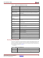
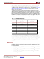
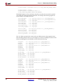
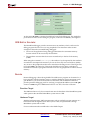
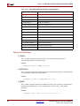
The following table shows the revision history for this document..
Version
Revision
06/24/02
1.0
Initial Xilinx EDK (Embedded Processor Development Kit) release.
08/13/02
1.1
EDK (v3.1) release.
09/02/03
1.3
EDK 6.1 release.
01/30/04
1.4
EDK 6.2i release
UG111 (v1.4) January 30, 2004
www.xilinx.com
1-800-255-7778
Embedded System Tools Guide
Embedded System Tools Guide
www.xilinx.com
1-800-255-7778
UG111 (v1.4) January 30, 2004
R
Preface
About This Guide
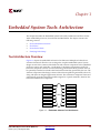
Welcome to the Embedded Developement Kit. This kit is designed to provide designers
with a rich set of design tools and a wide selection of standard peripherals required to
build embedded processor systems using MicroBlaze, the industry’s fastest soft processor
solution, and the new and unique feature in Virtex-II Pro, the IBM ® PowerPC ® CPU.
This guide provides information about the Embedded System Tools (EST) included in the
Embedded Development Kit (EDK). These tools, consisting of processor platform tailoring
utilities, software application development tool, a full featured debug tool chain and
device drivers and libraries, allow the developer to fully exploit the power of MicroBlaze
and Virtex-II Pro.
Guide Contents
This guide contains the following chapters:
x
Chapter 1, “Embedded System Tools Architecture”
x
Chapter 2, “Xilinx Platform Studio (XPS)”
x
Chapter 3, “Base System Builder”
x
Chapter 4, “Create/Import Peripheral Wizard”
x
Chapter 5, “Platform Generator”
x
Chapter 6, “Simulation Model Generator”
x
Chapter 7, “Library Generator”
x
Chapter 8, “Platform Specification Utility”
x
Chapter 9, “Format Revision Tool”
x
Chapter 10, “Bitstream Initializer”
x
Chapter 11, “GNU Compiler Tools”
x
Chapter 12, “GNU Debugger”
x
Chapter 13, “Xilinx Microprocessor Debugger (XMD)”
x
Chapter 14, “Platform Specification Format (PSF)”
x
Chapter 15, “Microprocessor Hardware Specification (MHS)”
x
Chapter 16, “Microprocessor Peripheral Description (MPD)”
x
Chapter 17, “Peripheral Analyze Order (PAO)”
x
Chapter 18, “Black-Box Definition (BBD)”
x
Chapter 19, “Microprocessor Software Specification (MSS)”
x
Chapter 20, “Microprocessor Library Definition (MLD)”
x
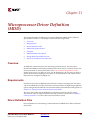
Chapter 21, “Microprocessor Driver Definition (MDD)”
Embedded System Tools Guide (EDK 6.2i)
UG111 (v1.4) January 30, 2004
www.xilinx.com
1-800-255-7778
5
R
Preface: About This Guide
x
Chapter 22, “Address Management”
x
Chapter 23, “Interrupt Management”
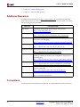
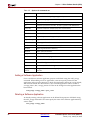
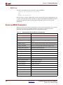
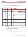
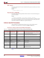
Additional Resources
For additional information, go to http://support.xilinx.com. The following table lists
some of the resources you can access from this website. You can also directly access these
resources using the provided URLs.
Resource
EDK Home
Description/URL
Embedded Development Kit home page, FAQ and tips.
http://www.xilinx.com/edk
EDK Examples
A set of complete EDK examples.
http://www.xilinx.com/ise/embedded/edk_examples.htm
Tutorials
Tutorials covering Xilinx design flows, from design entry to
verification and debugging
http://support.xilinx.com/support/techsup/tutorials/index.htm
Answer Browser
Database of Xilinx solution records
http://support.xilinx.com/xlnx/xil_ans_browser.jsp
Application Notes
Descriptions of device-specific design techniques and approaches
http://support.xilinx.com/apps/appsweb.htm
Data Sheets
Device-specific information on Xilinx device characteristics,
including readback, boundary scan, configuration, length count,
and debugging
http://support.xilinx.com/xlnx/xweb/xil_publications_index.jsp
Problem Solvers
Interactive tools that allow you to troubleshoot your design issues
http://support.xilinx.com/support/troubleshoot/psolvers.htm
Tech Tips
Latest news, design tips, and patch information for the Xilinx
design environment
http://www.support.xilinx.com/xlnx/xil_tt_home.jsp
GNU Manuals
The entire set of GNU manuals
http://www.gnu.org/manual
Conventions
This document uses the following conventions. An example illustrates each convention.
6
www.xilinx.com
1-800-255-7778
Embedded System Tools Guide (EDK 6.2i)
UG111 (v1.4) January 30, 2004
R
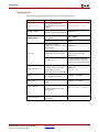
Conventions
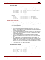
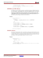
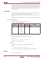
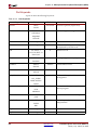
Typographical
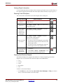
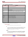
The following typographical conventions are used in this document:
Convention
Meaning or Use
Example
Courier font
Messages, prompts, and
program files that the system
displays
speed grade: - 100
Courier bold
Literal commands that you
enter in a syntactical statement
ngdbuild design_name
Commands that you select
from a menu
File o Open
Keyboard shortcuts
Ctrl+C
Variables in a syntax
statement for which you must
supply values
ngdbuild design_name
References to other manuals
See the Development System
Reference Guide for more
information.
Emphasis in text
If a wire is drawn so that it
overlaps the pin of a symbol,
the two nets are not connected.
Square brackets [ ]
An optional entry or
parameter. However, in bus
specifications, such as
bus[7:0], they are required.
ngdbuild [option_name]
design_name
Braces { }
A list of items from which you
must choose one or more
lowpwr ={on|off}
Separates items in a list of
choices
lowpwr ={on|off}
Vertical ellipsis
.
.
.
Repetitive material that has
been omitted
IOB #1: Name = QOUT’
IOB #2: Name = CLKIN’
.
.
.
Horizontal ellipsis . . .
Repetitive material that has
been omitted
allow block block_name
loc1 loc2 ... locn;
Helvetica bold
Italic font
Vertical bar
|
Embedded System Tools Guide (EDK 6.2i)
UG111 (v1.4) January 30, 2004
www.xilinx.com
1-800-255-7778
7
R
Preface: About This Guide
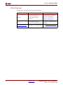
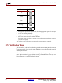
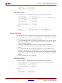
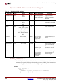
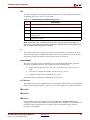
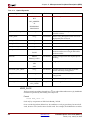
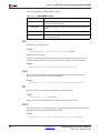
Online Document
The following conventions are used in this document:
Convention
8
Meaning or Use
Example
See the section “Additional
Resources” for details.
Blue text
Cross-reference link to a
location in the current
document
Red text
Cross-reference link to a
location in another document
See Figure 2-5 in the Virtex-II
Handbook.
Blue, underlined text
Hyperlink to a website (URL)
Go to http://www.xilinx.com
for the latest speed files.
www.xilinx.com
1-800-255-7778
Refer to “Title Formats” in
Chapter 1 for details.
Embedded System Tools Guide (EDK 6.2i)
UG111 (v1.4) January 30, 2004
Table of Contents
Preface: About This Guide
Guide Contents . . . . . . . . . . . . . . . . . . . . . . . . . . . . . . . . . . . . . . . . . . . . . . . . . . . . . . . . . . . . . . 5
Additional Resources . . . . . . . . . . . . . . . . . . . . . . . . . . . . . . . . . . . . . . . . . . . . . . . . . . . . . . . . 6
Conventions . . . . . . . . . . . . . . . . . . . . . . . . . . . . . . . . . . . . . . . . . . . . . . . . . . . . . . . . . . . . . . . . . 6
Typographical . . . . . . . . . . . . . . . . . . . . . . . . . . . . . . . . . . . . . . . . . . . . . . . . . . . . . . . . . . . . . 7
Online Document . . . . . . . . . . . . . . . . . . . . . . . . . . . . . . . . . . . . . . . . . . . . . . . . . . . . . . . . . . 8
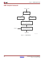
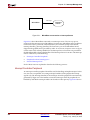
Chapter 1: Embedded System Tools Architecture
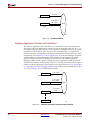
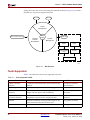
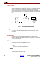
Tool Architecture Overview . . . . . . . . . . . . . . . . . . . . . . . . . . . . . . . . . . . . . . . . . . . . . . . . . 27
Tool Flows . . . . . . . . . . . . . . . . . . . . . . . . . . . . . . . . . . . . . . . . . . . . . . . . . . . . . . . . . . . . . . . . . . 28
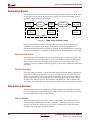
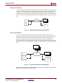
Hardware Platform Creation . . . . . . . . . . . . . . . . . . . . . . . . . . . . . . . . . . . . . . . . . . . . . . .
Verification Platform Creation . . . . . . . . . . . . . . . . . . . . . . . . . . . . . . . . . . . . . . . . . . . . . .
Software Platform Creation . . . . . . . . . . . . . . . . . . . . . . . . . . . . . . . . . . . . . . . . . . . . . . . .
Software Application Creation and Verification . . . . . . . . . . . . . . . . . . . . . . . . . . . . . . .
28
29
29
30
Some Useful Tools . . . . . . . . . . . . . . . . . . . . . . . . . . . . . . . . . . . . . . . . . . . . . . . . . . . . . . . . . . 31
Xilinx Platform Studio . . . . . . . . . . . . . . . . . . . . . . . . . . . . . . . . . . . . . . . . . . . . . . . . . . . . .
Platform Generator . . . . . . . . . . . . . . . . . . . . . . . . . . . . . . . . . . . . . . . . . . . . . . . . . . . . . . .
HDL Synthesis . . . . . . . . . . . . . . . . . . . . . . . . . . . . . . . . . . . . . . . . . . . . . . . . . . . . . . . . . . .
ISE XST . . . . . . . . . . . . . . . . . . . . . . . . . . . . . . . . . . . . . . . . . . . . . . . . . . . . . . . . . . . . . .
Simulation Model Generator . . . . . . . . . . . . . . . . . . . . . . . . . . . . . . . . . . . . . . . . . . . . . . .
Library Generator . . . . . . . . . . . . . . . . . . . . . . . . . . . . . . . . . . . . . . . . . . . . . . . . . . . . . . . .
GNU Compiler Tools . . . . . . . . . . . . . . . . . . . . . . . . . . . . . . . . . . . . . . . . . . . . . . . . . . . . . .
MicroBlaze . . . . . . . . . . . . . . . . . . . . . . . . . . . . . . . . . . . . . . . . . . . . . . . . . . . . . . . . . . .
PowerPC . . . . . . . . . . . . . . . . . . . . . . . . . . . . . . . . . . . . . . . . . . . . . . . . . . . . . . . . . . . . .
Compiling with Optimization. . . . . . . . . . . . . . . . . . . . . . . . . . . . . . . . . . . . . . . . . . . . .
Setting the Stack Size . . . . . . . . . . . . . . . . . . . . . . . . . . . . . . . . . . . . . . . . . . . . . . . . . . .
Software Debugging . . . . . . . . . . . . . . . . . . . . . . . . . . . . . . . . . . . . . . . . . . . . . . . . . . . . . .
Debugging Using Hardware: software intrusive . . . . . . . . . . . . . . . . . . . . . . . . . . . . . .
Debugging Using A Simulator: non-intrusive . . . . . . . . . . . . . . . . . . . . . . . . . . . . . . . .
Dumping an Object/Executable File . . . . . . . . . . . . . . . . . . . . . . . . . . . . . . . . . . . . . . . . .
31
31
31
31
31
31
32
32
32
32
32
32
33
33
34
Verifying Tools Setup . . . . . . . . . . . . . . . . . . . . . . . . . . . . . . . . . . . . . . . . . . . . . . . . . . . . . . . 34
Tools Directory Path . . . . . . . . . . . . . . . . . . . . . . . . . . . . . . . . . . . . . . . . . . . . . . . . . . . . . .
For Solaris . . . . . . . . . . . . . . . . . . . . . . . . . . . . . . . . . . . . . . . . . . . . . . . . . . . . . . . . . . . .
For PC . . . . . . . . . . . . . . . . . . . . . . . . . . . . . . . . . . . . . . . . . . . . . . . . . . . . . . . . . . . . . . .
Xilinx Alliance Software . . . . . . . . . . . . . . . . . . . . . . . . . . . . . . . . . . . . . . . . . . . . . . . . . . .
34
34
34
34
Chapter 2: Xilinx Platform Studio (XPS)
Processes Supported . . . . . . . . . . . . . . . . . . . . . . . . . . . . . . . . . . . . . . . . . . . . . . . . . . . . . . . . 35
Tools Supported . . . . . . . . . . . . . . . . . . . . . . . . . . . . . . . . . . . . . . . . . . . . . . . . . . . . . . . . . . . . 36
Features. . . . . . . . . . . . . . . . . . . . . . . . . . . . . . . . . . . . . . . . . . . . . . . . . . . . . . . . . . . . . . 37
Project Management . . . . . . . . . . . . . . . . . . . . . . . . . . . . . . . . . . . . . . . . . . . . . . . . . . . . . . . . 37
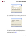
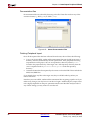
Creating A New Project . . . . . . . . . . . . . . . . . . . . . . . . . . . . . . . . . . . . . . . . . . . . . . . . . 37
Opening An Existing Project . . . . . . . . . . . . . . . . . . . . . . . . . . . . . . . . . . . . . . . . . . . . . . 38
Getting Help . . . . . . . . . . . . . . . . . . . . . . . . . . . . . . . . . . . . . . . . . . . . . . . . . . . . . . . . . . 38
Embedded System Tools Guide (EDK 6.2i)
UG111 (v1.4) January 30, 2004
www.xilinx.com
1-800-255-7778
9
R
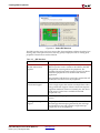
XPS Interface . . . . . . . . . . . . . . . . . . . . . . . . . . . . . . . . . . . . . . . . . . . . . . . . . . . . . . . . . . . . . . . 39
Editor Workspace . . . . . . . . . . . . . . . . . . . . . . . . . . . . . . . . . . . . . . . . . . . . . . . . . . . . . .
System Tab . . . . . . . . . . . . . . . . . . . . . . . . . . . . . . . . . . . . . . . . . . . . . . . . . . . . . . . . . . .
Applications Tab . . . . . . . . . . . . . . . . . . . . . . . . . . . . . . . . . . . . . . . . . . . . . . . . . . . . . . .
Transcript Window (Output) . . . . . . . . . . . . . . . . . . . . . . . . . . . . . . . . . . . . . . . . . . . . .
39
40
40
40
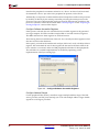
Platform Management. . . . . . . . . . . . . . . . . . . . . . . . . . . . . . . . . . . . . . . . . . . . . . . . . . . . . . . 41
Add/Edit Cores (Dialog) . . . . . . . . . . . . . . . . . . . . . . . . . . . . . . . . . . . . . . . . . . . . . . . . . .
Simulation Models . . . . . . . . . . . . . . . . . . . . . . . . . . . . . . . . . . . . . . . . . . . . . . . . . . . . . . . .
View MPD . . . . . . . . . . . . . . . . . . . . . . . . . . . . . . . . . . . . . . . . . . . . . . . . . . . . . . . . . . . . . . .
View MDD . . . . . . . . . . . . . . . . . . . . . . . . . . . . . . . . . . . . . . . . . . . . . . . . . . . . . . . . . . . . . .
S/W Settings . . . . . . . . . . . . . . . . . . . . . . . . . . . . . . . . . . . . . . . . . . . . . . . . . . . . . . . . . . . . .
Software Platform . . . . . . . . . . . . . . . . . . . . . . . . . . . . . . . . . . . . . . . . . . . . . . . . . . . . . .
Processor and Driver Parameters . . . . . . . . . . . . . . . . . . . . . . . . . . . . . . . . . . . . . . . . . .
Library and O/S Parameters. . . . . . . . . . . . . . . . . . . . . . . . . . . . . . . . . . . . . . . . . . . . . .
41
41
41
41
41
41
42
42
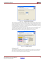
Software Application Management . . . . . . . . . . . . . . . . . . . . . . . . . . . . . . . . . . . . . . . . . . 42
Adding Files . . . . . . . . . . . . . . . . . . . . . . . . . . . . . . . . . . . . . . . . . . . . . . . . . . . . . . . . . .
Deleting Files from Project . . . . . . . . . . . . . . . . . . . . . . . . . . . . . . . . . . . . . . . . . . . . . . .
Editing Files . . . . . . . . . . . . . . . . . . . . . . . . . . . . . . . . . . . . . . . . . . . . . . . . . . . . . . . . . .
Mark Application for downloading to BRAMs. . . . . . . . . . . . . . . . . . . . . . . . . . . . . . . .
Application to be compiled outside XPS environment . . . . . . . . . . . . . . . . . . . . . . . . . .
Bootloop Software Applications . . . . . . . . . . . . . . . . . . . . . . . . . . . . . . . . . . . . . . . . . . .
Xmdstub Software Applications . . . . . . . . . . . . . . . . . . . . . . . . . . . . . . . . . . . . . . . . . . .
Compiler Options . . . . . . . . . . . . . . . . . . . . . . . . . . . . . . . . . . . . . . . . . . . . . . . . . . . . . .
42
42
43
43
43
43
43
44
Flow Tool Settings and Required Files . . . . . . . . . . . . . . . . . . . . . . . . . . . . . . . . . . . . . . . 45
Compiler Options . . . . . . . . . . . . . . . . . . . . . . . . . . . . . . . . . . . . . . . . . . . . . . . . . . . . . . 45
Project Options . . . . . . . . . . . . . . . . . . . . . . . . . . . . . . . . . . . . . . . . . . . . . . . . . . . . . . . . 45
Required Files . . . . . . . . . . . . . . . . . . . . . . . . . . . . . . . . . . . . . . . . . . . . . . . . . . . . . . . . . 47
Tool Invocation . . . . . . . . . . . . . . . . . . . . . . . . . . . . . . . . . . . . . . . . . . . . . . . . . . . . . . . . . . . . . 47
Software Flow . . . . . . . . . . . . . . . . . . . . . . . . . . . . . . . . . . . . . . . . . . . . . . . . . . . . . . . . .
Hardware Flow . . . . . . . . . . . . . . . . . . . . . . . . . . . . . . . . . . . . . . . . . . . . . . . . . . . . . . . .
Merging Hardware and Software Flows and Downloading . . . . . . . . . . . . . . . . . . . . . .
ISE Project Navigator Interface . . . . . . . . . . . . . . . . . . . . . . . . . . . . . . . . . . . . . . . . . . . .
47
47
48
48
Debug and Simulation . . . . . . . . . . . . . . . . . . . . . . . . . . . . . . . . . . . . . . . . . . . . . . . . . . . . . . 49
PBD Editor . . . . . . . . . . . . . . . . . . . . . . . . . . . . . . . . . . . . . . . . . . . . . . . . . . . . . . . . . . . . . . . . . . 49
PBD Editor Interface . . . . . . . . . . . . . . . . . . . . . . . . . . . . . . . . . . . . . . . . . . . . . . . . . . . . . .
PBD Editor Workspace . . . . . . . . . . . . . . . . . . . . . . . . . . . . . . . . . . . . . . . . . . . . . . . . . .
System Tabs . . . . . . . . . . . . . . . . . . . . . . . . . . . . . . . . . . . . . . . . . . . . . . . . . . . . . . . . . .
Creating the Hardware Block Diagram . . . . . . . . . . . . . . . . . . . . . . . . . . . . . . . . . . . . . .
Adding a Component Instance to the System . . . . . . . . . . . . . . . . . . . . . . . . . . . . . . . . .
Naming an Instance . . . . . . . . . . . . . . . . . . . . . . . . . . . . . . . . . . . . . . . . . . . . . . . . . . . .
Setting Component Instance Parameters . . . . . . . . . . . . . . . . . . . . . . . . . . . . . . . . . . . .
Setting Symbol Properties . . . . . . . . . . . . . . . . . . . . . . . . . . . . . . . . . . . . . . . . . . . . . . . .
Connecting a Component Bus Pin to a Bus . . . . . . . . . . . . . . . . . . . . . . . . . . . . . . . . . . .
Connecting Ports. . . . . . . . . . . . . . . . . . . . . . . . . . . . . . . . . . . . . . . . . . . . . . . . . . . . . . .
Viewing and Editing System Ports . . . . . . . . . . . . . . . . . . . . . . . . . . . . . . . . . . . . . . . . .
Viewing and Editing All of the Ports in the System . . . . . . . . . . . . . . . . . . . . . . . . . . . .
Viewing and Editing Interrupts . . . . . . . . . . . . . . . . . . . . . . . . . . . . . . . . . . . . . . . . . . .
Editing the Block Diagram . . . . . . . . . . . . . . . . . . . . . . . . . . . . . . . . . . . . . . . . . . . . . . . . .
Selecting Objects . . . . . . . . . . . . . . . . . . . . . . . . . . . . . . . . . . . . . . . . . . . . . . . . . . . . . . .
Viewing Object Information . . . . . . . . . . . . . . . . . . . . . . . . . . . . . . . . . . . . . . . . . . . . . .
Zooming in the Workspace . . . . . . . . . . . . . . . . . . . . . . . . . . . . . . . . . . . . . . . . . . . . . . .
Drawing Non-Electrical Objects . . . . . . . . . . . . . . . . . . . . . . . . . . . . . . . . . . . . . . . . . . .
10
www.xilinx.com
1-800-255-7778
49
50
51
51
51
52
52
53
53
54
54
55
55
56
56
57
57
57
Embedded System Tools Guide (EDK 6.2i)
UG111 (v1.4) January 30, 2004
R
XPS “No Window” Mode . . . . . . . . . . . . . . . . . . . . . . . . . . . . . . . . . . . . . . . . . . . . . . . . . . . 58
Available Commands . . . . . . . . . . . . . . . . . . . . . . . . . . . . . . . . . . . . . . . . . . . . . . . . . . . . .
Creating A New Empty Project . . . . . . . . . . . . . . . . . . . . . . . . . . . . . . . . . . . . . . . . . . . . .
Creating A New Project With Given MHS . . . . . . . . . . . . . . . . . . . . . . . . . . . . . . . . . . . .
Opening An Existing Project . . . . . . . . . . . . . . . . . . . . . . . . . . . . . . . . . . . . . . . . . . . . . . .
Reading MSS File . . . . . . . . . . . . . . . . . . . . . . . . . . . . . . . . . . . . . . . . . . . . . . . . . . . . . . . . .
Saving Files and Project . . . . . . . . . . . . . . . . . . . . . . . . . . . . . . . . . . . . . . . . . . . . . . . . . . .
Setting Project Options . . . . . . . . . . . . . . . . . . . . . . . . . . . . . . . . . . . . . . . . . . . . . . . . . . . .
Executing Flow Commands . . . . . . . . . . . . . . . . . . . . . . . . . . . . . . . . . . . . . . . . . . . . . . . .
Adding a Software Application . . . . . . . . . . . . . . . . . . . . . . . . . . . . . . . . . . . . . . . . . . . . .
Deleting a Software Application . . . . . . . . . . . . . . . . . . . . . . . . . . . . . . . . . . . . . . . . . . . .
Adding a Program File to a Software Application . . . . . . . . . . . . . . . . . . . . . . . . . . . . .
Deleting a Program File from a Software Application . . . . . . . . . . . . . . . . . . . . . . . . . .
Setting Options on a Software Application . . . . . . . . . . . . . . . . . . . . . . . . . . . . . . . . . . .
Closing A Project and Exiting . . . . . . . . . . . . . . . . . . . . . . . . . . . . . . . . . . . . . . . . . . . . . .
Limitations And Workarounds . . . . . . . . . . . . . . . . . . . . . . . . . . . . . . . . . . . . . . . . . . . . .
MSS Changes . . . . . . . . . . . . . . . . . . . . . . . . . . . . . . . . . . . . . . . . . . . . . . . . . . . . . . . . .
XMP Changes . . . . . . . . . . . . . . . . . . . . . . . . . . . . . . . . . . . . . . . . . . . . . . . . . . . . . . . . .
59
59
60
60
60
60
60
61
62
62
63
63
63
64
64
64
64
Chapter 3: Base System Builder
BSB Flow . . . . . . . . . . . . . . . . . . . . . . . . . . . . . . . . . . . . . . . . . . . . . . . . . . . . . . . . . . . . . . . . . . . 65
Invoking BSB . . . . . . . . . . . . . . . . . . . . . . . . . . . . . . . . . . . . . . . . . . . . . . . . . . . . . . . . . . . .
Selecting A Target Development Board . . . . . . . . . . . . . . . . . . . . . . . . . . . . . . . . . . . . . .
Selecting A Processor. . . . . . . . . . . . . . . . . . . . . . . . . . . . . . . . . . . . . . . . . . . . . . . . . . . . . .
Configuring Processor and System Settings . . . . . . . . . . . . . . . . . . . . . . . . . . . . . . . . . .
Selecting External Memories and I/O Devices . . . . . . . . . . . . . . . . . . . . . . . . . . . . . . . .
Adding Internal Peripherals . . . . . . . . . . . . . . . . . . . . . . . . . . . . . . . . . . . . . . . . . . . . . . . .
Configuring Software Settings . . . . . . . . . . . . . . . . . . . . . . . . . . . . . . . . . . . . . . . . . . . . . .
Generating the System and Address Map . . . . . . . . . . . . . . . . . . . . . . . . . . . . . . . . . . . .
Output Files . . . . . . . . . . . . . . . . . . . . . . . . . . . . . . . . . . . . . . . . . . . . . . . . . . . . . . . . . . . . .
Exiting BSB . . . . . . . . . . . . . . . . . . . . . . . . . . . . . . . . . . . . . . . . . . . . . . . . . . . . . . . . . . . . . .
65
66
67
68
69
70
71
72
73
74
Limitations . . . . . . . . . . . . . . . . . . . . . . . . . . . . . . . . . . . . . . . . . . . . . . . . . . . . . . . . . . . . . . . . . 75
Chapter 4: Create/Import Peripheral Wizard
Creating New Peripherals . . . . . . . . . . . . . . . . . . . . . . . . . . . . . . . . . . . . . . . . . . . . . . . . . . . 77
Identifying the Physical Location of your Peripheral . . . . . . . . . . . . . . . . . . . . . . . . . . .
Identifying Module and Version. . . . . . . . . . . . . . . . . . . . . . . . . . . . . . . . . . . . . . . . . . .
Select Bus Interface . . . . . . . . . . . . . . . . . . . . . . . . . . . . . . . . . . . . . . . . . . . . . . . . . . . . .
Select IPIF Services . . . . . . . . . . . . . . . . . . . . . . . . . . . . . . . . . . . . . . . . . . . . . . . . . . . . .
Review EDK Peripheral Design Flow . . . . . . . . . . . . . . . . . . . . . . . . . . . . . . . . . . . . . . .
Generating the files representing your peripheral . . . . . . . . . . . . . . . . . . . . . . . . . . . . .
78
79
80
80
86
87
Importing an Existing Peripheral . . . . . . . . . . . . . . . . . . . . . . . . . . . . . . . . . . . . . . . . . . . . 87
Identifying the Physical Location of your Peripheral . . . . . . . . . . . . . . . . . . . . . . . . . . .
Identifying Module and Version. . . . . . . . . . . . . . . . . . . . . . . . . . . . . . . . . . . . . . . . . . .
Select Source File Types . . . . . . . . . . . . . . . . . . . . . . . . . . . . . . . . . . . . . . . . . . . . . . . . .
HDL Source Files . . . . . . . . . . . . . . . . . . . . . . . . . . . . . . . . . . . . . . . . . . . . . . . . . . . . . .
HDL Analysis Information . . . . . . . . . . . . . . . . . . . . . . . . . . . . . . . . . . . . . . . . . . . . . . .
Bus Interfaces . . . . . . . . . . . . . . . . . . . . . . . . . . . . . . . . . . . . . . . . . . . . . . . . . . . . . . . . .
Identifying Bus Interface Ports and Parameters . . . . . . . . . . . . . . . . . . . . . . . . . . . . . . .
Interrupt Signals . . . . . . . . . . . . . . . . . . . . . . . . . . . . . . . . . . . . . . . . . . . . . . . . . . . . . . .
Advanced Attributes on Ports and Parameters . . . . . . . . . . . . . . . . . . . . . . . . . . . . . . . .
Embedded System Tools Guide (EDK 6.2i)
UG111 (v1.4) January 30, 2004
www.xilinx.com
1-800-255-7778
87
88
88
88
89
91
92
93
93
11
R
Netlist files . . . . . . . . . . . . . . . . . . . . . . . . . . . . . . . . . . . . . . . . . . . . . . . . . . . . . . . . . . . 95
Documentation files . . . . . . . . . . . . . . . . . . . . . . . . . . . . . . . . . . . . . . . . . . . . . . . . . . . . 96
Finishing Peripheral Import . . . . . . . . . . . . . . . . . . . . . . . . . . . . . . . . . . . . . . . . . . . . . . 96
Organization of generated files . . . . . . . . . . . . . . . . . . . . . . . . . . . . . . . . . . . . . . . . . . . . . . 97
Limitations . . . . . . . . . . . . . . . . . . . . . . . . . . . . . . . . . . . . . . . . . . . . . . . . . . . . . . . . . . . . . . . . . 98
Create Peripheral Mode . . . . . . . . . . . . . . . . . . . . . . . . . . . . . . . . . . . . . . . . . . . . . . . . . 98
Import Peripheral Mode . . . . . . . . . . . . . . . . . . . . . . . . . . . . . . . . . . . . . . . . . . . . . . . . . 98
Chapter 5: Platform Generator
Tool Requirements . . . . . . . . . . . . . . . . . . . . . . . . . . . . . . . . . . . . . . . . . . . . . . . . . . . . . . . . . . 99
Tool Usage . . . . . . . . . . . . . . . . . . . . . . . . . . . . . . . . . . . . . . . . . . . . . . . . . . . . . . . . . . . . . . . . . . 99
Tool Options . . . . . . . . . . . . . . . . . . . . . . . . . . . . . . . . . . . . . . . . . . . . . . . . . . . . . . . . . . . . . . . 100
Load Path . . . . . . . . . . . . . . . . . . . . . . . . . . . . . . . . . . . . . . . . . . . . . . . . . . . . . . . . . . . . . . . . . . 101
Output Files . . . . . . . . . . . . . . . . . . . . . . . . . . . . . . . . . . . . . . . . . . . . . . . . . . . . . . . . . . . . . . . 101
HDL Directory . . . . . . . . . . . . . . . . . . . . . . . . . . . . . . . . . . . . . . . . . . . . . . . . . . . . . . . . . . 101
Implementation Directory . . . . . . . . . . . . . . . . . . . . . . . . . . . . . . . . . . . . . . . . . . . . . . . . 102
Synthesis Directory . . . . . . . . . . . . . . . . . . . . . . . . . . . . . . . . . . . . . . . . . . . . . . . . . . . . . . 102
About Memory Generation . . . . . . . . . . . . . . . . . . . . . . . . . . . . . . . . . . . . . . . . . . . . . . . . . 102
BMM Policy . . . . . . . . . . . . . . . . . . . . . . . . . . . . . . . . . . . . . . . . . . . . . . . . . . . . . . . . . . . . . 103
BMM Flow . . . . . . . . . . . . . . . . . . . . . . . . . . . . . . . . . . . . . . . . . . . . . . . . . . . . . . . . . . . . . . 104
Reserved MHS Parameters . . . . . . . . . . . . . . . . . . . . . . . . . . . . . . . . . . . . . . . . . . . . . . . . . 104
Synthesis Netlist Cache . . . . . . . . . . . . . . . . . . . . . . . . . . . . . . . . . . . . . . . . . . . . . . . . . . . . 105
Current Limitations . . . . . . . . . . . . . . . . . . . . . . . . . . . . . . . . . . . . . . . . . . . . . . . . . . . . . . . . 105
Chapter 6: Simulation Model Generator
Overview . . . . . . . . . . . . . . . . . . . . . . . . . . . . . . . . . . . . . . . . . . . . . . . . . . . . . . . . . . . . . . . . . . 107
Simulation Basics . . . . . . . . . . . . . . . . . . . . . . . . . . . . . . . . . . . . . . . . . . . . . . . . . . . . . . . . . . 108
Structural Simulation . . . . . . . . . . . . . . . . . . . . . . . . . . . . . . . . . . . . . . . . . . . . . . . . . . . . . 108
Timing Simulation . . . . . . . . . . . . . . . . . . . . . . . . . . . . . . . . . . . . . . . . . . . . . . . . . . . . . . . 108
Simulation Libraries . . . . . . . . . . . . . . . . . . . . . . . . . . . . . . . . . . . . . . . . . . . . . . . . . . . . . . . 108
Xilinx Libraries . . . . . . . . . . . . . . . . . . . . . . . . . . . . . . . . . . . . . . . . . . . . . . . . . . . . . . . . . .
UNISIM Library . . . . . . . . . . . . . . . . . . . . . . . . . . . . . . . . . . . . . . . . . . . . . . . . . . . . . .
SIMPRIM Library . . . . . . . . . . . . . . . . . . . . . . . . . . . . . . . . . . . . . . . . . . . . . . . . . . . . .
XilinxCoreLib Library . . . . . . . . . . . . . . . . . . . . . . . . . . . . . . . . . . . . . . . . . . . . . . . . . .
EDK Library . . . . . . . . . . . . . . . . . . . . . . . . . . . . . . . . . . . . . . . . . . . . . . . . . . . . . . . . . . . .
108
109
109
109
109
Compiling EDK Simulation Libraries . . . . . . . . . . . . . . . . . . . . . . . . . . . . . . . . . . . . . . 109
Usage . . . . . . . . . . . . . . . . . . . . . . . . . . . . . . . . . . . . . . . . . . . . . . . . . . . . . . . . . . . . . . . . . .
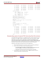
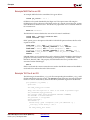
COMPEDKLIB Command Line Examples . . . . . . . . . . . . . . . . . . . . . . . . . . . . . . . . . . .
Use Case I: Compiling HDL sources in the built-in repositories in the EDK . . . . . . . .
Use Case II: Compiling HDL sources in your own repository . . . . . . . . . . . . . . . . . . .
Other details . . . . . . . . . . . . . . . . . . . . . . . . . . . . . . . . . . . . . . . . . . . . . . . . . . . . . . . . . . . .
109
110
110
110
110
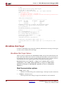
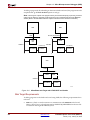
Simulation Models . . . . . . . . . . . . . . . . . . . . . . . . . . . . . . . . . . . . . . . . . . . . . . . . . . . . . . . . . 110
Behavioral Models . . . . . . . . . . . . . . . . . . . . . . . . . . . . . . . . . . . . . . . . . . . . . . . . . . . . . . . 111
Structural Models . . . . . . . . . . . . . . . . . . . . . . . . . . . . . . . . . . . . . . . . . . . . . . . . . . . . . . . . 111
Timing Models . . . . . . . . . . . . . . . . . . . . . . . . . . . . . . . . . . . . . . . . . . . . . . . . . . . . . . . . . . 112
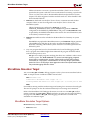
SimGen Syntax . . . . . . . . . . . . . . . . . . . . . . . . . . . . . . . . . . . . . . . . . . . . . . . . . . . . . . . . . . . . 112
Requirements . . . . . . . . . . . . . . . . . . . . . . . . . . . . . . . . . . . . . . . . . . . . . . . . . . . . . . . . . . . 112
Options . . . . . . . . . . . . . . . . . . . . . . . . . . . . . . . . . . . . . . . . . . . . . . . . . . . . . . . . . . . . . . . . 112
12
www.xilinx.com
1-800-255-7778
Embedded System Tools Guide (EDK 6.2i)
UG111 (v1.4) January 30, 2004
R
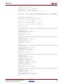
Help . . . . . . . . . . . . . . . . . . . . . . . . . . . . . . . . . . . . . . . . . . . . . . . . . . . . . . . . . . . . . . .
Version . . . . . . . . . . . . . . . . . . . . . . . . . . . . . . . . . . . . . . . . . . . . . . . . . . . . . . . . . . . . .
Options file . . . . . . . . . . . . . . . . . . . . . . . . . . . . . . . . . . . . . . . . . . . . . . . . . . . . . . . . .
HDL Language . . . . . . . . . . . . . . . . . . . . . . . . . . . . . . . . . . . . . . . . . . . . . . . . . . . . . . .
Log output . . . . . . . . . . . . . . . . . . . . . . . . . . . . . . . . . . . . . . . . . . . . . . . . . . . . . . . . . .
Library Directories . . . . . . . . . . . . . . . . . . . . . . . . . . . . . . . . . . . . . . . . . . . . . . . . . . . .
Simulation model type . . . . . . . . . . . . . . . . . . . . . . . . . . . . . . . . . . . . . . . . . . . . . . . .
Output Directory . . . . . . . . . . . . . . . . . . . . . . . . . . . . . . . . . . . . . . . . . . . . . . . . . . . . .
Target part or family . . . . . . . . . . . . . . . . . . . . . . . . . . . . . . . . . . . . . . . . . . . . . . . . . .
Processor Elf Files . . . . . . . . . . . . . . . . . . . . . . . . . . . . . . . . . . . . . . . . . . . . . . . . . . . .
Simulator . . . . . . . . . . . . . . . . . . . . . . . . . . . . . . . . . . . . . . . . . . . . . . . . . . . . . . . . . . .
Source Directory . . . . . . . . . . . . . . . . . . . . . . . . . . . . . . . . . . . . . . . . . . . . . . . . . . . . .
Top-level Instance . . . . . . . . . . . . . . . . . . . . . . . . . . . . . . . . . . . . . . . . . . . . . . . . . . . . .
Top-level Module . . . . . . . . . . . . . . . . . . . . . . . . . . . . . . . . . . . . . . . . . . . . . . . . . . . . .
Top-level . . . . . . . . . . . . . . . . . . . . . . . . . . . . . . . . . . . . . . . . . . . . . . . . . . . . . . . . . . . .
EDK Library Directory . . . . . . . . . . . . . . . . . . . . . . . . . . . . . . . . . . . . . . . . . . . . . . . .
Xilinx Library Directory. . . . . . . . . . . . . . . . . . . . . . . . . . . . . . . . . . . . . . . . . . . . . . . .
112
112
113
113
113
113
113
113
113
113
114
114
114
114
114
114
114
Output Files . . . . . . . . . . . . . . . . . . . . . . . . . . . . . . . . . . . . . . . . . . . . . . . . . . . . . . . . . . . . . . . 114
Memory Initialization . . . . . . . . . . . . . . . . . . . . . . . . . . . . . . . . . . . . . . . . . . . . . . . . . . . . . . 115
VHDL . . . . . . . . . . . . . . . . . . . . . . . . . . . . . . . . . . . . . . . . . . . . . . . . . . . . . . . . . . . . . . . . . . 115
Verilog . . . . . . . . . . . . . . . . . . . . . . . . . . . . . . . . . . . . . . . . . . . . . . . . . . . . . . . . . . . . . . . . . 115
Simulating Your Design . . . . . . . . . . . . . . . . . . . . . . . . . . . . . . . . . . . . . . . . . . . . . . . . . . . . 115
Current Limitations . . . . . . . . . . . . . . . . . . . . . . . . . . . . . . . . . . . . . . . . . . . . . . . . . . . . . . . . 116
Chapter 7: Library Generator
Overview . . . . . . . . . . . . . . . . . . . . . . . . . . . . . . . . . . . . . . . . . . . . . . . . . . . . . . . . . . . . . . . . . . 117
Tool Usage . . . . . . . . . . . . . . . . . . . . . . . . . . . . . . . . . . . . . . . . . . . . . . . . . . . . . . . . . . . . . . . . . 117
Tool Options . . . . . . . . . . . . . . . . . . . . . . . . . . . . . . . . . . . . . . . . . . . . . . . . . . . . . . . . . . . . . . . 118
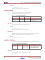
-h, -help (Help) . . . . . . . . . . . . . . . . . . . . . . . . . . . . . . . . . . . . . . . . . . . . . . . . . . . . . . .
-v (display version information) . . . . . . . . . . . . . . . . . . . . . . . . . . . . . . . . . . . . . . . . . .
-log logfile[.log] . . . . . . . . . . . . . . . . . . . . . . . . . . . . . . . . . . . . . . . . . . . . . . . . . . . . . .
-p family_name (architecture family) . . . . . . . . . . . . . . . . . . . . . . . . . . . . . . . . . . . . . .
-od output_dir (specify output directory) . . . . . . . . . . . . . . . . . . . . . . . . . . . . . . . . . . .
-sd source_dir (specify source directory) . . . . . . . . . . . . . . . . . . . . . . . . . . . . . . . . . . .
-lp library_path (specify library path for user peripherals and drivers repositories) . .
-mhs mhsfile.mhs (specify MHS file to be used) . . . . . . . . . . . . . . . . . . . . . . . . . . . . . .
-mode . . . . . . . . . . . . . . . . . . . . . . . . . . . . . . . . . . . . . . . . . . . . . . . . . . . . . . . . . . . . . .
-xmdstub proc_inst_name . . . . . . . . . . . . . . . . . . . . . . . . . . . . . . . . . . . . . . . . . . . . . .
-executable proc_inst_name . . . . . . . . . . . . . . . . . . . . . . . . . . . . . . . . . . . . . . . . . . . . .
-lib . . . . . . . . . . . . . . . . . . . . . . . . . . . . . . . . . . . . . . . . . . . . . . . . . . . . . . . . . . . . . . . .
-stub . . . . . . . . . . . . . . . . . . . . . . . . . . . . . . . . . . . . . . . . . . . . . . . . . . . . . . . . . . . . . . .
118
118
118
118
118
118
118
118
119
119
119
119
119
Load Path . . . . . . . . . . . . . . . . . . . . . . . . . . . . . . . . . . . . . . . . . . . . . . . . . . . . . . . . . . . . . . . . . . 120
Output Files . . . . . . . . . . . . . . . . . . . . . . . . . . . . . . . . . . . . . . . . . . . . . . . . . . . . . . . . . . . . . . . 122
include directory . . . . . . . . . . . . . . . . . . . . . . . . . . . . . . . . . . . . . . . . . . . . . . . . . . . . . . . .
lib directory . . . . . . . . . . . . . . . . . . . . . . . . . . . . . . . . . . . . . . . . . . . . . . . . . . . . . . . . . . . . .
libsrc directory . . . . . . . . . . . . . . . . . . . . . . . . . . . . . . . . . . . . . . . . . . . . . . . . . . . . . . . . . .
code directory . . . . . . . . . . . . . . . . . . . . . . . . . . . . . . . . . . . . . . . . . . . . . . . . . . . . . . . . . . .
122
122
122
123
Libraries and Drivers Generation . . . . . . . . . . . . . . . . . . . . . . . . . . . . . . . . . . . . . . . . . . . 123
MDD/MLD and Tcl . . . . . . . . . . . . . . . . . . . . . . . . . . . . . . . . . . . . . . . . . . . . . . . . . . . . . . 123
MSS Parameters. . . . . . . . . . . . . . . . . . . . . . . . . . . . . . . . . . . . . . . . . . . . . . . . . . . . . . . . . . . . 124
Embedded System Tools Guide (EDK 6.2i)
UG111 (v1.4) January 30, 2004
www.xilinx.com
1-800-255-7778
13
R
Drivers. . . . . . . . . . . . . . . . . . . . . . . . . . . . . . . . . . . . . . . . . . . . . . . . . . . . . . . . . . . . . . . . . . . . .
Libraries . . . . . . . . . . . . . . . . . . . . . . . . . . . . . . . . . . . . . . . . . . . . . . . . . . . . . . . . . . . . . . . . . . .
OS . . . . . . . . . . . . . . . . . . . . . . . . . . . . . . . . . . . . . . . . . . . . . . . . . . . . . . . . . . . . . . . . . . . . . . . . .
Interrupts and Interrupt Controller . . . . . . . . . . . . . . . . . . . . . . . . . . . . . . . . . . . . . . . . .
124
124
125
125
Interrupt Controller Driver Customization. . . . . . . . . . . . . . . . . . . . . . . . . . . . . . . . . . 125
XMDSTUB Peripherals (MicroBlaze Specific) . . . . . . . . . . . . . . . . . . . . . . . . . . . . . . 126
STDIN and STDOUT Peripherals . . . . . . . . . . . . . . . . . . . . . . . . . . . . . . . . . . . . . . . . . . 126
Chapter 8: Platform Specification Utility
Tool Options . . . . . . . . . . . . . . . . . . . . . . . . . . . . . . . . . . . . . . . . . . . . . . . . . . . . . . . . . . . . . . . 127
Overview of the MPD Creation Process . . . . . . . . . . . . . . . . . . . . . . . . . . . . . . . . . . . . . 128
Detailed Use Models for Automatic MPD Creation . . . . . . . . . . . . . . . . . . . . . . . . . 128
Peripherals with a Single Bus Interface . . . . . . . . . . . . . . . . . . . . . . . . . . . . . . . . . . . . .
Signal Naming Conventions . . . . . . . . . . . . . . . . . . . . . . . . . . . . . . . . . . . . . . . . . . . . .
Invoking PsfUtility . . . . . . . . . . . . . . . . . . . . . . . . . . . . . . . . . . . . . . . . . . . . . . . . . . . .
Peripherals with Multiple Bus Interfaces . . . . . . . . . . . . . . . . . . . . . . . . . . . . . . . . . . . .
Non-Exclusive Bus Interfaces . . . . . . . . . . . . . . . . . . . . . . . . . . . . . . . . . . . . . . . . . . . .
Exclusive Bus Interfaces . . . . . . . . . . . . . . . . . . . . . . . . . . . . . . . . . . . . . . . . . . . . . . . .
Peripherals with TRANSPARENT Bus Interfaces . . . . . . . . . . . . . . . . . . . . . . . . . . . .
BRAM PORTS . . . . . . . . . . . . . . . . . . . . . . . . . . . . . . . . . . . . . . . . . . . . . . . . . . . . . . . .
129
129
129
129
130
130
130
130
About Specification of VHDL Attributes . . . . . . . . . . . . . . . . . . . . . . . . . . . . . . . . . . . 131
Global IP Core Options . . . . . . . . . . . . . . . . . . . . . . . . . . . . . . . . . . . . . . . . . . . . . . . . . . . 131
IMP_NETLIST. . . . . . . . . . . . . . . . . . . . . . . . . . . . . . . . . . . . . . . . . . . . . . . . . . . . . . . . 131
IPTYPE . . . . . . . . . . . . . . . . . . . . . . . . . . . . . . . . . . . . . . . . . . . . . . . . . . . . . . . . . . . . . 131
When not specified as an attribute, the IPTYPE core option is automatically created by PsfUtility
with a value “PERIPHERAL”. . . . . . . . . . . . . . . . . . . . . . . . . . . . . . . . . . . . . . . . . . 131
IP_GROUP (User MUST specify) . . . . . . . . . . . . . . . . . . . . . . . . . . . . . . . . . . . . . . . . . 131
HDL . . . . . . . . . . . . . . . . . . . . . . . . . . . . . . . . . . . . . . . . . . . . . . . . . . . . . . . . . . . . . . . 131
SPECIAL (User MUST specify if required) . . . . . . . . . . . . . . . . . . . . . . . . . . . . . . . . . . 131
ALERT (User MUST specify if required) . . . . . . . . . . . . . . . . . . . . . . . . . . . . . . . . . . . 131
PAY_CORE (User MUST specify if required) . . . . . . . . . . . . . . . . . . . . . . . . . . . . . . . . 131
RUN_NGCBUILD (User MUST specify if required) . . . . . . . . . . . . . . . . . . . . . . . . . . . 131
Properties on Ports . . . . . . . . . . . . . . . . . . . . . . . . . . . . . . . . . . . . . . . . . . . . . . . . . . . . . . .
Port Value . . . . . . . . . . . . . . . . . . . . . . . . . . . . . . . . . . . . . . . . . . . . . . . . . . . . . . . . . . .
DIR . . . . . . . . . . . . . . . . . . . . . . . . . . . . . . . . . . . . . . . . . . . . . . . . . . . . . . . . . . . . . . . .
VEC . . . . . . . . . . . . . . . . . . . . . . . . . . . . . . . . . . . . . . . . . . . . . . . . . . . . . . . . . . . . . . . .
BUSIF . . . . . . . . . . . . . . . . . . . . . . . . . . . . . . . . . . . . . . . . . . . . . . . . . . . . . . . . . . . . . .
SIGIS (User MUST Specify) . . . . . . . . . . . . . . . . . . . . . . . . . . . . . . . . . . . . . . . . . . . . . .
IOB_STATE (User MUST Specify) . . . . . . . . . . . . . . . . . . . . . . . . . . . . . . . . . . . . . . . .
THREE_STATE . . . . . . . . . . . . . . . . . . . . . . . . . . . . . . . . . . . . . . . . . . . . . . . . . . . . . . .
ENDIAN (User MUST specify) . . . . . . . . . . . . . . . . . . . . . . . . . . . . . . . . . . . . . . . . . . .
Properties on Parameters . . . . . . . . . . . . . . . . . . . . . . . . . . . . . . . . . . . . . . . . . . . . . . . . .
MIN_SIZE (for Address parameter - User MUST specify) . . . . . . . . . . . . . . . . . . . . . .
ADDRESS and PAIR (for address parameter) . . . . . . . . . . . . . . . . . . . . . . . . . . . . . . .
BUS (for address parameter) . . . . . . . . . . . . . . . . . . . . . . . . . . . . . . . . . . . . . . . . . . . . .
XRANGE (to perform DRC’s on parameter values - User MUST specify) . . . . . . . . . .
132
132
132
132
132
132
132
132
132
133
133
133
133
133
DRC Checks in PsfUtility . . . . . . . . . . . . . . . . . . . . . . . . . . . . . . . . . . . . . . . . . . . . . . . . . . 133
HDL Source Errors . . . . . . . . . . . . . . . . . . . . . . . . . . . . . . . . . . . . . . . . . . . . . . . . . . . . . . . 133
Attribute Specification Errors. . . . . . . . . . . . . . . . . . . . . . . . . . . . . . . . . . . . . . . . . . . . . . 133
Bus Interface Checks . . . . . . . . . . . . . . . . . . . . . . . . . . . . . . . . . . . . . . . . . . . . . . . . . . . . . 133
14
www.xilinx.com
1-800-255-7778
Embedded System Tools Guide (EDK 6.2i)
UG111 (v1.4) January 30, 2004
R
Verilog Language Support . . . . . . . . . . . . . . . . . . . . . . . . . . . . . . . . . . . . . . . . . . . . . . . . . 134
VHDL Peripheral Definitions . . . . . . . . . . . . . . . . . . . . . . . . . . . . . . . . . . . . . . . . . . . . . . 134
VHDL Syntax . . . . . . . . . . . . . . . . . . . . . . . . . . . . . . . . . . . . . . . . . . . . . . . . . . . . . . . . . . .
Comments . . . . . . . . . . . . . . . . . . . . . . . . . . . . . . . . . . . . . . . . . . . . . . . . . . . . . . . . . . .
Format. . . . . . . . . . . . . . . . . . . . . . . . . . . . . . . . . . . . . . . . . . . . . . . . . . . . . . . . . . . . . .
Bus Interface Naming Conventions . . . . . . . . . . . . . . . . . . . . . . . . . . . . . . . . . . . . . . . .
Naming Conventions for VHDL Generics . . . . . . . . . . . . . . . . . . . . . . . . . . . . . . . . . . .
Reserved Parameters . . . . . . . . . . . . . . . . . . . . . . . . . . . . . . . . . . . . . . . . . . . . . . . . . . . . .
C_BUS_CONFIG . . . . . . . . . . . . . . . . . . . . . . . . . . . . . . . . . . . . . . . . . . . . . . . . . . . . . .
C_FAMILY . . . . . . . . . . . . . . . . . . . . . . . . . . . . . . . . . . . . . . . . . . . . . . . . . . . . . . . . . .
C_INSTANCE . . . . . . . . . . . . . . . . . . . . . . . . . . . . . . . . . . . . . . . . . . . . . . . . . . . . . . . .
C_OPB_NUM_MASTERS . . . . . . . . . . . . . . . . . . . . . . . . . . . . . . . . . . . . . . . . . . . . . . .
C_OPB_NUM_SLAVES . . . . . . . . . . . . . . . . . . . . . . . . . . . . . . . . . . . . . . . . . . . . . . . .
C_DCR_AWIDTH. . . . . . . . . . . . . . . . . . . . . . . . . . . . . . . . . . . . . . . . . . . . . . . . . . . . .
C_DCR_DWIDTH . . . . . . . . . . . . . . . . . . . . . . . . . . . . . . . . . . . . . . . . . . . . . . . . . . . . .
C_DCR_NUM_SLAVES . . . . . . . . . . . . . . . . . . . . . . . . . . . . . . . . . . . . . . . . . . . . . . . .
C_LMB_AWIDTH. . . . . . . . . . . . . . . . . . . . . . . . . . . . . . . . . . . . . . . . . . . . . . . . . . . . .
C_LMB_DWIDTH. . . . . . . . . . . . . . . . . . . . . . . . . . . . . . . . . . . . . . . . . . . . . . . . . . . . .
C_LMB_NUM_SLAVES . . . . . . . . . . . . . . . . . . . . . . . . . . . . . . . . . . . . . . . . . . . . . . . .
C_OPB_AWIDTH . . . . . . . . . . . . . . . . . . . . . . . . . . . . . . . . . . . . . . . . . . . . . . . . . . . . .
C_OPB_DWIDTH . . . . . . . . . . . . . . . . . . . . . . . . . . . . . . . . . . . . . . . . . . . . . . . . . . . . .
C_OPB_NUM_MASTERS . . . . . . . . . . . . . . . . . . . . . . . . . . . . . . . . . . . . . . . . . . . . . . .
C_OPB_NUM_SLAVES . . . . . . . . . . . . . . . . . . . . . . . . . . . . . . . . . . . . . . . . . . . . . . . .
C_PLB_AWIDTH . . . . . . . . . . . . . . . . . . . . . . . . . . . . . . . . . . . . . . . . . . . . . . . . . . . . .
C_PLB_DWIDTH . . . . . . . . . . . . . . . . . . . . . . . . . . . . . . . . . . . . . . . . . . . . . . . . . . . . .
C_PLB_MID_WIDTH . . . . . . . . . . . . . . . . . . . . . . . . . . . . . . . . . . . . . . . . . . . . . . . . . .
C_PLB_NUM_MASTERS . . . . . . . . . . . . . . . . . . . . . . . . . . . . . . . . . . . . . . . . . . . . . . .
C_PLB_NUM_SLAVES . . . . . . . . . . . . . . . . . . . . . . . . . . . . . . . . . . . . . . . . . . . . . . . . .
Signal Naming Conventions . . . . . . . . . . . . . . . . . . . . . . . . . . . . . . . . . . . . . . . . . . . . . .
Global Ports . . . . . . . . . . . . . . . . . . . . . . . . . . . . . . . . . . . . . . . . . . . . . . . . . . . . . . . . . . . . .
LMB - Clock and Reset . . . . . . . . . . . . . . . . . . . . . . . . . . . . . . . . . . . . . . . . . . . . . . . . .
OPB - Clock and Reset . . . . . . . . . . . . . . . . . . . . . . . . . . . . . . . . . . . . . . . . . . . . . . . . .
PLB - Clock and Reset . . . . . . . . . . . . . . . . . . . . . . . . . . . . . . . . . . . . . . . . . . . . . . . . . .
Slave DCR Ports . . . . . . . . . . . . . . . . . . . . . . . . . . . . . . . . . . . . . . . . . . . . . . . . . . . . . . . . .
DCR Slave Outputs . . . . . . . . . . . . . . . . . . . . . . . . . . . . . . . . . . . . . . . . . . . . . . . . . . . .
DCR Slave Inputs . . . . . . . . . . . . . . . . . . . . . . . . . . . . . . . . . . . . . . . . . . . . . . . . . . . . .
Slave LMB Ports . . . . . . . . . . . . . . . . . . . . . . . . . . . . . . . . . . . . . . . . . . . . . . . . . . . . . . . . .
LMB Slave Outputs . . . . . . . . . . . . . . . . . . . . . . . . . . . . . . . . . . . . . . . . . . . . . . . . . . . .
LMB Slave Inputs . . . . . . . . . . . . . . . . . . . . . . . . . . . . . . . . . . . . . . . . . . . . . . . . . . . . .
Master OPB Ports . . . . . . . . . . . . . . . . . . . . . . . . . . . . . . . . . . . . . . . . . . . . . . . . . . . . . . . .
OPB Master Outputs . . . . . . . . . . . . . . . . . . . . . . . . . . . . . . . . . . . . . . . . . . . . . . . . . . .
OPB Master Inputs . . . . . . . . . . . . . . . . . . . . . . . . . . . . . . . . . . . . . . . . . . . . . . . . . . . .
Slave OPB Ports . . . . . . . . . . . . . . . . . . . . . . . . . . . . . . . . . . . . . . . . . . . . . . . . . . . . . . . . .
OPB Slave Outputs . . . . . . . . . . . . . . . . . . . . . . . . . . . . . . . . . . . . . . . . . . . . . . . . . . . .
OPB Slave Inputs . . . . . . . . . . . . . . . . . . . . . . . . . . . . . . . . . . . . . . . . . . . . . . . . . . . . .
Master/Slave OPB Ports . . . . . . . . . . . . . . . . . . . . . . . . . . . . . . . . . . . . . . . . . . . . . . . . . .
OPB Master/Slave Outputs . . . . . . . . . . . . . . . . . . . . . . . . . . . . . . . . . . . . . . . . . . . . .
OPB Master/Slave Inputs . . . . . . . . . . . . . . . . . . . . . . . . . . . . . . . . . . . . . . . . . . . . . . .
Master PLB Ports . . . . . . . . . . . . . . . . . . . . . . . . . . . . . . . . . . . . . . . . . . . . . . . . . . . . . . . .
PLB Master Outputs . . . . . . . . . . . . . . . . . . . . . . . . . . . . . . . . . . . . . . . . . . . . . . . . . . .
PLB Master Inputs . . . . . . . . . . . . . . . . . . . . . . . . . . . . . . . . . . . . . . . . . . . . . . . . . . . .
Slave PLB Ports . . . . . . . . . . . . . . . . . . . . . . . . . . . . . . . . . . . . . . . . . . . . . . . . . . . . . . . . . .
PLB Slave Outputs . . . . . . . . . . . . . . . . . . . . . . . . . . . . . . . . . . . . . . . . . . . . . . . . . . . .
Embedded System Tools Guide (EDK 6.2i)
UG111 (v1.4) January 30, 2004
www.xilinx.com
1-800-255-7778
134
134
134
134
135
136
136
137
137
137
137
137
137
137
137
137
137
137
138
138
138
138
138
138
138
138
138
139
139
139
139
139
140
140
140
140
141
141
141
142
142
142
143
143
143
144
144
144
145
145
146
15
R
PLB Slave Inputs . . . . . . . . . . . . . . . . . . . . . . . . . . . . . . . . . . . . . . . . . . . . . . . . . . . . . .
Entity-level VHDL Attributes for Automation Support . . . . . . . . . . . . . . . . . . . . . . .
ADDR_SLICE Attribute . . . . . . . . . . . . . . . . . . . . . . . . . . . . . . . . . . . . . . . . . . . . . . . . . .
Format. . . . . . . . . . . . . . . . . . . . . . . . . . . . . . . . . . . . . . . . . . . . . . . . . . . . . . . . . . . . . .
AWIDTH Attribute . . . . . . . . . . . . . . . . . . . . . . . . . . . . . . . . . . . . . . . . . . . . . . . . . . . . . .
Format. . . . . . . . . . . . . . . . . . . . . . . . . . . . . . . . . . . . . . . . . . . . . . . . . . . . . . . . . . . . . .
ALERT Attribute . . . . . . . . . . . . . . . . . . . . . . . . . . . . . . . . . . . . . . . . . . . . . . . . . . . . . . . .
Format. . . . . . . . . . . . . . . . . . . . . . . . . . . . . . . . . . . . . . . . . . . . . . . . . . . . . . . . . . . . . .
BUSID Attribute . . . . . . . . . . . . . . . . . . . . . . . . . . . . . . . . . . . . . . . . . . . . . . . . . . . . . . . . .
Format. . . . . . . . . . . . . . . . . . . . . . . . . . . . . . . . . . . . . . . . . . . . . . . . . . . . . . . . . . . . . .
CORE_STATE Attribute . . . . . . . . . . . . . . . . . . . . . . . . . . . . . . . . . . . . . . . . . . . . . . . . . .
Format. . . . . . . . . . . . . . . . . . . . . . . . . . . . . . . . . . . . . . . . . . . . . . . . . . . . . . . . . . . . . .
DWIDTH Attribute . . . . . . . . . . . . . . . . . . . . . . . . . . . . . . . . . . . . . . . . . . . . . . . . . . . . . .
Format. . . . . . . . . . . . . . . . . . . . . . . . . . . . . . . . . . . . . . . . . . . . . . . . . . . . . . . . . . . . . .
HDL Attribute . . . . . . . . . . . . . . . . . . . . . . . . . . . . . . . . . . . . . . . . . . . . . . . . . . . . . . . . . .
Format. . . . . . . . . . . . . . . . . . . . . . . . . . . . . . . . . . . . . . . . . . . . . . . . . . . . . . . . . . . . . .
IMP_NETLIST Attribute . . . . . . . . . . . . . . . . . . . . . . . . . . . . . . . . . . . . . . . . . . . . . . . . . .
Format. . . . . . . . . . . . . . . . . . . . . . . . . . . . . . . . . . . . . . . . . . . . . . . . . . . . . . . . . . . . . .
IPTYPE Attribute . . . . . . . . . . . . . . . . . . . . . . . . . . . . . . . . . . . . . . . . . . . . . . . . . . . . . . . .
Format. . . . . . . . . . . . . . . . . . . . . . . . . . . . . . . . . . . . . . . . . . . . . . . . . . . . . . . . . . . . . .
IP_GROUP Attribute . . . . . . . . . . . . . . . . . . . . . . . . . . . . . . . . . . . . . . . . . . . . . . . . . . . . .
Format. . . . . . . . . . . . . . . . . . . . . . . . . . . . . . . . . . . . . . . . . . . . . . . . . . . . . . . . . . . . . .
NUM_WRITE_ENABLES Attribute . . . . . . . . . . . . . . . . . . . . . . . . . . . . . . . . . . . . . . . .
Format. . . . . . . . . . . . . . . . . . . . . . . . . . . . . . . . . . . . . . . . . . . . . . . . . . . . . . . . . . . . . .
PAY_CORE Attribute . . . . . . . . . . . . . . . . . . . . . . . . . . . . . . . . . . . . . . . . . . . . . . . . . . . .
Format. . . . . . . . . . . . . . . . . . . . . . . . . . . . . . . . . . . . . . . . . . . . . . . . . . . . . . . . . . . . . .
RUN_NGCBUILD Attribute . . . . . . . . . . . . . . . . . . . . . . . . . . . . . . . . . . . . . . . . . . . . . .
Format. . . . . . . . . . . . . . . . . . . . . . . . . . . . . . . . . . . . . . . . . . . . . . . . . . . . . . . . . . . . . .
SPECIAL Attribute. . . . . . . . . . . . . . . . . . . . . . . . . . . . . . . . . . . . . . . . . . . . . . . . . . . . . . .
Format. . . . . . . . . . . . . . . . . . . . . . . . . . . . . . . . . . . . . . . . . . . . . . . . . . . . . . . . . . . . . .
STYLE Attribute . . . . . . . . . . . . . . . . . . . . . . . . . . . . . . . . . . . . . . . . . . . . . . . . . . . . . . . . .
Format. . . . . . . . . . . . . . . . . . . . . . . . . . . . . . . . . . . . . . . . . . . . . . . . . . . . . . . . . . . . . .
Generic-level VHDL Attributes for Automation Support . . . . . . . . . . . . . . . . . . . . . .
MIN_SIZE Attribute . . . . . . . . . . . . . . . . . . . . . . . . . . . . . . . . . . . . . . . . . . . . . . . . . . . . .
Format. . . . . . . . . . . . . . . . . . . . . . . . . . . . . . . . . . . . . . . . . . . . . . . . . . . . . . . . . . . . . .
ADDRESS and PAIR Attribute . . . . . . . . . . . . . . . . . . . . . . . . . . . . . . . . . . . . . . . . . . . .
Format. . . . . . . . . . . . . . . . . . . . . . . . . . . . . . . . . . . . . . . . . . . . . . . . . . . . . . . . . . . . . .
XRANGE Attribute . . . . . . . . . . . . . . . . . . . . . . . . . . . . . . . . . . . . . . . . . . . . . . . . . . . . . .
Format. . . . . . . . . . . . . . . . . . . . . . . . . . . . . . . . . . . . . . . . . . . . . . . . . . . . . . . . . . . . . .
Signal-level VHDL Attributes for Automation Support . . . . . . . . . . . . . . . . . . . . . . .
THREE_STATE Attribute . . . . . . . . . . . . . . . . . . . . . . . . . . . . . . . . . . . . . . . . . . . . . . . . .
Format. . . . . . . . . . . . . . . . . . . . . . . . . . . . . . . . . . . . . . . . . . . . . . . . . . . . . . . . . . . . . .
IOB_STATE Attribute . . . . . . . . . . . . . . . . . . . . . . . . . . . . . . . . . . . . . . . . . . . . . . . . . . . .
Format. . . . . . . . . . . . . . . . . . . . . . . . . . . . . . . . . . . . . . . . . . . . . . . . . . . . . . . . . . . . . .
SIGIS Attribute . . . . . . . . . . . . . . . . . . . . . . . . . . . . . . . . . . . . . . . . . . . . . . . . . . . . . . . . . .
Format. . . . . . . . . . . . . . . . . . . . . . . . . . . . . . . . . . . . . . . . . . . . . . . . . . . . . . . . . . . . . .
INITIALVAL Attribute . . . . . . . . . . . . . . . . . . . . . . . . . . . . . . . . . . . . . . . . . . . . . . . . . . .
Format. . . . . . . . . . . . . . . . . . . . . . . . . . . . . . . . . . . . . . . . . . . . . . . . . . . . . . . . . . . . . .
BUSIF Attribute . . . . . . . . . . . . . . . . . . . . . . . . . . . . . . . . . . . . . . . . . . . . . . . . . . . . . . . . .
Format. . . . . . . . . . . . . . . . . . . . . . . . . . . . . . . . . . . . . . . . . . . . . . . . . . . . . . . . . . . . . .
SIGVAL Attribute . . . . . . . . . . . . . . . . . . . . . . . . . . . . . . . . . . . . . . . . . . . . . . . . . . . . . . .
Format. . . . . . . . . . . . . . . . . . . . . . . . . . . . . . . . . . . . . . . . . . . . . . . . . . . . . . . . . . . . . .
16
www.xilinx.com
1-800-255-7778
146
147
149
149
149
149
149
149
149
149
151
151
151
151
151
151
151
152
152
152
152
152
152
152
153
153
153
153
153
153
153
153
154
154
154
155
155
155
155
156
156
156
157
157
157
157
158
158
158
158
158
158
Embedded System Tools Guide (EDK 6.2i)
UG111 (v1.4) January 30, 2004
R
Chapter 9: Format Revision Tool
Revup from EDK 6.1 to EDK 6.2 . . . . . . . . . . . . . . . . . . . . . . . . . . . . . . . . . . . . . . . . . . . . 159
Tool Usage . . . . . . . . . . . . . . . . . . . . . . . . . . . . . . . . . . . . . . . . . . . . . . . . . . . . . . . . . . . . . . 159
Limitations . . . . . . . . . . . . . . . . . . . . . . . . . . . . . . . . . . . . . . . . . . . . . . . . . . . . . . . . . . . . . 159
Revup from EDK 3.2 to EDK 6.1 . . . . . . . . . . . . . . . . . . . . . . . . . . . . . . . . . . . . . . . . . . . . 160
Tool Usage . . . . . . . . . . . . . . . . . . . . . . . . . . . . . . . . . . . . . . . . . . . . . . . . . . . . . . . . . . . . . . 160
Limitations . . . . . . . . . . . . . . . . . . . . . . . . . . . . . . . . . . . . . . . . . . . . . . . . . . . . . . . . . . . . . 160
Chapter 10: Bitstream Initializer
Overview . . . . . . . . . . . . . . . . . . . . . . . . . . . . . . . . . . . . . . . . . . . . . . . . . . . . . . . . . . . . . . . . . . 161
Tool Usage . . . . . . . . . . . . . . . . . . . . . . . . . . . . . . . . . . . . . . . . . . . . . . . . . . . . . . . . . . . . . . . . . 161
Tool Options . . . . . . . . . . . . . . . . . . . . . . . . . . . . . . . . . . . . . . . . . . . . . . . . . . . . . . . . . . . . . . . 161
Chapter 11: GNU Compiler Tools
GNU Compiler Framework . . . . . . . . . . . . . . . . . . . . . . . . . . . . . . . . . . . . . . . . . . . . . . . . . 164
Compiler Usage and Options . . . . . . . . . . . . . . . . . . . . . . . . . . . . . . . . . . . . . . . . . . . . . . . 165
Usage . . . . . . . . . . . . . . . . . . . . . . . . . . . . . . . . . . . . . . . . . . . . . . . . . . . . . . . . . . . . . . . . . .
Quick Reference . . . . . . . . . . . . . . . . . . . . . . . . . . . . . . . . . . . . . . . . . . . . . . . . . . . . . . . . .
Compiler Options. . . . . . . . . . . . . . . . . . . . . . . . . . . . . . . . . . . . . . . . . . . . . . . . . . . . . . . .
-g . . . . . . . . . . . . . . . . . . . . . . . . . . . . . . . . . . . . . . . . . . . . . . . . . . . . . . . . . . . . . . . . . .
-gstabs . . . . . . . . . . . . . . . . . . . . . . . . . . . . . . . . . . . . . . . . . . . . . . . . . . . . . . . . . . . . . .
-On . . . . . . . . . . . . . . . . . . . . . . . . . . . . . . . . . . . . . . . . . . . . . . . . . . . . . . . . . . . . . . . .
-v . . . . . . . . . . . . . . . . . . . . . . . . . . . . . . . . . . . . . . . . . . . . . . . . . . . . . . . . . . . . . . . . . .
-save-temps . . . . . . . . . . . . . . . . . . . . . . . . . . . . . . . . . . . . . . . . . . . . . . . . . . . . . . . . . .
-o Filename . . . . . . . . . . . . . . . . . . . . . . . . . . . . . . . . . . . . . . . . . . . . . . . . . . . . . . . . . .
-Wp,option . . . . . . . . . . . . . . . . . . . . . . . . . . . . . . . . . . . . . . . . . . . . . . . . . . . . . . . . . .
-Wa,option . . . . . . . . . . . . . . . . . . . . . . . . . . . . . . . . . . . . . . . . . . . . . . . . . . . . . . . . . .
-Wl,option . . . . . . . . . . . . . . . . . . . . . . . . . . . . . . . . . . . . . . . . . . . . . . . . . . . . . . . . . . .
--help . . . . . . . . . . . . . . . . . . . . . . . . . . . . . . . . . . . . . . . . . . . . . . . . . . . . . . . . . . . . . . .
Library Search Options . . . . . . . . . . . . . . . . . . . . . . . . . . . . . . . . . . . . . . . . . . . . . . . . .
Header Files Search Option . . . . . . . . . . . . . . . . . . . . . . . . . . . . . . . . . . . . . . . . . . . . .
Linker Options . . . . . . . . . . . . . . . . . . . . . . . . . . . . . . . . . . . . . . . . . . . . . . . . . . . . . . . . . .
-defsym _STACK_SIZE=value . . . . . . . . . . . . . . . . . . . . . . . . . . . . . . . . . . . . . . . . . . .
Linker Scripts . . . . . . . . . . . . . . . . . . . . . . . . . . . . . . . . . . . . . . . . . . . . . . . . . . . . . . . . . . .
Search Paths . . . . . . . . . . . . . . . . . . . . . . . . . . . . . . . . . . . . . . . . . . . . . . . . . . . . . . . . . . . .
On Solaris . . . . . . . . . . . . . . . . . . . . . . . . . . . . . . . . . . . . . . . . . . . . . . . . . . . . . . . . . . .
On Windows Xygwin Shell . . . . . . . . . . . . . . . . . . . . . . . . . . . . . . . . . . . . . . . . . . . . . .
165
165
166
166
166
167
167
167
167
167
167
167
168
168
168
169
169
169
169
169
170
File Extensions . . . . . . . . . . . . . . . . . . . . . . . . . . . . . . . . . . . . . . . . . . . . . . . . . . . . . . . . . . . . . 170
Libraries . . . . . . . . . . . . . . . . . . . . . . . . . . . . . . . . . . . . . . . . . . . . . . . . . . . . . . . . . . . . . . . . 171
Compiler Interface . . . . . . . . . . . . . . . . . . . . . . . . . . . . . . . . . . . . . . . . . . . . . . . . . . . . . . . . . 171
Input Files . . . . . . . . . . . . . . . . . . . . . . . . . . . . . . . . . . . . . . . . . . . . . . . . . . . . . . . . . . . . . . 171
Output Files . . . . . . . . . . . . . . . . . . . . . . . . . . . . . . . . . . . . . . . . . . . . . . . . . . . . . . . . . . . . 171
MicroBlaze GNU Compiler . . . . . . . . . . . . . . . . . . . . . . . . . . . . . . . . . . . . . . . . . . . . . . . . . 172
Quick Reference . . . . . . . . . . . . . . . . . . . . . . . . . . . . . . . . . . . . . . . . . . . . . . . . . . . . . . . . .
MicroBlaze Compiler . . . . . . . . . . . . . . . . . . . . . . . . . . . . . . . . . . . . . . . . . . . . . . . . . . . . .
-mxl-soft-mul . . . . . . . . . . . . . . . . . . . . . . . . . . . . . . . . . . . . . . . . . . . . . . . . . . . . . . . .
-mno-xl-soft-mul . . . . . . . . . . . . . . . . . . . . . . . . . . . . . . . . . . . . . . . . . . . . . . . . . . . . . .
-mxl-soft-div . . . . . . . . . . . . . . . . . . . . . . . . . . . . . . . . . . . . . . . . . . . . . . . . . . . . . . . . .
-mno-xl-soft-div . . . . . . . . . . . . . . . . . . . . . . . . . . . . . . . . . . . . . . . . . . . . . . . . . . . . . .
Embedded System Tools Guide (EDK 6.2i)
UG111 (v1.4) January 30, 2004
www.xilinx.com
1-800-255-7778
172
172
172
172
173
173
17
R
-mxl-stack-check . . . . . . . . . . . . . . . . . . . . . . . . . . . . . . . . . . . . . . . . . . . . . . . . . . . . . .
-mxl-barrel-shift . . . . . . . . . . . . . . . . . . . . . . . . . . . . . . . . . . . . . . . . . . . . . . . . . . . . . .
-mxl-gp-opt . . . . . . . . . . . . . . . . . . . . . . . . . . . . . . . . . . . . . . . . . . . . . . . . . . . . . . . . . .
-xl-mode-executable . . . . . . . . . . . . . . . . . . . . . . . . . . . . . . . . . . . . . . . . . . . . . . . . . . .
-xl-mode-xmdstub . . . . . . . . . . . . . . . . . . . . . . . . . . . . . . . . . . . . . . . . . . . . . . . . . . . .
-xl-mode-xilkernel. . . . . . . . . . . . . . . . . . . . . . . . . . . . . . . . . . . . . . . . . . . . . . . . . . . . .
MicroBlaze Assembler . . . . . . . . . . . . . . . . . . . . . . . . . . . . . . . . . . . . . . . . . . . . . . . . . . . .
MicroBlaze Linker . . . . . . . . . . . . . . . . . . . . . . . . . . . . . . . . . . . . . . . . . . . . . . . . . . . . . . .
-defsym _TEXT_START_ADDR=value. . . . . . . . . . . . . . . . . . . . . . . . . . . . . . . . . . . . .
-relax . . . . . . . . . . . . . . . . . . . . . . . . . . . . . . . . . . . . . . . . . . . . . . . . . . . . . . . . . . . . . . .
-N . . . . . . . . . . . . . . . . . . . . . . . . . . . . . . . . . . . . . . . . . . . . . . . . . . . . . . . . . . . . . . . . .
Initialization Files . . . . . . . . . . . . . . . . . . . . . . . . . . . . . . . . . . . . . . . . . . . . . . . . . . . . . . . .
crt0.o . . . . . . . . . . . . . . . . . . . . . . . . . . . . . . . . . . . . . . . . . . . . . . . . . . . . . . . . . . . . . . .
crt1.o . . . . . . . . . . . . . . . . . . . . . . . . . . . . . . . . . . . . . . . . . . . . . . . . . . . . . . . . . . . . . . .
crt4.o . . . . . . . . . . . . . . . . . . . . . . . . . . . . . . . . . . . . . . . . . . . . . . . . . . . . . . . . . . . . . . .
Command Line Arguments . . . . . . . . . . . . . . . . . . . . . . . . . . . . . . . . . . . . . . . . . . . . . . .
Interrupt Handlers . . . . . . . . . . . . . . . . . . . . . . . . . . . . . . . . . . . . . . . . . . . . . . . . . . . . . . .
_interrupt_handler attribute . . . . . . . . . . . . . . . . . . . . . . . . . . . . . . . . . . . . . . . . . . . . .
_save_volatiles attribute . . . . . . . . . . . . . . . . . . . . . . . . . . . . . . . . . . . . . . . . . . . . . . . .
173
173
173
173
174
174
174
175
175
176
176
176
176
176
176
177
177
177
177
PowerPC GNU Compiler . . . . . . . . . . . . . . . . . . . . . . . . . . . . . . . . . . . . . . . . . . . . . . . . . . . 178
Compiler Options. . . . . . . . . . . . . . . . . . . . . . . . . . . . . . . . . . . . . . . . . . . . . . . . . . . . . . . .
Linker Options . . . . . . . . . . . . . . . . . . . . . . . . . . . . . . . . . . . . . . . . . . . . . . . . . . . . . . . . . .
-defsym _START_ADDR=value . . . . . . . . . . . . . . . . . . . . . . . . . . . . . . . . . . . . . . . . . .
Initialization Files . . . . . . . . . . . . . . . . . . . . . . . . . . . . . . . . . . . . . . . . . . . . . . . . . . . . . . . .
178
178
178
178
Chapter 12: GNU Debugger
Overview . . . . . . . . . . . . . . . . . . . . . . . . . . . . . . . . . . . . . . . . . . . . . . . . . . . . . . . . . . . . . . . . . . 179
Tool Usage . . . . . . . . . . . . . . . . . . . . . . . . . . . . . . . . . . . . . . . . . . . . . . . . . . . . . . . . . . . . . . . . . 180
Tool Options . . . . . . . . . . . . . . . . . . . . . . . . . . . . . . . . . . . . . . . . . . . . . . . . . . . . . . . . . . . . . . . 180
--command=FILE . . . . . . . . . . . . . . . . . . . . . . . . . . . . . . . . . . . . . . . . . . . . . . . . . . . . .
--batch . . . . . . . . . . . . . . . . . . . . . . . . . . . . . . . . . . . . . . . . . . . . . . . . . . . . . . . . . . . . . .
--nw. . . . . . . . . . . . . . . . . . . . . . . . . . . . . . . . . . . . . . . . . . . . . . . . . . . . . . . . . . . . . . . .
-w . . . . . . . . . . . . . . . . . . . . . . . . . . . . . . . . . . . . . . . . . . . . . . . . . . . . . . . . . . . . . . . . .
180
180
181
181
MicroBlaze GDB Targets . . . . . . . . . . . . . . . . . . . . . . . . . . . . . . . . . . . . . . . . . . . . . . . . . . . 181
GDB Built-in Simulator . . . . . . . . . . . . . . . . . . . . . . . . . . . . . . . . . . . . . . . . . . . . . . . . . . .
Remote . . . . . . . . . . . . . . . . . . . . . . . . . . . . . . . . . . . . . . . . . . . . . . . . . . . . . . . . . . . . . . . . .
Simulator Target . . . . . . . . . . . . . . . . . . . . . . . . . . . . . . . . . . . . . . . . . . . . . . . . . . . . . .
Hardware Target . . . . . . . . . . . . . . . . . . . . . . . . . . . . . . . . . . . . . . . . . . . . . . . . . . . . .
Compiling for Debugging on MicroBlaze targets . . . . . . . . . . . . . . . . . . . . . . . . . . . . .
182
182
182
182
183
PowerPC Targets . . . . . . . . . . . . . . . . . . . . . . . . . . . . . . . . . . . . . . . . . . . . . . . . . . . . . . . . . . . 183
GUI mode . . . . . . . . . . . . . . . . . . . . . . . . . . . . . . . . . . . . . . . . . . . . . . . . . . . . . . . . . . . . . . 183
Console mode . . . . . . . . . . . . . . . . . . . . . . . . . . . . . . . . . . . . . . . . . . . . . . . . . . . . . . . . . . . 183
GDB Command Reference . . . . . . . . . . . . . . . . . . . . . . . . . . . . . . . . . . . . . . . . . . . . . . . . . 184
Chapter 13: Xilinx Microprocessor Debugger (XMD)
XMD Usage . . . . . . . . . . . . . . . . . . . . . . . . . . . . . . . . . . . . . . . . . . . . . . . . . . . . . . . . . . . . . . . . 186
PowerPC Target . . . . . . . . . . . . . . . . . . . . . . . . . . . . . . . . . . . . . . . . . . . . . . . . . . . . . . . . . . . . 188
PowerPC Target options . . . . . . . . . . . . . . . . . . . . . . . . . . . . . . . . . . . . . . . . . . . . . . . . . . 188
PowerPC Target Requirements . . . . . . . . . . . . . . . . . . . . . . . . . . . . . . . . . . . . . . . . . . . . 190
Example debug session with a PowerPC target . . . . . . . . . . . . . . . . . . . . . . . . . . . . . . 191
18
www.xilinx.com
1-800-255-7778
Embedded System Tools Guide (EDK 6.2i)
UG111 (v1.4) January 30, 2004
R
Example debug session with program running in ISOCM memory and accessing DCR registers
193
Example debug session for special JTAG chain setup (Non-Xilinx devices) . . . . . . 194
PowerPC Simulator Target . . . . . . . . . . . . . . . . . . . . . . . . . . . . . . . . . . . . . . . . . . . . . . . . . 195
Running PowerPC ISS . . . . . . . . . . . . . . . . . . . . . . . . . . . . . . . . . . . . . . . . . . . . . . . . . . . . 195
PowerPC Simulator target options . . . . . . . . . . . . . . . . . . . . . . . . . . . . . . . . . . . . . . . . . 196
Example debug session for PowerPC ISS target. . . . . . . . . . . . . . . . . . . . . . . . . . . . . . 196
MicroBlaze MDM Target . . . . . . . . . . . . . . . . . . . . . . . . . . . . . . . . . . . . . . . . . . . . . . . . . . . 197
MDM Target options . . . . . . . . . . . . . . . . . . . . . . . . . . . . . . . . . . . . . . . . . . . . . . . . . . . . . 198
MDM Target requirements . . . . . . . . . . . . . . . . . . . . . . . . . . . . . . . . . . . . . . . . . . . . . . . . 199
Example debug session with a MicroBlaze MDM target . . . . . . . . . . . . . . . . . . . . . . . 202
Example debug session with 2 MicroBlaze processors and using the JTAG-based UART in
MDM . . . . . . . . . . . . . . . . . . . . . . . . . . . . . . . . . . . . . . . . . . . . . . . . . . . . . . . . . . . . . . . . 204
Example debug session with Read Address breakpoints . . . . . . . . . . . . . . . . . . . . . . 205
Example debug session for special JTAG chain setup (Non-Xilinx devices) . . . . . . 207
MicroBlaze Stub Target . . . . . . . . . . . . . . . . . . . . . . . . . . . . . . . . . . . . . . . . . . . . . . . . . . . . 208
MicroBlaze Stub Target Options . . . . . . . . . . . . . . . . . . . . . . . . . . . . . . . . . . . . . . . . . . . 208
Stub Target Requirements . . . . . . . . . . . . . . . . . . . . . . . . . . . . . . . . . . . . . . . . . . . . . . . . 210
MicroBlaze Simulator Target . . . . . . . . . . . . . . . . . . . . . . . . . . . . . . . . . . . . . . . . . . . . . . . 211
MicroBlaze Simulation Target Options . . . . . . . . . . . . . . . . . . . . . . . . . . . . . . . . . . . . . 211
Simulation Statistics . . . . . . . . . . . . . . . . . . . . . . . . . . . . . . . . . . . . . . . . . . . . . . . . . . . . . . 212
Simulator Target Requirements . . . . . . . . . . . . . . . . . . . . . . . . . . . . . . . . . . . . . . . . . . . . 212
XMD Internal Tcl Commands . . . . . . . . . . . . . . . . . . . . . . . . . . . . . . . . . . . . . . . . . . . . . . 212
Chapter 14: Platform Specification Format (PSF)
Files . . . . . . . . . . . . . . . . . . . . . . . . . . . . . . . . . . . . . . . . . . . . . . . . . . . . . . . . . . . . . . . . . . . . . . . 215
BBD - Black Box Definition . . . . . . . . . . . . . . . . . . . . . . . . . . . . . . . . . . . . . . . . . . . . . . . .
MDD - Microprocessor Driver Definition . . . . . . . . . . . . . . . . . . . . . . . . . . . . . . . . . . .
MHS - Microprocessor Hardware Specification . . . . . . . . . . . . . . . . . . . . . . . . . . . . . .
MPD - Microprocessor Peripheral Definition . . . . . . . . . . . . . . . . . . . . . . . . . . . . . . . .
MSS - Microprocessor Software Specification . . . . . . . . . . . . . . . . . . . . . . . . . . . . . . . .
PAO - Peripheral Analyze Order . . . . . . . . . . . . . . . . . . . . . . . . . . . . . . . . . . . . . . . . . . .
215
215
215
215
216
216
File and IP Naming Rules . . . . . . . . . . . . . . . . . . . . . . . . . . . . . . . . . . . . . . . . . . . . . . . . . . 216
Version Scheme . . . . . . . . . . . . . . . . . . . . . . . . . . . . . . . . . . . . . . . . . . . . . . . . . . . . . . . . .
Version Setting for MHS, and MSS . . . . . . . . . . . . . . . . . . . . . . . . . . . . . . . . . . . . . . . . .
Format. . . . . . . . . . . . . . . . . . . . . . . . . . . . . . . . . . . . . . . . . . . . . . . . . . . . . . . . . . . . . .
Version Setting for BBD, MPD, and PAO . . . . . . . . . . . . . . . . . . . . . . . . . . . . . . . . . . . .
Format. . . . . . . . . . . . . . . . . . . . . . . . . . . . . . . . . . . . . . . . . . . . . . . . . . . . . . . . . . . . . .
216
216
216
216
217
Load Path . . . . . . . . . . . . . . . . . . . . . . . . . . . . . . . . . . . . . . . . . . . . . . . . . . . . . . . . . . . . . . . . . . 217
Using Versions . . . . . . . . . . . . . . . . . . . . . . . . . . . . . . . . . . . . . . . . . . . . . . . . . . . . . . . . . . 217
Creating User IP . . . . . . . . . . . . . . . . . . . . . . . . . . . . . . . . . . . . . . . . . . . . . . . . . . . . . . . . . . . 217
Is Your IP Pure HDL? . . . . . . . . . . . . . . . . . . . . . . . . . . . . . . . . . . . . . . . . . . . . . . . . . . . . 218
Is Your IP Only A Black-Box Netlist? . . . . . . . . . . . . . . . . . . . . . . . . . . . . . . . . . . . . . . . 218
Is Your IP A Mixture Of Black-Box Netlists And VHDL or Verilog? . . . . . . . . . . . . . 218
Chapter 15: Microprocessor Hardware Specification (MHS)
MHS Syntax . . . . . . . . . . . . . . . . . . . . . . . . . . . . . . . . . . . . . . . . . . . . . . . . . . . . . . . . . . . . . . . 219
Comments . . . . . . . . . . . . . . . . . . . . . . . . . . . . . . . . . . . . . . . . . . . . . . . . . . . . . . . . . . . . . . 220
Format . . . . . . . . . . . . . . . . . . . . . . . . . . . . . . . . . . . . . . . . . . . . . . . . . . . . . . . . . . . . . . . . . 220
Assignment Commands . . . . . . . . . . . . . . . . . . . . . . . . . . . . . . . . . . . . . . . . . . . . . . . . 220
Embedded System Tools Guide (EDK 6.2i)
UG111 (v1.4) January 30, 2004
www.xilinx.com
1-800-255-7778
19
R
MHS Example . . . . . . . . . . . . . . . . . . . . . . . . . . . . . . . . . . . . . . . . . . . . . . . . . . . . . . . . . . . 220
Bus Interface . . . . . . . . . . . . . . . . . . . . . . . . . . . . . . . . . . . . . . . . . . . . . . . . . . . . . . . . . . . . . . . 222
Example . . . . . . . . . . . . . . . . . . . . . . . . . . . . . . . . . . . . . . . . . . . . . . . . . . . . . . . . . . . . . . . . 223
Global Parameter . . . . . . . . . . . . . . . . . . . . . . . . . . . . . . . . . . . . . . . . . . . . . . . . . . . . . . . . . . 223
VERSION . . . . . . . . . . . . . . . . . . . . . . . . . . . . . . . . . . . . . . . . . . . . . . . . . . . . . . . . . . . . . . . 223
Format. . . . . . . . . . . . . . . . . . . . . . . . . . . . . . . . . . . . . . . . . . . . . . . . . . . . . . . . . . . . . . 224
Local Parameter . . . . . . . . . . . . . . . . . . . . . . . . . . . . . . . . . . . . . . . . . . . . . . . . . . . . . . . . . . . . 224
HW_VER . . . . . . . . . . . . . . . . . . . . . . . . . . . . . . . . . . . . . . . . . . . . . . . . . . . . . . . . . . . . . . .
Format. . . . . . . . . . . . . . . . . . . . . . . . . . . . . . . . . . . . . . . . . . . . . . . . . . . . . . . . . . . . . .
INSTANCE . . . . . . . . . . . . . . . . . . . . . . . . . . . . . . . . . . . . . . . . . . . . . . . . . . . . . . . . . . . . .
Format. . . . . . . . . . . . . . . . . . . . . . . . . . . . . . . . . . . . . . . . . . . . . . . . . . . . . . . . . . . . . .
224
224
224
224
Local Bus Interface . . . . . . . . . . . . . . . . . . . . . . . . . . . . . . . . . . . . . . . . . . . . . . . . . . . . . . . . . 224
POSITION . . . . . . . . . . . . . . . . . . . . . . . . . . . . . . . . . . . . . . . . . . . . . . . . . . . . . . . . . . . . . . 224
Format. . . . . . . . . . . . . . . . . . . . . . . . . . . . . . . . . . . . . . . . . . . . . . . . . . . . . . . . . . . . . . 225
Global Port . . . . . . . . . . . . . . . . . . . . . . . . . . . . . . . . . . . . . . . . . . . . . . . . . . . . . . . . . . . . . . . . 225
DIR . . . . . . . . . . . . . . . . . . . . . . . . . . . . . . . . . . . . . . . . . . . . . . . . . . . . . . . . . . . . . . . . . . . .
Format. . . . . . . . . . . . . . . . . . . . . . . . . . . . . . . . . . . . . . . . . . . . . . . . . . . . . . . . . . . . . .
EDGE . . . . . . . . . . . . . . . . . . . . . . . . . . . . . . . . . . . . . . . . . . . . . . . . . . . . . . . . . . . . . . . . . .
Format. . . . . . . . . . . . . . . . . . . . . . . . . . . . . . . . . . . . . . . . . . . . . . . . . . . . . . . . . . . . . .
LEVEL . . . . . . . . . . . . . . . . . . . . . . . . . . . . . . . . . . . . . . . . . . . . . . . . . . . . . . . . . . . . . . . . .
Format. . . . . . . . . . . . . . . . . . . . . . . . . . . . . . . . . . . . . . . . . . . . . . . . . . . . . . . . . . . . . .
SENSITIVITY . . . . . . . . . . . . . . . . . . . . . . . . . . . . . . . . . . . . . . . . . . . . . . . . . . . . . . . . . . .
Format. . . . . . . . . . . . . . . . . . . . . . . . . . . . . . . . . . . . . . . . . . . . . . . . . . . . . . . . . . . . . .
SIGIS . . . . . . . . . . . . . . . . . . . . . . . . . . . . . . . . . . . . . . . . . . . . . . . . . . . . . . . . . . . . . . . . . . .
Format. . . . . . . . . . . . . . . . . . . . . . . . . . . . . . . . . . . . . . . . . . . . . . . . . . . . . . . . . . . . . .
VEC . . . . . . . . . . . . . . . . . . . . . . . . . . . . . . . . . . . . . . . . . . . . . . . . . . . . . . . . . . . . . . . . . . .
Format. . . . . . . . . . . . . . . . . . . . . . . . . . . . . . . . . . . . . . . . . . . . . . . . . . . . . . . . . . . . . .
225
225
226
226
226
226
226
226
226
226
227
227
Local Port . . . . . . . . . . . . . . . . . . . . . . . . . . . . . . . . . . . . . . . . . . . . . . . . . . . . . . . . . . . . . . . . . . 227
Design Considerations . . . . . . . . . . . . . . . . . . . . . . . . . . . . . . . . . . . . . . . . . . . . . . . . . . . . . 227
Defining Memory Size . . . . . . . . . . . . . . . . . . . . . . . . . . . . . . . . . . . . . . . . . . . . . . . . . . . .
Power Signals (net_gnd/net_vcc) . . . . . . . . . . . . . . . . . . . . . . . . . . . . . . . . . . . . . . . . . .
Format. . . . . . . . . . . . . . . . . . . . . . . . . . . . . . . . . . . . . . . . . . . . . . . . . . . . . . . . . . . . . .
Unconnected Ports . . . . . . . . . . . . . . . . . . . . . . . . . . . . . . . . . . . . . . . . . . . . . . . . . . . . . . .
Format. . . . . . . . . . . . . . . . . . . . . . . . . . . . . . . . . . . . . . . . . . . . . . . . . . . . . . . . . . . . . .
Constant Assignments . . . . . . . . . . . . . . . . . . . . . . . . . . . . . . . . . . . . . . . . . . . . . . . . . . . .
Format. . . . . . . . . . . . . . . . . . . . . . . . . . . . . . . . . . . . . . . . . . . . . . . . . . . . . . . . . . . . . .
Concatenation . . . . . . . . . . . . . . . . . . . . . . . . . . . . . . . . . . . . . . . . . . . . . . . . . . . . . . . . . . .
Internal vs. External Signals . . . . . . . . . . . . . . . . . . . . . . . . . . . . . . . . . . . . . . . . . . . . . . .
External Interrupt Signals . . . . . . . . . . . . . . . . . . . . . . . . . . . . . . . . . . . . . . . . . . . . . . . . .
Format. . . . . . . . . . . . . . . . . . . . . . . . . . . . . . . . . . . . . . . . . . . . . . . . . . . . . . . . . . . . . .
227
228
228
228
228
228
228
228
229
229
229
Chapter 16: Microprocessor Peripheral Description (MPD)
MPD Syntax . . . . . . . . . . . . . . . . . . . . . . . . . . . . . . . . . . . . . . . . . . . . . . . . . . . . . . . . . . . . . . . 231
Comments . . . . . . . . . . . . . . . . . . . . . . . . . . . . . . . . . . . . . . . . . . . . . . . . . . . . . . . . . . . . . .
Format . . . . . . . . . . . . . . . . . . . . . . . . . . . . . . . . . . . . . . . . . . . . . . . . . . . . . . . . . . . . . . . . .
Assignment Commands . . . . . . . . . . . . . . . . . . . . . . . . . . . . . . . . . . . . . . . . . . . . . . . .
Signal Direction . . . . . . . . . . . . . . . . . . . . . . . . . . . . . . . . . . . . . . . . . . . . . . . . . . . . . .
MPD Example . . . . . . . . . . . . . . . . . . . . . . . . . . . . . . . . . . . . . . . . . . . . . . . . . . . . . . . . . . .
232
232
232
232
232
Bus Interface . . . . . . . . . . . . . . . . . . . . . . . . . . . . . . . . . . . . . . . . . . . . . . . . . . . . . . . . . . . . . . . 233
Bus Interface Keywords . . . . . . . . . . . . . . . . . . . . . . . . . . . . . . . . . . . . . . . . . . . . . . . . . . 234
BUS . . . . . . . . . . . . . . . . . . . . . . . . . . . . . . . . . . . . . . . . . . . . . . . . . . . . . . . . . . . . . . . . 234
20
www.xilinx.com
1-800-255-7778
Embedded System Tools Guide (EDK 6.2i)
UG111 (v1.4) January 30, 2004
R
BUS_STD. . . . . . . . . . . . . . . . . . . . . . . . . . . . . . . . . . . . . . . . . . . . . . . . . . . . . . . . . . . .
BUS_TYPE . . . . . . . . . . . . . . . . . . . . . . . . . . . . . . . . . . . . . . . . . . . . . . . . . . . . . . . . . .
EXCLUDE_BUSIF . . . . . . . . . . . . . . . . . . . . . . . . . . . . . . . . . . . . . . . . . . . . . . . . . . . . .
SHARES_ADDR . . . . . . . . . . . . . . . . . . . . . . . . . . . . . . . . . . . . . . . . . . . . . . . . . . . . . .
234
234
235
235
Bus Interface Naming Conventions . . . . . . . . . . . . . . . . . . . . . . . . . . . . . . . . . . . . . . . . 235
IO Interface . . . . . . . . . . . . . . . . . . . . . . . . . . . . . . . . . . . . . . . . . . . . . . . . . . . . . . . . . . . . . . . . 236
IO Interface Keywords . . . . . . . . . . . . . . . . . . . . . . . . . . . . . . . . . . . . . . . . . . . . . . . . . . . 236
IO_IF . . . . . . . . . . . . . . . . . . . . . . . . . . . . . . . . . . . . . . . . . . . . . . . . . . . . . . . . . . . . . . . 236
IO_TYPE . . . . . . . . . . . . . . . . . . . . . . . . . . . . . . . . . . . . . . . . . . . . . . . . . . . . . . . . . . . . 236
Option . . . . . . . . . . . . . . . . . . . . . . . . . . . . . . . . . . . . . . . . . . . . . . . . . . . . . . . . . . . . . . . . . . . . . 236
Option Keywords . . . . . . . . . . . . . . . . . . . . . . . . . . . . . . . . . . . . . . . . . . . . . . . . . . . . . . . .
ADDR_SLICE . . . . . . . . . . . . . . . . . . . . . . . . . . . . . . . . . . . . . . . . . . . . . . . . . . . . . . . .
ALERT . . . . . . . . . . . . . . . . . . . . . . . . . . . . . . . . . . . . . . . . . . . . . . . . . . . . . . . . . . . . .
ARCH_SUPPORT . . . . . . . . . . . . . . . . . . . . . . . . . . . . . . . . . . . . . . . . . . . . . . . . . . . . .
AWIDTH . . . . . . . . . . . . . . . . . . . . . . . . . . . . . . . . . . . . . . . . . . . . . . . . . . . . . . . . . . .
BUS_STD. . . . . . . . . . . . . . . . . . . . . . . . . . . . . . . . . . . . . . . . . . . . . . . . . . . . . . . . . . . .
CORE_STATE . . . . . . . . . . . . . . . . . . . . . . . . . . . . . . . . . . . . . . . . . . . . . . . . . . . . . . . .
DESC . . . . . . . . . . . . . . . . . . . . . . . . . . . . . . . . . . . . . . . . . . . . . . . . . . . . . . . . . . . . . . .
DWIDTH . . . . . . . . . . . . . . . . . . . . . . . . . . . . . . . . . . . . . . . . . . . . . . . . . . . . . . . . . . .
HDL . . . . . . . . . . . . . . . . . . . . . . . . . . . . . . . . . . . . . . . . . . . . . . . . . . . . . . . . . . . . . . .
IMP_NETLIST. . . . . . . . . . . . . . . . . . . . . . . . . . . . . . . . . . . . . . . . . . . . . . . . . . . . . . . .
IP_GROUP . . . . . . . . . . . . . . . . . . . . . . . . . . . . . . . . . . . . . . . . . . . . . . . . . . . . . . . . . .
IPLEVEL_DRC_PROC . . . . . . . . . . . . . . . . . . . . . . . . . . . . . . . . . . . . . . . . . . . . . . . . .
IPTYPE . . . . . . . . . . . . . . . . . . . . . . . . . . . . . . . . . . . . . . . . . . . . . . . . . . . . . . . . . . . . .
IS_COMPATIBLE_WITH . . . . . . . . . . . . . . . . . . . . . . . . . . . . . . . . . . . . . . . . . . . . . . .
LONG_DESC . . . . . . . . . . . . . . . . . . . . . . . . . . . . . . . . . . . . . . . . . . . . . . . . . . . . . . . .
MAX_MASTERS . . . . . . . . . . . . . . . . . . . . . . . . . . . . . . . . . . . . . . . . . . . . . . . . . . . . . .
MAX_SLAVES . . . . . . . . . . . . . . . . . . . . . . . . . . . . . . . . . . . . . . . . . . . . . . . . . . . . . . .
NUM_WRITE_ENABLES . . . . . . . . . . . . . . . . . . . . . . . . . . . . . . . . . . . . . . . . . . . . . . .
RUN_NGCBUILD. . . . . . . . . . . . . . . . . . . . . . . . . . . . . . . . . . . . . . . . . . . . . . . . . . . . .
SPECIAL . . . . . . . . . . . . . . . . . . . . . . . . . . . . . . . . . . . . . . . . . . . . . . . . . . . . . . . . . . . .
STYLE . . . . . . . . . . . . . . . . . . . . . . . . . . . . . . . . . . . . . . . . . . . . . . . . . . . . . . . . . . . . . .
SYSLEVEL_DRC_PROC . . . . . . . . . . . . . . . . . . . . . . . . . . . . . . . . . . . . . . . . . . . . . . . .
TCL_FILE . . . . . . . . . . . . . . . . . . . . . . . . . . . . . . . . . . . . . . . . . . . . . . . . . . . . . . . . . . .
USAGE_LEVEL . . . . . . . . . . . . . . . . . . . . . . . . . . . . . . . . . . . . . . . . . . . . . . . . . . . . . .
237
238
239
239
239
239
239
240
240
240
240
240
241
241
241
242
242
242
242
242
242
243
243
243
243
Parameter . . . . . . . . . . . . . . . . . . . . . . . . . . . . . . . . . . . . . . . . . . . . . . . . . . . . . . . . . . . . . . . . . . 244
Parameter Keywords . . . . . . . . . . . . . . . . . . . . . . . . . . . . . . . . . . . . . . . . . . . . . . . . . . . . .
ADDRESS . . . . . . . . . . . . . . . . . . . . . . . . . . . . . . . . . . . . . . . . . . . . . . . . . . . . . . . . . . .
ADDR_TYPE. . . . . . . . . . . . . . . . . . . . . . . . . . . . . . . . . . . . . . . . . . . . . . . . . . . . . . . . .
ASSIGNMENT . . . . . . . . . . . . . . . . . . . . . . . . . . . . . . . . . . . . . . . . . . . . . . . . . . . . . . .
BITWIDTH . . . . . . . . . . . . . . . . . . . . . . . . . . . . . . . . . . . . . . . . . . . . . . . . . . . . . . . . . .
BRIDGE_TO . . . . . . . . . . . . . . . . . . . . . . . . . . . . . . . . . . . . . . . . . . . . . . . . . . . . . . . . .
BUS . . . . . . . . . . . . . . . . . . . . . . . . . . . . . . . . . . . . . . . . . . . . . . . . . . . . . . . . . . . . . . . .
CACHEABLE . . . . . . . . . . . . . . . . . . . . . . . . . . . . . . . . . . . . . . . . . . . . . . . . . . . . . . . .
DESC . . . . . . . . . . . . . . . . . . . . . . . . . . . . . . . . . . . . . . . . . . . . . . . . . . . . . . . . . . . . . . .
DT . . . . . . . . . . . . . . . . . . . . . . . . . . . . . . . . . . . . . . . . . . . . . . . . . . . . . . . . . . . . . . . . .
GUI_PERMIT . . . . . . . . . . . . . . . . . . . . . . . . . . . . . . . . . . . . . . . . . . . . . . . . . . . . . . . .
IO_IF . . . . . . . . . . . . . . . . . . . . . . . . . . . . . . . . . . . . . . . . . . . . . . . . . . . . . . . . . . . . . . .
IO_IS . . . . . . . . . . . . . . . . . . . . . . . . . . . . . . . . . . . . . . . . . . . . . . . . . . . . . . . . . . . . . . .
IPLEVEL_UPDATE_PROC . . . . . . . . . . . . . . . . . . . . . . . . . . . . . . . . . . . . . . . . . . . . . .
LONG_DESC . . . . . . . . . . . . . . . . . . . . . . . . . . . . . . . . . . . . . . . . . . . . . . . . . . . . . . . .
MIN_SIZE . . . . . . . . . . . . . . . . . . . . . . . . . . . . . . . . . . . . . . . . . . . . . . . . . . . . . . . . . . .
PAIR . . . . . . . . . . . . . . . . . . . . . . . . . . . . . . . . . . . . . . . . . . . . . . . . . . . . . . . . . . . . . . .
Embedded System Tools Guide (EDK 6.2i)
UG111 (v1.4) January 30, 2004
www.xilinx.com
1-800-255-7778
244
245
246
246
246
246
247
247
247
247
247
248
248
248
248
248
249
21
R
RANGE . . . . . . . . . . . . . . . . . . . . . . . . . . . . . . . . . . . . . . . . . . . . . . . . . . . . . . . . . . . . . 249
SYSLEVEL_UPDATE_PROC . . . . . . . . . . . . . . . . . . . . . . . . . . . . . . . . . . . . . . . . . . . . 249
Parameter Naming Conventions . . . . . . . . . . . . . . . . . . . . . . . . . . . . . . . . . . . . . . . . . . . 249
Port . . . . . . . . . . . . . . . . . . . . . . . . . . . . . . . . . . . . . . . . . . . . . . . . . . . . . . . . . . . . . . . . . . . . . . . . 249
Port Keywords . . . . . . . . . . . . . . . . . . . . . . . . . . . . . . . . . . . . . . . . . . . . . . . . . . . . . . . . . .
3STATE . . . . . . . . . . . . . . . . . . . . . . . . . . . . . . . . . . . . . . . . . . . . . . . . . . . . . . . . . . . . .
ASSIGNMENT . . . . . . . . . . . . . . . . . . . . . . . . . . . . . . . . . . . . . . . . . . . . . . . . . . . . . . .
BUS . . . . . . . . . . . . . . . . . . . . . . . . . . . . . . . . . . . . . . . . . . . . . . . . . . . . . . . . . . . . . . . .
DESC . . . . . . . . . . . . . . . . . . . . . . . . . . . . . . . . . . . . . . . . . . . . . . . . . . . . . . . . . . . . . . .
DIR . . . . . . . . . . . . . . . . . . . . . . . . . . . . . . . . . . . . . . . . . . . . . . . . . . . . . . . . . . . . . . . .
EDGE . . . . . . . . . . . . . . . . . . . . . . . . . . . . . . . . . . . . . . . . . . . . . . . . . . . . . . . . . . . . . .
ENABLE . . . . . . . . . . . . . . . . . . . . . . . . . . . . . . . . . . . . . . . . . . . . . . . . . . . . . . . . . . . .
ENDIAN . . . . . . . . . . . . . . . . . . . . . . . . . . . . . . . . . . . . . . . . . . . . . . . . . . . . . . . . . . . .
GUI_PERMIT . . . . . . . . . . . . . . . . . . . . . . . . . . . . . . . . . . . . . . . . . . . . . . . . . . . . . . . .
INTERRUPT_PRIORITY . . . . . . . . . . . . . . . . . . . . . . . . . . . . . . . . . . . . . . . . . . . . . . . .
IOB_STATE . . . . . . . . . . . . . . . . . . . . . . . . . . . . . . . . . . . . . . . . . . . . . . . . . . . . . . . . . .
IO_IF . . . . . . . . . . . . . . . . . . . . . . . . . . . . . . . . . . . . . . . . . . . . . . . . . . . . . . . . . . . . . . .
IO_IS . . . . . . . . . . . . . . . . . . . . . . . . . . . . . . . . . . . . . . . . . . . . . . . . . . . . . . . . . . . . . . .
INITIALVAL . . . . . . . . . . . . . . . . . . . . . . . . . . . . . . . . . . . . . . . . . . . . . . . . . . . . . . . . .
LEVEL . . . . . . . . . . . . . . . . . . . . . . . . . . . . . . . . . . . . . . . . . . . . . . . . . . . . . . . . . . . . . .
LONG_DESC . . . . . . . . . . . . . . . . . . . . . . . . . . . . . . . . . . . . . . . . . . . . . . . . . . . . . . . .
SENSITIVITY . . . . . . . . . . . . . . . . . . . . . . . . . . . . . . . . . . . . . . . . . . . . . . . . . . . . . . . .
SIGIS . . . . . . . . . . . . . . . . . . . . . . . . . . . . . . . . . . . . . . . . . . . . . . . . . . . . . . . . . . . . . . .
THREE_STATE . . . . . . . . . . . . . . . . . . . . . . . . . . . . . . . . . . . . . . . . . . . . . . . . . . . . . . .
VEC . . . . . . . . . . . . . . . . . . . . . . . . . . . . . . . . . . . . . . . . . . . . . . . . . . . . . . . . . . . . . . . .
Port Naming Conventions . . . . . . . . . . . . . . . . . . . . . . . . . . . . . . . . . . . . . . . . . . . . . . . .
Global Ports . . . . . . . . . . . . . . . . . . . . . . . . . . . . . . . . . . . . . . . . . . . . . . . . . . . . . . . . .
Slave DCR Ports . . . . . . . . . . . . . . . . . . . . . . . . . . . . . . . . . . . . . . . . . . . . . . . . . . . . . .
Slave LMB Ports . . . . . . . . . . . . . . . . . . . . . . . . . . . . . . . . . . . . . . . . . . . . . . . . . . . . . .
Master OPB Ports . . . . . . . . . . . . . . . . . . . . . . . . . . . . . . . . . . . . . . . . . . . . . . . . . . . . .
Slave OPB Ports . . . . . . . . . . . . . . . . . . . . . . . . . . . . . . . . . . . . . . . . . . . . . . . . . . . . . .
Master PLB Ports . . . . . . . . . . . . . . . . . . . . . . . . . . . . . . . . . . . . . . . . . . . . . . . . . . . . .
Slave PLB Ports . . . . . . . . . . . . . . . . . . . . . . . . . . . . . . . . . . . . . . . . . . . . . . . . . . . . . . .
250
251
251
252
252
252
252
253
253
253
253
254
254
254
254
254
255
255
255
255
256
256
256
256
257
258
258
259
260
Reserved Parameter Names . . . . . . . . . . . . . . . . . . . . . . . . . . . . . . . . . . . . . . . . . . . . . . . . . 261
Reserved Parameters . . . . . . . . . . . . . . . . . . . . . . . . . . . . . . . . . . . . . . . . . . . . . . . . . . . . .
C_FAMILY . . . . . . . . . . . . . . . . . . . . . . . . . . . . . . . . . . . . . . . . . . . . . . . . . . . . . . . . . .
C_INSTANCE . . . . . . . . . . . . . . . . . . . . . . . . . . . . . . . . . . . . . . . . . . . . . . . . . . . . . . . .
C_MASK . . . . . . . . . . . . . . . . . . . . . . . . . . . . . . . . . . . . . . . . . . . . . . . . . . . . . . . . . . . .
C_NUM_MASTERS . . . . . . . . . . . . . . . . . . . . . . . . . . . . . . . . . . . . . . . . . . . . . . . . . . .
C_NUM_SLAVES . . . . . . . . . . . . . . . . . . . . . . . . . . . . . . . . . . . . . . . . . . . . . . . . . . . . .
C_DCR_AWIDTH. . . . . . . . . . . . . . . . . . . . . . . . . . . . . . . . . . . . . . . . . . . . . . . . . . . . .
C_DCR_DWIDTH . . . . . . . . . . . . . . . . . . . . . . . . . . . . . . . . . . . . . . . . . . . . . . . . . . . . .
C_DCR_NUM_SLAVES . . . . . . . . . . . . . . . . . . . . . . . . . . . . . . . . . . . . . . . . . . . . . . . .
C_LMB_AWIDTH. . . . . . . . . . . . . . . . . . . . . . . . . . . . . . . . . . . . . . . . . . . . . . . . . . . . .
C_LMB_DWIDTH. . . . . . . . . . . . . . . . . . . . . . . . . . . . . . . . . . . . . . . . . . . . . . . . . . . . .
C_LMB_MASK . . . . . . . . . . . . . . . . . . . . . . . . . . . . . . . . . . . . . . . . . . . . . . . . . . . . . . .
C_LMB_NUM_SLAVES . . . . . . . . . . . . . . . . . . . . . . . . . . . . . . . . . . . . . . . . . . . . . . . .
C_OPB_AWIDTH . . . . . . . . . . . . . . . . . . . . . . . . . . . . . . . . . . . . . . . . . . . . . . . . . . . . .
C_OPB_DWIDTH . . . . . . . . . . . . . . . . . . . . . . . . . . . . . . . . . . . . . . . . . . . . . . . . . . . . .
C_OPB_NUM_MASTERS . . . . . . . . . . . . . . . . . . . . . . . . . . . . . . . . . . . . . . . . . . . . . . .
C_OPB_NUM_SLAVES . . . . . . . . . . . . . . . . . . . . . . . . . . . . . . . . . . . . . . . . . . . . . . . .
C_PLB_AWIDTH . . . . . . . . . . . . . . . . . . . . . . . . . . . . . . . . . . . . . . . . . . . . . . . . . . . . .
C_PLB_DWIDTH . . . . . . . . . . . . . . . . . . . . . . . . . . . . . . . . . . . . . . . . . . . . . . . . . . . . .
22
www.xilinx.com
1-800-255-7778
262
262
262
262
263
263
263
263
263
264
264
264
264
264
265
265
265
265
265
Embedded System Tools Guide (EDK 6.2i)
UG111 (v1.4) January 30, 2004
R
C_PLB_MID_WIDTH . . . . . . . . . . . . . . . . . . . . . . . . . . . . . . . . . . . . . . . . . . . . . . . . . . 266
C_PLB_NUM_MASTERS . . . . . . . . . . . . . . . . . . . . . . . . . . . . . . . . . . . . . . . . . . . . . . . 266
C_PLB_NUM_SLAVES . . . . . . . . . . . . . . . . . . . . . . . . . . . . . . . . . . . . . . . . . . . . . . . . . 266
Reserved Port Connections . . . . . . . . . . . . . . . . . . . . . . . . . . . . . . . . . . . . . . . . . . . . . . . . . 266
Clock and Reset Ports . . . . . . . . . . . . . . . . . . . . . . . . . . . . . . . . . . . . . . . . . . . . . . . . . . . .
LMB - Clock and Reset . . . . . . . . . . . . . . . . . . . . . . . . . . . . . . . . . . . . . . . . . . . . . . . . .
OPB - Clock and Reset . . . . . . . . . . . . . . . . . . . . . . . . . . . . . . . . . . . . . . . . . . . . . . . . .
PLB - Clock and Reset . . . . . . . . . . . . . . . . . . . . . . . . . . . . . . . . . . . . . . . . . . . . . . . . . .
Slave DCR Ports . . . . . . . . . . . . . . . . . . . . . . . . . . . . . . . . . . . . . . . . . . . . . . . . . . . . . . . . .
Slave LMB Ports . . . . . . . . . . . . . . . . . . . . . . . . . . . . . . . . . . . . . . . . . . . . . . . . . . . . . . . . .
Master OPB Ports . . . . . . . . . . . . . . . . . . . . . . . . . . . . . . . . . . . . . . . . . . . . . . . . . . . . . . . .
Slave OPB Ports . . . . . . . . . . . . . . . . . . . . . . . . . . . . . . . . . . . . . . . . . . . . . . . . . . . . . . . . .
Master PLB Ports . . . . . . . . . . . . . . . . . . . . . . . . . . . . . . . . . . . . . . . . . . . . . . . . . . . . . . . .
Slave PLB Ports . . . . . . . . . . . . . . . . . . . . . . . . . . . . . . . . . . . . . . . . . . . . . . . . . . . . . . . . . .
266
267
267
267
267
267
267
268
268
269
Design Considerations . . . . . . . . . . . . . . . . . . . . . . . . . . . . . . . . . . . . . . . . . . . . . . . . . . . . . 269
Unconnected Ports . . . . . . . . . . . . . . . . . . . . . . . . . . . . . . . . . . . . . . . . . . . . . . . . . . . . . . .
Format. . . . . . . . . . . . . . . . . . . . . . . . . . . . . . . . . . . . . . . . . . . . . . . . . . . . . . . . . . . . . .
Scalable Data path . . . . . . . . . . . . . . . . . . . . . . . . . . . . . . . . . . . . . . . . . . . . . . . . . . . . . . .
Format. . . . . . . . . . . . . . . . . . . . . . . . . . . . . . . . . . . . . . . . . . . . . . . . . . . . . . . . . . . . . .
MPD Example . . . . . . . . . . . . . . . . . . . . . . . . . . . . . . . . . . . . . . . . . . . . . . . . . . . . . . . .
Format. . . . . . . . . . . . . . . . . . . . . . . . . . . . . . . . . . . . . . . . . . . . . . . . . . . . . . . . . . . . . .
Interrupt Signals . . . . . . . . . . . . . . . . . . . . . . . . . . . . . . . . . . . . . . . . . . . . . . . . . . . . . . . . .
3-state (InOut) Signals . . . . . . . . . . . . . . . . . . . . . . . . . . . . . . . . . . . . . . . . . . . . . . . . . . . .
VHDL 3-state (InOut) With Multi-Bit Enable Example . . . . . . . . . . . . . . . . . . . . . . . . .
MPD 3-state (InOut) With Multi-Bit Enable Example . . . . . . . . . . . . . . . . . . . . . . . . . .
VHDL 3-state (InOut) With Single-Bit Enable Example . . . . . . . . . . . . . . . . . . . . . . . .
MPD 3-state (InOut) With Single-Bit Enable Example . . . . . . . . . . . . . . . . . . . . . . . . .
269
270
270
270
270
270
270
271
271
271
271
272
Chapter 17: Peripheral Analyze Order (PAO)
PAO Format . . . . . . . . . . . . . . . . . . . . . . . . . . . . . . . . . . . . . . . . . . . . . . . . . . . . . . . . . . . . . . . . 273
Comments . . . . . . . . . . . . . . . . . . . . . . . . . . . . . . . . . . . . . . . . . . . . . . . . . . . . . . . . . . . . . . 273
PAO Example . . . . . . . . . . . . . . . . . . . . . . . . . . . . . . . . . . . . . . . . . . . . . . . . . . . . . . . . . . . . . . 273
Chapter 18: Black-Box Definition (BBD)
BBD Format . . . . . . . . . . . . . . . . . . . . . . . . . . . . . . . . . . . . . . . . . . . . . . . . . . . . . . . . . . . . . . . . 275
Comments . . . . . . . . . . . . . . . . . . . . . . . . . . . . . . . . . . . . . . . . . . . . . . . . . . . . . . . . . . . . . . 275
Lists . . . . . . . . . . . . . . . . . . . . . . . . . . . . . . . . . . . . . . . . . . . . . . . . . . . . . . . . . . . . . . . . . . . 276
BBD Examples . . . . . . . . . . . . . . . . . . . . . . . . . . . . . . . . . . . . . . . . . . . . . . . . . . . . . . . . . . . . . 276
File Selection Without Options . . . . . . . . . . . . . . . . . . . . . . . . . . . . . . . . . . . . . . . . . . . . 276
Multiple File Selections Without Options . . . . . . . . . . . . . . . . . . . . . . . . . . . . . . . . . . . 276
File Selection With Options . . . . . . . . . . . . . . . . . . . . . . . . . . . . . . . . . . . . . . . . . . . . . . . 276
Chapter 19: Microprocessor Software Specification (MSS)
Overview . . . . . . . . . . . . . . . . . . . . . . . . . . . . . . . . . . . . . . . . . . . . . . . . . . . . . . . . . . . . . . . . . . 277
MSS Format. . . . . . . . . . . . . . . . . . . . . . . . . . . . . . . . . . . . . . . . . . . . . . . . . . . . . . . . . . . . . . . . 277
Keywords . . . . . . . . . . . . . . . . . . . . . . . . . . . . . . . . . . . . . . . . . . . . . . . . . . . . . . . . . . . . . . 277
Requirements . . . . . . . . . . . . . . . . . . . . . . . . . . . . . . . . . . . . . . . . . . . . . . . . . . . . . . . . . . . 278
MSS Example . . . . . . . . . . . . . . . . . . . . . . . . . . . . . . . . . . . . . . . . . . . . . . . . . . . . . . . . . . . 278
Global Parameters . . . . . . . . . . . . . . . . . . . . . . . . . . . . . . . . . . . . . . . . . . . . . . . . . . . . . . . . . 279
Embedded System Tools Guide (EDK 6.2i)
UG111 (v1.4) January 30, 2004
www.xilinx.com
1-800-255-7778
23
R
PSF Version . . . . . . . . . . . . . . . . . . . . . . . . . . . . . . . . . . . . . . . . . . . . . . . . . . . . . . . . . . . . . 280
Parameter INT_HANDLER . . . . . . . . . . . . . . . . . . . . . . . . . . . . . . . . . . . . . . . . . . . . . . . 280
Instance Specific Parameters . . . . . . . . . . . . . . . . . . . . . . . . . . . . . . . . . . . . . . . . . . . . . . . 280
OS, Driver, Library and Processor Block Parameters . . . . . . . . . . . . . . . . . . . . . . . . . . 280
PROC_INSTANCE Option . . . . . . . . . . . . . . . . . . . . . . . . . . . . . . . . . . . . . . . . . . . . . . 281
HW_INSTANCE Option . . . . . . . . . . . . . . . . . . . . . . . . . . . . . . . . . . . . . . . . . . . . . . . . 281
All drivers in the EDK require instances to be associated with the drivers. Even a processor
definition block should refer to the processor instance. The instance name that is given must
match the name specified in the MHS file. . . . . . . . . . . . . . . . . . . . . . . . . . . . . . . . . 281
OS_NAME Option . . . . . . . . . . . . . . . . . . . . . . . . . . . . . . . . . . . . . . . . . . . . . . . . . . . . 281
OS_VER Option . . . . . . . . . . . . . . . . . . . . . . . . . . . . . . . . . . . . . . . . . . . . . . . . . . . . . . 281
DRIVER_NAME Option . . . . . . . . . . . . . . . . . . . . . . . . . . . . . . . . . . . . . . . . . . . . . . . . 281
DRIVER_VER Option . . . . . . . . . . . . . . . . . . . . . . . . . . . . . . . . . . . . . . . . . . . . . . . . . . 282
INT_HANDLER Option . . . . . . . . . . . . . . . . . . . . . . . . . . . . . . . . . . . . . . . . . . . . . . . . 282
LIBRARY_NAME Option . . . . . . . . . . . . . . . . . . . . . . . . . . . . . . . . . . . . . . . . . . . . . . . 282
LIBRARY_VER Option . . . . . . . . . . . . . . . . . . . . . . . . . . . . . . . . . . . . . . . . . . . . . . . . . 282
MDD/MLD Specific Parameters . . . . . . . . . . . . . . . . . . . . . . . . . . . . . . . . . . . . . . . . . . .
OS Specific Parameters . . . . . . . . . . . . . . . . . . . . . . . . . . . . . . . . . . . . . . . . . . . . . . . . . . .
STDIN Option . . . . . . . . . . . . . . . . . . . . . . . . . . . . . . . . . . . . . . . . . . . . . . . . . . . . . . . .
STDOUT Option . . . . . . . . . . . . . . . . . . . . . . . . . . . . . . . . . . . . . . . . . . . . . . . . . . . . . .
Example MSS snippet showing OS options . . . . . . . . . . . . . . . . . . . . . . . . . . . . . . . . .
Processor Specific Parameters . . . . . . . . . . . . . . . . . . . . . . . . . . . . . . . . . . . . . . . . . . . . .
XMDSTUB_PERIPHERAL Option . . . . . . . . . . . . . . . . . . . . . . . . . . . . . . . . . . . . . . . .
COMPILER Option . . . . . . . . . . . . . . . . . . . . . . . . . . . . . . . . . . . . . . . . . . . . . . . . . . . .
ARCHIVER Option . . . . . . . . . . . . . . . . . . . . . . . . . . . . . . . . . . . . . . . . . . . . . . . . . . . .
COMPILER_FLAGS Option . . . . . . . . . . . . . . . . . . . . . . . . . . . . . . . . . . . . . . . . . . . . .
EXTRA_COMPILER_FLAGS Option . . . . . . . . . . . . . . . . . . . . . . . . . . . . . . . . . . . . . .
Example MSS snippet showing processor options . . . . . . . . . . . . . . . . . . . . . . . . . . . .
283
283
283
283
283
284
284
284
284
285
285
285
Chapter 20: Microprocessor Library Definition (MLD)
Overview . . . . . . . . . . . . . . . . . . . . . . . . . . . . . . . . . . . . . . . . . . . . . . . . . . . . . . . . . . . . . . . . . .
Requirements . . . . . . . . . . . . . . . . . . . . . . . . . . . . . . . . . . . . . . . . . . . . . . . . . . . . . . . . . . . . . .
Library Definition Files . . . . . . . . . . . . . . . . . . . . . . . . . . . . . . . . . . . . . . . . . . . . . . . . . . . .
MLD Format Specification . . . . . . . . . . . . . . . . . . . . . . . . . . . . . . . . . . . . . . . . . . . . . . . . .
MLD File Format Specifcation . . . . . . . . . . . . . . . . . . . . . . . . . . . . . . . . . . . . . . . . . . . . .
Parameter Description Section . . . . . . . . . . . . . . . . . . . . . . . . . . . . . . . . . . . . . . . . . . .
Tcl File Format Specification . . . . . . . . . . . . . . . . . . . . . . . . . . . . . . . . . . . . . . . . . . . . . .
DRC Section . . . . . . . . . . . . . . . . . . . . . . . . . . . . . . . . . . . . . . . . . . . . . . . . . . . . . . . . .
Generation Section . . . . . . . . . . . . . . . . . . . . . . . . . . . . . . . . . . . . . . . . . . . . . . . . . . . .
287
287
287
288
288
288
288
288
288
Example . . . . . . . . . . . . . . . . . . . . . . . . . . . . . . . . . . . . . . . . . . . . . . . . . . . . . . . . . . . . . . . . . . . 289
Example MLD file for a library . . . . . . . . . . . . . . . . . . . . . . . . . . . . . . . . . . . . . . . . . . . .
Example Tcl File of a library . . . . . . . . . . . . . . . . . . . . . . . . . . . . . . . . . . . . . . . . . . . . . . .
Example MLD file for an OS . . . . . . . . . . . . . . . . . . . . . . . . . . . . . . . . . . . . . . . . . . . . . .
Example Tcl File of an OS . . . . . . . . . . . . . . . . . . . . . . . . . . . . . . . . . . . . . . . . . . . . . . . . .
289
290
291
291
MLD Parameter Description Section . . . . . . . . . . . . . . . . . . . . . . . . . . . . . . . . . . . . . . . . 292
Conventions . . . . . . . . . . . . . . . . . . . . . . . . . . . . . . . . . . . . . . . . . . . . . . . . . . . . . . . . . . . .
Comments . . . . . . . . . . . . . . . . . . . . . . . . . . . . . . . . . . . . . . . . . . . . . . . . . . . . . . . . . . . . . .
OS/Library Definition . . . . . . . . . . . . . . . . . . . . . . . . . . . . . . . . . . . . . . . . . . . . . . . . . . . .
Syntax: . . . . . . . . . . . . . . . . . . . . . . . . . . . . . . . . . . . . . . . . . . . . . . . . . . . . . . . . . . . . .
Keywords . . . . . . . . . . . . . . . . . . . . . . . . . . . . . . . . . . . . . . . . . . . . . . . . . . . . . . . . . . . . . .
292
292
292
292
293
Design Rule Check (DRC) Section . . . . . . . . . . . . . . . . . . . . . . . . . . . . . . . . . . . . . . . . . . 295
24
www.xilinx.com
1-800-255-7778
Embedded System Tools Guide (EDK 6.2i)
UG111 (v1.4) January 30, 2004
R
Library Generation (Generate) Section . . . . . . . . . . . . . . . . . . . . . . . . . . . . . . . . . . . . . . 296
Chapter 21: Microprocessor Driver Definition (MDD)
Overview . . . . . . . . . . . . . . . . . . . . . . . . . . . . . . . . . . . . . . . . . . . . . . . . . . . . . . . . . . . . . . . . . .
Requirements . . . . . . . . . . . . . . . . . . . . . . . . . . . . . . . . . . . . . . . . . . . . . . . . . . . . . . . . . . . . . .
Driver Definition Files . . . . . . . . . . . . . . . . . . . . . . . . . . . . . . . . . . . . . . . . . . . . . . . . . . . . .
MDD Format Specification . . . . . . . . . . . . . . . . . . . . . . . . . . . . . . . . . . . . . . . . . . . . . . . . .
MDD File Format Specifcation . . . . . . . . . . . . . . . . . . . . . . . . . . . . . . . . . . . . . . . . . . . . .
Parameter Description Section . . . . . . . . . . . . . . . . . . . . . . . . . . . . . . . . . . . . . . . . . . .
Tcl File Format Specification . . . . . . . . . . . . . . . . . . . . . . . . . . . . . . . . . . . . . . . . . . . . . .
DRC Section . . . . . . . . . . . . . . . . . . . . . . . . . . . . . . . . . . . . . . . . . . . . . . . . . . . . . . . . .
Generation Section . . . . . . . . . . . . . . . . . . . . . . . . . . . . . . . . . . . . . . . . . . . . . . . . . . . .
297
297
297
298
298
298
298
298
298
Example . . . . . . . . . . . . . . . . . . . . . . . . . . . . . . . . . . . . . . . . . . . . . . . . . . . . . . . . . . . . . . . . . . . 298
MDD file example . . . . . . . . . . . . . . . . . . . . . . . . . . . . . . . . . . . . . . . . . . . . . . . . . . . . . . . 299
Example Tcl File . . . . . . . . . . . . . . . . . . . . . . . . . . . . . . . . . . . . . . . . . . . . . . . . . . . . . . . . . 300
MDD Parameter Description . . . . . . . . . . . . . . . . . . . . . . . . . . . . . . . . . . . . . . . . . . . . . . . 301
Conventions . . . . . . . . . . . . . . . . . . . . . . . . . . . . . . . . . . . . . . . . . . . . . . . . . . . . . . . . . . . .
Comments . . . . . . . . . . . . . . . . . . . . . . . . . . . . . . . . . . . . . . . . . . . . . . . . . . . . . . . . . . . . . .
Driver Definition . . . . . . . . . . . . . . . . . . . . . . . . . . . . . . . . . . . . . . . . . . . . . . . . . . . . . . . .
Syntax: . . . . . . . . . . . . . . . . . . . . . . . . . . . . . . . . . . . . . . . . . . . . . . . . . . . . . . . . . . . . .
Keywords . . . . . . . . . . . . . . . . . . . . . . . . . . . . . . . . . . . . . . . . . . . . . . . . . . . . . . . . . . . . . .
301
301
301
301
302
Design Rule Check (DRC) Section . . . . . . . . . . . . . . . . . . . . . . . . . . . . . . . . . . . . . . . . . . 304
Driver Generation Section (Generate) . . . . . . . . . . . . . . . . . . . . . . . . . . . . . . . . . . . . . . 304
Chapter 22: Address Management
MicroBlaze Processor. . . . . . . . . . . . . . . . . . . . . . . . . . . . . . . . . . . . . . . . . . . . . . . . . . . . . . . 307
Programs and Memory . . . . . . . . . . . . . . . . . . . . . . . . . . . . . . . . . . . . . . . . . . . . . . . . . . .
Current Address Space Restrictions . . . . . . . . . . . . . . . . . . . . . . . . . . . . . . . . . . . . . . . .
Memory and Peripherals Overview . . . . . . . . . . . . . . . . . . . . . . . . . . . . . . . . . . . . . . .
BRAM Size Limits . . . . . . . . . . . . . . . . . . . . . . . . . . . . . . . . . . . . . . . . . . . . . . . . . . . . .
Special Addresses . . . . . . . . . . . . . . . . . . . . . . . . . . . . . . . . . . . . . . . . . . . . . . . . . . . . .
OPB Address Range Details . . . . . . . . . . . . . . . . . . . . . . . . . . . . . . . . . . . . . . . . . . . . .
Address Map . . . . . . . . . . . . . . . . . . . . . . . . . . . . . . . . . . . . . . . . . . . . . . . . . . . . . . . .
Memory Speeds and Latencies. . . . . . . . . . . . . . . . . . . . . . . . . . . . . . . . . . . . . . . . . . . . .
System Address Space . . . . . . . . . . . . . . . . . . . . . . . . . . . . . . . . . . . . . . . . . . . . . . . . . . . .
System with only an executable [No debug, No Bootstrap] . . . . . . . . . . . . . . . . . . . . .
System with debugging support . . . . . . . . . . . . . . . . . . . . . . . . . . . . . . . . . . . . . . . . . .
System with bootstrap support . . . . . . . . . . . . . . . . . . . . . . . . . . . . . . . . . . . . . . . . . . .
Default User Address Space . . . . . . . . . . . . . . . . . . . . . . . . . . . . . . . . . . . . . . . . . . . . . . .
Advanced User Address Space . . . . . . . . . . . . . . . . . . . . . . . . . . . . . . . . . . . . . . . . . . . .
Different Base Address, Contiguous User Address Space . . . . . . . . . . . . . . . . . . . . . .
Different Base Address, Non-contiguous User Address Space . . . . . . . . . . . . . . . . . . .
Object-file Sections . . . . . . . . . . . . . . . . . . . . . . . . . . . . . . . . . . . . . . . . . . . . . . . . . . . . . . .
Minimal Linker Script . . . . . . . . . . . . . . . . . . . . . . . . . . . . . . . . . . . . . . . . . . . . . . . . . . . .
Linker Script . . . . . . . . . . . . . . . . . . . . . . . . . . . . . . . . . . . . . . . . . . . . . . . . . . . . . . . . . . . .
307
307
307
307
308
308
308
309
309
310
310
310
310
310
310
311
311
313
313
PowerPC Processor . . . . . . . . . . . . . . . . . . . . . . . . . . . . . . . . . . . . . . . . . . . . . . . . . . . . . . . . . 316
Programs and Memory . . . . . . . . . . . . . . . . . . . . . . . . . . . . . . . . . . . . . . . . . . . . . . . . . . .
Current Address Space Restrictions . . . . . . . . . . . . . . . . . . . . . . . . . . . . . . . . . . . . . . . .
Special Addresses . . . . . . . . . . . . . . . . . . . . . . . . . . . . . . . . . . . . . . . . . . . . . . . . . . . . .
Default Linker Options . . . . . . . . . . . . . . . . . . . . . . . . . . . . . . . . . . . . . . . . . . . . . . . . .
Embedded System Tools Guide (EDK 6.2i)
UG111 (v1.4) January 30, 2004
www.xilinx.com
1-800-255-7778
316
317
317
317
25
R
Advanced User Address Space . . . . . . . . . . . . . . . . . . . . . . . . . . . . . . . . . . . . . . . . . . . .
Different Base Address, Contiguous User Address Space . . . . . . . . . . . . . . . . . . . . . .
Different Base Address, Non-contiguous User Address Space . . . . . . . . . . . . . . . . . . .
Linker Script . . . . . . . . . . . . . . . . . . . . . . . . . . . . . . . . . . . . . . . . . . . . . . . . . . . . . . . . . . . .
Minimal Linker Script . . . . . . . . . . . . . . . . . . . . . . . . . . . . . . . . . . . . . . . . . . . . . . . . . . . .
Restrictions . . . . . . . . . . . . . . . . . . . . . . . . . . . . . . . . . . . . . . . . . . . . . . . . . . . . . . . . . .
318
318
318
318
319
319
Chapter 23: Interrupt Management
Interrupt Management . . . . . . . . . . . . . . . . . . . . . . . . . . . . . . . . . . . . . . . . . . . . . . . . . . . . . 323
MicroBlaze Interrupt Management . . . . . . . . . . . . . . . . . . . . . . . . . . . . . . . . . . . . . . . . . 323
Interrupt Controller Peripheral . . . . . . . . . . . . . . . . . . . . . . . . . . . . . . . . . . . . . . . . . . . .
Limitations . . . . . . . . . . . . . . . . . . . . . . . . . . . . . . . . . . . . . . . . . . . . . . . . . . . . . . . . . .
Peripheral with an Interrupt port . . . . . . . . . . . . . . . . . . . . . . . . . . . . . . . . . . . . . . . . . .
External Interrupt Port . . . . . . . . . . . . . . . . . . . . . . . . . . . . . . . . . . . . . . . . . . . . . . . . . . .
Interrupt Handlers . . . . . . . . . . . . . . . . . . . . . . . . . . . . . . . . . . . . . . . . . . . . . . . . . . . . . . .
Interrupt Routines in MicroBlaze . . . . . . . . . . . . . . . . . . . . . . . . . . . . . . . . . . . . . . . . . .
MicroBlaze Enable and Disable Interrupts . . . . . . . . . . . . . . . . . . . . . . . . . . . . . . . . . .
MicroBlaze Register Handler . . . . . . . . . . . . . . . . . . . . . . . . . . . . . . . . . . . . . . . . . . . .
324
326
326
327
328
328
328
328
PowerPC Interrupt Management . . . . . . . . . . . . . . . . . . . . . . . . . . . . . . . . . . . . . . . . . . . 328
Libgen Customization . . . . . . . . . . . . . . . . . . . . . . . . . . . . . . . . . . . . . . . . . . . . . . . . . . . . . . 329
xparameters.h . . . . . . . . . . . . . . . . . . . . . . . . . . . . . . . . . . . . . . . . . . . . . . . . . . . . . . . . . . . 329
Example Systems. . . . . . . . . . . . . . . . . . . . . . . . . . . . . . . . . . . . . . . . . . . . . . . . . . . . . . . . . . . 330
System without Interrupt Controller (Single Interrupt Signal) . . . . . . . . . . . . . . . . . .
Procedure . . . . . . . . . . . . . . . . . . . . . . . . . . . . . . . . . . . . . . . . . . . . . . . . . . . . . . . . . . .
Example MHS File Snippet . . . . . . . . . . . . . . . . . . . . . . . . . . . . . . . . . . . . . . . . . . . . . .
Example MSS File snippet. . . . . . . . . . . . . . . . . . . . . . . . . . . . . . . . . . . . . . . . . . . . . . .
Example C Program . . . . . . . . . . . . . . . . . . . . . . . . . . . . . . . . . . . . . . . . . . . . . . . . . . .
Example MHS File Snippet (for external interrupt signal) . . . . . . . . . . . . . . . . . . . . . .
Example MSS File snippet. . . . . . . . . . . . . . . . . . . . . . . . . . . . . . . . . . . . . . . . . . . . . . .
Example C Program . . . . . . . . . . . . . . . . . . . . . . . . . . . . . . . . . . . . . . . . . . . . . . . . . . .
System with an Interrupt Controller (One or More Interrupt Signals) . . . . . . . . . . .
Procedure . . . . . . . . . . . . . . . . . . . . . . . . . . . . . . . . . . . . . . . . . . . . . . . . . . . . . . . . . . .
Example MHS File Snippet . . . . . . . . . . . . . . . . . . . . . . . . . . . . . . . . . . . . . . . . . . . . . .
Example MSS File snippet. . . . . . . . . . . . . . . . . . . . . . . . . . . . . . . . . . . . . . . . . . . . . . .
Example C Program . . . . . . . . . . . . . . . . . . . . . . . . . . . . . . . . . . . . . . . . . . . . . . . . . . .
330
330
331
331
331
332
333
333
333
333
334
335
335
Example Systems for PowerPC . . . . . . . . . . . . . . . . . . . . . . . . . . . . . . . . . . . . . . . . . . . . . 337
System without Interrupt Controller (Single Interrupt Signal) . . . . . . . . . . . . . . . . . .
Procedure . . . . . . . . . . . . . . . . . . . . . . . . . . . . . . . . . . . . . . . . . . . . . . . . . . . . . . . . . . .
Example MHS File Snippet . . . . . . . . . . . . . . . . . . . . . . . . . . . . . . . . . . . . . . . . . . . . . .
Example MSS File snippet. . . . . . . . . . . . . . . . . . . . . . . . . . . . . . . . . . . . . . . . . . . . . . .
Example C Program . . . . . . . . . . . . . . . . . . . . . . . . . . . . . . . . . . . . . . . . . . . . . . . . . . .
Example MHS File Snippet (for external interrupt signal) . . . . . . . . . . . . . . . . . . . . . .
Example MSS File snippet. . . . . . . . . . . . . . . . . . . . . . . . . . . . . . . . . . . . . . . . . . . . . . .
Example C Program . . . . . . . . . . . . . . . . . . . . . . . . . . . . . . . . . . . . . . . . . . . . . . . . . . .
System with an Interrupt Controller (One or More Interrupt Signals) . . . . . . . . . . .
Procedure . . . . . . . . . . . . . . . . . . . . . . . . . . . . . . . . . . . . . . . . . . . . . . . . . . . . . . . . . . .
Example MHS File Snippet . . . . . . . . . . . . . . . . . . . . . . . . . . . . . . . . . . . . . . . . . . . . . .
Example MSS File snippet. . . . . . . . . . . . . . . . . . . . . . . . . . . . . . . . . . . . . . . . . . . . . . .
Example C Program . . . . . . . . . . . . . . . . . . . . . . . . . . . . . . . . . . . . . . . . . . . . . . . . . . .
26
www.xilinx.com
1-800-255-7778
337
337
338
338
339
340
340
341
341
341
342
343
343
Embedded System Tools Guide (EDK 6.2i)
UG111 (v1.4) January 30, 2004
R
Chapter 1
Embedded System Tools Architecture
This chapter describes the Embedded System Tools (EST) architecture and flows for the
Xilinx embedded processors, PowerPC 405 and MicroBlaze. The chapter contains the
following sections.
x
“Tool Architecture Overview”
x
“Tool Flows”
x
“Some Useful Tools”
x
“Verifying Tools Setup”
Tool Architecture Overview
Figure 1-1 depicts the embedded software tool architecture. Multiple tools based on a
common framework allow the user to design the complete embedded system. System
design consists of the creation of the hardware and software components of the embedded
processor system, and optionally, a verification or simulation component as well. The
hardware component consists of an automatically generated hardware platform that can
be optionally extended to include other hardware functionality specified by the user. The
software component of the design consists of the software platform generated by the tools,
along with the user designed application software. The verification component consists of
automatically generated simulation models targeted to a specific simulator, based on the
hardware and software components.
HW Spec Ed.
SW Spec Ed.
HW Plat. Gen
SW Plat. Gen.
Sim Spec Ed.
SW Source Ed.
Sim Plat. Gen.
XPS
SW. Compilers
Simulators
SW Debugger
ISE - HW Impl.
XMD
iMPACT
Data2BMEM
X10087
Figure 1-1: Embedded Software Tool Architecture
Embedded System Tools Guide (EDK 6.2i)
UG111 (v1.4) January 30, 2004
www.xilinx.com
1-800-255-7778
27
R
Chapter 1: Embedded System Tools Architecture
Tool Flows
A typical embedded system design project involves the following phases:
x
hardware platform creation,
x
hardware platform verification (simulation),
x
software platform creation,
x
software application creation, and
x
software verification (debugging).
Xilinx provides tools to assist in all the above design phases. These tools play together with
other, third-party tools such as simulators and text editors that may be used by the
designers.
Hardware Platform Creation
Hardware platform creation is depicted in Figure 1-2.
HW Spec Ed.
MHS File
XPS, WIZARDS
MHS File
XPS
HW Plat. Gen
Platgen
EDIF, NGC,
VHD,V,BMM
X10088
Figure 1-2: Hardware Platform Creation
The hardware platform is defined by the MHS (Microprocessor Hardware Specification)
file (see Chapter 15, “Microprocessor Hardware Specification (MHS)”for more
information). The hardware platform consists of one or more processors and peripherals
connected to the processor buses. Several useful peripherals are usually supplied by
Xilinx, along with the EDK tools. Users can define their own peripherals and include them
in the MHS by following the guidelines in Chapter 14, “Platform Specification Format
(PSF)”. The MHS file is a simple text file and any text editor can be used to create this file.
The XPS tool provides graphical means to create the MHS file.
The MHS file defines the system architecture, peripherals and embedded processors. The
MHS file also defines the connectivity of the system, the address map of each peripheral in
the system and configurable options for each peripheral. Multiple processor instances
connected to one or more peripherals through one or more buses and bridges can also be
specified in the MHS.
The Platform Generator tool (PlatGen) creates the hardware platform using the MHS file as
input. PlatGen creates netlist files in various formats (NGC, EDIF), as well as support files
for downstream tools, and top level HDL wrappers to allow users to add other
components to the automatically generated hardware platform. See Chapter 5, “Platform
Generator,” for more information.
28
www.xilinx.com
1-800-255-7778
Embedded System Tools Guide (EDK 6.2i)
UG111 (v1.4) January 30, 2004
R
Tool Flows
Note: After running PlatGen, FPGA implementation tools (ISE) are run to complete the
implementation of the hardware. Typically, XPS spawns off the ProjNav front end for the
implementation tools, allowing full control over the implementation. See ISE documentation for more
info on the ISE tools. At the end of the ISE flow, a bitstream is generated to configure the FPGA. This
bitstream includes initialization information for BRAM memories on the FPGA chip. If user code or
data is required to be placed on these memories at startup time, the Data2MEM tool in the ISE toolset
is used to update the bitstream with code/data information obtained from the user’s executable files,
which are generated at the end of the “Software Application Creation and Verification” flow.
Verification Platform Creation
The verification platform is based on the hardware platform. The verification specification
allows the user to specify a simulation model for each processor, peripheral or other
module in the hardware platform. The MHS file is processed by the Simgen tool to create
simulation files (VHDL, Verilog or various compiled models) along with some command
files for specific simulators supported by the tool. See Chapter 6, “Simulation Model
Generator” for more information. As in the case of the hardware platform, these
simulation files may be edited by the user to add other components to the automatically
generated verification platform. The entire process of generating the verification platform
is depicted in Figure 1-3. If the software application that runs on the hardware platform is
available in executable format, it can be used to initialize memories in the verification
platform. Details of this process are provided in later chapters.
Sim Spec Ed.
MHS File
XPS GUI
MHS, .elf
XPS
Sim Plat. Gen
Simgen
.vhd, .v for sim
X10089
Figure 1-3: Verification Platform
Software Platform Creation
The software platform is defined by the MSS (Microprocessor Software Specification) file
(see Chapter 19, “Microprocessor Software Specification (MSS)” for more information).
The MSS file defines driver and library customization parameters for peripherals,
processor customization parameters, standard input/output devices, interrupt handler
routines, and other related software features. The MSS file is a simple text file and any text
editor can be used to create this file. The XPS tool (see Chapter 2, “Xilinx Platform Studio
(XPS)” for more information) provides a graphical user interface for creating the MSS file.
The MSS file is an input to the Library Generator tool (LibGen) for customization of
drivers, libraries and interrupt handlers. See Chapter 7, “Library Generator” for more
information. The entire process of creating the software platform is shown in Figure 1-4.
Embedded System Tools Guide (EDK 6.2i)
UG111 (v1.4) January 30, 2004
www.xilinx.com
1-800-255-7778
29
R
Chapter 1: Embedded System Tools Architecture
MSS File
SW Spec Ed.
Emacs, XPS MSS Editor
MSS, MHS,
lib/*.c, lib/*.h
XPS
SW Plat. Gen
libgen
libc.a, libXil.a
X9881
Figure 1-4:
Software Platform
Software Application Creation and Verification
The software application is the code that runs on the hardware and software platforms.
The source code for the application is written in a high level language such as C or C++, or
in assembly language. XPS provides a source editor for creating these files, but any other
text editor may be used here. Once the source files are created, they are compiled and
linked to generate executable files in the ELF (Executable and Link Format) format. GNU
compiler tools (see Chapter 11, “GNU Compiler Tools” for more information) for PowerPC
and MicroBlaze are used by default but other compiler tools that support the specific
processors used in the hardware platform may be used as well. XMD and the GNU
debugger (GDB) are used together to debug the software application. XMD provides an
instruction set simulator, and optionally connects to a working hardware platform to allow
GDB to run the user application. This entire process is depicted in Figure 1-5. See Chapter
13, “Xilinx Microprocessor Debugger (XMD)” for more information on XMD and Chapter
12, “GNU Debugger” for more information on GDB.
SW Source Ed.
.c and .h files
Emacs, XPS Source Editor
.c and .h files
libc.a, libXil.a
XPS
SW Compilers
Mb-gcc, ppc-gcc
.elf file
.c and .h files
.elf file
SW Debuggers
Mb-gdb, ppc-gdb
XMD
Figure 1-5:
30
X9882
Software Application Creation and Verification
www.xilinx.com
1-800-255-7778
Embedded System Tools Guide (EDK 6.2i)
UG111 (v1.4) January 30, 2004
R
Some Useful Tools
Some Useful Tools
Xilinx Platform Studio
The Xilinx Platform Studio (XPS) tool provides a GUI for creating the MHS and MSS files
for the hardware and software flow. XPS also provides source file editor capability and
project and process management capability. XPS is used for managing the complete tool
flow, that is, both hardware and software implementation flows. Please see Chapter 2,
“Xilinx Platform Studio (XPS)” for more information.
Platform Generator
The embedded processor system in the form of hardware netlists (HDL and EDIF files) is
customized and generated by the Platform Generator (PlatGen).
See Chapter 5, “Platform Generator” for more information.
HDL Synthesis
PlatGen generates hierarchal NGC netlists in the default mode. This means that each
instance of a peripheral in the MHS file is synthesized. The default mode leaves the toplevel HDL file untouched allowing any synthesis tool to be used. Currently, Platform
Generator only supports XST (Xilinx Synthesis Technology).
ISE XST
If Platform Generator is run in the default mode, a synthesis script file for XST is created.
This script can be executed under XST using the following command:
xst -ifn system.scr
Simulation Model Generator
The Simulation Platform Generation tool (simgen) generates and configures various
simulation models for the hardware. It takes a Microprocessor Hardware Specification
(MHS) file as input.
Note: Previous versions of Simgen used a separate specification file called the MVS file. MVS files
are not used in this version of the software.
See Chapter 6, “Simulation Model Generator” for details.
Library Generator
XPS calls the Library Generator tool for configuring the software flow.
The Library Generator (LibGen) tool configures libraries, device drivers, file systems and
interrupt handlers for the embedded processor system. The input to LibGen is an MSS file.
Please see Chapter 7, “Library Generator” for more information. For more information on
Libraries and Device Drivers please refer to the “Xilinx Microkernel (XMK)” chapter in the
EDK OS and Libraries Reference Guide and the “Device Driver Programmer Guide” chapter
in the Processor IP Reference Guide.
Embedded System Tools Guide (EDK 6.2i)
UG111 (v1.4) January 30, 2004
www.xilinx.com
1-800-255-7778
31
R
Chapter 1: Embedded System Tools Architecture
GNU Compiler Tools
XPS calls GNU compiler tools for compiling and linking application executables for each
processor in the system.
Given a set of C source files, a Microprocessor executable is created as follows.
MicroBlaze
mb-gcc file1.c file2.c
This command compiles and links the files into an executable that can run on the
MicroBlaze processor. The output executable is in a.out. The -o flag can be used to specify
a different file name for the output file.
In order to initialize memories in the hardware bitstream with this executable, the file
name should have an elf extension.
For further information on compiler options, mb-gcc -help can be run on the command
line. See Chapter 11, “GNU Compiler Tools” for more information.
PowerPC
powerpc-eabi-gcc file1.c file2.c
This command compiles and links the files into an executable that can run on the PowerPC
processor. The output executable is in a.out. The -o flag can be used to specify a different
file name for the output file.
In order to initialize memories in the hardware bitstream with this executable, the file
name should have an elf extension.
For further information on compiler options, powerpc-eabi-gcc -help can be run on the
command line. See Chapter 11, “GNU Compiler Tools” for more information.
Compiling with Optimization
Once you are satisfied that your program is correct, recompile your program with
optimization turned on. This will reduce the size of your executable, and reduce the
number of cycles it needs to execute. This is achieved by the following:
mb-gcc -O3 file1.c file2.c
Setting the Stack Size
By default, the EDK tools build the executable with a default stack size of 0x100 (256) bytes.
The stack size can be set at compile time by using:
mb-gcc file1.c file2.c -Wl,defsym -Wl,_STACK_SIZE=0x400
This will set the stack size to 0x400 (1024) bytes.
Software Debugging
You can debug your program in software (using a simulator, available for MicroBlaze
only), or on a board which has a Xilinx FPGA loaded with your hardware bitstream. See
Chapter 13, “Xilinx Microprocessor Debugger (XMD),” for more information.
32
www.xilinx.com
1-800-255-7778
Embedded System Tools Guide (EDK 6.2i)
UG111 (v1.4) January 30, 2004
R
Some Useful Tools
Debugging Using Hardware: software intrusive
Create your application executable using the compiler. For example
mb-gcc -g -xl-mode-xmdstub file1.c file2.c
This command creates the Microprocessor executable a.out, linked with the C runtime
library crt1.o and starting at physical address 0x400, and with debugging information that
can be read by mb-gdb (or powerpc-eabi-gdb if compilation was done for PowerPC).
If you want to debug your code using a board, you must specify the DEFAULT_INIT
parameter for that processor to XMDSTUB in MSS file. This creates a Data2MEM script
(run_download) file that initializes the Local Memory (LM) with the xmdstub executable.
Next, load the bitstream representing your design onto your FPGA. Refer to Chapter 13,
“Xilinx Microprocessor Debugger (XMD),” and Chapter 7, “Library Generator,” for more
information.
Start the xmd server in a new window with the following command:
xmd
Connect to use stub target GDB. Please see Chapter 13, “Xilinx Microprocessor Debugger
(XMD),” for more information.
Load the program in mb-gdb using the command:
mb-gdb a.out
Click on the “Run” icon and in the mb-gdb Target Selection dialog, choose
-
Target: Remote/TCP
-
Hostname: localhost
-
Port: 1234
Now, mb-gdb’s Insight GUI can be used to debug the program.
Debugging Using A Simulator: non-intrusive
If you want to debug your code using a simulator, compile programs using the following
command:
mb-gcc -g file1.c file2.c
This command creates the MicroBlaze executable file, a.out, with debugging
information that can be accessed by mb-gdb. For PowerPC, the compiler used is
powerpc-eabi-gcc.
Xilinx EDK provides two ways to debug programs in simulation.
1.
Cycle-accurate simulator in XMD:
Start xmd server in a new window with the following command:
xmd
Connect using sim target. Please see the XMD documentation for more information.
Loading and debugging the program in mb-gdb is done the same way as for xmd in
hardware mode described above.
This is the preferred mechanism to debug user programs in simulation
2.
Simple ISA simulator in mb-gdb:
Embedded System Tools Guide (EDK 6.2i)
UG111 (v1.4) January 30, 2004
www.xilinx.com
1-800-255-7778
33
R
Chapter 1: Embedded System Tools Architecture
The xmd server is not needed in this mode. After loading the program in mb-gdb,
Click on the “Run” icon and in the mb-gdb Target Selection dialog, choose
“Simulator”.
Use this mechanism only if your program does not attempt to access any peripherals
(not even via a print call).
Dumping an Object/Executable File
The mb-objdump utility lets you see the contents of an object (.o) or executable (.out) file.
To see your symbol table, the size of your file, and the names/sizes of the sections in the
file, run the following:
mb-objdump -x a.out
To see a listing of the (assembly) code in your object or executable file, use
mb-objdump -d a.out
To get a list of other options, use the following command:
mb-objdump --help
Verifying Tools Setup
The environment variable XILINX_EDK, needs to be set at the level of the hierarchy where
the directories doc, hw, and bin reside.
Tools Directory Path
Ensure that the GNU tools are in your path.
For Solaris
Check the executable search path. Your path must include the following:
x
${XILINX_EDK}/gnu/microblaze/sol/bin
x
${XILINX_EDK}/gnu/powerpc-eabi/sol/bin
x
${XILINX_EDK}/bin/sol
For PC
Check the executable search path.
x
%XILINX_EDK%\gnu\microblaze\nt\bin
x
%XILINX_EDK%\gnu\powerpc-eabi\nt\bin
x
%XILINX_EDK%\bin\nt
Xilinx Alliance Software
The system should be set up to use the Xilinx Development System. Please verify that the
system is properly configured. Consult release notes and installation notes included in the
Xilinx ISE software package for more information. The EDK 3.2 release supports Xilinx ISE
5.2 Tools.
34
www.xilinx.com
1-800-255-7778
Embedded System Tools Guide (EDK 6.2i)
UG111 (v1.4) January 30, 2004
R
Chapter 2
Xilinx Platform Studio (XPS)
This chapter describes the Xilinx Platform Studio (XPS) IDE for the Xilinx Embedded
Processors, MicroBlaze and PowerPC.
Xilinx Platform Studio (XPS) provides an integrated environment for creating the software
and hardware specification flows for an Embedded Processor system. It also provides an
editor and a project management interface to create and edit source code. XPS offers
customization of tool flow configuration options. It also provides a graphical system editor
for connection of processors, peripherals and buses. XPS is available on both Windows and
Solaris platforms. There is also a batch mode invocation of XPS available.
This chapter contains the following sections.
x
“Processes Supported”
x
“Tools Supported”
x
“Project Management”
x
“XPS Interface”
x
“Platform Management”
x
“Software Application Management”
x
“Flow Tool Settings and Required Files”
x
“Tool Invocation”
x
“Debug and Simulation”
x
“PBD Editor”
x
“XPS “No Window” Mode”
Processes Supported
XPS supports the creation of the MHS (refer to Chapter 15, “Microprocessor Hardware
Specification (MHS)”) and MSS file, (refer to Chapter 19, “Microprocessor Software
Specification (MSS)”) files needed for embedded tools flow. The MVS file used in EDK 3.2
has been discontinued and that information is stored in XPS project files. XPS also aids
users in creating an MHS (refer to Chapter 15, “Microprocessor Hardware Specification
(MHS)”) through a dialog based editor and bus connection matrix, or through a graphical
block diagram editor (referred to as the Platform Block Diagram editor). It supports
customization of software libraries, drivers, interrupt handlers and compilation of user
programs. Source management of C source files and header files for user applications is
also provided by XPS. Users can also choose the simulation mode for the complete system.
Users can begin a project by either importing an existing MHS file or by starting with an
empty MHS file and then adding cores to it. It performs process management and
dependency checking between the hardware, software and simulation tool flows by
Embedded System Tools Guide (EDK 6.2i)
UG111 (v1.4) January 30, 2004
www.xilinx.com
1-800-255-7778
35
R
Chapter 2: Xilinx Platform Studio (XPS)
calling the tools in the correct order using the makefile mechanism. Figure 2-1 provides a
detailed view of processes supported by XPS.
XMP File
MHS File
Project
Management
User Program Sources
Program
Sources
Management
MSS
Engine
Make File
Process
Management
Platgen
Libgen
Implementation
Tools
Compiler
Data2MEM
X10125
Figure 2-1:
XPS Process
Tools Supported
Table 2-1 describes the tools that are supported in the XPS.
Table 2-1:
Tools supported in XPS
Tool
Function
Reference/Notes
Library Generator
(LibGen)
Customizes software libraries, drivers and interrupt
handlers
The Library Generator
Documentation
GNU Compiler Tools
Preprocess, compile, assemble and link programs
GNU tools Documentation
Platform Generator
(PlatGen)
Allows user to customize various options. Runs
platgen with the options and the MHS file
The Platform Generator
Document
Simulation Model
Generator (SimGen)
Generates the hardware simulation model and the
compilation script file for the complete system.
The Simulation Model
Generator
Makefile
Generates a Makefile, which provides targets to run
various hardware and software flow tools.
Uses gmake on Solaris.
System ACE
Generates SystemACE file
Not supported on Solaris
36
www.xilinx.com
1-800-255-7778
Embedded System Tools Guide (EDK 6.2i)
UG111 (v1.4) January 30, 2004
R
Project Management
Table 2-1:
Tools supported in XPS
Tool
Function
Reference/Notes
XMD
Opens an XMD terminal for the user for on-board
debug.
XMD Documentation
Project Navigator Export
and Import
Export and Import design to Project Navigator for
synthesis and implementation of design.
Flow is an alternative to the
XFlow mechanism in XPS.
Features
XPS has the following features
x
Adding cores, editing core parameters, and making bus and signal connections to
generate a Microprocessor Hardware Specification (MHS)
x
Generation and modification of the Microprocessor Software Specification (MSS)
x
Support for all the tools described in Table 2-1.
x
Graphical Block Diagram View and Editor.
x
Multiple User Software Applications support
x
Project management
x
Process and tool flow dependency management
Project Management
Project information is saved in a Xilinx Microprocessor Project (XMP) file. An XMP file
consists of the location of the MHS file, the MSS file, and the C source and header files that
need to be compiled into an executable for a processor. The project also includes the FPGA
architecture family and the device type for which the hardware tool flow needs to be run.
Creating A New Project
A New Project is created using the New Project menu option in the Project submenu of
the main menu. The Base System Builder Wizard in the New Project menu can be used
to invoke the wizard to create a basic system. Please refer to Chapter 3, “Base System
Builder” for more information. The Platform Studio option can be used to create a new
project using XPS. The New Project toolbar button can also be used.
For creating a new project, users need to specify the location of the xmp file. The name of
the xmp file is take to be the project name and the directory where the xmp file resides is
considered to be the project directory. All tools are invoked from the project directory. All
relative paths are assumed to be relative to the project directory. Optionally, users can also
specify an MHS file to be used for the project if the project is created using Platform Studio.
If the specified MHS file does not exist in the project directory or does not have same name
as the project name, XPS copies it into the project directory with same base name as the
project name. XPS always modifies the local copy of the MHS and never refers to the
original MHS.
The target architecture must be set before running any tool. However, choosing the device
size, the package and the speed grade can be defered till implementation of the design.
These options can also be set/changed later in the Set Project Options dialog box in
Options o Project Options menu.
Users must specify all Search Path directories before loading the project if
Embedded System Tools Guide (EDK 6.2i)
UG111 (v1.4) January 30, 2004
www.xilinx.com
1-800-255-7778
37
R
Chapter 2: Xilinx Platform Studio (XPS)
x
The MHS uses a peripheral which is not present either in the Xilinx EDK installation
area or in pcores directory of the XPS project directory.
x
The MSS uses a driver which is not present either in the Xilinx EDK installation area
or in the drivers directory of the XPS project directory.
The concept of a Search Path directory, and its subdirectory structure is explained in detail
in Platform Generator and Library Generator chapters. This corresponds to the -lp option
of the tools. Please note that all the tools automatically look into the pcores, and drivers
directories in the project directory and that the project directory itself should not be
specified as the Search Path. Multiple directories can be specified as part of search path by
specifying a semicolon (;) separated list of directories.
Opening An Existing Project
An existing XPS project can be opened by using the Open Project menu option (File
menu) or using the Open Project button on the toolbar and specifying the existing XMP file
corresponding to that project.
New source files and header files can be created, added, and deleted as described in the
Source Code Management section of this chapter.
XPS does not allow multiple projects to be open simultaneously. Any open project must be
closed before another project can be opened.
Getting Help
The main menu in XPS has a Help menu item. A link the the EDK documentation is
provided in the Help submenu. The EDK Examples menu item is a link to the EDK
examples web page at Xilinx. Many example designs are updated in this web site for users
to download and use.
38
www.xilinx.com
1-800-255-7778
Embedded System Tools Guide (EDK 6.2i)
UG111 (v1.4) January 30, 2004
R
XPS Interface
XPS Interface
Figure 2-2: XPS (Xilinx Platform Studio)
t
Figure 2-2 shows a screenshot of XPS. XPS opens three main windows by default.
Editor Workspace
The main editor workspace appears on the right in XPS in Figure 2-2. The workspace
opens PBD (Platform Block Diagram) file and allows graphical editing of the system. The
main workspace also functions as a C source and header file editor of XPS. Users can also
view and edit other text files in the main window. Any number of text files can be opened
simultaneously in the XPS main window. The PBD file can be opened by double clicking
on the PBD file in the system tree view, or through the Project->View Schematic menu
item.
The PBD editor is described in more detail later in this chapter (see “PBD Editor,” page 49).
Embedded System Tools Guide (EDK 6.2i)
UG111 (v1.4) January 30, 2004
www.xilinx.com
1-800-255-7778
39
R
Chapter 2: Xilinx Platform Studio (XPS)
System Tab
This tab is one of the four tabs that appear on the left in the XPS window in Figure 2-2. The
system tab shows the system in a tree format. There are three sub-trees in this view:
x
The System BSP tree shows system components (various cores) by their instance
names. Each core can have its own sub-tree which displays information
corresponding to that instance (for example base address and high address). Source
and header files corresponding to a processor are listed in the sub-tree for that
processor instance.
x
The Project Files tree shows the MHS. MSS, PBD, UCF and other files corresponding
to the project. Users can double-click on any of the file names to open it in the XPS
main window. Some of these files must be created by the user in order to implement
the design.
x
The Project Options tree shows the current value set for various project options.
Users can double-click or do a Right-click on any of the fields shown in this tree to
bring up the Set Project Options dialog box.
Applications Tab
This tab shows all user software application projects. Users can create a number of
software application projects that are associated with the processors in their design.
A software application project consists of a unique project name, a set of source and header
files that the users can create to design their application. The source files can be built into
executables (one executable per application project) that can be downloaded onto the
FPGA.
If users have multiple applications, but the current design is only going to require a subset
of those applications, they should mark the other applications as “Inactive”. XPS engine
will ignore all the “Inactive” applications. This enables users to preserve software
applications and does not force them from deleting those applications.
Each active application project can be specified with a set of compiler options. A right click
on the application projects tree view brings up a context menu. The menu items can be
invoked to set compiler options, view files, open files, associate different processors with
the project and so on. Each project can also be marked for initialize BRAMs. If a user
application resides completely in BRAM memory and the user wants to download that
ELF file as part of the bitstream, then those applications must be “Marked to initialize
BRAMs”. XPS will use data2mem to update the bitstream with those ELF files.
For every processor in the design, an application project called <processor
instance>_bootloop is created by default. This is a predefined bootloop that can be
downloaded to the BRAMs so that the processor is in a valid state on wakeup. A View
Source on the bootloop project will open the source file with more comments explaining
the importance of the bootloop. For more information please see the Software Application
Management Section of this chapter.
Transcript Window (Output)
The transcript window is the bottom window in Figure 2-2. This window acts as a console
for output, warning and error messages from XPS and from other tools invoked by XPS.
40
www.xilinx.com
1-800-255-7778
Embedded System Tools Guide (EDK 6.2i)
UG111 (v1.4) January 30, 2004
R
Platform Management
Platform Management
In order to change the system specification, software settings, and simulation options, XPS
supports the following features and processes.
Add/Edit Cores (Dialog)
A Right click on System BSP item in the System View tab gives a menu option to Add
Cores (dialog) to the system. Selecting it brings up a tabbed dialog box that lists all the
cores which can be instantiated in the design. Multiple cores can be selected at a time for
adding to the design by using the ‘Shift’ or ‘Ctrl’ key. The tabs can be used to add and
connect buses, connect BRAMs to BRAM controllers, add ports and connect using net
names and set parameters on cores. Please refer to the MPD and MHS document for
parameter information. Also the IP documentation includes parameters that can be
changed for each IP.
Simulation Models
A Right click on System BSP item in the System View tab gives a menu option to set the
Simulation Model for the system. User can choose between Behavioral, Structural, and
Timing modes of simulation. The currently selected model has a check mark against it.
This information is stored in XMP file.
View MPD
Right click on an instance name give users the option to View MPD for that core. If selected,
the MPD file for that core is opened in the main window. If the MPD file is already open,
focus is set on the file. MPD files are opened in read-only mode and can not be edited.
View MDD
Right click on an instance name gives users the option to View MDD for driver assigned to
that core instance. This option is disabled if no driver is assigned to that core. If selected,
the MDD file for that core’s driver is opened in the main window. If the MDD file is already
open, focus is set on the file. MDD files are opened in read-only mode and can not be
edited.
S/W Settings
In the System BSP tree, a double click on an instance name opens a dialog window
displaying configurable software platform options for all peripherals. This window can
also be brought up by doing a Right click on peripheral instance name and choosing the
menu item S/W Settings. This dialog has multiple tabs and is used to set all the software
platform related options in the design. The tabs and their significance are detailed as
follows:
Software Platform
This tab shows three tables: Drivers, Libraries and Kernel and Operating Systems.
The Drivers table displays peripherals used in the design and users can assign drivers for
these peripherals. Drivers may already be assigned by default, and users have the ability to
change the default drivers.
Embedded System Tools Guide (EDK 6.2i)
UG111 (v1.4) January 30, 2004
www.xilinx.com
1-800-255-7778
41
R
Chapter 2: Xilinx Platform Studio (XPS)
The Libraries table shows all the libraries that are included in the EDK and each library can
be included in the design by checking the Use column.
The Kernel and OS table can be used to select an OS for the processor system in the design.
A standalone OS is selected by default.
Please see the Mocroprocessor Software Specification (MSS) for more information.
Processor and Driver Parameters
This tab shows two tables, Processor Parameters and Driver Parameters. These tables can
be used to specify values for the parameters associated with the processors or peripheral
drivers in the design. The driver table also displays interrupt handler parameter if the
peripheral using the driver is connected to an interrupt port. The name of the interrupt
handling routine can be specified for any peripheral interrupt signal. If the peripheral has
no interrupt port, or if those interrupt port(s) are not connected to any signal in the MHS
file, then this parameter does not show up. Please see the Microprocessor Driver Definition
(MDD) chapter for more information.
Library and O/S Parameters
This tab shows a list of all configrable library and Kernel/OS parameters for all the
libraries and OS in the design. Please see the Microprocessor Library Definition (MLD) and
the Libraries guide for more information.
Software Application Management
MSS file specifies the software platform for the embedded system design. This includes the
OS, drivers for IPs and other libraries. Multiple applications can be run on a software
platform. XPS allows users to specify multiple application projects. This is specified in the
Applications tab. Each application is associated with a processor instance that executes the
application. Users must specify a unique name for each application project. An application
project has a list of C source and header files associated with it. Users can also specify
compiler options for each application. All the source files for a processor are compiled
using the compiler specified for that processor in the SW platform settings for that
processor. XPS has an integrated editor for viewing and editing C source and header files
of the user program.
Adding Files
Files can be added to a active software application by clicking the right mouse button on
the Sources or Headers item in the application project. The same operation can be
accomplished by using the Project o Add Program Sources menu item in the Main
menu. Multiple files are added by pressing the control key and using arrow keys (or the
mouse) to select in the file selection dialog. XPS adds files to Sources or Headers subtree
depending upon the file extension. All directories where the header files are present are
automatically added to the Include Search Path compiler option.
Deleting Files from Project
Any file can be deleted from a software application by selecting the file in the Project View
window then clicking the right mouse button on the item and choosing Delete File. Note
that the file does not get physically deleted from the disk. It is just removed from the list of
files to be compiled to generate the executable for that application.
42
www.xilinx.com
1-800-255-7778
Embedded System Tools Guide (EDK 6.2i)
UG111 (v1.4) January 30, 2004
R
Software Application Management
Editing Files
Double clicking on the source or header file in the Project View window opens the file for
editing. The editor supports basic editing functions such as cut, paste, copy and
search/replace. The editor highlights basic source code syntax. It also supports file
management and printing functions such as saving, printing, and print previews.
Mark Application for downloading to BRAMs
Active Software application ELF files which reside on FPGA’s BRAM memory need to
marked for downloading into BRAMs. This can be done by right clicking on the software
application and selecting “Mark for Download” menu item. Similarly, you can also
unselect the application for downloading to BRAMs. If an application is marked for
BRAMs, XPS passes these applications to the data2mem utility which initializes the
bitstream with BRAM information from the ELF files. XPS also passes these ELF files to
simgen to create appropriately initialized simulation models. By default, a software
application is assumed to be using BRAMs. Note that by marking an application for
download to BRAMs, no process gets invoked, but rather a flag is set up to indicate that the
application has to be downloaded at the proper step in the flow.
Application to be compiled outside XPS environment
Sometimes, users want to compile thier application outside XPS environment (e.g. in
VxWorks, Eclipse etc.), but they might want XPS to be aware of the ELF file. In such cases,
they should create an application project and specify the ELF file which they will be
creating outside XPS. However, users should not add any C-source files associated with it.
This indicates to XPS that user has an associated ELF file, but does not want to compile it
within XPS. Any changes that might require user to recompile his application (e.g.
MHS/MSS file change) must be managed by the user himself.
Bootloop Software Applications
For each processor, XPS adds an special bootloop software application. These applications
have a precompiled ELF associated with them. The pre-compiled ELF and the source file,
linker script and the make file used to comiple that ELF can be found in the EDK
installation directory. These applications are displayed at the top of the Software
Applications tree. Users can not modify sources and compiler options for these
applications. Users can only select to either download this application into BRAMs or not.
The bootloop application ELF files is a simple single-instruction application. The
instruction branches to itself thus creating an infinite loop. This is useful in cases where the
processor has started execution but the actual application has not been downloaded to
external memory. The bootloop prevents the processor from executing arbitrary
instructions. This application resides at the start address location of the processor. For
microblaze, the start address is 0x00000000, while for ppc405, it is 0xFFFFFFFC.
Xmdstub Software Applications
For every microblaze processor in design, an application called
<processor_instance>_xmdstub is created by XPS. The ELF file associated with this
processor is created as part of the library generation at <proc_instance>/code/xmdstub.elf
location. Users can decide whether to download this application or not. Typically, if any of
the active user applications is in XMDSTUB mode, then users would want to download
xmdstub.elf for that processor onto BRAM memory.
Embedded System Tools Guide (EDK 6.2i)
UG111 (v1.4) January 30, 2004
www.xilinx.com
1-800-255-7778
43
R
Chapter 2: Xilinx Platform Studio (XPS)
Compiler Options
A Compiler Option Dialog Window opens up when any active software application name
is double-clicked or Set Compiler Option... menu option is chosen for that software
application in the Software Projects tree in Applications tab. This dialog has the following
four tabs.
Environment
The tab displays the compiler being used for compiling this application. The compiler used
can be changed in the “Software PlatForm Settings” dialog. For a microblaze application,
users can specify what mode the application should be compiled into, XMDSTUB or
EXECUTABLE.
This tab gives you the ability to provide Program Start Address, Stack Size, and Heap
Size for the gcc-based compilers (mb-gcc and powerpc-eabi-gcc). Please note that these
options should not be used with dcc (they should be specified in the linker script for dcc).
Heap size is only for PowerPC instance.
Optimization
This tab allows you to specify various compiler options. The degree of optimization can be
specified to be 1,2, or 3. User can specify whether to perform Global pointer optimizations.
Also, if they included the xilprofile library in the “Software PlatForm Settings” dialog, then
can also choose whether to enable profiling for this application or not.
Users can also choose the debug options, whether the code should be generated witout
debug symbol, or with symbols for debugging (-g) or with symbols for assembly (-gstabs).
Directories
This tab allows you to specify various search directories for the Compiler (-B), for
Libraries (-L) and for Include (-I) files. You can specify what user libraries, if any, should
be used by the linker in the Libs to Link (-l) field. The libxil.a library is automatically
picked up by gcc- based compilers. For dcc, XPS automatically adds libxil.a as a library to
link in the makefile compiler options. You can also specify any Linker script (some times
called map file) to be used. Again, the gcc based compilers pick up the default linker script
from the EDK installation area if this option is not specified. You can also specify the name
of the Output ELF file to be generated by the compiler. If these paths are not absolute, they
must be relative to the project directory.
Advanced
The user can also specify various options which the compiler should pass to the
Preprocessor (-Wp), the Assembler (-Wa), and the Linker (-Wl). Each option is dealt in
detail in the GNU Compiler Tools documentation. You do not need to type in the specific
flags as XPS introduces the correct flag for each option automatically. However, if you type
the flags, then XPS does not introduce them. If there are more than one option in a field,
they should be separated by space.
For compiling program sources, if you want to specify any Compiler Options in addition
to those specified in other tabs, you can specify them in the Program Sources Compiler
Options edit box.
44
www.xilinx.com
1-800-255-7778
Embedded System Tools Guide (EDK 6.2i)
UG111 (v1.4) January 30, 2004
R
Flow Tool Settings and Required Files
Table 2-2 shows the options that are displayed in the compiler options dialog window
under various tabs.
Table 2-2:
Processor Options
Option
Value Type
Description
Compiler Options
Optimization Level
Choose the level of compiler optimization. Equivalent to -O option in
gcc.
Global Pointer
Optimization
Compiler Option
This option enables global pointer optimization in the compiler. This
option is only for MicroBlaze.
Debug
Compiler Option
-g option to generate debug symbols.
Search Paths
Libraries to Link
Directories
Compiler, Library and Include paths. Equivalent to -B, -L and -I
option to gcc.
Linker Option
The libraries to link against while building the ELF file (-l option)
File path and name
Sets the name of the executable file. Equivalent to -o option of gcc.
Program Start
Address
Hex Value
Specifies the start address of the text segment of the executable for
MicroBlaze and the program start address for PPC.
Stack Size
Hex Value
Specifies the stack size in bytes for the program.
Heap Size
Hex Value
Specifies the heap size in bytes for the program. Heap size can only
be specified for a PPC Instance.
Compiler Options
Options can also be passed to the compiler, assembler and linker. The
options have to be space separated.
Output File
Pass Options
For more information on the options, please refer to Chapter 11, “GNU Compiler Tools”
Flow Tool Settings and Required Files
XPS supports tool flows as shown in Table 2-1. The Main menu has an Options submenu.
You can set various project and tool options, as described below for each menu item.
Compiler Options
This menu opens the same dialog box as one opened by double-clicking on a software
application name. If there is a single application in user’s system, it will automatically
open the dialog box corresponding to the application, otherwise, user will be asked which
software applicatoin they want the options to be set for. User can set various compiler
options in the processor dialog box which opens, as explained earlier in Processor Dialog
Box section.
Project Options
Menu item Options o Project Options opens a dialog box which allows user to specify
various project options. The same dialog can be brought up by clicking on the Project
Options button in the toolbar or by double-clicking on any item in the Project Options tree
in the Project View window. There are three tabs in this dialog box.
Embedded System Tools Guide (EDK 6.2i)
UG111 (v1.4) January 30, 2004
www.xilinx.com
1-800-255-7778
45
R
Chapter 2: Xilinx Platform Studio (XPS)
Device and Repository
The target device for the project can be changed here. There are four different items:
Architecture, Device Size, Package, and Speed Grade.
Users can specify the Search Path directories here. However, if this option is changed,
users must close the project immediately. If this option is changed here, the changes will be
effective only if the project is closed and loaded again.This option corresponds to the -lp
option of various batch tools. See Chapter 7, “Library Generator” and Chapter 5, “Platform
Generator” for more information.
Users can also specify thier own Makefile to be used in XPS.Before EDK 6.2, XPS used to
generate only 1 makefile, namely <projname>.make. In 6.2, the XPS makefile has been split
into two parts
x
The main makefile: <projname>.make
x
The include makefile: <projname>_incl.make.
The <projname>_incl.make file contains all options and settings defined in form of
macros. The main makefile <projname>.make contains all the targets and commands for
the complete flow. The main makefile includes the <projname>_incl.make using the
following make directive:include system_incl.make
This makes all the macros defined in <projname>_incl.make visible in <projname>.make.
XPS always writes out both the makefiles. However, users can choose not to use the
<projname>.make file for thier flow. Instead, they can specify thier own makefile. Note
that user makefile specified must be different from the two makefiles generated by XPS.
Users are expected to include the <projname>_incl.make in thier own makefile too. This
way, any changes they make to any options and settings in XPS will be reflected in thier
own makefile too. Typically, a user would generate the <projname>.make file once and
then copy it and modify it for thier own purposes.
Note that if you will need to update your makefile whenever you make a significant
change in your design. Some of the changes which affect makefile structure are:-
x
Adding, deleting, or renaming a processor
x
Adding, deleting, or renaming a software application
x
If you change the choice of implementation tool between ISE (ProjNav) and
XPS(Xflow).
x
The ACE file generation command might be changed if you change the number of
processors in your design or if you add/delete opb_mdm ip for microblaze designs.
x
The XILINX_EDK_DIR macro defined in system_incl.make file changes across Unix
(Solaris/Linux) and Windows platforms.
Hierarchy and Flow
This tab allows user to specify the design hierarchy, whether the processor design being
done in XPS is the top level module or if it is just a sub-module in the entire hierarchy. If
this design is a sub-module, the Top Instance edit box allows you to specify the instance
name used to instantiate this module in the top-level design. This corresponds to the iobuf and -ti options of PlatGen tool.
From EDK 6.1 onwards, XPS only supports modular (hierarchical) design mode. The Flat
mode is not supported.User can also choose whether to run the Xilinx Synthesis Tool
(XST).
46
www.xilinx.com
1-800-255-7778
Embedded System Tools Guide (EDK 6.2i)
UG111 (v1.4) January 30, 2004
R
Tool Invocation
Users can also specify the flow to use for running the Xilinx implementation tools. The
available options are XPS (Xflow) and ISE (Project Navigator) flow. Note that if the design
is a sub-module, users must use the ISE flow. Please see the “ISE Project Navigator
Interface” section described later for details on how to add design components and files to
ProjNav project using XPS.
HDL and Simulation
This tab allows the user to specify the HDL (VHDL or Verilog) to be used by PlatGen and
SimGen. Users can also specify the location of various simulation libraries. For details on
simulation libraries, please refer to SimGen tool.Users can specify the simulation tool of
thier choice. Currently, EDK supports ModelSim and NCsim. Users can also specify the
current simulation mode they want to use. These options are saved into the XMP file.
Required Files
If XPS (Xflow) is chosen to run the implementation tools, XPS expects a certain directory
structure in the project directory. For each project, the user must provide User Constraints
File (UCF). The file should reside in data directory in the project directory and should have
the name <mhs_name>.ucf. Users are also expected to provide an iMPACT script file. This
file should reside in etc directory and should be called download.cmd. If these files do not
exist, XPS will prompt the user to provide these files and will not run XFlow.To run Xilinx
Implementation tools, XPS uses two more files, bitgen.ut and fast_runtime.opt from etc
directory. However, if the two files are not present, XPS copies the default version of these
two files into that directory from the EDK installation directory. To change options for
Xilinx implementation tools, the user can modify the two files. Note that when a new
project is created, if the data and etc directories do not exists, XPS creates these empty
directories in the prjoect directory.
Tool Invocation
After all options for the compiler and library generator are set, the tools can be invoked
from the Run submenu in the Main menu. The main toolbar also contains buttons to
invoke these tools.
There are two different flows in the EDK platform buildig flow, the hardware flow and the
software flow.
Software Flow
The software flow involves buiding up the software part of the embedded system. There
are two important steps:
1.
Generate Libraries: This button invokes the library building tool LibGen with the
correct MSS file as input.
2.
Compile Program Sources: This button invokes the compiler for each software
application which needs to be compiled with in XPS. with correspondfsing program
sources. It builds the executable files for each processor. If LibGen has not been
executed, this button first invokes LibGen.
Hardware Flow
The hardware flow involves buiding up the hardware part of the embedded system. There
are two important steps:
Embedded System Tools Guide (EDK 6.2i)
UG111 (v1.4) January 30, 2004
www.xilinx.com
1-800-255-7778
47
R
Chapter 2: Xilinx Platform Studio (XPS)
1.
Generate Netlist: This button calls the platform building tool PlatGen with the correct
MHS file and produces the netlist files in NGC format.
2.
Generate Bitstream: If using XPS for implementation tools, this button calls the tool
xflow with the fast_runtime.opt and bitgen.ut files residing in the etc. directory in the
project directory. XFlow in turn calls the Xilinx iSE Implementation tools. If using
ProjNav for the implementation flow, the button is greyed out. User must use Tools o
Export to ProjNav menu to add the XPS files into ProjNav project, run the complete
flow in ProjNav and then use Tools o Import from ProjNav menu to import bitstream
and bmm files back into the flow.
Merging Hardware and Software Flows and Downloading
1.
Update Bitstream: This button invokes the tool bitinit. This is the stage where the
hardware and the software flows come together. This button also calls hardware and
software flow tools if required. At the end of this stage, users get download.bit file
which contains information regarding both the software and the hardware part of the
design.
2.
Generate SystemACE File: This menu item generates a SystemACE file. This option
is available only when you have single processor in your system. This option is
available only on windows and linux platform in this release. Note that there is no
toolbar button for this option.
3.
Download Bitstream: This button downloads the download.bit file onto the target
board using the Xilinx iMPACT tool in batch mode. XPS uses the file
etc/download.cmd for downloading the bitstream.
XPS generates a makefile in the project directory and calls the corresponding target. The
dependencies between various tools being run is take care of by the Makefile.
When LibGen is invoked, an MSS file is created for the software specification. When the
user exits the application, a prompt to save the current project appears.
ISE Project Navigator Interface
If ISE (ProjNav) is chosen for implementation flow in the Project Options dialog box, then
user must specify the ProjNav project (NPL) file. ProjNav will run implementation tools in
the directory where this ProjNav project file is created. Default NPL file location is
<proj_dir>/projnav/<proj_name>.npl. It is recommended not to use implementation
directory for ProjNav flow since XPS clean mechanism deletes this directory. To run the
ProjNav flow, user can create a new ProjNav project file or specify an already existing
ProjNav project file.
Menu option Tools o Export ProjNav Project adds the required vhdl and bmm files to
the ProjNav project. It also sets the ProjNav option Macro Search Path to
<proj_dir>/implementation so that implementation tools can locate ngc files generated by
PlatGen or XST.
Menu option Tools o Import ProjNav Project gives user the option to import a bitstream
and a bmm file back into the XPS Project. The bit file should be the one generated by bitgen
at the end of implementation tools. The bmm file should also be the one generated by
bitgen, which has BRAM placement information. XPS copies the bit and bmm files into the
implementation directory as <mhsbasename>.bit and <mhsbasename>_bd.bmm
respectively.
48
www.xilinx.com
1-800-255-7778
Embedded System Tools Guide (EDK 6.2i)
UG111 (v1.4) January 30, 2004
R
Debug and Simulation
Debug and Simulation
Users can debug the hardware and the software part of the design either by simulation or
by running it on the hardware itself. XPS provides support for invoking the corresponding
tools to perform the job.
x
Xilinx Microprocessor Debug (XMD): Invoke the XMD tool to debug the application
software. The XMD-button on the XPS toolbar opens up a XMD shell in the project
directory.
x
Software Debugger: The debug button invokes the software debugger
corresponding to the compiler being used for the processor. If there are more than one
processor in the design, XPS prompts to choose the processor whose program sources
the user wants to debug.
x
Hardware Simulation Model Generator (SimGen): Invoke the SimGen tool to
generate various simulation models for the components instantiated in MHS File.
Depending on the simulation model to be used (Behavioral, Structural or Timing),
XPS calls SimGen with appropriate options to generate the simulation models and
initialize memory. Then XPS compiles those models for ModelTech’s ModelSim
simulator and starts the simulator with the compiled files.
PBD Editor
The Processor Block Diagram Editor (PBD Editor) allows you to read, create, modify and
save a description of an FPGA Platform that references Hardware (HW) components. The
HW components comprise, in part, microprocessors, buses and bus arbiters, and
peripheral devices.
The PBD Editor block diagram supplies the hardware platform information written into
the MHS file.
PBD Editor Interface
The PBD Editor interface is shown in Figure 2-4. These areas comprise the interface:
x
The workspace
x
The system tabs
Embedded System Tools Guide (EDK 6.2i)
UG111 (v1.4) January 30, 2004
www.xilinx.com
1-800-255-7778
49
R
Chapter 2: Xilinx Platform Studio (XPS)
Figure 2-3:
The PBD Editor
PBD Editor Workspace
The PBD Editor workspace is the upper right window in the XPS (see Figure 2-4). The
workspace contains the block diagram describing the system hardware.
Figure 2-4: PBD Editor Workspace
50
www.xilinx.com
1-800-255-7778
Embedded System Tools Guide (EDK 6.2i)
UG111 (v1.4) January 30, 2004
R
PBD Editor
System Tabs
The system tabs are in the upper left of the XPS window (see Figure 2-5). Two of the tabs in
the window are used in the PBD Editor operation.
x
The Options tab changes according to the tool that you are using and allows you to
set options related to the tool, such as how the Add Bus Connection tool should
operate.
x
The Components tab allows you to select a component (a CPU, Bus Infrastructure
component, or peripheral) to instantiate into your system. The components are Xilinx
cores.
Figure 2-5: System Tabs
Creating the Hardware Block Diagram
The following procedures are used to create the hardware platform in the PBD Editor.
Adding a Component Instance to the System
Component instances are Xilinx cores (IP) instantiated in the hardware design. The
components you add to the system may be:
x
CPUs
x
Bus components
x
Peripherals
To add a component instance to the system:
Embedded System Tools Guide (EDK 6.2i)
UG111 (v1.4) January 30, 2004
www.xilinx.com
1-800-255-7778
51
R
Chapter 2: Xilinx Platform Studio (XPS)
1.
Select the project_name.pbd tab in the workspace to display the system block
diagram.
2.
Select Add o Component or click the Add Component toolbar button.
3.
In the Components tab, use the Categories and Components lists to specify the
component you are adding.
The component you select is attached to the mouse cursor.
Note: To make the component selection easier, type the first letter or letters of the component
in the Component Name Filter field. The Components list box shows only the components that
begin with those letters. A regular expression can also be used to filter components. For eg.
typing “.*uart” will list all components with “uart” in the name. A “.” stands for a character and “*”
means “zero or more”.
4.
Click where you want the component instance to appear in the workspace.
Component instance notes:
x
The PBD Editor assigns the new component instance the default name
corename_number. The number is incremented each time another instance is added.
x
To rename a component instance, see “Naming an Instance”.
x
If a bus pin on the component symbol touches a bus, and if the pin is compatible with
the bus type, the symbol pin is connected to the bus when the component instance is
placed in the block diagram.
Naming an Instance
When you add a component to the system, the PBD Editor assigns the new component
instance the default name corename_number, and the number is incremented each time
another instance is added. You can leave the machine-generated names as is. However, it is
usually easier to debug the design using your own names.
To rename an instance.
1.
Double-click the instance in the workspace.
2.
In the Object Properties dialog box, change the Instance Name.
Setting Component Instance Parameters
You set parameters to customize the instantiated IP for your design. Parameters may be set
for CPUs, bus components, or peripherals. The properties you set depend on the type of
component and the IP (core) from which the component was instantiated.
IP parameters are described in the data sheets for the cores instantiated in the design. Data
sheets can be accessed from the Xilinx IP Center page at http://www.xilinx.com/ipcenter.
To set parameters for a customizable component instance:
1.
Double-click the component instance in the workspace.
2.
In the Properties dialog box, click the Parameters entry in the tree view on the left side
of the dialog box.
3.
To override a value displayed in the Default Parameter Values table:
a.
52
Select the parameterin the Default Parameter Values table.
www.xilinx.com
1-800-255-7778
Embedded System Tools Guide (EDK 6.2i)
UG111 (v1.4) January 30, 2004
R
PBD Editor
b.
Clicking Add.
c.
Change the parameter Value in the Explicit Parameter Values table.
d. Click Apply.
The value entered in the Explicit Parameter Values table overrides the value
displayed in the Default Parameter Values table.
Setting Symbol Properties
Symbol properties determine the appearance of an instance’s block in the workspace. You
can modify the size of the symbol drawing or the location of the bus pins on the symbol.
Some components (the MicroBlaze processor, for example) have a large number of bus
interfaces, only a few of which may be used in the block diagram. You can hide the bus
interface pins that are not in use, thus reducing the size of the symbol and making the
diagram easier to read.
To set symbol properties:
1.
Double-click component instance in the workspace.
2.
In the Properties dialog box, click the Symbol entry in the tree view on the left side of
the dialog box.
3.
To change the size of the symbol:
4.
a.
Enter a value in the Min Width and/or Min Height fields.
b.
Click Add.
To change the orientation (top, bottom, left, or right) of a symbol pin:
a.
Select the pin in the Available Pins table.
b.
Click Add.
c.
At the top of the Pins on Symbol area, select the orientation you want (Top,
Bottom, Left, or Right).
d. Click Apply.
The symbol in the workspace is updated to reflect the change.
Connecting a Component Bus Pin to a Bus
When you connect a component bus pin to a compatible bus, connection lines are drawn
from the pin to show the bus connection. All of the signals represented by the bus pin are
connected to the bus.
To connect a component bus pin to a bus:
1.
Select Add o Bus Connection or click the Add Bus Connection toolbar button.
2.
Select the bus pin on the component instance you wish to connect to the bus.
To select the pin, move the cursor near the end of the pin until four squares appear to
help you locate the exact point. When the cursor is in the correct position to select the
pin, a box appears with information about the component instance and the type of pin
you are selecting.
3.
Click anywhere on the bus to which you will connect the pin.
Embedded System Tools Guide (EDK 6.2i)
UG111 (v1.4) January 30, 2004
www.xilinx.com
1-800-255-7778
53
R
Chapter 2: Xilinx Platform Studio (XPS)
If the type of bus is compatible with the type of pin, connection lines are drawn to
show the bus connection.
Connecting Ports
You can create nets to connect ports on component instances. To create a net, you assign the
same net name to all of the ports you want to connect.
Port connections cannot be seen as nets drawn on the block diagram. All of the nets shown
on the block diagram are bus connections.
To connect ports on two component instances:
Note: This procedure describes how to connect a port on one component instance to a port on
another component instance. Using a similar procedure, you can connect ports on more than two
component instances, connect multiple ports at the same time, or create system ports.
1.
Double-click one of the component instances you want to connect.
2.
In the Properties dialog box, click the Ports entry in the tree view on the left side of the
dialog box.
3.
In the box under Show Ports, choose the type of ports appearing in the ports list
(With No Default Nets, With Default Nets, All Ports, or New Filter).
4.
Note that ports With Default Nets need not be connected, they will be automatically
connected by PlatGen. The user needs to connect these ports only when the connection
is not desired.
5.
In the Show Ports list, select the a port to which you will assign a net.
6.
Click Add.
The selected port is copied to the Explicit Port Assignments list.
7.
In the Explicit Port Assignments list, modify the fields describing the port
connection (Polarity, Range, etc.) and assign the net connected to the port a Net
Name.
8.
Perform Steps 1 through 6 for the second component instance. If you assign the same
Net Name to a port on each component instance, the ports are connected.
Viewing and Editing System Ports
You can view and edit the all of the system ports (that is, all of the ports designated
External) in a single dialog box. Using this dialog box, you can also add power and ground
ports to the system.
To view and edit system ports:
1.
Double-click an area in the workspace that does not contain any objects.
2.
If you want to add power or ground system ports to the design:
3.
a.
Click Add.
b.
In the Add External Port dialog box, enter a Port Name and select GND (net_gnd)
or VCC (net_vcc).
c.
In the Add External Port dialog box, Click OK.
Edit the entries in the System Ports table as desired.
Some notes about the table:
i
54
Fields that the you can edit are displayed in white; read-only fields are displayed
in grey.
www.xilinx.com
1-800-255-7778
Embedded System Tools Guide (EDK 6.2i)
UG111 (v1.4) January 30, 2004
R
PBD Editor
4.
i
If you click the heading of a column, the entries in the column are displayed in
alphabetical order. If the click the column heading again, the entries in the column
are displayed in reverse alphabetical order.
i
You can remove a system port by selecting it and clicking Remove.
When you have finished your edits, click OK.
Viewing and Editing All of the Ports in the System
You can view and edit the all of the ports in the system (internal and external) in a single
dialog box. Using this dialog box, you can also print a port list or export the ports as a CSV
(Comma Separated Value) file formatted for the PBD Editor or for the Xilinx PACE (Pinout
and Area Constraints Editor) tool.
To view and edit all of the ports in the system:
1.
Select Add o Ports or click the Add Ports toolbar button.
2.
If you want to print the System Ports table, click Print.
3.
If you want to export the ports to a CSV file:
a.
If you only want to export selected ports, select the ports to export.
b.
Click Export.
c.
In the Export Ports dialog box, enter a CSV File Name, select an Output Format of
PBD Editor or PACE, and specify whether you want to export All Ports or
Selected Ports.
d. In the Export Ports dialog box, Click OK.
4.
Edit the entries in the System and Component Ports table as desired.
Some notes about the table:
5.
i
Fields that the you can edit are displayed in white; read-only fields are displayed
in grey.
i
If you click the heading of a column, the entries in the column are displayed in
alphabetical order. If the click the column heading again, the entries in the column
are displayed in reverse alphabetical order.
When you have finished your edits, click OK.
Viewing and Editing Interrupts
You can view and edit the interrupts driving a component. Not all components have
interrupt ports, and most components that use interrupts have only one interrupt port.
An interrupt may be driven by more than one net. If an interrupt is driven by multiple nets,
you must specify the priority of each net driving the interrupt.
To edit the interrupts driving a component instance:
1.
Double-click the component instance in the workspace.
2.
In the Properties dialog box, click the Interrupts entry in the tree view on the left side
of the dialog box.
Embedded System Tools Guide (EDK 6.2i)
UG111 (v1.4) January 30, 2004
www.xilinx.com
1-800-255-7778
55
R
Chapter 2: Xilinx Platform Studio (XPS)
3.
In the Component Interrupts dialog box, select the Interrupt you wish to configure in
the Interrupt Port box.
4.
In the Possible Interrupt Nets box, select the nets that will drive the internet.
To select multiple nets, click the first net name, then press the Ctrl key and click the
additional net names.
Note: If the interrupt port is a scalar port (that is, its range is blank) then only one net may be
selected to drive the interrupt. An interrupt controller must be used in such a case to manage the
interrupts, and the controller’s output port should be used as the single input to the component
with the scaler interrupt port.
5.
Click Add to move the nets to the Interrupt Drivers box.
6.
In the Interrupt Drivers box, use the Move Up and Move Down buttons to list the nets
in priority order.
Nets higher in the list will be serviced before nets lower in the list.
7.
Click OK.
Editing the Block Diagram
Selecting Objects
To Select objects in the workspace:
1.
Select Edit o Select Object(s), or click the Select toolbar button.
The Options tab shows the Select Options.
2.
3.
In the Options tab, set the following options:
i
Click Select the entire bus or Select the line segment to specify whether the
bus or just the line is selected when you click a bus line.
i
Click Keep the connections to other objects or Break the connections to
other objects to specify whether connections to other objects are retained when
you move an object.
i
Click Are enclosed by the area or Intersect the area to specify which objects to
select when you drag a bounding box around an area. Are enclosed by the area
selects only those object that are completely enclosed in the bounding box.
Click the object to select it.
The PBD Editor also has these extended selections:
56
x
If you hold the Shift key while you select an object, it is added to the current
selections
x
If you hold the Ctrl key while you select an object, its status is toggled (that is, it will
be selected if it was not selected and deselected if it was selected).
x
Edit o Select All selects all objects on the current sheet.
x
Edit o Unselect All unselects all objects on the current sheet.
www.xilinx.com
1-800-255-7778
Embedded System Tools Guide (EDK 6.2i)
UG111 (v1.4) January 30, 2004
R
PBD Editor
Viewing Object Information
To view information about an object in the workspace, place the cursor over the object. A
box appears supplying information about the object (name, IP name, bus pin type, etc.).
Zooming in the Workspace
You can use menu commands to zoom the display in the workspace.
Zooming Behavior
Menu Command
Zoom in
Select View o Zoom o In, or click the Zoom In
toolbar button.
Zoom out
Select View o Zoom o Out, or click the Zoom
Out toolbar button.
Zoom to display
the entire
schematic or
symbol in the
workspace
Toolbar Icon
Select View o Zoom o Full View, or click the
Zoom Full View toolbar button.
Select View o Zoom o To Box, or click the
Zoom To Box toolbar button.
Zoom in or out as follows:
Zoom to an area
you select
x To zoom in, draw a bounding box around the
area from the top left corner of the area to the
bottom right corner.
x To zoom out, draw a bounding box from the
bottom right corner to the top left corner.
Zoom to display 1.
selected objects at
the highest
2.
magnification
Select the objects you want to center in the
workspace.
.
Select View o Zoom o To Selected, or click
the Zoom To Selected toolbar button
Drawing Non-Electrical Objects
Non-Electrical Objects are graphic only and have no electrical meaning in the block
diagram. You can draw these non-electrical objects in the PBD Editor:
x
Arcs
x
Circles
x
Lines
x
Rectangles
x
Text
To draw a non-electrical object:
1.
In the Add menu, select the object (Arc, Circle, Line, Rectangle, or Text) you want to
draw, or select the toolbar icon for the object.
Embedded System Tools Guide (EDK 6.2i)
UG111 (v1.4) January 30, 2004
www.xilinx.com
1-800-255-7778
57
R
Chapter 2: Xilinx Platform Studio (XPS)
Object
Toolbar Icon
Arc
Circle
Line
Rectangle
Text
2.
If any options appear in the Options tab, select the appropriate options for the object.
3.
Click to start drawing the object.
4.
Drag the cursor until the object is the appropriate size.
5.
If necessary, move the cursor to adjust the object.
For example, when you draw an arc you must move the cursor until the arc appears as
you want it to display.
You can draw as many objects as you want until you select another command.
XPS “No Window” Mode
XPS “no window” mode can be invoked by typing the command xps -nw at the command
prompt. It provides limited functionality to generate MSS file. It also provides mechanism
to generate makefile. Users can also create an XMP project file or load an XMP project file
created by the XPS GUI.
When invoking the batch mode for XPS, users can specify a tcl script along with -scr
option. XPS sources this Tcl script and then provides a command prompt to the user. Users
can also provide an existing project (XMP) file as input to xps. XPS will load the project
before presenting the command prompt to the user.
58
www.xilinx.com
1-800-255-7778
Embedded System Tools Guide (EDK 6.2i)
UG111 (v1.4) January 30, 2004
R
XPS “No Window” Mode
Available Commands
XPS-Batch provides you a Tcl shell interface. You can use the commands in Table 2-3.
Table 2-3:
XPS-Batch commands
Command
Description
load
[mhs|xmp|new|mss|]
<filename>
Loads the MHS/XMP file and opens/creates XPS project.
Updates project with MSS file. Input <filename> is optional
when loading MSS.
Users can create an empty project with suboption new
save
Saves the corresponding file. Option proj will save all files
[mss|xmp|make|proj]
xset option <value>
This command sets the value of a field (corresponding to
option) to the given value. Refer to Section “Setting Project
Options”.
xget option
This command displays the current value of the field
(corresponding to option). Refer to Section “Setting Project
Options”.
run option
Executes makefile with appropriate target. Refer to Section
“Executing Flow Commands”
xadd_swapp
<name> <procinst>
Add a new Software Application with given name and
associated with given processor instance
xdel_swapp <name>
Delete the given Software Application from the project
xadd_swapp_progfile
<name> <filename>
Add given program file to the given software application
xdel_swapp_progfile
<name> <filename>
Delete given program file from the given software
application
xset_swapp_prop_value
<name> option <value>
Set value of a particular property of the given software
application. Refer to Section “Setting Options on a Software
Application” for a list of options
xget_swapp_prop_value
<name> option
Get value of a particular property of the given software
applicatoin. Refer to Section “Setting Options on a Software
Application” for a list of options
exit
Closes the project and exits out the XPS
Creating A New Empty Project
For creating a new project with no components, use the command
load new <basename>.xmp.
XPS will create a project with an empty MHS file and will also create the corresponding
MSS file. All the files have same basename as the xmp file. If XPS finds an existing project
in the directory with same basename, then the XMP file is overwritten. However, if
MHS,or MSS file with same name is found, then they are read in as part of the new project.
Embedded System Tools Guide (EDK 6.2i)
UG111 (v1.4) January 30, 2004
www.xilinx.com
1-800-255-7778
59
R
Chapter 2: Xilinx Platform Studio (XPS)
Creating A New Project With Given MHS
For creating a new project, use the command
load mhs <basename>.mhs.
XPS will read in the MHS file and create the new project. The project name will be same as
MHS basename. All the files generated will have the same name as MHS.
After reading in the MHS file, XPS will also assign various default drivers to each of the
peripheral instance, if a driver is known and available to XPS.
Opening An Existing Project
If you already have a XMP project file, you can load that file using command
load xmp <basename>.xmp.
XPS will read in the XMP file and load the project. Project name will be same as XMP
basename. Note that XPS will take the name of MSS file from the XMP file, if specified.
Otherwise, it will assume these files based on the XMP file name. If XMP file does not refer
to an MSS file, but the file exists in the projct directory, XPS will read that MSS file. If the file
does not exist, then XPS will create a new MSS file.
Reading MSS File
You can read in a MSS file using command
load mss <filename>.
Note that if user does not specify <filename>, it is assumed to be the file associated with
this project. Loading an MSS file will override any earlier settings. For example, if you
specify a new driver for a peripheral instance in the MSS file, the old driver for that
peripheral will be over ridden.
Saving Files and Project
Users can save MSS, XMP and make files for your project using the command
save [mss|xmp|make|proj].
Command save proj will save all the files.
Setting Project Options
Users can set various project options and other fields in XPS using the xset command.
Users can also display the current value of those fields by using xget commands. The
various options taken by the two commands are shown in Table 2-4.
xset option [value]
xget option
Table 2-4:
Options for command xset and xget
Option Name
60
Description
arch
Set target device architecture
dev
Set target part name
www.xilinx.com
1-800-255-7778
Embedded System Tools Guide (EDK 6.2i)
UG111 (v1.4) January 30, 2004
R
XPS “No Window” Mode
Table 2-4:
Options for command xset and xget
package
Set package of the target device
speedgrade
Set speedgrade of the target device
searchpath [dirs]
Set the Search Path as semicolon separated list of directories
hier [top|sub]
Set the design hierarchy
topinst [instname]
Set the name by which processor design is instantiated (if
submodule)
hdl [vhdl|verilog]
Set HDL language to be used
sim_model
[structural|behavioral
Set current simulation mode
|timing]
simulator
[mti|ncsim|none]
Set simulator for which you want simulation scripts
generated
sim_x_lib
sim_edk_lib
Set the simulation library paths. For details, please refer to
SimGen chapter
pnproj [nplfile]
Set the ProjNav Project file where design will be exported
addtonpl
If NPL file exists, specify whether XPS should add to that file
or should overwrite it
synproj [xst|none]
Set the synthesis tool to be xst or none
intstyle
Set instyle value
usercmd1
Set user command 1
usecmd2
Set user command 2
pn_import_bit_file
Set the bit file to be imported from ProjNav
pn_import_bmm_file
Set the bmm file to be imported from ProjNav
reload_pbde
Set GUI option to reload PBDE or recreate everytime
main_mhs_editor
Set GUI option about main_mhs_editor
Executing Flow Commands
Users can run various flow tools by using the run command with appropriate option. XPS
will create a makefile for the project and run that makefile with appropriate target. Note
that XPS generates the makefile everytime the run command is executed. Valid options for
the run command are shown in Table 2-5.
run option
Table 2-5:
Options for command run
Option Name
Description
netlist
Generate netlist
bits
Run Xilinx Implementation tools flow and generate bitstream
Embedded System Tools Guide (EDK 6.2i)
UG111 (v1.4) January 30, 2004
www.xilinx.com
1-800-255-7778
61
R
Chapter 2: Xilinx Platform Studio (XPS)
Table 2-5:
Options for command run
libs
Generate software libraries
bsp
Generate VxWorks bsp for given ppc405 system
program
Compile user program into ELF file(s)
init_bram
Update bitstream with BRAM initialization information
ace
Generate SystemACE file after .bit file is updated with BRAM info
simmodel
Generate simulation models (does not run simulator)
sim
Generate simulation models and run simulator
download
Download bitstream onto the FPGA
exporttopn
Export the processor design to ProjNav
importfrompn
Import .bit and .bmm files from ProjNav
netlistclean
Delete ngc/edn netlist
bitsclean
Delete .bit, .ncd, and .bmm files in implementation directory
hwclean
Delete implementation directory
libsclean
Delete software libraries
programclean
Delete ELF file(s)
swclean
Calls libsclean and programclean
simclean
Delete simulation directory
clean
Delete all tool generated files and directories
resync
Updates any MHS file changes into the memory
assign_default_
drivers
Assigns Default drivers to all peripherals in the MHS file and saves to
MSS file.
Adding a Software Application
Users can add new software application projects in XPS batch using the xadd_swapp
command. When adding a new sw application, users must specify a name for that
applicatoin and a processor instance on which that application will be run on. By default,
XPS assumes that the ELF file related to a new software application will be created at
<swapp_name>/bin/<swapp_name>.elf. This can be changed once the application has
been created.
xadd_swapp <swapp_name> <proc_inst>
Deleting a Software Application
An already existing software application can be deleted from project in XPS batch using
the xdel_swapp command. Users must specify the name of the software application they
want to delte.
xdel_swapp <swapp_name>
62
www.xilinx.com
1-800-255-7778
Embedded System Tools Guide (EDK 6.2i)
UG111 (v1.4) January 30, 2004
R
XPS “No Window” Mode
Adding a Program File to a Software Application
Users can add any program file (C source or header files) to an existing software
application using the xadd_swapp_progfile command. The name of the swapp to which
the file needs to be added and the location of the program file needs to be specified. Based
on the extension of the file, XPS automatically adds it as a source or header.
xadd_swapp_progfile <swapp_name> <filename>
Deleting a Program File from a Software Application
Users can delete any program file (C source or header file) associated with an existing
software application using the xdel_swapp_progfile command. The name of the swapp
and the program file location needs to be specified.
xdel_swapp_progfile <swapp_name> <filename>
Setting Options on a Software Application
Users can set various software application options and other fields in XPS using the
xset_swapp_prop_value command. Users can also display the current value of those fields
by using xget_swapp_prop_value command. The various options taken by the two
commands are shown in Table 2-6.
xset_swapp_prop_value <swapp_name> <option_name> [value]
xget_swapp_prop_value <swapp_name> <option_name>
Table 2-6: Options for commands xset_swapp_prop_value and
xget_swapp_prop_value
Option Name
Description
sources
Can be used only for displaying a list of sources. For adding
sources, use xadd_swapp_progfile command.
headers
Can be used only for displaying a list of headers. For adding
header files, use xadd_swapp_progfile command.
executable
Path to the executable (ELF) file.
download
Option to specify whether the ELF for this SwProj should be used
for initializing BRAMs or not. Values are true or false.
procinst
The processor instance associated with this sw application.
compile_sources
Option to specify whether this software application ELF should
be compiled within XPS, or whether it is compiled outside XPS (in
this case, XPS expects precompiled ELF to be present. Value can
be true or false.
compileroptlevel
Specify compiler optimization level. Values can be from 0 to 3.
globptropt
Specify whether to perform Global Pointer Optimization. Value
can be true or false.
debugsym
Debug Symbol Setting. Value can be from 0 to 2 corresponding
none, -g and -gstabs options.
Embedded System Tools Guide (EDK 6.2i)
UG111 (v1.4) January 30, 2004
www.xilinx.com
1-800-255-7778
63
R
Chapter 2: Xilinx Platform Studio (XPS)
Table 2-6: Options for commands xset_swapp_prop_value and
xget_swapp_prop_value
Option Name
Description
searchcomp
Compiler Search Path Option (-B)
searchlibs
Library Search Path Option (-L)
searchincl
Include Search Path Option (-I)
lflags
Libraries to Link (-l)
propopt
Options passed down to the preprocessor (-Wp)
asmopt
Options passed down to the assembler (-Wa)
linkopt
Options passed down to the linker (-Wl)
progstart
Program Start Address
stacksize
Stack Size
heapsize
Heap Size
linkerscript
Linker Script (-Wl,-T -Wl,<linker_script_file>)
progccflags
Other compiler Options which can not be set using the above
optoins
Closing A Project and Exiting
For closing the project, you can use this command:
exit
This will also save the project and close XPS. Thus, you can only work on a single project
during a single execution of the batch mode version of XPS.
Limitations And Workarounds
MSS Changes
XPS-batch supports limited MSS editing. So, if user wants to make any changes in the MSS
file, he/she will have to hand-edit the file, make the changes and then run the “load mss”
command to load the changes into XPS. Note that user does not have to close the project.
S/he can save the MSS file, edit it and then just re-load it into the project by using load mss
command.
XMP Changes
It is not recommended to change the XMP file by hand. XPS-batch supports changing of
project options through commands. It also supports adding of source and header files to a
processor, and setting any compiler options. Any other changes must be done from the
XPS GUI.
64
www.xilinx.com
1-800-255-7778
Embedded System Tools Guide (EDK 6.2i)
UG111 (v1.4) January 30, 2004
R
Chapter 3
Base System Builder
The Base System Builder (BSB) wizard is a software tool that help users quickly build a
working system targeted at a specific development board.
Based on the user’s board selection, BSB will offer the user a number of options for creating
a basic system on that board. These options include processor type, debug interface, cache
configuration, memory type and size, and peripheral selection. For each option, functional
default values will be preselected in the GUI. Upon exit of BSB, a hardware specification
(MHS) file will be created and loaded into the user’s XPS project. The user may then
further enhance the design in XPS or continue on to implement the design using the Xilinx
implementation tools.
The Base Sytem Builder will also optionally generate a sample application and linker script
which can be compiled and run with the hardware on the target development board.
This chapter contains the following sections.
x
“BSB Flow”
x
“Limitations”
BSB Flow
This section describes the steps the user will go through in the BSB wizard. Note that each
page of the wizard contains a More Info button at the bottom which will provide a detailed
explanation of the functions of that page.
Invoking BSB
The Base System Builder can only be invoked when creating a new XPS project.
Embedded System Tools Guide (EDK 6.2i)
UG111 (v1.4) January 30, 2004
www.xilinx.com
1-800-255-7778
65
R
Chapter 3: Base System Builder
Invoke BSB by selecting File o New Project o Base System Builder. .
In the Create New Project dialog box, enter or browse to the directory where you would
like to create a new XPS project. It is recommended that you start with a clean directory
because any existing project files, including the .xmp, .mhs, and.mss files, may be
overwritten when your new XPS project is being created.
Selecting A Target Development Board
Users must begin by selecting a target development board. Board selection is indicated by
the vendor name, board name, and revision number. A brief description of the currently
selected board is displayed on this page, showing the Xiinx FPGA device, memories, and
IO devices available on that board.
Alternatively, users may choose to load a previously generated .bsb settings file from an
existing XPS project. A .bsb settings file is a file which is created by the Base System Builder
upon exit and records all GUI selections made by the user during that BSB session. Users
may load this setting file in any subsequent BSB sessions and the previously recorded
selections will be automatically loaded into the GUI, including the board selection. Once
this file is loaded, the user can still make changes in the current GUI. A new .bsb settings
66
www.xilinx.com
1-800-255-7778
Embedded System Tools Guide (EDK 6.2i)
UG111 (v1.4) January 30, 2004
R
BSB Flow
file is always created by default upon exit of the BSB wizard, reflecting the final selections
of the current session. This feature may be useful to users who want to create several
projects with similar designs.
It is important to note that the .bsb settings file does not reflect any changes that users may
make to their system outside of the Base System Builder wizard-- for example, if they add
or edit cores from the XPS GUI or if they manually edit the MHS file.
Selecting A Processor
Currently, the Base System Builder supports two processors: Microblaze, a configurable
“soft” processor implemented in FPGA logic, and the PowerPC 405 processor, a hardware
device available only in some Xilinx FPGA architectures. If the PowerPC is unavailable in
the FPGA device on your development board, this selection will be disabled in the GUI.
A brief description of the currently selected processor is displayed on this page, along with
an illustration of what a typical system using this processor might look like.
Embedded System Tools Guide (EDK 6.2i)
UG111 (v1.4) January 30, 2004
www.xilinx.com
1-800-255-7778
67
R
Chapter 3: Base System Builder
Configuring Processor and System Settings
Based the processor selected in the previous page, the user can configure certain system
and processor specific settings.
System settings include processor and bus clock frequencies. Allowable values may be
restricted by the clock resources available on the target development board or the on-chip
resources available in the FPGA device.
Processor specific settings include debug interfaces, cache options, and configuration of
any on-chip memory which communicate over a processor-specific bus.
68
www.xilinx.com
1-800-255-7778
Embedded System Tools Guide (EDK 6.2i)
UG111 (v1.4) January 30, 2004
R
BSB Flow
.
Selecting External Memories and I/O Devices
The Base System Builder will determine what external memory and peripheral devices are
available on your development board. For each device found, the user may indicate
whether or not they want to use that device by clicking on the checkbox next to the device
name. If a device interface is enabled, the user must select from a list of IP cores which can
be used to control that device. BSB will instantiate the selected core in the system, connect
it to the appropriate bus, and automatically set any parameters which are dictated by the
on-board device that that core is controlling. For ease of use, most core parameter values
can not be explicitly set by the user in the BSB GUI. The BSB wizard is designed to select
default parameter values which will create a functional base system on a specific
development board. If needed, users may manually change the parameter values in the
generated MHS file.
For each device interface enabled, BSB will create the necessary top-level system ports and
assign to them the correct FPGA pin locations in a generated UCF file.
Depending on the number of devices on the board, the IO Devices Selection panel may
span across several wizard pages. The Back button can be used to view or edit previous
selections at any time while the wizard is active.
Embedded System Tools Guide (EDK 6.2i)
UG111 (v1.4) January 30, 2004
www.xilinx.com
1-800-255-7778
69
R
Chapter 3: Base System Builder
If you are unsure about what IP core to use, you may click the Data Sheet button on the
right to view the data sheet of the currently selected core.
Adding Internal Peripherals
Internal peripherals are IP cores which do not communicate directly with any devices
outside of the FPGA. Examples of such peripherals are on-chip memory (BRAM)
controllers and timers. The user may add internal peripherals by clicking the Add
Peripheral button at the top of this page and selecting from a list of internal peripherals.
Any selections added by default or by the user can be removed by clicking the Remove
button next to that device.
Depending on the number of internal peripheral devices added by the user, additional
wizard pages may be created to display the current list. The Back button may be used to
remove or edit previous selections.
The Base System Builder will instantiate all internal peripherals which are added to the
system and connect them to the appropriate bus. It will NOT generate any top-level
system ports for internal peripherals.
70
www.xilinx.com
1-800-255-7778
Embedded System Tools Guide (EDK 6.2i)
UG111 (v1.4) January 30, 2004
R
BSB Flow
Configuring Software Settings
The Base System Builder will generate a sample C application and linker script for the
hardware system. This application is intended to verify system “aliveness” and also to
provide an illustration of how to create a simple application. The contents of this program
will depend on the hardware components which are included in the system as well as the
options selected in this page.
If a standard output peripheral is selected, the generated application will include a print
function call to the device selected.
The user may select the memory devices where different sections of the program should be
placed in. It should be noted that if any part of the program is placed in external memory,
the user will need to have access to a debugger tool (such as XMD) which can download
the program onto that external memory device. By default, BSB will place the entire
application in internal BRAM memory (unless there are no BRAMs added in the system).
This configuration allows the user to include the application in the FPGA configuration
bitstream, and thus, the software application can run upon power-up or reset.
The generated application will include a simple memory read/write test to all memories in
the system which are writeable (not a ROM), do not hold any parts of the application itself,
and do not reside on the reset vector address for the processor.
Embedded System Tools Guide (EDK 6.2i)
UG111 (v1.4) January 30, 2004
www.xilinx.com
1-800-255-7778
71
R
Chapter 3: Base System Builder
The user may choose to not generate the sample application and linker script by
deselecting the checkbox at the top of this page.
Generating the System and Address Map
Before generating the output files, the Base System Builder will display a summary of the
system you have created. This page contains a table of IP cores which are instantiated in
the system as well as the address map for these devices. The device addresses generated by
BSB conform to addressing requirements of each IP core and cannot be modified in the BSB
GUI. Users can manually change the address values in the generated MHS file, but are
encouraged to consult the data sheets for individual IP cores to avoid entering illegal
address values.
At this point, the user may use the Back button to make changes to previous selections, or
click the Generate button to complete the wizard and generate all output files.
72
www.xilinx.com
1-800-255-7778
Embedded System Tools Guide (EDK 6.2i)
UG111 (v1.4) January 30, 2004
R
BSB Flow
Output Files
The list of generated files are displayed on the final page of the Base System Builder
Wizard. These files include
x
system.mhs: Microprocessor Hardware Specification file consisting of component
instantiations, parameterization, and connections.
x
data/system.ucf: Xilinx User Constraints File containing constraints such as timing,
FPGA pin locations, FPGA resource specification, and IO standards.
x
etc/fast_runtime.opt: Options file containing default options which will be used by
the Xilinx implementation tools if run from XPS.
x
etc/download.cmd: Xilinx download command file which can be used to run iMPACT
(the download tool) in batch mode. This file uses the iMPACT identify command,
which assumes that the user has installed the necessary data files for all devices on the
JTAG chain on the development board. This file may be modified by the user, if
necessary. Please consult the iMPACT documentation for more information.
Embedded System Tools Guide (EDK 6.2i)
UG111 (v1.4) January 30, 2004
www.xilinx.com
1-800-255-7778
73
R
Chapter 3: Base System Builder
Optional:
x
TestApp/src/TestApp.c: Sample application source file
x
TestApp/src/TestAppLnkScr: Linker script defining what memory locations to place
each section of the application program in.
x
system.bsb: BSB specific settings file which can be loaded into a subsequent BSB
session to automatically load the same GUI selections that were made in this session
.
Exiting BSB
Upon exit of the Base System Builder, the user will find the XPS GUI opened to the newly
created project. In addition to generating the output files described above, BSB will also set
some project (XMP) and software (MSS) parameters which may be necessary for the
system that was built. These parameters will be saved when you save the XPS project.
74
www.xilinx.com
1-800-255-7778
Embedded System Tools Guide (EDK 6.2i)
UG111 (v1.4) January 30, 2004
R
Limitations
Limitations
The Base System Builder was designed for users who want to create a basic functional
system quickly. As such, it does not allow users to create advanced systems or specify very
specific configurations.
The following are known limitations of the Base System Builder wizard:
x
BSB does not support multi-processor systems
x
BSB does not allow users to specify or modify the address map
x
BSB does not check for specific hardware resources on the target FPGA device. The
user must consult the data sheet for the FPGA they are using to ensure that it contains
enough logic elements and other resources required by the system they are creating.
x
Systems generated by BSB are not guaranteed to meet timing.
Any system that is created by the Base System Builder can be further enhanced either in the
XPS GUI or by manually modifying the design files generated by BSB. Therefore,
advanced users can also use the Base System Builder as a starting point for building a
complex design.
Embedded System Tools Guide (EDK 6.2i)
UG111 (v1.4) January 30, 2004
www.xilinx.com
1-800-255-7778
75
R
76
Chapter 3: Base System Builder
www.xilinx.com
1-800-255-7778
Embedded System Tools Guide (EDK 6.2i)
UG111 (v1.4) January 30, 2004
R
Chapter 4
Create/Import Peripheral Wizard
The Xilinx Embedded Design Kit (EDK) comes with a large number of commonly used
peripherals. Many different kinds of systems can be created with these peripherals, but it is
likely that you may have to create your own custom peripheral to implement functionality
not available in the EDK peripherals library.
The Create/Import Peripheral Wizard helps you create your own peripherals and import
them into EDK compliant repositories or Xilinx Platform Studio (XPS) projects.
In the Create mode, this tool creates a number of files. Some of these files are templates
which will help you implement your peripheral without needing to have a detailed
understanding of the bus protocols, naming conventions or the formats of special interface
files required by the EDK.
In the Import mode, this tool will help you create the interface files and directory structures
that are necessary to make your peripheral visible to the various tools in the EDK. For this
mode of operation, it is assumed that you have followed the naming conventions required
by the EDK. Once imported, your peripheral will be like any other module available in the
EDK peripherals library.
These modes are described in the following sections:
x
“Creating New Peripherals”
x
“Importing an Existing Peripheral”
x
“Limitations”
Creating New Peripherals
In this mode, this tool helps you create a peripheral suitable for instantiation into systems
designed using the EDK. You will have to answer a few simple questions and this tool will
output a number of HDL files that conform to the conventions and rules required by the
EDK. You will have to implement the body of one of the outputted HDL blocks. The
interface to this block is very generic: you will not have to fully understand the intricacies
of the CoreConnect bus protocol to implement your peripheral.
The current limitations of the tool include the following:
x
Supports VHDL only
This is because the underlying library elements are implemented in VHDL. Future
releases are likely to support a mixed-language development mode where the userlogic module is written in Verilog.
x
Supports slave peripherals only
Support for master peripherals will be available in a future release.
Embedded System Tools Guide (EDK 6.2i)
UG111 (v1.4) January 30, 2004
www.xilinx.com
1-800-255-7778
77
R
Chapter 4: Create/Import Peripheral Wizard
A EDK compliant peripherals. These have the following components:
x
A Bus Interface
This is just a set of ports that the peripheral must have to connect to the targeted bus.
x
A component called the IP Interface (IPIF)
The bus interface connects to this component. Additionally, it provides a lot of
functionality that most EDK compliant peripherals need. These include address
decoding, addressable registers, interrupt handling, DMA support, etc. This
component is structurally parameterizable, and therefore only the required logic is
implemented.
x
A component that implements the application specific logic that cannot be
implemented in the IPIF
This has been called user-logic in the subsequent discussion.
The user-logic interfaces to the IPIF through a set of ports called the IP Interconnect (IPIC).
These ports are designed to simplify the implementation of the user-logic.
This tool will guide you through a set of panels that help you customize each of the above
elements.
Peripheral creation involves the following:
x
Indicate module name and destination, i.e. the XPS project or EDK repository in
which the peripheral must be stored
x
Select the bus type to which the peripheral is targeted
x
Select IPIF (Intellectual-Property interface) services. These are common functionality
required by most peripherals. If selected, the amount of HDL code the user has to
write is minimized
x
Implement user-logic in generated files. This part require the use of common HDL
based design flows
Figure 4-1:
Identifying the Physical Location of a Peripheral
Identifying the Physical Location of your Peripheral
The EDK requires that all HDL and interface files representing your peripheral be stored in
a predefined directory structure under a XPS project or EDK peripherals repository. The
78
www.xilinx.com
1-800-255-7778
Embedded System Tools Guide (EDK 6.2i)
UG111 (v1.4) January 30, 2004
R
Creating New Peripherals
EDK repository is the more versatile storage mechanism because many XPS projects can
access one EDK repository. This tool takes care of creating the right directory structures
and interface files.
In this panel, you indicate whether you want a XPS project or EDK repository, and what
the physical location of the XPS project or EDK repository is. A XPS project is a directory
with a .xmp file. A EDK repository is a directory.
The actual core directory gets created in one of the following based on whether you choose
EDK repository or XPS project:
<EDK-Repository-Dir>/MyProcessorIPLib/pcores
or
<Directory-containing-XPS-Project-File>/pcores
Identifying Module and Version
In this panel you do the following:
x
Indicate the name of your top module Typically this is the name of the top module in
the design hierarchy that makes up the peripheral.
x
Optionally indicate the version identifier for your module The version identifier for
the core has three components: a major revision number, a minor revision number and
a hardware/software compatibility identifier.
The EDK requires that the top module and (possibly) other sub-modules for your core be
compiled into a logical library named after the top module and the version number. The
rules are best described through the following examples:
Table 4-1:
Naming conventions for peripherals using version identifiers
Peripheral Name
spi46
Major version
9
Minor Version
12
Software/hardware compatibility identifier
g
Logical library name
spi46_v9_12_g
Table 4-2:
Naming conventions for peripherals not using version identifiers
Peripheral Name
spi46
Logical library name
spi46
It is very important that all the elements of this peripheral are compiled into the indicated
logical library or into some other logical library already available in the XPS project or in
any of the currently accessible EDK repositories. This tool will actually process only the
files that are compiled into the logical library indicated by the above examples. Other files
are assumed to be available in the XPS project, or in any of the currently accessible
repositories. Naturally, this means that the library and use lines in your VHDL need to use
this logical library name.
Additionally, the chosen library name cannot be work.
The subsequent sections of this document deals with details of peripheral creation or
peripheral import using this tool.
Embedded System Tools Guide (EDK 6.2i)
UG111 (v1.4) January 30, 2004
www.xilinx.com
1-800-255-7778
79
R
Chapter 4: Create/Import Peripheral Wizard
Figure 4-2: Module Name and Version
Select Bus Interface
In this panel you indicate the CoreConnect bus-interface, i.e. if your peripheral is a fast (but
more complicated) PLB (Processor Local Bus) or a comparatively simpler and slower OPB
(on-chip peripheral bus) peripheral. For the present, only slave type peripherals are
supported. Master type peripherals will be supported in a future release.
Figure 4-3:
Select Bus Interface
Select IPIF Services
All user peripheral templates created with this tool incorporate a module called the IPIF
(for Intellectual-property interface.) There are two kinds of IPIFs: PLB and OPB. One side
of this interface implements the PLB or OPB interface, and the other side implements the
IPIC (intellectual-property interconnect) interface. The user peripheral implements the
IPIC. The IPIC is bus agnostic, hence it is possible to create user modules with a IPIC
interface that can operate on both a PLB or OPB. Additionally, the IPIC is ‘hardware
friendly’ and thus easier to work with.Table 4-3.
80
www.xilinx.com
1-800-255-7778
Embedded System Tools Guide (EDK 6.2i)
UG111 (v1.4) January 30, 2004
R
Creating New Peripherals
Figure 4-4: Select IPIF Services
The IPIF provides some very basic services like slave attachment, address decoding, byte
steering, and some optional services that may greatly simplify the task of creating your
peripheral. These features are described in
Table 4-3:
IPIF Services
IPIF Feature
Description
Include Software Reset and
Module Information
registers
The peripheral will have a special write only address.
When a specific word is written to this address, the IPIF
will generate a reset signal for the peripheral. The
peripheral should reset itself using this signal. This allows
individual peripherals to be reset from the software
application.
The peripheral will also have a read-only register that will
identify the revision level of the peripheral.
Include Burst Cache line
Transaction Support
Burst and cache line transactions allow the bus master to
issue a single request that results in multiple data values
being transferred. Support of these transactions requires
significant hardware resources. Presently, the ‘fast’ burst
mode is used. Cache line is available for the PLB
peripherals only.
Include FIFO
The IPIF part of the peripheral will have a built in FIFO
service.
User-logic interrupt
support
The peripheral will have a interrupt collection mechanism
that manages the interrupts generated by the user-logic
and the IPIF services and generate a single interrupt
output line out of the peripheral.
Embedded System Tools Guide (EDK 6.2i)
UG111 (v1.4) January 30, 2004
www.xilinx.com
1-800-255-7778
81
R
Chapter 4: Create/Import Peripheral Wizard
Table 4-3:
IPIF Services
IPIF Feature
Description
Include Software
Addressable Registers in
user-logic
The user-logic part of the peripheral will have registers
addressable through software.
Include Address Range
Support in user-logic
This will generate enable signals for each address range.
This feature is useful for peripherals that need to support
multiple address ranges, e.g. multiple memory banks. The
distinction between this and other cases is that the enable
signals are generated for each address range of the
address space supported by the peripheral, rather than for
each addressable register in the user-logic module.
Configure FIFOs
PLB peripherals has the option of using a FIFO available in the IPIF. (This would be
supported for OPB peripherals in a future release.)
In this panel, you choose to include a Read and/or Write FIFO. You also configure the FIFO
by indicating the number of entries it can store (i.e. its depth) and the size of each word
(byte, half-word, word or double.) Other features such as packet mode access and signals
that indicate FIFO vacancy, etc. can also be requested.
Configure Interrupt Handling
The peripheral will have a interrupt collection mechanism that manages the interrupts
generated by the user-logic and the IPIF services and generates a single interrupt line out
of the peripheral.
An addressable register based mechanism for enabling/disabling the interrupts generated
by the peripheral is provided, as are registers to determine the status and source of the
interrupts.
Figure 4-5:
Configure Interrupt Handling
The interrupts generated by the user-logic part of the peripheral are first processed by a ‘IP
Interrupt Source Controller’ or ‘IP ISC’. The interrupt signal out of this controller is then
fed into the a ‘device interrupt source controller’ or ‘device ISC’ in the IPIF where they are
82
www.xilinx.com
1-800-255-7778
Embedded System Tools Guide (EDK 6.2i)
UG111 (v1.4) January 30, 2004
R
Creating New Peripherals
processed in conjunction with the interrupts generated out of the other IPIF services. The
IP ISC has a software addressable interrupt enable register (IP IER) that may be used to
enable/disable interrupts from the software application. Both the IP ISC and ‘device’ ISC
are implemented in the IPIF component of the core.
In this panel, you will have to indicate the number of interrupts generated by the userlogic, and the capture mode of these interrupts.
The following interrupt capture modes are supported:
x
INTR_PASS_THRU
The interrupt from the user logic has no additional capture processing applied to it. It
is immediately sent to the IP ISC interrupt enable logic (IP IER) and thence to the
‘device’ ISC.
x
INTR_PASS_THRU_INV
The input interrupt from the user logic is logically inverted but has no additional
capture processing applied to it. The inverted interrupt level is passed through the IP
IER and sent to the ‘device’ ISC interrupt enable logic. This mode is mainly used to
capture active- low interrupts.
x
INTR_REG_EVENT
The IP ISC Status Register will sample the IP Interrupt input at the rising edge of each
bus clock pulse. If a logic high is sampled, the bit of the IP Interrupt Status Register
corresponding to the input interrupt position will stay high until the User Application
(ISR) clears the interrupt.
x
INTR_REG_EVENT_INV
This capture mode is the same as the INTR_REG_EVENT mode except that the IP
Interrupt is logically inverted before it enters the sample and hold logic of the IP
interrupt status register.
x
INTR_POS_EDGE_DETECT
The IP ISC Status Register will sample the interrupt input at the rising edge of each bus
clock pulse. A one bus clock delayed sample will also be maintained. The new sample
and the delayed sample will be compared. If the new sample is logic high and the old
sample is logic low (a rising edge event), the IP Interrupt Status Register will latch and
hold a logic ‘1’ for the interrupt bit position. Once latched, the bit of the IP Interrupt
Status Register corresponding to the input interrupt position will stay high until the
user application (interrupt service routine) clears the interrupt.
x
INTR_NEG_EDGE_DETECT
The IP ISC Status Register will sample the interrupt input at the rising edge of each bus
clock pulse. A one bus clock delayed sample will also be maintained. The new sample
and the delayed sample will be compared. If the new sample is logic low and the old
sample is logic high (a falling edge event), the IP Interrupt Status Register will latch
and hold a logic ‘1’ for the interrupt bit position. Once latched, the bit of the IP
Interrupt Status Register corresponding to the input interrupt position will stay high
until the user application (interrupt service routine) clears the interrupt.
You will also have to indicate if you want to include the interrupts generated outside of the
user-logic block (in the other IPIF services) by checking the ‘Use Device ISC (Interrupt
Source Controller)’ check box. You can also choose to use the priority encoder service
offered by the IPIF. If the device interrupt service controller is not chosen, then only the
interrupts generated by the user-logic are recognized and processed through a user-logic
specific interrupt service controller.
Embedded System Tools Guide (EDK 6.2i)
UG111 (v1.4) January 30, 2004
www.xilinx.com
1-800-255-7778
83
R
Chapter 4: Create/Import Peripheral Wizard
Note that the peripheral is sometimes referred to as a ‘device’ in this tool and associated
documentation. ‘Device’ just refers to the peripheral in question, not the FPGA!
Additionally, it is important to understand that the interrupts discussed here are processed
by the IPIF, not directly by the interrupt controller processing the interrupts sent to the
processor. The types of interrupts that can be processed by the interrupt controller in the
processor system are of the form described under “Interrupt Signals” in the “Importing an
Existing Peripheral” section of this chapter.
Configure Software Accessible Registers
If this option is selected, this tool will add software accessible registers in the generated
user-logic template. It will also include example HDL to read and write these registers.
This HDL indicates how these registers are read and written.
This is among the most useful features of this tool. You can easily use these registers to feed
data into and from other hardware.
In this panel, you indicate the number and size (byte, half-word, word, or double) of these
registers. We recommend the size of these registers be the same as the data-width of the
bus to which it is connected, 32 bits for OPB peripherals and 64 bits for PLB peripherals.
This will allow for a smaller implementation of the IPIF by optimizing out the
implementation of the byte-steering logic.
Figure 4-6: Configure Software Accessible Registers
Configure Address Ranges
Certain peripherals like memory controllers support multiple address ranges. This IPIF
service provides you IPIC ports that help you work with multiple address ranges. Enable
signals for each range is provided.
84
www.xilinx.com
1-800-255-7778
Embedded System Tools Guide (EDK 6.2i)
UG111 (v1.4) January 30, 2004
R
Creating New Peripherals
Figure 4-7: Configure Address Ranges
You will need to indicate the number of address ranges, and the size (byte, half-word and
word) of the data being accessed. We recommend the size of these registers be the same as
the data-width of the bus to which it is connected, 32 bits for OPB peripherals and 64 bits
for PLB peripherals. This will allow for a smaller implementation of the IPIF by optimizing
out the implementation of the byte-steering logic.
An enable signal is generated for each range, rather than each word in the address space
supported by the peripheral. (Note that this is different from the case of software
addressable registers where a enable signal is generated for each register.)
Figure 4-8:
Configure the IPIC
Configure the IPIC
Typically the IPIC generated by this tool is dependent on the selections you make in the
Select IPIF Services panel. However, some expert users may want access to other IPIC
ports. You can check off these special ports in this panel.
Embedded System Tools Guide (EDK 6.2i)
UG111 (v1.4) January 30, 2004
www.xilinx.com
1-800-255-7778
85
R
Chapter 4: Create/Import Peripheral Wizard
Some of the IPIC ports in this panel are already selected and cannot be deselected. These
ports are required to implement the functionality indicated in the Select IPIF Services
panel.
Figure 4-9:
Review the EDK Peripheral Design Flow
Review EDK Peripheral Design Flow
After all the input has been entered, the following files are created:
x
core_name.vhd
x
user_logic.vhd
Here core_name.vhd implements the ‘top’ module core_name of your peripheral. It
instantiates the IPIF module from the built-in EDK cores library, and the user_logic
module. The bus-interface ports appear on this module. Internally, these ports are wired to
the IPIF module. The IPIF and user_logic modules are interconnected by the IPIC.
The user_logic module will usually have an empty implementation. In some cases a
simple implementation may be included, e.g. if software addressable register support is
requested, the user_logic.vhd implements simple read/write to software addressable
registers.
Generally, you will need to implement the user_logic module only. However, if your
user_logic module is not self-contained, and needs more interface ports, you will have
to add those to the core_name module in core_name.vhd. In such cases, just add the ports to
the core_name module and pass them through to the user_logic module. Do not make
any other changes to the core_name.vhd file.
Once you have completed the implementation of your peripheral, you need to import it
into XPS using this tool in the import mode. This will generate the XPS interface files and
run the HDL file set through a HDL parser to check for errors, etc.
It is very likely that you will implement user_logic.vhd using your favorite HDL based
design flow. This will require you to understand the IPIC protocol. Please refer to the
OPF_IPIF or PLB_IPIF chapter in the Processor IP document.
Once your user_logic.vhd is complete, you will want to put together a simple
processor system to ensure that the software and hardware component of your system are
interacting as expected. The software component of your system should implement the
register reads and writes required to test out the interface. To do this, you will need to
86
www.xilinx.com
1-800-255-7778
Embedded System Tools Guide (EDK 6.2i)
UG111 (v1.4) January 30, 2004
R
Importing an Existing Peripheral
understand how to address the registers and interpret the data available there. These are
documented in the IPIF section of the Processor IP Document. You should create a simple
test system and implement and simulate that using the various flows available in the EDK.
Generating the files representing your peripheral
Once all the required data has been collected from the user, this tool does the following:
x
Creates HDL files described above.
x
Creates other files that help you complete the implementation of user_logic.vhd.
These files include elements that help you design the peripheral using ISE, and other
documentation files that help you write applications using this core.
If you already have any files in the target area, they will be overwritten.
Note that this tool is highly dependent on the port/parameter interface and the set of HDL
files that comprise your peripherals. If these change during implementation, you will have
to re-run this tool in the Import mode to regenerate the EDK interface files.
Importing an Existing Peripheral
This tool can import an existing peripheral.Your peripheral must be written in Verilog or
VHDL. It should also implement the Xilinx implementation of the CoreConnect bus
conventions. This tool is easiest to use if you have followed the naming conventions for the
ports and parameters. If not, it gives you the opportunity to establish the mapping of your
ports and peripherals to the ports and peripherals in the Xilinx implementation of the
CoreConnect bus conventions.
Generally, it is best to use this functionality in conjunction with the peripheral creation
functionality described in the “Creating New Peripherals” section.
In this mode, this tool does the following:
x
Query the user about the characteristics of the peripheral and the location of the HDL
files that make up the peripheral. These include information about the CoreConnect
Bus that the peripheral is expected to be connected to, whether it is a master and/or
slave, the characteristics of the interrupts generated by the peripheral, etc.
x
Copy out the HDL files into the XPS project or EDK repository using the rules for
creating XPS and EDK repositories.
x
Generate interface files like the Microprocessor Peripheral Data (MPD), Peripheral
Analyze Order (PAO) and Black-box Data (BBD). These allow the tools in the EDK
instantiate your peripheral in a system being designed using XPS.
It is very important that you follow certain conventions when you design your peripheral.
The most important is the conventions used to name the top module and the logical library
it is compiled into.
The subsequent sections explain the functionality offered by this tool, and what you can do
with the files it generates.
Identifying the Physical Location of your Peripheral
This functionality is identical to what is described under “Identifying the Physical
Location of your Peripheral”in the “Creating New Peripherals” section.
Embedded System Tools Guide (EDK 6.2i)
UG111 (v1.4) January 30, 2004
www.xilinx.com
1-800-255-7778
87
R
Chapter 4: Create/Import Peripheral Wizard
Identifying Module and Version
This is identical to the functionality described under “Identifying Module and Version” in
the “Creating New Peripherals” section.
Select Source File Types
In this panel you indicate the kinds of files that make up your peripheral.
Presently, the system requires you to have at least one HDL file in VHDL or Verilog with
the .vhd or .v extensions respectively.
Your peripheral may also instantiate black box netlists. These netlists may be EDIF, NGO,
NGC or any of the netlist formats supported by the XILINX implementation tools.
Typically, these have .edn, .ngo, or .ngc extensions.
If your core is a single fixed netlist, then you need to create a HDL wrapper that
instantiates your netlist as a black-box.
Your core can also have documentation files in many of the common document formats
PDF, TXT, etc., with .pdf or .txt extensions.
Figure 4-10:
Select Source File Types
HDL Source Files
In this panel you help this tool locate your HDL source files. You also have to indicate
whether your peripheral is in VHDL or Verilog.
You can choose to locate your HDL files by browsing to each file.But the preferred method
is to browse to an XST project (.prj) file describing your core. This tool will try to
determine the file list from the project file. This feature works well in most cases, but
certain more complicated XST project files cannot be parsed accurately. So please verify the
file list generated by this tool and modify as needed. Additionally, refer to the XST User
Guide for XST project file syntax.
If the peripheral is already available in the directory structure required by the EDK, you
can just browse to the .pao file. This tool will intuit the location of the source HDL files
from the given .pao file.
88
www.xilinx.com
1-800-255-7778
Embedded System Tools Guide (EDK 6.2i)
UG111 (v1.4) January 30, 2004
R
Importing an Existing Peripheral
Please ensure that filename does not have any spaces. Such path names are not supported
at the present time.
The top-level HDL source file is expected to conform to the Xilinx implementation of the
CoreConnect Bus Conventions. Please review OPB/PLB usage in Chapter 1 and 2 of the
Processor IP User Guide found in the doc directory in the install.
Figure 4-11:
Choose HDL Source Files
HDL Analysis Information
In this panel you indicate compile order of your HDL files and the logical libraries they are
compiled into.
If you had chosen to select your HDL source files by parsing the XST project file, then this
panel would contain the list of files and the logical libraries they are compiled into. You are
not allowed to modify the file-names and ordering if the given XST project file contains the
‘nosort’ keyword.
Figure 4-12: Intuiting HDL Analysis Information from XST Project Files
Embedded System Tools Guide (EDK 6.2i)
UG111 (v1.4) January 30, 2004
www.xilinx.com
1-800-255-7778
89
R
Chapter 4: Create/Import Peripheral Wizard
Figure 4-13:
Indicating HDL Analysis Information by Browsing to Files
If you had chosen to select files by using the file browser, you can use the Move File Up
and Move File Down buttons to change the compile order of the files.
Typically a selected file is assumed to be compiled into the logical library containing the
current peripheral. This was explained in the “Identifying Module and Version” section.
If you need to include files from some other peripheral, then that peripheral must be
available in the repositories known by XPS, or has been previously added to the current
project.
When you click on the Select Library button, the libraries available in the repositories
known to the current XPS project are displayed in a Library Selection Panel. When you
select a library, the files available in the library are displayed. All files in the selected library
are selected by default, but you can deselect the files that you don’t care about by
unckecking the check box next to the file.
Figure 4-14: Selecting Files from Other Libraries
90
www.xilinx.com
1-800-255-7778
Embedded System Tools Guide (EDK 6.2i)
UG111 (v1.4) January 30, 2004
R
Importing an Existing Peripheral
After you exit the Select Library panel, you are returned back to the HDL Analysis
Information panel where the newly selected files are displayed.
Figure 4-15:
Select bus Interfaces
Bus Interfaces
In this panel you indicate the types of bus interfaces that your peripheral supports. The
choices are as follows:
Table 4-4:
Supported bus interfaces
Bus Interface
MSPLB
Description
Master-slave
Processor Local Bus
This is a fast/wide bus that interacts directly
with the processor.
Most user peripherals are unlikely to
support this bus interface.
SPLB
Slave Processor Local
Bus
Select this interface if your peripheral
operates as a slave on the processor local bus.
MSOPB
Master-Slave On-chip
Peripheral Bus
Most user peripherals connect to the OnChip Peripheral Bus (OPB.) Select this
interface if your peripheral is a master and a
slave.
SOPB
Slave On-chip
Peripheral Bus
Select this interface if your peripheral
operates as a slave on the OPB.
SDCR
Slave Direct Connect
Register Bus
Select this if your peripheral operates as a
slave on the Direct Control register bus
(DCR.)
SLMB
Slave Local Memory
Bus
Select this if your peripheral operates as a
slave off the local memory bus (LMB.)
Typically, this is applicable to systems that
use the MicroBlaze ‘soft-core’ processor.
Note that master-only interfaces are not supported. Such interfaces are uncommon.
Embedded System Tools Guide (EDK 6.2i)
UG111 (v1.4) January 30, 2004
www.xilinx.com
1-800-255-7778
91
R
Chapter 4: Create/Import Peripheral Wizard
Identifying Bus Interface Ports and Parameters
A peripheral that implements a particular bus interface needs to the have the ports
required by that interface. The ports do not have to have specific names, but it is best if the
port are named exactly as specified in the specification of that interface. When the ports are
named as the convention requires, this tool will correctly identify the bus interface ports.
Figure 4-16: Identify Bus Interface Ports
If this tool is unable to identify all the ports, the user will have to manually identify the bus
interface ports. All bus interface ports must be identified before this tool will actually
import any peripheral.
Similarly, some of the bus interfaces require associated parameters. Again, these are
automatically identified if the parameters are named according to the interface convention.
Otherwise the user will have to identify the required parameters.
Figure 4-17: Identify Bus Interface Parameters
For identifying the bus interface ports, the user is presented with a two column table. The
left column lists the required bus interface ports. The cells to the right of each bus interface
92
www.xilinx.com
1-800-255-7778
Embedded System Tools Guide (EDK 6.2i)
UG111 (v1.4) January 30, 2004
R
Importing an Existing Peripheral
port have drop-down lists that list the ports on the peripheral being imported. The user
needs to select the peripheral port which corresponds to each bus-interface port.
Interrupt Signals
Each peripheral needs to identify its interrupt signals and certain special attributes
associated with the interrupt. These interrupts are processed by the interrupt controller in
the processor system.
This panel presents a one column table that lists the non-bus interface ports on the
peripheral. You check off the interrupt ports.
You also need to describe the characteristics of the selected interrupt signal. You do this by
clicking on the radio buttons to the right. The various characteristics are as follows:
x
Interrupt sensitivity
The interrupt signal may be falling/rising edge sensitive, or low/high level sensitive.
x
Relative priority
You can choose between Low, Medium or High. This information is used by some of
the EDK tools to automatically prioritize the many interrupt generators in the system
a peripheral is instantiated in.
Figure 4-18:
Identify Interrupt Signals
If you do not have interrupts, check the No Interrupts check-box. Otherwise you cannot
move to the next panel.
Advanced Attributes on Ports and Parameters
The Platform Specification Format (PSF) in the EDK supports a large number of attributes
on ports and parameters. These attributes help the tools in the EDK automatically wire up
the peripheral to the bus, connect the interrupt lines, display more readable names,
provide short descriptions of port and parameter functionality, etc.
This tool will present screens that allow you to input the values of the attributes through a
table based interface. You will see two tables:
Embedded System Tools Guide (EDK 6.2i)
UG111 (v1.4) January 30, 2004
www.xilinx.com
1-800-255-7778
93
R
Chapter 4: Create/Import Peripheral Wizard
x
The one-column table on the left lists the ports identified by this tool. A drop-down
list on the top of the table allows you to list bus interface ports only, or user (non-bus
interface) ports only, or list all ports. The structure is very similar for the parameters.
x
The table to the right has two columns. The column on the left lists the attributes and
the one on the right displays the values of the corresponding attributes. We will refer
to this as the Attributes Table. The attribute names displayed are descriptive names for
the corresponding MPD keywords.
Figure 4-19: Setting Attributes on Ports
When you select one of the parameters or ports on the table to the left, the Attributes Table
to the right gets filled in with the attribute names and values.
A Display Advanced Attributes check box controls the display of non-essential attributes.
The advanced attributes are not displayed by default.
The value cells in the Attributes Table are color coded. A yellow cell contains data intuited
from the ENTITY or module representing your peripheral. A green cell represents data
intuited from inputs from some of the preceding screens. All other cells are editable.
94
www.xilinx.com
1-800-255-7778
Embedded System Tools Guide (EDK 6.2i)
UG111 (v1.4) January 30, 2004
R
Importing an Existing Peripheral
If you position the cursor on one of the attributes in the left column of the Attributes Table,
a short description of the attribute will appear. This description will usually contain the
MPD keyword for this parameter.
Figure 4-20: Setting Attributes on Parameters
Netlist files
Your peripheral can be HDL with fixed netlists instantiated as black-boxes. In this panel
you locate the netlist files associated with your peripheral. This selection is done by
browsing to the directory containing the file.
This tool does not allow you to associate different netlist files with different parameter
values for your peripheral. Also, you must have at least one HDL file associated with your
core. This could be the HDL file that just instantiates a black-box netlist.These files can be
in any of the common formats, e.g. NGC/NGO (.ngc and.ngo) or EDIF (.edn or .edf).
Figure 4-21: Select Netlist Files
Embedded System Tools Guide (EDK 6.2i)
UG111 (v1.4) January 30, 2004
www.xilinx.com
1-800-255-7778
95
R
Chapter 4: Create/Import Peripheral Wizard
Documentation files
Documentation files are selected by browsing to the file. These files can be in any of the
common formats, e.g. PDF (.pdf) or TEXT (.txt).
Figure 4-22: Select Documentation Files
Finishing Peripheral Import
Once all the required data has been collected from the user, this tool does the following:
x
Copy over the user HDL, netlist and documentation files into the XPS project into a
directory structure determined by the PSF specification. If the peripheral was being
outputted into a XPS project, the core is outputted in a directory named pcores
located in the project directory. If the target was a XPS repository directory, then the
core is outputted under MyProcessorIPLib/pcores under the repository
directory.
x
Generate the interface files required by the various tools in the EDK. These include the
MPD, PAO, BBD files.
If you already have any files in the target area, they would be backed up unless you
instruct otherwise.
Note that your source HDL, netlist and documentation files are getting copied over. If you
make in any changes you may have to run this tool again. Additionally, the output of this
tool is highly dependent on the port/parameter interface and the HDL analyze order. If
any of these change you may want to re-run this tool.
96
www.xilinx.com
1-800-255-7778
Embedded System Tools Guide (EDK 6.2i)
UG111 (v1.4) January 30, 2004
R
Organization of generated files
Organization of generated files
This tool generates files based on user input. Table 4-5 describes what files are generated
and how they are used.
Table 4-5:
Files and directories generated by the Create/Import IP Wizard
Directory or file
Description
<pcores-directory>
This one of the following:
<EDK-Repository-Dir>/MyProcessorIPLib/pcores
or
<Directory-containing-XPS-Project-File>/pcores
See section “Identifying the Physical Location of your
Peripheral” for how this is specified.
<logical-library-name>
This is the logical library name as defined in section
“Identifying Module and Version”
<peripheral-name>
This is the peripheral name as defined in section
“Identifying Module and Version”
<peripheral-directory>
<pcores-directory>/<logical-library-name>
<devl>
<peripheral-directory>/devl
This is a directory containing collateral to help user
develop the user-logic component of the core.
<devl>/README.txt
File explaining the output generated by this tool. We
recommend that the user go through this file. It has a lot of
documentation about exactly what the user needs to do to
complete the implementation of the user-logic part of the
core.
<devl>/ipwiz.log
File containing a list of messages outputted by this tool.
<devl>/ipwiz.opt
File capturing the data inputted by the user in the wizard
GUI. Presently, the user does not need to use this file for
any purpose.
<projnav-dir>
<devl>/projnav
This is a directory containing a Project Navigator project
file. This directory will contain files used by Project
Navigator if you choose to develop the user-logic part of
the peripheral using Project Navigator.
<projnav-dir>/<peripheralname>.npl
Project Navigator project file you can open to complete the
development of the peripheral using Project Navigator.
<projnav-dir>/<peripheralname>.cli
Not presently used for any purpose.
<synthesis-dir>
<devl>/synthesis
This is a directory containing files that will help you
synthesize the peripheral using XST.
Embedded System Tools Guide (EDK 6.2i)
UG111 (v1.4) January 30, 2004
www.xilinx.com
1-800-255-7778
97
R
Chapter 4: Create/Import Peripheral Wizard
Table 4-5:
Files and directories generated by the Create/Import IP Wizard
Directory or file
Description
<synthesis-dir>/<peripheralname>_xst.prj
XST project file. In case you add more files HDL to your
peripheral, you need to add them to this file.
<synthesis-dir>/<peripheralname>_xst.scr
A simple XST script file that uses the XST project file and
can be passed to XST to generate the netlist representing
the peripheral.
<peripheraldirectory>/data
Directory containing EDK interface files (MPD & PAO) file
for the core.
<peripheraldirectory>/hdl/vhdl
Directory containing generated (or imported) VHDL files
representing the core. In case you need more VHDL files
to represent your peripheral, you can add them here.
<peripheraldirectory>/hdl/verilog
Directory containing generated (or imported) Verilog files
representing the core. In case you need more VHDL files
to represent your peripheral, you can add them here.
Limitations
This tool has a number of limitations
Create Peripheral Mode
x
Verilog peripherals are not supported.
x
Only slave peripherals supported in this release.
Import Peripheral Mode
98
x
Master-only bus interfaces are not supported. Such peripherals are rare.
x
References to fixed netlists cannot be parameterized. This implies that you cannot
create a peripheral that is just a set of fixed netlists and no associated HDL. Typically,
such peripherals are supported by BBD files only with no associated PAO file.
x
XPS repository or projects with spaces in the pathname are not supported.
www.xilinx.com
1-800-255-7778
Embedded System Tools Guide (EDK 6.2i)
UG111 (v1.4) January 30, 2004
R
Chapter 5
Platform Generator
The hardware component is defined by the Microprocessor Hardware Specification (MHS)
file. An MHS file defines the configuration of the embedded processor system, and
includes the following:
x
Bus architecture
x
Peripherals
x
Connectivity of the system
x
Interrupt request priorities
x
Address space
Hardware generation is done with the Platform Generator (PlatGen) tool and an MHS file.
This will construct the embedded processor system in the form of hardware netlists (HDL
and implementation netlist files).
This chapter contains the following sections:
x
“Tool Requirements”
x
“Tool Usage”
x
“Tool Options”
x
“Load Path”
x
“Output Files”
x
“About Memory Generation”
x
“Reserved MHS Parameters”
x
“Synthesis Netlist Cache”
x
“Current Limitations”
Tool Requirements
Set up your system to use the Xilinx Development System. Verify that your system is
properly configured. Consult the release notes and installation notes that came with your
software package for more information.
Tool Usage
Run PlatGen as follows:
platgen -p virtex2p system.mhs
Embedded System Tools Guide (EDK 6.2i)
UG111 (v1.4) January 30, 2004
www.xilinx.com
1-800-255-7778
99
R
Chapter 5: Platform Generator
Tool Options
The following are the options supported in the current version:
-h (Help)
The -h option displays the usage menu and quits.
-v (Display version)
The -v option displays the version and quits.
-f <filename>
Read command line arguments and options from file.
-iobuf yes|no
IOB insertion at the top-level. The default is yes.
This option is deprecated. Please use the ’-toplevel’ option.
-lang verilog|vhdl
HDL language output. The default is vhdl.
-log <logfile[.log]>
Specify log file. The default is platgen.log. Currently, not implemented.
-lp <library_path>
Add <library_path> to the list of IP search directories. A library is a collection of
repository areas.
-od <output_dir>
Output directory path. The default is the current directory.
-p <partname>
Use specified part type to implement the design.
-st xst|none
Generate synthesis project files. The default is xst.
PlatGen produces a synthesis vendor specific project file.
-ti <instname>
Top-level instance name.
-tm <top_module>
Name top-level module as desired.
-tn <compname>
Top-level entity/module name.
This option is deprecated. Please use the ’-tm’ option.
-toplevel yes|no
Input design represents a whole design or a level of hierarchy. Default is yes.
100
www.xilinx.com
1-800-255-7778
Embedded System Tools Guide (EDK 6.2i)
UG111 (v1.4) January 30, 2004
R
Load Path
Load Path
Refer to Figure 5-1 for a depiction of the peripheral directory structure.
To specify additional directories, use one of the following options:
x
Current directory (where PlatGen was launched; not where the MHS resides)
x
Set the EDK tool option -lp option
PlatGen uses a search priority mechanism to locate peripherals, as follows:
1.
Search the pcores directory in the project directory
2.
Search <library_path>/<Library Name>/pcores as specified by the -lp option
3.
Search XILINX_EDK/hw/<Library Name>/pcores
-lp <library_path>
<Library Name>
boards
drivers
pcores
sw_services
X10066
Figure 5-1:
Peripheral Directory Structure
From the pcores directory, the peripheral name is the name of the root directory. From the
root directory, the underlying directory structure is as follows:
data
hdl
netlist
simmodels
Output Files
PlatGen produces the following directories and files. From the project directory, this is the
underlying directory structure:
hdl
implementation
synthesis
HDL Directory
The hdl directory contains the following:
system.[vhd|v]
This is the HDL file of the embedded processor system as defined in the MHS. This file
contains IOB primitives if the -toplevel yes option is specified.
Embedded System Tools Guide (EDK 6.2i)
UG111 (v1.4) January 30, 2004
www.xilinx.com
1-800-255-7778
101
R
Chapter 5: Platform Generator
system_stub.[vhd|v]
This is the toplevel template HDL file of the instantiation of the system and IOB
primitives. Use this file as a starting point for your own toplevel HDL file. This file is
generated when the -toplevel no option is specified. Othewise, the system.[vhd|v]
file is the toplevel.
<inst>_wrapper.[vhd|v]
This is the HDL wrapper file for the of individual IP components defined in the MHS.
Implementation Directory
The implementation directory contains the following:
peripheral_wrapper.ngc
Implementation netlist file of the peripheral.
Synthesis Directory
The synthesis directory contains the following:
system.[prj|scr]
Synthesis project file.
About Memory Generation
PlatGen generates the necessary banks of memory and the initialization files for the BRAM
Block (bram_block). The BRAM Block is coupled with a BRAM controller.
Current BRAM controllers include the following:
x
DSOCM BRAM Controller (dsbram_if_cntlr) - PowerPC only
x
ISOCM BRAM Controller (isbram_if_cntlr) - PowerPC only
x
LMB BRAM Controller (lmb_bram_if_cntlr) - MicroBlaze only
x
OPB BRAM Controller (opb_bram_if_cntlr)
x
PLB BRAM Controller (plb_bram_if_cntlr)
The BRAM block (bram_block) and one of the BRAM controllers are tightly bound.
Meaning that the associated options of the BRAM controller define the resulting BRAM
block. Theses options are listed in every BRAM controller MPD file. For example, the OPB
BRAM controller MPD defines the following:
OPTION
OPTION
OPTION
OPTION
NUM_WRITE_ENABLES = 4
ADDR_SLICE = 29
DWIDTH = 32
AWIDTH = 32
The definition of AWIDTH and DWIDTH is applied to C_AWIDTH and C_DWIDTH of
the BRAM block, respectively. The port dimensions on ports A and B are symmetrical on
the bram_block. PlatGen overwrites all user-defined settings on the BRAM block to have
uniform port widths.
You can only connect BRAM controllers of the same options values to the same BRAM
block instance. For example, you can connect a OPB BRAM controller and LMB BRAM
controller to the same BRAM block. However, you can not connect a OPB BRAM controller
102
www.xilinx.com
1-800-255-7778
Embedded System Tools Guide (EDK 6.2i)
UG111 (v1.4) January 30, 2004
R
About Memory Generation
and a PLB BRAM controller to the same BRAM block instance. You can connect a LMB
BRAM controller and a DSOCM BRAM controller to the same BRAM block instance.
The BRAM controller’s MHS options, C_BASEADDR and C_HIGHADDR (see Chapter 15,
“Microprocessor Hardware Specification (MHS),” for more information), define the
different depth sizes of memory.
The MicroBlaze processor is a 32-bit machine, therefore, has data and instruction bus
widths of 32-bit. Only predefined memory sizes are allowed. Otherwise, MUX stages have
to be introduced to build bigger memories, thus slowing memory access to the memory
banks. For Spartan-II, the maximum allowed memory size is 4 kBytes which uses 8 Select
BlockRAM. For Spartan-IIE, the maximum allowed memory size is 8 kBytes which uses 16
Select BlockRAM. For Virtex/VirtexE, the maximum allowed memory size is 16 kBytes
which uses 32 Select BlockRAM. For Virtex-II, it is 64 kBytes which also uses 32 Select
BlockRAMs.
Table 5-1:
Predefined Memory Sizes
Memory Size (kBytes)
32-bit
byte-write
Memory Size (kBytes)
64-bit
byte-write
2, 4
4,
2, 4, 8, 16
4, 8, 16, 32
8, 16, 32, 64
16, 32, 64, 128
Virtex
2, 4, 8, 16
4, 8, 16, 32
VirtexE
2, 4, 8, 16
4, 8, 16, 32
Virtex-II
8, 16, 32, 64
16, 32, 64, 128
Virtex-II PRO
8, 16, 32, 64
16, 32, 64, 128
2, 4, 8, 16, 32, 64, 128
4, 8, 16, 32, 64, 128, 256
Architecture
Spartan-II
Spartan-IIE
Spartan-3
Virtex-4
Be sure to check your FPGA resources can adequately accommodate your executable
image. For example, the smallest Spartan-II device, xc2s15, only 4 Select BlockRAMs are
available for a maximum memory size of 2 kBytes. Whereas, the largest Spartan-II device,
xc2s200, 14 Select BlockRAMs are available for a maximum memory size of 7 kBytes.
For example, for a memory size of 4 kBytes on a Virtex device, PlatGen uses 8 Select
BlockRAMs.
BMM Policy
A BMM (BlockRAM Memory Map) file contains a syntactic description of how individual
BlockRAMs constitute a contiguous logical data space. PlatGen has the following policy
for writing a BMM file:
x
If PORTA is connected and PORTB is not connected, then the BMM generated will be
from PORTA point of reference.
x
If PORTA is not connected and PORTB is connected, then the BMM generated will be
from PORTB point of reference.
x
If PORTA is connected and PORTB is connected, then the BMM generated will be
from PORTA point of reference.
Embedded System Tools Guide (EDK 6.2i)
UG111 (v1.4) January 30, 2004
www.xilinx.com
1-800-255-7778
103
R
Chapter 5: Platform Generator
BMM Flow
The EDK tools Implementation Tools flow using Data2MEM.
ngdbuild -bm <system>.bmm <system>.ngc
map
par
bitgen -bd <system>.elf
BitGen outputs <system>_bd.bmm that contains the physical location of BlockRAMs. The
<system>_bd.bmm and <system>.bit files are input to Data2MEM. Data2MEM translates
contiguous fragments of data into the proper initialization records for Virtex series
BlockRAMs.
Reserved MHS Parameters
PlatGen automatically expands and populates certain reserved parameters. This can help
prevent errors when your peripheral requires information on the platform that is
generated. The following table lists the reserved parameter names:
Table 5-2:
Automatically Expanded Reserved Parameters
Parameter
104
Description
C_FAMILY
FPGA Device Family
C_INSTANCE
Instance name of component
C_KIND_OF_EDGE
Vector of edge sensitive (rising/falling) of interrupt
signals
C_KIND_OF_LVL
Vector of level sensitive (high/low) of interrupt signals
C_KIND_OF_INTR
Vector of interrupt signal sensitivity (edge/level)
C_NUM_INTR_INPUTS
Number of interrupt signals
C_MASK
LMB Decode Mask (deprecated)
C_NUM_MASTERS
Number of OPB masters (deprecated)
C_NUM_SLAVES
Number of OPB slaves (deprecated)
C_DCR_AWIDTH
DCR Address width
C_DCR_DWIDTH
DCR Data width
C_DCR_NUM_SLAVES
Number of DCR slaves
C_LMB_AWIDTH
LMB Address width
C_LMB_DWIDTH
LMB Data width
C_LMB_MASK
LMB Decode Mask
C_LMB_NUM_SLAVES
Number of LMB slaves
C_OPB_AWIDTH
OPB Address width
C_OPB_DWIDTH
OPB Data width
C_OPB_NUM_MASTERS
Number of OPB masters
www.xilinx.com
1-800-255-7778
Embedded System Tools Guide (EDK 6.2i)
UG111 (v1.4) January 30, 2004
R
Synthesis Netlist Cache
Table 5-2:
Automatically Expanded Reserved Parameters
Parameter
Description
C_OPB_NUM_SLAVES
Number of OPB slaves
C_PLB_AWIDTH
PLB Address width
C_PLB_DWIDTH
PLB Data width
C_PLB_MID_WIDTH
PLB master ID width
C_PLB_NUM_MASTERS
Number of PLB masters
C_PLB_NUM_SLAVES
Number of PLB slaves
Synthesis Netlist Cache
An IP rebuild occurs with one of the following fundamental changes:
x
Instance name change
x
Parameter value change
x
Core version change
x
Core is specified with the MPD “CORE_STATE=DEVELOPMENT” option
At least one of the above conditions is occurring to trigger an IP rebuild.
Current Limitations
The current limitations of the PlatGen flow are:
x
Vector slicing is not allowed.
Embedded System Tools Guide (EDK 6.2i)
UG111 (v1.4) January 30, 2004
www.xilinx.com
1-800-255-7778
105
R
106
Chapter 5: Platform Generator
www.xilinx.com
1-800-255-7778
Embedded System Tools Guide (EDK 6.2i)
UG111 (v1.4) January 30, 2004
R
Chapter 6
Simulation Model Generator
This chapter introduces the basics of HDL simulation and describes the Simulation Model
Generator tool and COMPEDKLIB utility usage. It contains the following sections.
x
“Overview”
x
“Simulation Basics”
x
“Compiling EDK Simulation Libraries”
x
“Simulation Models”
x
“SimGen Syntax”
x
“Output Files”
x
“Memory Initialization”
x
“Simulating Your Design”
x
“Current Limitations”
Overview
The Simulation Model Generator (SimGen) creates and configures various VHDL and
Verilog simulation models for a specified hardware. It takes a Microprocessor Hardware
Specification (MHS) file as input that describes the hardware.
SimGen is also capable of creating scripts for a specified vendor simulation tool. The
scripts compile the generated simulation models.
The hardware component is defined by the Microprocessor Hardware Specification (MHS)
file. Please refer to Chapter 15, “Microprocessor Hardware Specification (MHS)” for more
information.
Embedded System Tools Guide (EDK 6.2i)
UG111 (v1.4) January 30, 2004
www.xilinx.com
1-800-255-7778
107
R
Chapter 6: Simulation Model Generator
Simulation Basics
This section introduces the basic facts and terminology of HDL simulation in EDK. There
are three stages in the FPGA design process in which you conduct verification through
simulation. Figure 6-1 shows these stages.
Design
Entry
Design
Synthesis
Design
Netlist
Design
Implementation
Timing
Simulation
Structural
Simulation
Behavioral
Simulation
Implemented
Design Netlist
Functional Simulation
UG111_01_111903
Figure 6-1: FPGA design simulation stages
Behavioral simulation is used to verify the syntax and functionality without timing
information. The majority of the design development is done through behavioral
simulation until the required functionality is obtained. Errors identified early in the design
cycle are inexpensive to fix compared to functional errors identified during silicon debug.
Structural Simulation
After the behavioral simulation is error free, the HDL design is synthesized to gates. The
post-synthesized structural simulation is a functional simulation with unit delay timing.
The simulation can be used to identify initialization issues and to analyze don’t care
conditions. The post synthesis simulation generally uses the same testbench as functional
simulation.
Timing Simulation
Structural timing simulation is a back-annotated timing simulation. Timing simulation is
important in verifying the operation of your circuit after the worst case place and route
delays are calculated for your design. The back annotation process produces a netlist of
library components annotated in an SDF file with the appropriate block and net delays
from the place and route process. The simulation will identify any race conditions and
setup-and-hold violations based on the operating conditions for the specified functionality.
Simulation Libraries
The following libraries are available for the Xilinx simulation flow.The HDL code must
refer to the appropriate compiled library. The HDL simulator must map the logical library
to the physical location of the compiled library.
Xilinx Libraries
The following libraries are provided by Xilinx for simulation. These libraries can be
compiled using COMPXLIB. Please refer to Chapter 6, “Verifying Your Design” in the
Synthesis and Verification Design Guide in your ISE 6.1 distribution to learn more about
compiling and using Xilinx simulation libraries.
108
www.xilinx.com
1-800-255-7778
Embedded System Tools Guide (EDK 6.2i)
UG111 (v1.4) January 30, 2004
R
Compiling EDK Simulation Libraries
UNISIM Library
This is a library of functional models used for behavioral and structural simulation. It
contains default unit delays and includes all of the Xilinx Unified Library components that
are inferred by most popular synthesis tools. The UNISIM library also includes
components that are commonly instantiated such as I/Os and memory cells.
You can instantiate the UNISIM library components in your design (VHDL or Verilog) and
simulate them during behavioral and structural simulation.
SIMPRIM Library
This is a library used for timing simulation. This library includes all of the Xilinx Primitives
Library components that are used by Xilinx implementation tools.
Structural and Timing simulation models generated by SimGen will instantiate SIMPRIM
library components.
XilinxCoreLib Library
The Xilinx CORE Generator is a graphical intellectual property design tool for creating
high-level modules like FIR Filters, FIFOs, CAMs as well as other advanced IP. You can
customize and pre-optimize modules to take advantage of the inherent architectural
features of Xilinx FPGA devices, such as block multipliers, SRLs, fast carry logic and onchip, single-port or dual-port RAM.
The CORE Generator HDL library models are used for behavioral simulation. You can
select the appropriate HDL model to integrate into your HDL design. The models do not
use library components for global signals.
EDK Library
Used for behavioral simulation. It contains all the EDK IP components, precompiled for
ModelSim SE and PE. EDK IP components library is provided for VHDL only.
The EDK library can be compiled with COMPEDKLIB. Please refer to the Getting Started
with EDK document to find out how to compile these libraries.
Compiling EDK Simulation Libraries
Before starting behavioral simulation of your design, you must compile the EDK
Simulation Libraries for the target simulator. For this purpose Xilinx® provides a tool
called COMPEDKLIB.
COMPEDKLIB is a tool for compiling the EDK HDL based simulation libraries using the
tools provided by the simulator vendor.
Usage
compedklib [ -h ] [ -o output-dir-name ] [ -lp repository-dir-name ]
[ -X compxlib-output-dir-name ] [ -E compedklib-output-dir-name ]
This tool compiles the HDL in EDK pcore libraries for simulation using the simulators
supported by the EDK. Currently, the only supported simulator is MTI PE/SE.
Embedded System Tools Guide (EDK 6.2i)
UG111 (v1.4) January 30, 2004
www.xilinx.com
1-800-255-7778
109
R
Chapter 6: Simulation Model Generator
To print the COMPEDKLIB online help to your monitor screen, type the following at the
command line:
compedklib -h
COMPEDKLIB Command Line Examples
Use Case I: Compiling HDL sources in the built-in repositories in the EDK
The most common use case is as follows:
compedklib -o <compedklib-output-dir-name>
-X <compxlib-output-dir-name>
In this case the pcores available in the EDK install are compiled and the stored in
<compedklib-output-dir-name>. The value to the ’-X’ option indicates the directory
containing the models outputted by COMPXLIB, such as the unisim, simprim and
XilinxCoreLib compiled libraries.
Use Case II: Compiling HDL sources in your own repository
If you had your own repository of EDK style pcores, you may to compile them into
<compedklib-output-dir-name> as follows:
compedklib -o <compedklib-output-dir-name>
-X <compxlib-output-dir-name>
-E <compedklib-output-dir-name>
-lp <Your-Repository-Dir>
In this form, the ’-E’ value accounts for the possibility that some of the pcores in your
repository may need to access the compiled models generated by Use Case I. This is very
likely because the pcores in your repository are likely to refer to HDL sources in the EDK
built-in repositories.
Other details
You can supply multiple ’-X’ and ’-E’ arguments. The order is important. If you have the
same pcore in two places, the first one is used.
Some pcores are secure in that their source code is not available. In such cases, the
repository contains the compiled models. These are copied out into <compedkliboutput-dir-name>.
If your pcores are in your XPS project, you do not need to bother about Use Case 2.
XPS/SIMGEN will create the scripts to compile them.
If you have the MODELSIM environment variable set, the modelsim.ini file that it points to
gets modified when this tool is compiling the HDL sources for MTI SE/PE.
Presently only VHDL is supported.
The execution log is available in compedklib.log.
Simulation Models
This section describes how to generate each of the three FPGA simulation stages. For each
stage, a different simulation model can be created by SimGen.
110
www.xilinx.com
1-800-255-7778
Embedded System Tools Guide (EDK 6.2i)
UG111 (v1.4) January 30, 2004
R
Simulation Models
Behavioral Models
To create a behavioral simulation model, SimGen requires an MHS file as input. SimGen
will create a set of hdl files that model the functionality of the design. Optionally, SimGen
can generate a compile script for a specified vendor simulator. Also not required but if
specified, SimGen can generate hdl files with data to initialize brams associated with any
processor that may exist in the design. This data is obtained from an existing executable elf
file.
mhs
SimGen
HDL
elf
Script
UG111_02_111903
Figure 6-2: Behavioral simulation model generation
Structural Models
To create a structural simulation model, SimGen requires an MHS file as input and
associated synthesized netlist files. From these netlist files SimGen will create a set of hdl
files that structurally model the functionality of the design. Optionally, SimGen can
generate a compile script for a specified vendor simulator. Also not required but if
specified, SimGen can generate hdl files with data to initialize brams associated with any
processor that may exist in the design. This data is obtained from an existing executable elf
file.
ngc
HDL
mhs
SimGen
elf
Script
UG111_03_111903
Figure 6-3: Structural simulation model generation
Note: The EDK design flow is modular. PlatGen will generate a set of netlist files that are used by
SimGen to generate structural simulation models.
Embedded System Tools Guide (EDK 6.2i)
UG111 (v1.4) January 30, 2004
www.xilinx.com
1-800-255-7778
111
R
Chapter 6: Simulation Model Generator
Timing Models
To create a timing simulation model, SimGen requires an MHS file as input and associated
implemented netlist file. From this netlist file SimGen will create an hdl file that models the
design and an SDF file with appropriate timing information for it. Optionally, SimGen can
generate a compile script for a specified vendor simulator. Also not required but if
specified, SimGen can generate hdl files with data to initialize brams associated with any
processor that may exist in the design. This data is obtained from an existing executable elf
file.
ncd
HDL
mhs
SimGen
elf
Script
UG111_04_111903
Figure 6-4:
Timing simulation model generation
SimGen Syntax
At the prompt, execute SimGen with the MHS file and appropriate options as inputs.
For example,
simgen system_name.mhs [options]
Requirements
Set up your system to use the Xilinx ISE tools. Verify that your system is properly
configured. Consult the release notes and installation notes that came with your software
package for more information.
Options
The following options are supported in the current version:
Help
-h, -help
The -h option displays the usage menu and quits.
Version
-v
The -v option displays the version and quits.
112
www.xilinx.com
1-800-255-7778
Embedded System Tools Guide (EDK 6.2i)
UG111 (v1.4) January 30, 2004
R
SimGen Syntax
Options file
-f <filename>
Read command line arguments and options from file
HDL Language
-lang vhdl|verilog
The -lang option specifies the HDL Language.
Default: vhdl
Log output
-log <logfile[.log]>
The -log option specifies the log file.
Default: simgen.log
Library Directories
-lp <library_path>
The -lp option allows you to specify library directory paths. This option may be
specified more than once for multiple library directories.
Simulation model type
-m beh|str|tim
The -m option allows you to select the type of simulation models to be used. The
supported simulation model types are behavioral (beh), structural (str) and timing
(tim).
Default: beh
Output Directory
-od <output_dir>
The -od option specifies the project directory path. The default is the current directory.
Target part or family
-p <partname>
The -p option allows you to target a specific part or family. This option must be
specified.
Processor Elf Files
-pe <proc_instance> <elf_file> {<elf_file>}
Specify a list of elf files to be associated with the processor with instance name as
defined in the MHS.
Embedded System Tools Guide (EDK 6.2i)
UG111 (v1.4) January 30, 2004
www.xilinx.com
1-800-255-7778
113
R
Chapter 6: Simulation Model Generator
Simulator
-s mti | ncs
Generate compile script for vendor simulator.
mti - ModelSim
ncs - NcSim
Source Directory
-sd <source_dir>
Source directory to search for netlist files.
Top-level Instance
-ti <top_instance>
When design represents a submodule, use top_instance for the top-level instance
name. This swithc is only valid when the “-toplevel no” switch is used.
Top-level Module
-tm <top_module>
When the design represents a submodule, use top_module for the top-level
entity/module name. This switch is only valid when the “-toplevel no” swtich is used.
Top-level
-toplevel yes|no
yes - Design represents a whole design
no - Design represents a level of hierarchy (submodule)
Default: yes
EDK Library Directory
-E <edklib_dir>
Path to EDK simulation libraries directory. This is the output directory of the
compedklib tool.
Xilinx Library Directory
-X <xlib_dir>
Path to Xilinx simulation libraries (unisim, simprim, XilinxCoreLib) directory. This is
the output directory of the compxlib tool.
Output Files
SimGen produces all simulation files in the simulation directory within the output
directory, and inside a subdirectory for each of the simulation models.
<output_directory>/simulation/<sim_model>
114
www.xilinx.com
1-800-255-7778
Embedded System Tools Guide (EDK 6.2i)
UG111 (v1.4) January 30, 2004
R
Memory Initialization
After a successful simgen execution, the simulation directory contains the following files:
peripheral_wrapper.[vhd|v]
Modular simulation files for each component. Not applicable for timing models.
system_name.[vhd|v]
The top level HDL file of the design.
system_name.sdf
The Standard Delay Format file with the appropriate block and net delays from the
place and route process used only for timing simulation.
system_name.[do|sh]
Script to compile the hdl files and load the compiled simulation models in the
simulator.
Memory Initialization
If a design contains banks of memory for a system, the corresponding memory simulation
models can be initialized with data. With the -pe switch, a list of executable elf files to
associate to a given processor instance can be specified.
The compiled executable files are generated with the appropriate gcc compiler or
assembler, from corresponding C or assembly source code.
Note: Memory initialization of structural simulation models is only supported when the netlist file
has hierarchy preserved.
VHDL
For vhdl simulation models, execute SimGen with the -pe option to generate a VHDL file.
This file will contain a configuration for the system with all initialization values. For
example:
simgen system.mhs -pe mblaze executable.elf -l vhdl ...
This command generates the VHDL system configuration in the file system_init.vhd. This
file is used along with your system to initialize memory. The bram blocks connected to the
processor mblaze will contain the data in executable.elf.
Verilog
For verilog simulation models, execute SimGen with the -pe option to generate a verilog
file. This file will contain defparam constructs that initialize memory. For example:
simgen system.mhs -pe mblaze executable.elf -l verilog ...
This command generates the verilog memory initialization file system_init.v. This file is
used along with your system to initialize memory. The bram blocks connected to the
processor mblaze will contain the data in executable.elf.
Simulating Your Design
When simulating your design, there are some special considerations you need to keep in
mind such as the global reset and tristate nets. Xilinx ISE Tools provide detailed
information on how to simulate your VHDL or Verilog design. Please refer to Chapter 6,
Embedded System Tools Guide (EDK 6.2i)
UG111 (v1.4) January 30, 2004
www.xilinx.com
1-800-255-7778
115
R
Chapter 6: Simulation Model Generator
“Verifying Your Design” in the ISE Synthesis and Verification Design Guide for more
information. A PDF version of this document can be found at
/doc/usenglish/books/docs/sim/sim.pdf
in your XILINX install area, or online at
http://www.xilinx.com/support/sw_manuals/xilinx6/index.htm
Current Limitations
SimGen does not support generation of mixed level simulation models.
116
www.xilinx.com
1-800-255-7778
Embedded System Tools Guide (EDK 6.2i)
UG111 (v1.4) January 30, 2004
R
Chapter 7
Library Generator
This chapter describes the Library Generator (LibGen) utility needed for the generation of
libraries and drivers for embedded soft processors. It also describes how the user can
customize peripherals and associated drivers. The chapter contains the following sections:
x
“Overview”
x
“Tool Usage”
x
“Tool Options”
x
“Load Path”
x
“Output Files”
x
“Libraries and Drivers Generation”
x
“MSS Parameters”
x
“Drivers”
x
“Libraries”
x
“OS”
x
“Interrupts and Interrupt Controller”
x
“XMDSTUB Peripherals (MicroBlaze Specific)”
x
“STDIN and STDOUT Peripherals”
Overview
LibGen is generally the first tool run to configure libraries and device drivers. LibGen takes
an MSS (Microprocessor Software Specification) file created by the user as input. The MSS
file defines the drivers associated with peripherals, standard input/output devices,
interrupt handler routines, and other related software features. LibGen configures libraries
and drivers with this information. For further description of the MSS file format, refer to
Chapter 19, “Microprocessor Software Specification (MSS)”.
Note: The EDK offers a RevUp tool to convert any older MSS file format to a new MSS format. See
Chapter 9, “Format Revision Tool” for more information.
Tool Usage
LibGen is run as follows:
libgen [options] filename.mss
Embedded System Tools Guide (EDK 6.2i)
UG111 (v1.4) January 30, 2004
www.xilinx.com
1-800-255-7778
117
R
Chapter 7: Library Generator
Tool Options
The following options are supported in this version:
-h, -help (Help)
This option causes LibGen to display the usage menu and exit.
-v (display version information)
This option displays the version number of LibGen.
-log logfile[.log]
This option specifies the log file. The default is libgen.log.
-p family_name (architecture family)
This option defines the target architecture family. Use -h option to get a list of values for
Family_name.
-od output_dir (specify output directory)
This option specifies the output directory output_dir. The default is the current directory.
All output files and directories are generated in the output directory. The input file
filename.mss is taken from the current working directory. This output directory is also
called OUTPUT_DIR, and the directory from which LibGen is invoked is called
USER_PROJECT for convenience in the documentation.
-sd source_dir (specify source directory)
This option specifies the source directory source_dir for searching the input files (MHS).
The default is the current working directory.
-lp library_path (specify library path for user peripherals and drivers
repositories)
This option specifies a library containing repositories of user peripherals, drivers, OS’s,
and libraries. LibGen looks for:
x
Drivers in the directory library_path/<sub_dir>/drivers/
x
Libraries in the directory library_path/<sub_dir>/sw_services/
x
OS’s in the directory library_path/<sub_dir>/bsp/
Here <sub_dir> is a subdirectory under library_path.
-mhs mhsfile.mhs (specify MHS file to be used)
This option specifies the MHS file to be used for the LibGen run. The following is the order
used by LibGen to find the name of an MHS file. The following is the order LibGen uses to
search and locate mhsfile.mhs for a run:
118
x
Current working directory (USER_PROJECT/).
x
If no -mhs option is used, look in the MSS file for the parameter HW_SPEC_FILE to
get the mhsfilename.
www.xilinx.com
1-800-255-7778
Embedded System Tools Guide (EDK 6.2i)
UG111 (v1.4) January 30, 2004
R
Tool Options
x
If no HW_SPEC_FILE parameter is found in the MSS file, use the base name mssfile
(name without .mss extension) with the .mhs extension as the mhsfilename.
-mode
Specifies the following modes for all processor instances in the MSS file.
-mode executable: This mode should be employed if the user wants to generate a
stand-alone executable program for all processor instances. The EXECUTABLE attribute in
the MSS file is used in this mode. Note that in this mode, on-board debug support is not
available. The MSS file should have the line:
parameter EXECUTABLE = proc_inst_name/code/exec_file.elf
where the directory is relative to the USER_PROJECT directory.
-mode xmdstub: (MicroBlaze only.) This mode is employed when the user wants to use a
debug stub for on-board debug. The xmdstub is created automatically for each processor
instance in the MSS file by LibGen as the file proc_inst_name/code/xmdstub.elf,
relative to the OUTPUT_DIR directory
Note: This option is DEPRECATED as XPS now supports multiple executables for a single
processor (Chapter 2, “Xilinx Platform Studio (XPS)”). The option of executable/xmdstub is set on the
application. Generation of xmdstub is inferred from the xmdstub_peripheral setting on a processor in
the MSS file.
-xmdstub proc_inst_name
Note: Option valid for MicroBlaze only.
Specifies that the processor has its memory initialized with xmdstubs (debug stubs). While
the -mode option is a global option, applicable for all processors in the system, this option
can be used to specify initialization modes for specific processor instances. When both
-mode and -xmdstub options are used, the -xmdstub option takes precedence for that
processor instance alone. Use multiple -xmdstub switches to set xmdstub mode for one or
more processor instances.
Note: This option is DEPRECATED as now XPS ( Chapter 2, “Xilinx Platform Studio (XPS)”)
supports multiple executables for a single processor. The option of xmdstub is set on the application.
Generation of xmdstub is inferred from the xmdstub_peripheral setting on a processor in the MSS
file.
-executable proc_inst_name
Similar in functionality for user executables as the -xmdstub option.
Note: This option is DEPRECATED as XPS now supports multiple executables for a single
processor ( Chapter 2, “Xilinx Platform Studio (XPS)”). The option of xmdstub is set on the
application.
-lib
This option can be used to copy libraries and drivers but not to compile them.
-stub
Creates the stub files (for MicroBlaze) and BRAM initialization script bram_init.sh. Using
this option prevents the generation of libraries and drivers.
Embedded System Tools Guide (EDK 6.2i)
UG111 (v1.4) January 30, 2004
www.xilinx.com
1-800-255-7778
119
R
Chapter 7: Library Generator
Note: This option is DEPRECATED. Use XPS for intializing BRAMs with executable information
(refer to Chapter 2, “Xilinx Platform Studio (XPS)”). The bram_init.sh file is no longer used to intialize
the bitstream with executable information.
Load Path
-lp<library_path>
<Library Name>
boards
drivers
pcores
bsp
sw_services
X10133
Figure 7-1: Peripheral/Drivers/ Libraries/ OS’s Directory Structure
Refer to Figure 7-1 and Figure 7-2 for diagrams of the drivers/libraries/OS’s directory
structure.
On a UNIX system, the drivers/libraries/BSP reside in the following locations:
Drivers:
$XILINX_EDK/sw/<Library Name>/drivers
Libraries:
$XILINX_EDK/sw/<Library Name>/sw_services
OS’s:
$XILINX_EDK/sw/<BSP Name>/bsp
On a PC, the drivers/libraries reside in the following location:
Drivers:
%XILINX_EDK%\sw\<Library Name>\drivers
Libraries:
%XILINX_EDK%\sw\<Library Name>\sw_services
OS’s:
%XILINX_EDK%\sw\<BSP Name>\bsp
120
www.xilinx.com
1-800-255-7778
Embedded System Tools Guide (EDK 6.2i)
UG111 (v1.4) January 30, 2004
R
Load Path
To specify additional directories, use one of the following options:
x
Current working directory from which LibGen was launched.
x
Set the EDK tool option -lp. LibGen looks for drivers, OS’s and libraries under each of
the subdirectories of the path specified in the -lp option.
LibGen uses a search priority mechanism to locate drivers/libraries, as follows:
1.
2.
3.
Searching the current working directory:
a.
Drivers: Search for drivers inside the drivers or pcores directory in the current
working directory in which LibGen is invoked.
b.
Libraries: Search for libraries inside sw_services directory in the current
working directory in which LibGen is invoked.
c.
OS: Search for OS’s inside the bsp directory in the current working directory from
which LibGen is invoked
Searching the repositories under the library path directory specified using the -lp
option:
a.
Drivers: For drivers, search <library_path>/<Library Name>/drivers and
<library_path>/<Library Name>/pcores (UNIX) or <library_path>\<Library
Name>\drivers and <library_path>\<Library Name>\pcores (PC) as specified
by the -lp option.
b.
Libraries: For Libraries, search <library_path>/<Library Name>/sw_services
(UNIX) or <library_path>/<Library Name>\sw_services (PC) as specified by the
-lp option. Here <library_path> is the directory argument to -lp option and
<Library Name> is a subdirectory under <library_path>.
c.
OS’s: For OS’s, search <library_path>/<OS Name>/bsp (UNIX) or
<library_path>/<OS Name>\bsp (PC) as specified by the -lp option. Here
<library_path> is the directory argument to the -lp option and <OS Name> is a
subdirectory under <library_path>.
Searching the EDK install area:
a.
Drivers: Search $XILINX_EDK/sw/<Library Name>/drivers (UNIX) or
%XILINX_EDK%\sw\<Library Name>\drivers (PC)
b.
Libraries: Search $XILINX_EDK/sw/<Library Name>/sw_services (UNIX) and
%XILINX_EDK%\sw\<Library Name>\sw_services
c.
OS’s: Search $XILINX_EDK/sw/<Library Name>/bsp (UNIX) and
%XILINX_EDK%\sw\<Library Name>\bsp
Embedded System Tools Guide (EDK 6.2i)
UG111 (v1.4) January 30, 2004
www.xilinx.com
1-800-255-7778
121
R
Chapter 7: Library Generator
<Library Name>
drivers
sw_services
bsp
pcores
<my_driver>
<my_library>
<my_os>
<my_driver>
src
.c files
data
.h files
MDD
src
Tcl
.c files
data
.h files
MLD
src
Tcl
.c files
data
.h files
MLD
src
Tcl
.c files
data
.h files
MDD
Tcl
X10134
Figure 7-2: Directory Structure of Drivers, OS’s and Libraries
Output Files
LibGen generates directories and files in the USER_PROJECT directory. For every
processor instance in the MSS file, LibGen generates a directory with the name of the
processor instance. Within each processor instance directory, LibGen generates the
following directories and files:
include directory
The include directory contains C header files that are needed by drivers. The include file
xparameters.h is also created through LibGen in this directory. This file defines base
addresses of the peripherals in the system, #defines needed by drivers, OS’s, libraries and
user programs, as well as function prototypes. The MDD file for each driver specifies the
definitions that must be customized for each peripheral that uses the driver. Refer to
Chapter 21, “Microprocessor Driver Definition (MDD)” for more information. The MLD
file for each OS and library specifies the definitions that must be customized. Refer to
Chapter 20, “Microprocessor Library Definition (MLD)” for more information.
lib directory
The lib directory contains libc.a, libm.a, and libxil.a libraries. The libxil
library contains driver functions that the particular processor can access. More information
on the libraries can be found in the “Xilinx Microkernel (XMK)” chapter in the EDK OS and
Libraries Reference Guide.
libsrc directory
The libsrc directory contains intermediate files and makefiles that are needed to compile
the OS’s, libraries, and drivers. The directory contains peripheral-specific driver files, BSP
files for the OS, and library files that are copied from the EDK and user driver/OS/library
122
www.xilinx.com
1-800-255-7778
Embedded System Tools Guide (EDK 6.2i)
UG111 (v1.4) January 30, 2004
R
Libraries and Drivers Generation
directories. Refer to the “Drivers”, “OS”, and “Libraries” sections of this chapter for more
information.
code directory
The code directory is a repository for EDK executables. LibGen creates xmdstub.elf (for
MicroBlaze on-board debug) in this directory.
Note: LibGen removes all the above directories everytime the tool is run. Users must put in their
sources/executables or any other files in a user created area.
Libraries and Drivers Generation
This section describes the basic philosophy of library and drivers generation.
The MHS and the MSS files define a system. For each processor in the system, LibGen finds
the list of addressable peripherals. For each processor, a unique list of drivers and libraries
are built. LibGen runs the following for each processor:
x
Build the directory structure as defined in the “Output Files” section.
x
Copies the necessary source files for the drivers/OS’s/libraries into the processor
instance specific area: OUTPUT_DIR/processor_instance_name/libsrc.
x
Calls the design rule check (defined as an option in the MDD/MLD file) procedure for
each of the drivers, OS’s, and libraries visible to the processor.
x
Calls the generate Tcl procedure (if defined in the Tcl file associated with an
MDD/MLD) for each of the drivers/OS’s/libraries visible to the processor. This
generates the necessary configuration files for each of the drivers/OS’s/libraries in
the include directory of the processor.
x
Calls the post_generate Tcl procedure (if defined in the Tcl file associated with an
MDD/MLD) for each of the drivers/OS’s/libraries visible to the processor.
x
Runs make (with targets “include” and “libs”) for the OS’s, drivers, and libraries
specific to the processor.
x
Calls the execs_generate Tcl procedure (if defined in the Tcl file associated with an
MDD/MLD) for each of the drivers/OS’s/libraries visible to the processor.
MDD/MLD and Tcl
A Driver/Library has two data files associated with it:
x
Data Definition File (MDD/MLD): This file defines the configurable parameters for
the driver/OS/library.
x
Data Generation File (Tcl): This file uses the parameters configured in the MSS file for
a driver/OS/library to generate data. Data generated includes but is not limited to
generation of header files, C files, running DRCs for the driver/OS/library and
generating executables. The Tcl file includes procedures that are called by LibGen at
various stages of its execution. Various procedures in a Tcl file includes DRC (name of
DRC given in the MDD/MLD file), generate (LibGen-defined procedure) called after
files are copied, post_generate (LibGen-defined procedure) called after generate has
been called on all drivers, OS’s and libraries, execs_generate (LibGen-defined
procedure) called after the BSPs, libraries and drivers have been generated.
Note: A driver/OS/library need not have the data generation (Tcl) file.
Embedded System Tools Guide (EDK 6.2i)
UG111 (v1.4) January 30, 2004
www.xilinx.com
1-800-255-7778
123
R
Chapter 7: Library Generator
For more information about the Tcl procedures and MDD/MLD related parameters, refer
to chapter Chapter 21, “Microprocessor Driver Definition (MDD)” and Chapter 20,
“Microprocessor Library Definition (MLD)”.
MSS Parameters
For a complete description of the MSS format and all the parameters that MSS supports,
refer to Chapter 19, “Microprocessor Software Specification (MSS)”.
Drivers
Most peripherals require software drivers. The EDK peripherals are shipped with
associated drivers, libraries and BSPs. Refer to “Device Driver Programmer Guide”
chapter in the Processor IP Reference Guide for more information on driver functions.
The MSS file includes a driver block for each peripheral instance. The block contains a
reference to the driver by name (DRIVER_NAME parameter) and the driver version
(DRIVER_VER). There is no default value for these parameters. A driver LEVEL is also
specified depending on the driver functionality required. The driver directory contains C
source and header files for each level of drivers and a makefile for the driver.
A Driver has an MDD file and/or a Tcl file associated with it. The MDD file for the driver
specifies all configurable parameters for the drivers. This is the data definition file. Each
MDD file has a corresponding Tcl file associated with it. This Tcl file generates data that
includes generation of header files, generation of C files, running DRCs for the driver and
generating executables. Refer to Chapter 21, “Microprocessor Driver Definition (MDD)”
and Chapter 19, “Microprocessor Software Specification (MSS)” for more information.
Users can write their own drivers. These drivers must be in a specific directory under
USER_PROJECT/drivers or library_name/drivers, as shown in Figure 7-1. The
DRIVER_NAME attribute allows the user to specify any name for their drivers, which is
also the name of the driver directory. The source files and makefile for the driver must be
in the src/ subdirectory under the driver_name directory. The makefile should have the
targets “include” and “libs”. Each driver must also contain an MDD file and a Tcl file in the
data/ subdirectory. Refer to the existing EDK drivers to get an understanding of the
structure of the drivers. Refer to Chapter 21, “Microprocessor Driver Definition (MDD)”
for details on how to write an MDD and its corresponding Tcl file.
Libraries
The MSS file now includes a library block for each library. The library block contains a
reference to the library name (LIBRARY_NAME parameter) and the library version
(LIBRARY_VER). There is no default value for these parameters. The library directory
contains C source and header files and a makefile for the library.
The MLD file for each driver specifies all configurable options for the drivers. Each MLD
file has a corresponding Tcl file associated with it. Refer to Chapter 20, “Microprocessor
Library Definition (MLD)” and Chapter 19, “Microprocessor Software Specification
(MSS)” for more information.
Users can write their own libraries. These libraries must be in a specific directory under
USER_PROJECT/sw_services or library_name/sw_services as shown in
Figure 7-1. The LIBRARY_NAME attribute allows the user to specify any name for their
libraries, which is also the name of the library directory. The source files and makefile for
the library must be in the src subdirectory under the library_name directory. The makefile
124
www.xilinx.com
1-800-255-7778
Embedded System Tools Guide (EDK 6.2i)
UG111 (v1.4) January 30, 2004
R
OS
should have the targets “include” and “libs”. Each library must also contain an MLD file
and a Tcl file in the data subdirectory. Refer to the existing EDK libraries to get an
understanding of the structure of the libraries. Refer to Chapter 20, “Microprocessor
Library Definition (MLD)” for details on how to write an MLD and its corresponding Tcl
file.
OS
The MSS file now includes an OS block for each processor instance. The OS block contains
a reference to the OS name (OS_NAME parameter), and the OS version (OS_VER). There is
no default value for these parameters. The bsp directory contains C source and header
files and a makefile for the OS.
The MLD file for each OS specifies all configurable options for the OS. Each MLD file has
a corresponding Tcl file associated with it. Refer to Chapter 20, “Microprocessor Library
Definition (MLD)” and Chapter 19, “Microprocessor Software Specification (MSS)” for
more information.
Users can write their own OS’s. These OS’s must be in a specific directory under
USER_PROJECT/bsp or library_name/bsp as shown in Figure 7-1, page 120. The
OS_NAME attribute allows the user to specify any name for an OS, which is also the name
of the OS directory. The source files and makefile for the OS must be in the src
subdirectory under the os_name directory. The makefile should have the targets “include”
and “libs”. Each OS must also contain an MLD file and a Tcl file in the data subdirectory.
Refer to the existing EDK OS’s to get an understanding of the structure of the OS’s. Refer to
Chapter 20, “Microprocessor Library Definition (MLD)” for details on how to write an
MLD and its corresponding Tcl file.
Interrupts and Interrupt Controller
An interrupt controller peripheral must be instantiated if the MHS file has multiple
interrupt ports connected. LibGen statically configures interrupts and interrupt handlers
through the Tcl file for the interrupt controller. Alternately, users can dynamically register
interrupt handlers in the user code. Interrupts for the peripherals needs to be enabled in
the user code.
Interrupt Controller Driver Customization
In the MSS file, the INT_HANDLER parameter allows an interrupt handler routine to be
associated with the interrupt signal. The Interrupt Controller’s Tcl file uses this parameter
to configure the interrupt controller handler to call the appropriate peripheral handlers on
an interrupt. The functionality of these handler routines is left to the user to implement. If
the INT_HANDLER parameter is not specified, a default dummy handler routine for the
peripheral is used.
For MicroBlaze: if there is only one interrupt driven peripheral, an interrupt controller
need not be used. However, the peripheral should still have an interrupt handler routine
specified. Otherwise a default one is used.
When MicroBlaze is the processor to which the interrupt controller is connected, and when
mb-gcc is the compiler used to compile drivers, the Tcl file associated with the MicroBlaze
driver MDD designates the interrupt controller handler as the main interrupt handler.
For the PowerPC processor, the user is responsible for setting up the exception table. Refer
to Chapter 23, “Interrupt Management” for more information.
Embedded System Tools Guide (EDK 6.2i)
UG111 (v1.4) January 30, 2004
www.xilinx.com
1-800-255-7778
125
R
Chapter 7: Library Generator
XMDSTUB Peripherals (MicroBlaze Specific)
These are peripherals that are used specifically for debug with the xmdstub program (For
more information about the debug program xmdstub, refer to Chapter 13, “Xilinx
Microprocessor Debugger (XMD)”). The attribute XMDSTUB_PERIPHERAL is used for
denoting the debug peripheral instance. LibGen uses this attribute to generate the debug
program xmdstub.
STDIN and STDOUT Peripherals
Peripherals that handle I/O need drivers to access data. Two files inbyte.c and
outbyte.c are automatically generated with calls to the driver I/O functions for STDIN
and STDOUT peripherals. The driver I/O functions are specified in the MDD as the
parameters INBYTE and OUTBYTE. These inbyte and outbyte functions are used by C
library functions such as scanf and printf. The peripheral instance should be specified as
STDIN or STDOUT in the MSS file. The STDIN/STDOUT parameters are attributes of the
standalone OS. The inbyte and outbyte functions are generated only when the STDIN and
STDOUT attributes are specified in MSS file for the standalone OS. Each OS is responsible
for handling the STDIN/STDOUT functionality.
126
www.xilinx.com
1-800-255-7778
Embedded System Tools Guide (EDK 6.2i)
UG111 (v1.4) January 30, 2004
R
Chapter 8
Platform Specification Utility
This chapter describes the various features and the usage of the Platform Specification
Utility (PsfUtil) tool that enables automatic generation of Microprocessor Peripheral
Description files (MPD) required to create an IP core compliant with the Embedded
Development Kit (EDK). Many of these features may be used with the help of wizards in
the Xilinx Platform Studio (XPS) GUI tool.
This chapter contains the following sections.
x
“Tool Options”
x
“Overview of the MPD Creation Process”
x
“Detailed Use Models for Automatic MPD Creation”
x
“About Specification of VHDL Attributes”
x
“DRC Checks in PsfUtility”
x
“Verilog Language Support”
x
“VHDL Peripheral Definitions”
Tool Options
-h
Display Usage
-v
Display version
-hdl2mpd <hdlfile>
Generate MPD from VHDL/Ver src/prj file.
Sub-options:
-lang <ver|vhdl|pao>
Specify language
-top <design>
Specify top level entity/module name
{-bus <opb|plb|dcr|lmb> <m|s|ms>}
Specify one or more Bus Interfaces of the core
{-tbus <transparent_bus_name> bram_port}
Specify one or more Transparent Bus Interfaces of the core
Embedded System Tools Guide (EDK 6.2i)
UG111 (v1.4) January 30, 2004
www.xilinx.com
1-800-255-7778
127
R
Chapter 8: Platform Specification Utility
-o <outfile>
Specify output filename, Default : stdout
-pao2mpd <paofile>
Generate MPD from Peripheral Analyze Order (PAO) file.
Sub-options:
-lang <ver|vhdl|pao>
Specify language
-top <design>
Specify top level entity/module name
{-bus <opb|plb|dcr|lmb> <m|s|ms>}
Specify one or more Bus Interfaces of the core
{-tbus <transparent_bus_name> bram_port}
Specify one or more Transparent Bus Interfaces of the core
-o <outfile>
Specify output filename, Default : stdout
Overview of the MPD Creation Process
PsfUtility may be used automatically create MPD specifications from the VHDL
specification of the core. The steps involved to create a core and deliver it through EDK are
x
Code the IP in VHDL or Verilog using strict naming conventions for all Bus signals,
Clock signals, Reset signals and Interrupt signals. These naming conventions are
described in detail in VHDL IP Peripheral Guide. Following these naming
conventions will enable PsfUtility create a correct and complete MPD.
x
In the top-level entity declaration, add additional attributes to specify special
attributes on the entity, parameters and ports. These attributes would be translated by
PsfUtility into appropriate MPD syntax. Not providing these additional attributes
might sometimes result in the generation of an MPD that is syntactically correct but
does not achieve the desired implementation. More information on specification of
attributes and most commonly specified attributes is described in the Section “About
Specification of VHDL attributes”.
x
Create an XST project file or a Peripheral Analyze Order (PAO) file that lists all the
HDL sources required to implement the IP. Invoke PsfUtility by providing the XST
project file or the PAO file with additional options. More information on invoking
PsfUtility with different options is provided in the Section “Detailed Use Models for
Automatic MPD Creation”.
Detailed Use Models for Automatic MPD Creation
PsfUtility may be invoked in a variety of ways depending on the bus standard and type of
bus interfaces of the peripheral and the number of bus interfaces a peripheral contains. Bus
standards and types may be one of
128
x
OPB SLAVE
x
OPB MASTER
www.xilinx.com
1-800-255-7778
Embedded System Tools Guide (EDK 6.2i)
UG111 (v1.4) January 30, 2004
R
Detailed Use Models for Automatic MPD Creation
x
OPB MASTER_SLAVE
x
PLB SLAVE
x
PLB MASTER
x
PLB MASTER_SLAVE
x
DCR SLAVE
x
LMB SLAVE
x
TRANSPARENT BUS (special case)
Peripherals with a Single Bus Interface
Majority of processor peripherals fall into this category. This is also the simplest usage
model for PsfUtility. For most peripherals, complete MPD specifications can be obtained
without specification of any additional attributes in the source code.
Signal Naming Conventions
The signal names must follow conventions as specified in the VHDL Peripheral
Description Guide. Since there is only one bus interface, no bus identifier needs to be
specified for the bus signals.
Invoking PsfUtility
The command line for invoking PsfUtility is as follows
psfutil -hdl2mpd <hdlfile> -lang <vhdl|ver> -top <top_entity> -bus <busstd> <bustype> -o <mpdfile>
For example, to create an MPD specification for an OPB SLAVE peripheral, say uart, the
command would be
psfutil -hdl2mpd uart.prj -lang vhdl -top uart -bus opb s -o uart.mpd
Peripherals with Multiple Bus Interfaces
Some peripherals may have multiple bus interfaces associated with it. These interfaces
may be Exclusive bus interfaces or Non-exclusive bus interfaces or a combination of both.
All bus interfaces of the peripheral that can be connected to the peripheral at the same time
are exclusive interfaces. For example, an OPB Slave bus interface and a DCR Slave bus
interface are exclusive bus interfaces on a peripheral as they can both be connected at the
same time. Peripherals with exclusive bus interfaces CAN NOT have any ports that can be
connected to more than one of the exclusive interfaces.
Non-exclusive bus interfaces are those interfaces that cannot be connected at the same
time. Peripherals with non-exclusive bus interfaces WILL HAVE ports that can be
connected to more than one of the non-exclusive interfaces. Further, non-exclusive
interfaces WOULD have the same bus interface standard. For example, an OPB Slave
interface and a OPB Master Slave interface are non-exclusive if they are connected to the
same slave ports of the peripheral.
Embedded System Tools Guide (EDK 6.2i)
UG111 (v1.4) January 30, 2004
www.xilinx.com
1-800-255-7778
129
R
Chapter 8: Platform Specification Utility
Non-Exclusive Bus Interfaces
Signal Naming Conventions
The signal names must follow conventions as specified in the VHDL Peripheral
Description Guide. For non-exclusive bus interfaces, bus identifiers need not be specified for
the bus signals.
Invoking PsfUtility with buses specified in command line
Buses can be specified on the command line when the bus signals are not prefixed with bus
identifiers. The command line for invoking PsfUtil is as follows
psfutil -hdl2mpd <hdlfile> -lang <vhdl|ver> -top <top_entity> {-bus <busstd> <bustype>} -o <mpdfile>
For example, to create an MPD specification for a peripheral with a PLB slave interface and
a PLB Master Slave interface, say gemac, the command would be
psfutil -hdl2mpd gemac.prj -lang vhdl -top gemac -bus plb s -bus plb ms -o gemac.prj
Invoking PsfUtility with buses specified as attributes
When the bus signals of the peripheral are prefixed with bus identifiers, a special BUSID
attribute must be specified as defined in the VHDL Peripheral Definition document.
PsfUtility may then be invoked without specifying the buses in the command line.
Exclusive Bus Interfaces
Signal Naming Conventions
The signal names must follow conventions as specified in the VHDL Peripheral
Description Guide. Bus identifiers need to be specified only when the peripheral has more
than one bus interface of the same bus standard and type.
Invoking PsfUtility with buses specified in command line
Buses can be specified on the command line when the bus signals are not prefixed with bus
identifiers. The command line for invoking PsfUtil is as follows
psfutil -hdl2mpd <hdlfile> -lang <vhdl|ver> -top <top_entity> {-bus <busstd> <bustype>} -o <mpdfile>
For example, to create an MPD specification for a peripheral with a PLB slave interface and
a DCR Slave interface, the command would be
psfutil -hdl2mpd mem.prj -lang vhdl -top mem -bus plb s -bus dcr s -o mem.prj
Invoking PsfUtility with buses specified as attributes
When the bus signals of the peripheral are prefixed with bus identifiers, a special BUSID
attribute must be specified as defined in the VHDL Peripheral Definition document
Peripherals with TRANSPARENT Bus Interfaces
Some peripherals like bram controllers might have transparent bus interfaces
(BUS_STD=TRANSPARENT, BUS_TYPE = UNDEF).
BRAM PORTS
To add a transparent BRAM bus interface to your core, invoke psfutil with an additional tbus option
psfutil -hdl2mpd bram_ctlr.prj -lang vhdl -top bram_ctlr -bus opb s -tbus PORTA bram_port
130
www.xilinx.com
1-800-255-7778
Embedded System Tools Guide (EDK 6.2i)
UG111 (v1.4) January 30, 2004
R
About Specification of VHDL Attributes
Note that the BRAM ports should follow signal naming conventions as specified in the
VHDL Peripheral Definition document.
About Specification of VHDL Attributes
The MPD format of EDK consists of additional sub-properties that are required for
successful Platform Generation. Many of these sub-properties are automatically inferred
by PsfUtility from the HDL specification (provided the HDL followed the naming
conventions as specified in the VHDL Peripheral Definition Section of this document).
Global IP Core Options
All core options have default values generated by PsfUtility. These may be overridden by
specifying attributes in the source VHDL.
IMP_NETLIST
When not specified as an attribute, the IMP_NETLIST core option is automatically created
by PsfUtility with a value “FALSE”.
IPTYPE
When not specified as an attribute, the IPTYPE core option is automatically created by PsfUtility
with a value “PERIPHERAL”.
IP_GROUP (User MUST specify)
When not specified as an attribute, the IP_GROUP core option is automatically created by
PsfUtility with a value “USER”. The allowed values are “LOGICORE”,
“INFRASTRUCTURE”, “REFERENCE”, “ALLIANCE” and “USER”.
HDL
This value is automatically created by PsfUtility and set to the language of the source
SPECIAL (User MUST specify if required)
Specify any SPECIAL attributes on the core.
ALERT (User MUST specify if required)
Specify any ALERT statements that need to be printed when the software tools process the
cores. The ALERT statements is a string that can have “\n” characters to specify newline.
PAY_CORE (User MUST specify if required)
Specify whether a core is a pay core. If it is a paycore, the value specifies the license key.
RUN_NGCBUILD (User MUST specify if required)
Specify whether ngcbuild must be run after synthesizing the IP. This is typically done
when the IP is described by a mix of netlists and HDL.
Embedded System Tools Guide (EDK 6.2i)
UG111 (v1.4) January 30, 2004
www.xilinx.com
1-800-255-7778
131
R
Chapter 8: Platform Specification Utility
Properties on Ports
Port Value
When signal naming conventions are followed, PsfUtility automatically connects the bus
signals to the appropriate bus connector.
DIR
This value is automatically generated by PsfUtility.
VEC
This value is automatically generated by PsfUtility.
BUSIF
When signal naming conventions are followed, PsfUtility automatically associates a BUS
with a port.
For transparent buses however, the BUSIF attribute MUST BE SPECIFIED for the port.
SIGIS (User MUST Specify)
All Clock ports that must be driven by a clock buffer must have the SIGIS attribute on the
clock ports set to CLK.
All Interrupt ports that must have a SIGIS attribute on the interrupt ports set to
INTR_LEVEL_HIGH, INTR_LEVEL_LOW, INTR_EDGE_RISING or
INTR_EDGE_FALLING based on whether the Interrupt is a Level High, Level Low, Rising
Edge or Falling Edge triggered interrupt.
IOB_STATE (User MUST Specify)
The IOB_STATE attribute must be specified if the port must be driven by an IO buffer or
register. Valid values are REG, BUF, INFER.
THREE_STATE
All signals that have a signame_I, signame_O and signame_T names specified in the HDL
are automatically inferred as tristate signals by PsfUtility. Note that in order to propagate
other attributes (like say IOB_STATE on signame), these attributes must be specified on the
“_I” signal. The ENABLE=MULTI is automatically inferred based on the size of the
signame_T signal.
ENDIAN (User MUST specify)
For all signals that are little endian, but cannot be automatically inferred as little endian,
the user must specify the endian attribute on ports. When the range of ports cannot be
resolved (both left and right range are the same, or the ranges are based on parameters),
PsfUtility cannot resolve the Endianess automatically. For these kinds of ports, the
endianess must be specified as LITTLE if the port is little endian.
132
www.xilinx.com
1-800-255-7778
Embedded System Tools Guide (EDK 6.2i)
UG111 (v1.4) January 30, 2004
R
DRC Checks in PsfUtility
Properties on Parameters
MIN_SIZE (for Address parameter - User MUST specify)
Specifies the minimum size in words of the peripheral address space
ADDRESS and PAIR (for address parameter)
ADDRESS can take the values BASE, HIGH, SIZE or NONE. Specifies whether parameter
is base or high address or not an address at all. All parameters ending with _BASEADDR
will be assigned ADDRESS=BASE. All parameters ending with _HIGHADDR will be
assigned ADDRESS=HIGH. If it a parameter ends with _BASEADDR or _HIGHADDR but
is not an address of the core, user MUST specify attribute indicating ADDRESS = NONE
(the suggested method is to not have non core address parameters ending with
_BASEADDR or _HIGHADDR). All ADDRESS tags should also have a PAIR tag indicating
the High(Base) Address parameter that corresponds to the current Base(High) Address.
For example, the PAIR tag on a Base Address parameter, C_BASEADDR would be PAIR =
C_HIGHADDR.
BUS (for address parameter)
The address parameter MUST follow naming conventions for the BUS to be automatically
generated by PsfUtility. The BUS attribute indicates which bus interfaces the address
corresponds to. Please refer to the VHDL Peripheral definition section for details on
address parameter naming conventions.
XRANGE (to perform DRC’s on parameter values - User MUST specify)
The XRANGE attribute specifies the Range of allowed values of a parameter. This
specification will enable tools to perform DRC checks and prohibit the use of invalid
parameter values.
DRC Checks in PsfUtility
The following DRC errors are reported by PsfUtility to enable generation of correct and
complete MPDs from HDL sources. The DRC checks are listed in the order that the checks
are performed.
HDL Source Errors
PsfUtility returns a failure status if errors were found in the HDL source files.
Attribute Specification Errors
All PSF specific attributes are defined in the VHDL Peripheral Definition Section for valid
values. Wrongly specified values are flagged as errors.
Bus Interface Checks
Given the list of bus interface of the cores, PsfUtility verifies the following
x
Check and report any missing Bus Signals for every specified bus interface
Embedded System Tools Guide (EDK 6.2i)
UG111 (v1.4) January 30, 2004
www.xilinx.com
1-800-255-7778
133
R
Chapter 8: Platform Specification Utility
x
Check and report any repeated Bus Signals for every specified bus interface
PsfUtility will not generate an MPD unless all bus interface checks are completed.
Verilog Language Support
PsfUtility supports Verilog language as well. Currently, there exists no means for
specifying attributes of ports/parameters in Verilog.
VHDL Peripheral Definitions
The top-level VHDL source file for an IP core defines the interface of the design. The VHDL
source file has the following characteristics:
x
Lists ports and default connectivity for bus interfaces
x
Lists parameters (generics) and default values
x
Any VHDL source parameter is overwritten by the equivalent MHS assignment
Individual peripheral documentation contains information on all source file options.
VHDL Syntax
VHDL file syntax is case insensitive.
The VHDL file is supplied by the IP provider and provides peripheral information. This
file lists ports and default connectivity to the bus interface. Parameters that you set in this
file are used to automatically generate the MPD file for the platform generation tools.
Comments
The standard VHDL comment characters are used to separate comments from VHDL code.
Double dashes, “--”, are the VHDL comment separator. No IP core definition information
will be included in the comments.
Format
Standard VHDL syntax is used to specify the peripheral ports and generics. Additional
information required for automated system generation is added as attributes to the core’s
top-level entity, ports, and generics.
Bus Interface Naming Conventions
A bus interface is a grouping of interface signals which are related. For the automation
tools to function properly, certain conventions must be adhered to in the naming of the
signals and parameters associated with a bus interface. When the signal naming
conventions are followed, the following interface types will be automatically recognized
and the MPD file will contain the BUS_INSTANCE label shown in Table 8-1.
Table 8-1:
Recognized Bus Interfaces
Description
134
Bus label in MPD
Slave DCR interface
SDCR
Slave LMB interface
SLMB
www.xilinx.com
1-800-255-7778
Embedded System Tools Guide (EDK 6.2i)
UG111 (v1.4) January 30, 2004
R
VHDL Peripheral Definitions
Table 8-1:
Recognized Bus Interfaces
Description
Bus label in MPD
Master OPB interface
MOPB
Master/slave OPB interface
MSOPB
Slave OPB interface
SOPB
Master PLB interface
MPLB
Master/slave PLB interface
MSPLB
Slave PLB interface
SPLB
For components that have more than one bus interface of the same type, a naming
convention must be followed so that the automation tools can group the bus interfaces.
Naming Conventions for VHDL Generics
A key concept for cores with more than one bus interface port is the use of a bus identifier,
which is attached to all signals grouped together in a port as well as the generics that are
associated with the bus interface port. The bus identifier is discussed below.
Generic names must be VHDL compliant. As with any language, VHDL has certain
naming rules and conventions that you must follow. Additional conventions for IP cores
are:
x
The generic must start with “C_”.
x
If more than one instance of a particular bus interface type is used on a core, a bus
identifier, <BI>, must be used in the signal identifier and a corresponding BUSID
attribute must be defined for the entity. If a bus identifier is used for the signals
associated with a port, then the generics associated with that port may also optionally
use the <BI>. If no <BI> string is used in the name, then the generics associated with
bus parameters are assumed to be global. For example, C_DOPB_DWIDTH has a bus
identifier of “D” and is associated with the bus signals that also have a bus identifier
of “D”. If only C_OPB_DWIDTH is present, it is associated with all OPB buses
regardless of the bus identifier on the port signals.
x
For cores that have only a single bus interface (which is the case for most peripherals),
the use of the bus identifier string in the signal and generic names is optional and the
bus identifier will not typically be included. If the bus identifier is used, a
corresponding BUSID attribute must be used on the entity as well.
x
All generics that specify a base address must end with _BASEADDR, and all generic
that specify a high address must end with _HIGHADDR. Further, to tie these
addresses with buses, these must also follow the conventions for parameters as listed
above. For peripherals with more than one type of bus interface, the parameters must
have the bus standard type specified in the name. For example, an address on the PLB
bus must be specified as C_PLB_BASEADDR and C_PLB_HIGHADDR.
The Platform Generator automatically expands and populates certain reserved generics. In
order for this to work correctly, a bus tag must be associated with these parameters. In
order to have PsfUtility automatically infer this information, all the above specified
conventions must be followed for all reserved generics as well. This can help prevent
Embedded System Tools Guide (EDK 6.2i)
UG111 (v1.4) January 30, 2004
www.xilinx.com
1-800-255-7778
135
R
Chapter 8: Platform Specification Utility
errors when your peripheral requires information on the platform that is generated. The
following table lists the reserved generic names:
Figure 8-1: Automatically Expanded Reserved Generics
Parameter
Description
C_BUS_CONFIG
Bus Configuration of MicroBlaze
C_FAMILY
FPGA Device Family
C_INSTANCE
Instance name of component
C_KIND_OF_EDGE
Vector of edge sensitive (rising/falling) of interrupt
signals
C_KIND_OF_LVL
Vector of level sensitive (high/low) of interrupt
signals
C_KIND_OF_INTR
Vector of interrupt signal sensitivity (edge/level)
C_NUM_INTR_INPUTS
Number of interrupt signals
C_<BI>OPB_NUM_MASTERS
Number of OPB masters
C_<BI>OPB_NUM_SLAVES
Number of OPB slaves
C_<BI>DCR_AWIDTH
DCR Address width
C_<BI>DCR_DWIDTH
DCR Data width
C_<BI>DCR_NUM_SLAVES
Number of DCR slaves
C_<BI>LMB_AWIDTH
LMB Address width
C_<BI>LMB_DWIDTH
LMB Data width
C_<BI>LMB_NUM_SLAVES
Number of LMB slaves
C_<BI>OPB_AWIDTH
OPB Address width
C_<BI>OPB_DWIDTH
OPB Data width
C_<BI>OPB_NUM_MASTERS
Number of OPB masters
C_<BI>OPB_NUM_SLAVES
Number of OPB slaves
C_<BI>PLB_AWIDTH
PLB Address width
C_<BI>PLB_DWIDTH
PLB Data width
C_<BI>PLB_MID_WIDTH
PLB master ID width
C_<BI>PLB_NUM_MASTERS
Number of PLB masters
C_<BI>PLB_NUM_SLAVES
Number of PLB slaves
Reserved Parameters
C_BUS_CONFIG
The C_BUS_CONFIG parameter defines the bus configuration of the MicroBlaze
processor. This parameter is automatically populated by Platform Generator.
136
www.xilinx.com
1-800-255-7778
Embedded System Tools Guide (EDK 6.2i)
UG111 (v1.4) January 30, 2004
R
VHDL Peripheral Definitions
C_FAMILY
The C_FAMILY parameter defines the FPGA device family. This parameter is
automatically populated by Platform Generator.
C_INSTANCE
The C_INSTANCE parameter defines the instance name of the component. This parameter
is automatically populated by Platform Generator.
C_OPB_NUM_MASTERS
The C_OPB_NUM_MASTERS parameter defines the number of OPB masters on the bus.
This parameter is automatically populated by Platform Generator.
C_OPB_NUM_SLAVES
The C_OPB_NUM_SLAVES parameter defines the number of OPB slaves on the bus. This
parameter is automatically populated by Platform Generator.
C_DCR_AWIDTH
The C_DCR_AWIDTH parameter defines the DCR address width. This parameter is
automatically populated by Platform Generator.
C_DCR_DWIDTH
The C_DCR_DWIDTH parameter defines the DCR data width. This parameter is
automatically populated by Platform Generator.
C_DCR_NUM_SLAVES
The C_DCR_NUM_SLAVES parameter defines the number of DCR slaves on the bus. This
parameter is automatically populated by Platform Generator.
C_LMB_AWIDTH
The C_LMB_AWIDTH parameter defines the LMB address width. This parameter is
automatically populated by Platform Generator.
C_LMB_DWIDTH
The C_LMB_DWIDTH parameter defines the LMB data width. This parameter is
automatically populated by Platform Generator.
C_LMB_NUM_SLAVES
The C_LMB_NUM_SLAVES parameter defines the number of LMB slaves on the bus. This
parameter is automatically populated by Platform Generator.
C_OPB_AWIDTH
The C_OPB_AWIDTH parameter defines the OPB address width. This parameter is
automatically populated by Platform Generator.
Embedded System Tools Guide (EDK 6.2i)
UG111 (v1.4) January 30, 2004
www.xilinx.com
1-800-255-7778
137
R
Chapter 8: Platform Specification Utility
C_OPB_DWIDTH
The C_OPB_DWIDTH parameter defines the OPB data width. This parameter is
automatically populated by Platform Generator.
C_OPB_NUM_MASTERS
The C_OPB_NUM_MASTERS parameter defines the number of OPB masters on the bus.
This parameter is automatically populated by Platform Generator.
C_OPB_NUM_SLAVES
The C_OPB_NUM_SLAVES parameter defines the number of OPB slaves on the bus. This
parameter is automatically populated by Platform Generator.
C_PLB_AWIDTH
The C_PLB_AWIDTH parameter defines the PLB address width. This parameter is
automatically populated by Platform Generator.
C_PLB_DWIDTH
The C_PLB_DWIDTH parameter defines the PLB data width. This parameter is
automatically populated by Platform Generator.
C_PLB_MID_WIDTH
The C_PLB_MID_WIDTH parameter defines the PLB master ID width. This is set to
log2(S). This parameter is automatically populated by Platform Generator.
C_PLB_NUM_MASTERS
The C_PLB_NUM_MASTERS parameter defines the number of PLB masters on the bus.
This parameter is automatically populated by Platform Generator.
C_PLB_NUM_SLAVES
The C_PLB_NUM_SLAVES parameter defines the number of PLB slaves on the bus. This
parameter is automatically populated by Platform Generator.
Signal Naming Conventions
This section provides naming conventions for bus interface signal names. These
conventions are flexible to accommodate embedded processor systems that have more
than one bus interface and more than one bus interface port per component. A key concept
for cores with more than one bus interface port is the use of a bus identifier, which is
attached to all signals grouped together in a port as well as the parameters that are
associated with the bus interface port. The bus identifier is discussed below.
The names must be VHDL compliant. As with any language, VHDL has certain naming
rules and conventions that you must follow. Additional conventions for IP cores are:
138
x
The first character in the name must be alphabetic and uppercase.
x
The fixed part of the identifier for each signal must appear exactly as shown in the
applicable section below. Each section describes the required signal set for one type of
bus interface.
www.xilinx.com
1-800-255-7778
Embedded System Tools Guide (EDK 6.2i)
UG111 (v1.4) January 30, 2004
R
VHDL Peripheral Definitions
x
If more than one instance of a particular bus interface type is used on a core, a bus
identifier, <BI>, must be used in the signal identifier. The bus identifier can be as
simple as a single letter or as complex as a descriptive string with a trailing
underscore. The <BI> must be included in the port’s signal identifiers in the following
cases:
i
The core has more than one slave PLB port.
i
The core has more than one master PLB port.
i
The core has more than one slave LMB port.
i
The core has more than one slave DCR port.
i
The core has more than one master DCR port.
i
The core has more than one OPB port of any type (master, slave, or master/slave).
i
The core has more than one port of any type and the choice of <Mn> or <Sln>
causes ambiguity in the signal names. For example, a core with both a master OPB
port and master PLB port and the same <Mn> string for both ports would require
a <BI> string to differentiate the ports since the address bus signal would be
ambiguous without <BI>.
For cores that have only a single bus interface (which is the case for most peripherals), the
use of the bus identifier string in the signal names is optional and the bus identifier will not
typically be included.
Global Ports
The names for the global ports of a peripheral (such as clock and reset signals) are
standardized. You can use any name for other global ports (such as the interrupt signal).
LMB - Clock and Reset
LMB_Clk
LMB_Rst
OPB - Clock and Reset
OPB_Clk
OPB_Rst
PLB - Clock and Reset
PLB_Clk
PLB_Rst
Slave DCR Ports
Slave DCR ports must follow these naming conventions:
x
<Sln> is a meaningful name or acronym for the slave output. <Sln> must not contain
the string, “DCR” (upper or lower case or mixed case), so that slave outputs will not
be confused with bus outputs.
x
<nDCR> is a meaningful name or acronym for the slave input. The last three
characters of <nDCR> must contain the string, “DCR” (upper or lower case or mixed
case).
Embedded System Tools Guide (EDK 6.2i)
UG111 (v1.4) January 30, 2004
www.xilinx.com
1-800-255-7778
139
R
Chapter 8: Platform Specification Utility
x
<BI> is a Bus Identifier; it is optional for peripherals with a single slave DCR port, and
required for peripherals with multiple slave DCR ports. <BI> must not contain the
string, “DCR” (upper or lower case or mixed case). For peripherals with multiple
slave DCR ports, the <BI> strings must be unique for each bus interface.
x
If <BI> is present, then <Sln> is optional.
DCR Slave Outputs
For interconnection to the DCR, all slaves must provide the following outputs:
<BI><Sln>_dcrDBus : out std_logic_vector(0 to C_<BI>DCR_DWIDTH-1);
<BI><Sln>_dcrAck : out std_logic;
Examples:
Uart_dcrAck
: out std_logic;
Intc_dcrAck
: out std_logic;
Memcon_dcrAck : out std_logic;
Bus1_timer_dcrAck : out std_logic;
Bus1_timer_dcrDBus : out std_logic_vector(0 to C_<BI>DCR_DWIDTH-1);
Bus2_timer_dcrAck : out std_logic;
Bus2_timer_dcrDBus : out std_logic_vector(0 to C_<BI>DCR_DWIDTH-1);
DCR Slave Inputs
For interconnection to the DCR, all slaves must provide the following inputs:
<BI><nDCR>_ABus
<BI><nDCR>_DBus
<BI><nDCR>_Read
<BI><nDCR>_Write
:
:
:
:
in
in
in
in
std_logic_vector(0 to C_<BI>DCR_AWIDTH-1);
std_logic_vector(0 to C_<BI>DCR_DWIDTH-1);
std_logic;
std_logic;
Examples:
DCR_DBus
: in
Bus1_DCR_DBus : in
std_logic_vector(0 to C_<BI>DCR_DWIDTH-1);
std_logic_vector(0 to C_<BI>DCR_DWIDTH-1);
Slave LMB Ports
Slave LMB ports must follow these naming conventions:
x
<Sln> is a meaningful name or acronym for the slave output. <Sln> must not contain
the string, “LMB” (upper or lower case or mixed case), so that slave outputs will not
be confused with bus outputs.
x
<nLMB> is a meaningful name or acronym for the slave input. The last three
characters of <nLMB> must contain the string, “LMB” (upper or lower case or mixed
case).
x
<BI> is a Bus Identifier; it is optional for peripherals with a single slave LMB port, and
required for peripherals with multiple slave LMB ports. <BI> must not contain the
string, “LMB” (upper or lower case or mixed case). For peripherals with multiple
slave LMB ports, the <BI> strings must be unique for each bus interface.
x
If <BI> is present, then <Sln> is optional.
LMB Slave Outputs
For interconnection to the LMB, all slaves must provide the following outputs:
<BI><Sln>_DBus
140
: out std_logic_vector(0 to C_<BI>LMB_DWIDTH-1);
www.xilinx.com
1-800-255-7778
Embedded System Tools Guide (EDK 6.2i)
UG111 (v1.4) January 30, 2004
R
VHDL Peripheral Definitions
<BI><Sln>_Ready : out std_logic;
Examples:
D_Ready : out std_logic;
I_Ready : out std_logic;
LMB Slave Inputs
For interconnection to the LMB, all slaves must provide the following inputs:
<BI><nLMB>_ABus
: in std_logic_vector(0 to C_<BI>LMB_AWIDTH-1);
<BI><nLMB>_AddrStrobe : in std_logic;
<BI><nLMB>_BE
: in std_logic_vector(0 to C_<BI>LMB_DWIDTH/8-1);
<BI><nLMB>_Clk
: in std_logic;
<BI><nLMB>_ReadStrobe : in std_logic;
<BI><nLMB>_Rst
: in std_logic;
<BI><nLMB>_WriteDBus
: in std_logic_vector(0 to C_<BI>LMB_DWIDTH-1);
<BI><nLMB>_WriteStrobe : in std_logic;
Examples:
LMB_ABus : in
DLMB_ABus : in
std_logic_vector(0 to C_LMB_AWIDTH-1);
std_logic_vector(0 to C_DLMB_AWIDTH-1);
Master OPB Ports
The signal list shown below applies to master OPB ports that are independent of slave OPB
ports. For the signal list for cores that use a combined master/slave bus interface, see XXX.
Master OPB ports must follow these naming conventions:
x
<Mn> is a meaningful name or acronym for the master output. <Mn> must not
contain the string, “OPB” (upper or lower case or mixed case), so that master outputs
will not be confused with bus outputs.
x
<nOBP> is a meaningful name or acronym for the master input. The last three
characters of <nOPB> must contain the string, “OPB” (upper or lower case or mixed
case).
x
<BI> is a Bus Identifier; it is optional for peripherals with a single OPB port (of any
type), and required for peripherals with multiple OPB ports (of any type or mix of
types). <BI> must not contain the string, “OPB” (upper or lower case or mixed case).
For peripherals with multiple OPB ports, the <BI> strings must be unique for each bus
interface.
x
If <BI> is present, then <Mn> is optional.
OPB Master Outputs
For interconnection to the OPB, all masters must provide the following outputs:
<BI><Mn>_ABus
<BI><Mn>_BE
<BI><Mn>_busLock
<BI><Mn>_DBus
<BI><Mn>_request
<BI><Mn>_RNW
<BI><Mn>_select
<BI><Mn>_seqAddr
:
:
:
:
:
:
:
:
out
out
out
out
out
out
out
out
std_logic_vector(0 to C_<BI>OPB_AWIDTH-1);
std_logic_vector(0 to C_<BI>OPB_DWIDTH/8-1);
std_logic;
std_logic_vector(0 to C_<BI>OPB_DWIDTH-1);
std_logic;
std_logic;
std_logic;
std_logic;
Examples:
Embedded System Tools Guide (EDK 6.2i)
UG111 (v1.4) January 30, 2004
www.xilinx.com
1-800-255-7778
141
R
Chapter 8: Platform Specification Utility
IM_request
: out std_logic;
Bridge_request : out std_logic;
O2Ob_request
: out std_logic;
OPB Master Inputs
For interconnection to the OPB, all masters must provide the following inputs:
<BI><nOPB>_Clk
<BI><nOPB>_DBus
<BI><nOPB>_errAck
<BI><nOPB>_MGrant
<BI><nOPB>_retry
<BI><nOPB>_Rst
<BI><nOPB>_timeout
<BI><nOPB>_xferAck
:
:
:
:
:
:
:
:
in
in
in
in
in
in
in
in
std_logic;
std_logic_vector(0 to C_<BI>OPB_DWIDTH-1);
std_logic;
std_logic;
std_logic;
std_logic;
std_logic;
std_logic;
Examples:
IOPB_DBus
: in
OPB_DBus
: in
Bus1_OPB_DBus : in
std_logic_vector(0 to C_IOPB_DWIDTH-1);
std_logic_vector(0 to C_OPB_DWIDTH-1);
std_logic_vector(0 to C_Bus1_OPB_DWIDTH-1);
Slave OPB Ports
The signal list shown below applies to master OPB ports that are independent of slave OPB
ports. For the signal list for cores that use a combined master/slave bus interface, see XXX.
Slave OPB ports must follow these naming conventions:
x
<Sln> is a meaningful name or acronym for the slave output. <Sln> must not contain
the string, “OPB” (upper or lower case or mixed case), so that slave outputs will not
be confused with bus outputs.
x
<nOPB> is a meaningful name or acronym for the slave input. The last three
characters of <nOPB> must contain the string, “OPB” (upper or lower case or mixed
case).
x
<BI> is a Bus Identifier; it is optional for peripherals with a single OPB port, and
required for peripherals with multiple OPB ports (of any type). <BI> must not contain
the string, “OPB” (upper or lower case or mixed case). For peripherals with multiple
OPB ports (of any type or mix of types), the <BI> strings must be unique for each bus
interface.
x
If <BI> is present, then <Sln> is optional.
OPB Slave Outputs
For interconnection to the OPB, all slaves must provide the following outputs:
<BI><Sln>_DBus
<BI><Sln>_errAck
<BI><Sln>_retry
<BI><Sln>_toutSup
<BI><Sln>_xferAck
:
:
:
:
:
out
out
out
out
out
std_logic_vector(0 to C_<BI>OPB_DWIDTH-1);
std_logic;
std_logic;
std_logic;
std_logic;
Examples:
Tmr_xferAck
Uart_xferAck
Intc_xferAck
142
: out std_logic;
: out std_logic;
: out std_logic;
www.xilinx.com
1-800-255-7778
Embedded System Tools Guide (EDK 6.2i)
UG111 (v1.4) January 30, 2004
R
VHDL Peripheral Definitions
OPB Slave Inputs
For interconnection to the OPB, all slaves must provide the following inputs:
<BI><nOPB>_ABus
<BI><nOPB>_BE
<BI><nOPB>_Clk
<BI><nOPB>_DBus
<BI><nOPB>_Rst
<BI><nOPB>_RNW
<BI><nOPB>_select
<BI><nOPB>_seqAddr
:
:
:
:
:
:
:
:
in
in
in
in
in
in
in
in
std_logic_vector(0 to C_<BI>OPB_AWIDTH-1);
std_logic_vector(0 to C_<BI>OPB_DWIDTH/8-1);
std_logic;
std_logic_vector(0 to C_<BI>OPB_DWIDTH-1);
std_logic;
std_logic;
std_logic;
std_logic;
Examples:
OPB_DBus
IOPB_DBus
Bus1_OPB_DBus
: in
: in
: in
std_logic_vector(0 to C_OPB_DWIDTH-1);
std_logic_vector(0 to C_IOPB_DWIDTH-1);
std_logic_vector(0 to C_Bus1_OPB_DWIDTH-1);
Master/Slave OPB Ports
The signal list shown below applies to master/slave type OPB ports that attach to the same
OPB bus and share the input and output data buses. This type of bus interface is typically
used when a peripheral has both master and slave functionality (typical when DMA is
included with the peripheral) and it is advantageous for the master and slave to share the
input and output data buses.
Master/Slave OPB ports must follow these naming conventions:
x
<Mn> is a meaningful name or acronym for the master output. <Mn> must not
contain the string, “OPB” (upper or lower case or mixed case), so that master outputs
will not be confused with bus outputs.
x
<Sln> is a meaningful name or acronym for the slave output. <Sln> must not contain
the string, “OPB” (upper or lower case or mixed case), so that slave outputs will not
be confused with bus outputs.
x
<nOPB> is a meaningful name or acronym for the slave input. The last three
characters of <nOPB> must contain the string, “OPB” (upper or lower case or mixed
case).
x
<BI> is a Bus Identifier; it is optional for peripherals with a single OPB port, and
required for peripherals with multiple OPB ports (of any type). <BI> must not contain
the string, “OPB” (upper or lower case or mixed case). For peripherals with multiple
OPB ports (of any type or mix of types), the <BI> strings must be unique for each bus
interface.
x
If <BI> is present, then <Sln> and <Mn> are optional.
OPB Master/Slave Outputs
For interconnection to the OPB, all master/slaves must provide the following outputs:
<BI><Sln>_ABus
: out std_logic_vector(0 to C_<BI>OPB_AWIDTH-1);
<BI><Sln>_BE
: out std_logic_vector(0 to C_<BI>OPB_DWIDTH/8-1);
<BI><Sln>_busLock : out std_logic;
<BI><Sln>_request : out std_logic;
<BI><Sln>_RNW
: out std_logic;
<BI><Sln>_select
: out std_logic;
<BI><Sln>_seqAddr : out std_logic;
<BI><Sln>_DBus
: out std_logic_vector(0 to C_<BI>OPB_DWIDTH-1);
Embedded System Tools Guide (EDK 6.2i)
UG111 (v1.4) January 30, 2004
www.xilinx.com
1-800-255-7778
143
R
Chapter 8: Platform Specification Utility
<BI><Sln>_errAck
<BI><Sln>_retry
<BI><Sln>_toutSup
<BI><Sln>_xferAck
:
:
:
:
out
out
out
out
std_logic;
std_logic;
std_logic;
std_logic;
Examples:
IM_request
: out std_logic;
Bridge_request : out std_logic;
O2Ob_request
: out std_logic;
OPB Master/Slave Inputs
For interconnection to the OPB, all master/slaves must provide the following inputs:
<BI><nOPB>_ABus
<BI><nOPB>_BE
<BI><nOPB>_Clk
<BI><nOPB>_DBus
<BI><nOPB>_errAck
<BI><nOPB>_MGrant
<BI><nOPB>_retry
<BI><nOPB>_RNW
<BI><nOPB>_Rst
<BI><nOPB>_select
<BI><nOPB>_seqAddr
<BI><nOPB>_timeout
<BI><nOPB>_xferAck
:
:
:
:
:
:
:
:
:
:
:
:
:
in
in
in
in
in
in
in
in
in
in
in
in
in
std_logic_vector(0 to C_<BI>OPB_AWIDTH-1);
std_logic_vector(0 to C_<BI>OPB_DWIDTH/8-1);
std_logic;
std_logic_vector(0 to C_<BI>OPB_DWIDTH-1);
std_logic;
std_logic;
std_logic;
std_logic;
std_logic;
std_logic;
std_logic;
std_logic;
std_logic;
Examples:
IOPB_DBus
: in
OPB_DBus
: in
Bus1_OPB_DBus : in
std_logic_vector(0 to C_IOPB_DWIDTH-1);
std_logic_vector(0 to C_OPB_DWIDTH-1);
std_logic_vector(0 to C_Bus1_OPB_DWIDTH-1);
Master PLB Ports
Master PLB ports must follow these naming conventions:
x
<Mn> is a meaningful name or acronym for the master output. <Mn> must not
contain the string, “PLB” (upper or lower case or mixed case), so that master outputs
will not be confused with bus outputs.
x
<nPLB> is a meaningful name or acronym for the master input. The last three
characters of <nOPB> must contain the string, “PLB” (upper or lower case or mixed
case).
x
<BI> is a Bus Identifier; it is optional for peripherals with a single master PLB port,
and required for peripherals with multiple master PLB ports. <BI> must not contain
the string, “PLB” (upper or lower case or mixed case). For peripherals with multiple
master PLB ports, the <BI> strings must be unique for each bus interface.
x
If <BI> is present, then <Mn> is optional.
PLB Master Outputs
For interconnection to the PLB, all masters must provide the following outputs:
<BI><Mn>_ABus
<BI><Mn>_BE
<BI><Mn>_RNW
<BI><Mn>_abort
144
:
:
:
:
out
out
out
out
std_logic_vector(0 to C_<BI>PLB_AWIDTH-1);
std_logic_vector(0 to C_<BI>PLB_DWIDTH/8-1);
std_logic;
std_logic;
www.xilinx.com
1-800-255-7778
Embedded System Tools Guide (EDK 6.2i)
UG111 (v1.4) January 30, 2004
R
VHDL Peripheral Definitions
<BI><Mn>_busLock
<BI><Mn>_compress
<BI><Mn>_guarded
<BI><Mn>_lockErr
<BI><Mn>_MSize
<BI><Mn>_ordered
<BI><Mn>_priority
<BI><Mn>_rdBurst
<BI><Mn>_request
<BI><Mn>_size
<BI><Mn>_type
<BI><Mn>_wrBurst
<BI><Mn>_wrDBus
:
:
:
:
:
:
:
:
:
:
:
:
:
out
out
out
out
out
out
out
out
out
out
out
out
out
std_logic;
std_logic;
std_logic;
std_logic;
std_logic;
std_logic;
std_logic_vector(0
std_logic;
std_logic;
std_logic_vector(0
std_logic_vector(0
std_logic;
std_logic_vector(0
to 1);
to 3);
to 2);
to C_<BI>PLB_DWIDTH-1);
Examples:
IM_request
: out std_logic;
Bridge_request : out std_logic;
O2Ob_request
: out std_logic;
PLB Master Inputs
For interconnection to the PLB, all masters must provide the following inputs:
<BI><nPLB>_Clk
: in std_logic;
<BI><nPLB>_Rst
: in std_logic;
<BI><nPLB>_AddrAck
: in std_logic;
<BI><nPLB>_Busy
: in std_logic;
<BI><nPLB>_Err
: in std_logic;
<BI><nPLB>_RdBTerm
: in std_logic;
<BI><nPLB>_RdDAck
: in std_logic;
: in std_logic_vector(0 to C_<BI>PLB_DWIDTH-1);
<BI><nPLB>_RdDBus
<BI><nPLB>_RdWdAddr
: in std_logic_vector(0 to 3);
<BI><nPLB>_Rearbitrate : in std_logic;
<BI><nPLB>_SSize
: in std_logic_vector(0 to 1);
<BI><nPLB>_WrBTerm
: in std_logic;
<BI><nPLB>_WrDAck
: in std_logic;
Examples:
IPLB_MBusy
: in
Bus1_PLB_MBusy : in
std_logic;
std_logic;
Slave PLB Ports
Slave PLB ports must follow these naming conventions:
x
<Sln> is a meaningful name or acronym for the slave output. <Sln> must not contain
the string, “PLB” (upper or lower case or mixed case), so that slave outputs will not be
confused with bus outputs.
x
<nPLB> is a meaningful name or acronym for the slave input. The last three
characters of <nPLB> must contain the string, “PLB” (upper or lower case or mixed
case).
x
<BI> is a Bus Identifier; it is optional for peripherals with a single slave PLB port, and
required for peripherals with multiple slave PLB ports. <BI> must not contain the
string, “PLB” (upper or lower case or mixed case). For peripherals with multiple PLB
ports, the <BI> strings must be unique for each bus interface.
x
If <BI> is present, then <Sln> is optional.
Embedded System Tools Guide (EDK 6.2i)
UG111 (v1.4) January 30, 2004
www.xilinx.com
1-800-255-7778
145
R
Chapter 8: Platform Specification Utility
PLB Slave Outputs
For interconnection to the PLB, all slaves must provide the following outputs:
<BI><Sln>_addrAck
:
<BI><Sln>_MErr
<BI><Sln>_MBusy
:
<BI><Sln>_rdBTerm
<BI><Sln>_rdComp
<BI><Sln>_rdDAck
<BI><Sln>_rdDBus
<BI><Sln>_rdWdAddr
<BI><Sln>_rearbitrate
<BI><Sln>_SSize
<BI><Sln>_wait
<BI><Sln>_wrBTerm
<BI><Sln>_wrComp
<BI><Sln>_wrDAck
: out std_logic;
out std_logic_vector(0 to C_<BI>PLB_NUM_MASTERS-1);
out std_logic_vector(0 to C_<BI>PLB_NUM_MASTERS-1);
: out std_logic;
: out std_logic;
: out std_logic;
: out std_logic_vector(0 to C_<BI>PLB_DWIDTH-1);
:
:
:
:
:
:
:
out
out
out
out
out
out
out
std_logic_vector(0 to 3);
std_logic;
std_logic(0 to 1);
std_logic;
std_logic;
std_logic;
std_logic;
Examples:
Tmr_addrAck : out std_logic;
Uart_addrAck : out std_logic;
Intc_addrAck : out std_logic;
PLB Slave Inputs
For interconnection to the PLB, all slaves must provide the following inputs:
<BI><nPLB>_Clk
: in std_logic;
<BI><nPLB>_Rst
: in std_logic;
<BI><nPLB>_ABus
: in std_logic_vector(0 to C_<BI>PLB_AWIDTH-1);
<BI><nPLB>_BE
: in std_logic_vector(0 to C_<BI>PLB_DWIDTH/8-1);
<BI><nPLB>_PAValid : in std_logic;
<BI><nPLB>_RNW
: in std_logic;
<BI><nPLB>_abort
: in std_logic;
<BI><nPLB>_busLock : in std_logic;
<BI><nPLB>_compress : in std_logic;
<BI><nPLB>_guarded : in std_logic;
<BI><nPLB>_lockErr : in std_logic;
<BI><nPLB>_masterID : in std_logic_vector(0 to C_<BI>PLB_MID_WIDTH-1);
<BI><nPLB>_MSize
: in std_logic_vector(0 to 1);
<BI><nPLB>_ordered : in std_logic;
<BI><nPLB>_pendPri : in std_logic_vector(0 to 1);
<BI><nPLB>_pendReq : in std_logic;
<BI>
_reqpri
: in std_logic_vector(0 to 1);
<BI><nPLB>_size
: in std_logic_vector(0 to 3);
<BI><nPLB>_type
: in std_logic_vector(0 to 2);
<BI><nPLB>_rdPrim
: in std_logic;
<BI><nPLB>_SAValid : in std_logic;
<BI><nPLB>_wrPrim
: in std_logic;
<BI><nPLB>_wrBurst : in std_logic;
<BI><nPLB>_wrDBus
: in std_logic_vector(0 to C_<BI>PLB_DWIDTH-1);
<BI><nPLB>_rdBurst : in std_logic;
Examples:
PLB_size : in
IPLB_size : in
DPLB_size : in
146
std_logic_vector(0 to 3);
std_logic_vector(0 to 3);
std_logic_vector(0 to 3);
www.xilinx.com
1-800-255-7778
Embedded System Tools Guide (EDK 6.2i)
UG111 (v1.4) January 30, 2004
R
VHDL Peripheral Definitions
Entity-level VHDL Attributes for Automation Support
Table 8-2:
Entity-level VHDL Attributes
Type
Values
Default
PsfUtil
Automation
integer
-
X
-
Address slice of BRAM
controller
integer
-
X
-
Address width of
BRAM controller
ALERT
string
-
X
-
Alert message
CORE_STATE
string
ACTIVE
ACTIVE
-
Core state
Attribute
ADDR_SLICE
AWIDTH
Definition
DEPRECATED
OBSOLETE
DEVELOPMENT
BUSID
DWIDTH
HDL
string
-
X
-
Bus Identifier string
for cores using the
optional <BI> as part
of the bus signal names
integer
-
X
-
Data width of BRAM
controller
string
BOTH
VHDL
Input
Language of
source
FALSE
TRUE
IP
PERIPHERAL
USER
USER
X
-
VERILOG
VHDL
IMP_NETLIST
TRUE
string
FALSE
IPTYPE
BRIDGE
string
HDL design
availability.
Synthesize HDL to a
hardware
implementation netlist
Type of component
BUS
BUS_ARBITER
IP
PERIPHERAL
PROCESSOR
IP_GROUP
string
LOGICORE
INFRASTRUCTURE
REFERENCE
Defines the logical
grouping to which IP
belongs.
ALLIANCE
USER
NUM_WRITE_ENAB
LES
integer
Embedded System Tools Guide (EDK 6.2i)
UG111 (v1.4) January 30, 2004
-
www.xilinx.com
1-800-255-7778
Number of write
enables of BRAM
controller
147
R
Table 8-2:
Chapter 8: Platform Specification Utility
Entity-level VHDL Attributes
Type
Values
Default
PsfUtil
Automation
PAY_CORE
string
<license_key>
X
-
Specifies the license
key value for a Pay
Core
RUN_NGCBUILD
string
TRUE
FALSE
-
Run NgcBuild to
merge all netlists for
designs specified as a
mix of netlists and
HDL
X
-
Special class of
components that
require special
handling
HDL
-
Design style
X
-
Top-level name
Attribute
FALSE
SPECIAL
string
BRAM
BRAM_CNTLR
STYLE
string
BLACKBOX
Definition
MIX
HDL
TOP
string
-
Entity-level attributes are included in the entity declaration section, as shown in the
example below:
entity OPB_Core is
generic (
C_BASEADDR
C_HIGHADDR
);
port (
-- OPB signals
SOPB_Clk
SOPB_Rst
SOPB_ABus
...
M_ABus
M_BE
M_busLock
M_DBus
...
);
: std_logic_vector := X"2000_0000";
: std_logic_vector := X"2000_FFFF"
: in
: in
: in
std_logic;
std_logic;
std_logic_vector(0 to C_OPB_AWIDTH-1);
:
:
:
:
std_logic_vector(0 to C_OPB_AWIDTH-1);
std_logic_vector(0 to C_OPB_DWIDTH/8-1);
std_logic;
std_logic_vector(0 to C_OPB_DWIDTH-1);
out
out
out
out
attribute BUSID : string;
attribute IMP_NETLIST : string;
attribute BUSID
of OPB_Core:entity is "S:OPB_SLAVE,M:OPB_MASTER";
attribute IMP_NETLIST of OPB_Core:entity is "TRUE";
end entity OPB_Core;
148
www.xilinx.com
1-800-255-7778
Embedded System Tools Guide (EDK 6.2i)
UG111 (v1.4) January 30, 2004
R
VHDL Peripheral Definitions
ADDR_SLICE Attribute
The address slice position supported by the BRAM controller is specified by the
ADDR_SLICE attribute.
Format
attribute ADDR_SLICE : integer;
attribute ADDR_SLICE of Peripheral:entity is 29;
Used only by components of SPECIAL=BRAM_CNTLR.
AWIDTH Attribute
The address width supported by the BRAM controller is specified by the AWIDTH
attribute.
Format
attribute AWIDTH : integer;
attribute AWIDTH of Peripheral:entity is 32;
Used only by components of SPECIAL=BRAM_CNTLR.
ALERT Attribute
A message alert for the IP core is specified with the ALERT attribute. The character \n may
be used as a newline character within the ALERT string.
Format
attribute ALERT : string;
attribute ALERT of Peripheral:entity is
"This
belongs to Xilinx.";
BUSID Attribute
The BUSID attribute is used to define all of the Bus Identifiers that are used in the signal list
and generic list. Any bus that uses the <BI> field in the naming of its signals must have a
corresponding BUSID attribute so that the signal names can be parsed correctly. The
format of the BUSID string is:
“<BI1>:<interface_type>[:<interface_type>][,<BI2>:<interface_type>[:<interface_type>]”
where as many Bus Identifiers as required can be defined, each with multiple interface
types (for signals that are shared between more than one interface). <interface_type> is one
of:
DCR_SLAVE, LMB_SLAVE, OPB_SLAVE, PLB_SLAVE, OPB_MASTER, PLB_MASTER, or
OPB_MASTER_SLAVE
Format
Examples:
attribute BUSID : string;
attribute BUSID of Peripheral:entity is
"M:OPB_SLAVE";
attribute BUSID : string;
Embedded System Tools Guide (EDK 6.2i)
UG111 (v1.4) January 30, 2004
www.xilinx.com
1-800-255-7778
149
R
Chapter 8: Platform Specification Utility
attribute BUSID of Peripheral:entity is "S:OPB_SLAVE:OPB_MASTER_SLAVE";
attribute BUSID : string;
attribute BUSID of Peripheral:entity is
"S:OPB_SLAVE:OPB_MASTER_SLAVE,M:OPB_MASTER";
The BUSID attribute must be used when a bus that is used by the core uses the optional
<BI> field in the names associated with the bus. For example, the following signals are
used to define a slave OPB connection:
<BI><nOPB>_ABus
<BI><nOPB>_BE
<BI><nOPB>_Clk
<BI><nOPB>_DBus
<BI><nOPB>_Rst
<BI><nOPB>_RNW
<BI><nOPB>_select
<BI><nOPB>_seqAddr
<BI><Sln>_DBus
<BI><Sln>_errAck
<BI><Sln>_retry
<BI><Sln>_toutSup
<BI><Sln>_xferAck
:
:
:
:
:
:
:
:
:
:
:
:
:
in
in
in
in
in
in
in
in
out
out
out
out
out
std_logic_vector(0 to C_<BI>OPB_AWIDTH-1);
std_logic_vector(0 to C_<BI>OPB_DWIDTH/8-1);
std_logic;
std_logic_vector(0 to C_<BI>OPB_DWIDTH-1);
std_logic;
std_logic;
std_logic;
std_logic;
std_logic_vector(0 to C_<BI>OPB_DWIDTH-1);
std_logic;
std_logic;
std_logic;
std_logic;
The <BI> field is optional if the core has only one OPB connection, but required if more
than one OPB is present on the core. For example, if a core has two OPB ports named A and
B, then the OPB signal list and BUSID would look like the following:
...
AOPB_ABus
AOPB_BE
AOPB_Clk
AOPB_DBus
AOPB_Rst
AOPB_RNW
AOPB_select
AOPB_seqAddr
:
:
:
:
:
:
:
:
ASlave_DBus
ASlave_errAck
ASlave_retry
ASlave_toutSup
ASlave_xferAck
:
:
:
:
:
BOPB_ABus
BOPB_BE
BOPB_Clk
BOPB_DBus
BOPB_Rst
BOPB_RNW
BOPB_select
BOPB_seqAddr
in
in
in
in
in
in
in
in
:
:
:
:
:
:
:
:
BSlave_DBus
BSlave_errAck
BSlave_retry
BSlave_toutSup
BSlave_xferAck
150
in
in
in
in
in
in
in
in
:
:
:
:
:
std_logic_vector(0 to C_AOPB_AWIDTH-1);
std_logic_vector(0 to C_AOPB_DWIDTH/8-1);
std_logic;
std_logic_vector(0 to C_AOPB_DWIDTH-1);
std_logic;
std_logic;
std_logic;
std_logic;
out
out
out
out
out
std_logic_vector(0 to C_AOPB_DWIDTH-1);
std_logic;
std_logic;
std_logic;
std_logic;
std_logic_vector(0 to C_BOPB_AWIDTH-1);
std_logic_vector(0 to C_BOPB_DWIDTH/8-1);
std_logic;
std_logic_vector(0 to C_BOPB_DWIDTH-1);
std_logic;
std_logic;
std_logic;
std_logic;
out
out
out
out
out
std_logic_vector(0 to C_BOPB_DWIDTH-1);
std_logic;
std_logic;
std_logic;
std_logic;
www.xilinx.com
1-800-255-7778
Embedded System Tools Guide (EDK 6.2i)
UG111 (v1.4) January 30, 2004
R
VHDL Peripheral Definitions
...
attribute BUSID : string;
attribute BUSID of Peripheral:entity is "A:OPB_SLAVE,B:OPB_SLAVE";
CORE_STATE Attribute
The state of the IP core is specified with the CORE_STATE attribute.
Format
attribute CORE_STATE : string;
attribute CORE_STATE of Peripheral:entity is
"ACTIVE";
The following values are valid:
x
ACTIVE - Core is active (full uninhibited use) by EDK. This is the default setting.
x
DEPRECATED - Core is deprecated. EDK tools allow use of core, but issues a warning
that the core is deprecated.
x
OBSOLETE - Core is obsolete. EDK tools issue an error that this core is no longer
valid.
x
DEVELOPMENT - Core is in development and will be synthesized each time the
platform generation tools are run (no cacheing of synthesis results).
DWIDTH Attribute
The data width supported by the BRAM controller is specified by the DWIDTH attribute.
Format
attribute DWIDTH : integer;
attribute DWIDTH of Peripheral:entity is 32;
Used only by components of SPECIAL=BRAM_CNTLR.
HDL Attribute
The HDL attribute lists the HDL availability. The design is either completely written in
VHDL, or completely written in Verilog. The BOTH value signifies that design is available
in VHDL or Verilog format. PsfUtility automatically inserts this attribute for a single
language.
Format
attribute HDL : string;
attribute HDL of Peripheral:entity is
"VHDL";
IMP_NETLIST Attribute
In hierarchal mode, this attribute directs the Platform Generator to write an
implementation netlist file for the peripheral. In flatten mode, the IMP_NETLIST attribute
is ignored since the entire system is synthesized. PsfUtility automatically inserts this
attribute with a value set to TRUE if not otherwise specified.
Embedded System Tools Guide (EDK 6.2i)
UG111 (v1.4) January 30, 2004
www.xilinx.com
1-800-255-7778
151
R
Chapter 8: Platform Specification Utility
Format
attribute IMP_NETLIST : string;
attribute IMP_NETLIST of Peripheral:entity is TRUE;
IPTYPE Attribute
The IPTYPE attribute lists defines the type of the component. PsfUtility automatically sets
the value to PERIPHERAL if not otherwise specified.
Format
attribute IPTYPE : string;
attribute IPTYPE of Peripheral:entity is
"PERIPHERAL";
The IPTYPE attribute can have the following values:
x
BRIDGE - bridge component
x
BUS - bus component
x
BUS_ARBITER - combined bus and arbiter component
x
IP - component that is detached from a bus
x
PERIPHERAL - component that is attached to a bus
x
PROCESSOR - processor component (MicroBlaze or PPC405)
IP_GROUP Attribute
The IP_GROUP attribute lists defines the logical grouping to which an IP belongs.
PsfUtility automatically sets the value to USER if not otherwise specified.
Format
attribute IP_GROUP : string;
attribute IP_GROUP of Peripheral:entity is
"LOGICORE";
The IP_GROUP attribute can have the following values:
x
LOGICORE
x
INFRASTRUCTURE
x
REFERENCE
x
ALLIANCE
x
USER
x
PROCESSOR - processor component (MicroBlaze or PPC405)
NUM_WRITE_ENABLES Attribute
The number of write enables supported by the BRAM controller is specified by the
NUM_WRITE_ENABLES attribute.
Format
attribute NUM_WRITE_ENABLES : integer;
attribute NUM_WRITE_ENABLES of Peripheral:entity is 8;
152
www.xilinx.com
1-800-255-7778
Embedded System Tools Guide (EDK 6.2i)
UG111 (v1.4) January 30, 2004
R
VHDL Peripheral Definitions
For a byte-write 32-bit data memory, the NUM_WRITE_ENABLES = 4. For a byte-write 64bit data memory, the NUM_WRITE_ENABLES = 8.
Used only by components of SPECIAL=BRAM_CNTLR.
PAY_CORE Attribute
The PAY_CORE attribute defines the value of the license value to be used for for all pay
cores.
Format
attribute PAY_CORE : string;
attribute PAY_CORE of Peripheral:entity is
"my_lic_val";
This attribute is reserved for internal use only.
RUN_NGCBUILD Attribute
The RUN_NGCBUILD attribute specifies whether or not to invoke ngcbuild after
synthesizing an IP. This option is typically specified when an IP is described using a
combination of pre-implemented netlists and HDL. .
Format
attribute RUN_NGCBUILD : string;
attribute RUN_NGCBUILD of Peripheral:entity is
"TRUE";
RUN_NGCBUILD attribute can have the following values:
x
TRUE
x
FALSE (def)
SPECIAL Attribute
The SPECIAL attribute defines a class of components that require special handling.
Format
attribute SPECIAL : string;
attribute SPECIAL of Peripheral:entity is
"BRAM_CNTLR";
This attribute is reserved for internal use only.
STYLE Attribute
The STYLE attribute defines the design composition of the peripheral.
If you have a mix of optimized hardware netlists and HDL files, you must specify the MIX
value for the STYLE attribute. In this case, the PAO and BBD files are read by the Platform
Generator.
If you have only HDL files, you must specify the HDL value for the STYLE attribute. In this
case, only the PAO file is read by the Platform Generator.
Format
attribute STYLE : string;
Embedded System Tools Guide (EDK 6.2i)
UG111 (v1.4) January 30, 2004
www.xilinx.com
1-800-255-7778
153
R
Chapter 8: Platform Specification Utility
attribute STYLE of Peripheral:entity is value;
Where value is BLACKBOX, MIX, or HDL. The default value is HDL.
Generic-level VHDL Attributes for Automation Support
Table 8-3:
Generic-level VHDL Attributes
PsfUtil
Automation
Attribute
Type
Values
Default
Definition
MIN_SIZE
string
2n in hexadecimal
notation
0
-
Minimum size address window;
format is a string representing a Cstyle hexadecimal number.
RESERVED
string
TRUE
FALSE
-
Indicates that the generic is reserved
for core use only and is not
modifiable. The generic should not
be included in the MPD file.
-
Automatic inference
if generic naming
conventions are
followed
Indicates that the parameters
reprents an address range, and
specifies the type.
FALSE
ADDRESS
string
BASE
HIGH
SIZE
NONE
PAIR
string
-
-
Automatic inference
if generic naming
conventions are
followed.
Specifies the address pair associated
with the current address parameter.
BUS
string
-
-
Automatic inference
if generic naming
conventions are
followed
Indicates that parameters is a bus
specific parameter
BRIDGE_TO
string
bus interface
-
-
Associated with address parameters
of bridge type cores. Specifies which
bus interface the address bridges to.
-
-
Specifies Range of allowed values for
parameter
name
XRANGE
string
-
MIN_SIZE Attribute
The minimum size address window of an address is specified by attaching the MIN_SIZE
attribute to the corresponding C_BASEADDR generic. Note that in the attribute
specification the type of C_BASEADDR is “constant”.
Format
entity Peripheral is
generic (
C_BASEADDR : std_logic_vector(0 to 31) := X"FFFFFFFF";
C_HIGHADDR : std_logic_vector(0 to 31) := X"00000000"
);
port ( ... );
154
www.xilinx.com
1-800-255-7778
Embedded System Tools Guide (EDK 6.2i)
UG111 (v1.4) January 30, 2004
R
VHDL Peripheral Definitions
attribute MIN_SIZE : string;
attribute MIN_SIZE of C_BASEADDR:constant is "0x100";
end entity Peripheral;
ADDRESS and PAIR Attribute
The address type of an address parameter is specified by attaching a ADDRESS attribute to
the _BASEADDR or _HIGHADDR generic. The default ADDRESS attribute for all signals
that end with _BASEADDR is BASE, and the default value for all signals that end with
_HIGHADDR is HIGH. The correspoding address pair of the adress is specified using the
PAIR attribute. This is automatically inserted by PsfUtility. This attribute needs to be
specified only when naming conventions are not followed.
Format
entity Peripheral is
generic (
C_BASEADDR : std_logic_vector(0 to 31)
C_HIGHADDR : std_logic_vector(0 to 31)
);
port ( ... );
attribute ADDRESS : string;
attribute ADDRESS of C_BASEADDR:constant
attribute ADDRESS of C_HIGHADDR:constant
attribute PAIR : string;
attribute PAIR of C_BASEADDR:constant is
attribute PAIR of C_HIGHADDR:constant is
:= X"FFFFFFFF";
:= X"00000000"
is "BASE";
is "HIGH";
"C_HIGHADDR";
"C_BASEADDR";
end entity Peripheral;
XRANGE Attribute
The range of valid parameter values is specified by attaching the XRANGE attribute to the
corresponding parameter. The range is specified within paranthesis in the form (a:b) where
a is the low range and b is the high range. Multiple range sets may be specified for the same
parameter by comma separating the ranges, as in (a:b, c:d, e:f, g, h)
Format
entity Peripheral is
generic (
MY_PARAM: integer
);
port ( ... );
attribute XRANGE : string;
attribute XRANGE of MY_PARAM:constant is "(2:4, 8:10, 12, 14, 20:24)";
end entity Peripheral;
Embedded System Tools Guide (EDK 6.2i)
UG111 (v1.4) January 30, 2004
www.xilinx.com
1-800-255-7778
155
R
Chapter 8: Platform Specification Utility
Signal-level VHDL Attributes for Automation Support
Table 8-4:
Signal-level VHDL Attributes
Attribute
THREE_STATE
Type
string
Values
Default
TRUE
X
string
BUF
3-state expansion
(equivalent to the
3STATE parameter in
MPD file)
INFER
-
Identifies ports that
instantiate or infer IOB
primitives
X
-
Signal classification
Semi-automatic
inference when
ranges can be
resolved at compile
time
Specifies endianess of
signals.
-
defines initial value of
signal if unconnected
INFER
REG
SIGIS
string
CLK
Definition
Automatic inference
based on signal
naming conventions
FALSE
IOB_STATE
PsfUtil Automation
INTR_LEVEL_LOW
INTR_LEVEL_HIGH
INTR_EDGE_RISING
INTR_EDGE_FALLING
RST
ENDIAN
string
BIG, LITTLE
BIG
INITIALVALL
string
VCC, GND
GND
BUSIF
string
-
-
Automatic inference
based on signal
naming conventions
specifies bus interfaces
associated to signal.
SIGVAL
string
-
-
Automatic inference
for bus interface
signals based on
signal naming
conventions
specifies default signal
connector names to
connect to signal
THREE_STATE Attribute
The THREE_STATE attribute enables/disables tri-state IOB buffer insertion. When this
attribute is not specified, PsfUtility automatically generates a THREE_STATE attribute set
to true for all signals in the HDL that end with _I, _O and _T.
Format
entity Peripheral is
generic (
C_BASEADDR : std_logic_vector(0 to 31) := X"FFFFFFFF";
C_HIGHADDR : std_logic_vector(0 to 31) := X"00000000"
);
156
www.xilinx.com
1-800-255-7778
Embedded System Tools Guide (EDK 6.2i)
UG111 (v1.4) January 30, 2004
R
VHDL Peripheral Definitions
port (
PAR_I : in std_logic;
PAR_O : out std_logic;
PAR_T : out std_logic;
);
attribute THREE_STATE : string;
attribute THREE_STATE of PAR_I:signal is "FALSE";
attribute THREE_STATE of PAR_O:signal is "FALSE";
attribute THREE_STATE of PAR_T:signal is "FALSE";
end entity Peripheral;
IOB_STATE Attribute
The IOB_STATE attribute identifies ports that instantiate or infer IOB primitives.
Format
entity Peripheral is
generic (
C_BASEADDR : std_logic_vector(0 to 31) := X"FFFFFFFF";
C_HIGHADDR : std_logic_vector(0 to 31) := X"00000000"
);
port (
DDR_Addr : out std_logic
);
attribute IOB_STATE : string;
attribute IOB_State of DDR_Addr:signal is "BUF";
end entity Peripheral;
The values are BUF, INFER, or REG. The default is INFER.
When a port has an IOB register (IOB_STATE=REG) or requires an IOB primitive
(IOB_STATE=INFER), PlatGen instantiates an IOB buffer. When a port has an IOB buffer
(IOB_STATE=BUF), PlatGen does not instantiate an IOB primitive.
SIGIS Attribute
The class of a signal is specified by the SIGIS option.
Format
entity Peripheral is
generic (
C_BASEADDR : std_logic_vector(0 to 31) := X"FFFFFFFF";
C_HIGHADDR : std_logic_vector(0 to 31) := X"00000000"
);
port (
Interrupt_sig : out std_logic
);
attribute SIGIS : string;
attribute SIGIS of Interrupt_sig:signal is "INTR_LEVEL_HIGH";
end entity Peripheral;
Where the SIGIS value can have the following values
x
CLK : indicating it is a Clock signal
x
INTR_LEVEL_HIGH : indicating it is an Interrupt signal with Level High Sensitivity
Embedded System Tools Guide (EDK 6.2i)
UG111 (v1.4) January 30, 2004
www.xilinx.com
1-800-255-7778
157
R
Chapter 8: Platform Specification Utility
x
INTR_LEVEL_LOW: indicating it is an Interrupt signal with Level Low Sensitivity
x
INTR_EDGE_RISING: indicating it is an Intr signal sensitive on rising edge
x
INTR_EDGE_FALLING: indicating it is an Intr signal sensitive on falling edge
x
RST: indicating it is a Reset signal
INITIALVAL Attribute
This specifies the Initial Value on a signal if it is unconnected.
Format
entity Peripheral is
port (
M_DBus : in std_logic
);
attribute INITALVAL : string;
attribute INTIALVAL of sig:signal is "VCC";
end entity Peripheral;
BUSIF Attribute
This specifies the bus interface attribute associated with a port. PsfUtility automatically
infers the association for all bus ports provided signal naming convention was followed.
Format
entity Peripheral is
port (
mysig : in std_logic
);
attribute BUSIF : string;
attribute BUSIF of mysig:signal is "SOPB";
end entity Peripheral;
SIGVAL Attribute
This specifies the Connector Name for a signal. PsfUtility automatically infers all
connector names for bus signals.
Format
entity Peripheral is
port (
mysig : in std_logic
);
attribute SIGVAL : string;
attribute SIGVAL of mysig:signal is "conn_sig";
end entity Peripheral;
158
www.xilinx.com
1-800-255-7778
Embedded System Tools Guide (EDK 6.2i)
UG111 (v1.4) January 30, 2004
R
Chapter 9
Format Revision Tool
Revup from EDK 6.1 to EDK 6.2
The Format Revision Tool (revup) updates an existing EDK 6.1 project to a format for EDK
6.2. Note that if you open a EDK 6.1 project in XPS 6.2, then it will automatically revup the
project to the new format. If you have a project which is from EDK release 3.2 or 3.1, XPS
will not update that project. You must update the project yourself from the command line
shell using revup32to61 utility. Please refer to section “Revup from EDK 3.2 to EDK 6.1”
for details.
The revup in EDK 6.2 creates backup of the current project files and then updates the
existing ones. The XMP and the MSS files need a revup in EDK 6.2. For details on changes
in MSS file, please refer to Chapter 19, “Microprocessor Software Specification (MSS)”.
The following files are backedup before revup:
x
<system>.xmp as <system>_xmp.61
x
<system>.mhs as <system>_mhs.61
x
<system>.mss as <system>_mss.61
x
<system>.log as <system>_log.61
The contents of the log file are also cleared after creating a backup.
The MHS file does not need any changes from 6.1 to 6.2. Also, none of the IP or driver
repositories need any update in EDK 6.2.
Tool Usage
Run the revup tool as follows from the command line:
revup <system>.xmp
The following are the options supported:
-h (Help)
The -h option displays the usage menu and quits.
Limitations
The limitations of the revup tool are:
x
It can only revup EDK 6.1 projects. Older projects must be reved up separately to EDK
6.1.
x
It only performs format revup. If any IP or driver has been marked OBSOLETE in
EDK 6.2, users need to change the design manually to latest versions of IP.
Embedded System Tools Guide (EDK 6.2i)
UG111 (v1.4) January 30, 2004
www.xilinx.com
1-800-255-7778
159
R
Chapter 9: Format Revision Tool
Revup from EDK 3.2 to EDK 6.1
The Format Revision Tool (revup32to61) updates an existing EDK 3.1 or 3.2 project to a
format for EDK 6.1. Note that if you open an old project with XPS, then it will
automatically revup the project to the new format. A project revup will also automatically
cause revup of all the hardware repository data files (MPD, BBD, and PAO) referred to by
that project and that of the local myip and pcores directories. RevUp can optionally update
just the hardware repository data files . The upgrade is a format update and not an IP
upgrade. Note that there is no update required for software repository (MDD, MLD) files.
In EDK 6.1, the PSF version is 2.1.0. Previous supported versions include 2.0.0 for MPD,
BBD, and PAO files and version 2.1.0 for MDD, and MLD files.
EDK tools are always running with the latest formats. Only RevUp needs to maintain
compatibility with older versions.
Tool Usage
Run revup32to61 as follows from the command line:
revup32to61 <system>.xmp
revup32to61 -rd <repository_dir>
The following are the options supported:
-h (Help)
The -h option displays the usage menu and quits.
-rd (repository directory)
The -rd option allows you to specify the repository directory which needs revup. The
repository directory is the parent directory of the pcores or myip directory. If this
option is specified, then you can not revup an old EDK project (XMP) at the same time.
Limitations
The limitations of the revup32to61 are:
160
x
If you have any IP in myip directory, even though revup will update the format of
data files, you must manually move those IP to pcores directory. EDK 6.1 tools do not
search for IPs in myip directory.
x
If you have a EDK 3.1 project, the software repository revup does not happen
automatically. If you your own MDD files, you must manually update them to 2.1.0
format. A manual update of MDD files was required even when reving up from EDK
3.1 to EDK 3.2.
www.xilinx.com
1-800-255-7778
Embedded System Tools Guide (EDK 6.2i)
UG111 (v1.4) January 30, 2004
R
Chapter 10
Bitstream Initializer
This chapter describes the Bitstream Initializer (BitInit) utility. The chapter contains the
following sections.
x
“Overview”
x
“Tool Usage”
x
“Tool Options”
Overview
The Bitstream Initializer tool initializes the instruction memory of processors on the FPGA.
The instruction memory of processors are stored in BlockRAMs in the FPGA. This utility
reads an MHS file, and invokes the Data2MEM utility provided in ISE to initialize the
FPGA BlockRAMs.
Tool Usage
The BitInit tool is invoked as follows:
bitinit <mhsfile> [options]
Note: Please specify <mhsfile> before specifying other tool options.
Tool Options
The following options are supported in the current version of BitInit:
-h (Display Help)
The -h option displays the usage menu and quits.
-v (Display Version)
The -v option displays the version and quits.
-bm (Input BMM file)
The -bm option specifies the input BMM file which contains the address map and the
location of the instruction memory of the processor.
Default: implementation/<sysname>_bd.bmm
-bt (Bitstream file)
The -bt option specifies the input bitstream file that does not have it’s memory
initialized.
Embedded System Tools Guide (EDK 6.2i)
UG111 (v1.4) January 30, 2004
www.xilinx.com
1-800-255-7778
161
R
Chapter 10: Bitstream Initializer
Default: implementation/<sysname>.bit
-o (Output Bitstream file)
The -o option specifies the name of the output file to generate the bistream with
initialized memory.
Default: implementation/download.bit
-pe (Specify the Processor Instance name and list of elf files)
The -pe option specifies the name of the processor instance in the MHS and it’s
associate list of ELF files that form it’s instruction memory. This option may be
repeated several times based on the number of processor instances in the design.
-lp (Libraries path)
The -lp option specifies the path to repository libraries. This option may be repeated to
specify multiple libraries.
-log (Log file name)
The -log option specifies the name of log file to capture the log.
Default: bitinit.log
-quiet
Runs the tool in quiet mode.
Note: The tool also produces a file named “data2mem.dmr” that is the log file generated during
invokation of the Data2MEM utility.
162
www.xilinx.com
1-800-255-7778
Embedded System Tools Guide (EDK 6.2i)
UG111 (v1.4) January 30, 2004
R
Chapter 11
GNU Compiler Tools
This chapter describes the various options supported by MicroBlaze and PowerPC GNU
tools. The MicroBlaze GNU tools include mb-gcc compiler, mb-as assembler and mb-ld
loader/linker. The PowerPC tools include powerpc-eabi-gcc compiler, powerpc-eabi-as
assembler and the powerpc-eabi-ld linker. The EDK GNU tools also support C++.
This chapter discusses only those options which have been added or enhanced for the
Embedded Development Kit (EDK). The chapter contains the following sections.
x
“GNU Compiler Framework”
x
“Compiler Usage and Options”
x
“File Extensions”
x
“Compiler Interface”
x
“MicroBlaze GNU Compiler”
x
“PowerPC GNU Compiler”
Embedded System Tools Guide (EDK 6.2i)
UG111 (v1.4) January 30, 2004
www.xilinx.com
1-800-255-7778
163
R
Chapter 11: GNU Compiler Tools
GNU Compiler Framework
Input C/C++ Files
cpp0
cc1
cc1plus
as
(mb-as or powerpc-eabi-as)
ld
Libraries
(mb-ld or powerpc-eabi-ld)
Output Elf File
UG111_05_120103
Figure 11-1: GNU Tool Flow
164
www.xilinx.com
1-800-255-7778
Embedded System Tools Guide (EDK 6.2i)
UG111 (v1.4) January 30, 2004
R
Compiler Usage and Options
This section discusses the common features of both the MicroBlaze as well as PowerPC
compiler. Figure 11-1 shows the GNU tool flow. The GNU compiler is named mb-gcc for
MicroBlaze and powerpc-eabi-gcc for PowerPC. The GNU compiler is a wrapper which
in turn calls four different executables:
1.
2.
3.
4.
Pre-processor: (cpp0)
i
This is the first pass invoked by the compiler.
i
The pre-processor replaces all macros with definitions as defined in the source
and header files.
Machine and Language specific Compiler (cc1)
i
The compiler works on the pre-processed code, which is the output of the first
stage.
a.
C Compiler (cc1)
i
The compiler is responsible for most of the optimizations done on the input C
code and generates an assembly code.
b.
C++ Compiler (cc1plus)
i
The compiler is responsible for most of the optimizations done on the input C++
code and generates an assembly code.
Assembler (mb-as [For MicroBlaze] and powerpc-eabi-as [for PowerPC])
i
The assembly code has mnemonics in assembly language.The assembler converts
these to machine language.
i
The assembler also resolves some of the labels generated by the compiler.
i
The assembler creates an object file, which is passed on to the linker
Linker (mb-ld [For MicroBlaze] and powerpc-eabi-ld [for PowerPC])
i
The linker links all the object files generated by the assembler.
i
If libraries are provided on the command line, the linker resolves some of the
undefined references in the code, by linking in some of the functions from the
assembler.
Options for all these executables in discussed in this chapter.
Note: Any reference to gcc in this chapter indicates reference to both MicroBlaze compiler (mbgcc) as well as PowerPC compiler (powerpc-eabi-gcc)
Compiler Usage and Options
Usage
GNU Compiler usage is as follows
Compiler_Name [options] files...
Where Compiler_Name is powerpc-eabi-gcc or mb-gcc
Quick Reference
Table 11-1 briefly describes the commonly used compiler options. These options are
common to both the compilers, i.e MicroBlaze and PowerPC. Please note that the
compiler options are case sensitive.
Embedded System Tools Guide (EDK 6.2i)
UG111 (v1.4) January 30, 2004
www.xilinx.com
1-800-255-7778
165
R
Table 11-1:
Chapter 11: GNU Compiler Tools
Commonly Used Compiler Options
Options
Explanation
-E
Preprocess only; Do not compile, assemble and link. The preprocessed output is
displayed on the standard out device
-S
Compile only; Do not assemble and link (Generates .s file)
-c
Compile and Assemble only; Do not link (Generates .o file)
-g
Add debugging information, which is used by GNU debugger (mb-gdb or
powerpc-eabi-gdb)
-gstabs
Add debugging information to the compiled assembly file. Pass this option
directly to the GNU assembler or through the -Wa option to the Compiler
-Wa,option
Pass comma-separated options to the assembler
-Wp,option
Pass comma-separated options to the preprocessor
-Wl,option
Pass comma-separated options to the linker
-B directory
Add directory to the C-run time library search paths
-L directory
Add directory to library search path
-I directory
Add directory to header search path
-l library
Search librarya for undefined symbols.
-v
(Verbose). Display the programs invoked by the compiler
-o filename
Place the output in the filename
-save-temps
Store the intermediate files, i.e files produced at the end of each pass,
--help
Display a short listing of options.
-O n
Specify Optimization level n = 0,1,2,3
a. The compiler prefixes “lib” to the library name indicated in this command line switch.
Compiler Options
Some of the compiler options are discussed in details in this section
-g
This option adds debugging information to the output file. The debugging information is
required by the GNU Debugger (mb-gdb or powerpc-eabi-gdb). The debugger provides
debugging at the source as well as the assembly level. This option adds debugging
information only when the input is a C/C++ source file.
-gstabs
Use this option for adding debugging symbols to assembly(.S) files. This is a assembler
option and should be provided directly to the GNU assembler (mb-as or powerpc-eabias). If an assembly file is compiled using the compiler (mb-gcc or powerpc-eabi-gcc),
prefix the option with -Wa, .
166
www.xilinx.com
1-800-255-7778
Embedded System Tools Guide (EDK 6.2i)
UG111 (v1.4) January 30, 2004
R
Compiler Usage and Options
-On
The GNU compiler provides optimizations at different levels. These optimization levels
are applied only to the C and C++ source files.
Table 11-2:
Optimizations for different values of n
n
Optimization
0
No Optimization
1
Medium Optimization
2
Full optimization
3
full optimization, and also attempt automatic inlining of small
subprograms.
S
Optimize for speed
Note: Optimization levels 1 and above will cause code re-arrangement. While debugging your
code, use of no optimization level is advocated. When an optimized program is debugged through
gdb, the displayed results might seem inconsistent.
-v
This option executes the compiler and all the tools underneath the compiler in verbose
mode. This option gives complete description of the options passed to all the tools. This
description is helpful in finding out the default options for each tool.
-save-temps
The GNU compiler provides a mechanism to save all the intermediate files generated
during the compilation process. The compiler stores the following files
i
Preprocessor output (input_file_name.i for C code and input_file_name.ii for C++
code)
i
Compiler (cc1) output in assembly format (input_file_name.s)
i
Assembler output in elf format (input_file_name.s)
The default output of the entire compilation is stored as a.out.
-o Filename
The default output of the compilation process is stored in an elf file name a.out. The default
name can be changed using the -o output_file_name. The output file is created in elf format.
-Wp,option
-Wa,option
-Wl,option
As described earlier in this chapter, the compiler (mb-gcc or powerpc-eabi-gcc) is a
wrapper around other executables such as the preprocessor, compiler (cc1), assembler and
the linker. These components of the compiler can be executed through the top level
compiler or individually.
Embedded System Tools Guide (EDK 6.2i)
UG111 (v1.4) January 30, 2004
www.xilinx.com
1-800-255-7778
167
R
Chapter 11: GNU Compiler Tools
There are certain options which are required by tool, but might not be necessary for the top
level compiler. These command can be issues using the options as indicated in Table 11-3
Table 11-3:
Tool specific options passed to the top level gcc compiler
Option
Tool
-Wp,option
Preprocessor
-Wa,option
Assembler
-Wl,option
Linker
--help
Use this option with any GNU compiler to get more information about the available
options or consult the GCC manual available online at
http://www.gnu.org/manual/manual.html
Library Search Options
-l libraryname
The compiler, by default, searches only the standard libraries such as libc, libm and libxil.
The users can create their own libraries containing some commonly used functions. The
users can indicate to the compiler, the name of the library, where the compiler can find the
definition of these functions. The compiler prefixes the word “lib” to the libraryname
provided by the user.
The compiler is sensitive to the order in which the various options are provided, especially
the -l command line switch. This switch should be provided only after all the sources in the
command line.
For example, if a user creates his own library called libproject.a., he/she can include
functions from this library using the following command:
Compiler Source_Files -L${LIBDIR} -lproject
Caution! If the library flag -llibrary name is given before the source files, the compiler will not
be able to find the functions called from any of the sources. The compiler search is only done in
one direction and does not keep a list of libraries available.
-L Lib Directory
This option indicates to the compiler, the directories to search for the libraries. The
compiler has a default library search path, where it looks for the standard library. By
providing -L option, the user can include some additional directories in the compiler
search path.
Header Files Search Option
-I Directory Name
The option -I, indicates to the compiler to search for header files in the directory Directory
Name before searching the header files in the standard path.
168
www.xilinx.com
1-800-255-7778
Embedded System Tools Guide (EDK 6.2i)
UG111 (v1.4) January 30, 2004
R
Compiler Usage and Options
Linker Options
-defsym _STACK_SIZE=value
The total memory allocated for the stack and the heap can be modified by using the above
linker option. The variable STACK_SIZE is the total space allocated for heap as well as the
stack. The variable STACK_SIZE is given the default value of 100 words (i.e 400 bytes). If
any user program is expected to need more than 400 bytes for stack and heap together, it is
recommended that the user should increase the value of STACK_SIZE using the above
option. This option expects value in bytes.
In certain cases, a program might need a bigger stack. If the stack size required by the
program is greater than the stack size available, the program will try to write in other
forbidden section of the code, leading to wrong execution of the code.
Note: For MicroBlaze systems, minimum stack size of 16 bytes (0x0010) is required for programs
linked with the C runtime routines (crt0.o and crt1.o).
Linker Scripts
The linker utility makes use of the linker scripts to divide the user’s program on different
blocks of memories. To provide a linker script on the gcc command line, use the following
command line option:
<compiler> -Wl,-T -Wl,linker_script <Other Options and Input Files>
If the linker is executed on its own, the linker script could be included as follows:
<linker> -T linker_script <Other Options and Input Files>
For more information about usage of linker scripts, please refer to Chapter 22, “Address
Management”
Search Paths
The compilers (mb-gcc and powerpc-eabi-gcc) search certain paths for libraries and
header files.
On Solaris
Libraries are searched in the following order:
1.
Directories passed to the compiler with the -L dir name option.
2.
Directories passed to the compiler with the -B dir name option.
3. ${XILINX_EDK}/gnu/processor (1)/sol/microblaze/lib
4. ${XILINX_EDK}/lib/processor
Header files are searched in the following order:
1.
Directories passed to the compiler with the -I dir name option.$
2. ${XILINX_EDK}/gnu/processor/sol/processor/include
1. Processor indicates powerpc-eabi for PowerPC and microblaze for MicroBlaze
Embedded System Tools Guide (EDK 6.2i)
UG111 (v1.4) January 30, 2004
www.xilinx.com
1-800-255-7778
169
R
Chapter 11: GNU Compiler Tools
Initialization files are searched in the following order (1):
1.
Directories passed to the compiler with the -B dir name option.
2. ${XILINX_EDK}/gnu/processor/sol/processor/lib
On Windows Xygwin Shell
The GNU compilers (mb-gcc and powerpc-eabi-gcc) search certain paths for libraries and
header files.
Libraries are searched in the following order:
1.
Directories passed to the compiler with the -L dir name option.
2.
Directories passed to the compiler with the -B dir name option.
3. %XILINX_EDK%/gnu/processor/nt/processor/lib
4. %XILINX_EDK%/lib/processor
Header files are searched in the following order:
1.
Directories passed to the compiler with the -I dir name option.$
2. %XILINX_EDK%/gnu/processor/nt/processor/include
Initialization files are searched in the following order:
1.
Directories passed to the compiler with the -B dir name option.
2. %XILINX_EDK%/gnu/processor/nt/processor/lib
File Extensions
The GNU compiler can determine the type of your file depending on the
extension.Table 11-4 illustrates the valid extension and the corresponding file type.The gcc
wrapper will call the appropriate lower level tools by recognizing these file types.
Table 11-4:
File Extensions
Extension
File type
.c
C File
.C
C++ File
.cxx
C++ File
.cpp
C++ File
.c++
C++ File
.cc
C++ File
1. Initialization files such as crt0.o are searched by the compiler only for mb-gcc. For
powerpc-eabi-gcc, the C runtime library is a part of the library and is picked up by
default from the library libxil.a
170
www.xilinx.com
1-800-255-7778
Embedded System Tools Guide (EDK 6.2i)
UG111 (v1.4) January 30, 2004
R
Compiler Interface
Table 11-4:
File Extensions
Extension
File type
.S
Assembly File, but might have preprocessor directives
.s
Assembly File with no preprocessor directives
Libraries
Both the compiler (powerpc-eabi-gcc and mb-gcc) use certain libraries. The following
libraries are needed for all the program.
Table 11-5:
Libraries used by the compilers
Library
Particular
libxil.a
Contain drivers, software services (such as XilNet & XilMFS) and
initialization files developed for the EDK tools
libc.a
Standard C libraries, including functions like strcmp, strlen etc
libm.a
Math Library, containing functions like cos, sine etc
All the libraries are linked in automatically by both the compiler. The search path for these
libraries might have to be given to the compiler, if the standard libraries are overridden.
The libxil.a is modified by the Library Generator tool to add driver and library routines.
Compiler Interface
Input Files
The compiler (mb-gcc and the powerpc-eabi-gcc) take one or more of the following files are
input
x
C source files.
x
C++ source files.
x
Assembly Files.
x
Object Files.
x
Linker scripts (These are optional and if not specified, the default linker script
embedded in the linker (mb-ld or powerpc-eabi-ld) will be used.
The default extensions for each of these types is detailed in Table 11-4. In addition to the
files mentioned above, the compiler implicitly refers to the following files.
x
Libraries (libc.a, libm.a and libxil.a). The default location for these files is the EDK
installation directory.
Output Files
The compiler generates the following files as output
x
An elf file (The default output file name is a.out on Solaris and a.exe on Windows)
x
Assembly file (if -save-temps or -S option is used)
x
Object file (if -save-temps or -c option is used)
Embedded System Tools Guide (EDK 6.2i)
UG111 (v1.4) January 30, 2004
www.xilinx.com
1-800-255-7778
171
R
Chapter 11: GNU Compiler Tools
x
Preprocessor output (.i or .ii file) (if -save-temps option is used)
MicroBlaze GNU Compiler
The MicroBlaze GNU compiler is an enhancement over the standard GNU tools and hence
provides some additional options, which are specific to the MicroBlaze system.These
options are available only in the MicroBlaze GNU compiler.
Quick Reference
Table 11-6:
MicroBlaze Specific Options
Options
Explanation
-xl-mode-executable
Default mode for compilation.
-xl-mode-xmdstub
Software intrusive debugging on the board. Should be used only with xmdstub
downloaded on to MicroBlaze
-xl-mode-xilkernel
If you use the xilkernel module, all the programs should be compiled with this
option.
-mxl-gp-opt
Use the small data area anchors. Optimization for performance and size.
-mxl-soft-mul
Use the software routine for all multiply operations. This option should be used
for devices without the hardware multiplier. This is the default option in mb-gcc
-mno-xl-soft-mul
Do not use software multiplier. Compiler generates “mul” instructions.
-mxl-soft-div
Use the software routine for all divide operations.This is the default option.
-mxl-no-soft-div
Use the hardware divide available in the MicroBlaze
-mxl-stack-check
Generates code for checking stack overflow.
-mxl-barrel-shift
Use barrel shifter. Use this option when a barrel shifter is present in the device
MicroBlaze Compiler
The mb-gcc compiler for Xilinx’s MicroBlaze soft processor introduces some new options
as well as modifications to certain options supported by the gnu compiler tools. The new
and modified options are summarized in this chapter.
-mxl-soft-mul
In some devices, a hardware multiplier is not present. In such cases, the user has the option
to either build the multiplier in hardware or use the software multiplier library routine
provided. MicroBlaze compiler mb-gcc assumes that the target device does not have a
hardware multiplier and hence every multiply operation is replaced by a call to
mulsi3_proc defined in library libc.a. Appropriate arguments are set before calling this
routine.
-mno-xl-soft-mul
Certain devices such as Virtex II have a hardware multiplier integrated on the device.
Hence the compiler can safely generate the mul or muli instruction. Using a hardware
172
www.xilinx.com
1-800-255-7778
Embedded System Tools Guide (EDK 6.2i)
UG111 (v1.4) January 30, 2004
R
MicroBlaze GNU Compiler
multiplier gives better performance, but can be done only on devices with hardware
multiplier such as Virtex II.
-mxl-soft-div
The MicroBlaze processor does not come with a hardware divide unit. The users would
need the software routine in the libraries for the divide operation. This option is turned on
by default in mb-gcc.
-mno-xl-soft-div
In MicroBlaze version 2.00 and beyond, the user can instantiate a hardware divide unit in
MicroBlaze. If such a unit is present, this option should be provided to mb-gcc compiler.
Refer to the MicroBlaze Reference Guide for more details about the usage of hardware
divide option in the MicroBlaze.
-mxl-stack-check
This option lets users check if the stack overflows during the execution of the program. The
compiler inserts code in the prologue of the every function, comparing the stack pointer
value with the available memory. If the stack pointer exceeds the available free memory,
the program jumps to a the subroutine _stack_overflow_exit. This subroutine sets
the value of the variable _stack_overflow_error to 1.
The standard stack overflow handler can be overridden by providing the function
_stack_overflow_exit in the source code, which acts as the stack overflow handler.
-mxl-barrel-shift
The MicroBlaze processor can be configured to be built with a barrel shifter. In order to use
the barrel shift feature of the processor, use the option -mxl-barrel-shift. The default
option is to assume that no barrel shifter is present and hence the compiler will use add
and multiply operations to shift the operands. Barrel shift can increase the speed
significantly, especially while doing floating point operations.Refer to the MicroBlaze
Reference Guide for more details about the usage of the barrel shifter option in the
MicroBlaze.
-mxl-gp-opt
If the memory location requires more than 32K, the load/store operation requires two
instructions. MicroBlaze ABI offers two global small data areas, which can contain up to
64K bytes of data each. Any memory location within these areas can be accessed using the
small data area anchors and a 16-bit immediate value. Hence needing only one instruction
for load/store to the small data area.This optimization can be turned ON with the -mxl-gpopt command line parameter. Variables of size lesser than a certain threshold value are
stored in these areas. The value of the pointers is determined during linking.
-xl-mode-executable
This is the default mode used for compiling programs with mb-gcc. The final executable
created starts from address location 0x0 and links in crt0.o. This option need not be
provided on the command line for mb-gcc.
Embedded System Tools Guide (EDK 6.2i)
UG111 (v1.4) January 30, 2004
www.xilinx.com
1-800-255-7778
173
R
Chapter 11: GNU Compiler Tools
-xl-mode-xmdstub
Xilinx Microprocessor Debugger (XMD) allows three different modes of debugging an
user program for MicroBlaze. The three debugging options are
x
Simulator mode (Does not require a board)
x
XMDStub mode (Requires the XMDStub to be a part of the bitstream)
x
MDM mode (Hardware debugging enabled. Bitstream does not contain the
XMDStub)
For more information about the XMD tool, refer to the , “Xilinx Microprocessor Debugger
(XMD)” chapter in the guide.
For programs compiled with the “XMDStub” mode, the address locations 0x0 to 0x3ff are
reserved for the XMDStub. Hence the user program can start only at 0x400.
The usage of -xl-mode-xmdstub has two effects:
x
The start address of the user program is set to 0x400. Users can change this address by
overriding the _TEXT_START_ADDR in the linker script or through linker options.
For more details about linker options, refer to the, “Linker Options” section.
x
crt1.o is used as the intialization file. The crt1.o file returns the control back to the
XMDStub when the user program execution is complete.
Note: -xl-mode-xmdstub should be used for designs when XMDStub is part of the bitstream. This
mode should not be used when the system is compied for No Debug or when “Hardware Debugging”
is turned ON. For more details on debugging with xmd, please refer to , “Xilinx Microprocessor
Debugger (XMD)” chapter.
-xl-mode-xilkernel
The Embedded Development Kit provides a microkernel (XMK). Any application which
needs to be executed on top of this kernel should be compiled with the -xl-mode-xilkernel.
Refer to the EST Libraries Guide for more information regarding the various option
provided by the Xilinx MicroKernel.
Caution! mb-gcc will signal fatal error, if more than one mode of execution is supplied on the
command line.
MicroBlaze Assembler
The mb-as assembler for Xilinx’s MicroBlaze soft processor supports the same set of
options supported by the standard GNU compiler tools. It also supports the same set of
assembler directives supported by the standard gnu assembler.
The mb-as assembler supports all the opcodes in the MicroBlaze machine instruction set,
with the exception of the imm instruction. The mb-as assembler generates imm instructions
when large immediate values are used. The assembly language programmer is never
required to write code with imm instructions. For more information on the MicroBlaze
instruction set, refer to the MicroBlaze Reference Guide.
The mb-as assembler requires all Type B MicroBlaze instructions ( instructions with an
immediate operand) to be specified as a constant or a label. If the instruction requires a PCrelative operand, then the mb-as assembler will compute it, and will include an imm
instruction if necessary. For example, the Branch Immediate if Equal (beqi) instruction
requires a PC-relative operand. The assembly programmer should use this instruction as
follows:
beqi r3, mytargetlabel
174
www.xilinx.com
1-800-255-7778
Embedded System Tools Guide (EDK 6.2i)
UG111 (v1.4) January 30, 2004
R
MicroBlaze GNU Compiler
where mytargetlabel is the label of the target instruction. The mb-as assembler computes
the immediate value of the instruction as mytargetlabel - PC. If this immediate value
is greater than 16 bits, the mb-assembler automatically inserts an imm instruction. If the
value of mytargetlabel is not known at the time of compilation, the mb-as assembler
always inserts an imm instruction. The relax option of the linker should be used to
remove any imm instructions that are found to be unnecessary.
Similarly, if an instruction needs a large constant as an operand, the assembly language
programmer should use the operand as-is, without using an imm instruction. For example,
the following code is used to add the constant 200,000 to the contents of register r3, and
store the result in register r4:
addi r4, r3, 200000
The mb-assembler will recognize that this operand needs an imm instruction, and insert
one automatically.
In addition to the standard MicroBlaze instruction set, the mb-as assembler also supports
some pseudo-opcodes to ease the task of assembly programming. The supported pseudoops are listed in Table 11-7.
Table 11-7:
Pseudo-Opcodes supported by the Gnu Assembler
Pseudo Opcodes
nop
Explanation
No operation. Replaced by instruction:
or R0, R0, R0
la Rd, Ra, Imm
Replaced by instruction:
addik Rd, Ra, imm; = Rd = Ra + Imm;
not Rd, Ra
Replace by instruction: xori Rd, Ra, -1
neg Rd, Ra
Replace by instruction: rsub Rd, Ra, R0
sub Rd, Ra, Rb
Replace by instruction: rsub Rd, Rb, Ra
MicroBlaze Linker
The mb-ld linker for Xilinx’s MicroBlaze soft processor introduces some new options in
addition to those supported by the gnu compiler tools. The new options are summarized in
this section.
-defsym _TEXT_START_ADDR=value
By default, the text section of the output code starts with the base address 0x0. This can be
overridden by using the above options. If this is supplied to mb-gcc, the text section of the
output code will now start from the given value. When the compiler is invoked with -xlmode-xmdstub, the user program starts at 0x400 by default.
The user does not have to use -defsym _TEXT_START_ADDR, if they wish to use the
default start address set by the compiler.
This is a linker option and should be used when the user is invoking the linker separately.
If the linker is being invoked as a part of the mb-gcc flow, the user has to use the following
option
-Wl,-defsym -Wl,_TEXT_START_ADDR=value
Embedded System Tools Guide (EDK 6.2i)
UG111 (v1.4) January 30, 2004
www.xilinx.com
1-800-255-7778
175
R
Chapter 11: GNU Compiler Tools
-relax
This is a linker option, used to remove all the unwanted imm instructions generated by the
assembler. The assembler generates imm instruction for every instruction where the value
of the immediate can not be calculated during the assembler phase. Most of these
instructions won’t need an imm instruction. These are removed by the linker when the relax command line option is provided to the linker.
This option is required only when linker is invoked on its own. When linker is invoked
through the mb-gcc compiler, this option is automatically provided to the linker.
-N
This option sets the text and data section to be readable and writable. It also does not pagealign the data segment. This option is required only for MicroBlaze programs. The top
level gcc compiler automatically includes this option, while invoking the linker, but if you
intend to invoke the linker without using gcc, you should have use this option.
For more details on this option, please refer to the GNU manuals online at
http://www.gnu.org/manual/manual.html
Initialization Files
The final executable needs certain registers such as the small data area anchors (R2 and
R13) and the stack pointer (R1) to be initialized. These C-Runtime files also set up the
interrupt and exception handler routines.
These initialization files are distributed with the Embedded Development Kit. In addition
to the precompiled object files, source files are also distributed in order to help user make
their own changes as per their requirements. Initialization can be done using one of the
three C runtime routines:
crt0.o
This initialization file is to be used for programs which are to be executed standalone, i.e
without the use of any bootloader or debugging stub (such as xmdstub).
crt1.o
This file is located in the same directory and should be used when software intrusive
debugging (XMDstub) is used. crt1.o returns the control of the program back to the
XMDStub on completion of user program.
crt4.o
When the kernel module is used in a particular MicroBlaze system, crt4.o is used as the
startup file by the compiler. crt4.o does not set up the interrupt and exception handlers
since the default handling of the interrupts and exceptions are done by MicroKernel. This
crt also return the control back to the Kernel on completion of the user program.
The source for initialization files is available in the
<XILINX_EDK>/sw/lib/microblaze/src directory,
i
<XILINX_EDK> : Installation area
These files can be changed as per the requirements of the project. These changed files have
to be then assembled to generate an object file (.o format). To refer to the newly created
176
www.xilinx.com
1-800-255-7778
Embedded System Tools Guide (EDK 6.2i)
UG111 (v1.4) January 30, 2004
R
MicroBlaze GNU Compiler
object files instead of the standard files, use the -B directory-name command line
option while invoking mb-gcc.
According to the C standard specification, all global and static variables need to be
initialized to 0. This is a common functionality required by all the crt’s above. Hence
another routine _crtinit is defined in crtinit.o file. This file is part of the libc.a library.
The _crtinit routine will initialize memory in the bss section of the program, defined by the
default linker script. If you intend to provide your own linker script, you will need to
compile a new _crtinit routine. The default crtinit.S file is provided in assembly source
format as a part of the Embedded Development Kit.
Command Line Arguments
MicroBlaze programs can not take in command line arguments. The command line
arguments argc and argv are initialized to 0 by the C runtime routines.
Interrupt Handlers
Interrupt handlers need to be compiled in a different manner as compared to the normal
sub-routine calls. In addition to saving non-volatiles, interrupt handlers have to save the
volatile registers which are being used. Interrupt handler should also store the value of the
machine status register (RMSR), when an interrupt occurs.
_interrupt_handler attribute
In order to distinguish an interrupt handler from a sub-routine, mb-gcc looks for an
attribute (interrupt_handler) in the declaration of the code. This attribute is defined as
follows:
void function_name () __attribute__ ((interrupt_handler));
Note: Attribute for interrupt handler is to be given only in the prototype and not the definition.
Interrupt handlers might also call other functions, which might use volatile registers. In
order to maintain the correct values in the volatile registers, the interrupt handler saves all
the volatiles, if the handler is a non-leaf function (1).
Interrupt handlers can also be defined in the MicroBlaze Hardware Specification (MHS)
and the MicroBlaze Software Specification (MSS) file. These definitions would
automatically add the attributes to the interrupt handler functions. For more information
please refer MicroBlaze Interrupt Management document.
The interrupt handler uses the instruction rtid for returning to the interrupted function.
_save_volatiles attribute
The MicroBlaze compiler provides the attribute save_volatiles, which is similar to the
_interrupt_handler attribute, but returns using rtsd instead of rtid.
This attributes save all the volatiles for non-leaf functions and only the used volatiles in
case of leaf functions.
void function_name () __attribute__((save_volatiles));
The attributes with their functions are tabulated in Table 11-8.
1. Functions which have calls to other sub-routines are called non-leaf functions.
Embedded System Tools Guide (EDK 6.2i)
UG111 (v1.4) January 30, 2004
www.xilinx.com
1-800-255-7778
177
R
Chapter 11: GNU Compiler Tools
Table 11-8:
Use of attributes
Attributes
Functions
interrupt_handler
This attribute saves the machine status register and all the
volatiles in addition to the non-volatile registers. rtid is
used for returning from the interrupt handler. If the interrupt
handler function is a leaf function, only those volatiles which
are used by the function are saved.
save_volatiles
This attribute is similar to interrupt_handler, but it used
rtsd to return to the interrupted function, instead of rtid.
PowerPC GNU Compiler
Compiler Options
The PowerPC GNU compiler (powerpc-eabi-gcc) is built using the GNU gcc version
2.95.3-4. No enhancements have been done to the compiler. The PowerPC compiler does
not support any special options. All the listed common options are supported by the
powerpc-eabi compiler.
Linker Options
-defsym _START_ADDR=value
By default, the text section of the output code starts with the base address 0xffff0000, since
this is the start address indicated in the default linker script. This can be overridden by
x
using the above option OR
x
providing a linker script, which lists the value for start address
The user does not have to use -defsym _START_ADDR, if they wish to use the default
start address set by the compiler.
This is a linker option and should be used when the user is invoking the linker separately.
If the linker is being invoked as a part of the powerpc-eabi-gcc flow, the user has to use the
following option
-Wl,-defsym -Wl,_START_ADDR=value
Initialization Files
The compiler looks for certain initialization files (such as boot.o, crt0.o). These files are
compiled along with the drivers and archived in libxil.a library. This library is generated
using LibGen by compiling the distributed sources in the Board Support Package (BSP).
For more information about LibGen, please refer to Chapter 7, “Library Generator”.
178
www.xilinx.com
1-800-255-7778
Embedded System Tools Guide (EDK 6.2i)
UG111 (v1.4) January 30, 2004
R
Chapter 12
GNU Debugger
This chapter describes the general usage of the Xilinx GNU debugger for MicroBlaze and
PowerPC. The chapter contains the following sections.
x
“Overview”
x
“Tool Usage”
x
“Tool Options”
x
“MicroBlaze GDB Targets”
x
“PowerPC Targets”
x
“GDB Command Reference”
Overview
GDB is a powerful yet flexible tool which provides a unified interface for
debugging/verifying MicroBlaze and PowerPC systems during various development
phases.
Embedded System Tools Guide (EDK 6.2i)
UG111 (v1.4) January 30, 2004
www.xilinx.com
1-800-255-7778
179
R
Chapter 12: GNU Debugger
GDB
mb-gdb
or
PowerPC-eabi-gdb
Tcl/Terminal Interface
GDB Remote Protocol
(TCP/IP)
XMD
PowerPC
Hardware Board
MicroBlaze
Instruction Set Simulator
MicroBlaze
Hardware Board
X9987
Figure 12-1: GDB Debugging Using XMD
Tool Usage
MicroBlaze GDB usage:
mb-gdb [options] [executable-file]
PowerPC GDB usage:
powerpc-eabi-gdb [options] [executable-file]
Tool Options
The most common options in the MicroBlaze GNU debugger are:
--command=FILE
Execute GDB commands from FILE. Used for debugging in batch/script mode.
--batch
Exit after processing options. Used for debugging in batch/script mode.
180
www.xilinx.com
1-800-255-7778
Embedded System Tools Guide (EDK 6.2i)
UG111 (v1.4) January 30, 2004
R
MicroBlaze GDB Targets
--nw
Do not use a GUI interface.
-w
Use a GUI interface. (Default)
MicroBlaze GDB Targets
Currently, there are three possible targets that are supported by the MicroBlaze GNU
Debugger and XMD tools - a built-in simulator target and two remote targets (XMD):
xilinx > mb-gdb hello_world.elf
From the Run pull-down menu, select Connect to target in the mb-gdb window. In the
Target Selection dialog, you can choose between the Simulator (built-in) and Remote/TCP
(for XMD) targets.
In the target selection dialog, choose:
x
Target: Remote/TCP
x
Hostname: localhost
x
Port: 1234
Click OK and mb-gdb attempts to make a connection to XMD. If successful, a message is
printed in the shell window where XMD was started.
Embedded System Tools Guide (EDK 6.2i)
UG111 (v1.4) January 30, 2004
www.xilinx.com
1-800-255-7778
181
R
Chapter 12: GNU Debugger
At this point, mb-gdb is connected to XMD and controls the debugging. The simple but
powerful GUI can be used to debug the program, read and write memory and registers.
GDB Built-in Simulator
The MicroBlaze debugger provides an instruction set simulator, which can be used to
debug programs that do not access any peripherals. This simulator makes certain
assumption about the executable being debugged:
x
The size of the application being debugged determines the maximum memory
location which can be accessed by the simulator.
x
The simulator assumes that the accesses are made only to the fast local memory
(LMB).
When using the command info target, the number of cycles reported by the simulator
are under the assumptions that memory access are done only into local memory (LMB).
Any access to the peripherals results in the simulator indicating an error. This target does
not require xmd to be started up. This target should be used for basic verification of
functional correctness of programs which do not access any peripherals or OPB or external
memory.
Remote
Remote debugging is done through XMD. The XMD server program can be started on a
host computer with the Simulator target or with the Hardware target transparent to mbgdb. Both the Cycle-Accurate Instruction Set Simulator and the Hardware interface
provide powerful debugging tools for verifying a complete MicroBlaze system. mb-gdb
connects to xmd using the GDB Remote Protocol over TCP/IP socket connection.
Simulator Target
The XMD simulator is a Cycle-Accurate Instruction Set Simulator of the MicroBlaze system
which presents the simulated MicroBlaze system state to GDB.
Hardware Target
With the hardware target, XMD communicates with an xmdstub program running on a
hardware board through the serial cable or JTAG cable, and presents the running
MicroBlaze system state to GDB.
For more information about XMD refer to the XMD Chapter.
182
www.xilinx.com
1-800-255-7778
Embedded System Tools Guide (EDK 6.2i)
UG111 (v1.4) January 30, 2004
R
PowerPC Targets
Note: The simulators provide a non-intrusive method of debugging a program. Debugging using the
hardware target is intrusive because it needs an xmdstub to be running on the board.
Note: If the program has any I/O functions like print() or putnum(), that write output onto the UART
or JTAG Uart, it will be printed on the console/terminal where the xmd server was started. (Refer to
the MicroBlaze Libraries documentation for libraries and I/O functions information).
Compiling for Debugging on MicroBlaze targets
In order to debug a program, you need to generate debugging information when you
compile it. This debugging information is stored in the object file; it describes the data type
of each variable or function and the correspondence between source line numbers and
addresses in the executable code. The mb-gcc compiler for Xilinx’s MicroBlaze soft
processor includes this information when the appropriate modifier is specified.
The -g option in mb-gcc allows you to perform debugging at the source level. mb-gcc
adds appropriate information to the executable file, which helps in debugging the code.
mb-gdb provides debugging at source, assembly and mixed (both source and assembly)
together. While initially verifying the functional correctness of a C program, it is also
advisable to not use any mb-gcc optimization option like -O2 or -O3 as mb-gcc does
aggressive code motion optimizations which may make debugging difficult to follow. For
debugging with xmd in hardware mode, the mb-gcc option -xl-mode-xmdstub must be
specified. Refer to the XMD documentation for more information about compiling for
specific targets.
PowerPC Targets
GUI mode
Hardware debugging for the PowerPC405 on Virtex-II Pro is supported by powerpc-eabigdb and xmd through the GDB Remote TCP protocol. To connect to a hardware PowerPC
target, first start xmd and connect to the board using the ppcconnect command as
described in the XMD chapter. Next, select Run o Connect to target from GDB and in the
GDB target selection dialog, choose:
x
Target: Remote/TCP
x
Hostname: localhost
x
Port: 1234
Click OK and powerpc-eabi-gdb attempts to make a connection to XMD. If successful, a
message is printed in the shell window where XMD was started.
Console mode
To start powerpc-eabi-gdb in the console mode type :
xilinx > powerpc-eabi-gdb -nw executable.elf
In the console mode, type the following two commands to connect to the board through
xmd.
(gdb) target remote localhost:1234
(gdb) load
For the consolse mode, these two commands can also be placed in the GDB startup file
gdb.ini in the current working directory.
Embedded System Tools Guide (EDK 6.2i)
UG111 (v1.4) January 30, 2004
www.xilinx.com
1-800-255-7778
183
R
Chapter 12: GNU Debugger
GDB Command Reference
For help on using mb-gdb, click on Help o Help Topics in the GUI mode
or type “help” in the console mode.
In the GUI mode, to open a console window, click on View o Console
For a comprehensive online documentation on using GDB, refer to the GNU website.
For information about the mb-gdb Insight GUI, refer to the Red Hat Insight webpage
http://sources.redhat.com/insight.
Table 12-1 briefly describes the commonly used mb-gdb console commands. The
Table 12-1:
Commonly Used GDB Console Commands
Command
Description
load [program]
load the program into the target
b main
Set a breakpoint in function main
r
Run the program (for the built-in simulator only)
c
Continue after a breakpoint, or
Run the program (for the xmd simulator only)
l
View a listing of the program at the current point
n
Steps one line (stepping over function calls)
s
Step one line (stepping into function calls)
stepi
info reg
info target
p xyz
Step one assembly line
View register values
View the number of instructions and cycles executed (for
the built-in simulator only)
Print the value of xyz data
equivalent GUI versions can be easily identified in the mb-gdb GUI window icons. Some
of the commands like info target, monitor info, may be available only in the console mode.
184
www.xilinx.com
1-800-255-7778
Embedded System Tools Guide (EDK 6.2i)
UG111 (v1.4) January 30, 2004
R
Chapter 13
Xilinx Microprocessor Debugger (XMD)
The Xilinx Microprocessor Debugger (XMD) is a tool that facilitates a unified GDB
interface as well as a Tcl (Tool Command Language) interface for debugging programs and
verifying systems using the PowerPC (Virtex-II Pro & Virtex4) or MicroBlaze
microprocessors. It supports debugging user programs on different targets such as:
x
PowerPC system on a hardware board
x
Cycle-accurate PowerPC instruction set simulator
x
Cycle-accurate MicroBlaze instruction set simulator
x
MicroBlaze connected to opb_mdm (hardware debug core) on a board
x
MicroBlaze system running xmdstub (ROM monitor) on a hardware board
XMD is used along with PowerPC and MicroBlaze GDB (powerpc-eabi-gdb & mbgdb) for debugging. powerpc-eabi-gdb and mb-gdb communicate with xmd using the
GDB Remote TCP protocol and control the corresponding targets. In either case, GDB can
connect to xmd running on the same computer or on a remote computer on the Internet.
The xmd Tcl interface can be used for command line control and debugging of the target as
well as for running complex verification test scripts to test complete system.
XMD reads system files MHS and MSS to better understand the hardware system on
which the program is debugged. The information is used to perform memory range test
and determine Micrblaze-MDM connectivity for faster download speeds.
This chapter contains the following sections.
x
“XMD Usage”
x
“PowerPC Target”
x
“PowerPC Simulator Target”
x
“MicroBlaze MDM Target”
x
“MicroBlaze Stub Target”
x
“MicroBlaze Simulator Target”
x
“XMD Internal Tcl Commands”
Embedded System Tools Guide (EDK 6.2i)
UG111 (v1.4) January 30, 2004
www.xilinx.com
1-800-255-7778
185
R
Chapter 13: Xilinx Microprocessor Debugger (XMD)
GDB
mb-gdb
or
PowerPC-eabi-gdb
Tcl/Terminal Interface
GDB Remote Protocol
(TCP/IP)
XMD
PowerPC
ISS
PowerPC
Hardware Board
MicroBlaze Instruction
Set Simulator
MicroBlaze
Hardware Board
X10135
Figure 13-1: XMD Targets
XMD Usage
To start the XMD engine, execute xmd from a shell as follows.
> xmd [xmd Tcl script]
On startup, XMD does the following:
186
x
If an xmd TCL script is specified, xmd will execute the script and quit.
x
Otherwise, xmd will be started in an interactive mode. In this case, if there is a file
named xmd.ini in the current directory, xmd will source the xmd.ini as if it is a Tcl
script file, before presenting the XMD% prompt From the xmd Tcl prompt, xmd can be
connected to the desired target using the commands described in the following
sections. After connecting to a target, commands described in Table 13-1 can be used.
www.xilinx.com
1-800-255-7778
Embedded System Tools Guide (EDK 6.2i)
UG111 (v1.4) January 30, 2004
R
XMD Usage
Table 13-1:
XMD User Commands
command [options]
xload [mhs mhsfile] [mss mssfile]
Description
Load MHS/MSS system files.
XMD reads MHS and MSS system files for the following
reasons:
x
To infer the connectivity of FSL (Fast Synchronous
Link) Bus between opb_mdm (MicroBlaze Debug
Module) module and MicroBlaze. This connectivity is
used to download program and data at a very fast
rate. Fast Download on Microblaze in users guide
describes fast download on MicroBlaze.
x
To infer Instruction and Data memory address maps of
the processor. This information is used to verify
program and data downloaded to processor memory.
If MHS/MSS files are not loaded then the above validation
cannot be performed and XMD will warn the user.
rrd
Register Read
srr
Read special registers (PowerPC target only)
rwr reg_num word
Register Write
mrd address [num_words]
Memory Read
mrd_var variable [filename]
Read Memory corresponding to global variable in the ELF
file “filename” or in a previously downloaded ELF file
mwr address word
Memory Write
dis [address] [num_words]
Disassemble
con [address]
Continue from current PC or “address”. While a program is
running, the target can be stopped by pressing the ‘b’ or ‘s’
keys.
stp [number]
Step one or “number” instructions
rst
Reset target
bps address
Set Breakpoint at “address”
bps_func function [filename]
Set Breakpoint at start of function in the ELF file “filename”
or in a previously downloaded ELF file
bpr address
Remote Breakpoint from “address”
bpr_func function [filename]
Remove Breakpoint at start of function in the ELF file
“filename” or in a previously downloaded ELF file
bpl
List Breakpoints
Embedded System Tools Guide (EDK 6.2i)
UG111 (v1.4) January 30, 2004
www.xilinx.com
1-800-255-7778
187
R
Chapter 13: Xilinx Microprocessor Debugger (XMD)
command [options]
Description
dow [-data] filename [addr]
Download the given ELF or data file (with -data option)
onto the current target’s memory. If no address is provided
along with ELF file, the download address is determined
from the ELF file by reading its headers. If an address is
provided with the ELF file (only for MicroBlaze targets), it
is treated as PIC code (Position Independent Code) and
downloaded at the specified address and Register R20 is set
to the start address according to the PIC code semantics.
Note that NO Bounds checking is done by xmd, except
preventing writes into xmdstub area (address 0x0 to 0x400)
for the MicroBlaze Stub target.
stats
Display execution statistics for the MicroBlaze simulator
target
disconnect target id
Disconnect from the current Processor target, close the
corresponding GDB server and revert to the previous
Processor target if any.
targets <target id>
List information about all current targets or change the
current target
profile [-o <GMON output file>]
Write Profile output file, which can be interpreted by mbgprof or powerpc-eabi-gprof to generate profiling
information. .. describes Profiling using EDK.
ver
Toggle ON/OFF verbose mode. In verbose mode XMD
prints debug information.
help
List all commands
PowerPC Target
xmd can connect to one or more hardware PowerPC targets over a JTAG connection to a
board containing a Virtex-II Pro device.
PowerPC Target options
Use the ppcconnect command to connect to the PowerPC target and start a remote GDB
server. Once xmd is connected to the PowerPC target, powerpc-eabi-gdb can connect to
the processor target through xmd and debugging can proceed. Refer to the GDB
documentation in the est_guide for more information about connecting GDB to xmd using
GDB’s Remote TCP target. When no option is specified, xmd will detect the JTAG cable,
chain and the PowerPC processors automatically. Users can override it using the following
options.
ppcconnect [-cable <JTAG cable options>] [-configdevice <JTAG chain
options>] [-debugdevice <PPC405 options>]
JTAG cable options
x
type <cable type>
Valid cable types are: xilinx_parallel3, xilinx_parallel4,
xilinx_svffile
188
www.xilinx.com
1-800-255-7778
Embedded System Tools Guide (EDK 6.2i)
UG111 (v1.4) January 30, 2004
R
PowerPC Target
In the case of xilinx_svffile, the JTAG commands are written into a file specified by
the fname option
x
port <parallel port name>
Valid arguments for port are lpt1, lpt2
x
fname <filename>
Filename for creating the SVF file
JTAG chain options
x
partname <devicename>
Name of the device
x
devicenr <device position>
Position of the device in the JTAG chain
x
irlength <length of the JTAG Instruction Register>
Length of the IR register of the device. This information can be found in the device
BSDL file.
x
idcode <device idcode>
JTAG Idcode of the device
PPC405 options
x
devicenr <PowerPC device position>
Position of the VirtexIIPro device containing the PowerPC, in the JTAG chain
x
cpunr <CPU Number>
ID of the specific PowerPC to be debugged in a VirtexIIPro containing multiple
PowerPC processors
The following options allow users to map special PowerPC features like ISOCM, Caches,
TLB, DCR registers, etc. to unused memory addresses and then from the debugger access
it as memory addresses. This is helpful for reading and writing to these registers/memory
from GDB or XMD. Note that, these options do not create any real memory mapping in
hardware.
x
icachestartadr <I-Cache start address>
Start address for reading or writing the instruction cache contents
x
dcachestartadr <D-Cache start address>
Start address for reading or writing the data cache contents
x
itagstartadr <I-Cache start address>
Start address for reading or writing the instruction cache tags
x
dtagstartadr <D-Cache start address>
Start address for reading or writing the data cache tags
x
isocmstartadr <ISOCM start address>
Start address for the ISOCM
Embedded System Tools Guide (EDK 6.2i)
UG111 (v1.4) January 30, 2004
www.xilinx.com
1-800-255-7778
189
R
Chapter 13: Xilinx Microprocessor Debugger (XMD)
x
isocmsize <ISOCM size>
Size of the ISBRAM memory connected to the ISOCM interface
x
isocmdcrstartadr <ISOCM DCR address>
DCR address corresponding to the ISOCM interface specified using the
TIEISOCMDCRADDR signals on PowerPC
x
tlbstartadr <TLB start address>
Start address for reading and writing the Translation Look-aside Buffer
x
dcrstartadr <DCR start address>
Start address for reading and writing the Device Control Registers. Using this
option, the entire DCR address space (210 addresses) can be mapped to addresses
starting from <dcrstartadr> for debugging purposes from XMD and GDB
PowerPC Target Requirements
There are two possible methods for xmd to connect to the PowerPC 405 processors over a
JTAG connection. The requirements for each of these methods are described below.
1.
Debug connection using the JTAG port of the Virtex-II Pro FPGA
If the JTAG ports of the PowerPC processors are connected to the JTAG port of the
FPGA internally using the JTAGPPC primitive, then xmd can connect to any of the
PowerPC processors inside the FPGA, as shown in Figure 13-2. Please refer to the
“Virtex-II Pro PPC405 JTAG Debug Port“ section in the PowerPC 405 Processor Block
Reference Guide for more information about this debug setup. NOTE that there is a core
named jtagppc_cntlr in EDK that helps in setting up this connection.
2.
Debug connection using user IO pins connected to the JTAG port of the PowerPC
If the JTAG ports of the PowerPC processors are brought out of the FPGA using user
IO pins, xmd can directly connect to the PowerPC for debugging. Please refer to the
“Virtex-II Pro PPC405 JTAG Debug Port“ section in the PowerPC 405 Processor Block
Reference Guide for more information about this debug setup.
190
www.xilinx.com
1-800-255-7778
Embedded System Tools Guide (EDK 6.2i)
UG111 (v1.4) January 30, 2004
R
PowerPC Target
XMD
JTAG
JTAGPPC
PPC 405 JTAG Signals
PowerPC 405
X9988
Figure 13-2:
PowerPC Target
Example debug session with a PowerPC target
This example demonstrates a simple debug session with a PowerPC target. Basic xmdbased commands are used after connecting to the PowerPC target using the “ppcconnect”
command. At the end of the session, GDB (powerpc-eabi-gdb) is connected to xmd using
the GDB remote target. Refer to the GDB section of the est_guide for more information
about about connecting GDB to xmd.
XMD% ppcconnect
JTAG chain configuration
-------------------------------------------------Device
ID Code
IR Length
Part Name
1
05026093
8
XC18V04
2
0123e093
10
XC2VP4
assumption: selected device 2 for debugging.
Embedded System Tools Guide (EDK 6.2i)
UG111 (v1.4) January 30, 2004
www.xilinx.com
1-800-255-7778
191
R
Chapter 13: Xilinx Microprocessor Debugger (XMD)
XMD: Connected to PowerPC target. Processor Version No : 0x20010820
PC: 0xffffef20
Address mapping for accessing special PowerPC features from XMD/GDB:
I-Cache (Data) : Disabled
I-Cache (Tag)
: Disabled
D-Cache (Data) : Disabled
D-Cache (Tag)
: Disabled
ISOCM
: Disabled
TLB
: Disabled
DCR
: Disabled
Connected to PowerPC target. id = 0
Starting GDB server for target (id = 0) at TCP port no 1234
XMD% rrd
r0: ef0009f8
r8: 51c6832a
r16: 00000804
r24: 32a08800
r1: 00000003
r9: a2c94315
r17: 00000408
r25: 31504400
r2: fe008380
r10: 00000003
r18: f7c7dfcd
r26: 82020922
r3: fd004340
r11: 00000003
r19: fbcbefce
r27: 41010611
r4: 0007a120
r12: 51c6832a
r20: 0040080d
r28: fe0006f0
r5: 000b5210
r13: a2c94315
r21: 0080040e
r29: fd0009f0
r6: 51c6832a
r14: 45401007
r22: c1200004
r30: 00000003
r7: a2c94315
r15: 8a80200b
r23: c2100008
r31: 00000003
pc: ffff0700
msr: 00000000
XMD% srrd
pc: ffff0700
msr: 00000000
cr: 00000000
lr: ef0009f8
ctr: ffffffff
xer: c000007f
pvr: 20010820
sprg0: ffffe204
sprg1: ffffe204
sprg2: ffffe204
sprg3: ffffe204
srr0: ffff0700
srr1: 00000000
tbl: a06ea671
tbu: 00000010 icdbdr: 55000000
esr: 88000000
dear: 00000000
evpr: ffff0000
tsr: fc000000
tcr: 00000000
pit: 00000000
srr2: 00000000
srr3: 00000000
dbsr: 00000300
dbcr0: 81000000
iac1: ffffe204
iac2: ffffe204
dac1: ffffe204
dac2: ffffe204
dccr: 00000000
iccr: 00000000
zpr: 00000000
pid: 00000000
sgr: ffffffff
dcwr: 00000000
ccr0: 00700000
dbcr1: 00000000
dvc1: ffffe204
dvc2: ffffe204
iac3: ffffe204
iac4: ffffe204
sler: 00000000
sprg4: ffffe204
sprg5: ffffe204
sprg6: ffffe204
sprg7: ffffe204
su0r: 00000000
usprg0: ffffe204
XMD% rst
Sending System Reset
Target reset successfully
XMD% rwr 0 0xAAAAAAAA
XMD% rwr 1 0x0
XMD% rwr 2 0x0
XMD% rrd
r0: aaaaaaaa
r8: 51c6832a
r16: 00000804
r24: 32a08800
r1: 00000000
r9: a2c94315
r17: 00000408
r25: 31504400
r2: 00000000
r10: 00000003
r18: f7c7dfcd
r26: 82020922
r3: fd004340
r11: 00000003
r19: fbcbefce
r27: 41010611
r4: 0007a120
r12: 51c6832a
r20: 0040080d
r28: fe0006f0
r5: 000b5210
r13: a2c94315
r21: 0080040e
r29: fd0009f0
r6: 51c6832a
r14: 45401007
r22: c1200004
r30: 00000003
r7: a2c94315
r15: 8a80200b
r23: c2100008
r31: 00000003
pc: fffffffc
msr: 00000000
XMD% mrd 0xFFFFFFFC
FFFFFFFC:
4BFFFC74
XMD% stp
fffffc70:
XMD% stp
fffffc74:
XMD% mrd 0xFFFFC000 5
192
www.xilinx.com
1-800-255-7778
Embedded System Tools Guide (EDK 6.2i)
UG111 (v1.4) January 30, 2004
R
PowerPC Target
FFFFC000:
00000000
FFFFC004:
00000000
FFFFC008:
00000000
FFFFC00C:
00000000
FFFFC010:
00000000
XMD% mwr 0xFFFFC004 0xabcd1234 2
XMD% mwr 0xFFFFC010 0xa5a50000
XMD% mrd 0xFFFFC000 5
FFFFC000:
00000000
FFFFC004:
ABCD1234
FFFFC008:
ABCD1234
FFFFC00C:
00000000
FFFFC010:
A5A50000
XMD%
XMD: Accepted a new GDB connection from nnn.nnn.n.nn on port nnnn
XMD%
XMD: Closed connection
XMD%
Example debug session with program running in ISOCM memory and
accessing DCR registers
$ xmd
Xilinx Microprocessor Debug (XMD) Engine
Xilinx EDK 6.2 Build EDK_Gm.9
Copyright (c) 1995-2002 Xilinx, Inc. All rights reserved.
XMD% ppcconnect -debugdevice \
isocmstartadr 0xFFFFE000 isocmsize 8192 isocmdcrstartadr 0x15 \
dcrstartadr 0xab000000
JTAG chain configuration
-------------------------------------------------Device
ID Code
IR Length
Part Name
1
05026093
8
XC18V04
2
0123e093
10
XC2VP4
assumption: selected device 2 for debugging.
XMD: Connected to PowerPC target. Processor Version No : 0x20010820
PC: 0xffffe218
Address mapping for accessing special PowerPC features from XMD/GDB:
I-Cache (Data) : Disabled
I-Cache (Tag)
: Disabled
D-Cache (Data) : Disabled
D-Cache (Tag)
: Disabled
ISOCM
: Start Address - 0xffffe000
TLB
: Disabled
DCR
: Start Address - 0xab000000
Connected to PowerPC target. id = 0
Starting GDB server for target (id = 0) at TCP port no 1234
XMD% stp
ffffe21c:
XMD% stp
ffffe220:
XMD% bps 0xFFFFE218
Setting breakpoint at 0xffffe218
XMD% con
Processor started. Type "stop" to stop processor
Embedded System Tools Guide (EDK 6.2i)
UG111 (v1.4) January 30, 2004
www.xilinx.com
1-800-255-7778
193
R
Chapter 13: Xilinx Microprocessor Debugger (XMD)
RUNNING>
8
Processor stopped at PC: 0xffffe218
XMD% bpl
HW BP: BP_ID 0 : addr = 0xffffe218 <--- Automatic Hardware Breakpoint
for ISOCM
XMD% mrd 0xFFFFE218
Warning: Attempted to read location: 0xffffe218. Reading ISOCM memory
not supported in V2Pro
Cannot read from target
XMD%
XMD% mrd 0xab000060 8
AB000060:
00000000
AB000064:
00000000
AB000068:
FF000000 <--- DCR register : ISARC
AB00006c:
81000000 <--- DCR register : ISCNTL
AB000070:
00000000
AB000074:
00000000
AB000078:
FE000000 <--- DCR register : DSARC
AB00007c:
81000000 <--- DCR register : DSCNTL
XMD%
Example debug session for special JTAG chain setup (Non-Xilinx devices)
This example demonstrates the use of -configdevice option to specify the JTAG chain on
the board, in case xmd is unable to auto detect the JTAG chain. The auto detect in xmd
might fail for non-xilinx devices on the board for which the JTAG IRLengths are not
known. The JTAG (Boundary Scan) IRLength information is usually available in BSDL files
provided by device vendors. For these “Unknown” devices, IRLength is the only critical
information needed and the other fields like partname and idcode are optional.
Following is a description of the options use in the example below,
i
Xilinx Parallel cable (III or IV) connection is done over the LPT1 parallel port.
i
The two devices in the JTAG chain are explicitly specified
i
-
the IRLength, partname and idcode of the PROM are specified
-
only the IRLength of the 2nd device is specified. Partname is inferred from
the idcode since xmd knows about the XC2VP4 device
The debugdevice option explicitly specifies to xmd that the FPGA device of
interest is the 2nd device in the JTAG chain. In the Virtex-II Pro, it is also explicitly
specified that the connection is for the 1st PowerPC processor (if there are more
than one)
$ xmd
Xilinx Microprocessor Debug (XMD) Engine
Xilinx EDK 6.2 Build EDK_Gm.9
Copyright (c) 1995-2002 Xilinx, Inc. All rights reserved.
XMD% ppcconnect -cable type xilinx_parallel4 port LPT1 \
> -configdevice devicenr 1 partname PROM irlength 8 idcode 0x05026093 \
> -configdevice devicenr 2 irlength 10 \
> -debugdevice devicenr 2 cpunr 1
JTAG chain configuration
-------------------------------------------------Device
ID Code
IR Length
Part Name
1
05026093
8
PROM_XC18V04
194
www.xilinx.com
1-800-255-7778
Embedded System Tools Guide (EDK 6.2i)
UG111 (v1.4) January 30, 2004
R
PowerPC Simulator Target
2
0123e093
10
XC2VP4
XMD: Connected to PowerPC target. Processor Version No : 0x20010820
PC: 0xffffee18
Address mapping for accessing special PowerPC features from XMD/GDB:
I-Cache (Data) : Disabled
I-Cache (Tag)
: Disabled
D-Cache (Data) : Disabled
D-Cache (Tag)
: Disabled
ISOCM
: Disabled
TLB
: Disabled
DCR
: Disabled
Connected to PowerPC target. id = 0
Starting GDB server for target (id = 0) at TCP port no 1234
XMD%
PowerPC Simulator Target
xmd can connect to one or more PowerPC Instruction Set Simulator (ISS) targets through
socket connection. Use the ppcconnect sim command to start the PowerPC ISS on
localhost , connect to it and start a remote GDB server. ppcconnect sim can also connect to
PowerPC ISS running on localhost or other machine. Once xmd is connected to the
PowerPC target, powerpc-eabi-gdb can connect to the target through xmd and
debugging can proceed.
Running PowerPC ISS
XMD starts the ISS with default configuration. The ISS executable can be found in
${XILINX_EDK}/third_party/bin/<platform>/ directory. The configuration file used is
${XILINX_EDK}/third_party/data/iss405.icf. User can run ISS with different
configuration option and xmd can connect to the ISS target. Refer “ISS User Guide”
document for more details. The following are the default configuration for ISS.
x
Two local memory banks: Mem0 start address = 0x0, length = 0x80000 and speed = 0.
Mem1 start address = 0xfff80000, length = 0x80000 and speed = 0.
x
Connect to Debugger (xmd)
x
Debugger Port at 6470
x
Data Cache size of 8k
x
Instruction Cache size of 16k
x
Non-Deterministic Multiply cycles
x
Processor Clock Period and Timer Clock Period of 5ns (200 Mhz)
Embedded System Tools Guide (EDK 6.2i)
UG111 (v1.4) January 30, 2004
www.xilinx.com
1-800-255-7778
195
R
Chapter 13: Xilinx Microprocessor Debugger (XMD)
XMD
TCP/IP Socket
Connection
PowerPC 405
Cycle_Accurate
ISS
ISS405.icf
X10136
Figure 13-3: PowerPC ISS Target
PowerPC Simulator target options
When no option is specified to ppcconnect sim, xmd starts the ISS with default
configuration and connects to ISS. Optionally an user can specify IP address, to connect to
host running ISS.
ppcconnect sim [IP address]
Program Trace options
x
traceopen <trace file>
Open a trace file for storing the trace output.
x
tracestart
Start tracing or collecting trace information
x
tracestop
Stop tracing.
x
traceclose
Close the trace file.
x
stats <trace fie>
Collect Program Statical information from the trace file.
Example debug session for PowerPC ISS target.
XMD% ppcconnect sim
Instruction Set Simulator (ISS)
PPC405, PPC440
Version 1.5 (1.69)
(c) 1998, 2002 IBM Corporation
Waiting to connect to controlling interface (port=6470,
protocol=tcp)....
[XMD] Connected to PowerPC Sim
Controling interface connected....
Connected to PowerPC target. id = 0
196
www.xilinx.com
1-800-255-7778
Embedded System Tools Guide (EDK 6.2i)
UG111 (v1.4) January 30, 2004
R
MicroBlaze MDM Target
Starting GDB server for target (id = 0) at TCP port no 1234
XMD% dow dhry2.elf
XMD% bps 0xffff09d0
XMD% traceopen trace.out
XMD% tracestart
XMD% con
Processor started. Type "stop" to stop processor
RUNNING>
XMD% tracestop
XMD% traceclose
XMD% stats trace.out
Program Stats ::
Instructions : 197491
Loads :
20296
Stores :
19273
Multiplications :
3124
Branches :
27262
Branches taken :
20985
Returns : 2070
MicroBlaze MDM Target
xmd can connect through JTAG to one or more MicroBlaze processors using the opb_mdm
(MicroBlaze Debug Module) peripheral. Use the command “mbconnect mdm“ in
order to connect to the mdm target and start the remote GDB server. The MDM target
Embedded System Tools Guide (EDK 6.2i)
UG111 (v1.4) January 30, 2004
www.xilinx.com
1-800-255-7778
197
R
Chapter 13: Xilinx Microprocessor Debugger (XMD)
supports non-intrusive debugging using hardware breakpoints and hardware single-step,
without the need for a ROM monitor like xmdstub.
XMD
JTAG
UART
OPB Bus
Multiple MicroBlaze
Processors
MDM
MicroBlaze Debug Signals
MicroBlaze
MicroBlaze
X9990
Figure 13-4:
MicroBlaze MDM Target
MDM Target options
When no option is specified to the mbconnect mdm, xmd will automatically detect the
JTAG cable, chain and the FPGA device containing the MicroBlaze-MDM system. If xmd is
unable to detect the JTAG chain or the FPGA device automatically, users can explicitly
specify them, using the following options.
mbconnect mdm [-sim] [-cable <JTAG cable options>] [-configdevice <JTAG chain
options>] [-debugdevice <MicroBlaze options>]
JTAG cable options
x
type <cable type>
Valid cable types are: xilinx_parallel3, xilinx_parallel4,
xilinx_svffile
In the case of xilinx_svffile, the JTAG commands are written into a file specified by
the fname option
x
198
port <parallel port name>
www.xilinx.com
1-800-255-7778
Embedded System Tools Guide (EDK 6.2i)
UG111 (v1.4) January 30, 2004
R
MicroBlaze MDM Target
Valid arguments for port are lpt1, lpt2
x
fname <filename>
Filename for creating the SVF file
JTAG chain options
x
partname <devicename>
Name of the device
x
devicenr <device position>
Position of the device in the JTAG chain
x
irlength <length of the JTAG Instruction Register>
Length of the IR register of the device. This information can be found in the device
BSDL file.
x
idcode <device idcode>
JTAG Idcode of the device
MicroBlaze options
x
devicenr <FPGA device position>
Position of the FPGA device containing the MicroBlaze, in the JTAG chain
MDM Target requirements
1.
In order to use the hardware debug features on MicroBlaze like hardware breakpoints,
hardware debug control functions like stopping, stepping, etc, MicroBlaze’s hardware
debug port must be connected to the MicroBlaze Debug Module, the opb_mdm core.
The following MHS snippet demonstrates the debug port connection needed between
the MDM and MicroBlaze.
BEGIN microblaze
PARAMETER INSTANCE = microblaze_0
PARAMETER HW_VER = 2.00.a
PARAMETER C_DEBUG_ENABLED = 1
PARAMETER C_NUMBER_OF_PC_BRK = 8
PARAMETER C_NUMBER_OF_RD_ADDR_BRK = 1
PARAMETER C_NUMBER_OF_WR_ADDR_BRK = 1
BUS_INTERFACE DOPB = mb_opb
BUS_INTERFACE IOPB = mb_opb
BUS_INTERFACE DLMB = dlmb
BUS_INTERFACE ILMB = ilmb
PORT CLK = sys_clk_s
PORT DBG_CAPTURE = DBG_CAPTURE_s
PORT DBG_CLK = DBG_CLK_s
PORT DBG_REG_EN = DBG_REG_EN_s
PORT DBG_TDI = DBG_TDI_s
PORT DBG_TDO = DBG_TDO_s
PORT DBG_UPDATE = DBG_UPDATE_s
END
BEGIN opb_mdm
PARAMETER INSTANCE = debug_module
PARAMETER HW_VER = 1.00.c
Embedded System Tools Guide (EDK 6.2i)
UG111 (v1.4) January 30, 2004
www.xilinx.com
1-800-255-7778
199
R
Chapter 13: Xilinx Microprocessor Debugger (XMD)
PARAMETER C_MB_DBG_PORTS = 1
PARAMETER C_USE_UART = 1
PARAMETER C_UART_WIDTH = 8
PARAMETER C_BASEADDR = 0x0000c000
PARAMETER C_HIGHADDR = 0x0000c0ff
BUS_INTERFACE SOPB = mb_opb
PORT OPB_Clk = sys_clk_s
PORT DBG_CAPTURE_0 = DBG_CAPTURE_s
PORT DBG_CLK_0 = DBG_CLK_s
PORT DBG_REG_EN_0 = DBG_REG_EN_s
PORT DBG_TDI_0 = DBG_TDI_s
PORT DBG_TDO_0 = DBG_TDO_s
PORT DBG_UPDATE_0 = DBG_UPDATE_s
END
2.
In order to use the UART functionality in the MDM target, users have to set the
C_USE_UART parameter while instantiating the opb_mdm in a system. In order to
print program STDOUT onto the xmd console, C_UART_WIDTH should be set as 8.
UART input can also be provided from the host to the program running on MicroBlaze
by using the “xuart w <byte>” command.
3.
In order to perform fast download on MicroBlaze- target, the opb_mdm Master FSL
Bus Interface (MSFL0) should be connected to MicroBlaze Slave FSL Bus Interface
(SFSL0). The following MHS snippet demonstrates the debug port connection needed
between the MDM and MicroBlaze.
BEGIN microblaze
PARAMETER INSTANCE = microblaze_i
PARAMETER HW_VER = 2.00.a
PARAMETER C_USE_BARREL = 1
PARAMETER C_USE_DIV = 1
PARAMETER C_DEBUG_ENABLED = 1
PARAMETER C_NUMBER_OF_PC_BRK = 4
PARAMETER C_NUMBER_OF_RD_ADDR_BRK = 1
PARAMETER C_NUMBER_OF_WR_ADDR_BRK = 1
PARAMETER C_FSL_LINKS = 1
BUS_INTERFACE SFSL0 = download_link
BUS_INTERFACE DLMB = d_lmb_v10
BUS_INTERFACE ILMB = i_lmb_v10
BUS_INTERFACE DOPB = d_opb_v20
BUS_INTERFACE IOPB = d_opb_v20
PORT CLK = sys_clk
PORT INTERRUPT = interrupt
END
BEGIN opb_mdm
PARAMETER INSTANCE = debug_module
PARAMETER HW_VER = 2.00.a
PARAMETER C_MB_DBG_PORTS = 1
PARAMETER C_USE_UART = 1
PARAMETER C_UART_WIDTH = 8
PARAMETER C_BASEADDR = 0xFFFFC000
PARAMETER C_HIGHADDR = 0xFFFFC0FF
PARAMETER C_WRITE_FSL_PORTS = 1
BUS_INTERFACE MFSL0 = download_link
BUS_INTERFACE SOPB = d_opb_v20
PORT OPB_Clk = sys_clk
END
200
www.xilinx.com
1-800-255-7778
Embedded System Tools Guide (EDK 6.2i)
UG111 (v1.4) January 30, 2004
R
MicroBlaze MDM Target
BEGIN fsl_v20
PARAMETER INSTANCE = download_link
PARAMETER HW_VER = 1.00.b
PARAMETER C_EXT_RESET_HIGH = 0
PORT SYS_Rst = sys_rst
PORT FSL_Clk = sys_clk
END
XMD
JTAG
opb_mdm
UART
MDM
MFSLO
OPB Bus
FSL Bus
(Data to Download)
MicroBlaze Debug Signals
SFSLO
MicroBlaze
BRAM (or)
External
Memory
BRAM
X10137
Figure 13-5: MicroBlaze-MDM connection for Fast Download
When the MHS file is loaded, xmd infers this connectivity automatically. When the size of
program or data is greater than 256 bytes, fast download is used automatically. Fast
Download Users guide describes fast download on MicroBlaze.
Embedded System Tools Guide (EDK 6.2i)
UG111 (v1.4) January 30, 2004
www.xilinx.com
1-800-255-7778
201
R
Chapter 13: Xilinx Microprocessor Debugger (XMD)
Note: Unlike the MicroBlaze stub target, programs should be compiled in executable mode and
NOT in xmdstub mode while using the MDM target. Consequently, users need NOT specify a
XMDSTUB_PERIPHERAL for compiling the xmdstub
Example debug session with a MicroBlaze MDM target
This example demonstrates a simple debug session with a MicroBlaze MDM target. Basic
xmd-based commands are used after connecting to the MDM target using the “mbconnect”
command. At the end of the session, GDB (mb-gdb) is connected to xmd using the GDB
remote target. Refer to the GDB section of the est_guide for more information about about
connecting GDB to xmd.
$ xmd
Xilinx Microprocessor Debug (XMD) Engine
Xilinx EDK 6.2 Build EDK_Gm.9
Copyright (c) 1995-2002 Xilinx, Inc. All rights reserved.
XMD% mbconnect mdm
JTAG chain configuration
-------------------------------------------------Device
ID Code
IR Length
Part Name
1
05026093
8
XC18V04
2
0123e093
10
XC2VP4
Assuming, Device No: 2 contains the MicroBlaze system
Connected to the JTAG MicroBlaze Debug Module (MDM)
No of processors = 1
MicroBlaze Processor 1 Configuration :
------------------------------------Version............................2.00.a
No of PC Breakpoints...............4
No of Read Addr/Data Watchpoints...1
No of Write Addr/Data Watchpoints..1
Instruction Cache Support..........off
Data Cache Support.................off
Connected to MicroBlaze "mdm" target. id = 0
Starting GDB server for "mdm" target (id = 0) at TCP port no 1234
XMD% rrd
r0: 00000000
r8: 00000000
r16: 00000000
r24: 00000000
r1: 00000510
r9: 00000000
r17: 00000000
r25: 00000000
r2: 00000140
r10: 00000000
r18: 00000000
r26: 00000000
r3: a5a5a5a5
r11: 00000000
r19: 00000000
r27: 00000000
r4: 00000000
r12: 00000000
r20: 00000000
r28: 00000000
r5: 00000000
r13: 00000140
r21: 00000000
r29: 00000000
r6: 00000000
r14: 00000000
r22: 00000000
r30: 00000000
r7: 00000000
r15: 00000064
r23: 00000000
r31: 00000000
pc: 00000070
msr: 00000004
<--- Launching GDB from XMD% console --->
XMD% start mb-gdb microblaze_0/code/executable.elf
XMD%
<--- From GDB, a connection is made to XMD and debugging is done from
the GDB GUI --->
XMD: Accepted a new GDB connection from 127.0.0.1 on port 3791
XMD%
XMD: GDB Closed connection
XMD% stp
202
www.xilinx.com
1-800-255-7778
Embedded System Tools Guide (EDK 6.2i)
UG111 (v1.4) January 30, 2004
R
MicroBlaze MDM Target
BREAKPOINT at
114:
F1440003 sbi
r10, r4, 3
XMD% dis 0x114 10
114:
F1440003 sbi
r10, r4, 3
118:
E0E30004 lbui
r7, r3, 4
11C:
E1030005 lbui
r8, r3, 5
120:
F0E40004 sbi
r7, r4, 4
124:
F1040005 sbi
r8, r4, 5
128:
B800FFCC bri
-52
12C:
B6110000 rtsd
r17, 0
130:
80000000 Or
r0, r0, r0
134:
B62E0000 rtid
r14, 0
138:
80000000 Or
r0, r0, r0
XMD% dow microblaze_0/code/executable.elf
XMD% con
Processor started. Type "stop" to stop processor
RUNNING> stop <--- From this “RUNNING>” prompt, the debugging commands
“stop”, “xuart”, “xrreg 0 32” and some other basic Tcl commands can be
executed.
XMD%
Processor stopped at PC: 0x0000010c
XXMD% con
Processor started. Type "stop" to stop processor
RUNNING> format "PC = 0x%08x" [xrreg 0 32]
PC = 0x000000f4 <--- With the MDM, the current PC of MicroBlaze can be
read while the program is running
RUNNING> format "PC = 0x%08x" [xrreg 0 32]
PC = 0x00000110 <--- Note: the PC is constantly changing, as the
program is running
RUNNING> format "PC = 0x%08x" [xrreg 0 32]
PC = 0x00000118 <--- Note: “format” is a basic Tcl command like printf
RUNNING> format "PC = 0x%08x" [xrreg 0 32]
PC = 0x00000118
XMD% rrd
r0: 00000000
r8: 00000065
r16: 00000000
r24: 00000000
r1: 00000548
r9: 0000006c
r17: 00000000
r25: 00000000
r2: 00000190
r10: 0000006c
r18: 00000000
r26: 00000000
r3: 0000014c
r11: 00000000
r19: 00000000
r27: 00000000
r4: 00000500
r12: 00000000
r20: 00000000
r28: 00000000
r5: 24242424
r13: 00000190
r21: 00000000
r29: 00000000
r6: 0000c204
r14: 00000000
r22: 00000000
r30: 00000000
r7: 00000068
r15: 0000005c
r23: 00000000
r31: 00000000
pc: 0000010c
msr: 00000000
XMD% bps 0x100
Setting breakpoint at 0x00000100
XMD% bps 0x11c hw
Setting breakpoint at 0x0000011c
XMD% bpl
SW BP: addr = 0x00000100, instr = 0xe1230002 <-- Software Breakpoint
HW BP: BP_ID
0 : addr = 0x0000011c
<--- Hardware Breakpoint
XMD% con
Processor started. Type "stop" to stop processor
RUNNING>
Processor stopped at PC: 0x00000100
XMD% con
Processor started. Type "stop" to stop processor
RUNNING>
Processor stopped at PC: 0x0000011c
Embedded System Tools Guide (EDK 6.2i)
UG111 (v1.4) January 30, 2004
www.xilinx.com
1-800-255-7778
203
R
Chapter 13: Xilinx Microprocessor Debugger (XMD)
Example debug session with 2 MicroBlaze processors and using the
JTAG-based UART in MDM
$ xmd
Xilinx Microprocessor Debug (XMD) Engine
Xilinx EDK 6.2 Build EDK_Gm.9
Copyright (c) 1995-2002 Xilinx, Inc. All rights reserved.
XMD% mbconnect mdm
JTAG chain configuration
-------------------------------------------------Device
ID Code
IR Length
Part Name
1
05026093
8
XC18V04
2
0123e093
10
XC2VP4
Assuming, Device No: 2 contains the MicroBlaze system
Connected to the JTAG MicroBlaze Debug Module (MDM)
No of processors = 2
MicroBlaze Processor 1 Configuration :
------------------------------------Version............................2.00.a
No of PC Breakpoints...............4
No of Read Addr/Data Watchpoints...1
No of Write Addr/Data Watchpoints..1
Instruction Cache Support..........off
Data Cache Support.................off
JTAG MDM Connected to Mircoblaze 1
MicroBlaze Processor 2 Configuration :
------------------------------------Version............................2.00.a
No of PC Breakpoints...............4
No of Read Addr/Data Watchpoints...1
No of Write Addr/Data Watchpoints..1
Instruction Cache Support..........off
Data Cache Support.................off
JTAG MDM Connected to Mircoblaze 2
Connected to MicroBlaze "mdm" target. id = 0
Starting GDB server for "mdm" target (id = 0) at TCP port no 1234
Connected to MicroBlaze "mdm" target. id = 1
Starting GDB server for "mdm" target (id = 0) at TCP port no 1235
<--- Note: Two GDB servers are started at different TCP ports for
parallel debugging from GDB -->
XMD% targets
List of connected targets
Target ID
Target Type
-----------------------------0
MicroBlaze MDM-based (hw) Target
1
MicroBlaze MDM-based (hw) Target *
XMD% rrd
r0: 00000000
r8: 00000000
r16: 00000000
r1: 00000540
r9: 00000000
r17: 00000000
r2: 000001e8
r10: 00000000
r18: 00000000
r3: 00000000
r11: 00000000
r19: 00000000
r4: 00000000
r12: 00000000
r20: 00000000
r5: 0000c000
r13: 000001e8
r21: 00000000
204
www.xilinx.com
1-800-255-7778
r24:
r25:
r26:
r27:
r28:
r29:
00000000
00000000
00000000
00000000
00000000
00000000
Embedded System Tools Guide (EDK 6.2i)
UG111 (v1.4) January 30, 2004
R
MicroBlaze MDM Target
r6: 00000000
r14: 00000000
r7: 00000000
r15: 00000130
pc: 00000188
msr: 00000000
XMD% targets 0
Setting current target to target id 0
List of connected targets
r22: 00000000
r23: 00000000
r30: 00000000
r31: 00000000
Target ID
Target Type
-----------------------------0
MicroBlaze MDM-based (hw) Target *
1
MicroBlaze MDM-based (hw) Target
XMD% rrd
r0: 00000000
r8: 00000000
r16: 00000000
r24: 00000000
r1: 00000548
r9: 0000006c
r17: 00000000
r25: 00000000
r2: 00000190
r10: 0000006c
r18: 00000000
r26: 00000000
r3: 0000014c
r11: 00000000
r19: 00000000
r27: 00000000
r4: 00000500
r12: 00000000
r20: 00000000
r28: 00000000
r5: 02020202
r13: 00000190
r21: 00000000
r29: 00000000
r6: 0000c200
r14: 00000000
r22: 00000000
r30: 00000000
r7: 0000006f
r15: 0000005c
r23: 00000000
r31: 00000000
pc: 000000f8
msr: 00000000
XMD% mrd 0xC000 4
<--- Reading the MDM UART’s registers from
MicroBlaze’s point of view
C000:
00000000
C004:
00000000
C008:
00000004 <--- Note: Status reg is 4, i.e UART is empty
C00C:
00000000
XMD% xuart w 0x42 <--- Write a character onto the MDM UART from the host
XMD% mrd 0xC008 <--- Read the MDM UART status reg using MicroBlaze
C008:
00000005 <--- Status is “valid data present”
XMD% mrd 0xC000 <--- Read the UART data i.e consume the char
C000:
00000042
XMD% mrd 0xC008
C008:
00000004 <--- Status is again “empty”
XMD% scan "Hello" "%c%c%c%c%c" ch1 ch2 ch3 ch4 ch5
5
XMD% xuart w $ch1
XMD% xuart w $ch2
XMD% xuart w $ch3
XMD% xuart w $ch4
XMD% xuart w $ch5
XMD% dow uart_test.elf
XMD% con
Processor started. Type "stop" to stop processor
RUNNING> Hello
Example debug session with Read Address breakpoints
In this debug session, there is a program running on the board that is polling and waiting
on MDM UART input - UART is at Baseaddress 0xC000. The program loops around
waiting for the data valid bit to be set in the status register 0xC008. Using a read address
breakpoint, MicroBlaze is stopped as soon as there is load from address 0xC000. The main
commands to note are “xbreakpoint <target id> <addr> <hw bp id>”. As can be seen in
the MicroBlaze configuration below, there are 4 PC hw breakpoints, 1 Read Addr/Data
breakpoint (catchpoint) and 1 Write Addr/Data breakpoint (catchpoint).
Embedded System Tools Guide (EDK 6.2i)
UG111 (v1.4) January 30, 2004
www.xilinx.com
1-800-255-7778
205
R
Chapter 13: Xilinx Microprocessor Debugger (XMD)
Note: The number of PC hardware breakpoints, setting and clearing the breakpoints are
automatically managed by xmd when the “bps <addr> <hw>” and “bpr <addr>” commands are used.
For address breakpoint (catchpoints), currently users have to explicitly set the breakpoint using the
breakpoint ID and “xbreakpoint” command. The hardware breakpoint IDs for MicroBlaze are as
follows :
i
PC hardware breakpoint IDs - 0 to (No of PC BRK -1)
-
i
i
For the example below, PC breakpoints are 0-3
Read Addr/Data breakpoint IDs - Max PC BRK to Max PC BRK + (Read BRK *2)
-
For the example below, Read Addr Breakpoint is 4 and Read Data Breakpoint
is 5.
-
The Addr and Data breakpoints for Read or Write always co-exist. If the Addr
or Data part of the breakpoint has to be “Dont-Cares”, you can currently set it
in XMD by setting the breakpoint to be at addr “0xFFFFFFFF”.
Write Addr/Data breakpoint IDs - Max RD Addr/Data BRK + (Write BRK * 2)
-
For the example below, Write Addr Breakpoint is 6 and Write Data Breakpoint
is 7
-
The Addr and Data breakpoints for Read or Write always co-exist. If the Addr
or Data part of the breakpoint has to be “Dont-Cares”, you can currently set it
in XMD by setting the breakpoint to be at addr “0xFFFFFFFF”.
$ xmd
Xilinx Microprocessor Debug (XMD) Engine
Xilinx EDK 6.2 Build EDK_Gm.9
Copyright (c) 1995-2002 Xilinx, Inc. All rights reserved.
XMD% mbconnect mdm
JTAG chain configuration
-------------------------------------------------Device
ID Code
IR Length
Part Name
1
05026093
8
XC18V04
2
0123e093
10
XC2VP4
Assuming, Device No: 2 contains the MicroBlaze system
Connected to the JTAG MicroBlaze Debug Module (MDM)
No of processors = 1
MicroBlaze Processor 1 Configuration :
------------------------------------Version............................2.00.a
No of PC Breakpoints...............4
No of Read Addr/Data Watchpoints...1
No of Write Addr/Data Watchpoints..1
Instruction Cache Support..........off
Data Cache Support.................off
JTAG MDM Connected to Mircoblaze 1
Connected to MicroBlaze "mdm" target. id = 0
Starting GDB server for "mdm" target (id = 0) at TCP port no 1234
XMD% mrd 0xC000 4
C000:
00000000
C004:
00000000
C008:
00000004
C00C:
00000000
XMD% rrd
r0: 00000000
r8: 00000000
r16: 00000000
r24: 00000000
r1: 00000540
r9: 00000000
r17: 00000000
r25: 00000000
206
www.xilinx.com
1-800-255-7778
Embedded System Tools Guide (EDK 6.2i)
UG111 (v1.4) January 30, 2004
R
MicroBlaze MDM Target
r2: 000001e8
r10: 00000000
r18: 00000000
r3: 00000000
r11: 00000000
r19: 00000000
r4: 00000000
r12: 00000000
r20: 00000000
r5: 0000c000
r13: 000001e8
r21: 00000000
r6: 00000042
r14: 00000000
r22: 00000000
r7: 00000000
r15: 00000130
r23: 00000000
pc: 00000190
msr: 00000000
XMD% dis 0x188 5
188:
E8650008 lwi
r3, r5, 8
18C:
A4630001 andi
r3, r3, 1
190:
BC03FFF8 beqi
r3, -8
194:
C8602800 lw
r3, r0, r5
198:
B60F0008 rtsd
r15, 8
XMD% xbreak 0 0xC000 hw 4
Setting breakpoint at 0x0000c000
XMD% xbreak 0 0xFFFFFFFF hw 5
Setting breakpoint at 0xffffffff
XMD% con
Processor started. Type "stop" to stop processor
RUNNING> xuart w 0x42
RUNNING>
Processor stopped at
XMD% dis 0x194
194:
C8602800
XMD% rrd
r0: 00000000
r1: 00000540
r2: 000001e8
r3: 00000042
r4: 00000000
r5: 0000c000
r6: 00000000
r7: 00000000
pc: 00000198
XMD%
r26:
r27:
r28:
r29:
r30:
r31:
00000000
00000000
00000000
00000000
00000000
00000000
r24:
r25:
r26:
r27:
r28:
r29:
r30:
r31:
00000000
00000000
00000000
00000000
00000000
00000000
00000000
00000000
PC: 0x00000198
lw
r8:
r9:
r10:
r11:
r12:
r13:
r14:
r15:
msr:
r3, r0, r5
00000000
00000000
00000000
00000000
00000000
000001e8
00000000
00000130
00000000
r16:
r17:
r18:
r19:
r20:
r21:
r22:
r23:
00000000
00000000
00000000
00000000
00000000
00000000
00000000
00000000
Example debug session for special JTAG chain setup (Non-Xilinx devices)
This example demonstrates the use of -configdevice option to specify the JTAG chain on
the board, in case xmd is unable to autodetect the JTAG chain. The autodetect in xmd
might fail for non-xilinx devices on the board for which the JTAG IRLengths are not
known. The JTAG (Boundary Scan) IRLength information is usually available in BSDL files
provided by device vendors. For these “Unknown” devices, IRLength is the only critical
information needed and the other fields like partname and idcode are optional.
Following is a description of the options use in the example below,
i
Xilinx Parallel cable (III or IV) connection is done over the LPT1 parallel port.
i
The two devices in the JTAG chain are explicitly specified
i
-
only the IRLength of the PROM is specified. Partname is inferred from the
idcode since xmd knows about the XC18V04 PROM device
-
the IRLength, partname and idcode of the 2nd device is specified.
The debugdevice option explicitly specifies to xmd that the FPGA device of
interest is the 2nd device in the JTAG chain.
Embedded System Tools Guide (EDK 6.2i)
UG111 (v1.4) January 30, 2004
www.xilinx.com
1-800-255-7778
207
R
Chapter 13: Xilinx Microprocessor Debugger (XMD)
$ xmd
Xilinx Microprocessor Debug (XMD) Engine
Xilinx EDK 6.2 Build EDK_Gm.9
Copyright (c) 1995-2002 Xilinx, Inc. All rights reserved.
XMD% mbconnect mdm \
> -configdevice devicenr 1 irlength 8 \
> -configdevice devicenr 2 irlength 10 idcode 0x0123e093 partname V2P4 \
> -debugdevice devicenr 2
JTAG chain configuration
-------------------------------------------------Device
ID Code
IR Length
Part Name
1
05026093
8
XC18V04
2
0123e093
10
V2P4
Assuming, Device No: 2 contains the MicroBlaze system
Connected to the JTAG MicroBlaze Debug Module (MDM)
No of processors = 1
MicroBlaze Processor 1 Configuration :
------------------------------------Version............................2.00.a
No of PC Breakpoints...............4
No of Read Addr/Data Watchpoints...1
No of Write Addr/Data Watchpoints..1
Instruction Cache Support..........off
Data Cache Support.................off
JTAG MDM Connected to Mircoblaze 1
Connected to MicroBlaze "mdm" target. id = 0
Starting GDB server for "mdm" target (id = 0) at TCP port no 1234
XMD%
MicroBlaze Stub Target
Connect to a MicroBlaze target using the xmdstub (a ROM monitor running on the target)
as well as start a GDB server for the target.
MicroBlaze Stub Target Options
When no option is specified to the mbconnect stub, xmd will automatically detect the
JTAG cable, chain and the FPGA device containing the MicroBlaze system, and connect to
the xmdstub on the device. If xmd is unable to detect the JTAG chain or the FPGA device
automatically, users can explicitly specify them, using the following options.
mbconnect stub [-comm <serial | jtag>] [-port <serial port>] [-baud
<baudrate>] [-cable <JTAG cable options>] [-configdevice <JTAG chain
options>] [-debugdevice <MicroBlaze options>] [-timeout <connection
timeout>]
Stub Communication options
x
-comm <serial | jtag>
Method of communicating to the xmdstub target - Serial port or JTAG connection
x
-timeout <timeout in secs>
Timeout period while waiting for reply from xmdstub for xmd commands
208
www.xilinx.com
1-800-255-7778
Embedded System Tools Guide (EDK 6.2i)
UG111 (v1.4) January 30, 2004
R
MicroBlaze Stub Target
Serial Port options
x
-port <serial port>
Specify the serial port to which the remote hardware is connected, when xmd
communication is over the serial cable. The default serial port is /dev/ttya on Solaris
and Com1 on Windows
x
-baud <serial port baud rate>
Specify the serial port baud rate in bps. The default value is 19200 bps.
JTAG cable options
x
type <cable type>
Valid cable types are: xilinx_parallel3, xilinx_parallel4,
xilinx_svffile
In the case of xilinx_svffile, the JTAG commands are written into a file specified by
the fname option
x
port <parallel port name>
Valid arguments for port are lpt1, lpt2
x
fname <filename>
Filename for creating the SVF file
JTAG chain options
x
partname <devicename>
Name of the device
x
devicenr <device position>
Position of the device in the JTAG chain
x
irlength <length of the JTAG Instruction Register>
Length of the IR register of the device. This information can be found in the device
BSDL file.
x
idcode <device idcode>
JTAG Idcode of the device
MicroBlaze options
x
devicenr <FPGA device position>
Position of the FPGA device containing the MicroBlaze, in the JTAG chain
With a hardware target, user programs can be downloaded from mb-gdb directly onto a
remote hardware board and be executed with support of the xmd stub running on the
board. A sample session of XMD with a hardware stub target is shown below.
XMD% mbconnect stub
Now XMD connects to the hardware target and waits for a connection from mb-gdb. Refer
to the GNU Debugger chapter to see how to start mb-gdb, make a remote connection from
mb-gdb to xmd, download a program onto the target and debug the program.
Embedded System Tools Guide (EDK 6.2i)
UG111 (v1.4) January 30, 2004
www.xilinx.com
1-800-255-7778
209
R
Chapter 13: Xilinx Microprocessor Debugger (XMD)
To debug a program by downloading on the remote hardware board, the program must be
compiled with -g -xl-mode-xmdstub options to mb-gcc.
Note: User Program outputs. If the program has any I/O functions like print() or putnum(), that write
output onto the UART or JTAG Uart, it will be printed on the console/terminal where the xmd was
started. (Refer to the MicroBlaze Libraries chapter for libraries and I/O functions information).
XMD
XMD
JTAG
RS-232 (Serial Cable)
JTAG
Uart
OPB Bus
Uartlite
Local Memory
MicroBlaze
OPB Bus
Local Memory
xmdstub
MicroBlaze
xmdstub
XMD
JTAG
opb_mdm
UART
OPB Bus
MDM
Local Memory
MicroBlaze
xmdstub
X10138
Figure 13-6:
MicroBlaze stub Target with JTAG UART and Uartlite
Stub Target Requirements
To debug programs on the hardware board using XMD, the following requirements have
to be met.
x
210
xmd uses a JTAG or serial connection to communicate with xmdstub on the board.
Hence a JTAG Uart or a Uart designated as XMDSTUB_PERIPHERAL in the mss file
is needed on the target MicroBlaze system.
www.xilinx.com
1-800-255-7778
Embedded System Tools Guide (EDK 6.2i)
UG111 (v1.4) January 30, 2004
R
MicroBlaze Simulator Target
Platform Generator can create a system that includes a JTAG Uart or a Uart, if
specified in the system’s mhs file. For more information on creating a system with
a Uart or a JTAG Uart, refer to the MicroBlaze Hardware Specification Format
chapter. The cables supported with the xmdstub mode are : Xilinx Parallel Cable
III and Parallel Cable IV.
x
xmdstub on the board uses the JTAG Uart or Uart to communicate with the host
computer. Hence, it must be configured to use the JTAG Uart or Uart in the
MicroBlaze system.
Library Generator can configure the xmdstub to use the
XMDSTUB_PERIPHERAL in the system. libgen will generate a xmdstub
configured for the XMDSTUB_PERIPHERAL and put it in code/xmdstub.elf
as specified by the XMDSTUB attribute in the mss file. For more information, refer
to the Library Generator chapter.
x
xmdstub executable must be included in the MicroBlaze local memory at system
startup.
Data2MEM can populate the MicroBlaze memory with xmdstub. libgen generates
a Data2MEM script file that can be used to populate the BRAM contents of a
bitstream containing a MicroBlaze system. It uses the executable specified in the
DEFAULT_INIT.
x
Any user program that has to be downloaded on the board for debugging should
have a program start address higher than 0x400 and the program should be linked
with the startup code in crt1.o
mb-gcc can compile programs satisfying the above two conditions when it is run
with the option -xl-mode-xmdstub. For source level debugging, programs
should also be compiled with -g option. While initially verifying the functional
correctness of a C program, it is advisable to not use any mb-gcc optimization
option like -O2 or -O3 as mb-gcc does aggressive code motion optimizations which
may make debugging difficult to follow.
MicroBlaze Simulator Target
You can use mb-gdb and xmd to debug programs on the cycle-accurate simulator built in
XMD. A sample session of XMD and GDB is shown below.
XMD% mbconnect sim
Connected to MicroBlaze “sim” target. id = 0
Starting Remote GDB server for “sim” target (id = 0) at TCP port no 1234
XMD%
Now XMD is running with the simulator target and waiting for a connection from mb-gdb.
The xmd Tcl prompt can also be used simultaneously for executing xmd commands.
Refer to the MicroBlaze GNU Debugger document to see how to start mb-gdb, make a
remote connection from mb-gdb to xmd, download a program onto the target and debug
the program. With xmd and mb-gdb, the debugging user interface is uniform with
simulation or hardware targets.
MicroBlaze Simulation Target Options
mbconnect sim [-memsize <size>]
x
memsize <size>
Embedded System Tools Guide (EDK 6.2i)
UG111 (v1.4) January 30, 2004
www.xilinx.com
1-800-255-7778
211
R
Chapter 13: Xilinx Microprocessor Debugger (XMD)
Size of the memory address bus allocated in the simulator. Programs can access the
memory range from 0 to 2size-1
Simulation Statistics
While mb-gdb is connected to XMD with the simulator target, the statistics of the cycleaccurate simulator can be viewed from xmd as follows:
x
In the xmd prompt type stats
Simulator Target Requirements
To debug programs on the Cycle-Accurate Instruction Set Simulator using XMD, the
following requirements have to be met.
x
Programs should be compiled for debugging and should be linked with the startup
code in crt0.o
mb-gcc can compile programs with debugging information when it is run with
the option -g and by default, mb-gcc links crt0.o with all programs. (Explicit option:
-xl-mode-executable)
x
Programs have a default memory size of 64Kbytes.
x
Currently, XMD with simulator target does not support the simulation of OPB
peripherals.
XMD Internal Tcl Commands
In the Tcl interface mode, xmd starts a Tcl shell augmented with xmd commands. All xmd
Tcl commands start with ’x’ and can be listed from xmd by typing “x?”. It is recommended
to use the Tcl wrappers for these internal commands as described in Figure 13-1. The Tcl
wrappers would pretty print the output of most of these commands and also provide more
options. While the Tcl wrappers will be backwards compatible, these x<name> commands
may be deprecated in a future EDK release.
x
xrmem target addr [num]
Read num bytes or 1 byte from memory address <addr>
x
xwmem target addr value
Write a 8-bit byte value at the specified memory addr.
x
xrreg target [reg]
Read all registers or only register number reg.
x
xwreg target reg value
Write a 32-bit value into register number reg
x
xdownload target [-data] filename [addr]
Download the given ELF or data file (with -data option) onto the current target’s
memory. If no address is provided along with ELF file, the download address is
determined from the ELF file by reading its headers. If an address is provided with
the ELF file, it is treated as PIC code (Position Independent Code) and
downloaded at the specified address and Register R20 is set to the start address
according to the PIC code semantics. Note that NO Bounds checking is done by
xmd, except preventing writes into xmdstub area (address 0x0 to 0x400).
212
www.xilinx.com
1-800-255-7778
Embedded System Tools Guide (EDK 6.2i)
UG111 (v1.4) January 30, 2004
R
XMD Internal Tcl Commands
x
xcontinue target [addr]
Continue execution from the current PC or from the optional address argument.
x
xcycle_step target [cycles]
Cycle step through one clock cycle of PowerPC ISS. If cycles is specified, then step
“cycles” number of clock cycles. Note: This command is only for PowerPC ISS target.
x
xstep target
Single step one MicroBlaze instruction. If the PC is at an IMM instruction the next
instruction is executed as well. During a single step, interrupts are disabled by
keeping the BIP flag set. Use xcontinue with breakpoints to enable interrupts while
debugging.
x
xreset target [reset type]
Reset target. Optionally provide target specific reset types like signals mentioned
in Table 13-2.
x
xbreakpoint target addr <sw|hw> [<Hardware Breakpoint ID>]
Set a breakpoint at the given address. Note - Breakpoints on instructions
immediately following imm instruction can lead to undefined results for xmdstub
target. The Hardware Breakpoint ID is valid only for the MicroBlaze MDM target,
where this is used to set a specific breakpoint.
x
xremove target addr [<Hardware Breakpoint ID>]
Remove breakpoint at given address.
x
xlist target
List all the breakpoint addresses.
x
xdisassemble inst
Disassemble and display one 32-bit instruction.
x
xsignal target signal
Send a signal to a hardware target. This is only supported by the JTAG UART
when the debug signals for Processor Break, Reset and System reset are connected
to MicroBlaze and the OPB bus. Platform Generator automatically connects these
signals by default of the implicit name matching in the respective MPD files.
Supported signals are listed in Table 13-2.
Table 13-2:
XMD MicroBlaze Hardware target signals
Signal Name (value)
Description
Processor Break (0x20)
Raises the Brk signal on MicroBlaze using the JTAG
UART Ext_Brk signal. It sets the Break-in-Progress (BIP)
flag on MicroBlaze and jumps to addr 0x18
Non-maskable Break (0x10)
Similar to the Break signal but works even while the BIP
flag is already set. Refer the MicroBlaze ISA
documentation for more information about the BIP flag.
System Reset (0x40)
Resets the entire system by sending an OPB Rst using the
JTAG UART Debug_SYS_Rst signal.
Processor Reset (0x80)
Resets MicroBlaze using the JTAG UART Debug_Rst
signal.
Embedded System Tools Guide (EDK 6.2i)
UG111 (v1.4) January 30, 2004
www.xilinx.com
1-800-255-7778
213
R
Chapter 13: Xilinx Microprocessor Debugger (XMD)
x
xstats target [options]
Display the simulation statistics for the current session.’reset’ option can be
provided to reset the simulation statistics.
x
xtargets [target]
Print the target ID and target type of all current targets or a specific target.
x
xtraceopen target [filename]
Open a trace file to collect trace information. If filename is not specified, isstrace.out is
used as the default filename.Note: This command is only for PowerPC ISS target.
x
xtracestart target
Start collecting trace information. Trace file should be opened before trace start.Note:
This command is only for PowerPC ISS target.
x
xtracestop target
Stop collecting trace information.
Note: This command is only for PowerPC ISS target.
x
xtraceclose target
Close the trace file.
Note: This command is only for PowerPC ISS target.
x
xprofile target [-o <GMON Output File>]
Generate Profile output that can be read by mb-gprof or powerpc-eabi-gprof.
x
xforce_use_fsl_dow target
Force XMD to use FSL based fast download. This command should be used when the
cable type is xilinx_svffile, when reading from target is not possible. Especially when
SystemACE file is generated.
x
xuart <r|w|s> [ <data> ]
Perform one of 3 UART operations on the MDM’s UART if it is enabled. This
command is valid only for the MDM target.
xuart <r> - Read byte from the MDM UART
xuart <w> <data> - Write byte onto the MDM UART
xuart <s> - Read the status of MDM UART
214
www.xilinx.com
1-800-255-7778
Embedded System Tools Guide (EDK 6.2i)
UG111 (v1.4) January 30, 2004
R
Chapter 14
Platform Specification Format (PSF)
The Platform Specification Format (PSF) defines the compatible set of infrastructure files
for a EDK tool release. The infrastructure files are BBD, MDD, MHS, MPD, MSS, and PAO
files.
This chapter contains the following sections:
x
“Files”
x
“File and IP Naming Rules”
x
“Load Path”
x
“Creating User IP”
Files
BBD - Black Box Definition
The Black Box Definition (BBD) file manages the file locations of optimized hardware
netlists for the black-box sections of your peripheral design.
Please see Chapter 18, “Black-Box Definition (BBD),” for more information.
MDD - Microprocessor Driver Definition
An MDD file contains directives for customizing software drivers.
Please see Chapter 21, “Microprocessor Driver Definition (MDD),” for more information.
MHS - Microprocessor Hardware Specification
The Microprocessor Hardware Specification (MHS) file defines the hardware component.
An MHS file is supplied by the user as an input to the Platform Generator (PlatGen) tool.
Please see Chapter 15, “Microprocessor Hardware Specification (MHS),” for more
information.
MPD - Microprocessor Peripheral Definition
The Microprocessor Peripheral Definition (MPD) file defines the interface of the
peripheral.
Please see Chapter 16, “Microprocessor Peripheral Description (MPD),” for more
information.
Embedded System Tools Guide (EDK 6.2i)
UG111 (v1.4) January 30, 2004
www.xilinx.com
1-800-255-7778
215
R
Chapter 14: Platform Specification Format (PSF)
MSS - Microprocessor Software Specification
An MSS file is supplied by the user as an input to the Library Generator (LibGen). The MSS
file contains directives for customizing libraries, drivers and file systems.
Please see Chapter 19, “Microprocessor Software Specification (MSS),” for more
information.
PAO - Peripheral Analyze Order
A PAO (Peripheral Analyze Order) file contains a list of HDL files that are needed for
synthesis, and defines the analyze order for compilation.
Please see Chapter 17, “Peripheral Analyze Order (PAO),” for more information.
File and IP Naming Rules
File and IP names must be all lower-case. The reason all names are in lower-case is for
consistency across the following:
x
OS: UNIX (case-sensitive) vs. Win (case-insensitive)
x
HDL: Verilog (case-sensitive) vs. VHDL (case-insensitive)
A lower-case naming convention is used to deal with the above combinations. For
example, MYCORE_v2_1_0 and mycore_v2_1_0 would mean two different files in UNIX,
whereas in Windows, they would be the same. Or, two different cores depending on VHDL
or Verilog.
Assembly of lower-level cores into the top-level are merged by name reference, therefore,
it's important that names match.
Version Scheme
Form of the version level is X.Y.Z
x
X - major revision
x
Y - minor revision
x
Z - patch level
Version Setting for MHS, and MSS
In the body of the MHS, and MSS file, add the following statement:
Format
PARAMETER VERSION = 2.1.0
The version is specified as a literal of the form 2.1.0.
Version Setting for BBD, MPD, and PAO
The version level is concatenated to the basename of the data files. The literal form of the
version level is vX_Y_Z.
216
www.xilinx.com
1-800-255-7778
Embedded System Tools Guide (EDK 6.2i)
UG111 (v1.4) January 30, 2004
R
Load Path
Format
x
<ipname>_vX_Y_Z.mpd
x
<ipname>_vX_Y_Z.bbd
x
<ipname>_vX_Y_Z.pao
x
<ipname>_vX_Y_Z.mdd
Load Path
Refer to Figure 14-1 for a depiction of the peripheral directory structure.
To specify additional directories, use one of the following options:
x
Current directory
x
Set the EDK tool option -lp option
EDK tools use a search priority mechanism to locate peripherals, as follows:
1.
Search the pcores directory in the project directory
2.
Search <library_path>/<Library Name>/pcores as specified by the -lp option
Search XILINX_EDK/hw/<Library Name>/pcores
-lp <library_path>
<Library Name>
boards
drivers
pcores
sw_services
X10066
Figure 14-1: Peripheral Directory Structure
Using Versions
You can create multiple versions of your peripheral. The version is specified as a literal of
the form 1.00.a. The version is always specified in lower-case.
At the MHS level, use the HW_VER parameter to set the hardware version. The Platform
Generator concatenates a "_v" and translates periods to underscores. The peripheral name
and HW_VER are joined together to form a name for a search level in the load path. For
example, if your peripheral is version 1.00.a, then the MPD, BBD, and PAO files are found
in the following location:
<repository_dir>/pcores/<ipname>_v1_00_a/data (UNIX)
<repository_dir>\pcores\<ipname>_v1_00_a\data (PC)
Creating User IP
To build your own reference depends on the characteristics of your design.
Embedded System Tools Guide (EDK 6.2i)
UG111 (v1.4) January 30, 2004
www.xilinx.com
1-800-255-7778
217
R
Chapter 14: Platform Specification Format (PSF)
Is Your IP Pure HDL?
Read about MPD and PAO files. The MPD keyword IPTYPE has the value HDL.
Is Your IP Only A Black-Box Netlist?
Read about MPD and BBD files. The MPD keyword IPTYPE has the value BLACKBOX.
Is Your IP A Mixture Of Black-Box Netlists And VHDL or Verilog?
Read about MPD, BBD, and PAO files. The MPD keyword IPTYPE has the value MIX.
218
www.xilinx.com
1-800-255-7778
Embedded System Tools Guide (EDK 6.2i)
UG111 (v1.4) January 30, 2004
R
Chapter 15
Microprocessor Hardware Specification
(MHS)
The Microprocessor Hardware Specification (MHS) file defines the hardware component.
An MHS file is supplied by the user as an input to the Platform Generator (PlatGen) tool.
An MHS file defines the configuration of the embedded processor system, and includes the
following:
x
Bus architecture
x
Peripherals
x
Processor
x
Connectivity of the system
x
Address space
This chapter contains the following sections:
x
“MHS Syntax”
x
“Bus Interface”
x
“Global Parameter”
x
“Local Parameter”
x
“Local Bus Interface”
x
“Global Port”
x
“Local Port”
x
“Design Considerations”
MHS Syntax
MHS file syntax is case insensitive. However, only connector names are case sensitive.
Current version is 2.1.0.
MHS parameter/component/instance/signal name must be HDL (VHDL, Verilog)
compliant. VHDL and Verilog have certain naming rules and conventions that must be
followed.
Due to this translation, MHS is inherently violating syntax rules in either VHDL or Verilog
in the downstream HDL compliant synthesis/simulation tools.
For example, it is illegal in VHDL to use an instance name that already exists as a
component name. Consider the following example:
microblaze : microblaze
port map ( <snip> );
Embedded System Tools Guide (EDK 6.2i)
UG111 (v1.4) January 30, 2004
www.xilinx.com
1-800-255-7778
219
R
Chapter 15: Microprocessor Hardware Specification (MHS)
However, Verilog allows such a declaration:
microblaze microblaze ( <snip> );
It is also illegal in VHDL to declare an object (parameter/component/instance/signal)
name that already exists as a name of another object. For example, it is illegal to declare in
VHDL a signal name, MYTESTNAME, and also declare an instance name of
MYTESTNAME.
signal MYTESTNAME : std_logic;
MYTESTNAME : microblaze
port map ( <snip> );
However, this is legal in Verilog.
It’s the user’s responsibility to recognize their output format and comply with the rules of
the HDL language.
Comments
You can insert comments in the MPD file without disrupting processing. The following are
guidelines for inserting comments:
x
Precede comments with the pound sign (#)
x
Comments can continue to the end of the line
x
Comments can be anywhere on the line
Format
Use the following format at the beginning of a component definition:
BEGIN peripheral_name
The BEGIN keyword signifies the beginning of a new peripheral.
Use the following format for assignment commands:
command name = value
Use the following format to end a peripheral definition:
END
Assignment Commands
There are three assignment commands:
1.
BUS_INTERFACE
2.
PARAMETER
3.
PORT
MHS Example
The following is an example MHS file:
# Parameters
PARAMETER VERSION = 2.1.0
# Global Ports
220
www.xilinx.com
1-800-255-7778
Embedded System Tools Guide (EDK 6.2i)
UG111 (v1.4) January 30, 2004
R
MHS Syntax
# Assign power signals
PORT vcc_out = net_vcc, DIR=OUTPUT
PORT gnd_out = net_gnd, DIR=OUT
PORT gnd_out6 = net_gnd, DIR=OUTPUT, VEC=[0:5]
PORT intr1 = intr_1, DIR=IN, SENSITIVITY=EDGE_RISING, SIGIS=INTERRUPT
PORT intr2 = intr2, DIR=INPUT, SENSITIVITY=LEVEL_HIGH, SIGIS=INTERRUPT
# Assign constant signals
PORT const1 = 0b1010, DIR=OUTPUT, VEC=[0:3]
PORT const2 = 0xC, DIR=OUTPUT, VEC=[0:3]
PORT sys_rst = sys_rst, DIR=IN
PORT sys_clk = sys_clk, DIR=IN, SIGIS=CLK
PORT gpio_io = gpio_io, DIR=INOUT, VEC=[0:31]
# Sub Components
######################################################################
BEGIN lmb_v10
PARAMETER INSTANCE = ilmb_v10
PARAMETER HW_VER = 1.00.a
PORT LMB_Clk = sys_clk
PORT SYS_Rst = sys_rst
END
######################################################################
BEGIN lmb_v10
PARAMETER INSTANCE = dlmb_v10
PARAMETER HW_VER = 1.00.a
PORT LMB_Clk = sys_clk
PORT SYS_Rst = sys_rst
END
######################################################################
BEGIN opb_v20
PARAMETER INSTANCE = myopb_bus
PARAMETER HW_VER = 1.10.b
PARAMETER C_PROC_INTRFCE = 0
PORT OPB_Clk = sys_clk
PORT SYS_Rst = sys_rst
END
######################################################################
BEGIN opb_gpio
PARAMETER INSTANCE = mygpio
PARAMETER HW_VER = 1.00.a
PARAMETER C_GPIO_WIDTH = 32
PARAMETER C_ALL_INPUTS = 0
PARAMETER C_BASEADDR = 0xffff0100
PARAMETER C_HIGHADDR = 0xffff01ff
PORT GPIO_IO = gpio_io
PORT OPB_Clk = sys_clk
BUS_INTERFACE SOPB = myopb_bus
END
######################################################################
BEGIN bram_block
PARAMETER INSTANCE = bram1
PARAMETER HW_VER = 1.00.a
BUS_INTERFACE PORTA = ilmb1_porta
BUS_INTERFACE PORTB = dlmb1_portb
END
Embedded System Tools Guide (EDK 6.2i)
UG111 (v1.4) January 30, 2004
www.xilinx.com
1-800-255-7778
221
R
Chapter 15: Microprocessor Hardware Specification (MHS)
######################################################################
BEGIN lmb_bram_if_cntlr
PARAMETER INSTANCE = my_ilmb_cntlr1
PARAMETER HW_VER = 1.00.b
PARAMETER C_BASEADDR = 0x00000000
PARAMETER C_HIGHADDR = 0x00000fff
BUS_INTERFACE SLMB = ilmb_v10
BUS_INTERFACE BRAM_PORT = ilmb1_porta
END
######################################################################
BEGIN lmb_bram_if_cntlr
PARAMETER INSTANCE = my_dlmb_cntlr1
PARAMETER HW_VER = 1.00.b
PARAMETER C_BASEADDR = 0x00000000
PARAMETER C_HIGHADDR = 0x00000fff
BUS_INTERFACE SLMB = dlmb_v10
BUS_INTERFACE BRAM_PORT = dlmb1_portb
END
######################################################################
BEGIN microblaze
PARAMETER INSTANCE = mblaze
PARAMETER HW_VER = 2.00.a
PORT Clk = sys_clk
BUS_INTERFACE DLMB = dlmb_v10
BUS_INTERFACE ILMB = ilmb_v10
BUS_INTERFACE DOPB = myopb_bus
PORT Interrupt = mblaze_intr
END
######################################################################
# Priorities are numbered N downto 1, where 1 is the highest priority
BEGIN opb_intc
PARAMETER INSTANCE = opb_intc_1
PARAMETER HW_VER = 1.00.c
PARAMETER C_HIGHADDR = 0xC800001F
PARAMETER C_BASEADDR = 0xC8000000
PARAMETER C_HAS_IPR = 1 # Interrupt Pending Register present
PARAMETER C_HAS_SIE = 0 # Set Interrupt Enable bits not present
PARAMETER C_HAS_CIE = 0 # Clear Interrupt Enable bits not present
PARAMETER C_HAS_IVR = 0 # Interrupt Vector Register not present
BUS_INTERFACE SOPB = myopb_bus
PORT Intr = intr2 & intr_1 # intr_1 has highest priority
PORT Irq = mblaze_intr
PORT OPB_Clk = sys_clk
END
Bus Interface
A bus interface is a grouping of interconnecting signals which are related.
Several components often have many of the same ports, requiring redundant port
declaration for each component. Every component connected to a OPB bus, for example,
must have the same ports defined and connected together.
A bus interface provides a high level of abstraction for component connectivity of a
common interface. Components can use a bus interface the same as if it were a single port.
In its simplest form, a bus interface can be considered a bundle of signals.
222
www.xilinx.com
1-800-255-7778
Embedded System Tools Guide (EDK 6.2i)
UG111 (v1.4) January 30, 2004
R
Global Parameter
The following list are recommendations for bus labels:
Table 15-1:
Bus Labels
Bus Name
Description
SDCR
Slave DCR interface
SLMB
Slave LMB interface
MOPB
Master OPB interface
MSOPB
Master-slave OPB interface
SOPB
Slave OPB interface
MPLB
Master PLB interface
MSPLB
Master-slave PLB interface
SPLB
Slave PLB interface
For components that have more than one bus interface, please look at the MPD file for a
definition of listed bus interface labels. For example, the data-side OPB and instructionside OPB are named DOPB and IOPB, respectively.
A bus interface is assigned by name to an instance of the bus in your system.
Example
For example, the OPB bus instance is named “myopb”, and a connection to the OPB slave
interface of the OPB Uart Lite is made with the bus_interface command.
BEGIN opb_uartlite
PARAMETER HW_VER = 1.00.b
PARAMETER INSTANCE = myuartlite
PARAMETER C_HIGHADDR = 0xFFFF80FF
PARAMETER C_BASEADDR = 0xFFFF8000
BUS_INTERFACE SOPB = myopb
PORT OPB_Clk = sys_clk
PORT RX = rx1
PORT TX = tx1
PORT Interrupt = uart_intr
END
Global Parameter
A global parameter is defined outside of a BEGIN-END block.
A global parameter can have the following keywords:
Table 15-2:
Global Parameter keywords
Keyword
VERSION
Values
Default
2.1.0
No Default
Definition
MHS version
VERSION
Use the VERSION keyword to set the MHS version.
Embedded System Tools Guide (EDK 6.2i)
UG111 (v1.4) January 30, 2004
www.xilinx.com
1-800-255-7778
223
R
Chapter 15: Microprocessor Hardware Specification (MHS)
Format
PARAMETER VERSION = 2.1.0
The version is specified as a literal of the form 2.1.0.
Local Parameter
A local parameter is defined between a BEGIN-END block.
A local parameter can have the following keywords:
Table 15-3:
Local Parameter Keywords
Keyword
Values
Default
1.00.a
No Default
Hardware version
No Default
User-defined instance name.
Must be lower-case
HW_VER
INSTANCE
Definition
HW_VER
Use the HW_VER keyword to set the hardware version.
Format
PARAMETER HW_VER = 1.00.a
The version is specified as a literal of the form 1.00.a.
INSTANCE
Use the INSTANCE keyword to set the instance name of peripheral. This keyword is
mandatory, and the instance name must be specified in lower-case.
Format
PARAMETER INSTANCE = my_uart0
Local Bus Interface
A local bus interface between a BEGIN-END block can have the following keywords:
Table 15-4:
Local Bus Interface Keywords
Keyword
POSITION
Values
integer
Default
Definition
Order retained as
listed in the MHS
Position of peripheral on the bus.
Use to define master request
priority or DCR slave rank.
POSITION
Use the POSITION keyword to set the hardware version.
224
www.xilinx.com
1-800-255-7778
Embedded System Tools Guide (EDK 6.2i)
UG111 (v1.4) January 30, 2004
R
Global Port
Format
BUS_INTERFACE MOPB=opb_bus_inst, POSITION=integer
Where integer is a positive integer. Highest position is "1".
The order of assignment is retained as listed in the MHS in top-to-bottom order.
Note: When specifying bus interfaces of master-slave like MSPLB or MSOPB, then there is a
possibility that PlatGen will error out when you have more masters than slaves on the bus. The
reason is the MSPLB or MSOPB is assigned a position. This means the master interface and the
slave interface must reside at the same position. There is a possibility that the assigned position of
the slave interface is out of range to the number of slaves on the bus.
Global Port
A global port outside of a BEGIN-END block can have the following keywords:
Table 15-5:
Global Port Keywords
Keyword
DIR
Values
Default
IN, INPUT, I
O
Definition
Direction mode
OUT, OUTPUT, O
INOUT, IO
EDGE
RISING
No Default
Interrupt edge sensitivity
(deprecated)
No Default
Interrupt level sensitivity
(deprecated)
No Default
Interrupt sensitivity
No Default
Signal classification
No Default
Vector dimension
FALLING
LEVEL
HIGH
LOW
SENSITIVITY
EDGE_FALLING
EDGE_RISING
LEVEL_HIGH
LEVEL_LOW
SIGIS
CLK
INTERRUPT
RST
VEC
[A:B]
DIR
The driver direction of a signal is specified by the DIR keyword.
Format
PORT mysignal = "", DIR=direction
Where direction is either INPUT, IN, I, OUTPUT, OUT, O, INOUT, or IO.
Embedded System Tools Guide (EDK 6.2i)
UG111 (v1.4) January 30, 2004
www.xilinx.com
1-800-255-7778
225
R
Chapter 15: Microprocessor Hardware Specification (MHS)
EDGE
The edge sensitivity of an interrupt signal is specified by the EDGE keyword. Its use is
deprecated. Please use the SENSITIVITY keyword.
Format
PORT interrupt = "", DIR=O, EDGE=edge_value, SIGIS=INTERRUPT
Where edge_value is either RISING or FALLING.
LEVEL
The level sensitivity of an interrupt signal is specified by the LEVEL keyword. Its use is
deprecated. Please use the SENSITIVITY keyword.
Format
PORT interrupt = "", DIR=O, LEVEL=level_value, SIGIS=INTERRUPT
Where the level_value is either HIGH or LOW.
SENSITIVITY
The interrupt sensitivity of an interrupt signal is specified by the SENSITIVITY keyword.
This supersedes the EDGE and LEVEL keywords.
Format
PORT interrupt = "", DIR=O, SENSITIVITY=value, SIGIS=INTERRUPT
Where the value is either EDGE_FALLING, EDGE_RISING, LEVEL_HIGH or
LEVEL_LOW.
SIGIS
The class of a signal is specified by the SIGIS keyword.
Format
PORT mysig = "", DIR=O, SIGIS=value
226
www.xilinx.com
1-800-255-7778
Embedded System Tools Guide (EDK 6.2i)
UG111 (v1.4) January 30, 2004
R
Local Port
Where the value is either CLK, INTERRUPT, or RST. The following table lists SIGIS usage:
Table 15-6:
SIGIS Usage
SIGIS
CLK
INTERRUPT
RST
Usage
x XPS
i Display all clock signals
x PlatGen
i If system is the top-level, then clock buffer
insertion is done on all input clocks of the
system
i For all bus peripherals, the clock signals are
automatically connected to the clock input of
the bus
x XPS
i Display all interrupt signals
x PlatGen
i Encodes the priority interrupt vector
x XPS
i Display all reset signals
VEC
The vector width of a signal is specified by the VEC keyword.
Format
PORT mysignal = "", DIR=I, VEC=[A:B]
Where A and B are positive integer expressions.
Local Port
A local port is a port defined between a BEGIN-END block. A local port does not have
keywords.
Design Considerations
This section provides general design considerations.
Defining Memory Size
Memory sizes are based on C_BASEADDR and C_HIGHADDR settings. Use the following
format when defining memory size:
PARAMETER C_HIGHADDR= 0xFFFF00FF
PARAMETER C_BASEADDR= 0xFFFF0000
All memory sizes must be 2N where N is a positive integer, and 2N boundary overlaps are
not allowed.
Embedded System Tools Guide (EDK 6.2i)
UG111 (v1.4) January 30, 2004
www.xilinx.com
1-800-255-7778
227
R
Chapter 15: Microprocessor Hardware Specification (MHS)
The range specified by C_BASEADDR and C_HIGHADDR must comprise a complete,
contiguous power-of-two range, such that range = 2N, and the N least significant bits of
C_BASEADDR must be zero.
Power Signals (net_gnd/net_vcc)
Power signals are signals that are constantly driven with either GND (net_gnd) or VCC
(net_vcc).
Format
PORT mysignal = power_signal
In this example, power_signal is either “net_vcc” or “net_gnd”. PlatGen expands
“net_vcc” or “net_gnd” to the appropriate vector size.
Unconnected Ports
Unconnected output ports are assigned open, and unconnected input ports are either set to
GND (net_gnd) or VCC (net_vcc).
An unconnected port is identified as an empty double-quote (““) string.
PlatGen resolves the driver value on unconnected input ports by the INITIALVAL
keyword as defined in the MPD.
Format
PORT mysignal = ""
Constant Assignments
Use 0b denotation to define a binary constant or 0x for a hex constant. An underscore (_)
can be used for readability.
Format
PORT mysignal = 0b1010_0101 # mysignal is 8-bits
Or
PORT mysignal = 0xA5 # mysignal is 8-bits
Concatenation
Concatenation is performed with the (&) operator and allows you to group signals
together.
Concatenation combines signals in their bit order. For example, given the following toplevel port declarations:
PORT
PORT
PORT
PORT
PORT
228
A
B
C
D
Y
=
=
=
=
=
A, DIR=INPUT
B, DIR=INPUT, VEC[1:0]
C, DIR=INPUT
D, DIR=INPUT, VEC[0:3]
A & B & C & D, DIR=OUTPUT, VEC=[7:0]
www.xilinx.com
1-800-255-7778
Embedded System Tools Guide (EDK 6.2i)
UG111 (v1.4) January 30, 2004
R
Design Considerations
Concatenation is done on A, B, C, and D connecting to port Y of [7:0]. This maps to the
following: Y[7]=A, Y[6]=B[1], Y[5]=B[0], Y[4]=C, Y[3]=D[0], Y[2]=D[1], Y[1]=D[2], and
Y[0]=D[3].
Concatenation is also useful for extending a vector’s length. Use 0b denotation to define a
binary constant or 0x for a hex constant. An underscore (_) can be used for readability. For
example, given the following top-level port:
PORT E = E, DIR=INPUT, VEC=[1:0]
PORT Z = 0b00 & E, DIR=OUTPUT, VEC=[0:3]
Where the (&) operator is being used to extend the signal E to 4 bits. This maps to the
following: Z[0]=0b0, Z[1]=0b0, Z[2]=E[1], and Z[3]=E[0].
Internal vs. External Signals
By default, all signals defined between a BEGIN-END block are internal signals.
External signals are available through the port-declaration of the top-level module. Use the
PORT command outside of a BEGIN-END block to declare the external signal.
External Interrupt Signals
For internal interrupts, each interruptible peripheral instance defines an interrupt signal
locally.
For external interrupts, use the PORT command outside of a BEGIN-END block to declare
the external signal and define the interrupt sensitivity.
Format
PORT my_int1 = my_int1, LEVEL=HIGH, DIR=INPUT
Embedded System Tools Guide (EDK 6.2i)
UG111 (v1.4) January 30, 2004
www.xilinx.com
1-800-255-7778
229
R
230
Chapter 15: Microprocessor Hardware Specification (MHS)
www.xilinx.com
1-800-255-7778
Embedded System Tools Guide (EDK 6.2i)
UG111 (v1.4) January 30, 2004
R
Chapter 16
Microprocessor Peripheral Description
(MPD)
The Microprocessor Peripheral Definition (MPD) file defines the interface of the
peripheral.
An MPD file has the following characteristics:
x
Lists ports and default connectivity for bus interfaces
x
Lists parameters and default values
x
Any MPD parameter is overwritten by the equivalent MHS assignment (refer to the
Microprocessor Hardware Specification Format document for more details)
Individual peripheral documentation contains information on all MPD file keywords.
This chapter contains the following section.
x
“MPD Syntax”
x
“Bus Interface”
x
“IO Interface”
x
“Option”
x
“Parameter”
x
“Port”
x
“Reserved Parameter Names”
x
“Reserved Port Connections”
x
“Design Considerations”
MPD Syntax
MPD file syntax is case insensitive. However, only connector names are case sensitive.
Current version is 2.1.0.
MPD parameter/signal name must be HDL (VHDL, Verilog) compliant. VHDL and
Verilog have certain naming rules and conventions that must be followed.
The MPD file is supplied by the IP provider and provides peripheral information. This file
lists ports and default connectivity to the bus interface. Parameters that you set in this file
are mapped to generics for VHDL or parameters for Verilog.
Embedded System Tools Guide (EDK 6.2i)
UG111 (v1.4) January 30, 2004
www.xilinx.com
1-800-255-7778
231
R
Chapter 16: Microprocessor Peripheral Description (MPD)
Comments
You can insert comments in the MPD file without disrupting processing. The following are
guidelines for inserting comments:
x
Precede comments with the pound sign (#)
x
Comments continue to the end of the line
x
Comments can be anywhere on the line
Format
Use the following format at the beginning of a component definition:
BEGIN peripheral_name
The BEGIN keyword signifies the beginning of a new peripheral.
Use the following format for assignment commands:
command name = value
Use the following format to end a peripheral definition:
END
Assignment Commands
There are five assignment commands:
x
bus_interface
x
io_interface
x
option
x
parameter
x
port
Signal Direction
Signals have three modes. Signal mode indicates its driver direction, and if the port can be
read from within the peripheral.
The three modes and their accepted values are as follows:
x
input - [input, in, i]
x
output - [output, out, o]
x
inout - [inout, io]
MPD Example
The following is an example MPD file:
BEGIN opb_gpio
## Peripheral Options
OPTION IPTYPE = PERIPHERAL
OPTION IMP_NETLIST = TRUE
OPTION SIM_MODELS = BEHAVIORAL:STRUCTURAL
## Bus Interfaces
232
www.xilinx.com
1-800-255-7778
Embedded System Tools Guide (EDK 6.2i)
UG111 (v1.4) January 30, 2004
R
Bus Interface
BUS_INTERFACE BUS=SOPB, BUS_STD=OPB, BUS_TYPE=SLAVE
## Generics for VHDL or Parameters for Verilog
PARAMETER C_BASEADDR=0xFFFFFFFF, DT=std_logic_vector, MIN_SIZE=0x100, BUS=SOPB
PARAMETER C_HIGHADDR=0x00000000, DT = std_logic_vector, BUS=SOPB
PARAMETER C_OPB_DWIDTH=32, DT=integer, BUS=SOPB
PARAMETER C_OPB_AWIDTH=32, DT=integer, BUS=SOPB
PARAMETER C_GPIO_WIDTH=32, DT=integer
PARAMETER C_ALL_INPUTS=0, DT=integer
## Ports
PORT OPB_Clk = “”, DIR=IN, SIGIS=CLK, BUS=SOPB
PORT OPB_Rst = OPB_Rst, DIR=IN, BUS=SOPB
PORT OPB_ABus = OPB_ABus, DIR=IN, VEC=[0:C_OPB_AWIDTH-1], BUS=SOPB
PORT OPB_BE = OPB_BE, DIR=IN, VEC=[0:C_OPB_DWIDTH/8-1], BUS=SOPB
PORT OPB_DBus = OPB_DBus, DIR=IN, VEC=[0:C_OPB_DWIDTH-1], BUS=SOPB
PORT OPB_RNW = OPB_RNW, DIR=IN, BUS=SOPB
PORT OPB_select = OPB_select, DIR=IN, BUS=SOPB
PORT OPB_seqAddr = OPB_seqAddr, DIR=IN, BUS=SOPB
PORT GPIO_DBus = Sl_DBus, DIR=OUT, VEC=[0:C_OPB_DWIDTH-1], BUS=SOPB
PORT GPIO_errAck = Sl_errAck, DIR = OUT, BUS=SOPB
PORT GPIO_retry = Sl_retry, DIR = OUT, BUS=SOPB
PORT GPIO_toutSup = Sl_toutSup, DIR=OUT, BUS=SOPB
PORT GPIO_xferAck = Sl_xferAck, DIR=OUT, BUS=SOPB
PORT GPIO_IO = “”, DIR=INOUT, VEC=[0:C_GPIO_WIDTH-1], ENABLE=MULT
END
Bus Interface
A bus interface is a grouping of interface ports which are related.
Several components often have many of the same ports, requiring redundant port
declaration for each component. Every component connected to a OPB bus, for example,
must have the same ports defined and connected together.
A bus interface provides a high level of abstraction for component connectivity of a
common interface. Components can use a bus interface the same as if it were a single port.
In its simplest form, a bus interface can be considered a bundle of signals.
Embedded System Tools Guide (EDK 6.2i)
UG111 (v1.4) January 30, 2004
www.xilinx.com
1-800-255-7778
233
R
Chapter 16: Microprocessor Peripheral Description (MPD)
Bus Interface Keywords
A bus interface can have the following keywords:
Table 16-1:
Bus Interface Keywords
Keyword
Values
Default
Definition
BUS
string
No Default
Bus label
BUS_STD
DCR
No Default
Bus standard
No Default
Bus type
FSL
DSOCM
ISOCM
LMB
OPB
PLB
TRANSPARENT
BUS_TYPE
MASTER
MASTER_SLAVE
SLAVE
UNDEF
EXCLUDE_BUSIF
string
No Default
Name all BUS_INTERFACE connections
that are not allowed when other
BUS_INTERFACE connections are present
SHARES_ADDR
string
No Default
Name all BUS_INTERFACE address space
regions that need to be checked against one
another
BUS
The label of a bus interface is specified by the BUS keyword.
Format
BUS_INTERFACE BUS=bus_label, BUS_STD=bus_std, BUS_TYPE=bus_type
Where bus_label is a string.
BUS_STD
The bus standard of a bus interface is specified by the BUS_STD keyword.
Format
BUS_INTERFACE BUS=bus_label, BUS_STD=bus_std, BUS_TYPE=bus_type
Where bus_std is either DCR, LMB, OPB, PLB, or TRANSPARENT.
A TRANSPARENT bus interface is not tied to any physical bus component.
BUS_TYPE
The bus type of a bus interface is specified by the BUS_TYPE keyword.
234
www.xilinx.com
1-800-255-7778
Embedded System Tools Guide (EDK 6.2i)
UG111 (v1.4) January 30, 2004
R
Bus Interface
Format
BUS_INTERFACE BUS=bus_label, BUS_STD=bus_std, BUS_TYPE=bus_type
Where bus_type is either MASTER, MASTER_SLAVE, SLAVE, or UNDEF.
EXCLUDE_BUSIF
The EXCLUDE_BUSIF keyword defines all BUS_INTERFACE connections when other
BUS_INTERFACE connections are present. Supports a colon “:” separated list of elements.
But, may also take a single element.
For example, a master-slave interface and slave interface connections are not allowed
when the other is present.
Format
BUS_INTERFACE BUS=MSPLB, BUS_STD=PLB, BUS_TYPE=MASTER_SLAVE, EXCLUDE_BUSIF=SPLB
BUS_INTERFACE BUS=SPLB, BUS_STD=PLB, BUS_TYPE=SLAVE, EXCLUDE_BUSIF=MSPLB
SHARES_ADDR
The SHARES_ADDR keyword defines all BUS_INTERFACE address space regions that
need to be checked against one another. Default is ALL. Supports a colon “:” separated list
of elements. But, may also take a single element.
For example, the LMB and OPB memory mapped peripherals of MicroBlaze the LMB must
not conflict. Also, the PLB and OCM address space of PPC405 in which the PLB and OCM
address space must not conflict.
Format
BUS_INTERFACE
BUS_INTERFACE
BUS_INTERFACE
BUS_INTERFACE
BUS=DOPB,
BUS=IOPB,
BUS=DLMB,
BUS=ILMB,
BUS_STD=OPB,
BUS_STD=OPB,
BUS_STD=LMB,
BUS_STD=LMB,
BUS_TYPE=MASTER,
BUS_TYPE=MASTER,
BUS_TYPE=MASTER,
BUS_TYPE=MASTER,
SHARES_ADDR=DLMB
SHARES_ADDR=ILMB
SHARES_ADDR=DOPB
SHARES_ADDR=IOPB
Bus Interface Naming Conventions
The following list are recommendations for bus labels:
Table 16-2:
Recommended Bus Labels
Bus Label
Description
SDCR
Slave DCR interface
SLMB
Slave LMB interface
MOPB
Master OPB interface
MSOPB
Master-slave OPB interface
SOPB
Slave OPB interface
MPLB
Master PLB interface
MSPLB
Master-slave PLB interface
SPLB
Slave PLB interface
Embedded System Tools Guide (EDK 6.2i)
UG111 (v1.4) January 30, 2004
www.xilinx.com
1-800-255-7778
235
R
Chapter 16: Microprocessor Peripheral Description (MPD)
For the MSPLB bus interface, it is recommended to separate the master interface and slave
interface as MPLB and SPLB, respectively. The reason is the MSPLB is assigned a position.
This means the master interface and the slave interface must reside at the same position. If
given as separate interfaces for MPLB and SPLB, then each interface can have its own
position assignment.
IO Interface
An IO interface defines an interface between at least one core and some hardware device
on a board. One core may connect to more than one IO interface.
Physically is a set of PIN LOCs which are fixed on the chip and connected to a hardware
device.
May imply that certain parameters on the IP(s) connected to this interface has fixed values.
IO Interface Keywords
An IO interface can have the following keywords:
Table 16-3:
IO Interface Keywords
Keyword
IO_IF
IO_TYPE
Values
Default
Definition
string
No Default
IO label
CLOCK
No Default
IO type
GPIO
RESET
UART
SDRAM
ETHERNET
IO_IF
The label of an IO interface is specified by the IO_IF keyword.
Format
IO_INTERFACE IO_IF=io_label, IO_TYPE=io_type
Where io_label is a user defined string.
IO_TYPE
The IO type of an IO interface is specified by the IO_TYPE keyword.
Format
IO_INTERFACE IO_IF=io_label, IO_TYPE=io_type
Where io_type is either CLOCK, GPIO, RESET, UART, SDRAM, or ETHERNET.
Option
An option defines a tool directive.
236
www.xilinx.com
1-800-255-7778
Embedded System Tools Guide (EDK 6.2i)
UG111 (v1.4) January 30, 2004
R
Option
Option Keywords
An option can have the following keywords:
Table 16-4:
Option Keywords
Keyword
Values
Default
Definition
ADDR_SLICE
integer
No Default
Address slice of BRAM controller
ALERT
string
No Default
Alert message
ARCH_SUPPORT
string
ALL
AWIDTH
integer
No Default
Address width
BUS_STD
DCR
No Default
Define bus standard of BUS components
List of supported FPGA architectures
DSOCM
FSL
ISOCM
LMB
OPB
PLB
CORE_STATE
ACTIVE
ACTIVE
Core state
DEPRECATED
DEVELOPMENT
OBSOLETE
DESC
string
No Default
Allows a short description of the core to be
displayed by the GUI tools
DWIDTH
integer
No Default
Data width
HDL
BOTH
VHDL
HDL design availability.
FALSE
Synthesize HDL to a hardware
implementation netlist using XST synthesis
USER
Core group classification
VERILOG
VHDL
IMP_NETLIST
TRUE
FALSE
IP_GROUP
ALLIANCE
INFRASTRUCTURE
LOGICORE
REFERENCE
USER
IPLEVEL_DRC_PROC
string
Embedded System Tools Guide (EDK 6.2i)
UG111 (v1.4) January 30, 2004
No Default
www.xilinx.com
1-800-255-7778
Tcl entry point for the IP-level DRC routine.
Currently, unsupported.
237
R
Table 16-4:
Chapter 16: Microprocessor Peripheral Description (MPD)
Option Keywords
Keyword
IPTYPE
Values
Default
BRIDGE
IP
Definition
Type of component
BUS
BUS_ARBITER
IP
PERIPHERAL
PROCESSOR
IS_COMPATIBLE_WITH
string
No Default
Identify backwards compatibility of
previous versions
LONG_DESC
string
No Default
Allows a long description of the core to be
displayed by the GUI tools
MAX_MASTERS
integer
No Default
Define maximum number of masters
MAX_SLAVES
integer
No Default
Define maximum number of slaves
NUM_WRITE_ENABLES
integer
No Default
Number of write enables of BRAM controller
RUN_NGCBUILD
TRUE
FALSE
Run NGCBUILD to merge multiple
hardware netlists into a single deliverable
hardware netlist
No Default
A class of components that require special
handling
FALSE
SPECIAL
BRAM
BRAM_CNTLR
STYLE
BLACKBOX
HDL
Design style
MIX
HDL
SYSLEVEL_DRC_PROC
string
No Default
Tcl entry point for the system-level DRC
routine. Currently, unsupported.
TCL_FILE
string
No Default
Define Tcl file name. Currently,
unsupported.
TOP
string
No Default
Top-level name (deprecated)
ADVANCED_USER
ALL_USERS
USAGE_LEVEL
Defines usage level
ALL_USERS
ADDR_SLICE
The least significant address bit used for a 2N byte wide addressable memory by the BRAM
controller is specified by the ADDR_SLICE keyword.
Format
OPTION ADDR_SLICE = 29
Used only by components of SPECIAL=BRAM_CNTLR.
Given a 32-bit big endian address bus: bit 31address is on byte granularity, bit 30 on halfword, bit 29 on word, and bit 28 on double word. For example, the PLB data bus is 64 bits
238
www.xilinx.com
1-800-255-7778
Embedded System Tools Guide (EDK 6.2i)
UG111 (v1.4) January 30, 2004
R
Option
(double word) wide and thus has ADDR_SLICE=28. The OPB data bus is 32 bits (word)
wide and thus has ADDR_SLICE=29.
ALERT
A message alert for the IP core is specified with the ALERT keyword.
Format
OPTION ALERT = “This belongs to Xilinx”
ARCH_SUPPORT
List of supported FPGA architectures. Valid values: all, spartan2, spartan2e, spartan3,
virtex, virtexe, virtex2, virtex2p. Default is ALL. Supports a colon “:” separated list of
elements. But, may also take a single element.
Format
OPTION ARCH_SUPPORT = virtex2:spartan2e
Format
OPTION ARCH_SUPPORT = virtex2
AWIDTH
The address width is specified by the AWIDTH keyword.
Format
OPTION AWIDTH = 32
BUS_STD
Define bus standard of BUS or BUS_ARBITER cores.
Format
OPTION BUS_STD = value
Where value is either DCR, FSL, LMB, OPB, or PLB. No default.
CORE_STATE
The state of the IP core is specified with the CORE_STATE keyword.
Format
OPTION CORE_STATE = ACTIVE
The following table lists CORE_STATE values:
Table 16-5:
CORE_STATE Values
CORE_STATE
ACTIVE
DEPRECATED
Embedded System Tools Guide (EDK 6.2i)
UG111 (v1.4) January 30, 2004
Definition
Core is active (full uninhibited use) by EDK (default)
Core is deprecated. EDK tools allow use of core, but issues a
warning that the core is deprecated
www.xilinx.com
1-800-255-7778
239
R
Chapter 16: Microprocessor Peripheral Description (MPD)
Table 16-5:
CORE_STATE Values
CORE_STATE
DEVELOPMENT
OBSOLETE
Definition
Core is in development and will be synthesized each time
PlatGen is executed (no cache of synthesis results)
Core is obsolete. EDK tools issue an error that this core is no
longer valid.
DESC
Allows a short description of the core to be displayed by the GUI tools. The short
description replaces the core name in display field of the core.
Format
OPTION DESC = “OPB GPIO”
DWIDTH
The data width is specified by the DWIDTH keyword.
Format
OPTION DWIDTH = 32
HDL
The HDL keyword lists the HDL availability. The design is either completely written in
VHDL, or completely written in Verilog. The BOTH value signifies that a design is
available in VHDL or Verilog format.
Format
OPTION HDL = VERILOG
IMP_NETLIST
The IMP_NETLIST keyword directs PlatGen to write an implementation netlist file for the
peripheral.
Format
OPTION IMP_NETLIST = TRUE
The default is FALSE.
IP_GROUP
The IP_GROUP keyword defines the core group classification.
Format
OPTION IP_GROUP = USER
240
www.xilinx.com
1-800-255-7778
Embedded System Tools Guide (EDK 6.2i)
UG111 (v1.4) January 30, 2004
R
Option
The following table lists IP_GROUP values:
Table 16-6:
IP_GROUP Values
IP_GROUP
Definition
ALLIANCE
Third party IPs
INFRASTRUCTURE
All IPs in EDKInfrastructureLib
LOGICORE
All IPs in LogiCoreLib
REFERENCE
All IPs in XilinxReferenceDesigns
USER
User IPs (default)
IPLEVEL_DRC_PROC
The IPLEVEL_DRC_PROC keyword defines the Tcl entry point for the IP-level DRC
routine. Do DRCs based only on IP-level settings. Currently, unsupported.
Format
OPTION IPLEVEL_DRC_PROC = proc_name
IPTYPE
The IPTYPE keyword defines the type of the component.
Format
OPTION IPTYPE = PERIPHERAL
The following table lists IPTYPE values:
Table 16-7:
IPTYPE Values
IPTYPE
BRIDGE
BUS
BUS_ARBITER
IP
Definition
bridge component
bus component
combined bus and arbiter component
component that is not address-mapped to a bus
PERIPHERAL
component that is address-mapped to a bus
PROCESSOR
processor component (MicroBlaze or PPC405)
IS_COMPATIBLE_WITH
The IS_COMPATIBLE_WITH keyword defines backwards compatibility of previous
versions. Supports a colon “:” separated list of elements. But, may also take a single
element.
Format
OPTION IS_COMPATIBLE_WITH = 1.00.a:1.00.b
Embedded System Tools Guide (EDK 6.2i)
UG111 (v1.4) January 30, 2004
www.xilinx.com
1-800-255-7778
241
R
Chapter 16: Microprocessor Peripheral Description (MPD)
Format
OPTION IS_COMPATIBLE_WITH = 1.00.a
LONG_DESC
Allows a long description of the core to be displayed by the GUI tools. The long description
allows the GUI tools to display a hover help. No default.
Format
OPTION LONG_DESC = “OPB GPIO - IO only GPIO”
MAX_MASTERS
Define maximum number of masters allowed for cores marked as IPTYPE=BUS or
IPTYPE=BUS_ARBITER. No default.
Format
OPTION MAX_MASTERS = 8
MAX_SLAVES
Define maximum number of slaves allowed for cores marked as IPTYPE=BUS or
IPTYPE=BUS_ARBITER. No default.
Format
OPTION MAX_SLAVES = 8
NUM_WRITE_ENABLES
The number of write enables supported by the BRAM controller is specified by the
NUM_WRITE_ENABLES keyword.
Format
OPTION NUM_WRITE_ENABLES = 8
For a byte-write 32-bit data memory, the NUM_WRITE_ENABLES = 4. For a byte-write 64bit data memory, the NUM_WRITE_ENABLES = 8.
Used only by components of SPECIAL=BRAM_CNTLR.
RUN_NGCBUILD
The RUN_NGCBUILD keyword directs PlatGen to execute NGCBUILD to merge multiple
hardware netlists into a single deliverable hardware netlist.
Format
OPTION RUN_NGCBUILD = TRUE
The default is FALSE.
SPECIAL
The SPECIAL keyword defines a class of components that require special handling.
242
www.xilinx.com
1-800-255-7778
Embedded System Tools Guide (EDK 6.2i)
UG111 (v1.4) January 30, 2004
R
Option
Format
OPTION SPECIAL = BRAM_CNTLR
This keyword is reserved for internal use only.
STYLE
The STYLE keyword defines the design composition of the peripheral.
If you have only optimized hardware netlists, you must specify the BLACKBOX value
within the MPD file. In this case, only the BBD file is read by the EDK tools.
If you have a mix of optimized hardware netlists and HDL files, you must specify the MIX
value within the MPD file. In this case, the PAO and BBD files are read by the EDK tools.
This indicates that VHDL with optimized hardware netlists or Verilog with optimized
hardware netlists, but not both VHDL and Verilog along with optimized hardware netlists.
If you have only HDL files, you must specify the HDL value within the MPD file. In this
case, only the PAO file is read by the EDK tools.
Format
OPTION STYLE = MIX
The following table lists STYLE values.
Table 16-8:
STYLE Values
STYLE
BLACKBOX
Definition
Only optimized hardware netlists
HDL
Only HDL files (default)
MIX
Mix of optimized hardware netlists and HDL files
SYSLEVEL_DRC_PROC
The SYSLEVEL_DRC_PROC keyword defines the Tcl entry point for the system-level DRC
routine. Do DRCs based only on system-level settings. Currently, unsupported.
Format
OPTION IPLEVEL_DRC_PROC = proc_name
TCL_FILE
The TCL_FILE keyword defines the Tcl file name. Currently, unsupported.
Format
OPTION TCL_FILE = opb_gpio_v2_1_0.tcl
USAGE_LEVEL
The USAGE_LEVEL keyword defines usage level of a core.
Format
OPTION USAGE_LEVEL = ALL_USERS
Embedded System Tools Guide (EDK 6.2i)
UG111 (v1.4) January 30, 2004
www.xilinx.com
1-800-255-7778
243
R
Chapter 16: Microprocessor Peripheral Description (MPD)
The following table lists USAGE_LEVEL values:
Table 16-9:
USAGE_LEVEL Values
USAGE_LEVEL
ADVANCED_USER
ALL_USERS
Definition
Core can not be configured by BSB
Core can be configured by BSB (default)
Parameter
A parameter defines a constant that is passed into the entity (VHDL) or module (Verilog)
declaration.
Parameter Keywords
An parameter can have the following keywords:
Table 16-10: Parameter Keywords
Keyword
ADDRESS
Values
Default
Definition
BASE
C_BASEADDR is
ADDRESS=BASE
C_HIGHADDR is
ADDRESS=HIGH
Identifies a named parameters as a
valid address parameter
HIGH
SIZE
NONE
ADDR_TYPE
BRIDGE
REGISTER
Identify address parameters of a
defined memory class
OPTIONAL
Defines assignment usage level
MEMORY
REGISTER
ASSIGNMENT
CONSTANT
OPTIONAL
REQUIRE
UPDATE
BITWIDTH
integer
Calculate from
default value
Bitwidth of an address parameter
BRIDGE_TO
string
No Default
Allow address to be visible through
the bridge
BUS
string
No Default
Bus label
CACHEABLE
TRUE
FALSE
Identify cacheable address
FALSE
DESC
244
string
No Default
www.xilinx.com
1-800-255-7778
Allow a short description of the
parameter to be displayed by the
GUI tools
Embedded System Tools Guide (EDK 6.2i)
UG111 (v1.4) January 30, 2004
R
Parameter
Table 16-10: Parameter Keywords
Keyword
DT
Values
Default
Definition
integer
No Default
Datatype. See datatype translation
table in the DT description for
details.
ALL_USERS
Defines GUI usage level. Currently,
unsupported.
string
std_logic
std_logic_vector
GUI_PERMIT
ADVANCED_USER
ALL_USERS
DISPLAYONLY
NONE
IO_IF
string
No Default
IO_IS
string
No Default
IPLEVEL_UPDATE_PROC
string
No Default
Tcl entry point for the IP-level
update routine. Currently,
unsupported.
LONG_DESC
string
No Default
Allow a long description of the
parameter to be displayed by the
GUI tools
2^n
0
Minimum size address window
PAIR
string
No Default
Identify BASEADDR-HIGHADDR
pairs
RANGE
string
No Default
Define a range of allowed valid
values
SYSLEVEL_UPDATE_PROC
string
No Default
Tcl entry point for the system-level
update routine. Currently,
unsupported.
MIN_SIZE
IO label
ADDRESS
The ADDRESS keyword identifies a named parameters as a valid address parameter.
Format
PARAMETER C_BASEADDR=0xFFFFFFFF, MIN_SIZE=0x2000, ADDRESS=BASE
The following table lists ADDRESS values:
Table 16-11:
ADDRESS Values
ADDRESS
Definition
BASE
Identify base address (default for C_BASEADDR)
HIGH
Identify high address (default for C_HIGHADDR)
SIZE
NONE
Embedded System Tools Guide (EDK 6.2i)
UG111 (v1.4) January 30, 2004
Identify size of address (paired with ADDRESS=HIGH
or ADDRESS=BASE)
Disable identification of address parameter
www.xilinx.com
1-800-255-7778
245
R
Chapter 16: Microprocessor Peripheral Description (MPD)
ADDR_TYPE
The ADDR_TYPE keyword identifies an address parameter of a defined memory class.
Format
PARAMETER C_BASEADDR=0xFFFFFFFF, MIN_SIZE=0x2000, ADDR_TYPE=REGISTER
The following table lists ADDR_TYPE values:
Table 16-12: ADDR_TYPE Values
ADDR_TYPE
BRIDGE
Definition
Address window on the bridge
MEMORY
Address of the memories it is connected to
REGISTER
Address of its own registers (default)
ASSIGNMENT
The ASSIGNMENT keyword defines assignment usage level.
Format
PARAMETER C_HAS_EXTERNAL_XIN=0, DT=integer, ASSIGNMENT=OPTIONAL
The following table lists ASSIGNMENT values:
Table 16-13: ASSIGNMENT Values
ASSIGNMENT
Definition
CONSTANT
The value is a constant. User and the EDK batch tools are not
allowed to modify the value.
OPTIONAL
If user does not specify a value, the EDK batch tools will use the
default
REQUIRE
User must specify a value
UPDATE
User is not allowed to specify a value and the EDK batch tools
will compute the value
BITWIDTH
The BITWIDTH keyword defines the bit width of an address parameter. If not specified,
the bit width is calculated from the default value.
Format
PARAMETER C_BASEADDR=0xFFFFFFFF, BITWIDTH=32
BRIDGE_TO
The BRIDGE_TO keyword Allows address to be visible through the bridge.
Format
PARAMETER C_BASEADDR=0xFFFFFFFF, BRIDGE_TO=SOPB
246
www.xilinx.com
1-800-255-7778
Embedded System Tools Guide (EDK 6.2i)
UG111 (v1.4) January 30, 2004
R
Parameter
BUS
The bus interface of an parameter is specified by the BUS keyword.
Format
PARAMETER C_OPB_AWIDTH = 32, DT=datatype, BUS=bus_label
Where bus_label is a string.
If you have more than bus interface is sharing the parameter, then use the colon (:) to
separate each bus interface in the list. The first item in the list is the default setting.
CACHEABLE
The CACHECABLE keyword identifies a cacheable address.
Format
PARAMETER C_BASEADDR=0xFFFFFFFF, CACHEABLE=TRUE
DESC
Allows a short description of the parameter to be displayed by the GUI tools. The short
description replaces the parameter name in display field.
Format
PARAMETER C_HAS_EXTERNAL_XIN=0, DT=integer, DESC="HAS XIN"
DT
The data type of a parameter is specified by the DT keyword.
Format
PARAMETER C_OPB_AWIDTH = 32, DT=datatype, BUS=bus_label
Where datatype can have the values in the following table:. The VHDL type and Verilog
type columns describe how the DT value will be translated in the appropriate language.
Table 16-14: DT Values
DT Value
VHDL type
Verilog type
integer
integer
integer
string
string
string
std_logic
std_logic
bit
std_logic_vector
std_logic_vector
bit vector
GUI_PERMIT
The GUI_PERMIT keyword defines GUI usage level of a parameter. Currently,
unsupported.
Format
PARAMETER C_HAS_EXTERNAL_XIN=0, DT=integer, GUI_PERMIT=ALL_USERS
Embedded System Tools Guide (EDK 6.2i)
UG111 (v1.4) January 30, 2004
www.xilinx.com
1-800-255-7778
247
R
Chapter 16: Microprocessor Peripheral Description (MPD)
The following table lists GUI_PERMIT values:
Table 16-15: GUI_PERMIT Values
GUI_PERMIT
ADVANCED_USER
ALL_USERS
Definition
EDK GUI tools do not display
EDK GUI tools ask user to set a value
DISPLAYONLY
EDK GUI tools display to user, however, does not allow user to
modify or add to MHS
NONE
EDK GUI tools do not display to user. However, if user adds
parameter in MHS text mode which have value NONE, then
EDK GUI tools will s display and allow users to modify value.
IO_IF
IO interface association name.
Format
PARAMETER C_HAS_EXTERNAL_RCLK=0, IO_IF=uart_0, IO_IS=has_ext_rclk
IO_IS
A unique identifier name.
Format
PARAMETER C_FAMILY=virtex, IO_IF=uart_0, IO_IS=C_FAMILY
IPLEVEL_UPDATE_PROC
The IPLEVEL_UPDATE_PROC keyword defines the Tcl entry point for the IP-level update
routine. Do update based on only IP-level settings. Currently, unsupported.
Format
PARAMETER C_OPB_AWIDTH = 32, IPLEVEL_DRC_PROC = proc_name
LONG_DESC
Allows a long description of the parameter to be displayed by the GUI tools. The long
description allows the GUI tools to display a hover help. No default.
Format
PARAMETER C_HAS_EXTERNAL_XIN=0, DT=integer, LONG_DESC=”XIN? What XIN?”
MIN_SIZE
The minimum size address window of an address is specified by the MIN_SIZE keyword.
Format
PARAMETER C_BASEADDR = 0xFFFFFFFF, DT=std_logic_vector, MIN_SIZE=0x100
248
www.xilinx.com
1-800-255-7778
Embedded System Tools Guide (EDK 6.2i)
UG111 (v1.4) January 30, 2004
R
Port
PAIR
The PAIR keyword tags unidentified BASEADDR-HIGHADDR pairs. If non-standard
names are used instead of C_BASEADDR and C_HIGHADDR, then address parameters
must identify pairs that define the BASE and HIGH. Must use the ADDRESS keyword to
identify parameter as BASE address or HIGH address.
Format
PARAMETER C_HIGH=0x00000000, PAIR=C_BASE, ADDRESS=HIGH
PARAMETER C_BASE=0xFFFFFFFF, PAIR=C_HIGH, ADDRESS=BASE
RANGE
Defines a range of allowed valid values. Covers sequences like 8,16,24,32 or breaks in
ranges. For example: RANGE=(1:4,8,16).
Format
PARAMETER C_HAS_EXTERNAL_XIN=0, DT=integer, RANGE=(0:1)
SYSLEVEL_UPDATE_PROC
The SYSLEVEL_UPDATE_PROC keyword defines the Tcl entry point for the stem-level
update routine. Do update based on only system-level settings. Currently, unsupported.
Format
PARAMETER C_OPB_AWIDTH = 32, SYSLEVEL_DRC_PROC = proc_name
Parameter Naming Conventions
An MPD parameter correlates to a generic for VHDL or parameter for Verilog. The
parameter name must be HDL (VHDL, Verilog) compliant. VHDL and Verilog have certain
naming rules and conventions that must be followed.
Port
A port defines a data flow path that is passed into the entity (VHDL) or module (Verilog)
declaration.
Embedded System Tools Guide (EDK 6.2i)
UG111 (v1.4) January 30, 2004
www.xilinx.com
1-800-255-7778
249
R
Chapter 16: Microprocessor Peripheral Description (MPD)
Port Keywords
A port can have the following keywords:
Table 16-16: Port Keywords
Keyword
3STATE
Values
Default
Definition
TRUE
No Default
Tri-state expansion (deprecated)
OPTIONAL
Defines assignment usage level
FALSE
ASSIGNMENT
CONSTANT
OPTIONAL
REQUIRE
UPDATE
BUS
string
No Default
Bus label
DESC
string
No Default
Allow a short description of the port to
be displayed by the GUI tools
IN, INPUT, I
O
DIR
Direction mode
OUT, OUTPUT, O
INOUT, IO
EDGE
RISING
No Default
Interrupt edge sensitivity (deprecated)
FALLING
ENABLE
MULTI
SINGLE
3-state enable control
SINGLE
ENDIAN
BIG
BIG
Endianess
LITTLE
GUI_PERMIT
ADVANCED_USER
ALL_USERS
ALL_USERS
Defines GUI usage level. Currently,
unsupported.
DISPLAYONLY
NONE
INTERRUPT_PRIORITY
HIGH
LOW
Defines the relative priority of
interrupt signals
GND
Driver value on unconnected inputs
LOW
MEDIUM
INITIALVAL
VCC
GND
IOB_STATE
BUF
INFER
INFER
Identifies ports that instantiate or infer
IOB primitives
REG
IO_IF
string
No Default
IO_IS
string
No Default
250
www.xilinx.com
1-800-255-7778
IO label
Embedded System Tools Guide (EDK 6.2i)
UG111 (v1.4) January 30, 2004
R
Port
Table 16-16: Port Keywords
Keyword
LEVEL
Values
Default
Definition
HIGH
No Default
Interrupt level sensitivity (deprecated)
LOW
LONG_DESC
string
No Default
Allow a long description of the port to
be displayed by the GUI tools
SENSITIVITY
EDGE_FALLING
No Default
Interrupt sensitivity
No Default
Signal classification
No Default
Tri-state expansion
No Default
Vector dimension. Where A and B are
positive integer expressions.
EDGE_RISING
LEVEL_HIGH
LEVEL_LOW
SIGIS
CLK
INTERRUPT
RST
THREE_STATE
TRUE
FALSE
VEC
[A:B]
3STATE
The 3STATE keyword enables/disables tri-state expansion. Its use is deprecated. Please
use the THREE_STATE keyword.
Format
PORT PAR = “”, DIR=INOUT, 3STATE=FALSE, IOB_STATE=BUF
For output ports, the default value is FALSE. For inout ports, the default value is TRUE.
Please see the “3-state (InOut) Signals” section about designing tri-state signals at the HDL
level.
ASSIGNMENT
The ASSIGNMENT keyword defines assignment usage level.
Format
PORT OPB_Clk=””, DT=integer, ASSIGNMENT=REQUIRE
Embedded System Tools Guide (EDK 6.2i)
UG111 (v1.4) January 30, 2004
www.xilinx.com
1-800-255-7778
251
R
Chapter 16: Microprocessor Peripheral Description (MPD)
The following table lists ASSIGNMENT values:
Table 16-17: ASSIGNMENT Values
ASSIGNMENT
Definition
CONSTANT
The value is a constant. User and the EDK batch tools are not
allowed to modify the value.
OPTIONAL
If user does not specify a value, the EDK batch tools will use the
default
REQUIRE
User must specify a value
UPDATE
User is not allowed to specify a value and the EDK batch tools
will compute the value
BUS
Bus interface association name.
Format
PORT OPB_seqAddr = OPB_seqAddr, DIR=IN, BUS=bus_label
Where bus_label is a string.
If you have more than bus interface is sharing the parameter, then use the colon (:) to
separate each bus interface in the list. The first item in the list is the default setting.
Format
PORT OPB_seqAddr = OPB_seqAddr, DIR=IN, BUS=MSOPB:SOPB
DESC
Allows a short description of the port to be displayed by the GUI tools. The short
description replaces the port name in display field.
Format
PORT OPB_Clk=””, DIR=IN, SIGIS=CLK, BUS=SOPB, DESC="OPB clock"
DIR
The driver direction of a signal is specified by the DIR keyword.
Format
PORT mysignal = “”, DIR=direction
Where direction is either INPUT, IN, I, OUTPUT, OUT, O, INOUT, or IO.
EDGE
The edge sensitivity of an interrupt signal is specified by the EDGE keyword. Its use is
deprecated. Please use the SENSITIVITY keyword.
Format
PORT interrupt = “”, DIR=O, EDGE=edge_value, SIGIS=INTERRUPT
252
www.xilinx.com
1-800-255-7778
Embedded System Tools Guide (EDK 6.2i)
UG111 (v1.4) January 30, 2004
R
Port
Where edge_value is either RISING or FALLING.
ENABLE
Tri-state signals can have multi-bit enable control, or a single bit enable control on the bus.
This is specified with the ENABLE keyword.
Format
PORT mysignal = “”, DIR=IO, VEC=[0:31], ENABLE=enable_value
Where enable_value is either SINGLE or MULTI. If there is no specification, then
SINGLE is the default value.
Please see the “Design Considerations” section about designing tri-state signals at the
HDL level.
ENDIAN
The endianess of a signal is specified by the ENDIAN keyword.
Format
PORT mysignal = “”, DIR=I, VEC=[A:B], ENDIAN=endian_value
Where endian_value is either BIG or LITTLE. If there is no specification, then BIG is the
default value. Where A and B are positive integer expressions.
GUI_PERMIT
The GUI_PERMIT keyword defines GUI usage level of a parameter. Currently,
unsupported.
Format
PORT CLK="", DIR=I, GUI_PERMIT=ALL_USERS
The following table lists GUI_PERMIT values:
Table 16-18: GUI_PERMIT Values
GUI_PERMIT
ADVANCED_USER
ALL_USERS
Definition
EDK GUI tools do not display
EDK GUI tools ask user to set a value
DISPLAYONLY
EDK GUI tools display to user, however, does not allow user to
modify or add to MHS
NONE
EDK GUI tools do not display to user. However, if user adds
parameter in MHS text mode which have value NONE, then
EDK GUI tools will s display and allow users to modify value.
INTERRUPT_PRIORITY
The INTERRUPT_PRIORITY keyword defines the relative priority of interrupt signals.
Format
PORT Intr="", DIR=O, SENSITIVITY=EDGE_RISING, SIGIS=INTERRUPT, INTERRUPT_PRIORITY=LOW
Embedded System Tools Guide (EDK 6.2i)
UG111 (v1.4) January 30, 2004
www.xilinx.com
1-800-255-7778
253
R
Chapter 16: Microprocessor Peripheral Description (MPD)
The level is dependent on the speed of the interface that the IP controls. For example, a
UART runs at default 19200 baud, which gives a byte-rate of around 2000 bytes/s. An
ethernet 100 runs at 100 MHz, which gives a byte-rate of 12 000 000 bytes/s. Therefore,
UART is LOW and ethernet is HIGH.
CANBus runs at 1 MHz and gives a byte-rate of 120 000 bytes/s which would be
MEDIUM. It is also dependent if the IP has FIFO or not. It is a judgment that the designer
has to make.
IOB_STATE
The IOB_STATE keyword identifies ports that instantiate or infer IOB primitives.
Format
PORT DDR_Addr = “”, DIR=OUT, VEC=[0:C_DDR_AWIDTH-1], IOB_STATE=REG
The values are BUF, INFER, or REG. The default is INFER.
When a port requires an IOB primitive (IOB_STATE=INFER), PlatGen instantiates an IOB
buffer. When a port has an IOB buffer (IOB_STATE=BUF) or IOB register
(IOB_STATE=REG), PlatGen does not instantiate an IOB primitive.
IO_IF
IO interface association name.
Format
PARAMETER C_HAS_EXTERNAL_RCLK=0, IO_IF=uart_0, IO_IS=has_ext_rclk
IO_IS
A unique identifier name.
Format
PARAMETER C_FAMILY=virtex, IO_IF=uart_0, IO_IS=C_FAMILY
INITIALVAL
The signal driver value on unconnected input signals is specified by the INITIALVAL
keyword.
Format
PORT mysignal = “”, DIR=INPUT, INITIALVAL=init_value
Where the init_value is either VCC or GND. If there is no specification, then GND is the
default value.
LEVEL
The level sensitivity of an interrupt signal is specified by the LEVEL keyword. Its use is
deprecated. Please use the SENSITIVITY keyword.
Format
PORT interrupt = “”, DIR=O, LEVEL=level_value, SIGIS=INTERRUPT
Where the level_value is either HIGH or LOW.
254
www.xilinx.com
1-800-255-7778
Embedded System Tools Guide (EDK 6.2i)
UG111 (v1.4) January 30, 2004
R
Port
LONG_DESC
Allows a long description of the port to be displayed by the GUI tools. The long description
allows the GUI tools to display a hover help. No default.
Format
PORT OPB_Clk="", DIR=I, SIGIS=CLK, BUS=SOPB, LONG_DESC="Clock from OPB"
SENSITIVITY
The interrupt sensitivity of an interrupt signal is specified by the SENSITIVITY keyword.
This supersedes the EDGE and LEVEL keywords.
Format
PORT interrupt="", DIR=O, SENSITIVITY=value, SIGIS=INTERRUPT
Where the value is either EDGE_FALLING, EDGE_RISING, LEVEL_HIGH or
LEVEL_LOW.
SIGIS
The class of a signal is specified by the SIGIS keyword.
Format
PORT mysig="", DIR=O, SIGIS=value
Where the value is either CLK, INTERRUPT, or RST. The following table lists SIGIS usage:
Table 16-19: SIGIS Usage
SIGIS
CLK
INTERRUPT
RST
Usage
x XPS
i Display all clock signals
x PlatGen
i If system is the top-level, then clock buffer
insertion is done on all input clocks of the
system
i For all bus peripherals, the clock signals are
automatically connected to the clock input of
the bus
x XPS
i Display all interrupt signals
x PlatGen
i Encodes the priority interrupt vector
x XPS
i Display all reset signals
THREE_STATE
The THREE_STATE keyword enables/disables tri-state expansion. This supersedes the
3STATE keyword.
Embedded System Tools Guide (EDK 6.2i)
UG111 (v1.4) January 30, 2004
www.xilinx.com
1-800-255-7778
255
R
Chapter 16: Microprocessor Peripheral Description (MPD)
Format
PORT PAR="", DIR=INOUT, THREE_STATE=FALSE, IOB_STATE=BUF
For output ports, the default value is FALSE. For inout ports, the default value is TRUE.
Please see the “3-state (InOut) Signals” section about designing tri-state signals at the HDL
level.
VEC
The vector width of a signal is specified by the VEC keyword.
Format
PORT mysignal = “”, DIR=INPUT, VEC=[A:B]
Where A and B are positive integer expressions.
Port Naming Conventions
This section provides naming conventions for bus interface signal names. These
conventions are flexible to accommodate embedded processor systems that have more
than one bus interface and more than one bus interface port per component.
The names must be HDL (VHDL or Verilog) compliant. As with any language, VHDL and
Verilog have certain naming rules and conventions that you must follow.
Global Ports
The names for the global ports of a peripheral (such as clock and reset signals) are
standardized. You can use any name for other global ports (such as the interrupt signal).
LMB - Clock and Reset
LMB_Clk
LMB_Rst
OPB - Clock and Reset
OPB_Clk
OPB_Rst
PLB - Clock and Reset
PLB_Clk
PLB_Rst
Slave DCR Ports
Naming conventions should be followed for that part of the identifier following the last
underscore in the name.
DCR Slave Outputs
For interconnection to the DCR, all slaves must provide the following outputs:
<Sln>_dcrDBus
<Sln>_dcrAck
256
www.xilinx.com
1-800-255-7778
Embedded System Tools Guide (EDK 6.2i)
UG111 (v1.4) January 30, 2004
R
Port
Where <Sln> is a meaningful name or acronym for the slave output. An additional
requirement on <Sln> is that it must not contain the string, “DCR” (upper or lower case or
mixed case), so that slave outputs will not be confused with bus outputs.
uart_dcrAck
intc_dcrAck
memcon_dcrAck
DCR Slave Inputs
For interconnection to the DCR, all slaves must provide the following inputs:
<nDCR>_ABus
<nDCR>_Sl_DBus
<nDCR>_Read
<nDCR>_Write
Where <nDCR> is a meaningful name or acronym for the slave input. An additional
requirement on <nDCR> is that the last three characters must contain the string, “DCR”
(upper or lower case or mixed case).
DCR_Sl_DBus
bus1_DCR_Sl_DBus
Slave LMB Ports
Naming conventions should be followed for that part of the identifier following the last
underscore in the name.
LMB Slave Outputs
For interconnection to the LMB, all slaves must provide the following outputs:
<Sln>_DBus
<Sln>_Ready
Where <Sln> is a meaningful name or acronym for the slave output. An additional
requirement on <Sln> is that it must not contain the string, “LMB” (upper or lower case or
mixed case), so that slave outputs will not be confused with bus outputs.
d_Ready
i_Ready
LMB Slave Inputs
For interconnection to the LMB, all slaves must provide the following inputs:
<nLMB>_ABus
<nLMB>_ReadStrobe
<nLMB>_AddrStrobe
<nLMB>_WriteStrobe
<nLMB>_WriteDBus
<nLMB>_BE
Where <nLMB> is a meaningful name or acronym for the slave input. An additional
requirement on <nLMB> is that the last three characters must contain the string, “LMB”
(upper or lower case or mixed case).
LMB_ABus
bus1_LMB_ABus
Embedded System Tools Guide (EDK 6.2i)
UG111 (v1.4) January 30, 2004
www.xilinx.com
1-800-255-7778
257
R
Chapter 16: Microprocessor Peripheral Description (MPD)
Master OPB Ports
Naming conventions should be followed for that part of the identifier following the last
underscore in the name.
OPB Master Outputs
For interconnection to the OPB, all masters must provide the following outputs:
<Mn>_ABus
<Mn>_BE
<Mn>_busLock
<Mn>_DBus
<Mn>_request
<Mn>_RNW
<Mn>_select
<Mn>_seqAddr
Where <Mn> is a meaningful name or acronym for the master output. An additional
requirement on <Mn> is that it must not contain the string, “OPB” (upper or lower case or
mixed case), so that master outputs are not confused with bus outputs.
iM_request
bridge_request
o2ob_request
OPB Master Inputs
For interconnection to the OPB, all masters must provide the following inputs:
<nOPB>_DBus
<nOPB>_errAck
<nOPB>_MGrant
<nOPB>_retry
<nOPB>_timeout
<nOPB>_xferAck
Where <nOPB> is a meaningful name or acronym for the master input. An additional
requirement on <nOPB> is that the last three characters must contain the string, “OPB”
(upper or lower case or mixed case).
iOPB_DBus
OPB_DBus
bus1_OPB_DBus
Slave OPB Ports
Naming conventions should be followed for that part of the identifier following the last
underscore in the name.
OPB Slave Outputs
For interconnection to the OPB, all slaves must provide the following outputs:
<Sln>_DBus
<Sln>_errAck
<Sln>_retry
<Sln>_toutSup
<Sln>_xferAck
258
www.xilinx.com
1-800-255-7778
Embedded System Tools Guide (EDK 6.2i)
UG111 (v1.4) January 30, 2004
R
Port
Where <Sln> is a meaningful name or acronym for the slave output. An additional
requirement on <Sln> is that it must not contain the string, “OPB” (upper or lower case or
mixed case), so that slave outputs will not be confused with bus outputs.
tmr_xferAck
uart_xferAck
intc_xferAck
OPB Slave Inputs
For interconnection to the OPB, all slaves must provide the following inputs:
<nOPB>_ABus
<nOPB>_BE
<nOPB>_DBus
<nOPB>_RNW
<nOPB>_select
<nOPB>_seqAddr
Where <nOPB> is a meaningful name or acronym for the slave input. An additional
requirement on <nOPB> is that the last three characters must contain the string, “OPB”
(upper or lower case or mixed case).
OPB_DBus
iOPB_DBus
bus1_OPB_DBus
Master PLB Ports
Naming conventions should be followed for that part of the identifier following the last
underscore in the name.
PLB Master Outputs
For interconnection to the PLB, all masters must provide the following outputs:
<Mn>_ABus
<Mn>_BE
<Mn>_RNW
<Mn>_abort
<Mn>_busLock
<Mn>_compress
<Mn>_guarded
<Mn>_lockErr
<Mn>_MSize
<Mn>_ordered
<Mn>_priority
<Mn>_rdBurst
<Mn>_request
<Mn>_size
<Mn>_type
<Mn>_wrBurst
<Mn>_wrDBus
Where <Mn> is a meaningful name or acronym for the master output. An additional
requirement on <Mn> is that it must not contain the string, “PLB” (upper or lower case or
mixed case), so that master outputs are not confused with bus outputs.
iM_request
bridge_request
o2ob_request
Embedded System Tools Guide (EDK 6.2i)
UG111 (v1.4) January 30, 2004
www.xilinx.com
1-800-255-7778
259
R
Chapter 16: Microprocessor Peripheral Description (MPD)
PLB Master Inputs
For interconnection to the PLB, all masters must provide the following inputs:
<nPLB>_MAddrAck
<nPLB>_MBusy
<nPLB>_MErr
<nPLB>_MRdBTerm
<nPLB>_MRdDAck
<nPLB>_MRdDBus
<nPLB>_MRdWdAddr
<nPLB>_MRearbitrate
<nPLB>_MWrBTerm
<nPLB>_MWrDAck
<nPLB>_MSSize
Where <nPLB> is a meaningful name or acronym for the master input. An additional
requirement on <nPLB> is that the last three characters must contain the string, “PLB”
(upper or lower case or mixed case).
iPLB_MBusy
PLB_MBusy
bus1_PLB_MBusy
Slave PLB Ports
Naming conventions should be followed for that part of the identifier following the last
underscore in the name.
PLB Slave Outputs
For interconnection to the PLB, all slaves must provide the following outputs:
<Sln>_addrAck
<Sln>_MErr
<Sln>_MBusy
<Sln>_rdBTerm
<Sln>_rdComp
<Sln>_rdDAck
<Sln>_rdDBus
<Sln>_rdWdAddr
<Sln>_rearbitrate
<Sln>_SSize
<Sln>_wait
<Sln>_wrBTerm
<Sln>_wrComp
<Sln>_wrDAck
Where <Sln> is a meaningful name or acronym for the slave output. An additional
requirement on <Sln> is that it must not contain the string, “PLB” (upper or lower case or
mixed case), so that slave outputs will not be confused with bus outputs.
tmr_addrAck
uart_addrAck
intc_addrAck
PLB Slave Inputs
For interconnection to the PLB, all slaves must provide the following inputs:
<nPLB>_ABus
<nPLB>_BE
260
www.xilinx.com
1-800-255-7778
Embedded System Tools Guide (EDK 6.2i)
UG111 (v1.4) January 30, 2004
R
Reserved Parameter Names
<nPLB>_PAValid
<nPLB>_RNW
<nPLB>_abort
<nPLB>_busLock
<nPLB>_compress
<nPLB>_guarded
<nPLB>_lockErr
<nPLB>_masterID
<nPLB>_MSize
<nPLB>_ordered
<nPLB>_pendPri
<nPLB>_pendReq
<nPLB>_reqPri
<nPLB>_size
<nPLB>_type
<nPLB>_rdPrim
<nPLB>_SAValid
<nPLB>_wrPrim
<nPLB>_wrBurst
<nPLB>_wrDBus
<nPLB>_rdBurst
Where <nPLB> is a meaningful name or acronym for the slave input. An additional
requirement on <nPLB> is that the last three characters must contain the string, “PLB”
(upper or lower case or mixed case).
PLB_size
iPLB_size
dPLB_size
Reserved Parameter Names
The EDK tools automatically expand and populate a defined set of reserved parameters.
This can help prevent errors when your peripheral requires information on the platform
that is generated. The following table lists the reserved parameter names:
Table 16-20: Automatically Expanded Reserved Parameters
Parameter
Description
C_FAMILY
FPGA Device Family
C_INSTANCE
Instance name of component
C_KIND_OF_EDGE
Vector of edge sensitive (rising/falling) of interrupt signals
C_KIND_OF_LVL
Vector of level sensitive (high/low) of interrupt signals
C_KIND_OF_INTR
Vector of interrupt signal sensitivity (edge/level)
C_NUM_INTR_INPUTS
Number of interrupt signals
C_MASK
LMB Decode Mask (deprecated)
C_NUM_MASTERS
Number of OPB masters (deprecated)
C_NUM_SLAVES
Number of OPB slaves (deprecated)
C_DCR_AWIDTH
DCR Address width
C_DCR_DWIDTH
DCR Data width
Embedded System Tools Guide (EDK 6.2i)
UG111 (v1.4) January 30, 2004
www.xilinx.com
1-800-255-7778
261
R
Chapter 16: Microprocessor Peripheral Description (MPD)
Table 16-20: Automatically Expanded Reserved Parameters
Parameter
Description
C_DCR_NUM_SLAVES
Number of DCR slaves
C_LMB_AWIDTH
LMB Address width
C_LMB_DWIDTH
LMB Data width
C_LMB_MASK
LMB Decode Mask
C_LMB_NUM_SLAVES
Number of LMB slaves
C_OPB_AWIDTH
OPB Address width
C_OPB_DWIDTH
OPB Data width
C_OPB_NUM_MASTERS
Number of OPB masters
C_OPB_NUM_SLAVES
Number of OPB slaves
C_PLB_AWIDTH
PLB Address width
C_PLB_DWIDTH
PLB Data width
C_PLB_MID_WIDTH
PLB master ID width
C_PLB_NUM_MASTERS
Number of PLB masters
C_PLB_NUM_SLAVES
Number of PLB slaves
Reserved Parameters
C_FAMILY
The C_FAMILY parameter defines the FPGA device family. This parameter is
automatically populated by the EDK tools.
Format
PARAMETER C_FAMILY = family, DT=string
C_INSTANCE
The C_INSTANCE parameter defines the instance name of the component. This parameter
is automatically populated by the EDK tools.
Format
PARAMETER C_INSTANCE = instance_name, DT=string
C_MASK
The C_MASK parameter defines the LMB decode mask. This parameter is automatically
populated by the EDK tools. It’s use is deprecated. Please use the C_LMB_MASK
parameter.
Format
PARAMETER C_MASK = <hex>, DT=std_logic_vector(0 to 31)
262
www.xilinx.com
1-800-255-7778
Embedded System Tools Guide (EDK 6.2i)
UG111 (v1.4) January 30, 2004
R
Reserved Parameter Names
Where <hex> is a hex value.
C_NUM_MASTERS
The C_NUM_MASTERS parameter defines the number of OPB masters on the bus. This
parameter is automatically populated by the EDK tools. It’s use is deprecated. Please use
the C_NUM_OPB_MASTERS parameter.
Format
PARAMETER C_NUM_MASTERS = <num>, DT=integer
Where <num> is an integer value.
C_NUM_SLAVES
The C_NUM_SLAVES parameter defines the number of OPB slaves on the bus. This
parameter is automatically populated by the EDK tools. It’s use is deprecated. Please use
the C_NUM_OPB_SLAVES parameter.
Format
PARAMETER C_NUM_SLAVES = <num>, DT=integer
Where <num> is an integer value.
C_DCR_AWIDTH
The C_DCR_AWIDTH parameter defines the DCR address width in bits. This parameter is
automatically populated by the EDK tools.
Format
PARAMETER C_DCR_AWIDTH = <num>, DT=integer
Where <num> is an integer value.
C_DCR_DWIDTH
The C_DCR_DWIDTH parameter defines the DCR data width in bits. This parameter is
automatically populated by the EDK tools.
Format
PARAMETER C_DCR_DWIDTH = <num>, DT=integer
Where <num> is an integer value.
C_DCR_NUM_SLAVES
The C_DCR_NUM_SLAVES parameter defines the number of DCR slaves on the bus. This
parameter is automatically populated by the EDK tools.
Format
PARAMETER C_DCR_NUM_SLAVES = <num>, DT=integer
Where <num> is an integer value.
Embedded System Tools Guide (EDK 6.2i)
UG111 (v1.4) January 30, 2004
www.xilinx.com
1-800-255-7778
263
R
Chapter 16: Microprocessor Peripheral Description (MPD)
C_LMB_AWIDTH
The C_LMB_AWIDTH parameter defines the LMB address width in bits. This parameter is
automatically populated by the EDK tools.
Format
PARAMETER C_LMB_AWIDTH = <num>, DT=integer
Where <num> is an integer value.
C_LMB_DWIDTH
The C_LMB_DWIDTH parameter defines the LMB data width in bits. This parameter is
automatically populated by the EDK tools.
Format
PARAMETER C_LMB_DWIDTH = <num>, DT=integer
Where <num> is an integer value.
C_LMB_MASK
The C_LMB_MASK parameter defines the LMB decode mask. This parameter is
automatically populated by the EDK tools.
The address mask indicates which bits are used in the LMB decode to decode that a valid
address is present on the LMB. Any bits that are set to 1 in the mask indicate that the
address bit in that position is used to decode a valid LMD access. All other address bits are
considered don’t cares for the purpose of decoding LMB accesses. The EDK tools may limit
the users choice for the address mask: the most restrictive case is that only a single bit may
be set in the mask.
Format
PARAMETER C_LMB_MASK = <hex>, DT=std_logic_vector(0 to 31)
Where <hex> is a hex value.
C_LMB_NUM_SLAVES
The C_LMB_NUM_SLAVES parameter defines the number of LMB slaves on the bus. This
parameter is automatically populated by the EDK tools.
Format
PARAMETER C_LMB_NUM_SLAVES = <num>, DT=integer
Where <num> is an integer value.
C_OPB_AWIDTH
The C_OPB_AWIDTH parameter defines the OPB address width in bits. This parameter is
automatically populated by the EDK tools.
Format
PARAMETER C_OPB_AWIDTH = <num>, DT=integer
Where <num> is an integer value.
264
www.xilinx.com
1-800-255-7778
Embedded System Tools Guide (EDK 6.2i)
UG111 (v1.4) January 30, 2004
R
Reserved Parameter Names
C_OPB_DWIDTH
The C_OPB_DWIDTH parameter defines the OPB data width in bits. This parameter is
automatically populated by the EDK tools.
Format
PARAMETER C_OPB_DWIDTH = <num>, DT=integer
Where <num> is an integer value.
C_OPB_NUM_MASTERS
The C_OPB_NUM_MASTERS parameter defines the number of OPB masters on the bus.
This parameter is automatically populated by the EDK tools.
Format
PARAMETER C_OPB_NUM_MASTERS = <num>, DT=integer
Where <num> is an integer value.
C_OPB_NUM_SLAVES
The C_OPB_NUM_SLAVES parameter defines the number of OPB slaves on the bus. This
parameter is automatically populated by the EDK tools.
Format
PARAMETER C_OPB_NUM_SLAVES = <num>, DT=integer
Where <num> is an integer value.
C_PLB_AWIDTH
The C_PLB_AWIDTH parameter defines the PLB address width in bits. This parameter is
automatically populated by the EDK tools.
Format
PARAMETER C_PLB_AWIDTH = <num>, DT=integer
Where <num> is an integer value.
C_PLB_DWIDTH
The C_PLB_DWIDTH parameter defines the PLB data width in bits. This parameter is
automatically populated by the EDK tools.
Format
PARAMETER C_PLB_DWIDTH = <num>, DT=integer
Where <num> is an integer value.
Embedded System Tools Guide (EDK 6.2i)
UG111 (v1.4) January 30, 2004
www.xilinx.com
1-800-255-7778
265
R
Chapter 16: Microprocessor Peripheral Description (MPD)
C_PLB_MID_WIDTH
The C_PLB_MID_WIDTH parameter defines the PLB master ID width in bits. This is
determined by the number of PLB masters as shown in the following table:
Table 16-21: C_PLB_MID_WIDTH Calculation
C_PLB_NUM_MASTERS
(Number of PLB Masters)
C_PLB_MID_WIDTH
0 to 2
1
3 to 4
2
5 to 8
3
9 to 16
4
This parameter is automatically populated by the EDK tools.
Format
PARAMETER C_PLB_MID_WIDTH = <num>, DT=integer
Where <num> is an integer value.
C_PLB_NUM_MASTERS
The C_PLB_NUM_MASTERS parameter defines the number of PLB masters on the bus.
This parameter is automatically populated by the EDK tools.
Format
PARAMETER C_PLB_NUM_MASTERS = <num>, DT=integer
Where <num> is an integer value.
C_PLB_NUM_SLAVES
The C_PLB_NUM_SLAVES parameter defines the number of PLB slaves on the bus. This
parameter is automatically populated by the EDK tools.
Format
PARAMETER C_PLB_NUM_SLAVES = <num>, DT=integer
Where <num> is an integer value.
Reserved Port Connections
Connectivity of the DCR, LMB, OPB and PLB busses to peripherals is done through a
common set of signal connections.
Clock and Reset Ports
For interconnection to the clock and reset ports:
266
www.xilinx.com
1-800-255-7778
Embedded System Tools Guide (EDK 6.2i)
UG111 (v1.4) January 30, 2004
R
Reserved Port Connections
LMB - Clock and Reset
PORT LMB_Clk = “”, DIR=I, SIGIS=CLK
PORT LMB_Rst = LMB_Rst, DIR=I
OPB - Clock and Reset
PORT OPB_Clk = “”, DIR=I, SIGIS=CLK
PORT OPB_Rst = OPB_Rst, DIR=I
PLB - Clock and Reset
PORT PLB_Clk = “”, DIR=I, SIGIS=CLK
PORT PLB_Rst = PLB_Rst, DIR=I
Notice that the clock port has no default value. The clock port is an input to the bus and is
assigned by the user in the MHS. Therefore, all peripherals on the bus must also be treated
as a user input port. If a default value were given to LMB_Clk, OPB_Clk, or PLB_Clk, this
would not match the user defined clock in the MHS, and the EDK tools would consider
this a short in the system, and tie-off the sourceless ports.
The reset port which is an output from the bus, and has a default value. All peripherals on
the bus share the same default LMB_Rst, OPB_Rst, or PLB_Rst. The user input to the bus is
SYS_Rst which has no default value.
Slave DCR Ports
For interconnection to the DCR, all slaves must provide the following connections:
PORT <Sln>_dcrDBus = Sl_dcrDBus, DIR=O, VEC=[0:C_DCR_DWIDTH-1],
BUS=SDCR
PORT <Sln>_dcrAck = Sl_dcrAck, DIR=O, BUS=SDCR
PORT <nDCR>_ABus = DCR_ABus, DIR=I, VEC=[0:C_DCR_AWIDTH-1], BUS=SDCR
PORT <nDCR>_Sl_DBus = DCR_Sl_DBus, DIR=I, VEC=[0:C_DCR_DWIDTH-1],
BUS=SDCR
PORT <nDCR>_Read = DCR_Read, DIR=I, BUS=SDCR
PORT <nDCR>_Write = DCR_Write, DIR=I, BUS=SDCR
Slave LMB Ports
For interconnection to the LMB, all slaves must provide the following connections:
PORT <Sln>_DBus = Sl_DBus, DIR=O, VEC=[0:C_LMB_DWIDTH-1], BUS=SLMB
PORT <Sln>_Ready = Sl_Ready, DIR=O, BUS=SLMB
PORT <nLMB>_ABus = LMB_ABus, DIR=I, VEC=[0:C_LMB_AWIDTH-1], BUS=SLMB
PORT <nLMB>_ReadStrobe = LMB_ReadStrobe, DIR=I, BUS=SLMB
PORT <nLMB>_AddrStrobe = LMB_AddrStrobe, DIR=I, BUS=SLMB
PORT <nLMB>_WriteStrobe = LMB_WriteStrobe, DIR=I, BUS=SLMB
PORT <nLMB>_WriteDBus = LMB_WriteDBus, DIR=I, VEC=[0:C_LMB_DWIDTH-1],
BUS=SLMB
PORT <nLMB>_BE = LMB_BE, DIR=I, VEC=[0:C_LMB_DWIDTH/8-1], BUS=SLMB
Master OPB Ports
For interconnection to the OPB, all masters must provide the following connections:
PORT <Mn>_ABus = M_ABus, DIR=O, VEC=[0:C_OPB_AWIDTH-1], BUS=MOPB
PORT <Mn>_BE = M_BE, DIR=O, VEC=[0:C_OPB_DWIDTH/8-1], BUS=MOPB
Embedded System Tools Guide (EDK 6.2i)
UG111 (v1.4) January 30, 2004
www.xilinx.com
1-800-255-7778
267
R
Chapter 16: Microprocessor Peripheral Description (MPD)
PORT
PORT
PORT
PORT
PORT
PORT
PORT
PORT
PORT
PORT
PORT
PORT
<Mn>_busLock = M_busLock, DIR=O, BUS=MOPB
<Mn>_DBus = M_DBus, DIR=O, VEC=[0:C_OPB_DWIDTH-1], BUS=MOPB
<Mn>_request = M_request, DIR=O, BUS=MOPB
<Mn>_RNW = M_RNW, DIR=O, BUS=MOPB
<Mn>_select = M_select, DIR=O, BUS=MOPB
<Mn>_seqAddr = M_seqAddr, DIR=O, BUS=MOPB
<nOPB>_DBus = OPB_DBus, DIR=I, VEC=[0:C_OPB_DWIDTH-1], BUS=MOPB
<nOPB>_errAck = OPB_errAck, DIR=I, BUS=MOPB
<nOPB>_MGrant = OPB_MGrant, DIR=I, BUS=MOPB
<nOPB>_retry = OPB_retry, DIR=I, BUS=MOPB
<nOPB>_timeout = OPB_timeout, DIR=I, BUS=MOPB
<nOPB>_xferAck = OPB_xferAck, DIR=I, BUS=MOPB
Slave OPB Ports
For interconnection to the OPB, all slaves must provide the following connections:
PORT
PORT
PORT
PORT
PORT
PORT
PORT
PORT
PORT
PORT
PORT
<Sln>_DBus = Sl_DBus, DIR=O, VEC=[0:C_OPB_DWIDTH-1], BUS=SOPB
<Sln>_errAck = Sl_errAck, DIR=O, BUS=SOPB
<Sln>_retry = Sl_retry, DIR=O, BUS=SOPB
<Sln>_toutSup = Sl_toutSup, DIR=O, BUS=SOPB
<Sln>_xferAck = Sl_xferAck, DIR=O
<nOPB>_ABus = OPB_ABus, DIR=I, VEC=[0:C_OPB_AWIDTH-1], BUS=SOPB
<nOPB>_BE = OPB_BE, DIR=I, VEC=[0:C_OPB_DWIDTH/8-1], BUS=SOPB
<nOPB>_DBus = OPB_DBus, DIR=I, VEC=[0:C_OPB_DWIDTH-1], BUS=SOPB
<nOPB>_RNW = OPB_RNW, DIR=I, BUS=SOPB
<nOPB>_select = OPB_select, DIR=I, BUS=SOPB
<nOPB>_seqAddr = OPB_seqAddr, DIR=I, BUS=SOPB
Master PLB Ports
For interconnection to the PLB, all masters must provide the following connections:
PORT <Mn>_ABus = M_ABus, DIR=O, VEC=[0:C_PLB_AWIDTH-1], BUS=MPLB
PORT <Mn>_BE = M_BE, DIR=O, VEC=[0:C_PLB_DWIDTH/8-1], BUS=MPLB
PORT <Mn>_RNW = M_RNW, DIR=O, BUS=MPLB
PORT <Mn>_abort = M_abort, DIR=O, BUS=MPLB
PORT <Mn>_busLock = M_busLock, DIR=O, BUS=MPLB
PORT <Mn>_compress = M_compress, DIR=O, BUS=MPLB
PORT <Mn>_guarded = M_guarded, DIR=O, BUS=MPLB
PORT <Mn>_lockErr = M_lockErr, DIR=O, BUS=MPLB
PORT <Mn>_MSize = M_MSize, DIR=O, VEC=[0:1], BUS=MPLB
PORT <Mn>_ordered = M_ordered, DIR=O, BUS=MPLB
PORT <Mn>_priority = M_priority, DIR=O, VEC=[0:1], BUS=MPLB
PORT <Mn>_rdBurst = M_rdBurst, DIR=O, BUS=MPLB
PORT <Mn>_request = M_request, DIR=O, BUS=MPLB
PORT <Mn>_size = M_size, DIR=O, VEC=[0:3], BUS=MPLB
PORT <Mn>_type = M_type, DIR=O, VEC=[0:2], BUS=MPLB
PORT <Mn>_wrBurst = M_wrBurst, DIR=O, BUS=MPLB
PORT <Mn>_wrDBus = M_wrDBus, DIR=O, VEC=[0:C_PLB_DWIDTH-1], BUS=MPLB
PORT <nPLB>_MAddrAck = PLB_MAddrAck, DIR=I, BUS=MPLB
PORT <nPLB>_MBusy = PLB_MBusy, DIR=I, BUS=MPLB
PORT <nPLB>_MErr = PLB_MErr, DIR=I, BUS=MPLB
PORT <nPLB>_MRdBTerm = PLB_MRdBTerm, DIR=I, BUS=MPLB
PORT <nPLB>_MRdDAck = PLB_MRdDAck, DIR=I, BUS=MPLB
PORT <nPLB>_MRdDBus = PLB_MRdDBus, DIR=I, VEC=[0:C_PLB_DWIDTH-1],
BUS=MPLB
PORT <nPLB>_MRdWdAddr = PLB_MRdWdAddr, DIR=I, VEC=[0:3], BUS=MPLB
268
www.xilinx.com
1-800-255-7778
Embedded System Tools Guide (EDK 6.2i)
UG111 (v1.4) January 30, 2004
R
Design Considerations
PORT
PORT
PORT
PORT
<nPLB>_MRearbitrate = PLB_MRearbitrate, DIR=I, BUS=MPLB
<nPLB>_MWrBTerm = PLB_MWrBTerm, DIR=I, BUS=MPLB
<nPLB>_MWrDAck = PLB_MWrDAck, DIR=I, BUS=MPLB
<nPLB>_MSSize = PLB_MSSize, DIR=I, VEC=[0:1], BUS=MPLB
Slave PLB Ports
For interconnection to the PLB, all slaves must provide the following connections:
PORT <Sln>_addrAck = Sl_addrAck, DIR=O, BUS=SPLB
PORT <Sln>_MErr = Sl_MErr, DIR=O, VEC=[0:C_NUM_MASTERS-1], BUS=SPLB
PORT <Sln>_MBusy = Sl_MBusy, DIR=O, VEC=[0:C_NUM_MASTERS-1], BUS=SPLB
PORT <Sln>_rdBTerm = Sl_rdBTerm, DIR=O, BUS=SPLB
PORT <Sln>_rdComp = Sl_rdComp, DIR=O, BUS=SPLB
PORT <Sln>_rdDAck = Sl_rdDAck, DIR=O, BUS=SPLB
PORT <Sln>_rdDBus = Sl_rdDBus, DIR=O, VEC=[0:C_PLB_DWIDTH-1],BUS=SPLB
PORT <Sln>_rdWdAddr = Sl_rdWdAddr, DIR=O, VEC=[0:3], BUS=SPLB
PORT <Sln>_rearbitrate = Sl_rearbitrate, DIR=O, BUS=SPLB
PORT <Sln>_SSize = Sl_SSize, DIR=O, VEC=[0:1], BUS=SPLB
PORT <Sln>_wait = Sl_wait, DIR=O, BUS=SPLB
PORT <Sln>_wrBTerm = Sl_wrBTerm, DIR=O, BUS=SPLB
PORT <Sln>_wrComp = Sl_wrComp, DIR=O, BUS=SPLB
PORT <Sln>_wrDAck = Sl_wrDAck, DIR=O, BUS=SPLB
PORT <nPLB>_ABus = PLB_ABus, DIR=I, VEC=[0:C_PLB_AWIDTH-1], BUS=SPLB
PORT <nPLB>_BE = PLB_BE, DIR=I, VEC=[0:(C_PLB_DWIDTH/8)-1], BUS=SPLB
PORT <nPLB>_PAValid = PLB_PAValid, DIR=I, BUS=SPLB
PORT <nPLB>_RNW = PLB_RNW, DIR=I, BUS=SPLB
PORT <nPLB>_abort = PLB_abort, DIR=I, BUS=SPLB
PORT <nPLB>_busLock = PLB_busLock, DIR=I, BUS=SPLB
PORT <nPLB>_compress = PLB_compress, DIR=I, BUS=SPLB
PORT <nPLB>_guarded = PLB_guarded, DIR=I, BUS=SPLB
PORT <nPLB>_lockErr = PLB_lockErr, DIR=I, BUS=SPLB
PORT <nPLB>_masterID = PLB_masterID, DIR=I,VEC=[0:C_PLB_MID_WIDTH-1],
BUS=SPLB
PORT <nPLB>_MSize = PLB_MSize, DIR=I, VEC=[0:1], BUS=SPLB
PORT <nPLB>_ordered = PLB_ordered, DIR=I, BUS=SPLB
PORT <nPLB>_pendPri = PLB_pendPri, DIR=I, VEC=[0:1], BUS=SPLB
PORT <nPLB>_pendReq = PLB_pendReq, DIR=I, BUS=SPLB
PORT <nPLB>_reqPri = PLB_reqPri, DIR=I, VEC=[0:1], BUS=SPLB
PORT <nPLB>_size = PLB_size, DIR=I, VEC=[0:3], BUS=SPLB
PORT <nPLB>_type = PLB_type, DIR=I, VEC=[0:2], BUS=SPLB
PORT <nPLB>_rdPrim = PLB_rdPrim, DIR=I, BUS=SPLB
PORT <nPLB>_SAValid = PLB_SAValid, DIR=I, BUS=SPLB
PORT <nPLB>_wrPrim = PLB_wrPrim, DIR=I, BUS=SPLB
PORT <nPLB>_wrBurst = PLB_wrBurst, DIR=I, BUS=SPLB
PORT <nPLB>_wrDBus = PLB_wrDBus, DIR=I, VEC=[0:C_PLB_DWIDTH-1],BUS=SPLB
PORT <nPLB>_rdBurst = PLB_rdBurst, DIR=I, BUS=SPLB
Design Considerations
This section includes design considerations.
Unconnected Ports
Unconnected output ports are assigned open, and unconnected input ports are either set to
GND or VCC.
Embedded System Tools Guide (EDK 6.2i)
UG111 (v1.4) January 30, 2004
www.xilinx.com
1-800-255-7778
269
R
Chapter 16: Microprocessor Peripheral Description (MPD)
An unconnected port is identified as an empty double-quote (““) string.
The EDK tools resolves the driver value on unconnected input ports by the INITIALVAL
keyword.
Format
PORT mysignal = “”, DIR=OUTPUT
Scalable Data path
Using an MPD keyword declaration, you can automatically scale data path width. Bus
expressions are evaluated as arithmetic equations.
Format
PORT name = default_connection, VEC=[A:B]
Where A and B are positive integer expressions.
MPD Example
The following is an example MPD file:
BEGIN my_peripheral
# Generics for vhdl or parameters for verilog
PARAMETER C_BASEADDR = 0xB00000, DT=std_logic_vector(0 to 31)
PARAMETER C_MY_PERIPH_AWIDTH = 17, DT=integer
# Global ports
PORT OPB_Clk = “”, DIR=I
PORT OPB_Rst = “”, DIR=I
# My peripheral signals
PORT MY_ADDR = “”, DIR=O, VEC=[0:C_MY_PERIPH_AWIDTH-1]
# OPB signals
.
.
END
By default, if the vectors are larger than one bit, EDK tools determine the range
specification on buses as either big-endian or little-endian. However, if the vector is one-bit
width, then the range cannot be determined, and the EDK tools default to big-endian style
notation.
To change this default behavior, use the ENDIAN keyword.
Format
PORT mysignal = “”, DIR=I, VEC=[0:0], ENDIAN=LITTLE
This builds the VHDL equivalent:
mysignal: in std_logic_vector(0 downto 0);
Interrupt Signals
Interrupt signals are identified by the SIGIS=INTERRUPT name-value keyword.
270
www.xilinx.com
1-800-255-7778
Embedded System Tools Guide (EDK 6.2i)
UG111 (v1.4) January 30, 2004
R
Design Considerations
3-state (InOut) Signals
At the MHS/MPD level, there is a listing for an inout port in the MPD file that allows you
to map to it in the MHS file. In the MPD file, a 3-state signal is identified by the inout
direction mode, and the port name must be ioname.
MY_IP
IOBUF
O
O
I
IPIO_T
T
IPIO_O
I
IPIO_I
O
IPIO
X9877
Figure 16-1:
OBUF Implementation
The EDK tools expands the inout port in the MPD file to three ports in the port declaration
section of the HDL file, and writes out the RTL code to infer the IOBUF. This port
expansion occurs because if the top-level is synthesized without IO insertion, the 3-states
on the inout ports are inferred as BUFTs at the CLB level. However, they should be inferred
as IOBUFs at the IOB level. The EDK tools infers the 3-states at the top-level to ensure that
the inout ports are always associated to the IOBUF.
Inout ports are currently defined at the top-level since the only internal signals are those
defined as an input or an output. There are no inout signals defined internally that need a
BUFT.
It is important to note that the 3-state enables are all active-low to allow a direct connection
to the OBUFT of the IOBUF.
VHDL 3-state (InOut) With Multi-Bit Enable Example
The following is a VHDL example that includes 3-state signal with a multi-bit enable:
entity tri_state_multi is
generic (C_WIDTH: integer:= 9);
port (
-- tri-state signal
tristate_I: in std_logic_vector(0 to C_WIDTH-1);
tristate_O: out std_logic_vector(0 to C_WIDTH-1);
tristate_T: out std_logic_vector(0 to C_WIDTH-1));
end entity tri_state_multi;
MPD 3-state (InOut) With Multi-Bit Enable Example
The following is a MPD example that includes 3-state signal with a multi-bit enable:
BEGIN tri_state_multi
OPTION IPTYPE=IP
PARAMETER C_WIDTH = 9, DT=integer
PORT tristate = “”, DIR=INOUT, VEC=[0:C_WIDTH-1], ENABLE=MULTI, THREE_STATE=TRUE
END
VHDL 3-state (InOut) With Single-Bit Enable Example
The following is a VHDL example that includes 3-state signal with a single-bit enable:
entity tri_state_single is
Embedded System Tools Guide (EDK 6.2i)
UG111 (v1.4) January 30, 2004
www.xilinx.com
1-800-255-7778
271
R
Chapter 16: Microprocessor Peripheral Description (MPD)
generic (C_WIDTH: integer:= 9);
port (
-- tri-state signal
tristate_I: in std_logic_vector(0 to C_WIDTH-1);
tristate_O: out std_logic_vector(0 to C_WIDTH-1);
tristate_T: out std_logic);
end entity tri_state_single;
MPD 3-state (InOut) With Single-Bit Enable Example
The following is a MPD example that includes 3-state signal with a single-bit enable:
BEGIN tri_state_single
OPTION IPTYPE=IP
PARAMETER C_WIDTH = 9, DT=integer
PORT tristate = “”, DIR=INOUT, VEC=[0:C_WIDTH-1], ENABLE=SINGLE, THREE_STATE=TRUE
END
272
www.xilinx.com
1-800-255-7778
Embedded System Tools Guide (EDK 6.2i)
UG111 (v1.4) January 30, 2004
R
Chapter 17
Peripheral Analyze Order (PAO)
A PAO (Peripheral Analyze Order) file contains a list of HDL files that are needed for
synthesis, and defines the analyze order for compilation.
The STYLE option in the MPD with the values of MIX or HDL identify the core as having
a PAO file.
This chapter contains the following sections:
x
“PAO Format”
x
“PAO Example”
PAO Format
Use the following format:
lib library hdl_file_basename
Library specifies the unique library for the peripheral, and HDL file names are specified
without a file extension. All names are in lower-case.
PlatGen enforces a lower-case convention when resolving library/peripheral names in the
PAO.
If your peripheral requires a certain version of a library, then the library name is given with
the version appended. For example, if you request version 1.00.a, then the library name is:
library_name_v1_00_a
Comments
You can insert comments without disrupting processing. The following are guidelines for
inserting comments:
x
Precede comments with the pound sign (#)
x
Comments can continue to the end of the line
x
Comments can be anywhere on the line
PAO Example
The following is an example PAO file:
lib
lib
lib
lib
common_v1_00_a common_types_pkg
common_v1_00_a pselect
opb_gpio_v1_00_a gpio_core
opb_gpio_v1_00_a opb_gpio
Embedded System Tools Guide (EDK 6.2i)
UG111 (v1.4) January 30, 2004
www.xilinx.com
1-800-255-7778
273
R
274
Chapter 17: Peripheral Analyze Order (PAO)
www.xilinx.com
1-800-255-7778
Embedded System Tools Guide (EDK 6.2i)
UG111 (v1.4) January 30, 2004
R
Chapter 18
Black-Box Definition (BBD)
The Black Box Definition (BBD) file manages the file locations of optimized hardware
netlists for the black-box sections of your peripheral design.
The STYLE option in the MPD with the values of MIX or BLACKBOX identify the core as
having a BBD file.
This chapter contains the following sections.
x
“BBD Format”
x
“BBD Examples”
BBD Format
The BBD format is a look-up table chart that lists netlist files. The first line is the header of
the look-up table. There can be as many entries as necessary in the header to make a
selection. Header entries are tailored by MPD parameters. The last column of the table
must be the FILES column.
The netlist and simmodels directories in the IP directory can have their own underlying
directory structure because the BBD file manages the relative file locations. However, the
directories must mirror each other.
Each file is listed with the file extension of the hardware implementation netlist. Since
implementation netlists have multiple file extensions (such as, .edn, .edf, .edo, .ngo), it is
important to identify the format. For simulation, the Platform Generator uses the file
extension .vhd for VHDL simulation and .v for Verilog.
The black-box simulation netlists for HDL simulation must be moved to the simmodels
directory, and the black-box hardware netlists for implementation must be moved to the
netlist directory. The simmodels and netlist directories can have their own underlying
directory structure, however, they must mirror each other.
Comments
You can insert comments without disrupting processing. The following are guidelines for
inserting comments:
x
Precede comments with the pound sign (#)
x
Comments can continue to the end of the line
x
Comments can be anywhere on the line
Embedded System Tools Guide (EDK 6.2i)
UG111 (v1.4) January 30, 2004
www.xilinx.com
1-800-255-7778
275
R
Chapter 18: Black-Box Definition (BBD)
Lists
If you have multiple hardware implementation netlists, then use a comma (,) to separate
each individual netlist in the list.
BBD Examples
File Selection Without Options
The following is an example of a file selection without options. The NGC netlist is copied
into the your implementation directory regardless of specific options set on the core.
FILES
blackbox.ngc
Multiple File Selections Without Options
The following is an example of multiple file selections without options. The set of NGC
netlists are copied into the your implementation directory regardless of specific options set
on the core.
FILES
blackbox1.ngc, blackbox2.ngc, blackbox3.edn
File Selection With Options
The following is an example of a file selection with options. The specific EDIF netlist is
copied into the your implementation directory dependent on the C_FAMILY and
C_BUS_CONFIG parameters set on the core.
C_FAMILY C_BUS_CONFIG FILES
virtex
1
virtex/ip1.edf
virtex
2
virtex/ip2.edf
spartan2
1
virtex/ip1.edf
spartan2
2
virtex/ip2.edf
virtexe
1
virtex/ip1.edf
virtexe
2
virtex/ip2.edf
spartan2e
1
virtex/ip1.edf
spartan2e
2
virtex/ip2.edf
virtex2
1
virtex2/ip1.edf
virtex2
2
virtex2/ip2.edf
virtex2p
1
virtex2/ip1.edf
virtex2p
2
virtex2/ip2.edf
276
www.xilinx.com
1-800-255-7778
Embedded System Tools Guide (EDK 6.2i)
UG111 (v1.4) January 30, 2004
R
Chapter 19
Microprocessor Software Specification
(MSS)
This chapter describes the Microprocessor Software Specification (MSS) format. The
chapter contains the following sections.
x
“Overview”
x
“MSS Format”
x
“Global Parameters”
x
“Instance Specific Parameters”
Overview
An MSS file is supplied by the user as an input to the Library Generator (Libgen). The MSS
file contains directives for customizing operating systems (OS), libraries, and drivers.
Note: RevUp tool provides a way to convert old MSS format to the new one used in this
version of the EDK tools. Please see Chapter 9, “Format Revision Tool,” for more
information.
MSS Format
An MSS file is supplied by the user as an input to the Library Generator (Libgen). An MSS
file is case insensitive. However, any reference to a file name or instance name in the MSS
file is case sensitive.
Comments can be specified anywhere in the file. A ’#’ character denotes the beginning of a
comment and all characters after the ’#’ till the end of the line are ignored. All white spaces
are also ignored and carriage returns act as sentence delimiters.
Keywords
The keywords that are used in an MSS file are as follows:
Begin
The begin keyword begins a driver, processor, or file system definition block. The begin
keyword should be followed by driver, processor or filesys keywords.
End
The end keyword signifies the end of a definition block.
Embedded System Tools Guide (EDK 6.2i)
UG111 (v1.4) January 30, 2004
www.xilinx.com
1-800-255-7778
277
R
Chapter 19: Microprocessor Software Specification (MSS)
Parameter
The MSS file has a simple name = value format for most statements. The parameter
keyword is required before every such NAME, VALUE pairs. The format for assigning a
value to a parameter is parameter name = value. If the parameter is within a begin-end
block, it is a local assignment, otherwise it is a global (system level) assignment.
Requirements
The MSS file has a dependency on the MHS file. This dependency has to be specified as a
command line option to libgen using the -mhs option. Please refer to Chapter 7, “Library
Generator,” for more information. Hence there is a dependency on hardware for the
software flow. Please refer the Microprocessor Hardware Specification documentation for
more information on hardware configuration.
NOTE :
Prior to EDK6.1 release this dependency was specified in the MSS file as parameter
HW_SPEC_FILE = file_name.mhs. This parameter will be deprecated for EDK6.1 release,
as the MHS file is given as a command line option to the libgen tool, and eventually be
removed for future releases.
The syntax of various files that the Embedded Development Tools use are described by the
Platform Specification Format (PSF). Please refer to Chapter 14, “Platform Specification
Format (PSF),” for more information. The current PSF version is 2.1.0. The MSS file should
also contain version information in the form of parameter Version = 2.1.0 which represents
the PSF version 2.1.0.
MSS Example
An example MSS file is given below:
parameter VERSION = 2.1.0
BEGIN OS
parameter
parameter
parameter
parameter
parameter
END
PROC_INSTANCE = my_microblaze
OS_NAME = standalone
OS_VER = 1.00.a
STDIN = my_uartlite_1
STDOUT = my_uartlite_1
BEGIN PROCESSOR
parameter HW_INSTANCE = my_microblaze
parameter DRIVER_NAME = cpu
parameter DRIVER_VER = 1.00.a
parameter XMDSTUB_PERIPHERAL = my_jtag
END
BEGIN OS
parameter
parameter
parameter
parameter
parameter
END
278
PROC_INSTANCE = my_ppc
OS_NAME = standalone
OS_VER = 1.00.a
STDIN = my_uartlite_2
STDOUT = my_uartlite_2
www.xilinx.com
1-800-255-7778
Embedded System Tools Guide (EDK 6.2i)
UG111 (v1.4) January 30, 2004
R
Global Parameters
BEGIN PROCESSOR
parameter HW_INSTANCE = my_ppc
parameter DRIVER_NAME = cpu_ppc405
parameter DRIVER_VER = 1.00.a
END
BEGIN DRIVER
parameter HW_INSTANCE = my_intc
parameter DRIVER_NAME = intc
parameter DRIVER_VER = 1.00.a
END
BEGIN DRIVER
parameter HW_INSTANCE = my_uartlite_1
parameter DRIVER_VER = 1.00.a
parameter DRIVER_NAME = uartlite
parameter INT_HANDLER = uart_1_handler, INT_PORT = Interrupt
END
BEGIN DRIVER
parameter HW_INSTANCE = my_uartlite_2
parameter DRIVER_VER = 1.00.a
parameter DRIVER_NAME = uartlite
parameter INT_HANDLER = uart_2_handler, INT_PORT = Interrupt
END
BEGIN DRIVER
parameter HW_INSTANCE = my_timebase_wdt
parameter DRIVER_VER = 1.00.a
parameter DRIVER_NAME = timebase_wdt
parameter INT_HANDLER=my_timebase_hndl, INT_PORT = Timebase_Interrupt
parameter INT_HANDLER=my_timebase_hndl, INT_PORT = WDT_Interrupt
END
BEGIN LIBRARY
parameter LIBRARY_NAME = XilMfs
parameter LIBRARY_VER = 1.00.a
parameter NUMBYTES = 100000
parameter BASE_ADDRESS = 0x80f00000
END
BEGIN DRIVER
parameter HW_INSTANCE = my_jtag
parameter DRIVER_NAME = uartlite
parameter DRIVER_VER = 1.00.a
parameter INT_HANDLER = jtag_uart_handler, INT_PORT = Interrupt
END
Global Parameters
These parameters are system specific parameters and do not relate to a particular driver,
file system or library.
Embedded System Tools Guide (EDK 6.2i)
UG111 (v1.4) January 30, 2004
www.xilinx.com
1-800-255-7778
279
R
Chapter 19: Microprocessor Software Specification (MSS)
PSF Version
This option specifies the PSF version of the MSS file. This option is mandatory for versions
2.1.0 and above.
Format
parameter VERSION = 2.1.0
Parameter INT_HANDLER
This option defines the interrupt handler software routine for an external interrupt port
given in the MHS file.
Format
parameter INT_HANDLER = my_int_handl, INT_PORT = Interrupt
The external interrupt port that raises the interrupt is specified after the attribute as shown
above with the INT_PORT keyword. This port should match the port name (and not the
signal name) specified in the MHS file as a global external port.
Instance Specific Parameters
These parameters are OS (Operating System), processor, driver or library specific
parameters. The parameters have to be between a Begin and End block.
OS, Driver, Library and Processor Block Parameters
Table 19-1:
Parameters Specified in OS, Driver, Library and Processor Blocks Only
Option
Values
Default
Definition
PROC_INSTAN
CE
Instance name
None
Processor Instance name specified in MHS file
(used with OS block only)
HW_INSTANCE
Instance name
None
Instance name specified in the MHS file (used
with DRIVER and PROCESSOR blocks).
OS_NAME
OS name
None
OS name.
OS_VER
1.00.a
None
OS version.
DRIVER_NAME
Driver name
None
Driver name.
DRIVER_VER
1.00.a
No Version
Driver version.
LIBRARY_NAM
E
Library name
None
Library name.
LIBRARY_VER
1.00.a
No Version
Library version.
INT_HANDLER
C Function Name
None
Specifies the interrupt handler function for the
peripheral interrupt.
Table 19-1 provides the parameters that can be used in OS, driver, library and processor
blocks.
280
www.xilinx.com
1-800-255-7778
Embedded System Tools Guide (EDK 6.2i)
UG111 (v1.4) January 30, 2004
R
Instance Specific Parameters
PROC_INSTANCE Option
This option is required for OS associated with a processor instances specified in the MHS
file.
Format
parameter PROC_INSTANCE = instance_name
All OS’es in the EDK require processor instances to be associated with the OS’es. The
instance name that is given must match the name specified in the MHS file.
HW_INSTANCE Option
This option is required for drivers associated with peripheral instances specified in the
MHS file.
Format
parameter HW_INSTANCE = instance_name
All drivers in the EDK require instances to be associated with the drivers. Even a processor
definition block should refer to the processor instance. The instance name that is given must
match the name specified in the MHS file.
OS_NAME Option
This option is needed for processor instances that have OS’es associated with them.
Format
parameter OS_NAME = standalone
Library Generator copies the OS directory specified to
OUTPUT_DIR/processor_instance_name/libsrc directory and compiles the OS sources
using makefiles provided. Please see the Chapter 7, “Library Generator” for more
information.
OS_VER Option
The OS version is set using the OSVER option.
Format
parameter OS_VER = 1.00.a
This version is specified in the following format: x.yz.a, where x,y and z are digits, and
a is a character. This is translated to the OS directory searched by LibGen as follows:
USER_PROJECT/bsp/OS_NAME_vx_yz_a
XILINX_EDK/sw/lib/bsp/OS_NAME_vx_yz_a
The MLD (Microprocessor Library Definition) files needed by Libgen for each OS should
be named OS_NAME_v2_1_0.mld and should be present in a subdirectory data/ within the
driver directory. Please refer to Chapter 20, “Microprocessor Library Definition (MLD)” for
more information.
DRIVER_NAME Option
This option is needed for peripherals that have drivers associated with them.
Embedded System Tools Guide (EDK 6.2i)
UG111 (v1.4) January 30, 2004
www.xilinx.com
1-800-255-7778
281
R
Chapter 19: Microprocessor Software Specification (MSS)
Format
parameter DRIVER_NAME = uartlite
Library Generator copies the driver directory specified to
OUTPUT_DIR/processor_instance_name/libsrc directory and compiles the drivers using
makefiles provided. Please see the Chapter 7, “Library Generator” for more information.
DRIVER_VER Option
The driver version is set using the DRIVER_VER option.
Format
parameter DRIVER_VER = 1.00.a
This version is specified in the following format: x.yz.a, where x,y and z are digits, and
a is a character. This is translated to the driver directory searched by LibGen as follows:
USER_PROJECT/drivers/DRIVER_NAME_vx_yz_a
USER_PROJECT/pcores/DRIVER_NAME_vx_yz_a
XILINX_EDK/sw/XilinxProcessorIPLib/drivers/DRIVER_NAME_vx_yz_a
The MDD (Microprocessor Driver Definition) files needed by Libgen for each driver
should be named DRIVER_NAME_v2_1_0.mdd and should be present in a subdirectory
data/ within the driver directory. Please refer Chapter 21, “Microprocessor Driver
Definition (MDD)” for more information.
INT_HANDLER Option
This option defines the interrupt handler software routine for an interrupt port of the
peripheral.
Format
parameter INT_HANDLER = my_int_handl, INT_PORT = Interrupt
The interrupt port of the peripheral instance that raises the interrupt is specified after the
attribute as shown above with the INT_PORT keyword. This port should match the port
name (and not the signal name) specified in the MHS file for that peripheral instance.
LIBRARY_NAME Option
This option is needed for libraries.
Format
parameter LIBRARY_NAME = xilmfs
Library Generator copies the library directory specified to
OUTPUT_DIR/processor_instance_name/libsrc directory and compiles the libraries using
makefiles provided. Please see Chapter 7, “Library Generator,” for more information.
LIBRARY_VER Option
The library version is set using the LIBRARY_VER option.
Format
parameter LIBRARY_VER = 1.00.a
282
www.xilinx.com
1-800-255-7778
Embedded System Tools Guide (EDK 6.2i)
UG111 (v1.4) January 30, 2004
R
Instance Specific Parameters
This version is specified in the following format: x.yz.a, where x,y and z are digits, and
a is a character. This is translated to the library directory searched by LibGen as follows:
USER_PROJECT/sw_services/LIBRARY_NAME_vx_yz_a
XILINX_EDK/sw/lib/sw_services/LIBRARY_NAME_vx_yz_a
The MLD (Microprocessor Library Definition) files needed by Libgen for each library
should be named LIBRARY_NAME_v_2_1_0.mld and should be present in a subdirectory
data/ within the library directory. Please refer to Chapter 20, “Microprocessor Library
Definition (MLD),” for more information.
MDD/MLD Specific Parameters
Parameters specified in the MDD/MLD file can be overwritten in the MSS file as
Format
parameter PARAM_NAME = PARAM_VALUE
Please refer to Chapter 20, “Microprocessor Library Definition (MLD),” and Chapter 21,
“Microprocessor Driver Definition (MDD),” for information.
OS Specific Parameters
Table 19-2:
Option
Parameters Specified in Processor Blocks Only
Values
Default
Definition
STDIN
Instance name
None
Specifies standard input peripheral instance.
STDOUT
Instance name
None
Specifies standard output peripheral instance.
Table 19-3 provides all the parameters that can be specified only in a OS definition block.
STDIN Option
Identify standard input device with the STDIN option.
Format
parameter STDIN = instance_name
STDOUT Option
Identify standard output device with the STDOUT option.
Format
parameter STDOUT = instance_name
Example MSS snippet showing OS options
BEGIN OS
parameter PROC_INSTANCE = my_microblaze
parameter OS_NAME = standalone
parameter OS_VER = 1.00.a
Embedded System Tools Guide (EDK 6.2i)
UG111 (v1.4) January 30, 2004
www.xilinx.com
1-800-255-7778
283
R
Chapter 19: Microprocessor Software Specification (MSS)
parameter STDIN = my_uartlite_1
parameter STDOUT = my_uartlite_1
END
Processor Specific Parameters
Table 19-3:
Parameters Specified in Processor Blocks Only
Option
Values
Default
Definition
XMDSTUB_PER
IPHERAL
Instance name
None
Peripheral instance used for On-board Debug.
COMPILER
Name of the
compiler
mb-gcc for
MicroBlaze,
powerpc-eabi-gcc for
PPC405
Name of the compiler used for compiling drivers
and libraries
ARCHIVER
Name of the
archiver
mb-ar for MicroBlaze,
powerpc-eabi-ar for
PPC405
Name of the archiver used for archiving drivers
and libraries.
COMPILER_FL
AGS
Command line
flags
Libgen generates
default
Need not be specified if using EDT compilers
EXTRA_COMPI
LER_FLAGS
Command line
flags
None
User definable compiler flags used to compile
libraries and drivers
Table 19-3 provides all the parameters that can be specified only in a processor definition
block.
XMDSTUB_PERIPHERAL Option
The peripheral that is used to handle the xmdstub should be specified in the
XMDSTUB_PERIPHERAL option. This is useful for MicroBlaze only.
Format
parameter XMDSTUB_PERIPHERAL = instance_name
COMPILER Option
This option specifies the compiler used for compiling drivers and libraries. The compiler
defaults to mb-gcc or powerpc-eabi-gcc depending on whether the drivers are part of the
microblaze instance or powerpc instance. Any other compatible compiler can be specified
as an option.
Format
parameter COMPILER = dcc
This denotes the Diab compiler as the compiler to be used for drivers and libraries.
ARCHIVER Option
This option specifies the archive utility to be used for archiving object files into libraries.
The archiver defaults to mb-ar or powerpc-eabi-ar depending on whether the drivers are
284
www.xilinx.com
1-800-255-7778
Embedded System Tools Guide (EDK 6.2i)
UG111 (v1.4) January 30, 2004
R
Instance Specific Parameters
part of the microblaze instance or powerpc instance. Any other compatible archiver can be
specified as an option.
Format
parameter ARCHIVER = ar
This denotes the archiver ar to be used for drivers and libraries.
COMPILER_FLAGS Option
This option specifies compiler flags to be used for compiling drivers and libraries. If the
option is not specified, Libgen automatically uses platform and processor specific options.
It is recommended that this option not be specified in the MSS if the standard compilers
and archivers in the EDK are used. COMPILER_FLAGS option can be defined in the MSS
if there is a need for custom compiler flags that override Libgen generated ones. The
EXTRA_COMPILER_FLAGS option is recommended if compiler flags have to be
appended to the ones Libgen already generates.
Format
parameter COMPILER_FLAGS = ““
EXTRA_COMPILER_FLAGS Option
This option can be used whenever custom compiler flags need to be used in addition to the
automatically generated compiler flags.
Format
parameter EXTRA_COMPILER_FLAGS = -g
This specifies that the drivers and libraries must be compiled with debugging symbols in
addition to the LibGen generated COMPILER_FLAGS.
Example MSS snippet showing processor options
BEGIN PROCESSOR
parameter HW_INSTANCE = my_microblaze
parameter DRIVER_NAME = cpu
parameter DRIVER_VER = 1.00.a
parameter DEFAULT_INIT = xmdstub
parameter XMDSTUB_PERIPHERAL = my_jtag
parameter STDIN = my_uartlite_1
parameter STDOUT = my_uartlite_1
parameter COMPILER = mb-gcc
parameter ARCHIVER = mb-ar
parameter EXTRA_COMPILER_FLAGS = -g -O0
parameter OS = standalone
END
Embedded System Tools Guide (EDK 6.2i)
UG111 (v1.4) January 30, 2004
www.xilinx.com
1-800-255-7778
285
R
286
Chapter 19: Microprocessor Software Specification (MSS)
www.xilinx.com
1-800-255-7778
Embedded System Tools Guide (EDK 6.2i)
UG111 (v1.4) January 30, 2004
R
Chapter 20
Microprocessor Library Definition
(MLD)
This chapter describes the Microprocessor Library Definition(MLD) format, Platform
Specification Format 2.1.0. The chapter contains the following sections.
x
“Overview”
x
“Requirements”
x
“Library Definition Files”
x
“MLD Format Specification”
x
“Example”
x
“MLD Parameter Description Section”
x
“Design Rule Check (DRC) Section”
x
“Library Generation (Generate) Section”
Overview
An MLD file contains directives for customizing software libraries and generating Board
Support Packages (BSP) for Operating Systems (OS). This document describes the MLD
format and the parameters that can be used to customize libraries and OS’es. For all EDK
libraries and OS’es, the user does not need to peruse this document. Reading this
document is recommended for user-written libraries and OS’es that need to be configured
by libgen tool.
Requirements
Each OS/library has an MLD file and a Tcl(Tool Command Language) file associated with
it. The MLD file is used by the Tcl file to customize the OS/library depending on different
options in the MSS file. For more information on the MSS file format, please see Chapter 19,
“Microprocessor Software Specification (MSS).”
The OS/library source files and the MLD file for each OS/library must be located at
specific directories in order for libgen to find the files and the libraries. Please refer to
Chapter 7, “Library Generator,” for a list of directories searched for OS’es and libraries.
Library Definition Files
Library Definition involves defining a Data Definition file (MLD) and a Data Generation
file (Tcl file).
Embedded System Tools Guide (EDK 6.2i)
UG111 (v1.4) January 30, 2004
www.xilinx.com
1-800-255-7778
287
R
Chapter 20: Microprocessor Library Definition (MLD)
x
Data Definition file - The MLD file (named as <library_name>_v2_1_0.mld or
<os_name>_v2_1_0.mld) contains the configurable parameters . A detailed
description of the various parameters and the MLD format is described in
section“MLD Parameter Description Section” in this chapter.
x
Data Generation file - The second file (named as <library_name>_v2_1_0.tcl or
<os_name>_v2_1_0.tcl, with the filename being the same as the mld filename) uses
the parameters configured in the MSS file for the OS/library to generate data. Data
generated includes but not limited to generation of header files, C files, running DRCs
for the OS/library and generating executables. The Tcl file includes procedures that
are called by libgen tool at various stages of its execution. Various procedures in a Tcl
file includes DRC (name of DRC given in the MLD file), generate (libgen defined
procedure) called after OS/library files are copied, post_generate (libgen defined
procedure) called after generate has been called on all OS’es, drivers and libraries,
execs_generate (libgen defined procedure) called after the BSP’s, libraries and drivers
have been generated. For more information on the working of libgen tool refer to
Chapter 7, “Library Generator.”
Note that a OS/library need not have the data generation file (Tcl file).
MLD Format Specification
MLD format specification involves the MLD file Format specification and the Tcl file
Format specification. These are described below.
MLD File Format Specifcation
MLD file format specification involves description of parameters defined in the Parameter
Description section.
Parameter Description Section
This data section describes configurable parameters in a OS/library. The format used to
describe this section is discussed in section “MLD Parameter Description Section”of this
chapter.
Tcl File Format Specification
Each OS/library has a Tcl file associated with the MLD file. This Tcl file has the following
sections :
DRC Section
This section contains Tcl routines which validate the OS/library parameters provided by
the user for consistency.
Generation Section
This section contains Tcl routines which generate the configuration header and ’C’ files
based on the library parameters
288
www.xilinx.com
1-800-255-7778
Embedded System Tools Guide (EDK 6.2i)
UG111 (v1.4) January 30, 2004
R
Example
Example
This section explains the MLD format through an example MLD file and its corresponding
Tcl file.
Example MLD file for a library
An example MLD file for the xilmfs library is given below:
OPTION psf_version = 2.1.0 ;
OPTION is a keyword identified by the libgen tool. The option name following the
OPTION keyword is a directive to the libgen tool to do a specific action. Here psf_version
of the MLD file is defined to be 2.1. This is the only option that can occur before a BEGIN
LIBRARY construct now.
BEGIN LIBRARY xilmfs
The BEGIN LIBRARY construct defines the start of a library named “xilmfs”.
OPTION DRC = mfs_drc ;
OPTION COPYFILES = all;
COPYFILES option indicates the files to be copied for the library. DRC option specifies the
name of the Tcl procedure that the tool invokes while processing this library. Here
“mfs_drc” is the Tcl procedure in the xilmfs_v2_1_0.tcl file that would be invoked by
libgen while processing the xilmfs library.
PARAM NAME = numbytes, DESC = "Number of Bytes", TYPE = int, DEFAULT =
100000, DRC = drc_numbytes ;
PARAM NAME = base_address, DESC = "Base Address", TYPE = int, DEFAULT =
0x10000, DRC = drc_base_address ;
PARAM NAME = init_type, DESC = "Init Type", TYPE = enum, VALUES = ("New
file system"=MFSINIT_NEW, "MFS Image"=MFSINIT_IMAGE, "ROM
Image"=MFSINIT_ROM_IMAGE), DEFAULT = MFSINIT_NEW ;
PARAM NAME = need_utils, DESC = "Need additional Utilities?", TYPE =
bool, DEFAULT = false ;
PARAM defines a library parameter that can be configured. Each PARAM has the
following properties associated with it whose meaning is self-explanatory - NAME, DESC,
TYPE, DEFAULT, RANGE, DRC. The property VALUES defines the list of possible values
associated with an ENUM type.
BEGIN INTERFACE file
PROPERTY HEADER="xilmfs.h" ;
FUNCTION NAME=open, VALUE=mfs_file_open ;
FUNCTION NAME=close, VALUE=mfs_file_close ;
FUNCTION NAME=read, VALUE=mfs_file_read ;
FUNCTION NAME=write, VALUE=mfs_file_write ;
FUNCTION NAME=lseek, VALUE=mfs_file_lseek ;
END INTERFACE
An Interface contains a list of standard functions. A library defining an interface should
have values for the list of standard functions. It must also specify a header file where all the
function prototypes are defined.
Embedded System Tools Guide (EDK 6.2i)
UG111 (v1.4) January 30, 2004
www.xilinx.com
1-800-255-7778
289
R
Chapter 20: Microprocessor Library Definition (MLD)
PROPERTY defines the properties associated with the construct defined in the BEGIN
construct. Here “HEADER” is a property with value “xilmfs.h”, defined by the “file”
interface. FUNCTION defines a function supported by the interface. Here “open”, “close”,
“read”, “write”, “lseek” are functions of “file” interface with values “mfs_file_open”,
“mfs_file_close”, “mfs_file_read”, “mfs_file_write”, “mfs_file_lseek”.These functions are
defined in the header file “xilmfs.h”.
BEGIN INTERFACE filesystem
BEGIN INTERFACE defines an interface the library supports. Here “file” is the name of the
interface.
PROPERTY HEADER="xilmfs.h" ;
FUNCTION NAME=cd, VALUE=mfs_change_dir ;
FUNCTION NAME=opendir, VALUE=mfs_dir_open ;
FUNCTION NAME=closedir, VALUE=mfs_dir_close ;
FUNCTION NAME=readdir, VALUE=mfs_dir_read ;
FUNCTION NAME=deletedir, VALUE=mfs_delete_dir ;
FUNCTION NAME=pwd, VALUE=mfs_get_current_dir_name ;
FUNCTION NAME=rename, VALUE=mfs_rename_file ;
FUNCTION NAME=exists, VALUE=mfs_exists_file ;
FUNCTION NAME=delete, VALUE=mfs_delete_file ;
END INTERFACE
END LIBRARY
END is used with the construct name that was used in the BEGIN statement. Here END is
used with INTERFACE and LIBRARY constructs to indicate the end of each of
INTERFACE and LIBRARY constructs.
Example Tcl File of a library
The following is the xilmfs_v2_1_0.tcl file corresponding the xilmfs_v2_1_0.mld file
described in the previous section. The “mfs_drc” procedure would be invoked by libgen
for xilmfs library while running DRCs for libraries. The generate routine generates
constants in a header file and a c file for xilmfs library based on the library definition
segment in the MSS file.
proc mfs_drc {lib_handle} {
puts "MFS DRC ..."
}
proc mfs_open_include_file {file_name} {
set filename [file join "../../include/" $file_name]
if {[file exists $filename]} {
set config_inc [open $filename a]
} else {
set config_inc [open $filename a]
xprint_generated_header $config_inc "MFS Parameters"
}
return $config_inc
}
proc generate {lib_handle} {
puts "MFS generate ..."
file copy "src/xilmfs.h" "../../include/xilmfs.h"
set conffile [mfs_open_include_file "mfs_config.h"]
puts $conffile "#ifndef _MFS_CONFIG_H"
290
www.xilinx.com
1-800-255-7778
Embedded System Tools Guide (EDK 6.2i)
UG111 (v1.4) January 30, 2004
R
Example
Example MLD file for an OS
An example MLD file for the standalone OS is given below:
OPTION psf_version = 2.1.0 ;
OPTION is a keyword identified by the libgen tool. The option name following the
OPTION keyword is a directive to the libgen tool to do a specific action. Here psf_version
of the MLD file is defined to be 2.1. This is the only option that can occur before a BEGIN
OS construct now.
BEGIN OS standalone
The BEGIN OS construct defines the start of an OS named “standalone”.
OPTION DESC = “Generate standalone BSP”;
OPTION COPYFILES = all;
DESC option gives a description of the MLD. COPYFILES option indicates the files to be
copied for the OS.
PARAM NAME = stdin, DESC = "stdin peripheral ", TYPE =
peripheral_instance, REQUIRES_INTERFACE = stdin, DEFAULT = none;
PARAM NAME = stdout, DESC = "stdout peripheral ", TYPE =
peripheral_instance, REQUIRES_INTERFACE = stdout, DEFAULT = none ;
PARAM NAME = need_xilmalloc, DESC = "Need xil_malloc?", TYPE = bool,
DEFAULT = false ;
PARAM defines an OS parameter that can be configured. Each PARAM has the following
properties associated with it whose meaning is self-explanatory - NAME, DESC, TYPE,
DEFAULT, RANGE, DRC. The property VALUES defines the list of possible values
associated with an ENUM type.
END OS
END is used with the construct name that was used in the BEGIN statement. Here END is
used with OS to indicate the end of OS construct.
Example Tcl File of an OS
The following is the standalone_v2_1_0.tcl file corresponding the standalone_v2_1_0.mld
file described in the previous section. .The generate routine generates constants in a header
file and a c file for xilmfs library based on the library definition segment in the MSS file.
proc generate {os_handle} {
global env
set need_config_file "false"
#Copy over the right set of files as src based on processor type
set prochandle [xget_processor]
set proctype [xget_value $prochandle "OPTION" "IPNAME"]
set mbsrcdir "./src/microblaze"
set ppcsrcdir "./src/ppc405"
switch $proctype {
"microblaze" {
foreach entry [glob -nocomplain [file join $mbsrcdir *]] {
file copy -force $entry "./src/"
}
set need_config_file "true”
Embedded System Tools Guide (EDK 6.2i)
UG111 (v1.4) January 30, 2004
www.xilinx.com
1-800-255-7778
291
R
Chapter 20: Microprocessor Library Definition (MLD)
}
"ppc405" {
foreach entry [glob -nocomplain [file join $ppcsrcdir *]] {
file copy -force $entry "./src/"
}
}
"default" {puts "unknown processor type\n"}
}
# Remove microblaze and ppc405 directories...
file delete -force $mbsrcdir
file delete -force $ppcsrcdir
# Handle stdin and stdout
xhandle_stdin $os_handle
xhandle_stdout $os_handle
# Create config file for microblaze interrupt handling
if {[string compare -nocase $need_config_file "true"] == 0} {
xhandle_mb_interrupts
}
# Generate xil_malloc.h if required
set xil_malloc [xget_value $os_handle "PARAMETER" "need_xil_malloc"]
if {[string compare -nocase $xil_malloc "true"] == 0} {
xcreate_xil_malloc_config_file
}
}
MLD Parameter Description Section
This section gives a detailed description of the constructs used in the MLD file.
Conventions
[] - denote optional values.
<> - Value substituted by the MLD writer.
Comments
Comments can be specified anywhere in the file. A ’#’ character denotes the beginning of a
comment and all characters after the ’#’ till the end of the line are ignored. All white spaces
are also ignored and semi colon with carriage returns act as a sentence delimiter.
OS/Library Definition
The OS/library section include OS/library’s name, options, dependencies and other
global parameters.
Syntax:
OPTION psf_version = <psf version number>
BEGIN LIBRARY/OS <library/os name>
[OPTION drc = <global drc name>]
[OPTION depends = <list of directories>]
292
www.xilinx.com
1-800-255-7778
Embedded System Tools Guide (EDK 6.2i)
UG111 (v1.4) January 30, 2004
R
MLD Parameter Description Section
[OPTION help = <help file>]
[OPTION requires_interface = <list of interface names>]
PARAM <parameter description>
[BEGIN CATEGORY <name of category>
<category description>
END CATEGORY]
BEGIN INTERFACE <interface name>
.......
END INTERFACE]
END LIBRARY/OS
Keywords
The keywords that are used in an MLD/MDD file are as follows:
begin
The begin keyword begins one of the following - os, library, drive, block, category,
interface, array.
end
The end keyword signifies the end of a definition block.
psf_version:
Specifies the psf version of the library.
drc:
Specifies the DRC function name. This is the global drc function, which is called by the GUI
configuration tool or the command line libgen tool. This DRC function will be called once
all the parameters have been entered by the user and MLD/MDD writers can verify that a
valid os/library/driver can be generated with the given parameters.
option:
Specifies the name following the keyword option is an option to the tool libgen.
copyfiles:
Specifies the files to be copied for the os/driver/library. If ALL is used, then all of the
os/library/driver files are copied by Libgen.
depends:
Specifies the list of directories that needs to be compiled before os/library is built.
requires_interface:
Specifies the interfaces that must be provided by other os/libraries/drivers in the system.
help:
Specifies the help file that describes the os/library/driver.
dep:
Specifies the condition that needs to be satisfied before processing an entity. For example to
include a parameter that is dependent on another parameter (defined as a dep condition),
the dep condition should be satisfied. Conditions of the form (operand1 OP operand2) is
only supported for now. In future any expression can be given as condition.
interface:
Embedded System Tools Guide (EDK 6.2i)
UG111 (v1.4) January 30, 2004
www.xilinx.com
1-800-255-7778
293
R
Chapter 20: Microprocessor Library Definition (MLD)
Specifies the interfaces implemented by this os/library/driver. It describes the interface
functions and header files used by the library/driver.
BEGIN INTERFACE <interface name>
OPTION DEP=<list of dependencies>;
PROPERTY HEADER=<name of header file where the function is declared>;
FUNCTION NAME=<name of interface function>, VALUE=<function name of
library/driver implementation> ;
END INTERFACE
header:
Specifies the header file in which the interface functions would be defined.
function:
Specifies the function implemented by the interface. This is a name-value pair where name
is the interface function name and value is the name of the function implemented by the
os/library/driver.
category:
The category block defines an unconditional block. This block gets included based on the
default value of the category or if included in the MSS file.
BEGIN CATEGORY <category name>
PARAM name = <category name>, DESC=<param description>,
TYPE=<category type>, DEFAULT=<default>, PERMIT=<value>, DEP =
<condition>
OPTION DEPENDS=<list of dependencies>, DRC=<drc name>, HELP=<help
file>;
< parameters or categories description>
END CATEGORY
Currently nested categories are not supporetd though the syntax specifies it. Its an
enhancement for future. A category is selected in a MSS file by specifying the category
name as a parameter with a boolean value TRUE. A category must have a PARAM with
category name.
param
The MLD file has a simple name = value format for most statements. The param keyword
is required before every such NAME, VALUE pairs. The format for assigning a value to a
parameter is param name = <name>, default= value. The param keyword specifies that the
parameter can be overwritten in the MSS file.
property:
Specifies the variour properties of the entity defined with a begin statement
name:
Specifies the name of the entity in which it was defined(example: param, property).
desc:
Describes the entity in which it was defined(example: param, property).
type:
Specifies the type for the entity in which it was defined(example: param). The following
are the types that are supported:
bool - boolean (true or false)
294
www.xilinx.com
1-800-255-7778
Embedded System Tools Guide (EDK 6.2i)
UG111 (v1.4) January 30, 2004
R
Design Rule Check (DRC) Section
int - integer
string - string value within " "
enum - list of possible values, that this parameter can take
library - specify other library that is needed for building the library/driver.
peripheral_instance - specify other hardware drivers that is needed for building the library.
default:
Specifies the default value for the entity in which it was defined.
permit:
Specifies the permissions for modification of values. The following permissions exist:
NONE - no modification
TOOL- may be modified by the tool
USER - may be modified by the user (default)
If permit = none, then the category is always active.
Array
BEGIN ARRAY <array name>
PROPERTY desc = <array description> ;
PROPERTY size = <size of the array>;
PROPERTY default = <List of Values for each element based on the size
of the array>
# array field description as parameters
PARAM name = <name of parameter>, desc = "description of param", type
= <type of param>, default = <default value>
.....
END ARRAY
Array can have any number of PARAM’s and only PARAM’s. It cannot have CATEGORY
as one of the field of an array element. Size of the array can be defined as one of the
PROPERTY of the Array. An array with with default values specified in default property,
leads to its size property being initialized to the number of values. If there is no size
property defined, a size property is created before initializing it with the default number of
elements. Each parameter in the array can have a default value. In case where size is
defined with an integer value, an array of size elements would be created wherein the
value of each element being the default value of each of the parameter.
Design Rule Check (DRC) Section
proc mydrc { handle } {
}
DRC function could be any Tcl code which checks the user parameters for correctness. The
drc procedures can access (read-only) the Platform Specification Format database (built by
the libgen tool using the MHS and the MSS files) to read the parameter values set by the
user. The "handle" is a handle to the current library in the database. The drc procedure can
get the os/library parameters from this handle. It can also get any other parameter from
the database, by first requesting for a handle and using the handle to get the parameters.
For Errors, drc procedures would call the Tcl error command ’error "error msg"’, which will
be displayed to the user in an error Dialog box.
Embedded System Tools Guide (EDK 6.2i)
UG111 (v1.4) January 30, 2004
www.xilinx.com
1-800-255-7778
295
R
Chapter 20: Microprocessor Library Definition (MLD)
For Warnings, drc procedures return a string value which can be printed on the console.
On Success, drc procedures just return without any value.
Library Generation (Generate) Section
proc mygenerate { handle } {
}
generate could be any Tcl code which reads the user parameters and generates
configuration files for the os/library. The configuration files can be C files, Header files,
Makefiles, etc. The generate procedures can access (read-only) thePlatform Specification
Format database (built by the libgen tool using the MHS and the MSS files) to read the
parameter values of the os/library set by the user. The "handle" is a handle to the current
os/library in the database. The generate procedure can get the os/library parameters from
this handle. It can also get any other parameter from the database, by first requesting for a
handle and using the handle to get the parameter
296
www.xilinx.com
1-800-255-7778
Embedded System Tools Guide (EDK 6.2i)
UG111 (v1.4) January 30, 2004
R
Chapter 21
Microprocessor Driver Definition
(MDD)
This chapter describes the Microprocessor Driver Definition (MDD) format, Platform
Specification Format 2.1.0. The chapter contains the following sections.
x
“Overview”
x
“Requirements”
x
“Driver Definition Files”
x
“MDD Format Specification”
x
“Example”
x
“MDD Parameter Description”
x
“Design Rule Check (DRC) Section”
x
“Driver Generation Section (Generate)”
Overview
An MDD file contains directives for customizing software drivers. This document
describes the MDD format and the parameters that can be used to customize drivers. For
more information on drivers please refer to the “Device Driver Programmer Guide”
chapter in the Processor IP Reference Guide. For all EDK drivers, the user does not need to
peruse this document. Reading this document is recommended for user-written drivers
that need to be configured by libgen tool.
Requirements
Each device driver has an MDD file and a Tcl(Tool Command Language) file associated
with it. The MDD file is used by the Tcl file to customize the driver depending on different
options configured in the MSS file. For more information on the MSS file format, please see
Chapter 19, “Microprocessor Software Specification (MSS).”
The driver source files and the MDD file for each driver must be located at specific
directories in order for Libgen to find the files and the drivers. Please refer to Chapter 7,
“Library Generator,” for a list of directories searched for drivers.
Driver Definition Files
Driver Definition involves defining a Data Definition file (MDD) and a Data Generation
file (Tcl file).
Embedded System Tools Guide (EDK 6.2i)
UG111 (v1.4) January 30, 2004
www.xilinx.com
1-800-255-7778
297
R
Chapter 21: Microprocessor Driver Definition (MDD)
x
Data Definition file - The MDD file (named as <driver_name>_v2_1_0.mdd) contains
the configurable parameters . A detailed description of the various parameters and
the MDD format is described in section“MDD Parameter Description,” in this chapter.
x
Data Generation file - The second file (named as <driver_name>_v2_1_0.tcl, with the
filename being the same as the mdd filename) uses the parameters configured in the
MSS file for the driver to generate data. Data generated includes but not limited to
generation of header files, C files, running DRCs for the driver and generating
executables. The Tcl file includes procedures that are called by Libgen tool at various
stages of its execution. Various procedures in a Tcl file includes DRC (name of DRC
given in the MDD file), generate (Libgen defined procedure) called after driver files
are copied, post_generate (Libgen defined procedure) called after generate has been
called on all drivers and libraries, execs_generate (Libgen defined procedure) called
after the libraries and drivers have been generated. For more information on the
working of libgen tool refer to Chapter 7, “Library Generator.”
Note that a driver need not have the data generation file (Tcl file).
MDD Format Specification
MDD format specification involves the MDD file Format specification and the Tcl file
Format specification. These are described below.
MDD File Format Specifcation
MDD file format specification involves description of parameters defined in the Parameter
Description section.
Parameter Description Section
This data section describes configurable parameters in a driver. The format used to
describe these parameters is discussed in section “MDD Parameter Description,”of this
chapter.
Tcl File Format Specification
Each driver has a Tcl file associated with the MDD file. This Tcl file has the following
sections :
DRC Section
This section contains Tcl routines which validate the driver parameters provided by the
user for consistency.
Generation Section
This section contains Tcl routines which generate the configuration header and ’C’ files
based on the driver parameters
Example
This section explains the MDD format through an example MDD file and its corresponding
Tcl file.
298
www.xilinx.com
1-800-255-7778
Embedded System Tools Guide (EDK 6.2i)
UG111 (v1.4) January 30, 2004
R
Example
MDD file example
An example MDD file for the uartlite driver is given below:
OPTION psf_version = 2.1;
OPTION is a keyword identified by the libgen tool. The option name following the
OPTION keyword is a directive to the libgen tool to do a specific action. Here psf_version
of the MDD file is defined to be 2.1. This is the only option that can occur before a BEGIN
DRIVER construct now.
BEGIN DRIVER uartlite
The BEGIN DRIVER construct defines the start of a driver named “uartlite”.
PARAM NAME = level, DESC = "Driver Level", TYPE = int, DEFAULT = 0,
RANGE = (0, 1);
PARAM defines a driver parameter that can be configured. Each PARAM has the following
properties associated with it whose meaning is self-explanatory - NAME, DESC, TYPE,
DEFAULT, RANGE.
BEGIN BLOCK, DEP = (level = 0)
BEGIN BLOCK, dep allows conditional inclusion of a set of parameters subject to a
condition fulfillmen. The condition is given by the DEP construct. Here the set of
parameters defined inside the BLOCK would be processed by libgen tool only when
“level” parameter has a value 0.
OPTION DEPENDS = (common_v1_00_a);
OPTION COPYFILES = (xuartlite_l.c xuartlite_l.h Makefile);
OPTION DRC = uartlite_drc;
The DEPENDS option specifies that the driver depends on the sources of a directory
named “common_v1_00_a”. The area for searching the dependent directory is decided by
the libgen tool. COPYFILES option indicates the files to be copied for a “level” 0 uartlite
driver. DRC option specifies the name of the Tcl procedure that the tool invokes while
processing this driver. Here “uartlite_drc” is the Tcl procedure in the uartlite_v2_1_0.tcl file
that would be invoked by libgen while processing the uartlite driver.
BEGIN INTERFACE stdin
BEGIN INTERFACE defines an interface the driver supports. Here “stdin” is the name of
the interface.
PROPERTY header = xuartlite_l.h;
FUNCTION name = inbyte, value = XUartLite_RecvByte;
END INTERFACE
An Interface contains a list of standard functions. A driver defining an interface should
have values for the list of standard functions. It must also specify a header file where all the
function prototypes are defined.
PROPERTY defines the properties associated with the construct defined in the BEGIN
construct. Here “header” is a property with value “xuartlite_l.h”, defined by the “stdin”
interface. FUNCTION defines a function supported by the interface. Here “inbyte”
Embedded System Tools Guide (EDK 6.2i)
UG111 (v1.4) January 30, 2004
www.xilinx.com
1-800-255-7778
299
R
Chapter 21: Microprocessor Driver Definition (MDD)
function of “stdin” interface has a value “XUartLite_RecvByte”.This function is defined in
the header file “xuartlite_l.h”.
BEGIN INTERFACE stdout
PROPERTY header = xuartlite_l.h;
FUNCTION name = outbyte, value = XUartLite_SendByte;
END INTERFACE
BEGIN INTERFACE stdio
PROPERTY header = xuartlite_l.h;
FUNCTION name = inbyte, value = XUartLite_RecvByte;
FUNCTION name = outbyte, value = XUartLite_SendByte;
END INTERFACE
BEGIN ARRAY interrupt_handler
PROPERTY desc = "Interrupt Handler Information";
PROPERTY size = 1, permit = none;
PARAM name = int_handler, default = XIntc_DefaultHandler, desc =
"Name of Interrupt Handler", type = string;
PARAM name = int_port, default = Interrupt, desc = "Interrupt pin
associated with the interrupt handler", permit = none;
END ARRAY
ARRAY construct is used to define an array of parameters. Here “interrupt_handler” is the
name of the array. The description (DESC) of the array and the size (SIZE) are defined as
properties of the array “interrupt_handler”. The construct PERMIT is a directive to the tool
that the size of the array cannot be changed by the user. The array defines “int_handler”
and “int_port” as parameters of an element of the array.
END BLOCK
BEGIN BLOCK, dep = (level = 1)
OPTION depends = (common_v1_00_a uartlite_vxworks5_4_v1_00_a);
OPTION copyfiles = all;
BEGIN ARRAY interrupt_handler
PROPERTY desc = "Interrupt Handler Information";
PROPERTY size = 1, permit = none;
PARAM name = int_handler, default = XUartLite_InterruptHandler,
desc = "Name of Interrupt Handler", type = string;
PARAM name = int_port, default = Interrupt, desc = "Interrupt pin
associated with the interrupt handler", permit = none;
END ARRAY
PARAM name = connect_to, desc = "Connect to operationg system", type
= enum, values = {"VxWorks5_4" = VxWorks5_4, "None" = none}, default =
none;
END BLOCK
END DRIVER
END is used with the construct name that was used in the BEGIN statement. Here END is
used with BLOCK and DRIVER constructs to indicate the end of each of BLOCK and
DRIVER constructs.
Example Tcl File
The following is the uartlite_v2_1_0.tcl file corresponding the uartlite_v2_1_0.mdd file
described in the previous section. The “uartlite_drc” procedure would be invoked by
300
www.xilinx.com
1-800-255-7778
Embedded System Tools Guide (EDK 6.2i)
UG111 (v1.4) January 30, 2004
R
MDD Parameter Description
libgen for uartlite driver while running DRCs for drivers. The generate routine generates
constants in a header file and a c file for uartlite driver based on the driver definition
segment in the MSS file.
proc uartlite_drc {drv_handle} {
puts “UartLite DRC”
}
proc generate {drv_handle} {
set level [xget_value $drv_handle "PARAMETER" "level"]
if {$level == 0} {
xdefine_include_file $drv_handle "xparameters.h" "XUartLite"
"NUM_INSTANCES" "C_BASEADDR" "C_HIGHADDR"
}
if {$level == 1} {
xdefine_include_file $drv_handle "xparameters.h" "XUartLite"
"NUM_INSTANCES" "C_BASEADDR" "C_HIGHADDR" "DEVICE_ID" "C_BAUDRATE"
"C_USE_PARITY" "C_ODD_PARITY"
xdefine_config_file $drv_handle "xuartlite_g.c" "XUartLite"
"DEVICE_ID" "C_BASEADDR" "C_BAUDRATE" "C_USE_PARITY" "C_ODD_PARITY"
}
}
MDD Parameter Description
This section gives a detailed description of the constructs used in the MDD file.
Conventions
[] - denote optional values.
<> - Value substituted by the MDD writer.
Comments
Comments can be specified anywhere in the file. A ’#’ character denotes the beginning of a
comment and all characters after the ’#’ till the end of the line are ignored. All white spaces
are also ignored and semi colon with carriage returns act as a sentence delimiter.
Driver Definition
The driver section includes driver’s name, options, dependencies and other global
parameters.
Syntax:
OPTION psf_version = <psf version number>
BEGIN DRIVER <driver name>
[OPTION drc = <global drc name>]
[OPTION depends = <list of directories>]
[OPTION help = <help file>]
[OPTION requires_interface = <list of interface names>]
PARAM <parameter description>
[BEGIN BLOCK,dep = <condition>
.......
END BLOCK]
Embedded System Tools Guide (EDK 6.2i)
UG111 (v1.4) January 30, 2004
www.xilinx.com
1-800-255-7778
301
R
Chapter 21: Microprocessor Driver Definition (MDD)
[BEGIN INTERFACE <interface name>
.......
END INTERFACE]
END DRIVER
Keywords
The keywords that are used in an MLD/MDD file are as follows:
begin
The begin keyword begins one of the following - library, drive, block, category, interface,
array.
end
The end keyword signifies the end of a definition block.
psf_version:
Specifies the psf version of the library.
drc:
Specifies the DRC function name. This is the global drc function, which is called by the GUI
configuration tool or the command line libgen tool. This DRC function will be called once
all the parameters have been entered by the user and MLD/MDD writers can verify that a
valid library/driver can be generated with the given parameters.
option:
Specifies the name following the keyword option is an option to the tool libgen.
copyfiles:
Specifies the files to be copied for the driver/library. If ALL is used, then all of the
library/driver files are copied by Libgen.
depends:
Specifies the list of directories that needs to be compiled before library is built.
requires_interface:
Specifies the interfaces that must be provided by other libraries/drivers in the system.
help:
Specifies the help file that describes the library/driver.
dep:
Specifies the condition that needs to be satisfied before processing an entity. For example to
enter into a block, the dep condition should be satisfied. Conditions of the form (operand1
OP operand2) is only supported for now. In future any expression can be given as
condition.
block:
Specifies the block is to be entered into when the dep condition is satisfied. Note that
nested blocks are not supported currently.
interface:
Specifies the interfaces implemented by this library/driver. It describes the interface
functions and header files used by the library/driver.
302
www.xilinx.com
1-800-255-7778
Embedded System Tools Guide (EDK 6.2i)
UG111 (v1.4) January 30, 2004
R
MDD Parameter Description
BEGIN INTERFACE <interface name>
OPTION DEP=<list of dependencies>;
PROPERTY HEADER=<name of header file where the function is declared>;
FUNCTION NAME=<name of interface function>, VALUE=<function name of
library/driver implementation> ;
END INTERFACE
header:
Specifies the header file in which the interface functions would be defined.
function:
Specifies the function implemented by the interface. This is a name-value pair where name
is the interface function name and value is the name of the function implemented by the
library/driver.
param
The MLD/MDD file has a simple name = value format for most statements. The param
keyword is required before every such NAME, VALUE pairs. The format for assigning a
value to a parameter is param name = <name>, default= value. The param keyword
specifies that the parameter can be overwritten in the MSS file.
property:
Specifies the variour properties of the entity defined with a begin statement
name:
Specifies the name of the entity in which it was defined(example: param, property).
desc:
Describes the entity in which it was defined(example: param, property).
type:
Specifies the type for the entity in which it was defined(example: param). The following
are the types that are supported:
bool - boolean (true or false)
int - integer
string - string value within " "
enum - list of possible values, that this parameter can take
library - specify other library that is needed for building the library/driver.
peripheral_instance - specify other hardware drivers that is needed for building the
library/driver.
default:
Specifies the default value for the entity in which it was defined.
permit:
Specifies the permissions for modification of values. The following permissions exist:
NONE - no modification
TOOL- may be modified by the tool
USER - may be modified by the user (default)
Embedded System Tools Guide (EDK 6.2i)
UG111 (v1.4) January 30, 2004
www.xilinx.com
1-800-255-7778
303
R
Chapter 21: Microprocessor Driver Definition (MDD)
If permit = none, then the category is always active. This property is still experimental.
Tools do not perform any action for this property for EDK6.1 release.
Array
BEGIN ARRAY <array name>
PROPERTY desc = <array description> ;
PROPERTY size = <size of the array>;
PROPERTY default = <List of Values for each element based on the size
of the array>
# array field description as parameters
PARAM name = <name of parameter>, desc = "description of param", type
= <type of param>, default = <default value>
.....
END ARRAY
Array can have any number of PARAM’s and only PARAM’s. It cannot have CATEGORY
as one of the field of an array element. Size of the array can be defined as one of the
PROPERTY of the Array. An array with with default values specified in default property,
leads to its size property being initialized to the number of values. If there is no size
property defined, a size property is created before initializing it with the default number of
elements. Each parameter in the array can have a default value. In case where size is
defined with an integer value, an array of size elements would be created wherein the
value of each element being the default value of each of the parameter.
Design Rule Check (DRC) Section
proc mydrc { handle } {
}
DRC function could be any Tcl code which checks the user parameters for correctness. The
drc procedures can access (read-only) the Platform Specification Format database (built by
the libgen tool using the MHS and the MSS files) to read the parameter values set by the
user. The "handle" is a handle to the current driver in the database. The drc procedure can
get the driver parameters from this handle. It can also get any other parameter from the
database, by first requesting for a handle and using the handle to get the parameters.
For Errors, drc procedures would call the Tcl error command ’error "error msg"’, which will
be displayed to the user in an error Dialog box.
For Warnings, drc procedures return a string value which can be printed on the console.
On Success, drc procedures just return without any value.
Driver Generation Section (Generate)
proc mygenerate { handle } {
}
generate could be any Tcl code which reads the user parameters and generates
configuration files for the driver. The configuration files can be C files, Header files,
Makefiles, etc. The generate procedures can access (read-only) thePlatform Specification
Format database (built by the libgen tool using the MHS and the MSS files) to read the
parameter values of the driver set by the user. The "handle" is a handle to the current driver
in the database. The generate procedure can get the driver parameters from this handle. It
304
www.xilinx.com
1-800-255-7778
Embedded System Tools Guide (EDK 6.2i)
UG111 (v1.4) January 30, 2004
R
Driver Generation Section (Generate)
can also get any other parameter from the database, by first requesting for a handle and
using the handle to get the parameter
Embedded System Tools Guide (EDK 6.2i)
UG111 (v1.4) January 30, 2004
www.xilinx.com
1-800-255-7778
305
R
306
Chapter 21: Microprocessor Driver Definition (MDD)
www.xilinx.com
1-800-255-7778
Embedded System Tools Guide (EDK 6.2i)
UG111 (v1.4) January 30, 2004
R
Chapter 22
Address Management
This chapter describes the embedded processor program address management techniques.
For advanced address space management, a discussion on linker scripts is also included in
this chapter.
This chapter contains the following sections:
x
“MicroBlaze Processor”
x
“PowerPC Processor”
MicroBlaze Processor
Programs and Memory
MicroBlaze users can write either C, C++ or Assembly programs, and use the Embedded
Development Kit to transform their source code into bit patterns stored in the physical
memory of a EDK System. User programs typically access local/on-chip memory, external
memory and memory mapped peripherals. Memory requirements for your programs are
specified in terms of how much memory is required for storing the instructions, and how
much memory is required for storing the data associated with the program.
MicroBlaze address space is divided between the system address space and the user
address space. In certain examples, users would need advanced address space
management, which can be done with the help of linker script, described in this chapter.
Current Address Space Restrictions
Memory and Peripherals Overview
MicroBlaze uses 32-bit addresses, and as a result it can address memory in the range zero
through 0xFFFFFFFF. MicroBlaze can access memory either through its Local Memory Bus
(LMB) port or through the On-chip Peripheral Bus (OPB). The LMB is designed to be a fast
access, on-chip block RAM (BRAM) memories only bus. The OPB represents a general
purpose bus interface to on-chip or off-chip memories as well as other non-memory
peripherals.
BRAM Size Limits
The amount of BRAM memory that can be assigned to the LMB address space or to each
instance of an OPB mapped BRAM peripheral is limited. The largest supported BRAM
memory size for Virtex/VirtexE is 16 kilobytes and for Virtex-II it is 64 kilobytes. It is
important to understand that these limits apply to each separately decoded on-chip
Embedded System Tools Guide (EDK 6.2i)
UG111 (v1.4) January 30, 2004
www.xilinx.com
1-800-255-7778
307
R
Chapter 22: Address Management
memory region only. The total amount of on-chip memory available to a MicroBlaze
system may exceed these limits. The total amount of memory available in the form of
BRAMs is also FPGA device specific. Smaller devices of a given device family provide less
BRAM than larger devices in the same device family.
ADDRESS SPACE MAP
0 (Address Start)
LMB Memory
On Chip OPB
Memory
Increasing addresses
External OPB
Memory
Peripherals
(Address End)
Represents Holes
in Address Range
UG111_09_111903
Figure 22-1:
A Sample Address Map for a MicroBlaze System
Special Addresses
Every MicroBlaze system must have user writable memory present in addresses
0x00000000 through 0x00000018. These memory locations contain the addresses
MicroBlaze jumps to after a reset, interrupt, or exception event occurs. This memory can be
part of the LMB or the OPB BRAM address space. Refer to Chapter 4, “MicroBlaze
Application Binary Interface” (ABI) in the MicroBlaze Processor Reference Guide for further
details.
OPB Address Range Details
Within the OPB address space, the user can arbitrarily assign address space to on/off-chip
memory peripherals and to on/off-chip non-memory peripherals. The OPB address space
may contain holes representing regions that are not associated with any OPB peripheral.
Special linker scripts and directives may be required to control the assignment of object file
sections to address space regions.
Address Map
Figure 22-1 shows a possible address map for a MicroBlaze System. The actual address
map is defined in the MicroBlaze Hardware Specification (MHS) file. It contains an address
map specifying the addresses of LMB memory, OPB memory, External memory and
peripherals.
The address range grows from 0. At the lowest range is the LMB memory. This is followed
by the OPB memory, External Memory and the Peripherals. Some addresses in this address
space have predefined meaning. The processor jumps to address 0x0 on reset, to address
0x8 on exception, and to address 0x10 on interrupt.
308
www.xilinx.com
1-800-255-7778
Embedded System Tools Guide (EDK 6.2i)
UG111 (v1.4) January 30, 2004
R
MicroBlaze Processor
Memory Speeds and Latencies
MicroBlaze requires 2 clock cycles to access on-chip Block RAM connected to the LMB for
write and 2 clock cycles for read. On chip memory connected to the OPB bus requires 3
cycles for write and 4 cycles for read. External memory access is further limited by off-chip
memory access delays for read access, resulting in 5-7 clock cycles for read. Furthermore,
memory accesses over the OPB bus may incur further latencies due to bus arbitration
overheads. As a result, instructions or data that need to be accessed quickly should be
stored in LMB memory when possible.
0x00000000
0x00000000
0x00000000
crt0.o
xmdstub
crt1.o
bootstub
crt2.o / crt3.o
main program
(a)
main program
main program
(b)
(c)
UG111_10_111903
Figure 22-2: Execution Scenarios
For more information on memory access times, see the MicroBlaze Hardware Reference
chapter.
System Address Space
MicroBlaze programs can be executed in different scenarios. Each scenario needs a
different set of system address space. The system address space is occupied by the
xmdstub or the bootstub, when debug or boot support is required. System address space is
also needed by the C-runtime routines.
Embedded System Tools Guide (EDK 6.2i)
UG111 (v1.4) January 30, 2004
www.xilinx.com
1-800-255-7778
309
R
Chapter 22: Address Management
System with only an executable [No debug, No Bootstrap]
The scenario is depicted in Figure 22-2(a). The C-runtime file crt0.o is linked with the user
program. The system file, crt0.o starts at address location 0x0, immediately followed by
user’s program.
System with debugging support
With systems requiring debug support, xmdstub must be downloaded at address location
0x0. The C-runtime file crt1.o is bundled with the user program and is place at a default
location. This scenario is shown in Figure 22-2(b).
System with bootstrap support
The user can also bootstrap their program by using the bootstub. This bootstub occupies
the system address space starting at address location 0x0. In addition to this system space,
every user program is pre-pended with another C-runtime routine crt2.o or crt3.o
depending on the compilation switch used. This scenario is shown in Figure 22-2(c).
Default User Address Space
The default usage of the compiler mb-gcc will place the users program immediately after
the system address space. The user does not have to give any additional options in order to
make space for the system files. The default start address for user programs is described in
Table 22-1
Table 22-1:
Start address for different compilation switches
Compile Option
Start Address
-xl-mode-executable
0x0
-xl-mode-xmdstub
0x400
-xl-mode-bootstrap
0x100
-xl-mode-bootstrap-reset
0x100
If the user needs to start the program at a location other than the default start address or if
non-contiguous address space is required, advanced address space management is
required.
Advanced User Address Space
Different Base Address, Contiguous User Address Space
The user program can run from any memory [ that is, LMB memory or OPB memory]. By
default, the compiler will place the user program at location defined in Table 22-1. To
execute a program from any address location other than default, users must provide the
compiler mb-gcc with an additional option.
The option required is
-Wl,defsym -Wl,_TEXT_START_ADDR=start_address
where start_address is the new base address required for the user program.
310
www.xilinx.com
1-800-255-7778
Embedded System Tools Guide (EDK 6.2i)
UG111 (v1.4) January 30, 2004
R
MicroBlaze Processor
Different Base Address, Non-contiguous User Address Space
The users can place different components of their program on different memories. For
example, on MicroBlaze systems with non-contiguous LMB and OPB memories, users can
keep their code on LMB memory and the data on OPB memory. The users can also create
systems which have contiguous address space for LMB and OPB memory, but having
holes in the OPB address space.
All such user programs need creation of non-contiguous executables. To facilitate creation
of non-contiguous executable, linker scripts have to be modified. The default linker script
provided with the MicroBlaze Distribution Kit will place all user code and data in one
contiguous address space.
Linker scripts are defined in later sections in this document.
For more details on linker options see Chapter 11, “GNU Compiler Tools.”
Object-file Sections
The sections of an executable file are created by concatenating the corresponding sections
in an object (.o) file. The various sections in the object file are given in Figure 22-3.
.text
This section contains executable code. This section has the x (executable), r (read-only) and
i (initialized) flags.
.rodata
This section contains read-only data of a size more than 8 bytes (default). The size of the
data put into this section can be changed with an mb-gcc -G option. All data in this section
is accessed using absolute addresses. This section has the r (read-only) and the i
(initialized) flags. For more details refer to Chapter 4, “MicroBlaze Application Binary
Interface” (ABI) in the MicroBlaze Processor Reference Guide.
.sdata2
This section contains small read-only data (size less than 8 bytes). The size of the data
going into this section can be changed with an mb-gcc -G option. All data in this section is
accessed with reference to the read-only small data anchor. This ensures that all data in the
.sdata2 section can be accessed using a single instruction (A preceding imm instruction
will never be necessary). This section has the r (read-only) and the i (initialized) flags. For
more details refer to Chapter 4, “MicroBlaze Application Binary Interface” (ABI) in the
MicroBlaze Processor Reference Guide.
.data
This section contains read-write data of a size more than 8 bytes (default). The size of the
data going into this section can be changed with an mb-gcc -G option. All data in this
Embedded System Tools Guide (EDK 6.2i)
UG111 (v1.4) January 30, 2004
www.xilinx.com
1-800-255-7778
311
R
Chapter 22: Address Management
section is accessed using absolute addresses. This section has the w (read-write) and the i
(initialized) flags.
Sectional Layout of an object or an Executable File
.text
Text Section
.rodata
Read-Only Data Section
.sdata2
Small Read-Only Data Section
.data
Read-Write Data Section
.sdata
Small Read-Write Data Section
.sbss
Small Uninitialized Data Section
.bss
Uninitialized Data Section
UG111_11_111903
Figure 22-3: Sectional Layout of an Object or Executable File
.sdata
This section contains small read-write data of a size less than 8 bytes (default). The size of
the data going into this section can be changed with an mb-gcc -G option. All data in this
section is accessed with reference to the read-write small data anchor. This ensures that all
data in the .sdata section uses a single instruction. (A preceding imm instruction will never
be necessary). This section has the w (read-write) and the i (initialized) flags.
.sbss
This section contains small un-initialized data of a size less than 8 bytes (default). The size
of the data going into this section can be changed with an mb-gcc -G option. This section
has the w (read-write) flag.
.bss
This section contains un-initialized data of a size more than 8 bytes (default). The size of
the data going into this section can be changed with an mb-gcc -G option. All data in this
section is accessed using absolute addresses. The stack and the heap are also allocated to
this section. This section has the w (read-write) flag.
The linker script describes the mapping between all the sections in all the input object files,
and the output executable file.
If your address map specifies that the LMB, OPB and External Memory occupy
contiguous areas of memory, you can use the default (built-in) linker script to generate
your executable. This is done by invoking mb-gcc as follows:
mb-gcc file1.c file2.c
312
www.xilinx.com
1-800-255-7778
Embedded System Tools Guide (EDK 6.2i)
UG111 (v1.4) January 30, 2004
R
MicroBlaze Processor
Note that using the built-in linker script implies that you have no control over which parts
of your program are mapped to the different kinds of memory. The default scripts used by
the linker are located at:
$XILINX_EDK/gnu/microblaze/nt(orsol)/microblaze/lib/ldscripts, where
$XILINX_EDK is the EDK installed directory. These scripts are imbibed into the linker and
hence any changes to these scripts will not be reflected. To customize linker scripts, you
must write your own linker script.
Minimal Linker Script
If your LMB, OPB and External Memory do not occupy contiguous areas of memory, you
can use a minimal linker script to define your memory layout. Here is a minimal linker
script that describes the memory regions only, and uses the default (built-in) linker script
for everything else.
/*
* Define the memory layout, specifying the start address and size of the
* different memory regions. The ILMB will contain only executable code
(x),
* the DLMB will contain only initialized data (i), and the DOPB will
contain
* all other writable data (w). Note that all sections of all your input
* object files must map into one of these memory regions. Other memory
types
* that may be specified are "r" for read-only data.
*/
MEMORY
{
ILMB (x) : ORIGIN = 0x0, LENGTH = 0x1000
DLMB (i) : ORIGIN = 0x2000, LENGTH = 0x1000
DOPB (w) : ORIGIN = 0x8000, LENGTH = 0x30000
}
This script specifies that the ILMB memory contains all object file sections that have the x
flag, the DLMB contains all object file sections that have the i flag and the DOPB contains
all object file sections that have the w flag. An object file section that has both the x and the
i flag (for example, the .text section) will be loaded into ILMB memory because this is
specified first in the linker script. Refer to the “Object-file Sections” section of this chapter
for more information on object file sections, and the flags that are set in each.
Your source files can now be compiled by specifying the minimal linker script as though it
were a regular file, e.g.,
mb-gcc minimal linker script file1.c file2.c
Remember to specify the minimal linker script as the first source file.
If you want more control over the layout of your memory, for example, if you want to split
up your .text section between ILMB and IOPB, or if you want your stack and heap in
DLMB and the rest of the .bss section in DOPB, you will need to write a full-fledged linker
script.
Linker Script
You will need to use a linker script if you want to control how your program is targeted to
LMB, OPB or External Memory. Remember that LMB memory is faster than both OPB and
Embedded System Tools Guide (EDK 6.2i)
UG111 (v1.4) January 30, 2004
www.xilinx.com
1-800-255-7778
313
R
Chapter 22: Address Management
External Memory, and you may want to keep that portion of your code that is accessed the
most frequently in LMB memory, and that which is accessed the least frequently in
External Memory.
You will need to provide a linker script to mb-gcc using the following command:
mb-gcc -Wl,-T -Wl,linker_script file1.c file2.c -save-temps
This tells mb-gcc to use your linker script only, and to not use the default (built-in) linker
script.
The Linker Script defines the layout and the start address of each of the sections for the
output executable file. Here is a sample linker script.
/*
* Define the memory layout, specifying the start address and size of the
* different memory regions.
*/
MEMORY
{
LMB : ORIGIN = 0x0, LENGTH = 0x1000
OPB : ORIGIN = 0x8000, LENGTH = 0x5000
}
/*
* Specify the default entry point to the program
*/
ENTRY(_start)
/*
* Define the sections, and where they are mapped in memory
*/
SECTIONS
{
/*
* Specify that the .text section from all input object files will be
* placed in LMB memory into the output file section .text Note that
* mb-gdb expects the executable to have a section called .text
*/
.text : {
/* Uncomment the following line to add specific files in the opb_text */
/* region */
/*
*(EXCLUDE_FILE(file1.o).text) */
/* Comment out the following line to have multiple text sections */
*(.text)
} >LMB
/* Define space for the stack and heap */
/* Note that variables _heap must be set to the beginning of this area
*/
/* and _stack set to the end of this area */
. = ALIGN(4);
_heap = .;
.bss : {
_STACK_SIZE = 0x400;
314
www.xilinx.com
1-800-255-7778
Embedded System Tools Guide (EDK 6.2i)
UG111 (v1.4) January 30, 2004
R
MicroBlaze Processor
. += _STACK_SIZE;
. = ALIGN(4);
} >LMB
_stack = .;
/*
*/
/* Start of OPB memory */
/*
*/
.opb_text : {
/* Uncomment the following line to add an executable section into */
/* opb memory */
/*
file1.o(.text) */
} >OPB
. = ALIGN(4);
.rodata : {
*(.rodata)
} >OPB
/* Alignments by 8 to ensure that _SDA2_BASE_ on a word boundary */
. = ALIGN(8);
_ssrw = .;
.sdata2 : {
*(.sdata2)
} >OPB
. = ALIGN(8);
_essrw = .;
_ssrw_size = _essrw - _ssrw;
_SDA2_BASE_ = _ssrw + (_ssrw_size / 2 );
. = ALIGN(4);
.data : {
*(.data)
} >OPB
/* Alignments by 8 to ensure that _SDA_BASE_ on a word boundary */
/* Note that .sdata and .sbss must be contiguous */
. = ALIGN(8);
_ssro = .;
.sdata : {
*(.sdata)
} >OPB
. = ALIGN(4);
.sbss : {
__sbss_start = .;
*(.sbss)
__sbss_end = .;
} >OPB
. = ALIGN(8);
_essro = .;
_ssro_size = _essro - _ssro;
_SDA_BASE_ = _ssro + (_ssro_size / 2 );
. = ALIGN(4);
.opb_bss : {
__bss_start = .;
*(.bss) *(COMMON)
Embedded System Tools Guide (EDK 6.2i)
UG111 (v1.4) January 30, 2004
www.xilinx.com
1-800-255-7778
315
R
Chapter 22: Address Management
. = ALIGN(4);
__bss_end = .;
} > OPB
_end = .;
}
Note that if you choose to write a linker script, you must do the following to ensure that
your program will work correctly. The example linker script given above incorporates
these restrictions. Each of the restriction is highlighted in the example linker script.
x
Allocate space in the .bss section for stack and heap. Set the _heap variable to the
beginning of this area, and the _stack variable to the end of this area. See the .bss
section in the preceding script for an example. Ensure that the stack and heap space
are contiguous. See example above to see how this is done.
x
Ensure that the _SDA2_BASE_ variable points to the center of the .sdata2 area, and
that _SDA2_BASE_ is aligned on a word boundary. See example above to see how this
is done.
x
Ensure that the .sdata and the .sbss sections are contiguous, that the _SDA_BASE_
variable points to the center of this section, and that _SDA_BASE_ is aligned on a
word boundary. See example above to see how this is done.
x
If you are not using the xmdstub, ensure that crt0 is always loaded into memory
address zero. mb-gcc ensures that this is the first file specified to the loader, but the
loader script needs to ensure that it gets loaded at address zero. See the .text section in
the example above to see how this is done.
x
Ensure that __sbss_start, _sbss_end, __bss_start, __bss_end variables
are defined to the start and end of .sbss and .bss sections respectively. See the .bss,
.sbss sections in the example above to see how this is done.
x
Ensure that the .bss and .common sections from input files are contiguous. ANSI C
requires that all uninitialized memory be initialized to startup (Not required for stack
and heap). The standard crt0.s that we provide assumes a single .bss section that is
initialized to zero. If there are multiple .bss sections, this crt will not work. You should
write your own crt that initializes all the bss sections.
x
In order to minimize your simulation time, make sure to point your __bss_end
immediately after your declarations of all the .bss, .common sections from input files.
See .opb_bss section in the above example to see how this is done.
For more details on the linker scripts, refer to the GNU loader documentation in the binutil
online manual (http://www.gnu.org/manual).
PowerPC Processor
Programs and Memory
PowerPC users can write either C, C++ or Assembly programs, and use the Embedded
Development Kit to transform their source code into bit patterns stored in the physical
memory of a EDK System. User programs typically access local/on-chip memory, external
memory and memory mapped peripherals. Memory requirements for your programs are
specified in terms of how much memory is required for storing the instructions, and how
much memory is required for storing the data associated with the program.
316
www.xilinx.com
1-800-255-7778
Embedded System Tools Guide (EDK 6.2i)
UG111 (v1.4) January 30, 2004
R
PowerPC Processor
Figure 22-4 shows a sample address map for a PowerPC based EDK system. The figure
shows that there can be various memories in the system. Here users need advanced
address space management, which can be done with the help of linker script, described in
the “Linker Script” section.
Current Address Space Restrictions
Special Addresses
Every PowerPC system should have the boot section starting at 0xFFFFFFFC.
Default Linker Options
By default, the linker assumes that the program can occupy contigous address space from
0xFFFF0000 to 0xFFFFFFFF. It also assumes a default stack size of 4K bytes, and a default
heap size of 4K bytes.
To change the size of the allocated stack space, provide the following option to the
compiler powerpc-eabi-gcc
-Wl,defsym -Wl,_STACK_SIZE=stack_size
where stack_size is the required stack size in bytes.
To change the size of the allocated heap space, provide the following option to the compiler
powerpc-eabi-gcc
-Wl,defsym -Wl,_HEAP_SIZE=heap_size
where heap_size is the required heap size in bytes
SAMPLE ADDRESS MAP
0xFFFF0000
External Memory
PLB Peripherals
PLB BRAM
OPB Peripherals
0xFFFFFFFC
.boot
.boot should be at 0xFFFFFFFC
UG111_12_111903
Figure 22-4:
Embedded System Tools Guide (EDK 6.2i)
UG111 (v1.4) January 30, 2004
A Sample Address Map for a PowerPC System
www.xilinx.com
1-800-255-7778
317
R
Chapter 22: Address Management
Advanced User Address Space
Different Base Address, Contiguous User Address Space
The user program can run from any memory. By default, the compiler places the user
program at location 0xFFFF0000. To execute the program from any address location other
than the default, users must provide the compiler powerpc-eabi-gcc with additional
option.
The option required is
-Wl,-defsym -Wl,_START_ADDR=start_address
where start_address is the new base address required for the user program.
Different Base Address, Non-contiguous User Address Space
The users can place different components of their program on different memories. For
example, on PowerPC systems users can keep their code on instruction cache memory and
the data on ZBT memory.
All such user programs need the creation of a non-contiguous executables. To facilitate
creation of non-contiguous executable, linker scripts must be modified. The default linker
script provided with the Embedded Distribution Kit will place all user code and data in
one contiguous address space.
Linker scripts are defined in later sections in this chapter.
For more details on linker options, see Chapter 11, “GNU Compiler Tools.”
Linker Script
PowerPC Linker is built with default linker scripts. This script assumes a contiguous
memory starting from address 0xFFFF0000. The script defines boot.o as the first file to be
linked. boot.o is present in the libxil.a library which is created by the LibGen tool. The
script defines the start address to be 0xFFFF000. If the user has given the start address
through the linker option as:
-Wl, -defsym -Wl,_START_ADDRESS=0xFFFF8000
In this case, the start address would be 0xFFFF8000. The script starts assigning addresses to
different sections of the final executable - .vectors, .text, .rodata, .sdata2, .sbss2, .data, .got1,
.got2, .fixup, .sdata, .sbss, .bss, .boot0 and .boot in that order. As it assigns the addresses,
the script defines the following start and end of sections variables - __SDATA2_START__,
__SDATA2_END__, __SBSS2_START__, __SBSS2_END__, __SDATA_START__,
__SDATA_END__, __sbss_start, ___sbss_start, __sbss_end, ___sbss_end,
__SDATA_START__, __SDATA_END__, __bss_start and __bss_end. These variables define
the sectional boundaries for each of the sections. Stack and heap are allocated from the bss
section. They are defined through __stack, __heap_start and __heap_end. Note however
that the bss section boundary does not include either of stack or heap. _end is defined after
the .boot0 section definition.
.boot section is fixed to start at location 0xFFFFFFFC. This section is a jump to the start of
.boot0 section. The jump is defined to be 24 bits. Hence the boot and boot0 section should
not have a difference of the more than 24 bits. The reason that .boot section is at
0xFFFFFFFC is because of the fact that PowerPC405 processor on powerup, starts
execution from the location 0xFFFFFFFC.
You can take a look at the default linker scripts used by the linker at:
318
www.xilinx.com
1-800-255-7778
Embedded System Tools Guide (EDK 6.2i)
UG111 (v1.4) January 30, 2004
R
PowerPC Processor
$XILINX_EDK/gnu/powerpc-eabi/nt(or sol)/powerpceabi/lib/ldscripts, where $XILINX_EDK is the EDK installed directory. These
scripts are imbibed into the linker and hence any changes to these scripts will not be
reflected.
The choice of the default script that will be used by the linker from the
$XILINX_EDK/gnu/powerpc-eabi/nt(orsol)/powerpc-eabi/lib/ldscripts
area are described as below:
x
elf32ppc.x is used by default when none of the following cases apply
x
elf32ppc.xn is used when the linker is invoked with the {-n} option.
x
elf32ppc.xbn is used when the linker is invoked with the {-N} option.
x
elf32ppc.xr is used when the linker is invoked with the {-r} option.
x
elf32ppc.xu is used when the linker is invoked with the {-Ur} option.
x
elf32ppc.x is used when the linker is invoked with the {-n} option.
For a more detailed explanation of the linker options, please refer to the GNU linker
documentation at (http://www.gnu.org/manual).
Minimal Linker Script
You must write a linker script if you want to control how your program is targeted to
Instruction Cache, ZBTor External Memory.
You will need to provide a linker script to powerpc-eabi-gcc using the following command:
powerpc-eabi-gcc -Wl,-T -Wl,linker script file1.c file2.c save-temps
This tells powerpc-eabi-gcc to use your linker script only, and to not use the default (builtin) one. The Linker Script defines the layout and the start address of each of the sections for
the output executable file.
Restrictions
Note that if you choose to write a linker script, you must do the following to ensure that
your program will work correctly. An example linker script is given which incorporates
these restrictions. Each of the restriction is highlighted in the example linker script.
x
Allocate space in the .bss section for stack and heap. Set the _stack variable to the
location after_ STACK_SIZE locations of this area, and the _heap_start variable to
the next location after _STACK_SIZE location. Since the stack and heap need not be
initialized for hardware as well as simulation, define __bss_end variable after the
bss and COMMON defintions. See the .bss section in the example script below to see
how this is done.
x
Ensure that the variables __SDATA_START__. __SDATA_END__,
SDATA2_START, __SDATA2_END__, __SBSS2_START__ , __SBSS2_END__,
__bss_start, __bss_end, __sbss_start and __sbss_end are defined to
the beginning and end of the sections sdata, sdata2, sbss2, bss, sbss respectively. See
example below to see how this is done.
x
Ensure that the .sdata and the .sbss sections are contiguous.
x
Ensure that the .sdata2 and the .sbss2 sections are contiguous.
x
Ensure that the .boot section starts at 0xFFFFFFFC.
Embedded System Tools Guide (EDK 6.2i)
UG111 (v1.4) January 30, 2004
www.xilinx.com
1-800-255-7778
319
R
Chapter 22: Address Management
x
Ensure that boot.o is the first file to be linked (Check the STARTUP(boot.o) in the
following script which achieves this)
x
Ensure that the .vectors section is aligned on a 64k boundary. In order to ensure this,
make .vectors as the first section defintion in the linker script. The memory where
.vectors will be assigned to should start on a 64k boundary. Include this section
definition only when your program uses interrupts/exceptions. See the example
script given below to see how this is done.
x
Each (physical) region of memory must use a separate program header. Two
discontinuous regions of memory cannot share a program header
x
Put all uninitialized sections (.bss, .sbss, .sbss2, stack, heap) at the end of a memory
region. If this is impossible (eg., .sdata, .sbss and .sdata2, .sbss2 in same physical
memory), start a new program header for the first initialized section after
uninitialized sections.
x
ANSI C requires that all uninitialized memory be initialized to startup (Not required
for stack and heap). The standard crt0.s that we provide assumes a single .bss section
that is initialized to zero. If there are multiple .bss sections, this crt will not work. You
should write your own crt that initializes all the bss sections.
For more details on the linker scripts, refer to the GNU loader documentation in the binutil
online manual (http://www.gnu.org/manual).
Here is a sample linker script.
/*
* Define default stack and heap sizes
*/
STACKSIZE
= 1k;
_HEAP_SIZE = DEFINED(_HEAP_SIZE) ? _HEAP_SIZE : 4k;
/*
* Define boot.o to be the first file for linking.
* This statement is mandatory.
*/
STARTUP(boot.o)
/* Specify the default entry point to the program */
ENTRY(_boot)
/*
* Define the Memory layout, specifying the start address
* and size of the different memory locations
*/
MEMORY
{
bram
boot
}
: ORIGIN = 0xffff8000, LENGTH = 0x7fff
: ORIGIN = 0xfffffffc, LENGTH = 4
/*
* Define the sections and where they are mapped in memory
* Here .boot sections goes into boot memory. Other sections
* are mapped to bram memory.
320
www.xilinx.com
1-800-255-7778
Embedded System Tools Guide (EDK 6.2i)
UG111 (v1.4) January 30, 2004
R
PowerPC Processor
*/
SECTIONS
{
/*
* .vectors section must be aligned on a 64k boundary
* Hence should be the first section definition as bram start location
is 64k aligned
*/
.vectors :
{
*(.vectors)
} > bram
.boot0
: { *(.boot0)} > bram
.text
: { *(.text) } > bram
.boot
: { *(.boot) } > boot
.data :
{
*(.data)
*(.got2)
*(.rodata)
*(.fixup)
} > bram
/* small data area (read/write): keep together! */
.sdata : { *(.sdata) } > bram
.sbss :
{
. = ALIGN(4);
*(.sbss)
. = ALIGN(4);
} > bram
__sbss_start = ADDR(.sbss);
__sbss_end
= ADDR(.sbss) + SIZEOF(.sbss);
/* small data area 2 (read only) */
.sdata2 : { *(.sdata2) } > bram
__SDATA2_START__ = ADDR(.sdata2);
__SDATA2_END__ = ADDR(.sdata2) + SIZEOF(.sdata2);
.sbss2 : { *(.sbss2) } > bram
__SBSS2_START__ = ADDR(.sbss2);
__SBSS2_END__ = ADDR(.sbss2) + SIZEOF(.sbss2);
.bss
{
:
. = ALIGN(4);
*(.bss)
*(COMMON)
/* stack and heap need not be initialized and hence bss end is declared
here */
. = ALIGN(4);
__bss_end
= .;
/* add stack and heap and align to 16 byte boundary */
Embedded System Tools Guide (EDK 6.2i)
UG111 (v1.4) January 30, 2004
www.xilinx.com
1-800-255-7778
321
R
Chapter 22: Address Management
. = . + STACKSIZE;
. = ALIGN(16);
__stack = .;
_heap_start = .;
. = . + _HEAP_SIZE;
. = ALIGN(16);
_heap_end = .;
} > bram
__bss_start = ADDR(.bss);
}
322
www.xilinx.com
1-800-255-7778
Embedded System Tools Guide (EDK 6.2i)
UG111 (v1.4) January 30, 2004
R
Chapter 23
Interrupt Management
This chapter outlines interrupt management in both MicroBlaze and PowerPC. It details
the interrupt handling in MicroBlaze and PowerPC, and the role of LibGen for MicroBlaze
and PowerPC. The chapter contains the following sections:
x
“Interrupt Management”
x
“MicroBlaze Interrupt Management”
x
“PowerPC Interrupt Management”
x
“Libgen Customization”
x
“Example Systems”
x
“Example Systems for PowerPC”
Interrupt Management
Prior to EDK 6.2 release, there were two levels of interrupt management possible using
EDK based on the levels of drivers. Interrupt management in EDK6.2 unifies the different
level based interrupt managment into a single flow. This interrupt handling mechansim
works only for interrupt controller driver intc v1.00.c. For any interrupt controller driver
prior to version v1.00.c, refer to the Interrupt Manangment chapter in EDK 6.1 release.
Interrupt handling explained henceforth in this document is for the interrupt controller
driver intc v1.00.c.
MicroBlaze Interrupt Management
This section describes interrupt management for MicroBlaze. Interrupt Management
involves writing interrupt handler routines for peripherals and setting up the MHS and
MSS files appropriately. MicroBlaze has one interrupt port. An interrupt controller
peripheral is required for handling more than one interrupt signal.
Embedded System Tools Guide (EDK 6.2i)
UG111 (v1.4) January 30, 2004
www.xilinx.com
1-800-255-7778
323
R
Chapter 23: Interrupt Management
interrupt
MicroBlaze
Interrupt
Source
Figure 23-1: MicroBlaze connected to an Interrupt Source
Figure 23-1 shows MicroBlaze connected to an interrupt source. The interrupt port is
connected to the interrupt port of MicroBlaze. On interrupts, MicroBlaze jumps to address
location 0x8. This is part of the C Runtime library and contains a jump to the default
interrupt handler (_interrupt_handler). This function is part of the MicroBlaze Board
Support Package (BSP) and is provided by Xilinx. It accesses an exception vector to figure
out the name of the interrupt handler for the Interrupt Source. Functions are provided in
the MicroBlaze BSP to change the handler of the Interrupt Source at run time. The Interrupt
Source could be any of the following :
x
“Interrupt Controller Peripheral.”
x
“Peripheral with an Interrupt port.”
x
“External Interrupt Port.”
Each of these cases are explained in detail in the following sections.
Interrupt Controller Peripheral
An interrupt controller peripheral should be used for handling multiple interrupts. In this
case, the user is responsible for writing interrupt handlers for the peripheral interrupt
signals only. The interrupt handler for the interrupt controller peripheral is automatically
generated by libgen tool. This handler ensures that interrupts from the peripherals are
handled by individual interrupt handlers in the order of their priority. Figure 23-2 shows
324
www.xilinx.com
1-800-255-7778
Embedded System Tools Guide (EDK 6.2i)
UG111 (v1.4) January 30, 2004
R
MicroBlaze Interrupt Management
peripheral interrupt signals with priorities 1 through 4 connected to the interrupt
controller input.
Priority 1
interrupt
MicroBlaze
Peripheral 1
Priority 2
interrupt
Priority 3
interrupt
Interrupt Signal
Peripheral 2
Peripheral 3
Interrupt
Controller
Priority 4
interrupt
Peripheral 4
UG111_13_111903
Figure 23-2:
Interrupt Controller and Peripherals
The corresponding MHS snippet is as shown below :
BEGIN opb_intc
parameter INSTANCE = myintc
parameter HW_VER = 1.00.b
parameter C_BASEADDR = 0xFFFF1000
parameter C_HIGHADDR = 0xFFFF10ff
bus_interface SOPB = opb_bus
port Irq = interrupt
port Intr = Priority4_interrupt & Priority3_interrupt &
Priority2_interrupt & Priority1_interrupt
END
begin microblaze
parameter INSTANCE = mblaze
parameter HW_VER = 1.00.c
bus_interface DOPB = opb_bus
bus_interface DLMB = d_lmb
bus_interface ILMB = i_lmb
port INTERRUPT = interrupt
end
The interrupt signal output of the controller is connected to the interrupt input of
MicroBlaze. The order of priority for each of the interrupt signals is defined from right to
left, with the rightmost signal having the highest priority and the leftmost signal having
the least priority as defined in the Intr port entry for interrupt controller in the MHS file
snippet shown above.
On interrupts, MicrBlaze jumps to the handler(XIntc_DeviceInterruptHandler) of interrupt
controller peripheral using the exception table as defined in the “MicroBlaze Interrupt
Management” section. The handler of the interrupt controller peripheral is automatically
registered in the exception table by libgen. The interrupt controller handler services each
interrupt signal that is active starting from the highest priority signal. Each of the
peripheral interrupt signal needs to be associated with an interrupt handler routine (also
called Interrupt Service Routine). The interrupt controller handler uses a vector table to
Embedded System Tools Guide (EDK 6.2i)
UG111 (v1.4) January 30, 2004
www.xilinx.com
1-800-255-7778
325
R
Chapter 23: Interrupt Management
store these routines corresponding to each of the interrupt signal. If an interrupt is active,
the interrupt controller handler calls the routine correponding to it. An argument can be
associated with such routines which gets passed when calling the routine. The vector table
used by the interrupt controller handler is automatically generated by libgen.
The association of an ISR for a peripheral interrupt signal can be done either in the MSS file
or registered at run time using the function provided by the interrupt controller
driver(XIntc_Connect, XIntc_RegisterHandler). These functions work on the vector table
generated by libgen. For mor information on the exact prototype of thse functions, refer to
the Device Drivers documentation. If the ISR’s are specified n the MSS file, libgen
automatically registers these routines with the vector table of the interrupt controller
driver listed in the order of priority. The base address of the peripherals are registered as
the arguments to be passed to the ISR in the vector table. The following MSS snippet shows
how to register the ISR for a peripheral interrupt signal :
BEGIN DRIVER
parameter HW_INSTANCE = Peripheral_1
parameter DRIVER_NAME = Peripheral_1_driver
parameter DRIVER_VER = 1.00.a
parameter INT_HANDLER = peripheral_1_int_handler, INT_PORT =
Priority1_Interrupt
END
Limitations
The following are the limitations for interrupt management using an interrupt controller
peripheral :
x
The priorities associated with the interrupt sources connected the interrupt controller
peripheral are fixed statically at the time of definition in the MHS file. The priorites
cannot be changed dynamically (in user code).
x
There cannot be any holes in the range of interrupt sources defined in the MHS file.
For example, in the MHS file snippet used above, a definition like the following is not
acceptable :
port Intr = Priority4_interrupt & 0b0 & Priority2_interrupt ...
Peripheral with an Interrupt port
A peripheral with an interrupt portr can be directly connected to MicroBlaze as shown in
Figure 23-2. In this case, the user is responsible for writing interrupt handler for the
peripheral interrupt signal. The following MHS snippet describes the connectivity
between MicroBlaze and a peripheral instance (say, opb_timer) :
BEGIN opb_timer
parameter INSTANCE = mytimer
parameter HW_VER = 1.00.b
parameter C_BASEADDR = 0xFFFF0000
parameter C_HIGHADDR = 0xFFFF00ff
bus_interface SOPB = opb_bus
port Interrupt = interrupt
port CaptureTrig0 = net_gnd
END
begin microblaze
parameter INSTANCE = mblaze
parameter HW_VER = 1.00.c
bus_interface DOPB = opb_bus
326
www.xilinx.com
1-800-255-7778
Embedded System Tools Guide (EDK 6.2i)
UG111 (v1.4) January 30, 2004
R
MicroBlaze Interrupt Management
bus_interface DLMB = d_lmb
bus_interface ILMB = i_lmb
port INTERRUPT = interrupt
end
On interrupts, MicrBlaze jumps to thehandler of the timer peripheral using the exception
table as defined in the “MicroBlaze Interrupt Management” section. If the timer
peripheral’s handler is specified in the MSS file, this routine is automatically registered in
the exception table by libgen. The MSS snippet for the timer peripheral would then look
like :
BEGIN DRIVER
parameter HW_INSTANCE = mytimer
parameter DRIVER_NAME = tmrctr
parameter DRIVER_VER = 1.00.b
parameter INT_HANDLER = timer_int_handler, INT_PORT = Interrupt
END
The base address of the timer peripheral is registered as the argumet for the routine in the
exception table. Alterntely, this routine can be registerd at run time in user code using a
function(microblaze_register_handler) provided in the MicroBlaze BSP. Please refer to the
“Standalone Board Support Package” chapter in the EDK OS and Libraries Reference Guide
for more specifics on the function prototype.
External Interrupt Port
An external interrupt pin can be connected to the interrupt port of MicroBlaze. In this case
the interrupt source of figure is a global external interrupt. The following MHS snippet
describes the connectivity between MicroBlaze and the global interrupt signal:
PORT interrupt_in1 = interrupt_in1, DIR = IN, LEVEL = LOW, SIGIS =
INTERRUPT
begin microblaze
parameter INSTANCE = mblaze
parameter HW_VER = 1.00.c
bus_interface DOPB = opb_bus
bus_interface DLMB = d_lmb
bus_interface ILMB = i_lmb
port INTERRUPT = interrupt_in1
end
On interrupts, MicrBlaze jumps to thehandler of the global external interrupt signal, using
the exception table as defined in the “MicroBlaze Interrupt Management” section. If the
global interrupt signal’s handler is specified in the MSS file, this routine is automatically
registered in the exception table by libgen. In this case, the MSS snippet looks like :
PARAMETER int_handler = globint_handler, int_port = interrupt_in1
A Null value is registered as the argumet for the routine in the exception table. Alterntely,
this routine can be registerd at run time in user code using a
function(microblaze_register_handler) provided in the MicroBlaze BSP. Please refer to the
“Standalone Board Support Package” chapter in the EDK OS and Libraries Reference Guide
for more specifics on the function prototype.
Embedded System Tools Guide (EDK 6.2i)
UG111 (v1.4) January 30, 2004
www.xilinx.com
1-800-255-7778
327
R
Chapter 23: Interrupt Management
Interrupt Handlers
Users are expected to write their own interrupt handlers (or Interrupt Service Routines) for
any peripherals that raise interrupts. These routines can be written in C just like any other
function. The interrupt handler function can have any name with the signature void func
(void *).
Interrupt Routines in MicroBlaze
The following are the interrupts related routines defined in the MicroBlaze Board Support
Package (BSP).
MicroBlaze Enable and Disable Interrupts
The functions microblaze_enable_interrupts and microblaze_disable_interrupts are used to
enable and disable interrupts on MicroBlaze. These functions are part of the MicroBlaze
BSP and are described in Chapter 4, “Standalone Board Support Package,” in the EDK OS
and Libraries Reference Guide.
MicroBlaze Register Handler
The function microblaze_register_handler is used to register an interrupt handler with the
MicroBlaze exception table. This function is a part of the MicroBlaze BSP and is described
in Chapter 4, “Standalone Board Support Package,” in the EDK OS and Libraries Reference
Guide.
PowerPC Interrupt Management
This section describes interrupt management for PowerPC. Interrupt Management
involves writing interrupt handler routines for peripherals and setting up the MHS and
MSS files appropriately. PowerPC has two interrupt ports, critical and non-critical
interrupt ports. An interrupt controller peripheral is required for handling more than one
interrupt signal.
Critical INT
interrupt
Interrupt Source
PowerPC
Non Critical
INT
interrupt
Interrupt Source
Figure 23-3: PowerPC with critical and non-critcal interrupts connected to interrupt
sources
Figure 23-3 shows PowerPC cconnected to interrupt sources. The interrupt port of the
interrupt sources are connected to the critical and non-critical interrupt porst of PowerPC.
328
www.xilinx.com
1-800-255-7778
Embedded System Tools Guide (EDK 6.2i)
UG111 (v1.4) January 30, 2004
R
Libgen Customization
On interrupts, PowerPC jumps to the handler registered in the exception table. The user is
required to register the handler of the interrupt source with the PowerPC exception table
using a function(XExc_RegisterHandler) in the PowerPC Board Support Package (BSP).
This function is provided by Xilinx. The Interrupt Source connected to PowerPC could be
any of the following :
x
“Interrupt Controller Peripheral.”
x
“Peripheral with an Interrupt port.”
x
“External Interrupt Port.”
For PowerPC, the interrupt handler of either an interrupt controller(in systems using
interrupt controller), or a perpheral/global port handler should be registered with the
exception table. Registering such handler should be part of the user code. The handler can
be for either non-critical interrupt port or critical interrupt port based on the connection
defined in the MHS file. The following is an example snippet that shows how to register a
handler for non-critical interrupts for PowerPC :
/* Initialize the ppc405 exception table*/
XExc_Init();
/* Register the interrupt controller handler with the exception table*/
XExc_RegisterHandler(XEXC_ID_NON_CRITICAL_INT,
(XExceptionHandler)XIntc_DeviceInterruptHandler,
XPAR_OPB_INTC_0_DEVICE_ID);
Apart from the registering of the handler with the exception table, the rest of the
processing for all the three cases listed above are similar to the explanation in MicroBlaze
sections.
Libgen Customization
Libgen tool generates the address map of the hardware system defined. The address map
is defines the base and high addresses of each of the peripherals connected to the
processor. It also generates interrupt priorities for each of the peripheral connected to an
interrupt controller peripheral. The information are generated in the header file
xparameters.h.Based on the MSS file, libgen does the following for interrupt management :
x
Register an handler with the exception table for MicroBlaze
x
If interrupt controller peripheral is used, generate the vector table for the interrupt
controller peripheral.
x
Register handlers of each of the peripheral interrupt signal connected to the interrupt
controller peripheral in the vector table, if defined in the MSS file.
xparameters.h
The xparameters.h file defines the hardware system that is used by the software. The file
includes an address map of the hardware system which includes the base and high
addresses of each of the peripherals connected to a processor. The naming convention used
by the tool for generating base and high addresses are :
XPAR_<PERIPHERAL_INSTANCE_NAME>_BASE_ADDR
XPAR_<PERIPHERAL_INSTANCE_NAME>_HIGH_ADDR
Embedded System Tools Guide (EDK 6.2i)
UG111 (v1.4) January 30, 2004
www.xilinx.com
1-800-255-7778
329
R
Chapter 23: Interrupt Management
The interrupt controller driver uses the priorities and the maximum number of interrupt
sources in a system as #defines. Libgen generates priorities for each of the interrupt signals
as #defines in xparameters.h using the following naming convention:
XPAR_<INTC_INSTANCE_NAME>_<PERIHPERAL_INSTANCE_NAME>_<PERIPHERA
L_INTERRUPT_SIGNAL_NAME>_INTR
XPAR_<PERIHPERAL_INSTANCE_NAME>_<PERIPHERAL_INTERRUPT_SIGNAL_NA
ME>_MASK
For example, the priority 1 interrupt is defined as
XPAR_OPB_INTC_0_PERIPHERAL_1_PRIORITY_1_INTERRUPT_INTR
XPAR_OPB_INTC_0_PERIPHERAL_1_PRIORITY_1_INTERRUPT_MASK
in xparameters.h, where opb_intc_0 is the instance name of the interrupt controller
peripheral. Libgen also generates a XPAR_INTC_MAX_NUM_INTR_INPUTS to be the
total number of interrupting sources (which is 4 for Figure 23-2 scenario)connected to the
interrupt controller peripheral.
Example Systems
System without Interrupt Controller (Single Interrupt Signal)
An interrupt controller is not required if there is a single interrupting peripheral or an
external interrupting pin and its interrupt signal is level sensitive. Note that a single
peripheral may raise multiple interrupts. In this case, an interrupt controller is required.
Procedure
To set up a system without an interrupt controller that handles only one level sensitive
interrupt signal, the following steps must be taken:
1.
The MHS and MSS file must be set up as follows:
i
The interrupt signal of the peripheral(or the external interrupt signal) must be
connected to the interrupt input of the MicroBlaze in the MHS file.
i
The peripheral must be given an instance name using the INSTANCE keyword in
the MHS file. Libgen creates a definition in xparameters.h (OUTPUT_DIR/PROC
INST NAME/include) for XPAR_INSTANCE_NAME_BASEADDR mapped to
the base address of this peripheral.
2.
The interrupt handler routine that handles the signal should be written. The base
address of the peripheral instance is accessed as
XPAR_INSTANCE_NAME_BASEADDR.
3.
The handler function is then designated to be an interrupt handler for the signal using
the INT_HANDLER keyword in the MSS file. Refer to Chapter 19, “Microprocessor
Software Specification (MSS)” for more information. The peripheral instance is first
selected in the MSS file, and then the INT_HANDLER attribute is given the function
name. In case of an external interrupt signal, the INT_HANDLER attribute is given as
a global parameter in the MSS file. The attribute is not part of any block in the MSS.
4.
Libgen and mb-gcc are executed. This operation has the following implications:
i
330
the function is automatically registered with the exception table. This ensures that
MicroBlaze calls the function on interrupts. By default, MicroBlaze turns off
interrupts from the time an interrupt is recognized until the corresponding rtid
instruction is executed.
www.xilinx.com
1-800-255-7778
Embedded System Tools Guide (EDK 6.2i)
UG111 (v1.4) January 30, 2004
R
Example Systems
i
On interrupts MicroBlaze jumps to the handler function using the exception table.
Example MHS File Snippet
BEGIN opb_timer
parameter INSTANCE = mytimer
parameter HW_VER = 1.00.b
parameter C_BASEADDR = 0xFFFF0000
parameter C_HIGHADDR = 0xFFFF00ff
bus_interface SOPB = opb_bus
port Interrupt = interrupt
port CaptureTrig0 = net_gnd
END
begin microblaze
parameter INSTANCE = mblaze
parameter HW_VER = 1.00.c
bus_interface DOPB = opb_bus
bus_interface DLMB = d_lmb
bus_interface ILMB = i_lmb
port INTERRUPT = interrupt
end
Example MSS File snippet
BEGIN DRIVER
parameter HW_INSTANCE = mytimer
parameter DRIVER_NAME = tmrctr
parameter DRIVER_VER = 1.00.b
parameter INT_HANDLER = timer_int_handler, INT_PORT = Interrupt
END
Example C Program
#include <xtmrctr_l.h>
#include <xgpio_l.h>
#include <xparameters.h>
/* Global variables: count is the count displayed using the
* LEDs, and timer_count is the interrupt frequency.
*/
unsigned int count = 1; /* default count */
unsigned int timer_count = 1; /* default timer_count */
/* timer interrupt service routine */
void timer_int_handler(void * baseaddr_p) {
unsigned int csr;
unsigned int gpio_data;
/* Read timer 0 CSR to see if it raised the interrupt */
csr = XTmrCtr_mGetControlStatusReg(XPAR_MYTIMER_BASEADDR, 0);
if (csr & XTC_CSR_INT_OCCURED_MASK) {
/* Increment the count */
Embedded System Tools Guide (EDK 6.2i)
UG111 (v1.4) January 30, 2004
www.xilinx.com
1-800-255-7778
331
R
Chapter 23: Interrupt Management
if ((count <<= 1) > 8) {
count = 1;
}
/* Write value to gpio. 0 means light up, hence count is negated */
gpio_data = ~count;
XGpio_mSetDataReg(XPAR_MYGPIO_BASEADDR, gpio_data);
/* Clear the timer interrupt */
XTmrCtr_mSetControlStatusReg(XPAR_MYTIMER_BASEADDR, 0, csr);
}
}
void
main() {
unsigned int gpio_data;
/* Enable microblaze interrupts */
microblaze_enable_interrupts();
/* Set the gpio as output on high 3 bits (LEDs)*/
XGpio_mSetDataDirection(XPAR_MYGPIO_BASEADDR, 0x00);
/* set the number of cycles the timer counts before interrupting */
XTmrCtr_mSetLoadReg(XPAR_MYTIMER_BASEADDR, 0,
(timer_count*timer_count+1) * 1000000);
/* reset the timers, and clear interrupts */
XTmrCtr_mSetControlStatusReg(XPAR_MYTIMER_BASEADDR, 0,
XTC_CSR_INT_OCCURED_MASK | XTC_CSR_LOAD_MASK );
/* start the timers */
XTmrCtr_mSetControlStatusReg(XPAR_MYTIMER_BASEADDR, 0,
XTC_CSR_ENABLE_TMR_MASK | XTC_CSR_ENABLE_INT_MASK |
XTC_CSR_AUTO_RELOAD_MASK | XTC_CSR_DOWN_COUNT_MASK);
/* Wait for interrupts to occur */
while (1)
;
}
Example MHS File Snippet (for external interrupt signal)
PORT interrupt_in1 = interrupt_in1, DIR = IN, LEVEL = LOW, SIGIS =
INTERRUPT
begin microblaze
parameter INSTANCE = mblaze
parameter HW_VER = 1.00.c
bus_interface DOPB = opb_bus
bus_interface DLMB = d_lmb
bus_interface ILMB = i_lmb
port INTERRUPT = interrupt_in1
332
www.xilinx.com
1-800-255-7778
Embedded System Tools Guide (EDK 6.2i)
UG111 (v1.4) January 30, 2004
R
Example Systems
end
Example MSS File snippet
PARAMETER int_handler = global_int_handler, int_port = interrupt_in1
Example C Program
#include <xparameters.h>
/* global interrupt service routine */
void global_int_handler(void * arg) {
/* Handle the global interrupts here */
}
void
main() {
/* Enable microblaze interrupts */
microblaze_enable_interrupts();
/* Wait for interrupts to occur */
while (1)
;
}
System with an Interrupt Controller (One or More Interrupt Signals)
An Interrupt Controller peripheral (intc) should be present if more than one interrupt can
be raised. When an interrupt is raised, the interrupt handler for the Interrupt Controller
(XIntc_DeviceInterruptHandler) is called. This function then accesses the interrupt
controller to find the highest priority device that raised an interrupt. This is done via the
vector table created automatically by LibGen. On return from the peripheral interrupt
handler, intc interrupt handler acknowledges the interrupt. It then handles any lower
priority interrupts, if they exist.
Procedure
To set up a system with one or more interrupting devices and an interrupt controller, the
following steps must be taken:
1.
The MHS and MSS files must be set up as follows:
i
The interrupt signals of all the peripherals must be assigned to the Intr port of the
interrupt controller in the MHS file. The interrupt signal output of intc is then
connected to the interrupt input of MicroBlaze.
i
The peripherals must be given instance names using the INSTANCE keyword in
the MHS file. Libgen creates a definition in xparameters.h for
XPAR_INTC_INSTANCE_INSTANCE_NAME_BASEADDR mapped to the base
address of each peripheral for use in the user program. Libgen also creates an
interrupt mask and interrupt ID for each interrupt signal using the priorities as
XPAR_INTC_INSTANCE_INSTANCE_NAME_INTERRUPT_SIGNAL_NAME_M
Embedded System Tools Guide (EDK 6.2i)
UG111 (v1.4) January 30, 2004
www.xilinx.com
1-800-255-7778
333
R
Chapter 23: Interrupt Management
ASK and XPAR_INTC_INSTANCE_NAME_INTERRUPT_SIGNAL_INTR. This
can be used to enable or disable interrupts.
2.
The interrupt handler functions for each interruptible peripheral must be written.
3.
Each handler function is then designated to be the handler for an interrupt signal
using the INT_HANDLER keyword in the MSS file. Alternately, the routines can be
registered with the exception table in the user code. For this example, we showcase
both these usecases by setting the routine for timer in the MSS file and setting up the
uart interrupt port handler in the user code. Note that intc interrupt signal must not be
given an INT_HANDLER keyword. If the INT_HANDLER keyword is not present for
a particular peripheral, a default dummy interrupt handler is used.
4.
Libgen and mb-gcc is run to achieve the following:
i
The XIntc_DeviceInterruptHandler function is registered as the main interrupt
handler with the MicroBlaze exception table by libgen. By default, MicroBlaze
turns off interrupts from the time an interrupt is recognized until the
corresponding rtid instruction is executed.
i
An interrupt vector table is generated and compiled automatically by libgen. Each
of the peripherals connected to intc can also registers its interrupt handlers with
the intc interrupt handler.
i
XIntc_DevicenterruptHandler calls the peripheral interrupt handler using the
updated interrupt vector table to identify the handler in order of priority.
i
On interrupts, MicroBlaze jumps to XIntc_DeviceInterruptHandler using the
exception table when an interrupt occurs.
Example MHS File Snippet
BEGIN opb_timer
parameter INSTANCE = mytimer
parameter HW_VER = 1.00.b
parameter C_BASEADDR = 0xFFFF0000
parameter C_HIGHADDR = 0xFFFF00ff
bus_interface SOPB = opb_bus
port Interrupt = timer1
port CaptureTrig0 = net_gnd
END
EGIN opb_uartlite
parameter INSTANCE = myuart
parameter HW_VER = 1.00.b
parameter C_BASEADDR = 0xFFFF8000
parameter C_HIGHADDR = 0xFFFF80FF
parameter C_DATA_BITS = 8
parameter C_CLK_FREQ
= 30000000
parameter C_BAUDRATE
= 19200
parameter C_USE_PARITY = 0
bus_interface SOPB = opb_bus
port RX = rx
port TX = tx
port Interrupt = uart1
END
BEGIN opb_intc
parameter INSTANCE = myintc
parameter HW_VER = 1.00.b
parameter C_BASEADDR = 0xFFFF1000
334
www.xilinx.com
1-800-255-7778
Embedded System Tools Guide (EDK 6.2i)
UG111 (v1.4) January 30, 2004
R
Example Systems
parameter C_HIGHADDR = 0xFFFF10ff
bus_interface SOPB = opb_bus
port Irq = interrupt
port Intr = timer1 & uart1
END
begin microblaze
parameter INSTANCE = mblaze
parameter HW_VER = 1.00.c
bus_interface DOPB = opb_bus
bus_interface DLMB = d_lmb
bus_interface ILMB = i_lmb
port INTERRUPT = interrupt
end
Example MSS File snippet
BEGIN DRIVER
parameter HW_INSTANCE = mytimer
parameter DRIVER_NAME = tmrctr
parameter DRIVER_VER = 1.00.b
parameter INT_HANDLER = timer_int_handler, INT_PORT = Interrupt
END
BEGIN DRIVER
parameter HW_INSTANCE = myuart
parameter DRIVER_NAME = uartlite
parameter DRIVER_VER = 1.00.b
END
Example C Program
#include
#include
#include
#include
#include
<xtmrctr_l.h>
<xuartlite_l.h>
<xintc_l.h>
<xgpio_l.h>
<xparameters.h>
/* Global variables: count is the count displayed using the
* LEDs, and timer_count is the interrupt frequency.
*/
unsigned int count = 1; /* default count */
unsigned int timer_count = 1; /* default timer_count */
/* uartlite interrupt service routine */
void uart_int_handler(void *baseaddr_p) {
char c;
/* till uart FIFOs are empty */
while (!XUartLite_mIsReceiveEmpty(XPAR_MYUART_BASEADDR)) {
/* read a character */
c = XUartLite_RecvByte(XPAR_MYUART_BASEADDR);
/* if the character is between "0" and "9" */
if ((c>47) && (c<58)) {
timer_count = c-48;
/* print character on hyperterminal (STDOUT) */
putnum(timer_count);
Embedded System Tools Guide (EDK 6.2i)
UG111 (v1.4) January 30, 2004
www.xilinx.com
1-800-255-7778
335
R
Chapter 23: Interrupt Management
/* Set timer with new value of timer_count */
XTmrCtr_mSetLoadReg(XPAR_MYTIMER_BASEADDR, 0, (timer_count*tim
er_count+1) * 1000000);
}
}
}
/* timer interrupt service routine */
void timer_int_handler(void * baseaddr_p) {
unsigned int csr;
unsigned int gpio_data;
/* Read timer 0 CSR to see if it raised the interrupt */
csr = XTmrCtr_mGetControlStatusReg(XPAR_MYTIMER_BASEADDR, 0);
if (csr & XTC_CSR_INT_OCCURED_MASK) {
/* Increment the count */
if ((count <<= 1) > 8) {
count = 1;
}
/* Write value to gpio. 0 means light up, hence count is negated */
gpio_data = ~count;
XGpio_mSetDataReg(XPAR_MYGPIO_BASEADDR, gpio_data);
/* Clear the timer interrupt */
XTmrCtr_mSetControlStatusReg(XPAR_MYTIMER_BASEADDR, 0, csr);
}
}
void
main() {
unsigned int gpio_data;
/* Enable microblaze interrupts */
microblaze_enable_interrupts();
/* Connect uart interrupt handler that will be called when an interrupt
* for the uart occurs
*/
XIntc_RegisterHandler(XPAR_MYINTC_BASEADDR,
XPAR_MYINTC_MYUART_INTERRUPT_INTR,
(XInterruptHandler)uart_int_handler,
(void *)XPAR_MYUART_BASEADDR);
/* Start the interrupt controller */
XIntc_mMasterEnable(XPAR_MYINTC_BASEADDR);
/* Set the gpio as output on high 3 bits (LEDs)*/
XGpio_mSetDataDirection(XPAR_MYGPIO_BASEADDR, 0x00);
/* set the number of cycles the timer counts before interrupting */
336
www.xilinx.com
1-800-255-7778
Embedded System Tools Guide (EDK 6.2i)
UG111 (v1.4) January 30, 2004
R
Example Systems for PowerPC
XTmrCtr_mSetLoadReg(XPAR_MYTIMER_BASEADDR, 0,
(timer_count*timer_count+1) * 1000000);
/* reset the timers, and clear interrupts */
XTmrCtr_mSetControlStatusReg(XPAR_MYTIMER_BASEADDR, 0,
XTC_CSR_INT_OCCURED_MASK | XTC_CSR_LOAD_MASK );
/* Enable timer and uart interrupts in the interrupt controller */
XIntc_mEnableIntr(XPAR_MYINTC_BASEADDR,
XPAR_MYTIMER_INTERRUPT_MASK);
/* start the timers */
XTmrCtr_mSetControlStatusReg(XPAR_MYTIMER_BASEADDR, 0,
XTC_CSR_ENABLE_TMR_MASK | XTC_CSR_ENABLE_INT_MASK |
XTC_CSR_AUTO_RELOAD_MASK | XTC_CSR_DOWN_COUNT_MASK);
/* Wait for interrupts to occur */
while (1)
;
}
Example Systems for PowerPC
System without Interrupt Controller (Single Interrupt Signal)
An interrupt controller is not required if there is a single interrupting peripheral or an
external interrupting pin and its interrupt signal is level sensitive. Note that a single
peripheral may raise multiple interrupts. In this case, an interrupt controller is required.
Procedure
To set up a system without an interrupt controller that handles only one level sensitive
interrupt signal, the following steps must be taken:
1.
The MHS and MSS file must be set up as follows:
i
The interrupt signal of the peripheral(or the external interrupt signal) must be
connected to one of the interrupt inputs (critical or non-critical) of the PowerPC in
the MHS file.
i
The peripheral must be given an instance name using the INSTANCE keyword in
the MHS file. Libgen creates a definition in xparameters.h (OUTPUT_DIR/PROC
INST NAME/include) for XPAR_INSTANCE_NAME_BASEADDR mapped to
the base address of this peripheral.
2.
The interrupt handler routine that handles the signal should be written. The base
address of the peripheral instance is accessed as
XPAR_INSTANCE_NAME_BASEADDR.
3.
The handler function is then designated to be an interrupt handler for the signal using
the INT_HANDLER keyword in the MSS file. Refer to Chapter 19, “Microprocessor
Software Specification (MSS)” for more information. The peripheral instance is first
selected in the MSS file, and then the INT_HANDLER attribute is given the function
name. In case of an external interrupt signal, the INT_HANDLER attribute is given as
a global parameter in the MSS file. The attribute is not part of any block in the MSS.
Embedded System Tools Guide (EDK 6.2i)
UG111 (v1.4) January 30, 2004
www.xilinx.com
1-800-255-7778
337
R
Chapter 23: Interrupt Management
4.
Libgen and powerpc-eabi-gcc are executed.
Example MHS File Snippet
BEGIN opb_timer
parameter INSTANCE = mytimer
parameter HW_VER = 1.00.b
parameter C_BASEADDR = 0xFFFF0000
parameter C_HIGHADDR = 0xFFFF00ff
bus_interface SOPB = opb_bus
port Interrupt = interrupt
port CaptureTrig0 = net_gnd
END
BEGIN ppc405
PARAMETER INSTANCE = PPC405_i
PARAMETER HW_VER = 1.00.a
BUS_INTERFACE DPLB = myplb
BUS_INTERFACE IPLB = myplb
PORT CPMC405CLOCK = sys_clk
PORT PLBCLK = sys_clk
PORT CPMC405CORECLKINACTIVE = net_gnd
PORT CPMC405CPUCLKEN = net_vcc
PORT CPMC405JTAGCLKEN = net_vcc
PORT CPMC405TIMERTICK = net_vcc
PORT CPMC405TIMERCLKEN = net_vcc
PORT MCPPCRST = net_vcc
PORT TIEC405DISOPERANDFWD = net_vcc
PORT C405RSTCHIPRESETREQ = C405RSTCHIPRESETREQ
PORT C405RSTCORERESETREQ = C405RSTCORERESETREQ
PORT C405RSTSYSRESETREQ = C405RSTSYSRESETREQ
PORT RSTC405RESETCHIP = RSTC405RESETCHIP
PORT RSTC405RESETCORE = RSTC405RESETCORE
PORT RSTC405RESETSYS = RSTC405RESETSYS
PORT TIEC405MMUEN = net_gnd
PORT EICC405EXTINPUTIRQ = interrupt
PORT EICC405CRITINPUTIRQ = net_gnd
PORT JTGC405TCK = JTGC405TCK
PORT JTGC405TDI = JTGC405TDI
PORT JTGC405TMS = JTGC405TMS
PORT JTGC405TRSTNEG = JTGC405TRSTNEG
PORT C405JTGTDO = C405JTGTDO
PORT C405JTGTDOEN = C405JTGTDOEN
PORT DBGC405DEBUGHALT = DBGC405DEBUGHALT
END
Example MSS File snippet
BEGIN DRIVER
parameter HW_INSTANCE = mytimer
parameter DRIVER_NAME = tmrctr
parameter DRIVER_VER = 1.00.b
parameter INT_HANDLER = timer_int_handler, INT_PORT = Interrupt
END
338
www.xilinx.com
1-800-255-7778
Embedded System Tools Guide (EDK 6.2i)
UG111 (v1.4) January 30, 2004
R
Example Systems for PowerPC
Example C Program
#include <xtmrctr_l.h>
#include <xgpio_l.h>
#include <xparameters.h>
/* Global variables: count is the count displayed using the
* LEDs, and timer_count is the interrupt frequency.
*/
unsigned int count = 1; /* default count */
unsigned int timer_count = 1; /* default timer_count */
/* timer interrupt service routine */
void timer_int_handler(void * baseaddr_p) {
unsigned int csr;
unsigned int gpio_data;
/* Read timer 0 CSR to see if it raised the interrupt */
csr = XTmrCtr_mGetControlStatusReg(XPAR_MYTIMER_BASEADDR, 0);
if (csr & XTC_CSR_INT_OCCURED_MASK) {
/* Increment the count */
if ((count <<= 1) > 8) {
count = 1;
}
/* Write value to gpio. 0 means light up, hence count is negated */
gpio_data = ~count;
XGpio_mSetDataReg(XPAR_MYGPIO_BASEADDR, gpio_data);
/* Clear the timer interrupt */
XTmrCtr_mSetControlStatusReg(XPAR_MYTIMER_BASEADDR, 0, csr);
}
}
void
main() {
unsigned int gpio_data;
/* Initialize exception handling */
XExc_Init();
/* Register external interrupt handler */
XExc_RegisterHandler(XEXC_ID_NON_CRITICAL_INT,
(XExceptionHandler)timer_int_handler, (void *)XPAR_MYTIMER_BASEADDR
);
/* Set the gpio as output on high 3 bits (LEDs)*/
XGpio_mSetDataDirection(XPAR_MYGPIO_BASEADDR, 0x00);
/* set the number of cycles the timer counts before interrupting */
XTmrCtr_mSetLoadReg(XPAR_MYTIMER_BASEADDR, 0,
(timer_count*timer_count+1) * 1000000);
Embedded System Tools Guide (EDK 6.2i)
UG111 (v1.4) January 30, 2004
www.xilinx.com
1-800-255-7778
339
R
Chapter 23: Interrupt Management
/* reset the timers, and clear interrupts */
XTmrCtr_mSetControlStatusReg(XPAR_MYTIMER_BASEADDR, 0,
XTC_CSR_INT_OCCURED_MASK | XTC_CSR_LOAD_MASK );
/* start the timers */
XTmrCtr_mSetControlStatusReg(XPAR_MYTIMER_BASEADDR, 0,
XTC_CSR_ENABLE_TMR_MASK | XTC_CSR_ENABLE_INT_MASK |
XTC_CSR_AUTO_RELOAD_MASK | XTC_CSR_DOWN_COUNT_MASK);
/* Wait for interrupts to occur */
while (1)
;
}
Example MHS File Snippet (for external interrupt signal)
PORT interrupt_in1 = interrupt_in1, DIR = IN, LEVEL = LOW, SIGIS =
INTERRUPT
BEGIN ppc405
PARAMETER INSTANCE = PPC405_i
PARAMETER HW_VER = 1.00.a
BUS_INTERFACE DPLB = myplb
BUS_INTERFACE IPLB = myplb
PORT CPMC405CLOCK = sys_clk
PORT PLBCLK = sys_clk
PORT CPMC405CORECLKINACTIVE = net_gnd
PORT CPMC405CPUCLKEN = net_vcc
PORT CPMC405JTAGCLKEN = net_vcc
PORT CPMC405TIMERTICK = net_vcc
PORT CPMC405TIMERCLKEN = net_vcc
PORT MCPPCRST = net_vcc
PORT TIEC405DISOPERANDFWD = net_vcc
PORT C405RSTCHIPRESETREQ = C405RSTCHIPRESETREQ
PORT C405RSTCORERESETREQ = C405RSTCORERESETREQ
PORT C405RSTSYSRESETREQ = C405RSTSYSRESETREQ
PORT RSTC405RESETCHIP = RSTC405RESETCHIP
PORT RSTC405RESETCORE = RSTC405RESETCORE
PORT RSTC405RESETSYS = RSTC405RESETSYS
PORT TIEC405MMUEN = net_gnd
PORT EICC405EXTINPUTIRQ = interrupt_in1
PORT EICC405CRITINPUTIRQ = net_gnd
PORT JTGC405TCK = JTGC405TCK
PORT JTGC405TDI = JTGC405TDI
PORT JTGC405TMS = JTGC405TMS
PORT JTGC405TRSTNEG = JTGC405TRSTNEG
PORT C405JTGTDO = C405JTGTDO
PORT C405JTGTDOEN = C405JTGTDOEN
PORT DBGC405DEBUGHALT = DBGC405DEBUGHALT
END
Example MSS File snippet
PARAMETER int_handler = global_int_handler, int_port = interrupt_in1
340
www.xilinx.com
1-800-255-7778
Embedded System Tools Guide (EDK 6.2i)
UG111 (v1.4) January 30, 2004
R
Example Systems for PowerPC
Example C Program
#include <xparameters.h>
/* global interrupt service routine */
void global_int_handler(void * arg) {
/* Handle the global interrupts here */
}
void
main() {
/* Initialize exception handling */
XExc_Init();
/* Register external interrupt handler */
XExc_RegisterHandler(XEXC_ID_NON_CRITICAL_INT,
(XExceptionHandler)global_int_handler, (void *)0);
/* Wait for interrupts to occur */
while (1)
;
}
System with an Interrupt Controller (One or More Interrupt Signals)
An Interrupt Controller peripheral (intc) should be present if more than one interrupt can
be raised. When an interrupt is raised, the interrupt handler for the Interrupt Controller
(XIntc_DeviceInterruptHandler) is called. This function then accesses the interrupt
controller to find the highest priority device that raised an interrupt. This is done via the
vector table created automatically by LibGen. On return from the peripheral interrupt
handler, intc interrupt handler acknowledges the interrupt. It then handles any lower
priority interrupts, if they exist.
Procedure
To set up a system with one or more interrupting devices and an interrupt controller, the
following steps must be taken:
1.
2.
The MHS and MSS files must be set up as follows:
i
The interrupt signals of all the peripherals must be assigned to the Intr port of the
interrupt controller in the MHS file. The interrupt signal output of intc is then
connected to one of the interrupt inputs (critical or no-critical) of PowerPC.
i
The peripherals must be given instance names using the INSTANCE keyword in
the MHS file. Libgen creates a definition in xparameters.h for
XPAR_INTC_INSTANCE_INSTANCE_NAME_BASEADDR mapped to the base
address of each peripheral for use in the user program. Libgen also creates an
interrupt mask and interrupt ID for each interrupt signal using the priorities as
XPAR_INTC_INSTANCE_INSTANCE_NAME_INTERRUPT_SIGNAL_NAME_M
ASK and XPAR_INTC_INSTANCE_NAME_INTERRUPT_SIGNAL_INTR. This
can be used to enable or disable interrupts.
The interrupt handler functions for each interruptible peripheral must be written.
Embedded System Tools Guide (EDK 6.2i)
UG111 (v1.4) January 30, 2004
www.xilinx.com
1-800-255-7778
341
R
Chapter 23: Interrupt Management
3.
Each handler function is then designated to be the handler for an interrupt signal
using the INT_HANDLER keyword in the MSS file. Alternately, the routines can be
registered with the exception table in the user code. For this example, we showcase
both these usecases by setting the routine for timer in the MSS file and setting up the
uart interrupt port handler in the user code. Note that intc interrupt signal must not be
given an INT_HANDLER keyword. If the INT_HANDLER keyword is not present for
a particular peripheral, a default dummy interrupt handler is used.
4.
Libgen and mb-gcc is run to achieve the following:
i
An interrupt vector table is generated and compiled automatically by libgen. Each
of the peripherals connected to intc can also registers its interrupt handlers with
the intc interrupt handler.
i
XIntc_DevicenterruptHandler calls the peripheral interrupt handler using the
updated interrupt vector table to identify the handler in order of priority.
i
On interrupts, PowerPC jumps to XIntc_DeviceInterruptHandler using the
exception table when an interrupt occurs once XIntc_DeviceInterruptHandler is
registered with the exception table in the user code.
Example MHS File Snippet
BEGIN opb_timer
parameter INSTANCE = mytimer
parameter HW_VER = 1.00.b
parameter C_BASEADDR = 0xFFFF0000
parameter C_HIGHADDR = 0xFFFF00ff
bus_interface SOPB = opb_bus
port Interrupt = timer1
port CaptureTrig0 = net_gnd
END
EGIN opb_uartlite
parameter INSTANCE = myuart
parameter HW_VER = 1.00.b
parameter C_BASEADDR = 0xFFFF8000
parameter C_HIGHADDR = 0xFFFF80FF
parameter C_DATA_BITS = 8
parameter C_CLK_FREQ
= 30000000
parameter C_BAUDRATE
= 19200
parameter C_USE_PARITY = 0
bus_interface SOPB = opb_bus
port RX = rx
port TX = tx
port Interrupt = uart1
END
BEGIN opb_intc
parameter INSTANCE = myintc
parameter HW_VER = 1.00.b
parameter C_BASEADDR = 0xFFFF1000
parameter C_HIGHADDR = 0xFFFF10ff
bus_interface SOPB = opb_bus
port Irq = interrupt
port Intr = timer1 & uart1
END
BEGIN ppc405
PARAMETER INSTANCE = PPC405_i
342
www.xilinx.com
1-800-255-7778
Embedded System Tools Guide (EDK 6.2i)
UG111 (v1.4) January 30, 2004
R
Example Systems for PowerPC
PARAMETER HW_VER = 1.00.a
BUS_INTERFACE DPLB = myplb
BUS_INTERFACE IPLB = myplb
PORT CPMC405CLOCK = sys_clk
PORT PLBCLK = sys_clk
PORT CPMC405CORECLKINACTIVE = net_gnd
PORT CPMC405CPUCLKEN = net_vcc
PORT CPMC405JTAGCLKEN = net_vcc
PORT CPMC405TIMERTICK = net_vcc
PORT CPMC405TIMERCLKEN = net_vcc
PORT MCPPCRST = net_vcc
PORT TIEC405DISOPERANDFWD = net_vcc
PORT C405RSTCHIPRESETREQ = C405RSTCHIPRESETREQ
PORT C405RSTCORERESETREQ = C405RSTCORERESETREQ
PORT C405RSTSYSRESETREQ = C405RSTSYSRESETREQ
PORT RSTC405RESETCHIP = RSTC405RESETCHIP
PORT RSTC405RESETCORE = RSTC405RESETCORE
PORT RSTC405RESETSYS = RSTC405RESETSYS
PORT TIEC405MMUEN = net_gnd
PORT EICC405EXTINPUTIRQ = interrupt
PORT EICC405CRITINPUTIRQ = net_gnd
PORT JTGC405TCK = JTGC405TCK
PORT JTGC405TDI = JTGC405TDI
PORT JTGC405TMS = JTGC405TMS
PORT JTGC405TRSTNEG = JTGC405TRSTNEG
PORT C405JTGTDO = C405JTGTDO
PORT C405JTGTDOEN = C405JTGTDOEN
PORT DBGC405DEBUGHALT = DBGC405DEBUGHALT
END
Example MSS File snippet
BEGIN DRIVER
parameter HW_INSTANCE = mytimer
parameter DRIVER_NAME = tmrctr
parameter DRIVER_VER = 1.00.b
parameter INT_HANDLER = timer_int_handler, INT_PORT = Interrupt
END
BEGIN DRIVER
parameter HW_INSTANCE = myuart
parameter DRIVER_NAME = uartlite
parameter DRIVER_VER = 1.00.b
END
Example C Program
#include
#include
#include
#include
#include
<xtmrctr_l.h>
<xuartlite_l.h>
<xintc_l.h>
<xgpio_l.h>
<xparameters.h>
/* Global variables: count is the count displayed using the
* LEDs, and timer_count is the interrupt frequency.
*/
Embedded System Tools Guide (EDK 6.2i)
UG111 (v1.4) January 30, 2004
www.xilinx.com
1-800-255-7778
343
R
Chapter 23: Interrupt Management
unsigned int count = 1; /* default count */
unsigned int timer_count = 1; /* default timer_count */
/* uartlite interrupt service routine */
void uart_int_handler(void *baseaddr_p) {
char c;
/* till uart FIFOs are empty */
while (!XUartLite_mIsReceiveEmpty(XPAR_MYUART_BASEADDR)) {
/* read a character */
c = XUartLite_RecvByte(XPAR_MYUART_BASEADDR);
/* if the character is between "0" and "9" */
if ((c>47) && (c<58)) {
timer_count = c-48;
/* print character on hyperterminal (STDOUT) */
putnum(timer_count);
/* Set timer with new value of timer_count */
XTmrCtr_mSetLoadReg(XPAR_MYTIMER_BASEADDR, 0, (timer_count*tim
er_count+1) * 1000000);
}
}
}
/* timer interrupt service routine */
void timer_int_handler(void * baseaddr_p) {
unsigned int csr;
unsigned int gpio_data;
/* Read timer 0 CSR to see if it raised the interrupt */
csr = XTmrCtr_mGetControlStatusReg(XPAR_MYTIMER_BASEADDR, 0);
if (csr & XTC_CSR_INT_OCCURED_MASK) {
/* Increment the count */
if ((count <<= 1) > 8) {
count = 1;
}
/* Write value to gpio. 0 means light up, hence count is negated */
gpio_data = ~count;
XGpio_mSetDataReg(XPAR_MYGPIO_BASEADDR, gpio_data);
/* Clear the timer interrupt */
XTmrCtr_mSetControlStatusReg(XPAR_MYTIMER_BASEADDR, 0, csr);
}
}
void
main() {
unsigned int gpio_data;
/* Initialize exception handling */
XExc_Init();
/* Register external interrupt handler */
344
www.xilinx.com
1-800-255-7778
Embedded System Tools Guide (EDK 6.2i)
UG111 (v1.4) January 30, 2004
R
Example Systems for PowerPC
XExc_RegisterHandler(XEXC_ID_NON_CRITICAL_INT,
(XExceptionHandler)XIntc_DeviceInterruptHandler, (void
*)XPAR_MYINTC_BASEADDR);
/* Connect uart interrupt handler that will be called when an interrupt
* for the uart occurs
*/
XIntc_RegisterHandler(XPAR_MYINTC_BASEADDR,
XPAR_MYINTC_MYUART_INTERRUPT_INTR,
(XInterruptHandler)uart_int_handler,
(void *)XPAR_MYUART_BASEADDR);
/* Start the interrupt controller */
XIntc_mMasterEnable(XPAR_MYINTC_BASEADDR);
/* Set the gpio as output on high 3 bits (LEDs)*/
XGpio_mSetDataDirection(XPAR_MYGPIO_BASEADDR, 0x00);
/* set the number of cycles the timer counts before interrupting */
XTmrCtr_mSetLoadReg(XPAR_MYTIMER_BASEADDR, 0,
(timer_count*timer_count+1) * 1000000);
/* reset the timers, and clear interrupts */
XTmrCtr_mSetControlStatusReg(XPAR_MYTIMER_BASEADDR, 0,
XTC_CSR_INT_OCCURED_MASK | XTC_CSR_LOAD_MASK );
/* Enable timer and uart interrupts in the interrupt controller */
XIntc_mEnableIntr(XPAR_MYINTC_BASEADDR,
XPAR_MYTIMER_INTERRUPT_MASK);
/* start the timers */
XTmrCtr_mSetControlStatusReg(XPAR_MYTIMER_BASEADDR, 0,
XTC_CSR_ENABLE_TMR_MASK | XTC_CSR_ENABLE_INT_MASK |
XTC_CSR_AUTO_RELOAD_MASK | XTC_CSR_DOWN_COUNT_MASK);
/* Wait for interrupts to occur */
while (1)
;
}
Embedded System Tools Guide (EDK 6.2i)
UG111 (v1.4) January 30, 2004
www.xilinx.com
1-800-255-7778
345
R
346
Chapter 23: Interrupt Management
www.xilinx.com
1-800-255-7778
Embedded System Tools Guide (EDK 6.2i)
UG111 (v1.4) January 30, 2004