1
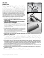
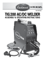
Part #12746
TIG 200 AC/DC WELDER
ASSEMBLY & OPERATING INstructions
TIG Welding is the most controllable, efficient and most versatile method of welding many metals including steel, stainless steel,
aluminum and more. Your Eastwood TIG200 Welder with High-Frequency Inverter Technology is capable of welding thin or heavy gauge
steel and aluminum with precision and ease. The Voltage self-sensing circuitry automatically detects a power source range of 110 to 240
Volts and delivers from 10 up to 200 Amps of AC or DC current at super-high frequency with the added advantage of a light weight unit.
The included foot pedal provides the operator with the precise Amperage control required when welding. A high frequency start feature
guarantees an instant arc strike with no tungsten contamination.
STATEMENT OF LIMITED WARRANTY
The Eastwood Company (hereinafter “Eastwood”) warrants to the end user (purchaser) of all new welding and cutting equipment (collectively called the “products”) that it will
be free of defects in workmanship and material. This warranty is void if the equipment has been subjected to improper installation, improper care or abnormal operations.
WARRANTY PERIOD:
All warranty periods begin on the date of purchase from Eastwood. Warranty Periods are listed below, along with the products covered during those warranty periods:
3 Year Warranty on Material, Workmanship, and Defects:
• Eastwood TIG 200 Welder
Items not covered under this warranty: Collets, collet bodies, tungsten, nozzles, and ground clamp and cable.
All other components are covered by the warranty and will be repaired or replaced at the discretion of Eastwood.
2 Years:
• All Welding Helmets.
CONDITIONS OF WARRANTY TO OBTAIN WARRANTY COVERAGE:
Purchaser must first contact Eastwood at 1-800-345-1178 for an RMA# before Eastwood will accept any welder returns.
Final determination of warranty on welding and cutting equipment will be made by Eastwood.
WARRANTY REPAIR:
If Eastwood confirms the existence of a defect covered under this warranty plan, Eastwood will determine whether repair or replacement is the most suitable option
to rectify the defect. At Eastwood’s request, the purchaser must return, to Eastwood, any products claimed defective under Eastwood’s warranty.
FREIGHT COSTS:
The purchaser is responsible for shipment to and from Eastwood.
WARRANTY LIMITATIONS:
EASTWOOD WILL NOT ACCEPT RESPONSIBILITY OR LIABILITY FOR REPAIRS UNLESS MADE BY EASTWOOD. EASTWOOD’S LIABILITY UNDER THIS WARRANTY SHALL NOT
EXCEED THE COST OF CORRECTING THE DEFECT OF THE EASTWOOD PRODUCT. EASTWOOD WILL NOT BE LIABLE FOR INCIDENTAL OR CONSEQUENTIAL DAMAGES (SUCH
AS LOSS OF BUSINESS, ETC.) CAUSED BY THE DEFECT OR THE TIME INVOLVED TO CORRECT THE DEFECT. THIS WRITTEN WARRANTY IS THE ONLY EXPRESS WARRANTY
PROVIDED BY EASTWOOD WITH RESPECT TO ITS PRODUCTS. WARRANTIES IMPLIED BY LAW SUCH AS THE WARRANTY OF MERCHANTABILITY ARE LIMITED TO THE
DURATION OF THIS LIMITED WARRANTY FOR THE EQUIPMENT INVOLVED. THIS WARRANTY GIVES THE PURCHASER SPECIFIC LEGAL RIGHTS.
THE PURCHASER MAY ALSO HAVE OTHER RIGHTS WHICH VARY FROM STATE TO STATE.
SPECIFICATIONS
Output
Amperage
Range
Maximum
Output No Load
Voltage
10-200 A
AC/DC
51 V DC
Input
Voltage
120 VAC
50-60 Hz
220 VAC
50-60 Hz
Rated
Duty
Cycle
Pre
Gas
Flow
Post
Gas
Flow
Weight
45%
@ 150 A
0.1-1.0 Sec
2-8 Sec
45 Lbs.
Overall
Dimensions
19.1”
(486 mm) x
9.8”
(248 mm) x
20.0”
(508 mm)
DUTY CYCLE
The Rated Duty Cycle refers to the amount of welding that can be done within an amount of time. The Eastwood TIG200 has a duty
cycle of 45% at 150 Amps. It is easiest to look at your welding time in blocks of 10 Minutes and the Duty Cycle being a percentage
of that 10 Minutes. If welding at 150 Amps with a 45% Duty Cycle, within a 10 Minute block of time you can weld for 4.5 Minutes
with 5.5 Minutes of cooling for the welder. To increase the Duty Cycle you can turn down the Amperage Output control. Going above
150 Amps will yield a lower duty cycle.
2
Eastwood Technical Assistance: 800.544.5118 >> [email protected]
Safety Information
Flammability Hazard
• Before beginning, make sure the work surface is cleaned of any oils, coatings or other materials which can ignite and or emit
dangerous fumes or vapors.
• Molten metal can be ejected away from the welding area with significant force and speed. Make sure the entire work area is clear
from flammable or easily damaged materials or objects.
High Voltage Danger
The unit contains no user serviceable parts! Contact with the torch when the button is depressed will result in a serious shock and
severe burns! This device also produces High-Frequency, Radio-Frequency Emissions which can damage sensitive electronic equipment
in the area. Keep all cell-phones, cameras, watches and other electronic equipment at least 6’ away from the Power Unit and Torch.
Important Note: If you have a medical condition or pacemaker check with your doctor before using as the RF emissions may
cause interference.
Electrical Safety Do’s
• Make sure you, your work area, and your equipment are dry. Avoid welding in high humidity and with excessive perspiration.
• If you are using an extension cord (not recommended due to excessive Voltage drop), make sure it is a grounded cord in sound
condition with no damage or frays, and of the correct wire gauge. (220 Volt @ 10 gauge minimum / 110 Volts @ 12 gauge minimum).
• Keep all cords as far away from the welder unit as possible to avoid any possibility of arcing to the internal transformer.
This includes the power cord, torch feed cord and ground clamp cord.
• Remove change, watches or other metallic objects from your clothing.
• Sweep up all metal grinding particles and dirt from the floor before beginning welding.
• Use a non-metallic chair.
• To further isolate yourself from ground, position yourself over a rubber mat while welding.
• Ensure that proper sized circuit breakers and wiring are in place prior to use: 20 Amp for 110 Volt operation and
30 Amp for 240 Volt operation. Single Phase Only.
Electrical Safety Don’ts
•
•
•
•
•
Never bypass the ground plug. Grounding is necessary for proper operation of the unit and reduces shock hazard.
Do not touch the torch tip until after the activation switch is off and the unit is UNPLUGGED.
Do not use the unit if any component should become damaged or show signs of excessive wear.
Never handle the torch and the feed cable, power cord or welder cabinet at the same time. Fatal shock can occur.
Avoid welding in extreme humidity or while heavily perspired.
To order parts and supplies: 800.345.1178 >> eastwood.com
3
Required Items
Before you begin using the Eastwood TIG Welding System, make sure you have the following:
• Our TIG200 is supplied with the popular NEMA 50P plug, requiring a NEMA 50 receptacle. If a 220-240 VAC, 30 Amp outlet
is used a UL listed 30 Amp plug may be installed by a licensed and qualified electrician.
• The TIG200 will also operate on a 110-120 VAC 20 Amp circuit. To operate on this voltage it is necessary to connect the included
adaptor cord to the plug hard wired to the TIG200.
• A clean, safe, well-lit, dry and well-ventilated work area.
• A non-flammable, long sleeve shirt or jacket (Eastwood #12762L, XL, XXL).
• Heavy Duty Welding Gloves (#12590)
• An Auto Darkening Welding Mask (Eastwood #13203 or equivalent) to provide eye protection during welding operations.
NOTE: MUST be a #11 lens or darker.
• A compressed gas cylinder containing 100% Argon (must be used when TIG welding and is available at any welding supply facility).
• Dedicated stainless steel wire welding brushes for each material to be welded.
• A dedicated fine grit synthetic stone grinding wheel or a Tungsten Sharpener.
Power Requirements
The Eastwood TIG200 AC/DC is Voltage sensing; it will automatically operate on 110-120 VAC, 50/60 Hz., or 220-240 VAC, 50/60
Hz. Eastwood recommends at a minimum a properly grounded 110-120 VAC 50/60Hz., 20 Amp circuit or 220-240 VAC 50/60Hz.,
30 Amp circuit.
before you begin
Remove all items from the box. Compare with list below to make sure unit is complete.
• TIG200 AC/DC Welder with NEMA50-P Plug
• Shielding Gas Regulator
• Shielding Gas Hose
• Ground Cable with Clamp (10’)
• TIG Torch (17 Series) which accepts industry standard cups, collets and collet bodies (14’)
• Foot Pedal for Amperage Control
• 110-120 VAC to 220-240 VAC Adaptor Plug
• Instruction Manual
• Hand Held Shield
• Hammer/Brush
• #7 Gas Nozzle (7/16”)
• #6 Gas Nozzle (3/8”)
• #5 Gas Nozzle (5/16”)
• Long Back Cap
• Short Back Cap
• 3/32” Collet Body
• 3/32” Collet
• 1/16” Collet
• 2.0mm Collet
• 2.0mm Red (Thoriated Tungsten)
4
Eastwood Technical Assistance: 800.544.5118 >> [email protected]
COMPONENTS AND CONTROLS
1. Power Switch – The Power Switch also serves as the overload Circuit Breaker
and is located at the right of the rear panel (Fig. C).
2. Amperage (Front Panel) – Set the Output Amperage Knob marked “A” (Fig. A)
located at upper left of the top panel to an appropriate setting based on the thickness
and type of the metal being welded. (Refer to Data Chart for actual settings).
3. Amperage (Foot Pedal) – Same operation as the panel control but is used while
the foot pedal is in use (Fig B).
4. Clearance Effect – The Clearance Effect Knob (Fig. A) is located at the
upper right of the top panel. Clearance Effect will control how much cleaning
versus penetration occurs. The more negative the value will result in greater
penetration and less cleaning and the more positive the value will result in less
penetration but greater cleaning.
5. Pre Flow – The Pre Flow Knob located at the lower left of the top panel (Fig. A)
controls the time (in seconds) that the shielding gas starts to flow after the trigger or
foot pedal is press before the arc starts. (Refer to Data Chart for actual settings).
6. Post Flow – The Post Flow Knob located at the lower right of the top panel (Fig. A)
controls the time (in seconds) that the shielding gas continues to flow after the
trigger or foot pedal is released. (Refer to Data Chart for actual settings).
7. Gas Flow – The included regulator limits the shielding gas flow from the bottle
and also displays how much gas is left in the bottle. The Gas Flow Indicator
Gauge is located on the left side and is generally set between 12 to 21 SCFH.
(Refer to Data Chart for actual settings). This is explained in further detail in
the Preparing to Weld section of this manual. The gauge on the right indicates the
pressure left in the tank.
8. AC/DC – The DC setting is used for welding steel and stainless steel while the
AC setting is used for welding aluminum. (Fig. A) (Refer to Data Chart for
actual settings).
9. Foot Pedal/Panel Control – The Foot Pedal/Panel Control selection switch
is located at the upper right of the top panel and when set in the ‘Foot Pedal’
position, the Foot Pedal control is activated. When set to the ‘Panel Control’
position, the Torch Trigger is activated. (Fig. A)
10.Torch Switch – The switch on the torch (Fig. D) controls starting and stopping
the arc. When using the torch switch the Amperage is set on the adjustment knob
on the front panel of the welder.
11.Foot Pedal – The foot pedal is for starting and stopping the arc as well as controlling
the Amperage during the weld. When using the foot pedal the Amperage is set by
the adjustment knob on the side of the foot pedal. (Fig. B)
FIG. A
FIG. B
FIG. C
FIG. D
DATA CHART (Also located on TOP of welder)
To order parts and supplies: 800.345.1178 >> eastwood.com
5
sETUP
FIG. E
SHIELDING GAS CONNECTION
A Shielding Gas Bottle is not included with your Eastwood TIG200 but is necessary
while TIG welding. A Shielding Gas Bottle can be bought at most local Welding
Supply Stores. Eastwood recommends the use of 100% Argon shielding gas
when TIG welding Steel, Aluminum, and Stainless Steel.
1. Place the Eastwood TIG200 in its dedicated area or on a welding cart.
2. Secure your Shielding Gas Bottle to a stationary object or mount to your
welding cart if it is equipped to hold one so that the cylinder cannot fall over.
3. Remove the cap from the Shielding Gas Bottle.
4. Insert the large brass male fitting on the Shielding Gas Regulator into
the female fitting on the Shielding Gas Bottle. (Fig. E) NOTE: Do not use
White Teflon Tape on this connection as it is a tapered thread and does not
require it, if you have a leak check for burrs or dirt in the threads. If the leak
persists, use gas type sealing tape.
5. Tighten the fitting with a wrench till snug, do not over tighten.
6. Connect either end of the Gas Line included with your Eastwood TIG200 to
the fitting on the regulator and tighten with a wrench until snug.
7. Connect the other end of the gas line to the fitting on the rear of the
Eastwood TIG200 and tighten with a wrench until snug. (Fig. F)
FIG. F
FIG. G
Torch Connection
1. If you are going to be using the switch on the torch to start the welding arc,
omit this step.
2. Connect the Black 4 pin plug on the Foot Pedal to the Switch Connection as
shown in FIG G.
3. Connect the Metal 2 Pin Plug on the Foot Pedal to the Foot Pedal Connection
as shown in FIG G.
6
Eastwood Technical Assistance: 800.544.5118 >> [email protected]
Foot Pedal
Torch
Switch/Foot
Pedal
✓
Foot Pedal Connection
✓
1. Locate the Ground Cable and Clamp.
2. The Ground Cable connection is located at the far right of the front panel as
shown in FIG G. With the Key on the connector in the 12 O’clock position,
insert the connector and turn 180° clockwise to lock in the connector.
Gas Flow
Through Power Cable
✓
Ground Cable Connection
✓
1. Install the plastic connection cover onto the brass torch fitting on the
torch cable.
2. Connect the female brass fitting on the torch cable to the male brass fitting
on the welder. (Fig. G)
3. Use a wrench and tighten until snug. DO NOT OVERTIGHTEN.
4. Connect the black 4 pin plug to the Torch Switch Connection as shown in FIG G.
(NOTE: Omit this step if you will be using the foot pedal for Amperage control)
Ground
Cable
PREPARING TO WELD
Tungsten
FIG. H
Torch Disassembly/Assembly
DISASSEMBLY:
Collet
Gas Nozzle
Back Cap
✑✒✓✔
✑✒✓✔
Collet Body
✑✒✓✔
ASSEMBLY:
✑✒✓✔
1. Make sure the welder is turned off and unplugged.
2. Remove the back cap from the torch.
3. If there is a tungsten installed in the torch pull
it out of the front of the torch
4. Slide the collet out of the torch.
5. Unscrew and remove the gas nozzle.
6. Unscrew and remove the collet body.
1. Select a collet body that matches your tungsten diameter size and thread it back into the front of the torch.
2. Select a collet that matches your tungsten diameter size. Insert the tungsten into the collet and put the collet and tungsten back
into the torch.
3. The cup size should be changed according to shielding gas requirements for the material being welded. This size can be referenced
on the suggested settings chart. Select the correct gas nozzle and thread it onto the collet body.
4. Reinstall the back cap to lock the tungsten in place. Always make sure the tungsten protrudes 1/8” to 1/4” beyond the gas nozzle.
SHARPENING THE TUNGSTEN
To avoid contamination of the Tungsten and ultimately the weld, it is imperative to have a dedicated grinding wheel used for Tungsten
grinding only. A fine grit standard 6” synthetic stone grinding wheel on a bench top grinder is sufficient
or specifically designed Tungsten Grinders are available.
1. Shut off the welder.
FIG. I
2. Make sure the Tungsten and Torch are sufficiently cooled for handling then
loosen and remove the Back Cap then the Collet (Fig H) and remove the
Tungsten from the FRONT of the Torch only. (Removing from the rear will
damage the Collet).
3. If the tungsten is used and the end is contaminated, use pliers or a suitable
tool to grip the tungsten above the contaminated section and snap off the end
of the Tungsten.
4. Holding the Tungsten tangent to the surface of the grinding wheel, rotate the
tungsten while exerting light pressure until a suitable point is formed (Fig I).
5. The ideal tip will have the length of the conical portion of the sharpened area at
2-1/2 times the Tungsten rod diameter (Fig J).
6. Replace the Tungsten in the Collet with the tip extending 1/8”-1/4”
beyond the Gas Nozzle, then re-tighten the Back Cap.
To order parts and supplies: 800.345.1178 >> eastwood.com
FIG. J
7
SETTINGS SELECTION
With the materials selected of which you will be welding you can begin to set up the welder for the specific material.
1. AC/DC – The type of current will need to be selected depending on the type of material being welded. For the most part
when welding steels the switch will be set to DC and when welding aluminum the switch will be set to AC.
2. Clearance Effect – This step can be omitted if welding in DC. If welding in AC this will need to be set. The more negative
the value will result in greater penetration and less cleaning and the more positive the value will result in less penetration
but greater cleaning. For suggested settings refer to the data chart on the welder.
3. Foot Pedal/Panel Control – Determine whether you will be using the switch on the torch or the foot pedal for arc starting
and stopping and put the selector switch in the appropriate position. Note that some connections changes will be necessary
also when switching the control type. These connection changes are covered in the Set-Up section of this manual.
4. Amperage – If welding using the switch on the torch to control the arc, Set the Output Amperage Knob marked “A” (Fig. A)
located at upper left of the top panel to an appropriate setting based on the thickness and type of the metal being welded.
(Refer to Data Chart for actual settings). If welding using the foot pedal to control the arc, it uses the same operation as the
panel control but is adjusted on the side of the foot pedal rather than the front panel. (Fig. A)
5. Pre Flow – This adjustment controls the time (in seconds) that the shielding gas starts to flow before the arc starts.
(Refer to Data Chart for actual settings).
6. Post Flow – This adjustment controls the time (in seconds) that the shielding gas flows after the arc stops.
(Refer to Data Chart for actual settings).
7. Power Switch – Once all of the settings have been selected and the torch assembled and ready to use, the welder can be
plugged in and turned on.
8. Shielding Gas Flow – Set the Gas Flow Rate to the appropriate value with the Knob located at the left side of the regulator.
Shielding Gas Flow Adjustment
After connecting your Shielding Gas Regulator, the gas flow rate needs to be adjusted so that the proper amount of Shielding Gas
is flowing over your weld. If there is too little gas flow there will be porosity in your welds as well as excessive spatter, if there is
too much gas flow you will be wasting gas and may affect the weld quality. The included regulator has 2 gauges on it; the gauge
on the left is your flow rate while the gauge on your right is your tank pressure.
1.
2.
3.
4.
Open your Shielding Gas tank valve all the way.
Adjust the knob on the regulator to ~20 CFH.
Turn on the welder and trigger the torch switch or foot pedal which will start the gas flow.
As you trigger the torch switch or foot pedal, you will notice that as the gas flow starts the needle on the gauge drops to a
steady reading. The reading while flowing is the value you want to read.
5. The gas flow should be set to 12-21 CFH while flowing depending on the material and thickness being welded. The CFH
(Cubic Feet per Hour) scale is the inside scale in red on your flow gauge. 20 CFH is the most typical flow rate but it may
need to be adjusted in some cases depending if there is a slight breeze or some other instance where additional
shielding gas is required to prevent porosity in the weld.
6. When finished welding remember to close the gas valve on the bottle.
8
Eastwood Technical Assistance: 800.544.5118 >> [email protected]
WELDING
FIG. J
IMPORTANT NOTE:
These instructions are intended only to provide the user with some familiarity
of the Eastwood TIG200. TIG welding is a highly complex procedure with many
variables. If you have no experience with TIG welding; it is extremely important
to seek the advice of someone experienced in TIG welding for instruction, enroll
in a local technical school welding course or study a comprehensive how-to DVD
and obtain a good quality reference book on TIG welding as there is a moderate
learning curve necessary before achieving proficiency in TIG Welding. Before
attempting to use this unit on an actual project or object of value, practice on
a similar material as there are many variables present and settings required
when TIG welding different metals such as steel or aluminum. It is also strongly
recommended that the user adhere to the American Welding Society guidelines,
codes and applications prior to producing welds where safety is affected.
90°
75°
FIG. K
1. Turn the Power Switch/Circuit Breaker to the on position.
2. Slowly open the gas cylinder valve. NOTE: Always open valve fully to avoid
shielding gas leakage.
3. Depress gun trigger switch or foot pedal and adjust the flow regulator.
(Refer to Data Chart for actual settings).
FIG. L
4. Grounding is very important, place the Ground Cable Clamp on a clean, bare
area of your work piece as close to the welding area as possible to minimize
the chance of shock. Scrape, wire brush, file or grind a bare area to achieve
a good ground to assure safety.
5. Use a dedicated stainless steel brush or flap-disc to clean the areas to be
welded. This is particularly critical on aluminum as a microscopic layer of
oxidation can prevent an arc and actually produce a poor-quality,
contaminated weld. Do not use the brush or flap-disc for any other purpose
and keep one for steel and one for aluminum.
6. Make sure all your safety gear is in place (Welding Mask, Welding Gloves, Non-Flammable Long Sleeve Apparel) and the area is
completely free of flammable material.
7. Although it is a matter of developing a personal style, a good starting point for best results is achieved by holding the tip at a 75°
angle. Hold the Filler Metal Rod at a 90° angle to the Tungsten Tip (Fig. J). Never allow the Tungsten Tip to touch the welding surface
or material rod. Doing so will quickly destroy the tip and contaminate the weld. If this happens, remove the Tungsten and regrind
the tip. It is best to hold the tungsten 1/8” from the surface.
8. With your Welding Shield and all safety gear in place, depress the foot pedal or trigger and practice “Forming A Puddle” with the
Tungsten Tip. Once you become familiar with this step. Practice the “Dip and Pull” technique with the Filler Metal Rod and Torch.
“Dip and Pull” is the practice of forming a puddle, moving the torch while maintaining the puddle and adding filler rod metal to the
puddle by “dipping and pulling” as you go; being careful not to allow the tungsten to contact the puddle or rod.
9. Keep in mind that you MUST let the shielding gas flow over the weld after releasing the trigger or pedal. Failure to do so will allow
the welded area to oxidize compromising the weld integrity.
10.Constantly be aware that TIG welding quickly generates heat in the work piece and torch. Severe burns can quickly occur by
contacting hot metal pieces.
11.When done, shut off the Power Switch and close the Shielding Gas Tank valve completely.
To order parts and supplies: 800.345.1178 >> eastwood.com
9
Problem
Problem
TROUBLESHOOTING
Problem
Arc is triggered but will not start
Cause
Incomplete CauseCircuit
Incomplete CauseCircuit
Incorrect Tungsten
Arc is triggered but will not start
Incomplete Circuit
Incorrect Tungsten
No shielding gas
Arc is triggered but will not start
Incorrect ungsten
Wrong PTolarity
No shielding gas
Wrong Polarity
No shielding gas
Wrong Polarity
Poorly prepped tungsten
Poor Gas Flow
Poorly prepped tungsten
Arc wanders and it is hard to concentrate heat in a specific area
Arc wanders and it is hard to concentrate heat in a specific area
Arc wanders and it is hard to concentrate heat in a specific area
Contaminated ungsten
Poor Gas FTlow
Poorly prepped tungsten
Incorrect arc Tlungsten
ength
Contaminated Poor Gas Flow
Incorrect arc cTlircuit
ength
Contaminated ungsten
Incomplete Incorrect arc clircuit
ength
Incomplete Contaminated base metal
Incomplete circuit
Contaminated base metal
Incorrect Clearance Effect (AC)
Contaminated base metal
Incorrect Clearance Effect (AC)
Incorrect Clearance Effect (AC)
Poor Gas Flow
Contaminated Poor Gas fFiller lowmetal
Porosity in weld bead
Contaminated base m
metal
Contaminated Poor Gas fFiller low etal
Porosity in weld bead
Contaminated b
ase m
metal
etal
Contaminated filler Poor Shielding
Porosity in weld bead
Contaminated base metal
Poor Shielding
Incorrect Tungsten Stick Out
Poor Shielding
Incorrect Tungsten Stick Out
Incorrect Tungsten Stick Out
Contaminated Tungsten
Contamination in weld bead
Contaminated Metal
Contaminated FTiller ungsten
Contamination in weld bead
Contaminated Metal
Contaminated FTiller ungsten
Contaminated Base Metal
Contamination in weld bead
Contaminated Filler Metal
Contaminated Base Metal
Contaminated Base Metal
Make sure polarity is set for the correct material. AC should Follow guidelines for prepping tungsten. be used for aluminum while DC should be used for steel.
Adjust the flow rate of the shielding gas (refer to settings chart). C
heck for loose fittings w
here gas could be leaking.
Follow guidelines for prepping tungsten. Remove t
ungsten f
rom t
orch a
nd break ff contaminated Adjust the flow rate of the shielding gas o(refer to settings section a
nd r
esharpen.
chart). C
heck for loose fittings w
here gas could be leaking.
Follow guidelines for prepping tungsten. Make sure the tungsten is held 1/8 to 1/4 inch off the work Remove tungsten from orch and break ff contaminated Adjust the flow rate of tthe shielding gas o(refer to settings piece.
section a
nd r
esharpen.
chart). Check for loose fittings where gas could be leaking.
Check round ake sure that the goround is ork on a Make sGure the ctonnection. ungsten is hM
eld 1/8 to 1
/4 inch ff the w
Remove tungsten from torch and break off contaminated freshly cleaned surface and close to the welding area. It is piece.
section and resharpen.
suggested to wceld towards the ground connection.
Check round ake sure that the goround is ork on a Make sGure the tonnection. ungsten is hM
eld 1/8 to 1
/4 inch ff the w
Clean b
ase m
etal m
aking s
ure t
o r
emove aelding ny oil, adrea. ebris, freshly c
leaned s
urface a
nd c
lose t
o t
he w
I
t i
s piece.
coatings, otr o mwoisture. If base mgetal is aluminum make sure all suggested eld t
owards t
he round c
onnection.
Check Ground connection. Make sure that the ground is on a of the boase xide mis removed using etither a dedicated Clean etal making sure o rtemove ny oil, asdtainless ebris, freshly cleaned surface and close o the waelding rea. It is brush o
r f
lap w
heel.
coatings, otr o mwoisture. If base mgetal is aluminum make sure all suggested eld towards the round connection.
Shift moore negative on tu
he Clearance aE dffect knob so less heat of the xide removed sing edicated Clean base mis etal making sure etither o remove any oil, sdtainless ebris, is going into tw
he tungsten.
brush o
r f
lap heel.
coatings, or moisture. If base metal is aluminum make sure all Shift moore negative on tu
he Clearance knob sstainless o less heat of the xide is removed sing either aE dffect edicated is g
oing i
nto t
he t
ungsten.
brush or flap wheel.
Shift more negative on the Clearance Effect knob so less heat Adjust the flow rate of the shielding gas (refer to settings is going into the tungsten.
chart). Check for loose fittings where gas could be leaking.
Clean etal making sure to remove any otil, ebris, or Adjust filler the fm
low rate of the shielding gas (refer o dsettings moisture. chart). Check for loose fittings where gas could be leaking.
Clean ase metal etal m
making aking ssure ure tto o rremove emove aany ny oil, ddebris, ebris, Clean b
filler Adjust the fm
low rate of the shielding gas (refer otil, o settings or coatings, or moisture. moisture. chart). Check for loose fittings where gas could be leaking.
Make sure o etal be in n area with wind aand ith daebris, ny fans Clean ase tm
m
maaking aking ure o nrro emove ny w
il, Clean b
filler etal m
ssure tto emove any ooil, debris, or turned off. W
ind or fans will blow the shielding gas away from coatings, o
r m
oisture. moisture. the weld causing orosity.
Make sure o etal be ip
n n area with wind aand ith daebris, ny fans Clean b
ase tm
maaking sure to nro emove ny w
oil, Adjust tohe tW
ungsten sans o that 1b/8 to t1he /4in is sticking oaut of tfhe turned ff. ind o
r f
w
ill low s
hielding g
as way rom coatings, or moisture. collet.
the w
eld c
ausing p
orosity.
Make sure to be in an area with no wind and with any fans Adjust ungsten o that to t1he /4in is sticking of tfhe turned tohe ff. tW
ind or fsans will 1b/8 low shielding gas oaut way rom collet.
the weld causing porosity.
Adjust the tungsten so that 1/8 to 1/4in is sticking out of the Remove tungsten from torch and break off contaminated collet.
section and resharpen.
Clean filler metal m
aking sure atnd o rb
emove oil, debris, or Remove tungsten from torch reak oaff ny contaminated moisture. section and resharpen.
Clean b
ase m
metal etal m
making aking ssure ure tto o remove emove aany ny ooil, il, ddebris, ebris, or Clean filler Remove tungsten from torch and rb
reak off contaminated coatings, o
r m
oisture. I
f b
ase m
etal i
s a
luminum m
ake sure all moisture. section and resharpen.
of t
he o
xide i
s r
emoved u
sing e
ither a
d
edicated s
tainless Clean ase m
metal etal m
making aking ssure ure tto o rremove emove aany ny ooil, il, ddebris, ebris, or Clean b
filler brush or folap heel. If base metal is aluminum make sure all coatings, r mwoisture. moisture. of the boase xide mis removed using a dedicated Clean etal making sure etither o remove any oil, sdtainless ebris, brush or folap heel. If base metal is aluminum make sure all coatings, r mwoisture. of the oxide is removed using either a dedicated stainless Adjust the flow rate of the shielding gas (refer to settings brush or flap wheel.
chart). Check for loose fittings where gas could be leaking.
Shift mtore egative he sChielding learance Effect knob o less heat Adjust he fnlow rate oon f tthe gas (refer to ssettings Improper Clearance Effect (AC)
Poor Gas Flow
is going Ciheck nto the Melting Tungsten
chart). for tlungsten.
oose fittings where gas could be leaking.
Wrong Size Tungsten
Increase tungsten diameter. Refer to cEhart for proper sizing.
Shift mtore egative he sChielding learance ffect knob o less heat Adjust he fnlow rate oon f tthe gas (refer to ssettings Improper Cnough learance Effect (AC)
Poor G
as F
low
Not e
p
ost f
low
Increase p
ost f
low t
ime t
o a
llow t
he g
as t
o c
ool t
he t
ungsten.
is going Ciheck nto the Melting TEastwood
ungsten Technical Assistance: 800.544.5118 >> [email protected]
chart). for tlungsten.
oose fittings where gas could be leaking.
Incorrect Shielding Gas
Only use t1ungsten 00% Argon when TRIG Welding. Wrong Size Tungsten
Increase diameter. efer to cEhart proper sizing.
Shift more negative on the Clearance ffect for knob so less heat Improper Cnough learance Effect (AC)
Not e
p
ost f
low
Increase p
ost f
low t
ime t
o a
llow the gas to cool the tungsten.
is going into the tungsten.
Melting Tungsten
Incorrect Shielding Gas
Only use 100% Argon when TIG Welding. Poor Gas Flow
10
Fix
Check Ground connection. Make sure that the ground is on a freshly cleaned surface and close Fix to the welding area. It is suggested to wceld towards M
the ground connection.
Check Ground onnection. ake sure that the ground is on a Consult c
hart f
or p
roper t
ungsten f
or t
he ase maetal freshly cleaned surface and close rea. bIeing t is Fix to the wbelding welded. I
n m
ost c
ases P
ure T
ungsten w
ill b
e f
or a
luminum suggested to wceld towards M
the ground connection.
Check Ground onnection. ake sure that the ground is on a and Thoriated will be for tsungsten teel.
Consult hart for proper or the ase maetal freshly ccleaned surface and close tfo the wbelding rea. bIeing t is Make s
ure t
he s
hielding g
as cungsten ylinder is urned all atluminum he way welded. In tm
cases Pure tThe wtcill be for suggested o ost weld towards ground onnection.
open and set aw
t the correct flow rate.
and Thoriated be for tsungsten teel.
Consult chart for ill proper for the base metal being Make ssure p
olarity is set gfas or cthe correct material. Ahe C swhould Make ure t
he s
hielding ylinder is urned all atluminum ay welded. In most cases Pure Tungsten wtill be for be used for aluminum while flow DC srhould be used for steel.
open a
nd s
et a
t t
he c
orrect ate.
and Thoriated will be for steel.
Make olarity is set gfas or cthe correct material. C swhould Make ssure ure p
the shielding ylinder is turned all tAhe ay be u
sed f
or a
luminum w
hile D
C s
hould b
e u
sed f
or s
teel.
open and set at the correct flow rate.
TROUBLESHOOTING
To order parts and supplies: 800.345.1178 >> eastwood.com
11
ACCESSORIES
TIG WIRE & TUNGSTEN:
•
•
•
•
•
•
•
•
•
•
#12253 – ER70S-2 Steel TIG Wire 1/16-36”
#12254 – ER70S-2 Steel TIG Wire 3/32-36”
#12375 – 4043 Aluminum TIG Wire 1/16-36”
#12376 – 4043 Aluminum TIG Wire 3/32-36”
#12463 – 308L Stainless TIG Wire 1/16-36”
#12464 – 308L Stainless TIG Wire 3/32-36”
#12869 – Pure Tungsten (Green) 1/16-7” 2pc
#12870 – Pure Tungsten (Green) 3/32-7” 2pc
#12871 – Thoriated Tungsten (Red) 1/16-7” 2pc
#12872 – Thoriated Tungsten (Red) 3/32-7” 2pc
Replacement Items:
•
•
•
•
•
•
•
•
#13483 – TIG200 Collet Body (1.6mm; 1/16”)
#13484 – TIG200 Collet Body (2.4mm; 3/32”)
#12822 – TIG200 Collet (1.6mm; 1/16”)
#12824 – TIG200 Collet (2.4mm; 3/32”)
#12825 – TIG200 Long Back Cap
#12819 – TIG200 Gas Nozzle (9.8mm; 3/8”)
#12821 – TIG200 Gas Nozzle (11.2mm; 1/2”)
#13953 – TIG Accessory Kit
OTHER WELDING ACCESSORIES:
•
•
•
•
•
•
•
•
•
•
#11947 – Flap Disc 60 Grit 4.5” Diameter 7/8” Hole
#12590 – Welding Gloves Large
#12589 – Welding Gloves Medium
#12099 – Auto Darkening Welding Helmet
#19079S – Stainless Steel Brush
#51139 – Copper 3 x 3 Welders Helper Set
#50739 – Master Welder’s Helper Panel Holding Kit
#19015 – Welders Pliers
#12762L, XL, XXL – Welding Jacket
#11616 – TIG200 Welding Cart
If you have any questions about the use of this product, please contact
The Eastwood Technical Assistance Service Department: 800.544.5118 >> email: [email protected]
The Eastwood Company 263 Shoemaker Road, Pottstown, PA 19464, USA
US and Canada: 800.345.1178 Outside US: 610.718.8335
Fax: 610.323.6268 eastwood.com
© Copyright 2012 Easthill Group, Inc.
Instruction part #12746Q
Rev. 6/12