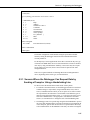
1
INSTRUCTION MANUAL
SDM-SIO4 4-Channel
Serial I/O Interface
Revision: 2/04
C o p y r i g h t ( c ) 1 9 9 6 - 2 0 0 4
C a m p b e l l S c i e n t i f i c , I n c .
Warranty and Assistance
The SDM-SIO4 4-CHANNEL SERIAL I/O INTERFACE is warranted by
CAMPBELL SCIENTIFIC, INC. to be free from defects in materials and
workmanship under normal use and service for twelve (12) months from date
of shipment unless specified otherwise. Batteries have no warranty.
CAMPBELL SCIENTIFIC, INC.'s obligation under this warranty is limited to
repairing or replacing (at CAMPBELL SCIENTIFIC, INC.'s option) defective
products. The customer shall assume all costs of removing, reinstalling, and
shipping defective products to CAMPBELL SCIENTIFIC, INC. CAMPBELL
SCIENTIFIC, INC. will return such products by surface carrier prepaid. This
warranty shall not apply to any CAMPBELL SCIENTIFIC, INC. products
which have been subjected to modification, misuse, neglect, accidents of
nature, or shipping damage. This warranty is in lieu of all other warranties,
expressed or implied, including warranties of merchantability or fitness for a
particular purpose. CAMPBELL SCIENTIFIC, INC. is not liable for special,
indirect, incidental, or consequential damages.
Products may not be returned without prior authorization. The following
contact information is for US and International customers residing in countries
served by Campbell Scientific, Inc. directly. Affiliate companies handle
repairs for customers within their territories. Please visit
www.campbellsci.com to determine which Campbell Scientific company
serves your country. To obtain a Returned Materials Authorization (RMA),
contact CAMPBELL SCIENTIFIC, INC., phone (435) 753-2342. After an
applications engineer determines the nature of the problem, an RMA number
will be issued. Please write this number clearly on the outside of the shipping
container. CAMPBELL SCIENTIFIC's shipping address is:
CAMPBELL SCIENTIFIC, INC.
RMA#_____
815 West 1800 North
Logan, Utah 84321-1784
CAMPBELL SCIENTIFIC, INC. does not accept collect calls.
SDM-SIO4 Table of Contents
PDF viewers note: These page numbers refer to the printed version of this document. Use
the Adobe Acrobat® bookmarks tab for links to specific sections.
1. Introduction....................................................................
1.1 What is the SDM-SIO4? ....................................................................... 1-1
1.2 Specifications........................................................................................ 1-3
1.2.1 Serial Ports .................................................................................. 1-3
1.2.2 SDM Port .................................................................................... 1-4
1.2.3 Case............................................................................................. 1-4
1.2.4 Power Requirements ................................................................... 1-4
1.2.5 Environmental Operating Range................................................. 1-5
1.2.6 Other Key Features ..................................................................... 1-5
1.3 'Talk-Through' Mode ............................................................................ 1-5
2. Installation and Hardware Set-Up ...........................2-1
2.1 Setting the SDM Address ..................................................................... 2-1
2.2 Selecting RS232 or 5V Logic for Each Port ......................................... 2-2
2.3 Connections to the SDM-SIO4 ............................................................. 2-2
2.3.1 Transient Protection and Grounding ........................................... 2-2
2.4 Power-on Tests — the Status LED ....................................................... 2-3
3. Understanding How the SDM-SIO4 Handles Data .3-1
3.1 Introduction........................................................................................... 3-1
3.1.1 Method of Entering Special / Control Characters ....................... 3-1
3.2 Input Filters........................................................................................... 3-2
3.2.1 Filter Types ................................................................................. 3-2
3.3 Output Formatting................................................................................. 3-6
3.3.1 Simple Output Formatter............................................................. 3-6
3.3.2 Output Format Strings................................................................. 3-7
4. Programming the SDM-SIO4....................................4-1
4.1
4.2
4.3
4.4
Command Line Operation and Structure .............................................. 4-1
Entering Commands ............................................................................. 4-1
Basic Commands .................................................................................. 4-2
Advanced Commands ........................................................................... 4-3
5. Programming the Datalogger ..................................5-1
5.1 Instruction 113 Parameters ................................................................... 5-1
5.1.1 Parameter 1 — Reps ................................................................... 5-1
5.1.2 Parameter 2 — Address .............................................................. 5-1
5.1.3 Parameter 3 — Mode .................................................................. 5-1
5.1.4 Parameters 4, 5 and 6 — SDM-SIO4 Command ........................ 5-2
5.1.5 Parameter 7 — Values per Rep ................................................... 5-2
5.1.6 Parameter 8 — Starting Input Location ...................................... 5-2
5.1.7 Parameters 9 and 10 — Multiplier and Offset ............................ 5-2
i
SDM-SIO4 Table of Contents
5.2 Commands and Options (Parameters 4, 5 and 6) .................................. 5-2
5.2.1 Understanding Parameter Options and Returned Values ............ 5-3
5.2.2 Command 1: Poll of Available Data........................................... 5-3
5.2.3 Command 2: Signatures ............................................................. 5-4
5.2.4 Command 3: Flush all Receive Buffers...................................... 5-4
5.2.5 Command 4: Send Data to Datalogger ....................................... 5-4
5.2.6 Command 5: Status .................................................................... 5-4
5.2.7 Command 6: Flush Transmit Buffer........................................... 5-5
5.2.8 Command 7: Activate Command Line ....................................... 5-5
5.2.9 Command 8: Poll Tx Buffers for Data ....................................... 5-5
5.2.10 Command 9: Flush Converted Data Buffer .............................. 5-6
5.2.11 Command 66: Send Single-Byte Data to Datalogger ................ 5-6
5.2.12 Command 67: Get Return Code ............................................... 5-6
5.2.13 Command 320: Send Data to SDM-SIO4 ................................. 5-6
5.2.14 Command 321: Execute Command Line Command ................ 5-6
5.2.15 Command 1024: Send String to Device ................................... 5-9
5.2.16 Command 1025: Transmit a Byte............................................. 5-9
5.2.17 Command 1026: Serial Port Status........................................... 5-9
5.2.18 Command 1027: ‘Manual’ Handshake Mode......................... 5-11
5.2.19 Command 2049: Set Communications Parameters ................. 5-11
5.2.20 Command 2054: Set Up Receive Filter .................................. 5-13
5.2.21 Command 2304: Transmit String and/or Data to Device ....... 5-13
5.2.22 Command 2305: Transmit Byte(s) ......................................... 5-15
5.3 SDM-SIO4 Configuration Examples ................................................. 5-15
5.3.1 Sensors Where the Datalogger Can Request Data by Sending a
Prompt or Using a Handshaking Line: ................................................ 5-17
5.3.2 Sensors Which Send Data Out Without Prompting................... 5-20
5.4 Outputting Datalogger Data ................................................................ 5-27
5.5 Flushing the Input and Output Buffers................................................ 5-29
5.6 Return Error Codes ............................................................................. 5-29
6. Data Error Detection ................................................ 6-1
6.1 Error detection with the SDM-SIO4 ..................................................... 6-1
6.2 Received Data ....................................................................................... 6-1
6.2.1 Example of Using Received Data Filters..................................... 6-3
6.2.2 CR10X Program Example........................................................... 6-4
6.3 Transmitted Data................................................................................... 6-7
6.3.1 Example of Using Transmitted Data Filters ................................ 6-8
6.3.2 CR10X Program Example........................................................... 6-8
6.3.3 Alternative CR10X Program ....................................................... 6-9
Appendices
Appendix A. ASCII Table .............................................A-1
Appendix B. Serial Port Data Transfer Modes...........B-1
B.1
B.2
B.3
B.4
B.5
Baud Rates........................................................................................... B-1
Stop Bits .............................................................................................. B-1
Data Length ......................................................................................... B-1
Parity Bits ............................................................................................ B-2
Serial Handshake Modes ..................................................................... B-2
ii
SDM-SIO4 Table of Contents
Appendix C. Limitations of the Talk-Through Mode. C-1
C.1 Limitations ...........................................................................................C-1
Figures
1-1. Schematic Diagram of the SDM-SIO4 ................................................ 1-2
Tables
1-1.
2-1.
2-2.
3-1.
SDM-SIO4 Serial Port Pin Configuration ........................................... 1-3
Address Settings .................................................................................. 2-1
Status LED Error Codes ...................................................................... 2-3
Fixed Strings Currently Allocated ....................................................... 3-8
iii
SDM-SIO4 Table of Contents
This is a blank page.
iv
Section 1. Introduction
The SDM-SIO4 has four configurable serial RS232 ports which allow it to be connected to
intelligent serial sensors, display boards, printers or satellite links. It can also be used in
many other applications where the data is transferred in a serial fashion. This device is
designed to send data to and receive data from the sensors, and process it in parallel with
the datalogger’s own program sequence, thus making the complete datalogging system
faster and more efficient.
The SDM-SIO4 can handle the incoming and outgoing data in many different ways. It can
either send data in the same format as sent from the datalogger or it can be programmed
to send pre-stored data strings to the sensor. Combinations of data sent from the
datalogger and pre-stored strings can be sent, allowing complex formatted data to be sent.
For input, the SDM-SIO4 can transfer data in the same form as received from a sensor to
the datalogger, or it can be programmed to filter out critical data from a sensor and only
pass back the data the datalogger requires.
NOTE
This manual assumes that you have a basic knowledge of the
terminology and theory of serial communications. For further
information please refer to one of the standard textbooks on this
subject.
1.1 What is the SDM-SIO4?
The SDM-SIO4 is a device that is connected to a datalogger through the
datalogger SDM port. The SDM port is specific to Campbell Scientific
dataloggers and acts as a high-speed data exchange mechanism. On some
dataloggers it is a dedicated port; on others it is implemented using control
ports C1, C2 and C3.
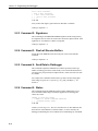
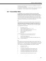
Figure 1-1, on the next page, is a Schematic Diagram giving an overview of the
functions of the SDM-SIO4. When used in conjunction with the following
sections of this manual, it may help you to understand how the SDM-SIO4
operates.
The datalogger program controls the sequence and timing of data exchange
with the sensors. However, unlike most other Campbell Scientific interfaces the
SDM-SIO4 can be configured in two ways:
1.
By inserting commands in the datalogger program
2.
By connecting a computer running a terminal emulation program to serial
port 1 on the SDM-SIO4. Pressing a switch on the SDM-SIO4 temporarily
switches this port to allow you to access a ‘command line’ (for entering
command strings in much the same way as entering commands at the DOS
prompt on a PC).
The ‘command line’ option allows you to store complex output strings and data
filters in the SDM-SIO4. This set-up information is stored in battery-backed,
1-1
Section 1. Introduction
write-protected memory, which allows you to set up the SDM-SIO4 in the
office and then move it to the site of installation in an unpowered state.
Command Line
Switch
Status
LED
PORT
Handshake Line
½
Handshake
Control
¾
¾
¿ Tx
Tx Buffer
Rx
Rx Buffer
À
¿
0
1
0
¿
¿
À
¿
¾
¿
¿
À
Filter Driver
Datalogger can
Execute Command
Line Commands
À
Format
Driver
& User
Strings
To Other Ports
½
Command Line
Control
CRC/SIG
Driver
À
¿
À
½
CRC/SIG
Driver
1
Switches Go to 1 if command
line active
Converted
Data Buffer
K K K
To Other Ports
¿
À
¾
Datalogger
Command
Control
¾
½
Control Lines
¿
À
¿
¿
Data
C1
HS
C2
SDE
C3
Data Lines
FIGURE 1-1. Schematic Diagram of the SDM-SIO4
1-2
to SDM port
of datalogger
Section 1. Introduction
1.2 Specifications
1.2.1 Serial Ports
The SDM-SIO4 has four serial ports which can be configured independently to
use different serial data formats and baud rates (from 25 to 115,200 baud).
These ports are 0-5V logic or ±5V for RS232 and are configured similar to a
PC ‘AT’ style DTE serial port.
Handshaking, to control the flow of data to and from a sensor, can be done by
the datalogger or SDM-SIO4 if needed, and can be in the form of hardware or
software protocols.
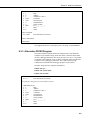
TABLE 1-1. SDM-SIO4 Serial Port Pin Configuration
NOTE
Pin No.
SDM-SIO4 Port
1.
RI ring indicate/DCD in
2.
RX in
3.
TX out
4.
DTR data terminal ready out
5.
Ground
6.
DSR in
7.
RTS request to send out
8.
CTS clear to send in
9.
+5V if internal link fitted, otherwise no connection
If you have an older SDM-SIO4 which has female ‘D’ type
connectors, your connections will be different from those shown
above. Please either refer to your earlier Manual or contact
Campbell Scientific for further details.
Serial Port Buffers
Each serial port has a receive (Rx) buffer, a transmit (Tx) buffer and a
processed data storage buffer. It is important to understand these buffers as
their size can determine how often data must be collected from the SDM-SIO4
by the datalogger. It is important to avoid letting these buffers fill up. They are
of the ‘fill and stop’ type, i.e. if they fill up, and more data is sent into the
buffer, the extra data will be lost.
The receive and transmit buffers for each port are 981 bytes long and there is
an additional 16-byte hardware buffer for each port.
The processed data storage buffer (used to store converted data ready for the
datalogger to collect) is 891 bytes long, which is large enough for 222 4-byte
Campbell Scientific floating point values (refer to the datalogger manual for
more details of this format).
1-3
Section 1. Introduction
There is one more buffer, which is used only when the datalogger outputs
floating point data via the SDM-SIO4. This buffer is 241 bytes — long enough
for 60 floating point values. (The size of this buffer is rarely a limitation as it is
emptied quickly.)
1.2.2 SDM Port
This serial port is to connect to the SDM port of the datalogger, e.g. via C1, C2
and C3 on a CR10X. The port is a set of screw terminals marked C1, C2, C3,
I/O, +12 and G. C3 is the Synchronous Device Enable line, C1 is the Data line,
C2 is the Clock line and I/O is a special-purpose Interrupt line.
The Interrupt line can be used with some dataloggers to tell the datalogger to
collect data from the sensor. The SDM-SIO4 pulses the I/O line for 50ms every
250ms if there is data available for the datalogger to collect. This can be used
for sensors which send out data without prompting. For dataloggers which
support interrupt-driven subroutines this can simplify program operation.
The SDM port is used by the datalogger to communicate with the SDM-SIO4
and other SDM peripherals. The speed at which data is transferred is under the
control of the datalogger and this can vary with other activities in the
datalogger and also the length of the SDM cables. The typical transfer speed to
and from the SDM is one byte per millisecond.
Multiple SDM-SIO4s can be connected to the datalogger in parallel with other
SDM-SIO4s or other SDM devices. The only difference would be the SDM
address of each device.
NOTE
For high-speed communications the SDM cable should be kept as
short as possible and connections made using screened cable.
The cable between the SDM-SIO4 and the datalogger should not
exceed 3m in length.
1.2.3 Case
The case is made of anodized aluminum. It has four slots for 9-way ‘D’
connectors and one slot for the SDM 6-way screw terminals. There is a
momentary push-button switch for command line activation. The size of the
case is 184 x 88 x 34mm. There is a tab at each end to allow for vertical
mounting.
1.2.4 Power Requirements
The SDM-SIO4 has a typical quiescent current consumption of about 0.7mA.
This increases to about 29mA with all 4 ports active. The quiescent state is
entered if there has been no SDM or port activity for approximately 30ms.
The unit can be powered from an unregulated 12V supply (acceptable range 9 18V DC).
1-4
Section 1. Introduction
1.2.5 Environmental Operating Range
-25°C to +50°C (contact Campbell Scientific for extended temperature
requirements)
0 - 95% RH (non-condensing)
1.2.6 Other Key Features
• An internal lithium battery which retains configuration information
(estimated life 10 years)
• A built-in system watchdog which will reset the processor in the event of a
crash caused by transients, etc.
• A multi-tasking operating system allowing concurrent transmission and
receipt of data on all ports. This allows the receipt and processing of data
from all four serial ports concurrently at 9600 baud.
• A built-in status LED to give an indication of system function on power-up.
1.3 ‘Talk-Through’ Mode
Recent versions of the CR10X and CR23X datalogger operating systems allow
a user, while connected to the datalogger, to switch to a ‘talk-through’ mode via
either a direct or a remote telecommunication connection. This allows users to
communicate with a device connected to one of the four serial ports of the
SDM-SIO4 as if they were directly connected to that device. This can be very
useful for diagnosis or configuration of the remote device(s).
Users can also ‘talk through’ to access the command line mode of the
SDM-SIO4, enabling them to check the status of, or even to reconfigure, an
SDM-SIO4 via a remote connection.
Full details on using the command are given in the appropriate datalogger
manual – see the section on ‘Telecommunication’.
See Appendix C of this manual for limitations on the use of the talk-through
mode.
1-5
Section 1. Introduction
This is a blank page.
1-6
Section 2. Installation and Hardware
Set-Up
The SDM-SIO4 is designed to be mounted on an enclosure chassis plate using the two
mounting holes in the tabs on the side of the case.
Before installation, it is necessary to set up the address of the SDM-SIO4 and also the
mode of operation of each serial port. These settings are determined by jumpers inside the
case. To access these, remove the four M3 screws and lift the lid off. With the connectors
facing you, you will see two blocks of jumpers on the right hand side of the circuit board.
CAUTION
Turn off the 12V supply and take static prevention
precautions before removing the lid.
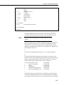
2.1 Setting the SDM Address
The 4 x 2-way block of jumpers close to the ‘D’ connectors selects the SDM
address of the SDM-SIO4. This address ranges from 0 to 15. The four selector
blocks are numbered on the PCB silk screen as 1, 2, 4, and 8; ‘8’ is closest to
the ‘D’ connectors. This is in binary format as shown in Table 2-1.
TABLE 2-1. Address Settings
Selector Block Settings
8
4
2
1
0
0
0
0
0
0
0
0
1
1
1
1
1
1
1
1
0
0
0
0
1
1
1
1
0
0
0
0
1
1
1
1
0
0
1
1
0
0
1
1
0
0
1
1
0
0
1
1
0
1
0
1
0
1
0
1
0
1
0
1
0
1
0
1
SDM Address
0
1
2
3
4
5
6
7
8
9
10
11
12
13
14
15
NOTE: A ‘1’ means the selector block shorts both pins. ‘0’ means the selector
is only connected to one pin (for storage).
2-1
Section 2. Installation and Hardware Set-Up
2.2 Selecting RS232 or 5V Logic for Each Port
The output voltage levels of each serial port can be set to either:
• Logic level output: +5V (high) / 0V (low) or
• RS232 output:
+5V (high) / -5V (low) (compatible with RS232 driver
requirements).
The logic level output is used when driving a logic level compatible device, e.g.
an SC32A, or where quiescent current is a concern. This mode is lower power
because the idle state is 0V, while the idle state of the RS232 output is -5V
which results in current flow to ground via the input resistance of the RS232
device’s inputs. However, in practice, this logic level output mode can be used
with the majority of RS232 sensors as most accept a logic level drive signal as
a valid input signal.
The output levels are configured via a 4 x 3-way block of jumpers at the back
of the unit. There is one jumper for each port. Text is printed on the circuit
board to indicate the port and the relevant position for the two modes. If the
jumper is fitted on (shorts) the two pins close to the right hand side of the unit,
the port will be in RS232 mode and if the two pins close to the left hand side
are shorted, the port is set to 5V logic.
The inputs to the SDM-SIO4 are compatible with either logic level or RS232
signals.
2.3 Connections to the SDM-SIO4
Connect the SDM port to the datalogger SDM terminals as described under
‘SDM Port’ in Section 1. Use a short, low-capacitance, screened cable. The
12V supply can normally be taken from the 12V supply input to the datalogger.
Make up cables for the RS232 devices to match the connections shown under
‘SDM-SIO4 Port’ in Table 1-1 (Section 1). Please refer to your sensor manual
for a description of the required connections, including the handshaking
requirements. To minimize susceptibility to noise, use screened connectors and
cables.
2.3.1 Transient Protection and Grounding
The G terminal on the SDM-SIO4 acts both as a ground reference point for
digital communications via the SDM port and also as a protective ground for
the SDM-SIO4. Usually it can be connected back to the datalogger power
ground (G on a CR10/10X). This ground in turn should be connected to the
safety ground for the whole system.
The SDM-SIO4 has protection against electrostatic discharge and induced
transients on all input and output lines. However, the level of protection offered
is limited by the grounding paths within the case. Where long cables are to be
run to remote serial devices, especially in areas prone to lightning, external
2-2
Section 2. Installation and Hardware Set-Up
lightning protection is recommended on all lines connected to the serial ports
(contact Campbell Scientific for further details).
The possibility of ground loops being set up between the datalogger and the
remote RS232 device via the serial cable should also be considered. Ground
loops formed by secondary return earth paths can lead to various problems
including:
• Electrical noise causing possible loss or corruption of serial data.
• Electrical noise being transferred back to the datalogger causing errors on
analogue measurements.
• Long term damage in the form of corrosion caused by current flowing along
electro-chemical gradients.
If it is not possible to prevent a ground loop, or if electrical noise is found to be
a problem, it may be necessary to add an opto-isolated interface to the output of
the SDM-SIO4 serial port. Please contact Campbell Scientific for further
details.
Even if ground loops can be prevented, the length of cables that can be used for
RS232 signals is limited to a few tens of meters (the exact length depending on
the RS232 driver hardware and the cable used). Short-haul modems can be
added to the SDM-SIO4 to allow cables up to several kilometers to be used and
in addition providing ground isolation (please contact Campbell Scientific for
further details).
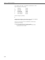
2.4 Power-on Tests — the Status LED
When the SDM-SIO4 is powered up or has been reset by the internal watchdog
hardware it flashes the red LED on the front panel in the following way to
indicate status:
TABLE 2-2. Status LED Error Codes
No. of Flashes
Description of error/status.
1
2
3
SDM-SIO4 is working correctly.
SDM-SIO4 EPROM signature failure.
SDM-SIO4 internal battery must be replaced.
NOTE 1: The LED flashes for 1 second on and 1 second off. The LED will
also illuminate when the front panel switch is pressed.
NOTE 2: The LED may take up to 4 seconds before it flashes after power up.
2-3
Section 2. Installation and Hardware Set-Up
This is a blank page.
2-4
Section 3. Understanding How the
SDM-SIO4 Handles Data
For simple applications the SDM-SIO4 can be configured and controlled from the
datalogger alone, using the datalogger program instruction P113 (CR10X and CR7
dataloggers only). Future developments will include support for other dataloggers.
More complicated applications require configuration of the SDM-SIO4 using the
‘command line’ function on a PC running a terminal emulator. This allows you to set up
mechanisms to control the transmission of long, formatted output data and filtering of
numerical values out of received data. This is done by storing the detailed formatting and
filtering configurations in the SDM-SIO4 (see the section about the command line mode
below).
Thus when the datalogger needs to send out long or complicated data strings it only needs
to send a short command to the SDM-SIO4 to tell it to do this, i.e. it does not have to pass
the whole string via the SDM interface. Likewise, by telling the SDM-SIO4 how to process
received data, it can strip off the unwanted characters and reduce the data to either binary
or floating point numbers. This minimizes the time it takes for the datalogger to get the
data and so allows the datalogger to load the data values into its memory with minimal
processing.
3.1 Introduction
For collection of data from an intelligent sensor the datalogger programming is
typically broken down into several steps, which might be:
1. Set up and configure the serial ports, e.g. baud rate, parity, handshaking.
This can be done by one call of the datalogger instruction either at program
compilation (so it is done only once) or perhaps in a subroutine which is
called when a flag is toggled.
2. Use a second call of the instruction to tell the SDM-SIO4 to send out a
string to request data from a sensor and to tell it how to process the returned
data.
3. At some point later in the program use a third call to collect the preprocessed data from the SDM-SIO4.
Before examining the detail of the datalogger instruction it is necessary to
understand the data output formatter and the input filters. These work in
principle (and in certain details) like the formatting and filtering options used to
write and read data from files in some high-level programming languages.
3.1.1 Method of Entering Special / Control Characters
Before going on to discuss filters, you should understand how to enter special /
control characters.
3-1
Section 3. Understanding How the SDM-SIO4 Handles Data
To enter a control character in the range of 0-255 decimal in a filter string,
formatter string or a user string you must use the ‘&hh’ format, where ‘&’
defines the following two characters, ‘hh’, to be a hexadecimal number between
00 and FF. For example, ‘&de’ would be character 222 decimal. To use ‘&’
within the string you must type ‘&&’ (i.e. && = & when in a string).
NOTE
The hex. number must always be two ASCII characters.
Control characters can be entered for all commands in a similar way:
• ^M is carriage return, ^J line feed etc.
• ^^ means ^
• "" means "
• ]] means ]
• && means &
• &0d means line feed
• &hex,hex used to enter 2-character hex. codes (0-9, A-F)
3.2 Input Filters
Input filters are used to convert received data into a form that is easy for the
datalogger to process. Filters are generally used to strip out the required values
from other, unnecessary, data transmitted from the sensor/device. The filters
will also convert the required data into a form that the datalogger can use.
For example, the sensor may output the (unusual) complex string ‘Sample data
+12.3, 23.567,0xAB,12.4’. From this string you may only require to record the
hexadecimal number 0xAB. A filter can be set up to strip out only this number,
and then convert it to a 4-byte floating point number which the datalogger can
use. The datalogger will then collect this value and place it into an input
location –in this case as 171 decimal.
NOTE
You must always set up a filter if you want the datalogger to
collect data from the SDM-SIO4.
3.2.1 Filter Types
Simple Filters
These filters can be set up by the datalogger program, i.e. command line set-up
is not necessary. The four filters search for a specific data type to convert to
Campbell Scientific floating point format. The SDM-SIO4 continues searching
and reading data until it encounters a termination character (if this has been
specified in Instruction 113) The filters are as follows:• Search for an ASCII floating point number to convert to Campbell
Scientific floating point format.*
3-2
Section 3. Understanding How the SDM-SIO4 Handles Data
• Search for an ASCII hex pair to convert to Campbell Scientific floating
point format.*
• Search for an 8-bit binary number to convert to Campbell Scientific floating
point format.
• Search for a 16-bit binary number to convert to Campbell Scientific floating
point format.
* Non-numeric characters are ignored.
See Section 5 – ‘Programming the Datalogger’.
Filter Strings
These are used to define how to filter incoming data from a port into a format
the datalogger can use. This is done by having a user-defined filter string prestored in the battery-backed memory of the SDM-SIO4. These strings have to
be created via the command line (see Section 4), in a similar fashion to the
format strings. The filter commands are as follows:
• An Define a filter time-out. The range is from 0 to 255 in 50ms steps,
giving a range of 0 to 12.75 seconds. The accuracy is -50ms +0ms so an
‘n’value of 1 is not practical as the time-out could be between 0 and 50ms.
This filter type can be put anywhere in the string. If a time-out occurs before
the entire filter is complete, any data already processed is disregarded and
the filter is restarted. When the filter string is finished the time-out is
stopped and set to zero. If n=0 then this stops the time-out and the filter will
operate with no time-out. While the time-out is active the SDM-SIO4 will
not shut down into the low power state unless the filter is complete or the
time-out has finished. Note it best to start the time-out after a trigger
command.
• B[n,n,n,...]
Carry out a bit field to floating point conversion. The
SDM-SIO4 gets or waits for as many bytes as are required to fulfil the total
number of bit fields. ‘n’ can be any number of bits from 0 to 255, but more
than 23 bits is beyond the floating point range of the datalogger so the value
returned to the datalogger will be invalid. There can be any number of bit
fields, only limited by the command line buffer and the 255-byte limit for
string storage. If there is part of a byte unconverted and there are no more
bit fields remaining then those bits are discarded.
• bn A binary number should be at this position. The SDM-SIO4 converts
‘n’ bytes (1, 2 or 3 bytes) to Campbell Scientific floating point.
• C
Discard one byte (character).
• c
Read one byte (not converted to Campbell Scientific floating point).
• D
A signed integer should be at this position. If it is found, the signed
integer is sent to the datalogger and removed from the buffer. If no signed
integer is found, the SDM-SIO4 sends -99999 to the datalogger.
• d
Search for a signed integer indefinitely, skipping non-numeric
characters.
3-3
Section 3. Understanding How the SDM-SIO4 Handles Data
• e[ ] Scan until any ASCII character not entered between the brackets is
encountered. The maximum number of non-trigger characters is 255. Note
that this filter does not remove the non-matching character from the buffer.
• F
A floating point number should be at this position. If it is found, the
signed floating point number is sent to the datalogger and removed from the
buffer. If no floating point number is found, the SDM-SIO4 sends -99999 to
the datalogger.
• f
Search for a floating point number indefinitely, skipping any nonnumeric characters.
• gn Error detection – start of signature calculation for received data – see
Section 6.
• Gn Error detection – marks end of signature calculation for received data
– see Section 6.
• i[ ] Scan until any ASCII characters entered between the brackets are
encountered. The maximum number of characters between the brackets is
255. Note that this filter does not remove the matched character from the
buffer.
• Jx:y ‘J’ deals with signed and unsigned integers,
‘x’ is the number of characters or digits per integer (1 to 255) and y is the
number of repetitions (1 to 255).
Leading spaces and the signs ‘+’ and ‘-’ are allowed before the number but
any integer which contains non-numeric characters (e.g. 23A5) will
produce an error and return -99999.
• nn
Discard ‘n’ bytes. ‘n’ can be in the range of 0-255.
• Nn Read ‘n’ bytes. ‘n’ can be in the range of 0-255 (not converted to
Campbell Scientific floating point).
• pn Hexadecimal byte should be here, n=number of bytes to convert (n=1
to 3 hex pairs) to Campbell Scientific floating point.
• Pn Converts hexadecimal value(s) to Campbell Scientific floating point
format. n=1,2,3 number of hex. pairs to convert into value LSByte first.
• rn
Send the byte received to port ‘n’ for re-transmission. ‘n’ can be
1-4. The byte is removed from the receive buffer.
• s
Stop the filter until commanded by the datalogger to restart.
• t[ ] Search for an exact string match between the [ ]. All ASCII characters
up to and including the matching string are removed from the receive buffer
before the next filter type starts.
• T[ ] Search for an exact string match between the [ ]. All ASCII characters
up to the matching string are removed from the receive buffer before the
next filter type starts. (Same as t[ ], except matching strings are not
removed).
• u[ ] Convert ASCII floating point into Campbell Scientific floating point
format until the termination character/string between [ ] is seen. The
termination character is removed from the buffer.
3-4
Section 3. Understanding How the SDM-SIO4 Handles Data
• vn[ ] Convert ‘n’ ASCII hex pairs into Campbell Scientific floating point
format until the termination character/string between [ ] is seen. ‘n’ can be
1-3. The termination character/string is removed from the buffer.
• Vn Searches for hexadecimal value(s) and converts them to Campbell
Scientific floating point format. Terminates when a string between [ ] is
seen. n=1,2,3 number of hexadecimal pairs to convert into value LSByte
first.
• wn[ ] Convert ‘n’-byte binary data into Campbell Scientific floating point
format until the termination character/string between [ ] is seen. ‘n’ can be
1-3. The termination character/string is removed from the buffer.
• Wn Searches for binary value(s) and converts them to Campbell Scientific
floating point format. Terminates when a string between [ ] is seen. n=1,2,3
number of hexadecimal pairs to convert into value LSByte first.
• x
This marks the start of a data set. A data set is a set of converted data
for the datalogger to collect. When this filter type is used the data in the
data set is only available to the datalogger when all parts of the data set
have been converted – see ‘X’, below.
• X
This marks the end of a data set. This makes the data converted in the
data set available to the datalogger. This also means that data after this is
available to the datalogger as soon as the SDM-SIO4 has converted each
value. If the end of the data set is at the end of the filter string then this filter
is not required as the end of the filter string is always the end of a data set.
• Yn Converts binary value(s) to Campbell Scientific floating point format.
n=1,2,3 number of bytes to convert into value LSByte first.
• z
Flush the UART FIFO (serial port hardware buffer) and the Receive
buffer associated with the port that is using this filter type. This does not,
however, clear the converted data buffer.
As an example, take the following sensor output string:
battery 12.65V,current 12mA
The filter string might be:
i[b]n8Fi[c]n8F
Output to the datalogger would be 12.65 and 12 as Campbell Scientific floating
point numbers. This filter string works as follows:
1. i[b] waits for the trigger character ‘b’ of ‘battery’.
2. n8 discards everything up to 12.65V.
3. F converts the number to Campbell Scientific floating point. If a valid
number is not found -99999 is sent to the datalogger.
4. i[c] waits for the trigger character ‘c’ of ‘current’.
5. n8 discards everything up to 12mA.
6. F converts the number to Campbell Scientific floating point. If a number is
not found -99999 is sent to the datalogger.
This filter will repeat the above operations on all incoming values.
3-5
Section 3. Understanding How the SDM-SIO4 Handles Data
Predefined Filter Strings
A small number of fixed filter strings are pre-defined as follows:
Filter No.
Filter String Used
256
257
258
259
r1
r2
r3
r4
3.3 Output Formatting
The output formatters are used to format data from the datalogger into English
text messages, send strings/commands to sensors and to output text to a display.
For example, you may have a display on which you want to show air
temperature and humidity. The datalogger would take the measurements from
the sensors, and place two values into appropriate input locations. It would be
impractical for the datalogger to store text labels in this way, and so you could
use the SDM-SIO4 to send a label to the display along with the data from the
datalogger.
The final result may be displayed as:
The temperature is 23.7C
The humidity is 65.8%
The string generated would then be transmitted from the selected serial port.
Because the formatter is programmable, almost any string can be output from
the serial port, either by programming the datalogger or by using the command
line.
3.3.1 Simple Output Formatter
This can be set up by the datalogger and allows data to be transmitted out of the
SDM-SIO4 in a number of simple formats. It is not necessary to use the
command line mode to use these formats. Simple output formats are as follows:
• Convert a location sent into ASCII floating point. If this option is selected
an extra ASCII character/delimiter can be added to the end of the ASCII
number sent.
• Convert a location sent into an ASCII hex pair. If this option is selected an
extra ASCII character/delimiter can be added to the end of the hex number
sent.
• Convert a location sent into an 8-bit binary byte. If this option is selected an
extra ASCII character/delimiter can be added to the end of the byte sent.
• Convert a location sent into a 16-bit binary word. If this option is selected
an extra ASCII character/delimiter can be added to the end of the 16-bit
word sent.
See Section 5 – ‘Programming the Datalogger’.
3-6
Section 3. Understanding How the SDM-SIO4 Handles Data
3.3.2 Output Format Strings
These allow either just long strings to be sent from the SDM-SIO4 or a
combination of string data plus data from a datalogger input location. This type
of format is normally set up from the ‘command line’. The user definable
strings are referenced by a number in the range 0..255. The string is entered as
a series of the following formatter commands:
• <space> Send ASCII space.
• bn
be
Send a binary number received from the datalogger to the port. ‘n’ can
1, 2 or 3 bytes, i.e. 8-, 16- or 24-bit. If n=4 then it is direct Campbell
Scientific floating point format. If the formatter string asks for more
values than the datalogger sends then the SDM-SIO4 sends ‘*’
characters.
• fn:n Send a left-hand justified, formatted ASCII floating point number to
the port. The first ‘n’ is the field width in characters and the second ‘n’
is the number of decimal places to use within the field width. If the
integer part of the ‘n’
number is bigger than the field width, the
SDM-SIO4 still sends it even though it is longer than the set field
width. If the formatter string asks for more values than the datalogger
sends (because Instruction 113 specifies
fewer values) then the
SDM-SIO4 sends a number of ‘*’ characters to the port (e.g. for a
field width of 4 it sends ****). Minimum field width 2 digits,
maximum field width 15 characters, maximum number of decimal
places 8.
• gn Error detection – start of signature calculation for transmitted data –
see Section 6.
• Gn Error detection – marks end of signature calculation for transmitted
data – see Section 6.
• hn
‘*’
Send an ASCII hex number to the port. ‘n’ can be 1, 2 or 3 bytes
converted, i.e. an 8-, 16- or 24-bit number. If the formatter string asks
for more values than the datalogger sends then the SDM-SIO4 sends
characters.
• i[ ]
Send the string between the brackets [ ] to the port. Up to 255 ASCII
characters can be sent. (See Section 4.2 – Entering Commands).
• J
Send line feed.
• M
Send carriage return.
• s
Stop formatting.
• zn Send a pre-stored string to the port. ‘n’ is the user-defined string
number
0-255 or a fixed string 256-511.
Table 3-1, below, shows all the defined Fixed Strings.
3-7
Section 3. Understanding How the SDM-SIO4 Handles Data
TABLE 3-1. Fixed Strings Currently Allocated
String number
String (enclosed in quotes)
256
257
258
259
260
261
262
263
264
265
266
267
268
269
270
271
272
273
‘+0000000000123.45670000000000CrLf’
‘Voltage’
‘Amps’
‘Watts’
‘Joules’
‘Temperature’
‘Pressure’
‘Speed’
‘Power’
‘Depth’
‘Length’
‘Height’
‘Enter’
‘Password’
‘Correct’
‘Incorrect’
‘Overrange’
The ASCII characters: carriage return, linefeed.
If the datalogger sends more data than is defined in the SDM-SIO4’s formatter
string, the SDM-SIO4 starts at the beginning again unless ‘s’ (stop formatting)
is used, in which case any extra data within that transmission is ignored.
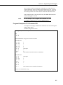
CR10X Program Example
This program example will output the battery voltage and panel temperature
received from the datalogger input locations to port 2 on the SDM-SIO4, using
the SDM-SIO4 Output Formatter.
The user defined format string, which is entered in the command line mode (see
Section 4), is as follows:fmtst 123 "z261 f6:2 i[Battery ]z257 f6:1z273"
Typical example output from this formatter string is:Temperature 27.23 Battery Voltage 12.6
Here is a description of what each part of the formatter does:fmtst 123 – This is the command word for storing the formatter string in area
123.
z261 – This outputs the fixed string ‘Temperature’.
space – This outputs an ASCII space.
f6:2 – This takes the value from location 1 and outputs it in a field with a total
width of 6 characters. There are 2 decimal places available within the field.
space – This outputs an ASCII space.
3-8
Section 3. Understanding How the SDM-SIO4 Handles Data
i[Battery ] – This outputs the word between the brackets [ ].
z257 – This outputs the fixed string ‘Voltage’.
space – This outputs an ASCII space.
f6:1 – This takes the value from location 2 and outputs it in a field with a total
width of 6 characters. There is 1 decimal place available within the field.
z273 – This outputs the fixed string ‘CrLf (carriage return line feed)’.
*Table 1 Program
01: 2
Execution Interval (seconds)
;get battery voltage.
1: Batt Voltage (P10)
1: 2
Loc [ Batt_v
]
;get panel temperature.
2: Internal Temperature (P17)
1: 1
Loc [ Temp_C
]
;send battery voltage and temperature to port 2 on the SDM-SIO4.
3: SDM-SIO4 (P113)
1: 1
Reps
2: 0
Address
3: 2
Send/Receive Port 2
4: 2304
Command
5: 9123
1st Parameters
6: 0
2nd Parameters
7: 2
Values per Rep
8: 1
Loc [ Temp_c ]
9: 1.0
Mult
10: 0.0
Offset
;see Section 5 for explanation of
;Command 2304 and its Parameters
;
*Table 2 Program
02: 0.0000
Execution Interval (seconds)
*Table 3 Subroutines
End Program
3-9
Section 3. Understanding How the SDM-SIO4 Handles Data
This is a blank page.
3-10
Section 4. Programming the SDM-SIO4
This section gives both the basic commands and advanced command line options which
allow testing and advanced configuration of the SDM-SIO4.
4.1 Command Line Operation and Structure
To use the command line mode, connect a computer to port 1 of the SDMSIO4. The computer should run a terminal emulation program (e.g.
GraphTerm) which is set to 9600 baud, 8 data bits and 1 stop bit. If connecting
to a PC you will need a null modem cable.
When the computer is connected, the command line can be made active by
pressing the small momentary push-button switch, next to the Status LED.
When this happens the SDM-SIO4 prompt ( SDMSIO4->) is sent out of port 1.
At this prompt a number of commands can be typed and executed.
• The command line buffer is 512 bytes long so no command with parameters
must be longer than this.
• After ten minutes of inactivity (where no valid commands are executed) the
command line mode will time out and port 1 will return to its normal
function.
• The command line mode can be activated while the datalogger is running a
program which communicates with the SDM-SIO4. However, all
datalogger activity related to port 1 is ignored.
• Complicated or long string definitions are best set up by editing a text file
which includes the string definition commands. This file can then be sent
out to the SDM-SIO4 once it is configured in the command line mode. The
SDM-SIO4 can accept multiple configuration strings sent within one file.
NOTE
By using (datalogger) Instruction P113 Command 321 it is
possible to execute a command line command from a datalogger
program. See Section 5 of this manual for further details.
4.2 Entering Commands
A command is executed when a carriage return (CR) is sent. This is normally
sent by pressing the ENTER key on a computer. The method of entering control
characters was discussed in Section 3.1, but is repeated here for convenience.
To enter a control character in the range of 0-255 decimal in a filter string,
formatter string or a user string you must use the ‘&hh’ format, where ‘&’
defines the following two characters, ‘hh’, to be a hexadecimal number between
00 and FF. For example, ‘&de’ would be character 222 decimal. To use ‘&’
within the string you must type ‘&&’ (i.e. && = & when in a string).
4-1
Section 4. Programming the SDM-SIO4
NOTE
The hex. number must always be two ASCII characters.
Control characters can be entered for all commands in a similar way:
• ^M is carriage return, ^J line feed etc.
• ^^ means ^
• "" means "
• ]] means ]
• && means &
• &0d means line feed
• &hex,hex used to enter 2-character hex. codes (0-9, A-F)
4.3 Basic Commands
fltst [string number] ["filter definition"]
This command stores a filter definition to a string number 0..255.
Example: fltst 22 "ccci[x]Fs"
The above example stores the filter definition in filter string 22.
See Section 3 for filter types.
strst [string number] ["string definition"]
This command stores a user text string definition to a string number 0..255.
Example: strst 22 """This is a string""^M^J"
The above example stores the string definition "This is a string"crlf in string 22.
This string will include the two quotation marks, as shown.
fmtst [string number] ["format definition"]
This command will store a formatter definition to a string number 0..255.
Example: fmtst 22 "i[volts=]f4:2" (result would be, for example,
volts=12.7)
The above example stores the formatter definition in string 22.
See Section 3 for formatter types.
strdelete [string number]
This command deletes a stored filter, formatter or text string 0..255 from
memory.
4-2
Section 4. Programming the SDM-SIO4
strrd [string number]
This command outputs the stored string or definition 0..255 to the command
line.
NOTE
1. When string definitions are stored, all control characters are
converted and so the string may not be identical to the one
you typed in.
2. Formatter and filter strings cannot be read by this command
because they are compiled.
exit
This command exits the command line and returns port 1 of the SDM-SIO4 to
normal operation.
4.4 Advanced Commands
version
This returns the internal EPROM part number, signature and the string
signature if good or 0 if bad. This will give the same signature as Campbell
Scientific’s SIG.COM PC program.
portset [port#] [baud#] [data length] [stop bits] [parity] [handshake
mode] [delay]
This sets up the port 1..4 to the communication format you require.
‘port #’ means the port number (1..4) to set up. For details of the other
parameters (baud #...delay) see Appendix B.
reset
The SDM-SIO4 is set to a known default state. All strings, filters and
formatters are erased, ports are set to 9600 baud, 1 stop bit, no parity and no
handshake. All transmit and receive buffers are flushed. All error counts are
zeroed.
ramtest
The system RAM is tested and the SDM-SIO4 is then reset. The string ‘Ram
test pass’ is returned if the RAM is OK or ‘Ram test fail’ if some part
of the memory failed.
changeport [port #]
This command changes the port for which the command line is available. This
command line port setting will stay in effect for further sessions until a new
4-3
Section 4. Programming the SDM-SIO4
port is chosen or power is removed and then re-applied, in which case the
command line reverts to port 1.
status
This outputs the general status of the SDM-SIO4. The results are as follows:
BATT 0 or 1
If the value is 0 the battery needs replacing.
If the value is 1 the battery is good.
ADDR 0 to 15
This is the current SDM-SIO4 hardware address.
WD n WDERR n WDADDR n
WD n is a count of the number of watchdog resets, WDERR is the number of
the last task that crashed and WDADDR is the address at which the crash was
found.
NC 0-9
This is the number of SDM commands the datalogger sent to the SDM-SIO4
that the SDM-SIO4 did not recognize. This counter may be incremented when
the program is first compiled in the datalogger due to the auto speed detection
of the datalogger.
PORT1-4
These four sets of values are the current port settings in the order as below:
• Baud rate setting
• Data length setting
• Stop bit setting
• Parity bit setting
• Handshake mode
• Delay time value
• Parity error count
• Framing error count
• Overrun error count
• Line break error count
• DTR handshake line status, 0=low 1=high
• RTS handshake line status, 0=low 1=high
• CTS handshake line status, 0=low 1=high
• DSR handshake line status, 0=low 1=high
• DCD handshake line status, 0=low 1=high
You should refer to the appropriate section of this manual for further specific
detail.
4-4
Section 4. Programming the SDM-SIO4
hexdump [start address] [number of bytes]
This is used by Campbell Scientific for test purposes and outputs a hex dump of
the SDM-SIO4’s internal address space. The start address and number of bytes
to dump must be in base 10, decimal integer.
lasterror
This command returns the last reported error to the command line. This
command can be used, for instance, to get the return code from the ramtest
command when in talk-through mode.
errorres
This resets all error counters.
bytewr [address] [byte]
This is used by Campbell Scientific for test purposes and writes a byte to the
memory of the SDM-SIO4.
The address and bytes to write must be in base 10, decimal integer. The address
range is 0-65535 and the byte is from 0-255.
testio [test#]
This is used by Campbell Scientific for test purposes.
Each test command is carried out for 2 seconds. Test# can be in the range 0255; only five test numbers are currently valid, as shown below.
testio
returns
test 0
DTR,RTS,IO=LOW
test1
DTR=HIGH,RTS,IO=LOW
test2
DTR=LOW,RTS=HIGH,IO=LOW
test3
DTR,RTS=HIGH,IO=LOW
test4
DTR,RTS=LOW,IO=HIGH
4-5
Section 4. Programming the SDM-SIO4
This is a blank page.
4-6
Section 5. Programming the Datalogger
The datalogger instruction specific to the SDM-SIO4 is P113 (CR7 and CR10/10X only).
(Please check with Campbell Scientific to see if your version of the operating system
supports this.) The instruction has the following format:
Parameter No.
Description
01
02
03
04
05
06
07
08
09
10
Reps (number of adjacent addressed SDM-SIO4s)
Address of SDM-SIO4 (0..15)
Mode (0..5)
Command (0..9999).
First command option (0..9999)
Second command option (0..9999)
Values per rep
Starting input location
Multiplier
Offset
5.1 Instruction 113 Parameters
5.1.1 Parameter 1 — Reps
This specifies the number of times you wish this command to repeat for each
SDM-SIO4 connected to the datalogger with sequential addresses. This will
normally be set to one.
5.1.2 Parameter 2 — Address
This is the address of the SDM-SIO4 that the instruction applies to.
See Section 2 – ‘Installation and Hardware Set-Up’ for information on setting
the SDM-SIO4 address
5.1.3 Parameter 3 — Mode
This defines which port the command applies to:
Code
1
2
3
4
5
Port
Send/Receive port 1
Send/Receive port 2
Send/Receive port 3
Send/Receive port 4
Send to all four ports (global)
5-1
Section 5. Programming the Datalogger
5.1.4 Parameters 4, 5 and 6 — SDM-SIO4 Command
This command (with up to two options) defines exactly what the instruction
will do. Where no options are needed, enter values of 0000 for parameters 5
and 6.
5.1.5 Parameter 7 — Values per Rep
This determines how many values to send or receive, starting from the specified
input location (parameter 8). Data can be either 4-byte floating point values or
single bytes, determined by the SDM-SIO4 command number.
Some commands require no input or output of values; for these commands this
parameter would be set to zero.
5.1.6 Parameter 8 — Starting Input Location
This is the first input location that values will be sent from or written to
consecutively until all values per rep (parameter 7) are done.
5.1.7 Parameters 9 and 10 — Multiplier and Offset
The multiplier and offset are applied to all incoming and outgoing data.
NOTE
The multiplier should normally be set to 1.000; if left at 0.000
then zero value data will be stored.
5.2 Commands and Options (Parameters 4, 5 and 6)
For many of the command options listed below, it is necessary to leave a small
delay before calling another instance of the instruction which communicates
with the SDM-SIO4. This is required to allow the SDM-SIO4 to process the
instructions it has been given. Failure to allow these delays will probably cause
the SDM-SIO4 to return invalid data. The delays are called ‘Minimum delay’ in
the command descriptions.
Many of the delays vary with the parameters of the instruction, in which case a
formula is quoted to enable you to calculate the delay. All delays are in
milliseconds. The notation used in the formula is:
• floats is number of locations to convert.
• characters is the number of characters to each float value including decimal
point and sign.
• ports is the number of ports the value or values are being transmitted from.
This is 1 if parameter 3 in P113 is 1..4 or 4 if parameter 3 is 5.
5-2
Section 5. Programming the Datalogger
NOTE
The delay required in the program can either be forced using
Instruction P22, or by using the time to execute other
measurement or processing instructions.
5.2.1 Understanding Parameter Options and Returned Values
NOTE
In the following examples, ‘x’ indicates a single digit from 0 to 9.
When the command requires or returns values, each digit, or combination of
digits, can signify either a value, flag or setting.
Using Command 5 as an example:
Number of watch dog resets
| | Number of invalid commands executed
| | | Lithium battery level
| | | |
x x x x
The first value returned by Command 5 indicates:
• Actual number of watch dog resets (two digits 00 to 99) – a value.
• Number of invalid commands executed (single digit 0 to 9) – a value.
• Level (state) of the lithium battery (0=low, 1=good) – a flag.
If the value returned was, for example, 1281, then it would have the following
meaning:
12 watch dog resets
8 invalid commands
1 battery level good
The second value returned shows whether or not data is available from a
specific port. A non-zero digit indicates that data is available, whereas a zero
signifies that no data is available.
Command 5 is explained in detail later.
NOTE
When a command parameter requires values to be entered (e.g.
Command 1026), it is a good idea to always enter all four digits.
Only trailing zeros are significant to the SDM-SIO4, and so
entering 0001 or 1 would be identical. However, if the first
parameter needs to be 1, you must enter 1000. The habit of
always entering all four values helps to minimize input errors.
5.2.2 Command 1: Poll of Available Data
This command has no additional options after the command. The SDM-SIO4
returns one Campbell Scientific floating point number to indicate if data is
available as below:
5-3
Section 5. Programming the Datalogger
Port 4 data available
| Port 3 data available
| | Port 2 data available
| | | Port 1 data available
| | | |
x x x x
If any of these four digits is greater than zero then data is available.
Values per repetition = 1
5.2.3 Command 2: Signatures
This command gets the SDM-SIO4 EPROM signature and the string memory
area signature; the two values are written into consecutive input locations. If the
signatures are zero then there could be corrupt data.
Values per repetition = 2
5.2.4 Command 3: Flush all Receive Buffers
Stored data in the SDM-SIO4 relevant to the port is also erased with this
command.
Values per repetition = 0
5.2.5 Command 4: Send Data to Datalogger
This command requests the SDM-SIO4 to send the specified (values/reps)
number of floating point values it has already received from the RS232 device
(relevant to the port specified) into input locations. -99999 is stored if no value
is available.
For example, this command could be used to get data converted using input
filter strings of type d, D, f, F, pn, bn, u[ ], vn[ ], wn[ ] and B[n,n..] – see
Section 3.
5.2.6 Command 5: Status
This command returns the SDM-SIO4 general status, lithium battery level,
errors and data available flags. The data is supplied as two floating point
values. First value:
Number of watch dog resets
| | Number of invalid commands executed
| | | Lithium battery level
| | | |
x x x x
Number of watch dog resets: This is a count from 0 to 99. This indicates that
there has been some hardware or software failure, or can be caused by the
datalogger transmitting the correct address but not transmitting any commands.
5-4
Section 5. Programming the Datalogger
Number of invalid commands executed: This is a count from 0-9 and indicates
that the command you have tried to execute is not a current SDM-SIO4
command. Because some dataloggers carry out auto speed detection for the
SDM interface, this counter may be incremented when the program is first
compiled.
Lithium battery level:
0
Lithium battery low and must be replaced.
1
Lithium battery good.
The second floating point value is the same as for Command 1:
Port 4 data available
| Port 3 data available
| | Port 2 data available
| | | Port 1 data available
| | | |
x x x x
If any of these four digits is greater than zero then data is available.
Values per repetition = 2
5.2.7 Command 6: Flush Transmit Buffer
This command flushes the SDM-SIO4 transmit buffer of data it is waiting to
send.
Values per repetition = 0
5.2.8 Command 7: Activate Command Line
This command simulates pressing the push button on the SDM-SIO4 which
activates the command line mode on the port determined by the mode. If the
mode parameter of P113 is 0, the command line will be on the currently defined
port. If the parameter is 1-4, then the command line will be on the port number
specified.
Values per repetition = 0
5.2.9 Command 8: Poll Tx Buffers for Data
This command polls the Tx buffers to see if they have data.
This command has no additional options after the command. The SDM-SIO4
returns one Campbell Scientific floating point number to indicate if it has data
as below:
Port 4 has data
| Port 3 has data
| | Port 2 has data
| | | Port 1 has data
| | | |
x x x x
5-5
Section 5. Programming the Datalogger
If any of these four digits is greater than zero then the buffer has data.
Values per repetition = 1
5.2.10 Command 9: Flush Converted Data Buffer
This command flushes the converted data buffer of data that is available for the
datalogger to collect.
Values per repetition = 0
5.2.11 Command 66: Send Single-Byte Data to Datalogger
This command requests the SDM-SIO4 to send single-byte binary data, which is
written one byte per location for all values/rep. If no data is available then the
digit 255 is stored in the input location. This command could be used, for
example, to get data from filter strings of type c (read any byte) and Nn (read ‘n’
bytes) – see Section 3.
5.2.12 Command 67: Get Return Code
This command gets the return error code and places it into a specified location.
Command 67 is used in conjunction with command 321 and provides a single
return code value which indicates if the command was successful or not. See
Section 5.6 for the return codes.
Values per repetition = 1
5.2.13 Command 320: Send Byte Data to SDM-SIO4
This command transmits bytes of data (one per input location) to the SDMSIO4 for retransmission. The values in the input location should be in the range
0..255.
5.2.14 Command 321: Execute Command Line Command
By using P113 command 321 it is possible to execute a command line
command from the datalogger program. This is done by loading the
datalogger’s input locations with exactly the same string of characters that you
would use to execute a real command line command, except you would have to
enter the character codes in sequential locations. The P113 command 321
would then load the string into the SDM-SIO4 and execute the command. The
321 command is useful for reconfiguring a remote SDM-SIO4 as changes can
be made by downloading programs (using the 321 command) which can change
the SDM-SIO4 setup.
The datalogger can send other commands to the SDM-SIO4 while the
command line command is executing.
Any command line command executed from the datalogger can only return a
single return code value to indicate if it was successful or not, and any other
output which that command would normally produce is lost. This means that
5-6
Section 5. Programming the Datalogger
there would be no point executing some commands, for example STATUS,
from the datalogger, as there would be no status output to be seen. To get the
return code you can use the P113 Command 67 which will put the return code
into a storage location. The return codes are listed at the end of this section.
This command requires a 4ms delay before any other SDM-SIO4 instruction
from the datalogger is executed
NOTE
Do not attempt to run a program with command 321 while
accessing the command line via one of the SDM-SIO4 ports.
Program Example for P113 Command 321
An example of executing a command line command to store the following filter
string as shown below:
The filter string is fltst 25 “ffCc”
;test flag one. If clear then set-up the SDM-SIO4.
P91
1:
2:
21
30
;load command line string into consecutive locations.
P65 Bulk load
1: 102
2: 108
3: 116
4: 115
5: 116
6: 32
7: 50
8:5 3
9: 1
P65 Bulk load
1: 32
2: 34
3: 102
4: 102
5:6 7
6: 99
7: 34
8: 0
9: 9
f
l
t
s
t
ascii space
2
5
First location to store the first lot of 8 characters.
ascii space
“
f
f
C
c
“
First location to store second lot of characters.
;execute the command line string.
5-7
Section 5. Programming the Datalogger
P113
1:
2:
3:
4:
5:
6:
7:1
8:
9:
10:
1
0
1
21
0
0
5
1
1
0
Command to execute command line command.
Length of command line string. ;no. of datalogger input locations
;delay large enough (10ms) to allow SDM-SIO4 instruction 321 to finish.
P22
1:
2:
3:
4:
1
0
1
0
;get the command line return code. In this case the returned code would be 22 as the SDM-SIO4
would still be executing the command line command. This P113 instruction in most cases would not
be required and would generally be used in development of the datalogger program.
P113
1:
2:
3:
4:
5:
6:
7:
8:
9:
10:
1
0
1
67
0
0
1
20
1
0
Command to get return error codes.
Location to store return code.
;set flag one so that set-up will only be done once.
P86
1
1
;end of set-up.
P95
NOTE
If you use the RAMTEST command you will have to wait a
minimum of 6 seconds for it to complete before you try to
execute another P113.
Some Dataloggers do not support P65 Bulk Load. In that case you would have
to use a P30 Instruction for each ASCII character.
5-8
Section 5. Programming the Datalogger
5.2.15 Command 1024: Send String to Device
This command requests the SDM-SIO4 to transmit a user-defined text string
(entered in the command line mode) number 0..255 or a fixed string 256..511.
The string number is defined in parameter 5. The string is transmitted from the
specified port to the RS232 device. If the specified string has not been allocated
then ‘string not allocated’ is transmitted.
Values per repetition = 0
NOTE
Minimum delay = characters*0.26*ports in milliseconds
5.2.16 Command 1025: Transmit a Byte
This command transmits a byte (defined in parameter 5) from the SDM-SIO4 to
the RS232 device. The byte must be in the range of 0..255 for binary code.
Values per repetition = 0
5.2.17 Command 1026: Serial Port Status
This command requests the SDM-SIO4 to send the current output level of
status lines, number of framing errors, number of parity errors and number of
overruns. This is sent to the datalogger as four Campbell Scientific floating
point numbers to consecutive input locations.
Values per repetition = 4
First Value Returned
Parity errors (count from 0..99)
| | DTR status (0=DTR low, 1=DTR high)
| | | RTS status (0=RTS low, 1=RTS high)
| | | |
x x x x
Second Value Returned
CTS status (0=CTS low, 1=CTS high)
| DSR status (0=DSR low, 1=DSR high)
| | RI status (see below)
| | | DCD status (0=DCD low, 1=DCD high)
| | | |
x x x x
For the RI (Ring Indicator):
0 = no trailing edge seen since last read
1 = trailing edge seen since last read
5-9
Section 5. Programming the Datalogger
Third Value Returned
Framing errors
| | Overrun errors
| | | |
x x x x
Framing errors is a count from 0-99. This count shows how many times there
has been a receive error, caused by a character corruption or incorrect set-up.
Overrun errors is a count from 0-99. This count shows how many times
characters have been lost due to data being sent too quickly for the SDM-SIO4
to process the data.
Fourth Value Returned
NOT
| |
| |
x x
USED - SET TO ZERO
Line break errors
| |
x x
Line break errors is a count from 0-99. This count shows how many times the
line has been broken or disconnected.
First Command Option — Reset Error Counters
When command 1026 is specified in parameter 4 of Instruction 113, this
additional option can be used (parameter 5 of Instruction 113) to force the error
counters to be reset to zero.
This means that command 1026 requests data from the SDM-SIO4 and can also
be used to send these reset commands to the SDM-SIO4.
NOTE
The command to reset the error counters has no effect on a port if
the command line is active.
Break reset
| Framing reset
| | Overrun reset
| | | Parity reset
| | | |
x x x x
Break reset:
0
Do nothing
1
Reset line break count to zero
Framing reset:
0
Do nothing
1
Reset framing error count to zero
Overrun reset:
0
Do nothing
1
Reset overrun error count to zero
5-10
Section 5. Programming the Datalogger
Parity reset:
0
Do nothing
1
Reset parity error count to zero
5.2.18 Command 1027: ‘Manual’ Handshake Mode
In this mode, the datalogger can set DTR, RTS and XON/XOFF as required.
Not used - set to zero.
| XON/XOFF
| | RTS
| | | DTR
| | | |
x x x x
XON/XOFF:
0
Leave as set previously
1
XOFF data (stop data transmission from SDM-SIO4)
2
XON data (restart data transmission from SDM-SIO4)
RTS:
0
1
2
Leave as set previously
Clear RTS to low
Set RTS to high
DTR:
0
1
2
Leave as set previously
Clear DTR to low
Set DTR to high
Values per repetition = 0
NOTE
A 2ms delay is required after this command before the next
SDM-SIO4 command is started.
5.2.19 Command 2049: Set Communications Parameters
This command sets the baud rate, data length, stop bits, parity and handshake
mode as follows (please refer to Appendix B for a more detailed explanation):
Values per repetition = 0
First Command Option (Parameter 5)
Handshake mode
| Stop bits + parity
| | Data length
| | | Baud rate
| | | |
x x x x
5-11
Section 5. Programming the Datalogger
Handshake Mode:
0
Leave as set previously
1
DTR always set, set RTS when data is available to transmit, only
transmit if CTS is set
2
DTR always set, RTS always set, only transmit if CTS is set
3
DTR and RTS always set, ignore CTS
4
XON/XOFF data flow control
9
No automatic handshake (leaves lines in previous state)
Stop Bits and Parity:
0
Leave as set previously.
1
1 stop bit no parity.
2
1 stop bit even parity.
3
1 stop bit odd parity.
4
1.5/2 stop bits no parity.
5
1.5/2 stop bits even parity.
6
1.5/2 stop bits odd parity.
Data Length:
0
Leave as set previously
1
5 data bits
2
6 data bits
3
7 data bits
4
8 data bits
Baud Rate:
0
Leave as set previously
1
300 baud
2
600 baud
3
1200 baud
4
2400 baud
5
4800 baud
6
9600 baud
7
19200 baud
8
32400 baud
9
76800 baud
Second Command Option (Parameter 6)
This option is used to set the handshaking delay in units of 50ms. The accuracy
is -50ms, +0ms. The range is 0-254, with 255 reserved for XON /XOFF mode.
XOFF will force the SDM-SIO4 to wait indefinitely for an XON.
5-12
NOTE
When the SDM-SIO4 is reset from the ‘command line’, the ports
are set to 9600 baud, 8 data bits, 1 stop bit, no parity and no
handshake as the default.
NOTE
A 1ms delay is required after Command 2049 before the next SDMSIO4 command is initiated.
Section 5. Programming the Datalogger
5.2.20 Command 2054: Set Up Receive Filter
This command clears all buffers relevant to the mode number and restarts the
filter.
Values per repetition = 0
NOTE
With the string filter type the SDM-SIO4 buffers are not cleared.
First Command Option (Parameter 5)
Input mode
| String number or character code
| | | |
x x x x
Input Mode:
0 No filter
1 Convert any ASCII numbers to Campbell Scientific floating point up to the
termination character if set
2 Convert any ASCII hex pair to Campbell Scientific floating point up to the
termination character if set
3 Convert 8-bit binary number to Campbell Scientific floating point up to the
termination character if set
4 Convert 16-bit binary number to Campbell Scientific floating point up to the
termination character if set.
8 Transmit a user-defined string 0-255 or fixed string 256-511
9 String filter type. See Filter Strings in Section 2.3.
String Number or Character Code:
If input mode 9 is chosen, this is the user-defined filter string number 0..255 or
fixed filter string 256..511 used for the filter; if the string is not allocated the
filter will not operate. If input mode 8 is chosen, this number is the defined
string 0-255 or fixed string 256-511. If input modes 1 to 4 are chosen, this is
the termination character as an ASCII code 0..255; 999 means character not
enabled.
NOTE
Minimum delay =
milliseconds.
4
+(characters
to
Tx)*0.26*ports,
in
5.2.21 Command 2304: Transmit String and/or Data to Device
(Formatter/Filter)
This command transmits a string and/or floating point data and optionally sets
up a filter ready for returned data.
Values per repetition for Command 2304 are:
if transmitting a string = 0
if transmitting data from input locations = number of locations
5-13
Section 5. Programming the Datalogger
First Command Option (Parameter 5)
Output mode
| String number or termination character
| | | |
x x x x
Output Mode:
0 No output format string
1 Convert location to ASCII floating point. Add character/delimiter between
values if enabled. The last value will not have a delimiter after it.
2 Convert location to ASCII hex pair. Add character/delimiter between values
if enabled. The last value will not have a delimiter after it.
3 Convert location to 8-bit binary. Add character/delimiter between values if
enabled. The last value will not have a delimiter after it.
4 Convert location to 16-bit binary. Add character/delimiter between values if
enabled. The last value will not have a delimiter after it.
8 Transmit a user-defined string 0-255 or fixed string 256-511.
9 String type formatter; this is used where input; location data is to be
transmitted in a complex format. See Output Formats in Section 3.
String Number or Delimiter Character:
If output mode 9 is chosen this is the string number 0..255. If the string is not
allocated then the formatter will not operate. If mode 8 is chosen, then this is
the user defined string 0-255 or fixed string 256-511. If output modes 1 to 4 are
chosen, then this specifies the delimiter character as an ASCII code 0..255. 999
means character not enabled.
Second Command Option (Parameter 6)
This is used for filter set-up if data is expected back after output.
Input mode
| String number or character/delimiter code
| | | |
x x x x
Input Mode:
0 No filter
1 Convert any ASCII numbers to Campbell Scientific floating point up to the
termination character if set
2 Convert any ASCII hex pair to Campbell Scientific floating point up to the
termination character if set
3 Convert 8-bit binary number to Campbell Scientific floating point up to the
termination character if set
4 Convert 16-bit binary number to Campbell Scientific floating point up to the
termination character if set.
8 Transmit a user-defined string 0-255 or fixed string 256-511
9 String filter type. See Filter Strings in section 3.
String Number or Character Code
If input mode 9 is chosen, this is the user-defined filter string number 0..255 or
fixed filter string 256..511 used for the filter; if the string is not allocated the
filter will not operate. If input mode 8 is chosen, this number is the defined
string 0-255 or fixed string 256-511. If input modes 1 to 4 are chosen, this is
5-14
Section 5. Programming the Datalogger
the termination character as an ASCII code 0..255; 999 means character not
enabled.
NOTE
Min. delay for floating point data = floats*3*(characters*0.26*ports).
Min. delay for strings = characters*0.26*ports.
5.2.22 Command 2305: Transmit Byte(s)
By using P113 command 2305 it is possible to transmit either one or two bytes
from the command options. If any command option is set to 999 then the byte
will not be sent. The number range for each command option is 0-255 and 999.
An example of its use is below:
1: SDM-SIO4 (P113)
1: 1
Reps.
2: 0
SDM address.
3: 1
Mode, send bytes to port 1.
4: 2305
Command.
5: 13
Decimal number that represents Carriage Ret.
6: 10
Decimal number that represents Line Feed
7: 0000
Values/Rep.
8: 0000
Start location.
9: 1
Mult.
10: 0.0
Offset.
The example will transmit the bytes ‘carriage return line feed’ (CrLf) to port
one.
Values per repetition = 0
5.3 SDM-SIO4 Configuration Examples
Although the serial port configurations can be set up using the ‘command line’,
many users may prefer to set up the ports from their program. This would
normally be done once when the program is first compiled. The instruction can
be placed within a logical block which only runs when a specified datalogger
flag is reset. The program should be written so that the flag can then be set to
prevent the instruction running after the first execution; this also enables you to
force reconfiguration by toggling the flag low.
Example CR10X Program
This program is an example of how you could set up the SDM-SIO4 serial
mode and filter type once on program compilation or if flag 1 was reset. This
works on port 1 of the SDM-SIO4.
The program will convert ASCII floating point input values into Campbell
Scientific floating point format. The datalogger will store two values in
locations 1 and 2.
5-15
Section 5. Programming the Datalogger
*Table 1 Program
01: 2
Execution Interval (seconds)
;if flag one is not set then set up the serial mode and filter.
1: If Flag/Port (P91)
1: 21
Do if Flag 1 is Low
2: 30
Then Do
;set serial mode to DTR, RTS always set, ignore CTS, 1 stop bit no parity,
;8 bit data length, 9600 baud and no handshake delay.
2: SDM-SIO4 (P113)
1: 1
Reps
2: 0
Address
3: 1
Send/Receive Port 1
4: 2049
Command
5: 3146
1st Parameters
6: 0
2nd Parameters
7: 0
Values per Rep
8: 0000
Loc [ _________ ]
9: 1.0
Mult
10: 0.0
Offset
;set up a simple filter 1999 search for floating point number.
3: SDM-SIO4 (P113)
1: 1
Reps
2: 0
Address
3: 1
Send/Receive Port 1
4: 2054
Command
5: 1999
1st Parameters
6: 0
2nd Parameters
7: 0
Values per Rep
8: 0000
Loc [ _________ ]
9: 1.0
Mult
10: 0.0
Offset
;the set up filter command requires a delay of 4ms, the nearest we can get
;is 10ms with P22.
4: Excitation with Delay (P22)
1: 1
Ex Channel
2: 0
Delay W/Ex (units = 0.01 sec)
3: 1
Delay After Ex (units = 0.01 sec)
4: 0
mV Excitation
;set flag one high so the above will only be done once.
5: Do (P86)
1: 11
Set Flag 1 High
;end of serial and filter setup.
5-16
Section 5. Programming the Datalogger
6: End (P95)
;get two floating point numbers into locations 1 and 2.
7: SDM-SIO4 (P113)
1: 1
Reps
2: 0
Address
3: 1
Send/Receive Port 1
4: 4
Command
5: 0
1st Parameters
6: 0
2nd Parameters
7: 2
Values per Rep
8: 1
Loc [ Number ]
9: 1.0
Mult
10: 0.0
Offset
*Table 2 Program
02: 0.0000
Execution Interval (seconds)
*Table 3 Subroutines
End Program
The normal configuration would include setting the speed and serial data
format by calling the datalogger instruction with command 2049 and the
relevant parameters.
For the majority of sensor applications where data is returned in only one type
of format to the SDM-SIO4, the receive data format filters can also be defined
once only by using command 2054. Similarly, some sensors may also require
set-up strings to be sent once; these actions can also be placed in the same
configuration block.
There are two general methods of obtaining data from an intelligent RS232
device, depending on the sensor type, as indicated below:
5.3.1 Sensors Where the Datalogger Can Request Data by
Sending a Prompt or Using a Handshaking Line
For these sensors the measurement would consist of three phases:
1. For software-controlled sensors, use the datalogger instruction to send out a
command string (to request data), using commands 0320, 1024, 1025 or
2304. (Command 2304 also allows you to set up the receive filter to match
the expected data; this instruction is useful when several different types of
data are being requested from the sensor, i.e. a one-off set-up of the receive
filter with command 2054, is not appropriate.) For hardware-controlled
sensors, use command 1027 to change the state of the handshaking lines.
2. The datalogger waits for a period long enough for the SDM-SIO4 to process
the set-up data (minimum delay), plus time for the data to be transmitted out
of the serial port, plus the time for the sensor to respond and the data string
to be transmitted back to the SDM-SIO4. The delay can either be instigated
5-17
Section 5. Programming the Datalogger
by using Instruction 22, or a delay loop, or more efficiently by running
some of the other measurement tasks required of the datalogger. After the
minimum delay, these tasks could also include further communications with
the SDM-SIO4 to deal with one of the other sensors connected to another
port.
3. Finally the SDM-SIO4 instruction is used to read the collected data back
from the SDM-SIO4. Commands 4 or 66 are used for this function.
Example CR10X Program Using Instruction P113 Command 4
This program is written so that, on every execution interval, the datalogger will
send a string out of port 1 to command the sensor to transmit its measurements
back to the SDM-SIO4, which has a filter set up ready to receive the data.
The output formatter is set up to transmit a string as follows:
strst 101 "Send Data^J^M"
Here is how the above string works:
strst 101 – this is the command to store a sting in area 101.
Send Data – this is the command string the sensor will execute.
^J^M – this is a way of entering control characters for carriage return/linefeed
into a string
The following program example works as follows:
1. The first P113 sets up a simple filter to search for floating point numbers.
2. The first parameter of this command is used to transmit a string which will
prompt the sensor into taking measurements and then transmitting the
numbers to the SDM-SIO4.
3. A delay is required by the set up formatter command and is calculated as
follows:
delay=chars*0.26*ports.
This works out as the following: 11*0.26*1 = 2.86ms. Also you will have to
wait long enough for the sensor to respond which must include the time to
receive and transmit the data. This example is using a 9600 baud rate, and
so 11 characters could take 12ms for the sensor command and another 20
characters (21ms) for output data from the sensor. The total time before the
datalogger can get the data would therefore be 2.86+12+21 = 35.86ms. This
time does not allow for any delay that the sensor may have in executing and
taking any measurements. This example gives the sensor 4.24ms for
measurements by giving P22 a 40ms delay.
4. By doing the above, the datalogger can get the two floating point values
returned from the sensor into locations 1 and 2.
5-18
Section 5. Programming the Datalogger
*Table 1 Program
01: 2
Execution Interval (seconds)
;set up the filter and then send string 101.
1: SDM-SIO4 (P113)
1: 1
Reps
2: 0
Address
3: 1
Send/Receive Port 1
4: 2304
Command
5: 8101
1st Parameters
6: 1999
2nd Parameters
7: 0
Values per Rep
8: 0
Loc [
]
9: 1.0
Mult
10: 0.0
Offset
;wait long enough for sensor to send data.
2: Excitation with Delay (P22)
1: 1
Ex Channel
2: 0
Delay W/Ex (units = 0.01 sec)
3: 4
Delay After Ex (units = 0.01 sec)
4: 0
mV Excitation
;get data from SDM-SIO4 and put into locations 1 and 2.
3: SDM-SIO4 (P113)
1: 1
Reps
2: 0
Address
3: 1
Send/Receive Port 1
4: 4
Command
5: 0
1st Parameters
6: 0
2nd Parameters
7: 2
Values per Rep
8: 1
Loc [ number ]
9: 1.0
Mult
10: 0.0
Offset
;At zero minutes into a 10 minute interval set the output
;so that the data from the sensor will be stored into
;final storage.
4: If time is (P92)
1: 0
Minutes (Seconds --) into a
2: 10
Interval (same units as above)
3: 10
Set Output Flag High (Flag 0)
;Time stamp.
5: Real Time (P77)
1: 1110
Year,Day,Hour/Minute
5-19
Section 5. Programming the Datalogger
;Instantaneous sample form the sensor.
6: Sample (P70)
1: 2
2: 1
Reps
Loc [ number
]
;Average over the 10 minute interval.
7: Average (P71)
1: 2
Reps
2: 1
Loc [ number
]
*Table 2 Program
02: 0.0000
Execution Interval (seconds)
*Table 3 Subroutines
End Program
5.3.2 Sensors Which Send Data Out Without Prompting
It can be very difficult to acquire data from this type of sensor because of the
lack of synchronization with the datalogger program.
For sensors which output data relatively slowly data can be collected by using
special features of the input filters which tell the SDM-SIO4 only to recognize
the start and end of data (using the x and X options – see Section 3). These
options only allow the datalogger to collect data once a complete data set has
been received by the SDM-SIO4 (avoiding problems of collection in midtransmission). Thus, by polling the SDM-SIO4 using command 1, it is possible
to see if data has been received and if so use a second call of the datalogger
SDM-SIO4 instruction to collect the available data.
Example CR10X Program without Polling or Interrupts
This simple program is an example for sensors that send data at random
intervals. If no data was available when the datalogger asked for it then -99999
will be put into locations 1 and 2. An IF THEN structure could be used in the
datalogger program to store only values that are not -99999.
A typical filter that could be used is:
fltst 200 "t[data]A5xff"
This filter works as follows:
t[data] – this filter waits for an exact string match before it starts the next filter.
In this case it is waiting for the sensor to send the string ‘data’.
A5 – this filter sets up a 250ms filter time-out. This time-out should be long
enough for the sensor to transmit all of its data.
x – this filter marks the start of the data set. In this case the data set is two
floating point numbers.
5-20
Section 5. Programming the Datalogger
f – this filter searches for the first ASCII floating point number to convert.
f – this filter searches for the second ASCII floating point number to convert.
*Table 1 Program
01: 2
Execution Interval (seconds)
;test flag one to see if set up is required.
1: If Flag/Port (P91)
1: 21
Do if Flag 1 is Low
2: 30
Then Do
;set the filter up.
2: SDM-SIO4 (P113)
1: 1
Reps
2: 0
Address
3: 1
Send/Receive Port 1
4: 2054
Command
5: 9200
1st Parameters
6: 0
2nd Parameters
7: 0
Values per Rep
8: 0000
Loc [ _________ ]
9: 1.0
Mult
10: 0.0
Offset
;filter set up requires a delay.
3: Excitation with Delay (P22)
1: 1
Ex Channel
2: 0
Delay W/Ex (units = 0.01 sec)
3: 1
Delay After Ex (units = 0.01 sec)
4: 0
mV Excitation
;set flag one so setup only happens once.
4: Do (P86)
1: 11
Set Flag 1 High
;end of set up.
5: End (P95)
;get the two floating point values from the SDM-SIO4.
5-21
Section 5. Programming the Datalogger
6: SDM-SIO4 (P113)
1: 1
Reps
2: 0
Address
3: 1
Send/Receive Port 1
4: 4
Command
5: 0
1st Parameters
6: 0
2nd Parameters
7: 2
Values per Rep
8: 1
Loc [ Voltage ]
9: 1.0
Mult
10: 0.0
Offset
;Only set the output flag when the voltage is
;greater than or equal to -99998.
7: IF (X<=>F) (P89)
1: 1
X Loc [ Voltage ]
2: 3
>=
3: -99998
F
4: 10
Set Output Flag High (Flag 0)
;Time stamp.
8: Real Time (P77)
1: 1111
Year,Day,Hour/Minute,Seconds
;Instantaneous values stored to final storage.
9: Sample (P70)
1: 2
2: 1
Reps
Loc [ Voltage ]
*Table 2 Program
02: 0.0000
Execution Interval (seconds)
*Table 3 Subroutines
End Program
Example CR10X Program using the Polling Method
This program will deal with sensors that send data at random intervals. The
program polls the SDM-SIO4 to see if data is available and only stores the data
then.
A typical filter that could be used is as follows:
fltst 200 "t[data]A5xff"
This filter works as follows:
t[data] – this filter waits for an exact string match before it starts the next filter.
In this case it is waiting for the sensor to send the string ‘data’.
5-22
Section 5. Programming the Datalogger
A5 – this filter sets up a 250ms filter time-out; this time-out should be long
enough for the sensor to transmit all of its data.
x – this filter marks the start of the data set. In this case the data set is two
floating point numbers.
f – this filter searches for the first ASCII floating point number to convert.
f – this filter searches for the second ASCII floating point number to convert.
*Table 1 Program
01: 2
Execution Interval (seconds)
;do filter set-up only if flag one is clear.
1: If Flag/Port (P91)
1: 21
Do if Flag 1 is Low
2: 30
Then Do
;set up string filter.
2: SDM-SIO4 (P113)
1: 1
Reps
2: 0
Address
3: 1
Send/Receive Port 1
4: 2054
Command
5: 9200
1st Parameters
6: 0
2nd Parameters
7: 0
Values per Rep
8: 0
Loc [ _________ ]
9: 1.0
Mult
10: 0.0
Offset
;delay required by filter set-up command.
3: Excitation with Delay (P22)
1: 1
Ex Channel
2: 0
Delay W/Ex (units = 0.01 sec)
3: 1
Delay After Ex (units = 0.01 sec)
4: 0
mV Excitation
;set flag one high so the filter set-up is only done once.
4: Do (P86)
1: 11
Set Flag 1 High
;end of IF.
5: End (P95)
;poll SDM-SIO4 to see if data is available.
5-23
Section 5. Programming the Datalogger
6: SDM-SIO4 (P113)
1: 1
Reps
2: 0
Address
3: 1
Send/Receive Port 1
4: 1
Command
5: 0
1st Parameters
6: 0
2nd Parameters
7: 1
Values per Rep
8: 2
Loc [ poll
]
9: 1.0
Mult
10: 0.0
Offset
;if value returned from poll is >=1 then data must be available.
7: IF (X<=>F) (P89)
1: 2
X Loc [ poll
2: 3
>=
3: 1
F
4: 30
Then Do
]
;get voltages into locations 3 and 4 if poll was true.
8: SDM-SIO4 (P113)
1: 1
Reps
2: 0
Address
3: 1
Send/Receive Port 1
4: 4
Command
5: 0
1st Parameters
6: 0
2nd Parameters
7: 2
Values per Rep
8: 3
Loc [ voltage1 ]
9: 1.0
Mult
10: 0.0
Offset
;set the output flag so the data can be store to final storage.
9: Do (P86)
1: 10
Set Output Flag High (Flag 0)
;time stamp.
10: Real Time (P77)
1: 1111
Year,Day,Hour/Minute,Seconds
;Instantaneous value stored into final storage.
11: Sample (P70)
1: 2
Reps
2: 3
Loc [ voltage1 ]
;end of IF.
12: End (P95)
5-24
Section 5. Programming the Datalogger
*Table 2 Program
02: 0.0000
Execution Interval (seconds)
*Table 3 Subroutines
End Program
Example CR10X Program using Interrupts
Sensors with fast data output or where very close time stamping is required
would need to be read using the hardware interrupt output from the SDM-SIO4
in combination with an interrupt-driven subroutine in the datalogger (only the
CR10/10X currently support this mode). This output on the SDM-SIO4 pulses
high when there is data available from one of the serial ports.
This program will deal with sensors that send data at random intervals. It uses
the IO line to cause an interrupt to the datalogger program if data is available.
The IO line is always automatically pulsed by the SDM-SIO4 when data is
available
– see ‘SDM Port’ in Section 1 for details. This should be
connected to control port 8 for this example.
A typical filter that could be used is as follows:
fltst 200 "t[data]A5xff"
This filter works as follows:
t[data] – this filter waits for an exact string match before it starts the next filter.
In this case it is waiting for the sensor to send the string ‘data’.
A5 – this filter sets up a 250ms filter time out. This time out should be long
enough for the sensor to transmit all of its data.
x – this filter marks the start of the data set. In this case the data set is two
floating point numbers.
f – this filter searches for the first ASCII floating point number to convert.
f – this filter searches for the second ASCII floating point number to convert.
*Table 1 Program
01: 2
Execution Interval (seconds)
;set control port 8 to i/p so it can be used as an interrupt
1: Set Port(s) (P20)
1: 8999
C8..C5 = input/nc/nc/nc
2: 9999
C4..C1 = nc/nc/nc/nc
;do filter setup only if flag one is clear
2: If Flag/Port (P91)
1: 21
Do if Flag 1 is Low
2: 30
Then Do
5-25
Section 5. Programming the Datalogger
;set up string filter
3: SDM-SIO4 (P113)
1: 1
Reps
2: 0
Address
3: 1
Send/Receive Port 1
4: 2054
Command
5: 9200
1st Parameters
6: 0
2nd Parameters
7: 0
Values per Rep
8: 0
Loc [ _________ ]
9: 1.0
Mult
10: 0.0
Offset
;delay required by filter setup command
4: Excitation with Delay (P22)
1: 1
Ex Channel
2: 0
Delay W/Ex (units = 0.01 sec)
3: 1
Delay After Ex (units = 0.01 sec)
4: 0
mV Excitation
;set flag one high so the filter set-up is only done once
5: Do (P86)
1: 11
Set Flag 1 High
;end of IF
6: End (P95)
*Table 2 Program
02: 0.0000
Execution Interval (seconds)
*Table 3 Subroutines
;interrupt routine for control port 8
1: Beginning of Subroutine (P85)
1: 98Subroutine 98
;get voltages into locations 3 and 4
5-26
Section 5. Programming the Datalogger
2: SDM-SIO4 (P113)
1: 1
Reps
2: 0
Address
3: 1
Send/Receive Port 1
4: 4
Command
5: 0
1st Parameters
6: 0
2nd Parameters
7: 2
Values per Rep
8: 3
Loc [ voltage1 ]
9: 1.0
Mult
10: 0.0
Offset
;set the output flag so that readings can be stored into
;final storage.
3: Do (P86)
1: 10
Set Output Flag High (Flag 0)
;time stamp.
4: Real Time (P77)
1: 1111
Year,Day,Hour/Minute,Seconds
;instantaneous readings stored into final storage.
5: Sample (P70)
1: 2
2: 3
Reps
Loc [ voltage1 ]
;end of interrupt routine.
6: End (P95)
End Program
NOTE
Where multiple ports are being used, the first instruction would
have to be command 1 to see which port has data, followed by a
second call, or calls, to collect the data.
5.4 Outputting Datalogger Data
The SDM-SIO4 can be used to drive displays, printout devices and other
output-only systems. In this case after the initial configuration (as above) either
simple data can be sent using commands 0320, 1025 or just data strings using
1024 or strings plus formatted data sent using command 2304.
This program example will output the battery voltage and panel temperature
from the datalogger locations using the SDM-SIO4 Output Formatter.
5-27
Section 5. Programming the Datalogger
The user-defined formatter used is:
fmtst 123 "z261 f6:2 i[Battery ]z257 f6:1z273"
An example of typical output from this formatter string might be:
Temperature 27.23 Battery Voltage 12.6
Here is a description of what each part of the formatter does:
fmtst 123 – This is the command word for storing the formatter sting in area
123.
z261 – This outputs the fixed string ‘Temperature’.
space –This outputs an ASCII space.
f6:2 – This takes the value from location 1 and outputs it. The output field has a
total width of 6 characters; 2 decimal places are available within the field.
space – This outputs an ASCII space.
i[Battery ] –This outputs the word between the brackets [ ].
z257 – This outputs the fixed string ‘Voltage’.
space – This outputs an ASCII space.
f6:1 – This takes the value from location 2 and outputs it. The output field has a
total width of 6 characters; 1 decimal place is available within the field.
z273 – This outputs the fixed string ‘CrLf (carriage return line feed)’.
*Table 1 Program
01: 2
Execution Interval (seconds)
1: Batt Voltage (P10)
1: 2
Loc [ Batt_v
2: Internal Temperature (P17)
1: 1
Loc [ Temp_C
]
]
3: SDM-SIO4 (P113)
1: 1
Reps
2: 0
Address
3: 2
Send/Receive Port 2
4: 2304
Command
5: 9123
1st Parameters
6: 0
2nd Parameters
7: 2
Values per Rep
8: 1
Loc [ Temp_c ]
9: 1.0
Mult
10: 0.0
Offset
*Table 2 Program
02: 0.0000
Execution Interval (seconds)
5-28
Section 5. Programming the Datalogger
*Table 3 Subroutines
End Program
5.5 Flushing the Input and Output Buffers
One important aspect of the SDM-SIO4 is that it will continue to collect data
and store it in its buffers even if the datalogger program stops running. Care
must be taken to ensure that data does not build up in the buffers and as a result
either a buffer overflows, or data is collected which relates to a different time
than anticipated.
To prevent this, the instruction set includes instructions which either allow the
buffers to be erased or special filter options which allow buffers to be flushed
and data collection to be stopped and started. Please refer to these instructions
for more details.
Unless the filters used specifically flush the input buffer it is advisable to
include instructions to flush the buffers within the configuration section of the
program.
5.6 Return Error Codes
These return error codes are used by the command line and by the datalogger
command 67.
0= No error.
1= String not enclosed in double quotes
2= String > 255 characters long
3= Out of string memory
4= Unknown error
5= String not allocated
6= String pointer corrupt
7= Command not recognized
8= Command index error
9= Bad parameters
10= String > 255 characters long or Out of string memory
11= Filter definition error
12= Filter definition error - number too big
13= Formatter definition error
14= Formatter definition error - number too big
15= No ‘:’ separator between numbers
16= COMMAND LINE is now on port number 1
17= COMMAND LINE is now on port number 2
18= COMMAND LINE is now on port number 3
19= COMMAND LINE is now on port number 4
20= System RAM failure
21= System RAM good
22= SDM-SIO4 busy
23= Command successful
5-29
Section 5. Programming the Datalogger
This is a blank page.
5-30
Section 6. Data Error Detection
Error detection by checksum, CRC or signatures is a way of detecting errors in data,
either transmitted or received. This section gives details on how to use filter strings
together with datalogger program examples to implement error detection methods.
6.1 Error Detection with the SDM-SIO4
Error detection is carried out to provide confidence that critical data is
received/transmitted correctly.
For example, some data may be transmitted through a noisy environment,
which could introduce errors into the data. Thus the received data could be
corrupted in some way – for instance a number might possibly be changed from
‘1000’ to ‘2000’. This change would not be detected if the numbers were both
in the valid number range unless some error detection system was used.
Error detection usually takes the form of the transmitting device calculating a
Checksum, CRC (cyclic redundancy checksum) or Signature for the data it is
transmitting. This Checksum, CRC or Signature result is transmitted at the end
of the data in some form. The receiving device is configured to calculate
exactly the same Checksum, CRC or Signature on the data it receives (except
for the checksum bytes). The two separate Checksums, CRCs or Signatures are
then compared, and if the two match exactly then the data received should be
error free.
6.2 Received Data
NOTE
No checksum will detect 100% of all errors. The more
sophisticated the algorithm the better the error detection.
The signature that the sensor returns can be in many different data types – for
example ASCII decimal, binary or hexadecimal. Additionally, each of the data
types can have differences; for example with binary you can have 8 bit, 16 bit,
and 32 bit and also the most significant byte could be transmitted first or the
least significant byte could be transmitted first. Because of the above the SDMSIO4 has two error detection filters ‘gn’ and ‘Gn’. The first, ‘gn’, is used to set
the signature type you want to use and ‘Gn’ is used to set the data type of the
signature expected from the sensor/device. A full description of how these
filters operate is shown below.
gn
This filter type can be put into the filter string to mark the start of a signature
generation. When this happens the signature type determined by ‘n’ will be
initialized ready to start signature calculation for all characters until filter Gn is
encountered, which marks the end of the string (see below). The value of ‘n’ for
filter gn can be in the range of 0-255. The signature types supported are below:
6-1
Section 6. Data Error Detection
0
No Signature type used.
1
CRC16 standard. Polynomial x16+x15+x2+1.
2
CRC16-CCITT standard. Polynomial x16+x12+x5 +1.
3
CRC16-CCITT-IBM (Tag Receiver).
4
CRC32 standard.
Polynomial
x32+x26+x23+x22+x16+x12+x11+x10+x8+x7+x5+x4+x2+x+1.
5
CSI Signature (see Appendix C of the CR10X Manual).
6
Checksum using modulo 256.
7
Checksum using modulo 8192 (See Section 5 of the CR10X Manual).
8
Checksum which performs exclusive OR on the first byte and then
each succeeding byte until all bytes are read. The result is the
checksum ‘g8’.
9-255
For future use.
Gn
This filter type can be added to the filter string to mark the end of the string and
the point where the sensor signature should be. It also sets the data type to use.
When this filter is done, the signature returned from the sensor will be
converted into a standard data type, so the SDM-SIO4 can compare the original
signature it calculated to the one the sensor returned. If the two signatures
match, then the data is ready for the datalogger to collect, but if they do not
match, the data will be removed, as it will be considered to be corrupt data (if
no other data is ready for the datalogger to collect then -99999 for floating
point or 255 for single-byte characters will be stored into the datalogger input
location).
From the programmer's point of view, the datalogger could be set up to do one
of the following:
1. Poll the SDM-SIO4 to see if data is available.
2. Read the corrupt values as -99999 or 255 into locations and just store them
as normal.
3. Read the values, check to see if they are -99999 or 255, and if so then ask
the device connected to the SDM-SIO4 to re-send the data. Note that the
removal of corrupt data in this way will only work if the Data Set filters are
used. Since Gn is always at the end of a data set, the data will always remain
available for collection by the datalogger unless you define another data set
with the ‘x’ filter.
n can be in the range of 0-255 which is the data type to use.
The data types that the SDM-SIO4 can deal with are as follows:
6-2
0
No data type or check
1
8-bit binary. Expects 1 byte
2
16-bit binary least significant byte first. Expects 2 bytes
Section 6. Data Error Detection
3
16-bit binary most significant byte first. Expects 2 bytes
4
32-bit binary least significant byte first. Expects 4 bytes
5
32-bit binary most significant byte first. Expects 4 bytes
6
ASCII decimal. Waits until non ASCII 0-9 received
7
8-bit ASCII hex. Expects 2 ASCII bytes, if not 0-9,a-f,A-F then fail
8
16-bit ASCII hex. Expects 4 ASCII bytes, if not 0-9,a-f,A-F then fail
9
32-bit ASCII hex. Expects 8 ASCII bytes, if not 0-9,a-f,A-F then fail
10-255 for future use.
6.2.1 Example of Using Received Data Filters
If a sensor transmitted the following string:
Frequency=12.34567HzBB3DCrLf
then a user defined filter string would have to be used. The BB3D part of the
string is the CRC sent in hex. from the sensor. To produce a filter string to deal
with the sensor output you could type in the following command:
FLTST 100 “T[Frequency=]xg2n10fCCG8”
FLTST is the command to store a user defined filter from the command line.
100 is the string number you want to store it under this can be 0-255.
“ is the start of the filter string.
T[Frequency=] is a filter which looks for an exact string match for
“Frequency=”. The next filter will only start if this string matches what is sent
from the sensor. “Frequency=” is not removed from the receive buffer.
x this filter marks the start of a data set; in other words the data will only be
available for the datalogger to collect when the complete string is received
correctly.
g2 this is the filter that tells the SDM-SIO4 to use the CRC16-CCITT
algorithm. It initializes the CRC16-CCITT algorithm to start calculation on any
characters from this point.
n10 This filter discards the 10 ASCII characters that make the word
“Frequency=”. Note: The word is discarded after filter g2. This is to ensure that
the discarded word will be included in the CRC calculations.
f this filter gets the numeric value from the sensor and converts it into a format
the datalogger can use. Because filter “x” was used this converted value will
not be available for the datalogger to collect until the CRC16-CCITT signature
check is done. In this case the value converted is “12.34567”.
C this filter removes the char “H”.
C this filter removes the char “z”.
G8 this filter tells the SDM-SIO4 that the next ASCII hex is the start of the
checksum from the sensor. It also defines the data type to be ASCII hex 16 bit.
This filter will wait until enough characters have been received to make the hex
number up, in this case four bytes of ASCII hex. When the characters have
been received, the SDM-SIO4 will compare it with the check sum it calculated
6-3
Section 6. Data Error Detection
on the received data. If they match then the value converted with the “f” filter is
made available for the datalogger to get. If the checksums do not match then
the value is discarded as soon as any error is detected.
” marks the end of the filter string.
The above example is just one way of using a filter to achieve the required
result.
6.2.2 CR10X Program Example
A typical CR10X datalogger program to work with the above filter is shown
below.
Assume the SDM-SIO4 is set to address 0, the sensor is connected to port 1 of
the SDM-SIO4 and the port settings, baud rate, etc. have been set. The sensor
outputs its string every second. Only the parameter values to be entered into the
appropriate instructions are shown.
*Table 1 Program
01: 1.0
Execution Interval (seconds)
;test flag 1 – if not set tell the SDM-SIO4 to use filter string 100
1: If Flag/Port (P91)
1: 21
Do if Flag 1 is Low
2: 30
Then Do
;tell the SDM-SIO4 to use filter string 100
2: SDM-SIO4 (P113)
1: 1
Reps
2: 0
Address
3: 1
Send/Receive Port 1
4: 2054
Command
5: 9100
1st Parameters
6: 0
2nd Parameters
7: 0
Values per Rep
8: 0000
Loc [ _________ ]
9: 0
Mult
10: 0
Offset
;a minimum delay of 4ms is required by the above P113
3: Excitation with Delay (P22)
1: 1
Ex Channel
2: 0
Delay W/Ex (units = 0.01 sec)
3: 1
Delay After Ex (units = 0.01 sec)
4: 0
mV Excitation
;set flag 1 to instruct the SDM-SIO4 to use the filter once only
6-4
Section 6. Data Error Detection
4: Do (P86)
1: 11
Set Flag 1 High
;end of filter setup
5: End (P95)
;poll SDM-SIO4 to see if data is available for the datalogger to collect
;the value from the poll is read into location 1
6: SDM-SIO4 (P113)
1: 1
Reps
2: 0
Address
3: 1
Send/Receive Port 1
4: 1
Command
5: 0
1st Parameters
6: 0
2nd Parameters
7: 1
Values per Rep
8: 1
Loc [ _________ ]
9: 1
Mult
10: 0
Offset
;if the value in location 1 is greater than zero then there must be data
;this assumes only one sensor is connected to the SDM-SIO4
7: IF (X<=>F) (P89)
1: 1
X Loc [ _________ ]
2: 3
>=
3: 1
F
4: 30
Then Do
;if data is available then get the value and put into location 2
8: SDM-SIO4 (P113)
1: 1
Reps
2: 0
Address
3: 1
Send/Receive Port 1
4: 4
Command
5: 0
1st Parameters
6: 0
2nd Parameters
7: 1
Values per Rep
8: 2
Loc [ _________ ]
9: 1
Mult
10: 0
Offset
;end of get data.
8: End (P95)
*Table 2 Program
02: 0.0000
Execution Interval (seconds)
6-5
Section 6. Data Error Detection
*Table 3 Subroutines
End Program
The program shown above will only put data into the storage locations if any
data was available. Data being available is detected by polling the SDM-SIO4
to see if any data is waiting. If you decided not to poll the SDM-SIO4 then you
would get -99999 in the locations if data was not available to collect.
When the Checksum, CRC or Signature calculation is used it will reduce the
speed at which the filters can deal with the data from the receive buffers. How
much slower the filters will be depends on which algorithm is used. The timings
for the algorithms are given below. These timings are in addition to the normal
filter processing times:
a
Time to set up an algorithm using filter “g” is 0.0656ms.
b
The time using the different checksum algorithms is shown below. Note that
this is the time that is needed for each character the filter has to deal with, and
this time would be multiplied by the number of characters you expect to receive
while the algorithm is being calculated. This factor would generally constitute
the most significant delay.
1,2
3
4
5
6
7
CRC16 and CRC16-CCITT
CRC16-CCITT-IBM
CRC32
CSI Signature
Checksum using modulo 256
Checksum using modulo 8192
0.159ms/char.
0.159ms/char.
0.369ms/char.
0.077ms/char.
0.066ms/char.
0.071ms/char.
c
The time for the different data types is shown below. Note that this is the time
needed to convert the received signature into a known format and is done at the
end of the signature calculation before the compare. The ASCII decimal
conversion timing is for a number with ten or more digits. If the number is less
than this, the 1.125ms figure shown would reduce by 0.1ms per digit.
1
2,3
4,5
6
7
8
9
8 bit binary
16 bit binary
32 bit binary
ASCII decimal
8 bit ASCII hex
16 bit ASCII hex
32 bit ASCII hex
0.155ms
0.216ms
0.334ms
1.125+(0.075*characters)ms
0.226ms
0.355ms
0.613ms
d
When using CRC32 and CRC16-CITT there is a extra 0.19ms for an additional
calculation. This is required as part of the CRC algorithm.
6-6
Section 6. Data Error Detection
The total extra processing time over and above the SDM-SIO4’s normal delay
is calculated by the following:
The extra time, in milliseconds, you must wait before trying to get the data from
the SDM-SIO4 = a+(one from b)+(one from c)+(d if applicable)
6.3 Transmitted Data
The SDM-SIO4 can also do transmission signature generation with the
calculated signature appended to the end of the string. This is done by the
formatter types ‘g’ and ‘G’. Formatter type ‘g’ is used to mark where signature
calculation should start and the type of signature/CRC to use. Formatter type
‘G’ is used to mark the end of signature generation, the position in the string
where the calculated signature will be transmitted and the transmitted signature
data format. The formatter types are described in detail below:
gn
This formatter type can be put into the formatter string to mark the start of a
signature generation. When this happens the signature type determined by ‘n’
will be initialized ready to start signature calculation for all characters until
formatter Gn is encountered. ‘n’ can be in the range of 0-255. The signature
types supported are shown below:
0
1
2
3
4
No Signature type used.
CRC16 standard. Polynomial x16+x15+x2+1.
CRC16-CCITT standard. Polynomial x16+x12+x5 +1.
CRC16-CCITT-IBM (Tag Receiver).
CRC32 standard.
Polynomial
x32+x26+x23+x22+x16+x12+x11+x10+x8+x7+x5+x4+x2+x+1.
5
CSI Signature (CR10X user manual section C-4).
6
Check sum using modulo 256.
7
Check sum using modulo 8192 (CR10X user manual section 5-2).
8-255 reserved for future use.
Gn
This formatter type can be put into the formatter string to mark the end of the
string and the point at which the signature should be transmitted. It also sets the
data type to use. ‘n’ can be in the range of 0-255 which indicates the data type
to use. The data types that the SDM-SIO4 can deal with are as follows:
0
1
2
3
4
5
6
No data type or check.
8 bit binary. Expects 1 byte.
16 bit binary least significant byte first. Expects 2 bytes.
16 bit binary most significant byte first. Expects 2 bytes.
32 bit binary least significant byte first. Expects 4 bytes.
32 bit binary most significant byte first. Expects 4 bytes.
ASCII decimal. Waits until non ASCII 0-9 received.
6-7
Section 6. Data Error Detection
7
8 bit ASCII hex. Expects 2 ASCII bytes, if not 0-9,a-f,A-F then fail.
8
16 bit ASCII hex. Expects 4 ASCII bytes, if not 0-9,a-f,A-F then fail.
9
32 bit ASCII hex. Expects 8 ASCII bytes, if not 0-9,a-f,A-F then fail.
10-255 reserved for future use.
6.3.1 Example of Using Transmitted Data Filters
A sensor requires the string ‘123456789’ but also requires a CRC16 appended
to the end in 16 bit ASCII Hex which, in this case, would be
‘123456789BB3D’. The BB3D is the CRC16 calculated for the ‘123456789’
string.
You would need to define a formatter string to do this. One way would be by
using the command line. You would need to make a formatter string transmit
the required string and CRC as follows:
FMTST 100 “g1i[123456789]G8”
FMTST is the command to store a user defined formatter from the command
line.
100 is the string number you want to store it under; this can be 0-255.
“ is the start of the format string.
g1 is the formatter that instructs the SDM-SIO4 to use the CRC16 algorithm.
It initializes the CRC16 to start calculation from here on any characters.
i[123456789] is the formatter that will transmit the string ‘123456789’ to
whichever port Instruction P113 requires. While this string is being processed
by the SDM-SIO4 the CRC16 will be calculated on it.
G8 is the filter which tells the SDM-SIO4 that this is the position where it
should append the CRC16 to the string. Also the number 8 defines the CRC16
output format which in this case is 16 bit ASCII hex.
” is the end of the string.
6.3.2 CR10X Program Example
A typical CR10X datalogger program to work with the above formatter is
shown below.
The program assumes that the SDM-SIO4 is set to address 0, the sensor is
connected to port 1 of the SDM-SIO4 and the port settings, baud rate etc have
been set. The output from the SDM-SIO4 is every second:
*Table 1 Program
01: 1.0
Execution Interval (seconds)
;Transmit formatter string 100, which includes the calculated CRC16 to port 1
6-8
Section 6. Data Error Detection
1: SDM-SIO4 (P113)
1: 1
Reps
2: 0
Address
3: 1
Send/Receive Port 1
4: 2304
Command
5: 9100
1st Parameters
6: 0
2nd Parameters
7: 0
Values per Rep
8: 0000
Loc [ _________ ]
9: 1
Mult
10: 0
Offset
*Table 2 Program
02: 0.0000
Execution Interval (seconds)
*Table 3 Subroutines
End Program
The program shown above will output to port 1 the string ‘123456789BB3D’.
6.3.3 Alternative CR10X Program
The earlier formatter example assumes the signature/CRC is calculated and
completed in one formatter string, which also means it will all be done within
one P113 datalogger instruction. This is not the only way to do it. It is possible
to calculate a CRC/signature across a number of formatter strings and therefore
a number of P113 Datalogger instructions. This could be done by using
command line commands and a datalogger program as shown below.
Formatter strings stored by using the command line.
FMTST 100 “g1”
FMTST 101 “i[some data]”
FMTST 102 “f6:2 G8”
*Table 1 Program
01: 1.0
Execution Interval (seconds)
;use formatter string 100 to set up the CRC16 on port 1
1: SDM-SIO4 (P113)
1: 1
Reps
2: 0
Address
3: 1
Send/Receive Port 1
4: 2304
Command
5: 9100
1st Parameters
6: 0
2nd Parameters
7: 0
Values per Rep
8: 0000
Loc [ _________ ]
9: 1
Mult
10: 0
Offset
6-9
Section 6. Data Error Detection
;A minimum delay of 1ms is required after this command
2: Excitation with Delay (P22)
1: 1
Ex Channel
2: 0
Delay W/Ex (units = 0.01 sec)
3: 1
Delay After Ex (units = 0.01 sec)
4: 0
mV Excitation
;use formatter string 101 to transmit the string ‘get data’ to port 1
3: SDM-SIO4 (P113)
1: 1
Reps
2: 0
Address
3: 1
Send/Receive Port 1
4: 2304
Command
5: 9101
1st Parameters
6: 0
2nd Parameters
7: 0
Values per Rep
8: 0000
Loc [ _________ ]
9: 1
Mult
10: 0
Offset
;a minimum delay of 3.8ms is required after this command
4: Excitation with Delay (P22)
1: 1
Ex Channel
2: 0
Delay W/Ex (units = 0.01 sec)
3: 1
Delay After Ex (units = 0.01 sec)
4: 0
mV Excitation
;send the ASCII characters ‘Y’ and ‘Z’ to port 1
5: SDM-SIO4 (P113)
1: 1
Reps
2: 0
Address
3: 1
Send/Receive Port 1
4: 2305
Command
5: 89
1st Parameters
6: 98
2nd Parameters
7: 0
Values per Rep
8: 0000
Loc [ _________ ]
9: 1
Mult
10: 0
Offset
;use formatter string 102 and output datalogger location 1 as ASCII floating point ;to port 1 and
then output the calculated ASCII hex CRC16
6-10
Section 6. Data Error Detection
6: SDM-SIO4 (P113)
1: 1
Reps
2: 0
Address
3: 1
Send/Receive Port 1
4: 2304
Command
5: 9102
1st Parameters
6: 0
2nd Parameters
7: 1
Values per Rep
8: 0000
Loc [ _________ ]
9: 1
Mult
10: 0
Offset
*Table 2 Program
02: 0.0
Execution Interval (seconds)
*Table 3 Subroutines
End Program
The string transmitted from port one might be ‘some dataYZ+234.34FFFF’.
where FFFF would be the hex CRC16 for the string ‘some dataYZ+234.34’.
NOTE
FFFF is not the actual signature for the above string it is only an
example.
When the Checksum, CRC or Signature calculation is used it will increase any
delay required after initiating one P113 and before initiating the next. How
much extra time required will be dependent on which algorithm is used. The
timings for the algorithms are shown below. These timings are in addition to the
normal formatter delay times:
a
Time to set up an algorithm using formatter ‘g’ is No. of Ports*0.0656ms.
b
The time using the different algorithms is shown below. Note that this is the
time that is needed for each character that the formatter has to deal with, and so
this time would be multiplied by the total number of characters you expect to
transmit multiplied by the number of ports you are sending it to.
1,2 CRC16 and CRC16-CCITT
3
CRC16-CCITT-IBM
4
CRC32
5
CSI Signature
6
Checksum using modulo 256
7
Checksum using modulo 8192
0.159ms/char.
0.159ms/char.
0.369ms/char.
0.077ms/char.
0.066ms/char.
0.071ms/char.
c
The different data types are shown below. Note that this is the time needed to
convert the calculated signature into the correct format and must be multiplied
by the number of ports it is being sent to. The ASCII decimal conversion timing
6-11
Section 6. Data Error Detection
is for a number with ten digits – if the number is less than this the 1.125ms
figure would reduce by 0.1ms per digit.
1
2,3
4,5
6
7
8
9
8 bit binary
16 bit binary
32 bit binary
ASCII decimal
8 bit ASCII hex
16 bit ASCII hex
32 bit ASCII hex
0.155ms
0.216ms
0.334ms
1.125ms
0.226ms
0.355ms
0.613ms
The above timings are preliminary.
d
With the CRC32 and CRC16-CCITT there is a extra 0.19ms for an additional
calculation. This is required as part of the CRC algorithm.
The total extra processing time above the SDM-SIO4’s normal delays is
calculated by the following:
Total time in µsec needed before the next P113 is started =
a+(one from b)+(one from c)+(d if applicable)+any other delays
required by the format command
6-12
Appendix A. ASCII Table
American Standard Code for Information Interchange
Decimal Values and Characters
(X3.4-1968)
Dec.
Char.
0
1
2
3
4
5
6
7
8
9
10
11
12
13
14
15
16
17
18
19
20
21
22
23
24
25
26
27
28
29
30
31
CONTROL
CONTROL
CONTROL
CONTROL
CONTROL
CONTROL
CONTROL
CONTROL
CONTROL
CONTROL
CONTROL
CONTROL
CONTROL
CONTROL
CONTROL
CONTROL
CONTROL
CONTROL
CONTROL
CONTROL
CONTROL
CONTROL
CONTROL
CONTROL
CONTROL
CONTROL
CONTROL
CONTROL
CONTROL
CONTROL
CONTROL
CONTROL
@
A
B
C
D
E
F
G
H
I
J
K
L
M
N
O
P
Q
R
S
T
U
V
W
X
Y
Z
[
\
]
^
_
Dec.
Char.
32
33
34
35
36
37
38
39
40
41
42
43
44
45
46
47
48
49
50
51
52
53
54
55
56
57
58
59
60
61
62
63
SPACE
!
"
#
$
%
&
'
(
)
*
+
,
.
/
0
1
2
3
4
5
6
7
8
9
:
;
<
=
>
?
Dec.
64
65
66
67
68
69
70
71
72
73
74
75
76
77
78
79
80
81
82
83
84
85
86
87
88
89
90
91
92
93
94
95
Char.
@
A
B
C
D
E
F
G
H
I
J
K
L
M
N
O
P
Q
R
S
T
U
V
W
X
Y
Z
[
\
]
^
_
Dec.
96
97
98
99
100
101
102
103
104
105
106
107
108
109
110
111
112
113
114
115
116
117
118
119
120
121
122
123
124
125
126
127
Char.
`
a
b
c
d
e
f
g
h
i
j
k
l
m
n
o
p
q
r
s
t
u
v
w
x
y
z
{
|
}
~
DEL
A-1
This is a blank page.
Appendix B. Serial Port Data Transfer
Modes
This appendix describes the serial port set-up in some detail. Please note that the
numerical option codes vary between the command line set-up and the datalogger
command set-up. The ones listed below are those for the command line mode.
B.1 Baud rates
The SDM-SIO4 ports can support 16 baud rates if set up from the command
line but only 9 are available from datalogger set-up using SDM commands. An
asterisk indicates not available in SDM command mode:0. 57600 baud *
1. 115200 baud *
2. 25 baud *
3. 50 baud *
4. 75 baud *
5. 110 baud *
6. 150 baud *
7. 300 baud
8. 600 baud
9. 1200 baud
10. 2400 baud
11. 4800 baud
12. 9600 baud
13. 19200 baud
14. 38400 baud
15. 76800 baud
NOTE
If the baud rate is higher than 9600 on two or more ports the
SDM-SIO4 may not be able to reliably collect data when there is
a lot of simultaneous input activity of more than 16 bytes without
delays. This limitation can normally be overcome by careful
planning of when data is requested from the RS232 devices, by
keeping data to less than 16-byte blocks at full speed, or by using
delays between characters. Please contact Campbell Scientific for
further advice.
B.2 Stop Bits
The number of stop bits can be set to 1, 1.5 and 2.
0. 1 stop bit
1. 1.5 stop bits if 5-bit data length or 2 stop bits for all other data lengths.
B.3 Data Length
The data length can be set from 5 to 8 bits.
B-1
Appendix B. Serial Port Data Transfer Modes
0.
1.
2.
3.
5 data bits
6 data bits
7 data bits
8 data bits
B.4 Parity Bits
Parity can be enabled and set to either odd or even.
0. No parity set
1. Odd parity set
2. Even parity set
B.5 Serial Handshake Modes
You can select different kinds of handshaking from none at all, hardware (DTR,
CTS etc.) and XON/XOFF. On modes 0 and 1 there is a user-set delay (0..254
x 50ms) between CTS being set and data being sent; this allows time for
sensors to power up.
0. Leave as previously set.
1. DTR is always set as the SDM-SIO4 is always ready for data. RTS is set
when data is ready to transmit. Data is transmitted following a delay (n x
50ms) after CTS is set; transmission stops if CTS falls.
2. DTR and RTS are always set. Data is transmitted following a delay (n x
50ms) after CTS is set; transmission stops if CTS falls.
3. DTR and RTS are always set; ignore CTS.
4. XON/XOFF software handshake. The SDM-SIO4 will XON again if no
more XOFFs are sent after a time-out of n x 50ms. This mode is only
functional for data transmissions from the SDM-SIO4. If an RS232 device
sends large amounts of data and it can only be controlled by XON/XOFF
techniques it must be implemented from within the datalogger program (by
using datalogger instructions to send the stop and start characters).
9. No automatic handshaking. The datalogger can read, set or clear RTS and
DTR under datalogger program control; this is effectively ‘manual’
handshake control.
Delay – this is the delay referred to above. It is entered in 50ms steps. Values in
the range 0..254 are acceptable. The accuracy is -50ms, +0ms.With
XOFF/XON, 255 is a special case as indicated below.
NOTE
B-2
If the delay is set to 255, then the SDM-SIO4 will stay in the
XOFF state indefinitely, until an XON is received.
Appendix C. Limitations of the TalkThrough Mode
When using talk-through mode, other aspects of the SDM-SIO4 can be affected or limited.
This Appendix lists these limitations.
C.1 Limitations
The talk-through mode is entered by issuing a command of the form T x:y,
where x is the SDM-SIO4 address and y is the port number (0 for the command
line mode). See the datalogger manual for further details.
When talking through to any of the four serial ports, the baud rate, word length,
parity and handshake mode are as set previously by the PORTSET command or
by the datalogger program.
Once in this mode, any characters typed, or sent from the PC, are transmitted
via the SDM-SIO4 to the relevant port. The datalogger polls the SDM-SIO4 at
a frequency of approximately 10Hz to pick up any characters received on the
relevant port and transmits them back to the PC. This mode of operation is
slower than a direct serial connection, but is fast enough for most purposes.
If you talk-through to a serial port, that port will not be available for use by the
datalogger program currently running. No characters will be sent out, nor
received, from that port under program control. This will usually result in out of
range values being stored if data is being read from that port by the program.
The talk-through mode is terminated by a 40 second time-out. The timeout is
reset by characters being sent from the PC to the SDM-SIO4 via the datalogger.
If no characters are received after 40 seconds the talk through mode will be
cancelled and all ports returned to normal operation.
When using talk-through in command line mode the following limitations
apply:
1.
if the datalogger is running a program that includes P113 instructions that
require a lot of processing of data or reconfiguration of the SDM-SIO4,
then the speed of response and data transfer to and from the serial port in
question will slow down. In some cases, characters sent from the PC may
not be received by the SDM-SIO4, as it gives the highest priority to other
tasks. Therefore you either need to check the commands sent are received
correctly, or even stop the datalogger program if this appears to be a
problem with your talk-through sessions.
2.
the commands RAMTEST and RESET will cause talk-through mode to
exit. This is because these commands ‘take over’ the SDM-SIO4 for a
time, which makes it unresponsive to communication attempts by the
datalogger. The commands still function, but to get the result from the
RAMTEST command you will have to wait long enough for the command
C-1
Appendix C. Limitations of the Talk-Through Mode
to complete and then start a new talk-through session and use the command
LASTERROR to get the result code – see Section 4.4.
C-2
This is a blank page.
Campbell Scientific Companies
Campbell Scientific, Inc. (CSI)
815 West 1800 North
Logan, Utah 84321
UNITED STATES
www.campbellsci.com
[email protected]
Campbell Scientific Africa Pty. Ltd. (CSAf)
PO Box 2450
Somerset West 7129
SOUTH AFRICA
www.csafrica.co.za
[email protected]
Campbell Scientific Australia Pty. Ltd. (CSA)
PO Box 444
Thuringowa Central
QLD 4812 AUSTRALIA
www.campbellsci.com.au
[email protected]
Campbell Scientific do Brazil Ltda. (CSB)
Rua Luisa Crapsi Orsi, 15 Butantã
CEP: 005543-000 São Paulo SP BRAZIL
www.campbellsci.com.br
[email protected]
Campbell Scientific Canada Corp. (CSC)
11564 - 149th Street NW
Edmonton, Alberta T5M 1W7
CANADA
www.campbellsci.ca
[email protected]
Campbell Scientific Ltd. (CSL)
Campbell Park
80 Hathern Road
Shepshed, Loughborough LE12 9GX
UNITED KINGDOM
www.campbellsci.co.uk
[email protected]
Campbell Scientific Ltd. (France)
Miniparc du Verger - Bat. H
1, rue de Terre Neuve - Les Ulis
91967 COURTABOEUF CEDEX
FRANCE
www.campbellsci.fr
[email protected]
Campbell Scientific Spain, S. L.
Psg. Font 14, local 8
08013 Barcelona
SPAIN
www.campbellsci.es
[email protected]
Please visit www.campbellsci.com to obtain contact information for your local US or International representative.